US20020080136A1 - Surface shading using stored texture map based on bidirectional reflectance distribution function - Google Patents
Surface shading using stored texture map based on bidirectional reflectance distribution function Download PDFInfo
- Publication number
- US20020080136A1 US20020080136A1 US09/899,802 US89980201A US2002080136A1 US 20020080136 A1 US20020080136 A1 US 20020080136A1 US 89980201 A US89980201 A US 89980201A US 2002080136 A1 US2002080136 A1 US 2002080136A1
- Authority
- US
- United States
- Prior art keywords
- brdf
- shading
- model
- texture
- light reflectance
- Prior art date
- Legal status (The legal status is an assumption and is not a legal conclusion. Google has not performed a legal analysis and makes no representation as to the accuracy of the status listed.)
- Granted
Links
Images


Classifications
-
- G—PHYSICS
- G06—COMPUTING; CALCULATING OR COUNTING
- G06T—IMAGE DATA PROCESSING OR GENERATION, IN GENERAL
- G06T15/00—3D [Three Dimensional] image rendering
- G06T15/50—Lighting effects
- G06T15/80—Shading
-
- G—PHYSICS
- G06—COMPUTING; CALCULATING OR COUNTING
- G06T—IMAGE DATA PROCESSING OR GENERATION, IN GENERAL
- G06T15/00—3D [Three Dimensional] image rendering
- G06T15/04—Texture mapping
-
- G—PHYSICS
- G06—COMPUTING; CALCULATING OR COUNTING
- G06T—IMAGE DATA PROCESSING OR GENERATION, IN GENERAL
- G06T15/00—3D [Three Dimensional] image rendering
- G06T15/50—Lighting effects
Definitions
- This invention relates to the field of computer graphics and, in particular, to an improved method for CG surface shading using a stored texture map for faster processing.
- CG systems create display images frame-by-frame from digital data representing mathematically-described objects in a scene.
- CG systems have been noteworthy recently in creating computer-generated special effects, animated films, interactive 3D video games, and other interactive or 3D effects in digital media. They are widely used for entertainment and advertising, computer aided design, flight simulation and training, and many other applications.
- a CO development platform is used to create an overall CO media program and accompanying database of scenes and objects, such as the MAYATM development platform offered by Alias Wavefront, Inc., of Toronto, Ontario, Canada, which is a subsidiary of Silicon Graphics, Inc.
- the MAYATM development platform is a 3D modeling, animation, and rendering software package that has advanced interface, workflow, flexibility, and depth features.
- MAYA includes many tools used for modeling and animation, including setting keyframes and constraints, inverse kinematics, attaching surfaces to skeletons, character modeling, nurbs modeling, character expressions, particle and dynamics suites for rigid and soft bodies, texturing, and tools for rendering including node-based shaders, anti-aliasing, motion blur, and selective raytracing/raycasting.
- MEL its scripting language. Every action, every part of the interface, and every tool is invoked and described by MEL. It is, therefore, possible to create new tools, combinations of tools, completely modify the interface, and tie MAYA in with other software programs using MEL. Further information about the MAYATM development platform can be obtained from “MAYA Software Rendering: A Technical Overview”, by Andrew Pierce and Kelvin Sung, published by Alias/Wavefront, 1998, 2000.
- the developed CG media program and data files can then be rendered into a visual display of the CG media program.
- the rendering process operates on a “World Task” which includes many different rendering tasks.
- the many rendering tasks include many independent operations which lend themselves to efficiencies obtained by parallel processing using multiple CPUs.
- One renderer capable of doing this is the RENDERMANTM renderer developed by Pixar Animation Studios of Emeryville, Calif.
- the computational intensity of rendering and the large data size of visually rich CG scenes can impose a high computational burden that requires that compromises be made in terms of image quality.
- the light/color shading o f surfaces of objects in an image scene typically requires computing the surface texture for each point on an object's surface from stored surface characteristic data, then computing the light reflectance characteristic of each such point according to a selected light reflectance model, then computing the reflected light values (typically, its specular and diffuse components) from each such point by applying a light vector from each illumination source (emitted, ambient, diffuse, and specular light) in the scene.
- BDRF bidirectional reflectance distribution function
- an improved method for computer graphics (CG) surface shading comprises:
- the invention technique employs a selected BRDF model during development of a CG program to compute light reflectance values for a sampled range of normal direction vectors as a texture map to be used later during rendering.
- the BRDF model is applied with a standard model for distribution of normal direction vectors for a given type of surface, and the BRDF values are computed and stored as a look-up table indexed to the sampled range of normal direction vectors.
- surface shading can be readily processed by using the normal direction vector for any given point to look up the stored BRDF value.
- Shading with BRDF light reflectance values can be combined in one or more passes with shading of other surface texture characteristics, e.g., a facial skin surface textured with hair and facial features.
- BRDF models e.g., Schlick
- FIG. 1 is an illustration of BRDF parameter definition at a given surface point.
- FIG. 2 illustrates distribution of normal direction vectors in a texture map.
- FIG. 3 illustrates BRDF texture map of an object of a given image size.
- FIGS. 4 A- 4 D illustrate a conventional BRDF texture for four different angles of viewing.
- FIGS. 5A and 5B illustrate applying a conventional BRDF texture map on a face model.
- FIGS. 6A and 6B illustrate applying a conventional BRDF texture map on a textured face model.
- FIGS. 7 A- 7 D illustrate a different (Schlick) BRDF texture map on an object for four different angles of viewing.
- FIGS. 8A and 8B illustrate applying a different (Schlick) BRDF texture map on a face model.
- FIGS. 9A and 9B illustrate applying a different (Schlick) BRDF texture map on a textured face model.
- FIG. 10 is a logic diagram of applying BRDF texture map on a textured object.
- the surface of an object can be envisioned as a set of microfacet mirrors that are wrapped over the contour of an object (spherical, ovoid, flat, etc.).
- the microfacets can have varying orientations (represented by their normal direction vectors) at the minute local level and can result in complex light reflection paths reflecting from a number of microfacets in a complex scattering of light in the vicinity of an observed point.
- This complex light scattering provides a surface with its characteristic light reflectance “texture”.
- Modeling the light reflectance texture of a surface can provide a viewer with a more richly rendered image of the surface, as contrasted, for example, to a simple model of a shiny surface with a spot reflection.
- computation of the complex light scattering from microfacets for each point on the surface of the object would be an enormously time-consuming, if not impossible, task for real-time rendering.
- BRDF Bidirectional Reflectance Distribution Function
- BRDF lighting techniques the complex light interactions from microfacets at the minute local level are ignored, and instead the light reflectance for a point on a surface are modeled on the basis of incoming light direction to a point, outgoing light direction (eye view direction) from the point, and the wavelength of light.
- BRDF can thus be written as a function of light direction vectors and parameters in terms of spherical coordinate geometery rather than cartesian coordinates.
- the light reflectance values returned for the BRDF function can be derived by evaluating mathematical functions approximating analytical light reflectance models or by sampling empirical measurements of real-world surfaces.
- BRDF models have been proposed as a useful way to derive light reflectance values instead of computing complex light scattering from different types of surfaces, they are not widely used in real-time CG rendering because they are still too computationally intensive for conventional computer graphics hardware in widespread use.
- a selected BRDF function is used to generate a light reflectance texture map during development of a CG program and stored for later use during real-time rendering.
- the texture map is stored as a look-up table of light reflectance values indexed to normal direction vectors over a sampled range of spherical coordinates.
- the object's surface is shaded by retrieving the stored light reflectance value for the corresponding normal direction vector ascribed to the point on the surface.
- FIG. 1 illustrates the BRDF model that is used for creating a light reflectance texture map during development of a CG program.
- the BRDF model can be thought of in terms of an incoming light direction represented by the negative of light vector L, an outgoing light direction represented by the eye view vector V, a normal direction vector N representing the orientation of the surface at the point P, and a surface tangent vector T and surface normal vector B defining the surface around the point P.
- the vectors are defined in spherical coordinates in terms of their corresponding surface projections and angles relative to the normal direction vector of the point P being sampled.
- a global light reflectance texture map is generated for a distribution of normal direction vectors representing the range of orientations of points on the surface of the object being modeled.
- This can be envisioned as a distribution of normal direction vectors in the upper hemisphere of a hypothetical spherical model, as illustrated in FIG. 2.
- the distribution of vectors represents the surface characteristics and geometry of the surface being modeled with the BRDF model.
- the distribution of normal direction vectors for a given type of surface can be obtained on the basis of selected, conventionally available BDRF surface models.
- a BRDF surface model for a flat, reflective surface made of brushed metal will have a certain characteristic (anisotropic) distribution of normal direction vectors (in terms of magnitude and direction).
- a BRDF model of a curved, high reflective smooth surface will have a quite different (isotropic) distribution of normal direction vectors.
- a BRDF texture map of the surface of the object is carried out by evaluation of diffuse and specular components.
- the computation of BRDF values is a 4D (four dimensional) function for each wavelength, so it is a mapping of a 5D function into a 3D space in the case of R, G, B lighting model.
- a 2D texture map in spherical coordinates is used to represent the 5D BDRF function.
- the 2D texture map can be thought of as BRDF values for a distribution of normal direction vectors in the upper hemisphere representing a range of surface points, as illustrated in FIG. 2.
- the distribution of normal direction vectors determined for a given surface characteristic and geometry are sampled in discrete angular increments over the given range sufficient for a desired level of visual resolution.
- the normal direction vectors are also normalized to a given unit image size, for example, in the interval [ ⁇ 1,1], as illustrated in FIG. 3.
- the BRDF function parameters are derived in terms of the incoming light vector L, the view vector V, and the normal direction vectors N.
- the actual computation of BRDF values is then done by using the derived function parameters and a mathematical model for the light reflectance function.
- Conventional light reflectance functions such as Torrance-Sparrow, Phong, Strauss, etc., may be used.
- the diffuse component of the BRDF values can be assumed to be lambertian and unaffected by surface geometry attenuation or microfacet distribution.
- a modified approach may also be used, referred to as Schlick, which takes into account the surface characteristics for both diffuse and specular components. This approach is found to give better visual results and is faster for computation than the conventional BRDF models. It combines the diffuse and specular components by multiplying one by the other, instead of summing them.
- the computed values for the BRDF light reflectance texture map is stored as a lookup table indexed to the discretized increments of normal directions.
- a BRDF texture map is computed for each object surface, direction of light source, and direction of viewing in a scene, If the object's surface normals do not change from frame to frame, then the BRDF values remain unchanged. Thus, for a non-deforming object, there is no need to recompute the BRDF texture map for every frame.
- the BRDF texture maps are stored as part of the scene data for a CG program.
- the BRDF value for any point on the surface of an object in a scene is retrieved based upon the normal direction vector specified for that point in the scene, and used to derive the shading value for the associated light source in the scene.
- Examples of the shading results for 4 views of a spherical surface based on the Torrance-Sparrow model are illustrated in FIGS. 4 A- 4 D, and 4 views based upon the Schlick model are illustrated in FIGS. 7 A- 7 D.
- the surface of the object may be without other surface texture characteristics, such as a smooth surface, or may be a highly textured surface, such as a face textured with hair and features like eyebrows and lips.
- the specular component can be mapped on the surface in one pass. Examples of the shading results for an untextured face mapped with conventional BRDF are illustrated in FIGS. 5A and 5B. If the object is textured, its surface diffuses color, so both the diffuse and specular components of the BRDF texture map are used. In the conventional BRDF model, the diffuse component is considered lambertian, and can be incorporated in the hardware performance of the illumination process by using a diffusion coefficient.
- the diffuse component is combined with the texture of the object's surface on a first pass, and the specular component is added to the shading on a second pass. Examples of the shading results for a textured face mapped with conventional BRDF is illustrated in FIGS. 6A and 6B.
- a logic diagram illustrates the overall process steps in the preferred implementation of the invention.
- the surface characteristics and geometry of an object in a scene are determined, as indicated at block 101 .
- a distribution of normal direction vectors N for the object is determined, relative to the light direction L and view direction V in the scene, at block 102 .
- the particular BRDF light reflectance model to be used is selected depending upon the type of surface, at block 103 .
- the BRDF function parameters are computed based upon the parameters of the light direction L, view direction V, and normal direction vectors N for the object, at block 104 .
- the BRDF values are computed and stored as a texture map for the object surface in the scene, at block 105 , and retained as scene data awaiting the beginning of real-time rendering, as indicated at block 106 , e.g., upon initialization of a CG video game or movie.
- a “World Task” for a scene is generated, defining each frame of the scene and its objects and illumination sources, and for each frame the shading function is called, as indicated at block 107 .
- the shading function computes the surface light and color reflected from the illumination sources at each point on an object's surface in the scene.
- the surface characteristic and color properties of the object stored with the scene data are retrieved.
- the light reflected at each point from light sources in the scene is computed.
- the stored BRDF texture map is applied to compute the light reflectance values for the points on the object's surface.
- shading proceeds in 2 passes, adding a diffuse component and a spectral component, as indicated at block 109 .
- shading proceeds in 3 passes, first shading the surface texture features, and blending a diffuse-dominant component and then a spectral-dominant component, as indicated at block 110 .
- the invention provides an improved surface shading technique for real-time CG rendering in which a physical light reflectance texture map is computed and stored during the CG development phase, then later applied during the real-time rendering phase.
- This approach allows the rich texturing of a physical light reflectance model, such as conventional BRDF models or a modified Schlick BRDF model, to be used for shading in real-time rendering.
- the BRDF texture map can be applied to any arbitrary geometry as long as the vertices of the microfacets on the surface of the object are available.
- This approach is well suited for real-time rendering using conventional hardware and multipass shading techniques, and also allows BRDF texture map to be used in combination with textured surfaces such as skin.
- the reflectance model is a key feature in any rendering engine because it provide the illumination of object in the scene and therefore the pixel color in the image.
- BRDF is a physically-based model that has been used in many rendering engine because it simulates the physical principles involved in light interaction with surface material. Despite its success in rendering packages, BRDF hasn't been used that much in real time rendering applications because of the expensive cost to compute the function each frame.
- BRDF physically based reflectance model
- section 3 the BRDF texture generation is explained.
- Section 4 details the parameters and geometric entities needed for BRDF evaluation.
- Algorithmic details and texture mapping are presented in sections 5 and 6.
- section 7 illustrate application of the technique and implementation details.
- the interaction of light and surface material can be modeled as relating the incoming radiance (E i ) to the outgoing irradiance (I r ) at the surface point P.
- the relation function ⁇ is the BRDF (Bidirectional Reflection Distribution Function).
- any term that is function of the wavelength will be subscripted by A.
- ⁇ I r E i ( 1 )
- E i I i ⁇ ( N ⁇ ⁇ E ⁇ ) ⁇ d ⁇ ⁇ ⁇ ( 2 )
- I r ⁇ ⁇ ⁇ ⁇ £ ⁇ v ⁇ ⁇ ⁇ ⁇ ( P , V ⁇ , L ⁇ ) ⁇ I i ⁇ ⁇ ⁇ ⁇ ( P , - L ⁇ ) ⁇ ( N ⁇ ⁇ L ⁇ ) ⁇ ⁇ ⁇ ⁇ ( 3 )
- I r ⁇ (P, ⁇ right arrow over (V) ⁇ ) is the irradiance leaving point P in direction ⁇ right arrow over (V) ⁇
- I i ⁇ (P, ⁇ right arrow over (L) ⁇ ) is the radiance reaching point P from direction ⁇ right arrow over (L) ⁇
- ⁇ ⁇ (P, ⁇ right arrow over (V) ⁇ , ⁇ right arrow over (L) ⁇ ) is the BRDF value at the surface point P
- ⁇ is the possible direction of incident light
- d ⁇ is the differential solid angle surrounding direction ⁇ right arrow over (L) ⁇
- ⁇ right arrow over (N) ⁇ is the surface normal (unit vector)
- P is the surface point being sampled
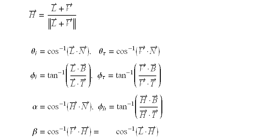
- BRDF computation at a given surface point requiers the definition of a few geometric entities. (refer to FIG. 1)
- ⁇ right arrow over (V) ⁇ is the outgoing direction, ⁇ r ⁇ ( ⁇ circumflex over ( ⁇ right arrow over (V) ⁇ ) ⁇ , ⁇ right arrow over (N) ⁇ ),
- ⁇ right arrow over (L) ⁇ is the incoming direction, ⁇ i ⁇ ( ⁇ circumflex over ( ⁇ right arrow over (L) ⁇ ) ⁇ , ⁇ right arrow over (N) ⁇ ),
- ⁇ right arrow over (N) ⁇ is the surface normal, ⁇ r ⁇ ( ⁇ circumflex over ( ⁇ overscore (V) ⁇ ) ⁇ , ⁇ right arrow over (T) ⁇ ),
- ⁇ right arrow over (T) ⁇ is the surface tangent, ⁇ i ⁇ ( ⁇ circumflex over ( ⁇ overscore (L) ⁇ ) ⁇ , ⁇ right arrow over (T) ⁇ )
- ⁇ right arrow over (H) ⁇ is the bisector vector, ⁇ h ⁇ ( ⁇ circumflex over ( ⁇ overscore (H) ⁇ ) ⁇ , ⁇ right arrow over (T) ⁇ ),
- ⁇ overscore (H) ⁇ is the projection of ⁇ right arrow over (H) ⁇ , ⁇ ( ⁇ circumflex over ( ⁇ right arrow over (V) ⁇ ) ⁇ , ⁇ right arrow over (H) ⁇ ),
- ⁇ right arrow over (B) ⁇ is the bi-normal vector, ⁇ ( ⁇ circumflex over ( ⁇ right arrow over (H) ⁇ ) ⁇ , ⁇ right arrow over (N) ⁇ )
- An ambient component is added sometimes but it can be expressed as a fraction of the Diffuse component.
- the BRDF is a 4D (four dimensional) function for each wavelength, so it is a 5D function into a 3D space in the case of R, G, B model.
- a BRDF texture is computed for the upper hemisphere (distribution of directions of normal). This process concist in discretizing the normal directions of the upper hemisphere.
- ⁇ right arrow over (T) ⁇ is orthogonal to ⁇ right arrow over (N) ⁇ . It can be obtained by the cross product of ⁇ right arrow over (N) ⁇ and ⁇ right arrow over (N) ⁇ xz .
- N ⁇ ⁇ N ⁇ xz T ⁇ ⁇ ( - XY X 2 + Z 2 X 2 + Z 2 - ZY X 2 + Z 2 ) . ( 5 )
- ( ⁇ right arrow over (T) ⁇ , ⁇ right arrow over (B) ⁇ , ⁇ right arrow over (N) ⁇ ) is a 3D space orthonormal basis. Then ⁇ right arrow over (B) ⁇ is computed by cross product of ⁇ right arrow over (N) ⁇ and ⁇ right arrow over (T) ⁇ .
- the size of the texture image is the sampling resolution of the distribution of normal directions. The bigger the texture size, the more accurate is the sampling.
- I and J are the pixel coordinates (raw J and column I). To insure that (X, Y) ⁇ 1, 1 ⁇ 1, 1 ⁇ X and Y are computed as follow:
- the new texture coordinates are function of the vertex normal (normalized).
- U X + 1 2
- V Y + 1 2
- the BRDF texture has to be recomputed.
- the texture coordinates for BRDF remain unchanged as long as the object's normals are unchanged.
- I r ⁇ ⁇ a I a ⁇ +I i ⁇ ( ⁇ right arrow over (N) ⁇ right arrow over (L) ⁇ ) d ⁇ ( k d ⁇ d +k s ⁇ s ⁇ ) (10)
- I r ⁇ k a ⁇ a O d ⁇ +I i ⁇ ( ⁇ right arrow over (N) ⁇ right arrow over (L) ⁇ ) d ⁇ ( k d ⁇ d O d ⁇ +k s ⁇ s ⁇ O s ⁇ )
- the second pass blends the specular BRDF texture with the result of the first pass by adding a specular component to the shading.
- the object is drawn with just the surface texture image without illumination.
- the illumination is computed and kept in the BRDF texture.
- the second pass blends the diffuse dominant BRDF texture with the first pass' result by multiplying texture.
- the third pass blends the specular dominant BRDF texture with the second pass' result by addition.
- the surface is considered of type Double. (refer to FIGS. 9A, 9B)
- a technique for using texture map to discretize and store BRDF values is presented.
- the BRDF texture generated can be applyed onto arbitrary geometry as long as the vertices normals are available.
- the size of the BRDF texture texture defines the computation time spent to evaluate the BRDF.
- Our approach is well suited for mixing BRDF information and surface texture image using texturing features available in hardware.
Abstract
Description
- This patent application claims the priority of U.S. Provisional Application No. 60/244,040 filed on Oct. 26, 2000, entitled “Microfacet Based Texture Map Using Bidirectional Reflectance Distribution Function”, by the same inventor.
- This invention relates to the field of computer graphics and, in particular, to an improved method for CG surface shading using a stored texture map for faster processing.
- Computer graphics (CG) systems create display images frame-by-frame from digital data representing mathematically-described objects in a scene. CG systems have been noteworthy recently in creating computer-generated special effects, animated films, interactive 3D video games, and other interactive or 3D effects in digital media. They are widely used for entertainment and advertising, computer aided design, flight simulation and training, and many other applications.
- In advanced CO applications, a CO development platform is used to create an overall CO media program and accompanying database of scenes and objects, such as the MAYA™ development platform offered by Alias Wavefront, Inc., of Toronto, Ontario, Canada, which is a subsidiary of Silicon Graphics, Inc. The MAYA™ development platform is a 3D modeling, animation, and rendering software package that has advanced interface, workflow, flexibility, and depth features. MAYA includes many tools used for modeling and animation, including setting keyframes and constraints, inverse kinematics, attaching surfaces to skeletons, character modeling, nurbs modeling, character expressions, particle and dynamics suites for rigid and soft bodies, texturing, and tools for rendering including node-based shaders, anti-aliasing, motion blur, and selective raytracing/raycasting. At the heart of MAYA is MEL, its scripting language. Every action, every part of the interface, and every tool is invoked and described by MEL. It is, therefore, possible to create new tools, combinations of tools, completely modify the interface, and tie MAYA in with other software programs using MEL. Further information about the MAYA™ development platform can be obtained from “MAYA Software Rendering: A Technical Overview”, by Andrew Pierce and Kelvin Sung, published by Alias/Wavefront, 1998, 2000.
- The developed CG media program and data files, referred to as “SHOT” data files, can then be rendered into a visual display of the CG media program. The rendering process operates on a “World Task” which includes many different rendering tasks. The many rendering tasks include many independent operations which lend themselves to efficiencies obtained by parallel processing using multiple CPUs. One renderer capable of doing this is the RENDERMAN™ renderer developed by Pixar Animation Studios of Emeryville, Calif.
- However, even with advanced CG systems, the computational intensity of rendering and the large data size of visually rich CG scenes can impose a high computational burden that requires that compromises be made in terms of image quality. For example, the light/color shading o f surfaces of objects in an image scene typically requires computing the surface texture for each point on an object's surface from stored surface characteristic data, then computing the light reflectance characteristic of each such point according to a selected light reflectance model, then computing the reflected light values (typically, its specular and diffuse components) from each such point by applying a light vector from each illumination source (emitted, ambient, diffuse, and specular light) in the scene. Among the different light reflectance models that may be used, the ones based upon the physics of light interaction with surface material characteristics, for example, the bidirectional reflectance distribution function (BDRF), are the most accurate in terms of rendering quality, but among the most expensive (intensive) to compute. As a result, surface shading using a physical light reflectance model such as BRDF has been precluded from use in real-time rendering engines.
- Accordingly, it is a principal object of the present invention to provide an improved method for CG surface shading that would allow the use of a physical light reflectance model in real-time CG rendering. It is a particular object of the invention to utilize the bidirectional reflectance distribution function as a physical light reflectance model in real-time CG rendering.
- In accordance with the present invention, an improved method for computer graphics (CG) surface shading comprises:
- (a) determining surface characteristics and geometry parameters of a surface of an object in a scene during development of a CG program;
- (b) determining for a frame of the scene an incoming light direction illuminating the surface of the object and an outgoing direction of viewing the object in the scene;
- (c) applying a selected bidirectional reflectance distribution function (BRDF) model to compute light reflectance values for a sampled range of normal direction vectors of light reflectance from the surface of the object in the frame of the scene based upon the incoming and outgoing light directions and the surface characteristics and geometry parameters of the surface of the object;
- (d) storing the sampled BRDF values as a texture map of light reflectance for surface shading of the object in the frame of the scene; and
- (e) performing surface shading of the object during real-time rendering by applying the sampled BRDF values in correspondence to normal direction vectors for points on the surface of the object in the frame of the scene.
- The invention technique employs a selected BRDF model during development of a CG program to compute light reflectance values for a sampled range of normal direction vectors as a texture map to be used later during rendering. The BRDF model is applied with a standard model for distribution of normal direction vectors for a given type of surface, and the BRDF values are computed and stored as a look-up table indexed to the sampled range of normal direction vectors. During real-time rendering, surface shading can be readily processed by using the normal direction vector for any given point to look up the stored BRDF value. Shading with BRDF light reflectance values can be combined in one or more passes with shading of other surface texture characteristics, e.g., a facial skin surface textured with hair and facial features. In this manner, the rich tones of a physical light reflectance model can be obtained even for highly textured surfaces during real-time rendering. Besides standard types of light reflectance models (Torrance-Sparrow, Phong, Strauss, etc.), modified types of BRDF models (e.g., Schlick) may also be used to derive a BRDF texture map.
- Other objects, features, and advantages of the present invention will be described in further detail below, with reference to the following drawings:
- FIG. 1 is an illustration of BRDF parameter definition at a given surface point.
- FIG. 2 illustrates distribution of normal direction vectors in a texture map.
- FIG. 3 illustrates BRDF texture map of an object of a given image size.
- FIGS. 4A-4D illustrate a conventional BRDF texture for four different angles of viewing.
- FIGS. 5A and 5B illustrate applying a conventional BRDF texture map on a face model.
- FIGS. 6A and 6B illustrate applying a conventional BRDF texture map on a textured face model.
- FIGS. 7A-7D illustrate a different (Schlick) BRDF texture map on an object for four different angles of viewing.
- FIGS. 8A and 8B illustrate applying a different (Schlick) BRDF texture map on a face model.
- FIGS. 9A and 9B illustrate applying a different (Schlick) BRDF texture map on a textured face model.
- FIG. 10 is a logic diagram of applying BRDF texture map on a textured object.
- A preferred implementation of the improved method of surface shading in accordance with the present invention is described in detail below using the example of a physical light reflectance model for interaction of light with a textured surface. However, it is to be understood that the general principles of the invention have broad applicability to rendering involving other types of surface texture characteristics and physical light reflectance models as well.
- Surface shading of objects in an image scene is conventionally accomplished during rendering by computing the surface texture characteristics for each point on an object's surface from stored surface characteristic and geometry parameters and then computing the light reflectance value from that point. The reflected light for each point is computed based upon the various incoming sources of illumination (emitted, ambient, diffuse, and specular light) on the object. For further information about light illumination and reflection in conventional surface shading, reference is made to “Lighting”, Chapter 6, from “Open GL programming Guide”, Silicon Graphics, Inc., published by Addison-Wesley Publishing Company.
- In conventional CG techniques, the surface of an object can be envisioned as a set of microfacet mirrors that are wrapped over the contour of an object (spherical, ovoid, flat, etc.). The microfacets can have varying orientations (represented by their normal direction vectors) at the minute local level and can result in complex light reflection paths reflecting from a number of microfacets in a complex scattering of light in the vicinity of an observed point. This complex light scattering provides a surface with its characteristic light reflectance “texture”. Modeling the light reflectance texture of a surface can provide a viewer with a more richly rendered image of the surface, as contrasted, for example, to a simple model of a shiny surface with a spot reflection. However, computation of the complex light scattering from microfacets for each point on the surface of the object would be an enormously time-consuming, if not impossible, task for real-time rendering.
- Computing light reflectance can be simplified somewhat using the notion of Bidirectional Reflectance Distribution Function (BRDF) and BRDF lighting techniques. In the BRDF concept, the complex light interactions from microfacets at the minute local level are ignored, and instead the light reflectance for a point on a surface are modeled on the basis of incoming light direction to a point, outgoing light direction (eye view direction) from the point, and the wavelength of light. BRDF can thus be written as a function of light direction vectors and parameters in terms of spherical coordinate geometery rather than cartesian coordinates. The light reflectance values returned for the BRDF function can be derived by evaluating mathematical functions approximating analytical light reflectance models or by sampling empirical measurements of real-world surfaces.
- Conventional analytical models have been developed that generate a wide range of visually interesting light reflectance effects, including the Cook-Torrance, Torrance-Sparrow, Phong, Ward, Strauss, and other models. In general, different models are useful in modeling the light reflectance characteristics of different types of materials. For example, the Ward model is good at modeling the reflectance properties of anisotropic surfaces, such as brushed metal. The Cook-Torrance model is effective at simulating many types of reflective metal, such as copper and gold, and plastics with varying degrees of roughness. In contrast to analytical models, BRDF values can also be acquired through physical measurements with measuring devices like a gonioreflectometer. Acquired BRDF values for many different types of surfaces are available from libraries of several academic institutions and commercial companies. For further details, reference is made to the article entitled “Introduction to BRDF-Based Lighting”, by Chris Wynn, published by Nvidia Corporation, 2000.
- While BRDF models have been proposed as a useful way to derive light reflectance values instead of computing complex light scattering from different types of surfaces, they are not widely used in real-time CG rendering because they are still too computationally intensive for conventional computer graphics hardware in widespread use.
- In the present invention, a selected BRDF function is used to generate a light reflectance texture map during development of a CG program and stored for later use during real-time rendering. The texture map is stored as a look-up table of light reflectance values indexed to normal direction vectors over a sampled range of spherical coordinates. During rendering, the object's surface is shaded by retrieving the stored light reflectance value for the corresponding normal direction vector ascribed to the point on the surface. In this manner, the richness of the BRDF modeling of light reflectance from a surface can be incorporated in surface shading, without the computational cost of using the BRDF model during real-time rendering. This approach is well suited to the demands of real-time rendering using conventional hardware and standard multipass rendering techniques. It is particularly advantageous for shading textured surfaces, such as the human face. An example of the application of a BRDF texture map to surface shading in accordance with the invention is described below. A detailed explanation of the mathematics of BRDF texture map is provided in the accompanying Appendix A.
- FIG. 1 illustrates the BRDF model that is used for creating a light reflectance texture map during development of a CG program. The BRDF model can be thought of in terms of an incoming light direction represented by the negative of light vector L, an outgoing light direction represented by the eye view vector V, a normal direction vector N representing the orientation of the surface at the point P, and a surface tangent vector T and surface normal vector B defining the surface around the point P. The vectors are defined in spherical coordinates in terms of their corresponding surface projections and angles relative to the normal direction vector of the point P being sampled.
- In the invention, complex light scattering analysis for each point on the surface of an object is ignored. Instead, a global light reflectance texture map is generated for a distribution of normal direction vectors representing the range of orientations of points on the surface of the object being modeled. This can be envisioned as a distribution of normal direction vectors in the upper hemisphere of a hypothetical spherical model, as illustrated in FIG. 2. The distribution of vectors represents the surface characteristics and geometry of the surface being modeled with the BRDF model. As mentioned previously, the distribution of normal direction vectors for a given type of surface can be obtained on the basis of selected, conventionally available BDRF surface models. For example, a BRDF surface model for a flat, reflective surface made of brushed metal will have a certain characteristic (anisotropic) distribution of normal direction vectors (in terms of magnitude and direction). A BRDF model of a curved, high reflective smooth surface will have a quite different (isotropic) distribution of normal direction vectors.
- A BRDF texture map of the surface of the object is carried out by evaluation of diffuse and specular components. The computation of BRDF values is a 4D (four dimensional) function for each wavelength, so it is a mapping of a 5D function into a 3D space in the case of R, G, B lighting model. A 2D texture map in spherical coordinates is used to represent the 5D BDRF function. The 2D texture map can be thought of as BRDF values for a distribution of normal direction vectors in the upper hemisphere representing a range of surface points, as illustrated in FIG. 2. The distribution of normal direction vectors determined for a given surface characteristic and geometry are sampled in discrete angular increments over the given range sufficient for a desired level of visual resolution. The normal direction vectors are also normalized to a given unit image size, for example, in the interval [−1,1], as illustrated in FIG. 3.
- The BRDF function parameters (magnitudes and angles) are derived in terms of the incoming light vector L, the view vector V, and the normal direction vectors N. The actual computation of BRDF values is then done by using the derived function parameters and a mathematical model for the light reflectance function. Conventional light reflectance functions, such as Torrance-Sparrow, Phong, Strauss, etc., may be used. In these approaches, the diffuse component of the BRDF values can be assumed to be lambertian and unaffected by surface geometry attenuation or microfacet distribution. A modified approach may also be used, referred to as Schlick, which takes into account the surface characteristics for both diffuse and specular components. This approach is found to give better visual results and is faster for computation than the conventional BRDF models. It combines the diffuse and specular components by multiplying one by the other, instead of summing them.
- The computed values for the BRDF light reflectance texture map is stored as a lookup table indexed to the discretized increments of normal directions. A BRDF texture map is computed for each object surface, direction of light source, and direction of viewing in a scene, If the object's surface normals do not change from frame to frame, then the BRDF values remain unchanged. Thus, for a non-deforming object, there is no need to recompute the BRDF texture map for every frame. The BRDF texture maps are stored as part of the scene data for a CG program. During real-time rendering, the BRDF value for any point on the surface of an object in a scene is retrieved based upon the normal direction vector specified for that point in the scene, and used to derive the shading value for the associated light source in the scene. Examples of the shading results for 4 views of a spherical surface based on the Torrance-Sparrow model are illustrated in FIGS. 4A-4D, and 4 views based upon the Schlick model are illustrated in FIGS. 7A-7D.
- The surface of the object may be without other surface texture characteristics, such as a smooth surface, or may be a highly textured surface, such as a face textured with hair and features like eyebrows and lips. In a surface without texture, and using the conventional BRDF model, the specular component can be mapped on the surface in one pass. Examples of the shading results for an untextured face mapped with conventional BRDF are illustrated in FIGS. 5A and 5B. If the object is textured, its surface diffuses color, so both the diffuse and specular components of the BRDF texture map are used. In the conventional BRDF model, the diffuse component is considered lambertian, and can be incorporated in the hardware performance of the illumination process by using a diffusion coefficient. The diffuse component is combined with the texture of the object's surface on a first pass, and the specular component is added to the shading on a second pass. Examples of the shading results for a textured face mapped with conventional BRDF is illustrated in FIGS. 6A and 6B.
- In the modified Schlick BRDF model, two texture map values are used, one with the diffuse component dominant, and the other with the specular component dominant. If the surface is without texture, only one BRDF texture combining diffuse and specular components is used in one pass (Surface Type Single). Examples of the shading results for an untextured face mapped with Schlick BRDF are illustrated in FIGS. 8A and 8B. If the surface is textured, shading proceeds in three passes. In the first pass, the object is drawn with its surface texture but without illumination. In the second pass, the diffuse dominant BRDF texture is blended with the result of the first pass, and in the third pass, the specular dominant BRDF texture is blended (Surface Type Double). Examples of the shading results for a textured face mapped with Schlick BRDF are illustrated in FIGS. 9A and 9B.
- Referring to FIG. 10, a logic diagram illustrates the overall process steps in the preferred implementation of the invention. During development of a CG program, the surface characteristics and geometry of an object in a scene are determined, as indicated at block 101. Based upon the surface characteristics and geometry, a distribution of normal direction vectors N for the object is determined, relative to the light direction L and view direction V in the scene, at
block 102. The particular BRDF light reflectance model to be used is selected depending upon the type of surface, atblock 103. The BRDF function parameters are computed based upon the parameters of the light direction L, view direction V, and normal direction vectors N for the object, atblock 104. Using the computed function parameters and BRDF model, the BRDF values are computed and stored as a texture map for the object surface in the scene, atblock 105, and retained as scene data awaiting the beginning of real-time rendering, as indicated atblock 106, e.g., upon initialization of a CG video game or movie. - During real-time rendering, a “World Task” for a scene is generated, defining each frame of the scene and its objects and illumination sources, and for each frame the shading function is called, as indicated at
block 107. For a typical shading task, the shading function computes the surface light and color reflected from the illumination sources at each point on an object's surface in the scene. First, the surface characteristic and color properties of the object stored with the scene data are retrieved. Then the light reflected at each point from light sources in the scene is computed. As indicated atblock 108, the stored BRDF texture map is applied to compute the light reflectance values for the points on the object's surface. With the conventional BRDF model, shading proceeds in 2 passes, adding a diffuse component and a spectral component, as indicated atblock 109. With the Schlick BRDF model, shading proceeds in 3 passes, first shading the surface texture features, and blending a diffuse-dominant component and then a spectral-dominant component, as indicated at block 110. - In summary, the invention provides an improved surface shading technique for real-time CG rendering in which a physical light reflectance texture map is computed and stored during the CG development phase, then later applied during the real-time rendering phase. This approach allows the rich texturing of a physical light reflectance model, such as conventional BRDF models or a modified Schlick BRDF model, to be used for shading in real-time rendering. The BRDF texture map can be applied to any arbitrary geometry as long as the vertices of the microfacets on the surface of the object are available. This approach is well suited for real-time rendering using conventional hardware and multipass shading techniques, and also allows BRDF texture map to be used in combination with textured surfaces such as skin.
- It is understood that many other modifications and variations may be devised given the above description of the principles of the invention. It is intended that all such modifications and variations be considered as within the spirit and scope of this invention, as defined in the following claims.
- 1 Introduction
- The reflectance model is a key feature in any rendering engine because it provide the illumination of object in the scene and therefore the pixel color in the image. There have been many reflectance models introduced in computer graphics. Some empirical and some physically based. BRDF is a physically-based model that has been used in many rendering engine because it simulates the physical principles involved in light interaction with surface material. Despite its success in rendering packages, BRDF hasn't been used that much in real time rendering applications because of the expensive cost to compute the function each frame. We present a technique that uses physically based reflectance model (BRDF) in a real-time rendering engine.
- In section 3 the BRDF texture generation is explained. Section 4 details the parameters and geometric entities needed for BRDF evaluation. Algorithmic details and texture mapping are presented in sections 5 and 6. Finally section 7 illustrate application of the technique and implementation details.
- 2 Background
- The interaction of light and surface material can be modeled as relating the incoming radiance (E i) to the outgoing irradiance (Ir) at the surface point P. The relation function ρ is the BRDF (Bidirectional Reflection Distribution Function).
- In this paper any term that is function of the wavelength will be subscripted by A.

- where
- I rλ(P, {right arrow over (V)}) is the irradiance leaving point P in direction {right arrow over (V)},
- I iλ(P, −{right arrow over (L)}) is the radiance reaching point P from direction −{right arrow over (L)},
- ρ λ(P, {right arrow over (V)}, {right arrow over (L)}) is the BRDF value at the surface point P,
- ν is the possible direction of incident light,
- dω is the differential solid angle surrounding direction {right arrow over (L)},
- {right arrow over (N)} is the surface normal (unit vector),
- {right arrow over (L)} is the direction towards light (unit vector),
- {right arrow over (V)} is the direction towards viewer (unit vector),
- P is the surface point being sampled
- 2.1 BRDF Parameters Definition
- BRDF computation at a given surface point requiers the definition of a few geometric entities. (refer to FIG. 1)
- {right arrow over (V)} is the outgoing direction, θ r≡({circumflex over ({right arrow over (V)})}, {right arrow over (N)}),
- {right arrow over (L)} is the incoming direction, θ i≡({circumflex over ({right arrow over (L)})}, {right arrow over (N)}),
- {right arrow over (N)} is the surface normal, φ r≡({circumflex over ({overscore (V)})}, {right arrow over (T)}),
- {right arrow over (T)} is the surface tangent, φ i≡({circumflex over ({overscore (L)})}, {right arrow over (T)})
- {right arrow over (H)} is the bisector vector, φ h≡({circumflex over ({overscore (H)})}, {right arrow over (T)}),
- {overscore (H)} is the projection of {right arrow over (H)}, β≡({circumflex over ({right arrow over (V)})}, {right arrow over (H)}),
- {right arrow over (B)} is the bi-normal vector, α≡({circumflex over ({right arrow over (H)})}, {right arrow over (N)})
- Traditionally two kind of surfaces characteristics are distinguished in BRDF terminology: Diffuse and Specular. The BRDF computation is then carried out by evaluation of the Diffuse and Specular components. This distinction is made in most of BRDF research: ρ=ρ d+ρs.
- An ambient component is added sometimes but it can be expressed as a fraction of the Diffuse component.
- 3 BRDF Texture
- The BRDF is a 4D (four dimensional) function for each wavelength, so it is a 5D function into a 3D space in the case of R, G, B model. We want to use a 2D texture map to represent the BRDF (5D function) which is, at each surface point, have the BRDF available for R, G, B from θ i, θr, φi, φr. We need two (2) parameters (U, V) to access the 2D BRDFtexture.
- A BRDF texture is computed for the upper hemisphere (distribution of directions of normal). This process concist in discretizing the normal directions of the upper hemisphere. The directions in the upper hemisphere are defined by: (refer to FIG. 2)

- For a given pair (X, Y)ε{−1, 1}×{−1, 1}, we compute the corresponding direction vector and then the relevant parameters for BRDF evaluation: {right arrow over (N)}, {right arrow over (T)}, {right arrow over (B)}, θ i, θr, φi, φr, φh, {right arrow over (H)}, β, β
- 4 BRDF Parameters Computation
- 4.1 Normal Vector (Direction) Computation
- To define the normal vector {right arrow over (N)}(X, Y, Z), X and Y are sampled in the interval [−1,1] and Z is deduced by the fact that the vector is normalized.

- If X and Y are outside the unit circle, they are snap back to the circle by normalization. i.e:
- l n =X 2 +Y 2
- if (l n>(1−ε)) then l n ={square root}{square root over (ln)}+ε
- X=X/l n
- Y=Y/l n
- Z is then computed from the new X and Y values.
- {right arrow over (N)}=(X, Y, {square root}{square root over (1−X2=Y2)}) (4)
- 4.2 Tangent and Bi-normal Vectors Computation
- To compute the tangent and bi-normal vectors we need an orthogonal vector to {right arrow over (N)}. The choice of that orthogonal vector will dictate the direction of {right arrow over (T)} and {right arrow over (B)} the tangent and bi-normal vectors. Given {right arrow over (N)}(X, Y, Z) the vector {right arrow over (N)} xz′(−Z, 0, X) is orthogonal to {right arrow over (N)}.

- {right arrow over (T)} is orthogonal to {right arrow over (N)}. It can be obtained by the cross product of {right arrow over (N)} and {right arrow over (N)} xz.

- ({right arrow over (T)}, {right arrow over (B)}, {right arrow over (N)}) is a 3D space orthonormal basis. Then {right arrow over (B)} is computed by cross product of {right arrow over (N)} and {right arrow over (T)}.
- {right arrow over (N)}Λ{right arrow over (T)}={right arrow over (B)} (6)
- 4.3 BRDF Angles and Vectors
- For {right arrow over (L)}, {right arrow over (V)} incident light and view vectors we can now compute θ i, θr, φi, φr, {right arrow over (H)} since we have {right arrow over (T)}, {right arrow over (B)}, {right arrow over (N)}. We also compute φh, α, β. The BRDF parameters will be defined in ({right arrow over (T)}, {right arrow over (B)}, {right arrow over (N)}) basis.
- In basis ({right arrow over (T)}, {right arrow over (B)}, {right arrow over (N)})

- We now have all the parameters needed to compute the BRDF texture.
- 5 BRDF Texture Computation and Mapping
- The parameters defined in the previous section allow the computation of a BRDF texture representing a distribution of normal directions (upper hemisphere).
- 5.1 Algorithm
- The size of the texture image is the sampling resolution of the distribution of normal directions. The bigger the texture size, the more accurate is the sampling.
- For a given texture image size of IMSIZE, I and J are the pixel coordinates (raw J and column I). To insure that (X, Y)ε{−1, 1}×{−1, 1} X and Y are computed as follow:
- (refer to FIG. 3)
- For (I, J)ε{0, IMSIZE−1}×{0, IMSIZE−1}

- The outlines for the BRDF computation algorithm are:
- For (X,Y)ε{−1,1}×{−1,1}
- If ((l n =X 2 +Y 2)>(1−ε)) then

- {right arrow over (N)}={X, Y, Z}
- Compute {right arrow over (T)} and {right arrow over (B)} from Equations (5) and (6)
- Compute θ i, θr, φi, φr, α, β, φh from formulas in previous section.
- Compute the BRDF value for this (X, Y) pair
- To perform the texture map onto a geometry, new texture coordinates have to be evaluated for each vertex based on the computation formula for the BRDF texture.
- The new texture coordinates are function of the vertex normal (normalized). We use the X and Y coordinates of the vertex normal N(X, Y, Z).

- For every new position and/or direction of the light source and/or the view camera, the BRDF texture has to be recomputed. the texture coordinates for BRDF remain unchanged as long as the object's normals are unchanged. For a non-deforming object, there is no need to recompute the BRDF texture coordinates every frame.
- 6 Computation of the BRDF Value
- The actual computation of the BRDF texture values (pixel color) can be done using any of the existing methods(Torrance-Sparrow, Phong, Strauss . . . ).
- We implemented some of the above methods. In all those approaches, the diffuse part of the BRDF was assumed lambertian and wasn't affected by neither the surface geometric attenuation nor the microfacet distribution.

- In [7], Schlick present a different new approach to BRDF computation with optimized functions when necessary, which take into acount the surface characteristics for both diffuse and specular components. As expected, the implementation of this new approach with minor extentions to make it usable for texture map, gave better visual results and is faster than the traditional BRDF computation. The new approach evaluates the BRDF computing the Spectral and Directional components. They are combined by multiplying one by the other instead of summation (Diffuse and Specular). Two types of surfaces are introduced: Single (one spectral component and one directional component) and Diffuse (two spectral components and two directional components).
- The following formulas are extracted from [7]:
- BRDF Components

- Surface Types
- Single: ρλ(t, u, v, l, w)=S λ(u)D(t, v, l, w) Double: ρλ(t, u, v, l, w)=S λ(u)D(t, v, l, w)+(1−S λ(u))S λ′(u)D′(t, v, l, w) (9)
- with
- t=cosα, u=Cosβ
- v=cosθ r, l=cosθi
- w=cosφ h
- In our implementation we used the BRDF parameters r, p introduced in [7] and an additional fresnel parameter to specify if we use the Fresnel term

- or not.
- b=4r(1−r)
- a=(r<0.5)?0:1−b
- c=(r<0.5)?((fresnel?1−b: 0): 0
- In addition to the new parameter fresnel, we used the Beckmann distribution function

- 7 Application and Implementation
- We applyed the BRDF texture map technique to a synthetic skin shader in DANCER rendering engine. A skin texture image painted by an artist is provided. The BRDF texture is combined with the skin texture for object surface shading in two or three passes depending on the approach.
- 7.1 Diffuse Plus Specular (Conventional BRDF)
- A shading using BRDF can be sommarize by the equation
- I rλ=ρa I aλ +I iλ({right arrow over (N)}·{right arrow over (L)})dω(k dρd +k sρsλ) (10)
- If a texture image is used as object diffuse color. The shading equation with texture becomes
- I rλ =k aρa O dλ +I iλ({right arrow over (N)}·{right arrow over (L)})dω(k dρd O dλ +k sρsλ O sλ)
- ρa=ρρd (11)
- The diffuse component of the BRDF is considered lambertian. It can be incorporated in the hardware illumination process by providing a diffuse coefficient

- Then the diffusigue illumination

- will be combined with the texture in the first rendering pass. We only need to compute a specular BRDF texture.
- The second pass blends the specular BRDF texture with the result of the first pass by adding a specular component to the shading. (refer to FIGS. 6A, 6B)
- 7.2 Spectral and Directional (Schlick BRDF)
- In order to accurately apply the BRDF texture with the new approach, two texture are necessary. One with diffuse dominant and one with specular dominant. The shading processes in three passes if BRDF texture is combined with texured skin (surface) and in one pass if the surface is of type Single.
- The three passes process as follow:
- In the first pass the object is drawn with just the surface texture image without illumination. The illumination is computed and kept in the BRDF texture.
- The second pass blends the diffuse dominant BRDF texture with the first pass' result by multiplying texture.
- The third pass blends the specular dominant BRDF texture with the second pass' result by addition. The surface is considered of type Double. (refer to FIGS. 9A, 9B)
- When shading a surface without texture only one BRDF texture combining diffuse and specular (and possibly ambient) is used. (refer to FIGS. 8A, 8B)
- 8 Conclusion
- A technique for using texture map to discretize and store BRDF values is presented. The BRDF texture generated can be applyed onto arbitrary geometry as long as the vertices normals are available. The size of the BRDF texture texture defines the computation time spent to evaluate the BRDF. Our approach is well suited for mixing BRDF information and surface texture image using texturing features available in hardware.
- References
- [1] Michael Ashikhmin, Simon Premo{circumflex over (z)}e, and Peter Shirley. A microfacet-based brdf generator. In Kurt Akeley, editor, SIGGRAPH 2000 Conference Proceedings, Annual Conference Series, pages ???-??? ACM SIGGRAPH, Addison Wesley, August 2000. held in New Orleans, La., Jul. 23-27, 2000.
- [2] Marschner S. Westin S. Lafortune E. Torrance K. and Greenberg D. Reflectance measurements of human skin. In Technical repport, pages ???-??? ???, 1999.
- [3] He X. Torrance K. Sillon P. and Greenberg D. A comprehensive physical model for light reflection. In SIGGRAPH 1991 Conference Proceedings, Annual Conference Series, pages ???-??? ACM SIGGRAPH, Addison Wesley, 1991.
- [4] Watt A. Watt M. Advanced Animation and Rendering Techniques: Theorie and Practice. Addison Wesley, 1992.
- [5] Szymon Rusinkiewicz. A new change of variable for efficient brdf representation. In Technical repport, pages ???-??? Stanford University, 1997.
- [6] Szymon Rusinkiewicz. A survey of brdf representation for computer graphics. In Technical repport, pages ???-??? Stanford University, 1997.
- [7] Christophe Schlick. An inexpensive brdf model for physically-based rendering. In Technical repport, pages ???-??? LaBRI, 1998.
- [8] Foley J. van Dam A. Feiner S. and Hughes J. Computer Graphics: Principles and Practice. Addison Wesley, 1996.
Claims (8)
Priority Applications (4)
| Application Number | Priority Date | Filing Date | Title |
|---|---|---|---|
| US09/899,802 US6765573B2 (en) | 2000-10-26 | 2001-07-06 | Surface shading using stored texture map based on bidirectional reflectance distribution function |
| EP01125264A EP1202222A3 (en) | 2000-10-26 | 2001-10-24 | Method for surface shading using stored texture map |
| JP2001329763A JP2002236938A (en) | 2000-10-26 | 2001-10-26 | Surface shading method using texture map stored on the basis of bidirectional reflection distribution function |
| JP2001329764A JP2002208031A (en) | 2000-10-26 | 2001-10-26 | Surface shading method, program for realizing the same method, computer readable recording medium with the same method recorded, and picture processor |
Applications Claiming Priority (2)
| Application Number | Priority Date | Filing Date | Title |
|---|---|---|---|
| US24404000P | 2000-10-26 | 2000-10-26 | |
| US09/899,802 US6765573B2 (en) | 2000-10-26 | 2001-07-06 | Surface shading using stored texture map based on bidirectional reflectance distribution function |
Publications (2)
| Publication Number | Publication Date |
|---|---|
| US20020080136A1 true US20020080136A1 (en) | 2002-06-27 |
| US6765573B2 US6765573B2 (en) | 2004-07-20 |
Family
ID=26936283
Family Applications (1)
| Application Number | Title | Priority Date | Filing Date |
|---|---|---|---|
| US09/899,802 Expired - Lifetime US6765573B2 (en) | 2000-10-26 | 2001-07-06 | Surface shading using stored texture map based on bidirectional reflectance distribution function |
Country Status (3)
| Country | Link |
|---|---|
| US (1) | US6765573B2 (en) |
| EP (1) | EP1202222A3 (en) |
| JP (2) | JP2002208031A (en) |
Cited By (38)
| Publication number | Priority date | Publication date | Assignee | Title |
|---|---|---|---|---|
| US20020154142A1 (en) * | 2001-04-20 | 2002-10-24 | Koninklijke Philips Electronics N.V. | Display apparatus and image encoded for display by such an apparatus |
| US20030025706A1 (en) * | 2001-08-03 | 2003-02-06 | Ritter Bradford A. | System and method for rendering a texture map utilizing an illumination modulation value |
| US20030234786A1 (en) * | 2002-06-21 | 2003-12-25 | Cole Forrester Hardenbergh | Method and system for automatically generating factored approximations for arbitrary bidirectional reflectance distribution functions |
| US20040070565A1 (en) * | 2001-12-05 | 2004-04-15 | Nayar Shree K | Method and apparatus for displaying images |
| US20040141175A1 (en) * | 2002-07-12 | 2004-07-22 | Leo Baldwin | Method and apparatus for uniform lighting source |
| US20050001836A1 (en) * | 2001-08-21 | 2005-01-06 | Day Michael R. | Method for computing the intensity of specularly reflected light |
| US20050134599A1 (en) * | 2003-07-02 | 2005-06-23 | Shree Nayar | Methods and systems for compensating an image projected onto a surface having spatially varying photometric properties |
| EP1573653A2 (en) * | 2002-11-15 | 2005-09-14 | ESC Entertainment, a California Corporation | Method for digitally rendering skin or like materials |
| US20060038817A1 (en) * | 2004-08-20 | 2006-02-23 | Diehl Avionik Systeme Gmbh | Method and apparatus for representing a three-dimensional topography |
| US20060132486A1 (en) * | 2004-12-20 | 2006-06-22 | Electronics And Telecommunications Research Institute | Rendering apparatus and method for real-time global illumination in real light environment |
| US20070273072A1 (en) * | 2006-05-25 | 2007-11-29 | Simard Suspensions Inc. | Tandem suspension for steerable axles |
| US20070291993A1 (en) * | 2005-04-25 | 2007-12-20 | Nisper Jon K | Measuring an appearance property of a surface using a bidirectional reflectance distribution function |
| US20080068377A1 (en) * | 2006-08-31 | 2008-03-20 | Corel Corporation | Re-coloring a color image |
| US20080309754A1 (en) * | 2004-10-25 | 2008-12-18 | Columbia University | Systems and Methods for Displaying Three-Dimensional Images |
| CN100554944C (en) * | 2005-04-30 | 2009-10-28 | 中国科学院安徽光学精密机械研究所 | Laboratory smoke (water) mist BRDF measuring method |
| US7786993B2 (en) | 2001-10-10 | 2010-08-31 | Sony Computer Entertainment America Llc | Environment mapping |
| US20100277477A1 (en) * | 2009-05-01 | 2010-11-04 | Microsoft Corporation | Modeling Anisotropic Surface Reflectance with Microfacet Synthesis |
| CN101882323A (en) * | 2010-05-19 | 2010-11-10 | 北京航空航天大学 | Microstructure surface global illumination real-time rendering method based on height map |
| US20110148871A1 (en) * | 2009-12-21 | 2011-06-23 | Electronics And Telecommunications Research Institute | Apparatus and method for rendering woven fabric material based on type of weave |
| US8133115B2 (en) | 2003-10-22 | 2012-03-13 | Sony Computer Entertainment America Llc | System and method for recording and displaying a graphical path in a video game |
| US8204272B2 (en) | 2006-05-04 | 2012-06-19 | Sony Computer Entertainment Inc. | Lighting control of a user environment via a display device |
| US8243089B2 (en) | 2006-05-04 | 2012-08-14 | Sony Computer Entertainment Inc. | Implementing lighting control of a user environment |
| US8284310B2 (en) | 2005-06-22 | 2012-10-09 | Sony Computer Entertainment America Llc | Delay matching in audio/video systems |
| US8289325B2 (en) | 2004-10-06 | 2012-10-16 | Sony Computer Entertainment America Llc | Multi-pass shading |
| US20130021359A1 (en) * | 2011-02-18 | 2013-01-24 | Daniel Baker | Method and system for filtering of visual objects |
| US20140028801A1 (en) * | 2012-07-30 | 2014-01-30 | Canon Kabushiki Kaisha | Multispectral Binary Coded Projection |
| US20140267340A1 (en) * | 2013-03-15 | 2014-09-18 | Nvidia Corporation | Material representation data structure and method of representing a material for digital image synthesis |
| US9153065B2 (en) | 2013-02-05 | 2015-10-06 | Google Technology Holdings LLC | System and method for adjusting image pixel color to create a parallax depth effect |
| US20160049001A1 (en) * | 2013-06-25 | 2016-02-18 | Google Inc. | Curvature-Driven Normal Interpolation for Shading Applications |
| CN105474271A (en) * | 2014-02-13 | 2016-04-06 | 吉欧技术研究所股份有限公司 | Three-dimensional map display system |
| US9342817B2 (en) | 2011-07-07 | 2016-05-17 | Sony Interactive Entertainment LLC | Auto-creating groups for sharing photos |
| US20160239998A1 (en) * | 2015-02-16 | 2016-08-18 | Thomson Licensing | Device and method for estimating a glossy part of radiation |
| US20180268614A1 (en) * | 2017-03-16 | 2018-09-20 | General Electric Company | Systems and methods for aligning pmi object on a model |
| US10636201B2 (en) * | 2017-05-05 | 2020-04-28 | Disney Enterprises, Inc. | Real-time rendering with compressed animated light fields |
| CN111586444A (en) * | 2020-06-05 | 2020-08-25 | 广州繁星互娱信息科技有限公司 | Video processing method and device, electronic equipment and storage medium |
| US10786736B2 (en) | 2010-05-11 | 2020-09-29 | Sony Interactive Entertainment LLC | Placement of user information in a game space |
| US11501486B2 (en) * | 2019-08-01 | 2022-11-15 | Sony Interactive Entertainment Inc. | Surface characterisation apparatus and system |
| CN116940827A (en) * | 2022-02-23 | 2023-10-24 | 卡尔蔡司光学国际有限公司 | Computer-implemented method, computer program, data processing system and device for determining a reflection behaviour of a surface of an object, and storage medium having stored thereon instructions for determining a reflection behaviour of a surface of an object |
Families Citing this family (30)
| Publication number | Priority date | Publication date | Assignee | Title |
|---|---|---|---|---|
| US7116333B1 (en) * | 2000-05-12 | 2006-10-03 | Microsoft Corporation | Data retrieval method and system |
| US7106325B2 (en) * | 2001-08-03 | 2006-09-12 | Hewlett-Packard Development Company, L.P. | System and method for rendering digital images having surface reflectance properties |
| JP3962588B2 (en) * | 2002-01-07 | 2007-08-22 | キヤノン株式会社 | 3D image processing method, 3D image processing apparatus, 3D image processing system, and 3D image processing program |
| US7262770B2 (en) * | 2002-03-21 | 2007-08-28 | Microsoft Corporation | Graphics image rendering with radiance self-transfer for low-frequency lighting environments |
| JP2004152015A (en) * | 2002-10-30 | 2004-05-27 | Digital Fashion Ltd | Image processor, image processing program, recording medium with the program recorded thereon, image processing method, shading information acquisition device, and data structure |
| JP4456070B2 (en) * | 2003-03-06 | 2010-04-28 | 株式会社ディジタルメディアプロフェッショナル | Light reflection intensity calculation circuit |
| WO2005124691A1 (en) * | 2004-06-16 | 2005-12-29 | Techno Dream 21 Co., Ltd. | Method of real-time rendering performed by sampling reflection characteristics on an object surface and method for converting the texture size |
| JP4282587B2 (en) * | 2004-11-16 | 2009-06-24 | 株式会社東芝 | Texture mapping device |
| JP4692956B2 (en) * | 2004-11-22 | 2011-06-01 | 株式会社ソニー・コンピュータエンタテインメント | Drawing processing apparatus and drawing processing method |
| JP2007026049A (en) * | 2005-07-15 | 2007-02-01 | Ritsumeikan | Image processing apparatus using reference anisotropic reflection distribution, image processing program, recording medium where same program is recorded, and image processing method |
| JP4693555B2 (en) * | 2005-09-02 | 2011-06-01 | 大日本印刷株式会社 | Two-dimensional image generation method and generation apparatus based on a three-dimensional virtual object with a fiber sheet attached to the surface |
| JP2007257079A (en) * | 2006-03-20 | 2007-10-04 | Digital Fashion Ltd | Texture generation program, texture generation device, and texture generation method |
| US20090046099A1 (en) * | 2006-11-13 | 2009-02-19 | Bunkspeed | Real-time display system |
| US20080117215A1 (en) * | 2006-11-20 | 2008-05-22 | Lucasfilm Entertainment Company Ltd | Providing A Model With Surface Features |
| US9767599B2 (en) * | 2006-12-29 | 2017-09-19 | X-Rite Inc. | Surface appearance simulation |
| JP5059503B2 (en) * | 2007-07-13 | 2012-10-24 | 花王株式会社 | Image composition apparatus, image composition method, and image composition program |
| US7929142B2 (en) * | 2007-09-25 | 2011-04-19 | Microsoft Corporation | Photodiode-based bi-directional reflectance distribution function (BRDF) measurement |
| US20090167762A1 (en) * | 2007-12-26 | 2009-07-02 | Ofer Alon | System and Method for Creating Shaders Via Reference Image Sampling |
| US7796727B1 (en) | 2008-03-26 | 2010-09-14 | Tsi, Incorporated | Aerosol charge conditioner |
| KR101582607B1 (en) * | 2009-04-30 | 2016-01-19 | 삼성전자주식회사 | Semiconductor memory device |
| KR20110053166A (en) | 2009-11-13 | 2011-05-19 | 삼성전자주식회사 | Method and apparatus for lendering 3d object |
| US8248613B2 (en) | 2010-04-29 | 2012-08-21 | Microsoft Corporation | Capturing reflected light from a sampling surface |
| CN102314704B (en) * | 2011-09-21 | 2013-03-20 | 北京航空航天大学 | BRDF (bidirectional reflectance distribution function) -based real-time subsurface scattering rendering method |
| US9275477B2 (en) * | 2011-12-05 | 2016-03-01 | Kabushiki Kaisha Square Enix | Real-time global illumination rendering system |
| KR101526487B1 (en) * | 2013-07-24 | 2015-06-10 | 디게이트 주식회사 | Apparatus for rendering 3D object |
| CN104574492A (en) * | 2014-12-23 | 2015-04-29 | 福建天晴数码有限公司 | Real-time rendering method and device for object composed of multiple layers of materials |
| CN104700445B (en) * | 2015-03-23 | 2018-07-27 | 山东大学 | A kind of BRDF reflection model deriving methods based on measurement data |
| JP6604744B2 (en) * | 2015-05-03 | 2019-11-13 | キヤノン株式会社 | Image processing apparatus, image processing method, image forming system, and program |
| US10504273B2 (en) | 2016-12-09 | 2019-12-10 | Nvidia Corporation | Automatic level-of-detail for physically-based materials |
| US10926176B1 (en) | 2017-03-28 | 2021-02-23 | Kabam, Inc. | Physics engine using depth information |
Family Cites Families (5)
| Publication number | Priority date | Publication date | Assignee | Title |
|---|---|---|---|---|
| US4991971A (en) * | 1989-02-13 | 1991-02-12 | United Technologies Corporation | Fiber optic scatterometer for measuring optical surface roughness |
| JPH11175752A (en) * | 1997-12-15 | 1999-07-02 | Sega Enterp Ltd | Processor and method for image processing |
| JPH11195138A (en) * | 1998-01-06 | 1999-07-21 | Sharp Corp | Picture processor |
| US6552726B2 (en) * | 1998-07-17 | 2003-04-22 | Intel Corporation | System and method for fast phong shading |
| CA2420390A1 (en) * | 2000-08-24 | 2002-02-28 | Immersive Technologies, Llc. | Computerized image system |
-
2001
- 2001-07-06 US US09/899,802 patent/US6765573B2/en not_active Expired - Lifetime
- 2001-10-24 EP EP01125264A patent/EP1202222A3/en not_active Withdrawn
- 2001-10-26 JP JP2001329764A patent/JP2002208031A/en active Pending
- 2001-10-26 JP JP2001329763A patent/JP2002236938A/en active Pending
Cited By (57)
| Publication number | Priority date | Publication date | Assignee | Title |
|---|---|---|---|---|
| US7015924B2 (en) * | 2001-04-20 | 2006-03-21 | Koninklijke Philips Electronics N.V. | Display apparatus and image encoded for display by such an apparatus |
| US20020154142A1 (en) * | 2001-04-20 | 2002-10-24 | Koninklijke Philips Electronics N.V. | Display apparatus and image encoded for display by such an apparatus |
| US20030025706A1 (en) * | 2001-08-03 | 2003-02-06 | Ritter Bradford A. | System and method for rendering a texture map utilizing an illumination modulation value |
| US6753875B2 (en) * | 2001-08-03 | 2004-06-22 | Hewlett-Packard Development Company, L.P. | System and method for rendering a texture map utilizing an illumination modulation value |
| US20050001836A1 (en) * | 2001-08-21 | 2005-01-06 | Day Michael R. | Method for computing the intensity of specularly reflected light |
| US7079138B2 (en) * | 2001-08-21 | 2006-07-18 | Sony Computer Entertainment America Inc. | Method for computing the intensity of specularly reflected light |
| US7786993B2 (en) | 2001-10-10 | 2010-08-31 | Sony Computer Entertainment America Llc | Environment mapping |
| US20040070565A1 (en) * | 2001-12-05 | 2004-04-15 | Nayar Shree K | Method and apparatus for displaying images |
| US20030234786A1 (en) * | 2002-06-21 | 2003-12-25 | Cole Forrester Hardenbergh | Method and system for automatically generating factored approximations for arbitrary bidirectional reflectance distribution functions |
| US7075534B2 (en) | 2002-06-21 | 2006-07-11 | Forrester Hardenbergh Cole | Method and system for automatically generating factored approximations for arbitrary bidirectional reflectance distribution functions |
| US20040141175A1 (en) * | 2002-07-12 | 2004-07-22 | Leo Baldwin | Method and apparatus for uniform lighting source |
| EP1573653A2 (en) * | 2002-11-15 | 2005-09-14 | ESC Entertainment, a California Corporation | Method for digitally rendering skin or like materials |
| EP1573653A4 (en) * | 2002-11-15 | 2007-03-14 | Warner Bros Entertainment Inc | Method for digitally rendering skin or like materials |
| US20050134599A1 (en) * | 2003-07-02 | 2005-06-23 | Shree Nayar | Methods and systems for compensating an image projected onto a surface having spatially varying photometric properties |
| US7663640B2 (en) | 2003-07-02 | 2010-02-16 | The Trustees Of Columbia University In The City Of New York | Methods and systems for compensating an image projected onto a surface having spatially varying photometric properties |
| US8133115B2 (en) | 2003-10-22 | 2012-03-13 | Sony Computer Entertainment America Llc | System and method for recording and displaying a graphical path in a video game |
| US20060038817A1 (en) * | 2004-08-20 | 2006-02-23 | Diehl Avionik Systeme Gmbh | Method and apparatus for representing a three-dimensional topography |
| US8289325B2 (en) | 2004-10-06 | 2012-10-16 | Sony Computer Entertainment America Llc | Multi-pass shading |
| US20080309754A1 (en) * | 2004-10-25 | 2008-12-18 | Columbia University | Systems and Methods for Displaying Three-Dimensional Images |
| US7703924B2 (en) | 2004-10-25 | 2010-04-27 | The Trustees Of Columbia University In The City Of New York | Systems and methods for displaying three-dimensional images |
| US20060132486A1 (en) * | 2004-12-20 | 2006-06-22 | Electronics And Telecommunications Research Institute | Rendering apparatus and method for real-time global illumination in real light environment |
| US20070291993A1 (en) * | 2005-04-25 | 2007-12-20 | Nisper Jon K | Measuring an appearance property of a surface using a bidirectional reflectance distribution function |
| US7944561B2 (en) * | 2005-04-25 | 2011-05-17 | X-Rite, Inc. | Measuring an appearance property of a surface using a bidirectional reflectance distribution function |
| CN100554944C (en) * | 2005-04-30 | 2009-10-28 | 中国科学院安徽光学精密机械研究所 | Laboratory smoke (water) mist BRDF measuring method |
| US8284310B2 (en) | 2005-06-22 | 2012-10-09 | Sony Computer Entertainment America Llc | Delay matching in audio/video systems |
| US8243089B2 (en) | 2006-05-04 | 2012-08-14 | Sony Computer Entertainment Inc. | Implementing lighting control of a user environment |
| US8204272B2 (en) | 2006-05-04 | 2012-06-19 | Sony Computer Entertainment Inc. | Lighting control of a user environment via a display device |
| US20070273072A1 (en) * | 2006-05-25 | 2007-11-29 | Simard Suspensions Inc. | Tandem suspension for steerable axles |
| US7990381B2 (en) * | 2006-08-31 | 2011-08-02 | Corel Corporation | Re-coloring a color image |
| US20080068377A1 (en) * | 2006-08-31 | 2008-03-20 | Corel Corporation | Re-coloring a color image |
| US20110199378A1 (en) * | 2006-08-31 | 2011-08-18 | Corel Corporation | Re-Coloring a Color Image |
| US8358306B2 (en) * | 2006-08-31 | 2013-01-22 | Corel Corporation | Re-coloring a color image |
| US9098945B2 (en) * | 2009-05-01 | 2015-08-04 | Microsoft Technology Licensing, Llc | Modeling anisotropic surface reflectance with microfacet synthesis |
| US20100277477A1 (en) * | 2009-05-01 | 2010-11-04 | Microsoft Corporation | Modeling Anisotropic Surface Reflectance with Microfacet Synthesis |
| US20110148871A1 (en) * | 2009-12-21 | 2011-06-23 | Electronics And Telecommunications Research Institute | Apparatus and method for rendering woven fabric material based on type of weave |
| US11478706B2 (en) | 2010-05-11 | 2022-10-25 | Sony Interactive Entertainment LLC | Placement of user information in a game space |
| US10786736B2 (en) | 2010-05-11 | 2020-09-29 | Sony Interactive Entertainment LLC | Placement of user information in a game space |
| CN101882323A (en) * | 2010-05-19 | 2010-11-10 | 北京航空航天大学 | Microstructure surface global illumination real-time rendering method based on height map |
| US20130021359A1 (en) * | 2011-02-18 | 2013-01-24 | Daniel Baker | Method and system for filtering of visual objects |
| US9684975B2 (en) * | 2011-02-18 | 2017-06-20 | Take-Two Interactive Software, Inc. | Method and system for filtering of visual objects |
| US9342817B2 (en) | 2011-07-07 | 2016-05-17 | Sony Interactive Entertainment LLC | Auto-creating groups for sharing photos |
| US20140028801A1 (en) * | 2012-07-30 | 2014-01-30 | Canon Kabushiki Kaisha | Multispectral Binary Coded Projection |
| US9153065B2 (en) | 2013-02-05 | 2015-10-06 | Google Technology Holdings LLC | System and method for adjusting image pixel color to create a parallax depth effect |
| US9947132B2 (en) * | 2013-03-15 | 2018-04-17 | Nvidia Corporation | Material representation data structure and method of representing a material for digital image synthesis |
| US20140267340A1 (en) * | 2013-03-15 | 2014-09-18 | Nvidia Corporation | Material representation data structure and method of representing a material for digital image synthesis |
| US20160049001A1 (en) * | 2013-06-25 | 2016-02-18 | Google Inc. | Curvature-Driven Normal Interpolation for Shading Applications |
| US9965893B2 (en) * | 2013-06-25 | 2018-05-08 | Google Llc. | Curvature-driven normal interpolation for shading applications |
| CN105474271A (en) * | 2014-02-13 | 2016-04-06 | 吉欧技术研究所股份有限公司 | Three-dimensional map display system |
| KR20160124072A (en) * | 2014-02-13 | 2016-10-26 | 가부시키가이샤 지오 기쥬츠켄큐쇼 | Three-dimensional map display system |
| KR102255552B1 (en) | 2014-02-13 | 2021-05-24 | 가부시키가이샤 지오 기쥬츠켄큐쇼 | Three-dimensional map display system |
| US20160239998A1 (en) * | 2015-02-16 | 2016-08-18 | Thomson Licensing | Device and method for estimating a glossy part of radiation |
| US10607404B2 (en) * | 2015-02-16 | 2020-03-31 | Thomson Licensing | Device and method for estimating a glossy part of radiation |
| US20180268614A1 (en) * | 2017-03-16 | 2018-09-20 | General Electric Company | Systems and methods for aligning pmi object on a model |
| US10636201B2 (en) * | 2017-05-05 | 2020-04-28 | Disney Enterprises, Inc. | Real-time rendering with compressed animated light fields |
| US11501486B2 (en) * | 2019-08-01 | 2022-11-15 | Sony Interactive Entertainment Inc. | Surface characterisation apparatus and system |
| CN111586444A (en) * | 2020-06-05 | 2020-08-25 | 广州繁星互娱信息科技有限公司 | Video processing method and device, electronic equipment and storage medium |
| CN116940827A (en) * | 2022-02-23 | 2023-10-24 | 卡尔蔡司光学国际有限公司 | Computer-implemented method, computer program, data processing system and device for determining a reflection behaviour of a surface of an object, and storage medium having stored thereon instructions for determining a reflection behaviour of a surface of an object |
Also Published As
| Publication number | Publication date |
|---|---|
| EP1202222A2 (en) | 2002-05-02 |
| EP1202222A3 (en) | 2004-09-15 |
| JP2002236938A (en) | 2002-08-23 |
| JP2002208031A (en) | 2002-07-26 |
| US6765573B2 (en) | 2004-07-20 |
Similar Documents
| Publication | Publication Date | Title |
|---|---|---|
| US6765573B2 (en) | Surface shading using stored texture map based on bidirectional reflectance distribution function | |
| US7212207B2 (en) | Method and apparatus for real-time global illumination incorporating stream processor based hybrid ray tracing | |
| Gooch et al. | Interactive technical illustration | |
| US6559849B1 (en) | Animation of linear items | |
| US7230624B2 (en) | Method and apparatus for modeling and real-time rendering of surface detail | |
| Amanatides | Realism in computer graphics: A survey | |
| US7106325B2 (en) | System and method for rendering digital images having surface reflectance properties | |
| US7102647B2 (en) | Interactive horizon mapping | |
| Bastos et al. | Increased photorealism for interactive architectural walkthroughs | |
| Darsa et al. | Walkthroughs of complex environments using image-based simplification | |
| US20010048444A1 (en) | System and method for fast phong shading | |
| Koster et al. | Real-time rendering of human hair using programmable graphics hardware | |
| US7230620B2 (en) | Rendering deformable and animated surface reflectance fields | |
| US20010045956A1 (en) | Extension of fast phong shading technique for bump mapping | |
| Hall et al. | Algorithms for realistic image synthesis | |
| François et al. | Subsurface texture mapping | |
| Miller et al. | On-the-fly texture computation for real-time surface shading | |
| Malhotra | Issues involved in real-time rendering of virtual environments | |
| Willmott | Fuzzy Rendering for High-Quality Image Generation | |
| Seales et al. | Using the Asp for the Interactive Viewing of Polyhedral Scenes | |
| Liu et al. | Environment Lighting for Point Sampled Geometry | |
| Klein et al. | Realreflect–real-time visualization of complex reflectance behaviour in virtual protoyping | |
| Thalmann et al. | Computer graphics and animation | |
| Cohen et al. | State of the art in image synthesis | |
| Lindsay et al. | Spherical Harmonic Lighting of Wavelength-Dependent Phenomena. |
Legal Events
| Date | Code | Title | Description |
|---|---|---|---|
| FEPP | Fee payment procedure |
Free format text: PAYOR NUMBER ASSIGNED (ORIGINAL EVENT CODE: ASPN); ENTITY STATUS OF PATENT OWNER: LARGE ENTITY |
|
| AS | Assignment |
Owner name: SQUARE ENIX CO., LTD. (FORMERLY SQUARE CO., LTD.), Free format text: CERTIFICATE OF MERGED NAME CHANGE;ASSIGNOR:KOUADIO, CYRIAQUE;REEL/FRAME:015431/0027 Effective date: 20010227 |
|
| STCF | Information on status: patent grant |
Free format text: PATENTED CASE |
|
| FPAY | Fee payment |
Year of fee payment: 4 |
|
| AS | Assignment |
Owner name: KABUSHIKI KAISHA SQUARE ENIX (ALSO AS SQUARE ENIX Free format text: CHANGE OF NAME;ASSIGNOR:KABUSHIKI KAISHA SQUARE ENIX (ALSO TRADING AS SQUARE ENIX CO., LTD.);REEL/FRAME:022368/0822 Effective date: 20081009 |
|
| FPAY | Fee payment |
Year of fee payment: 8 |
|
| FPAY | Fee payment |
Year of fee payment: 12 |