US20020131370A1 - Clock offset estimation with bias correction - Google Patents
Clock offset estimation with bias correction Download PDFInfo
- Publication number
- US20020131370A1 US20020131370A1 US09/740,252 US74025200A US2002131370A1 US 20020131370 A1 US20020131370 A1 US 20020131370A1 US 74025200 A US74025200 A US 74025200A US 2002131370 A1 US2002131370 A1 US 2002131370A1
- Authority
- US
- United States
- Prior art keywords
- node
- clock
- estimate
- nodes
- time
- Prior art date
- Legal status (The legal status is an assumption and is not a legal conclusion. Google has not performed a legal analysis and makes no representation as to the accuracy of the status listed.)
- Granted
Links
Images


Classifications
-
- H—ELECTRICITY
- H04—ELECTRIC COMMUNICATION TECHNIQUE
- H04J—MULTIPLEX COMMUNICATION
- H04J3/00—Time-division multiplex systems
- H04J3/02—Details
- H04J3/06—Synchronising arrangements
- H04J3/0635—Clock or time synchronisation in a network
- H04J3/0638—Clock or time synchronisation among nodes; Internode synchronisation
- H04J3/0658—Clock or time synchronisation among packet nodes
- H04J3/0661—Clock or time synchronisation among packet nodes using timestamps
- H04J3/0667—Bidirectional timestamps, e.g. NTP or PTP for compensation of clock drift and for compensation of propagation delays
-
- G—PHYSICS
- G06—COMPUTING; CALCULATING OR COUNTING
- G06F—ELECTRIC DIGITAL DATA PROCESSING
- G06F1/00—Details not covered by groups G06F3/00 - G06F13/00 and G06F21/00
- G06F1/04—Generating or distributing clock signals or signals derived directly therefrom
- G06F1/14—Time supervision arrangements, e.g. real time clock
Definitions
- the present invention relates to synchronization of clocks. More specifically, the present invention relates to estimation and correction of clock offset in distributed resources interconnected by a network, such as the Internet.
- Clock synchronization involves two aspects: frequency synchronization and time synchronization.
- the former means that element clocks run at the same frequency, and the latter means that elements agree at a particular epoch with respect to the coordinated universal time (UTC), i.e., there is no offset between element clocks.
- UTC coordinated universal time
- NTP Network Time Protocol
- D. Mills Network Time Protocol ( version 3 ) Specification, Implementation and Analysis RFC 1305, March 1992.
- NTP Network Time Protocol
- One of the most important network clock synchronization issues addressed by NTP is how to use the collected data to estimate the clock offset between a pair of network elements.
- present inventive techniques In addition to estimating the clock offset, present inventive techniques also estimate the bias of the estimation and attempt to correct any such bias. As a result, present inventive algorithms show significant improvement in terms of convergence speed and accuracy. Illustrative embodiments of present inventive algorithms will be referred to as Separate Direction Estimation Algorithms with Bias Correction (SDEABC).
- SDEABC Separate Direction Estimation Algorithms with Bias Correction
- messages are exchanged (bi-directionally) between pairs of network elements, such messages including timestamps indicative of sending and receiving times noted at each stop.
- variable components of delay for each message direction need not be characterized by identical probability distribution functions, e.g., when links in each direction are differently loaded, undesired bias of estimates for clock offset can emerge.
- Illustrative embodiments of the present invention avoid errors in estimates of variable delay minimums by separately determining these minimums, e.g., by advantageously employing separate empirical probability distributions for each direction.
- FIG. 1 illustrates time relations in sending messages between network elements.
- FIG. 2 shows an illustrative network embodiment of the present invention having a single server node for interacting with a plurality of other nodes to effect clock correction at such other nodes.
- FIG. 3 shows an illustrative network embodiment of the present invention having a hierarchy of server nodes with lowest order server nodes for interacting with other network nodes to effect clock correction at such other nodes.
- each of a pair of network elements exchanges data packets (timing messages) with the other of the pair.
- One of such a pair is referred to as a sender, and the other as a receiver with respect to a particular packet. Based on time stamps contained in these timing messages, the clock offset between the sender and the receiver is estimated.
- timing messages are sent between network elements as shown in FIG. 1, where activities at a sender 100 and a receiver 110 are shown for a particular round of message exchanges.
- the i-th message includes a time stamp T i 0 indicating current time as known at the sender 100 when the message is sent to the receiver 110 .
- receiver 110 puts a time stamp T i 1 in the received message.
- the receiver then puts another time stamp T i 2 on the message immediately before sending the message back to the sender.
- sender 100 receives the message, it records the receiving time T i 3 .
- ⁇ be the receiver's clock offset from the sender. That is, if at a given instant the receiver's clock shows time t s and the sender's clock shows time t c , then ⁇ +E,dus, ⁇ t s ⁇ t c . It proves convenient to denote the fixed delay from the sender to the receiver (called upward direction) by d u and the fixed delay from the receiver to the sender (called downward direction) by d d . In this representation, the fixed delay includes all non-variable components of the delay such as transmission delay and propagation delay.
- variable delay component is the part of the delay that would not occur under ideal conditions, and includes such delays as packet queuing delay and delay due to the unavailability of shared resources (e.g., CPU or bandwidth).
- the SDEA is asymptotically unbiased if the pdf of both e i u ⁇ 0 and e i d ⁇ 0 is positive near 0.
- R The empirical distribution of a random variable R ⁇ 0 is illustratively constructed in a manner now to be described.
- R is independently sampled n times with the result being r 1 , . . . , r n .
- r 1:n ⁇ r 2:n ⁇ . . . ⁇ r n:n , where each r i:n is from the original sample set.
- FIG. 2 shows an illustrative single-server network deployment of present inventive techniques.
- Nodes 220 -i may be routers, switches, servers of various kinds, network end points (including terminals, workstations or computers), or any other kind of network node.
- Each of nodes 220 -i has a clock and messaging facilities for exchanging messages with time server 200 in the manner described above.
- time server 200 forms one of the pair of nodes and, in turn, one or more (typically all) of the nodes 220 -i forms the other of the node pair for purposes of exchanging time-stamped messages and deriving offset estimates and estimate bias information. While each of the nodes 220 -i may have equal access to time server 200 , priorities may be accorded some nodes 220 -i, or some nodes 220 -i may be accorded access to server 200 more frequently.
- time server 200 will provide clock offset estimates and estimate bias information as described above, which information is available at nodes 220 -i for correcting clock offset.
- N may have a value of 1, so that only a single network node device may interact with a particular time server.
- time server 200 is shown as a separate dedicated function network node, it will be understood that the function of network node 200 may be included in a node performing other functions.
- many network arrangements will have a plurality of time servers, each serving network nodes connected on a respective network or sub-network 210 .
- FIG. 3 shows an illustrative alternative network arrangement in which a plurality of time servers 330 and 340 -i
- Each of the networks 310 -i has one or more network nodes capable of accessing the respective time server connected to the network.
- network 310 - 1 has nodes 350 - 1 l through 350 - 1 P connected to it.
- network 310 -M is shown having nodes 350 -M 1 through 350 -MQ.
- P and Q may be any integer.
- time server 330 exchanges time-stamped messages with each of the time servers 340 -i to provide the latter with offset estimates and estimate bias information of the type illustrated above to permit clock correction at the illustrative (second-level) time servers 340 -i.
- Each of the time servers 340 -i then serves the clock correction requirements of respective nodes 350 -xx in the same manner.
- each level (after the first or highest) derives clock synchronization information from a time server at the next highest level.
- the number of nodes will generally vary from one network 310 -i to another, and all or some of networks 310 -i may be sub-networks of a larger network.
- time servers may be connected to nodes such as 350 -xx and to a next lower order node as well. Some or all time servers may be located in the same local area or distributed over a wide area (including globally) to meet load and geographic distribution requirements for clock synchronization service.
- Access to respective time servers by particular nodes may be scheduled (e.g., periodic), dependent upon availability of time server resources, dependent on prior clock offset behavior at particular nodes (or subsidiary time servers) or detected conditions at such nodes or subsidiary time servers.
- Exchange of messages and derivation of correction information in accordance with present inventive teachings may be initiated, in appropriate cases, by a particular time server or by a node (or subsidiary time server) for which the particular time server provides clock synchronization services. In each case, however, the time server acts as the reference source of time in determining offset using exchanges of time-stamped messages of the types described above.
- a particular node may request that an associated time server initiate a synchronization sequence and supply the results to the particular node.
Abstract
Description
- The present invention relates to synchronization of clocks. More specifically, the present invention relates to estimation and correction of clock offset in distributed resources interconnected by a network, such as the Internet.
- Accurate and reliable time information is necessary for many systems and applications involving distributed resources, including networked systems and processes typified by the Internet. In such systems, different functional elements are required to have their clocks synchronized. Clock synchronization involves two aspects: frequency synchronization and time synchronization. The former means that element clocks run at the same frequency, and the latter means that elements agree at a particular epoch with respect to the coordinated universal time (UTC), i.e., there is no offset between element clocks. For many purposes, it is appropriate to focus on estimating clock offset and to assume higher order effects, such as the frequency offset, can be ignored or provided for separately.
- Clock synchronization issues have been extensively addressed in the literature. See, for example, D. Mills, Internet time synchronization: the Network Time Protocol, IEEE Trans. Communications, Vol. 39, No. 10, October 1991; D. Mitra, Network synchronization: analysis of a hybrid of master-slave and mutual synchronization, IEEE Trans. Communications, COM-28, 8 (August 1980), pp. 1245-1259; and N. W. Rickert, Non Byzantine clock synchronization—a programming experiment, ACM Operating Systems Review 22, 1 (January 1988), pp. 73-78.
- A well-known clock synchronization protocol that has been successfully deployed in the Internet is the Network Time Protocol (NTP), described, for example, in D. Mills, Network Time Protocol (version 3 ) Specification, Implementation and Analysis RFC 1305, March 1992. One of the most important network clock synchronization issues addressed by NTP is how to use the collected data to estimate the clock offset between a pair of network elements.
- In V. Paxson, On Calibrating Measurements of Packet Transit Times, LBNL-41535, ftp://ftp.ee.lbl.gov/papers/vp-clocks-sigmetrics98.ps.gz, March, 1998 (and in a shortened paper with the same title published in Proc. ACM Sigmetrics98, Jun. 22-26, 1998), the author proposed a new algorithm for clock offset estimation. For easy reference, this algorithm will be referred to as the Separate Direction Estimation Algorithm (SDEA). While SDEA can provide improved performance relative to the NTP algorithm, SDEA nevertheless suffers from significant limitations, especially in applying SDEA to contexts in which loading is different for each of the directional links between pairs of network elements.
- Limitations of the prior art are overcome and a technical advance is made in accordance with the present invention, illustrative embodiments of which are presented in the following detailed description. In particular, limitations of the NTP algorithm and SDEA are overcome and SDEA techniques are extended and improved in accordance with present inventive teachings.
- In addition to estimating the clock offset, present inventive techniques also estimate the bias of the estimation and attempt to correct any such bias. As a result, present inventive algorithms show significant improvement in terms of convergence speed and accuracy. Illustrative embodiments of present inventive algorithms will be referred to as Separate Direction Estimation Algorithms with Bias Correction (SDEABC).
- In accordance with one aspect of present inventive methods, messages are exchanged (bi-directionally) between pairs of network elements, such messages including timestamps indicative of sending and receiving times noted at each stop. Because variable components of delay for each message direction need not be characterized by identical probability distribution functions, e.g., when links in each direction are differently loaded, undesired bias of estimates for clock offset can emerge. Illustrative embodiments of the present invention avoid errors in estimates of variable delay minimums by separately determining these minimums, e.g., by advantageously employing separate empirical probability distributions for each direction.
- FIG. 1 illustrates time relations in sending messages between network elements.
- FIG. 2 shows an illustrative network embodiment of the present invention having a single server node for interacting with a plurality of other nodes to effect clock correction at such other nodes.
- FIG. 3 shows an illustrative network embodiment of the present invention having a hierarchy of server nodes with lowest order server nodes for interacting with other network nodes to effect clock correction at such other nodes.
- Separate Direction Estimation Algorithm
- In network clock synchronization, each of a pair of network elements exchanges data packets (timing messages) with the other of the pair. One of such a pair is referred to as a sender, and the other as a receiver with respect to a particular packet. Based on time stamps contained in these timing messages, the clock offset between the sender and the receiver is estimated.
- More specifically, timing messages are sent between network elements as shown in FIG. 1, where activities at a
sender 100 and areceiver 110 are shown for a particular round of message exchanges. At the i-th round of message exchange, the i-th message includes a time stamp Ti 0 indicating current time as known at thesender 100 when the message is sent to thereceiver 110. Immediately upon reception of this message,receiver 110 puts a time stamp Ti 1 in the received message. The receiver then puts another time stamp Ti 2 on the message immediately before sending the message back to the sender. Whensender 100 receives the message, it records the receiving time Ti 3. Using Ti 0,Ti 1,Ti 2,Ti 3, for i=1, 2, . . . , the sender computes an estimate of the clock offset as betweensender 100 andreceiver 110. - Let θ be the receiver's clock offset from the sender. That is, if at a given instant the receiver's clock shows time t s and the sender's clock shows time tc , then θ+E,dus, Δts−tc. It proves convenient to denote the fixed delay from the sender to the receiver ( called upward direction) by duand the fixed delay from the receiver to the sender (called downward direction) by dd. In this representation, the fixed delay includes all non-variable components of the delay such as transmission delay and propagation delay.
- Let e i u denote the variable component of the delay of the i-th message from the sender to the receiver and ei d denote the variable component of delay from the receiver to the sender. The variable delay component is the part of the delay that would not occur under ideal conditions, and includes such delays as packet queuing delay and delay due to the unavailability of shared resources (e.g., CPU or bandwidth).
- We then have the following equations

- For ease of further description of present inventive algorithms, it proves convenient to define X i+E,dus, ΔTi 1−Ti 0 and Yi+E,dus, ΔTi 3−Ti 2, where i=1, . . . , n after the exchange of n messages.
- The above-cited SDEA keeps the smallest values of X i and Yi, viz., it keeps variables

- The estimate for θ using n samples is then computed as
- {circumflex over (θ)}n=(U n −V n)/2. (3)
- Separate Direction Estimation Algorithm with Bias Correction (SDEABC)
- From (3), with E[·] as the expected value operator we can see that, assuming d u=dd,

- Therefore, the SDEA is asymptotically unbiased if the pdf of both e i u≧0 and ei d ≧0 is positive near 0. However, with a finite number of samples, the estimator is biased if

- a not unlikely event because of differences between uplink and downlink traffic loading. As will be seen, illustrative embodiments of the present invention reduce such errors in estimates due to bias.
- The empirical distribution of a random variable R≧0 is illustratively constructed in a manner now to be described. Suppose R is independently sampled n times with the result being r 1, . . . , rn. We rearrange the n samples so that r1:n <r2:n≦. . . ≦rn:n, where each ri:n is from the original sample set. Further, let r0:n=0 and rn+1:n=∞. The empirical distribution of R is then

- where I(·) is an indicator function, i.e., I(·)=1 when the argument of I is satisfied, and is 0 otherwise. Equivalently, the complementary distribution function is

- Note that since the intervals [r i−1.n, ri:n) are non-overlapping,

- Suppose that independent, identically distributed (i.i.d.) random variables R i, i=1, 2, . . . ,n have a distribution function F(x). Then, mini=1 n{Ri} has the complementary distribution functions (1−F(x))n. Define

- By using the empirical distribution function F n(x) to replace F(x), an estimate of

- is obtained as

- As shown in (4), the bias of the SDEA estimator is

- and an estimate of this bias, {circumflex over (b)} n , is given by

- Based on the foregoing, it can readily be seen that a more accurate determination can be made of clock offset by correcting for bias of estimates made using SDEA. That is, by determining analytically what the bias in an estimate using SDEA is in a particular environment, correcting by an amount equal to the bias achieves a more accurate estimate of clock offset. This more accurately estimated correction is then advantageously applied to the out-of-synchronization clock. Moreover, the expected value of the bias provides a monitor for the analytical process; variations of this expected value over time can signal conditions in a network that may indicate greater or lesser confidence in clock offset estimates.
- In accordance with an approach that is preferred for some applications, a method again proceeds from evaluation of {circumflex over (θ)} n=(Un −Vn)/2, as in Eq. (3). Since

- forming the expected value of each side of Eq. (3) and employing the notation from Eq. (8) for each of random variables U n and Vn yields
- We may take

- but in forming an estimate of b n, the bias in the estimate of θ after n samples, we employ

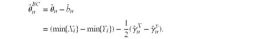
- Then, in accordance with the present approach, a bias-corrected (BC) estimate (SDEABC) for θ is given by
- FIG. 2 shows an illustrative single-server network deployment of present inventive techniques. Specifically, FIG. 2 shows a
time server 200 connected through anetwork 210 to a plurality of other network nodes 220-i, i=1, 2, . . . , N. Nodes 220-i may be routers, switches, servers of various kinds, network end points (including terminals, workstations or computers), or any other kind of network node. Each of nodes 220-i has a clock and messaging facilities for exchanging messages withtime server 200 in the manner described above. That is,time server 200 forms one of the pair of nodes and, in turn, one or more (typically all) of the nodes 220-i forms the other of the node pair for purposes of exchanging time-stamped messages and deriving offset estimates and estimate bias information. While each of the nodes 220-i may have equal access totime server 200, priorities may be accorded some nodes 220-i, or some nodes 220-i may be accorded access toserver 200 more frequently. - By exchanging messages with nodes 220-i,
time server 200 will provide clock offset estimates and estimate bias information as described above, which information is available at nodes 220-i for correcting clock offset. Of course, N may have a value of 1, so that only a single network node device may interact with a particular time server. Whiletime server 200 is shown as a separate dedicated function network node, it will be understood that the function ofnetwork node 200 may be included in a node performing other functions. Likewise, many network arrangements will have a plurality of time servers, each serving network nodes connected on a respective network orsub-network 210. - FIG. 3 shows an illustrative alternative network arrangement in which a plurality of
time servers 330 and 340-i, i=1, 2, . . . , M, are connected in hierarchical relation through a plurality of networks 310-i, i =1, 2, . . . , M. In the illustrative arrangement of FIG. 3, only two levels are shown in the server hierarchy, but those skilled in the art will recognize that any number of levels of time servers may be used. Likewise, while the number of networks is shown equal to the number of nodes at the lowest hierarchical level, no such limitation is required in practicing the present invention using a hierarchical arrangement of time servers. Each of the networks 310-i has one or more network nodes capable of accessing the respective time server connected to the network. By way of illustration, network 310-1 has nodes 350-1l through 350-1P connected to it. Likewise, network 310-M is shown having nodes 350-M1 through 350-MQ. Here, P and Q may be any integer. - In operation,
time server 330 exchanges time-stamped messages with each of the time servers 340-i to provide the latter with offset estimates and estimate bias information of the type illustrated above to permit clock correction at the illustrative (second-level) time servers 340-i. Each of the time servers 340-i then serves the clock correction requirements of respective nodes 350-xx in the same manner. Of course, when more than two hierarchical levels of time servers are used, each level (after the first or highest) derives clock synchronization information from a time server at the next highest level. The number of nodes will generally vary from one network 310-i to another, and all or some of networks 310-i may be sub-networks of a larger network. Some time servers may be connected to nodes such as 350-xx and to a next lower order node as well. Some or all time servers may be located in the same local area or distributed over a wide area (including globally) to meet load and geographic distribution requirements for clock synchronization service. - Access to respective time servers by particular nodes (or subordinate time servers) may be scheduled (e.g., periodic), dependent upon availability of time server resources, dependent on prior clock offset behavior at particular nodes (or subsidiary time servers) or detected conditions at such nodes or subsidiary time servers. Exchange of messages and derivation of correction information in accordance with present inventive teachings may be initiated, in appropriate cases, by a particular time server or by a node (or subsidiary time server) for which the particular time server provides clock synchronization services. In each case, however, the time server acts as the reference source of time in determining offset using exchanges of time-stamped messages of the types described above. Thus, for example, a particular node (routinely, or in response to conditions detected at that node) may request that an associated time server initiate a synchronization sequence and supply the results to the particular node. Numerous and varied particular applications of the present inventive principles, all within the spirit of the present description and scope of the attached claims, will prove useful to those skilled in the art.
Claims (19)


Priority Applications (1)
| Application Number | Priority Date | Filing Date | Title |
|---|---|---|---|
| US09/740,252 US7023884B2 (en) | 2000-12-19 | 2000-12-19 | Clock offset estimation with bias correction |
Applications Claiming Priority (1)
| Application Number | Priority Date | Filing Date | Title |
|---|---|---|---|
| US09/740,252 US7023884B2 (en) | 2000-12-19 | 2000-12-19 | Clock offset estimation with bias correction |
Publications (2)
| Publication Number | Publication Date |
|---|---|
| US20020131370A1 true US20020131370A1 (en) | 2002-09-19 |
| US7023884B2 US7023884B2 (en) | 2006-04-04 |
Family
ID=24975689
Family Applications (1)
| Application Number | Title | Priority Date | Filing Date |
|---|---|---|---|
| US09/740,252 Expired - Lifetime US7023884B2 (en) | 2000-12-19 | 2000-12-19 | Clock offset estimation with bias correction |
Country Status (1)
| Country | Link |
|---|---|
| US (1) | US7023884B2 (en) |
Cited By (29)
| Publication number | Priority date | Publication date | Assignee | Title |
|---|---|---|---|---|
| US20020031085A1 (en) * | 2000-09-13 | 2002-03-14 | Nec Corporation | Communication network system and communication network node for use in the same communication network system |
| US20020131398A1 (en) * | 2001-03-13 | 2002-09-19 | Fantasma | Maintaining a global time reference among a group of networked devices |
| US20030048811A1 (en) * | 2001-09-11 | 2003-03-13 | Robie Edward Adams | Methods, systems and computer program products for synchronizing clocks of nodes on a computer network |
| WO2004038971A1 (en) * | 2002-10-25 | 2004-05-06 | Siemens Plc. | A method of determining a timing offset between a first clock and a second clock in a communications network |
| GB2399263A (en) * | 2003-03-07 | 2004-09-08 | Zarlink Semiconductor Ltd | Clock synchronisation over a packet network |
| US6952456B1 (en) | 2000-06-21 | 2005-10-04 | Pulse-Link, Inc. | Ultra wide band transmitter |
| US7221686B1 (en) * | 2001-11-30 | 2007-05-22 | Meshnetworks, Inc. | System and method for computing the signal propagation time and the clock correction for mobile stations in a wireless network |
| US20080141054A1 (en) * | 2006-12-08 | 2008-06-12 | Radoslav Danilak | System, method, and computer program product for providing data redundancy in a plurality of storage devices |
| US20080147569A1 (en) * | 2006-12-04 | 2008-06-19 | Penson Worldwide, Inc. | Real time trading of foreign financial instruments in local currency |
| US20080183895A1 (en) * | 2007-01-31 | 2008-07-31 | International Business Machines Corporation | Facilitating synchronization of servers in a coordinated timing network |
| US20080183897A1 (en) * | 2007-01-31 | 2008-07-31 | International Business Machines Corporation | Employing configuration information to determine the role of a server in a coordinated timing network |
| US20080183877A1 (en) * | 2007-01-31 | 2008-07-31 | International Business Machines Corporation | Establishing a logical path between servers in a coordinated timing network |
| US20080183899A1 (en) * | 2007-01-31 | 2008-07-31 | International Business Machines Corporation | Server time protocol messages and methods |
| US20080243673A1 (en) * | 2007-03-26 | 2008-10-02 | Ralph Bruce Ferguson | Methods to improve accuracy and precision of timestamps for financial data |
| US20090024512A1 (en) * | 2007-06-18 | 2009-01-22 | Charles Keller Reid | Order routing system and method incorporating dark pools |
| EP2037602A1 (en) * | 2007-09-11 | 2009-03-18 | Lucent Technologies Inc. | System and method for supervising a plurality of oscillators in a network |
| US20090100189A1 (en) * | 2007-10-04 | 2009-04-16 | Frank Bahren | Data network with a time synchronization system |
| US20090192949A1 (en) * | 2005-10-31 | 2009-07-30 | Penson Worldwide, Inc. | Modeling financial instruments using bid and ask prices |
| US20090257456A1 (en) * | 2008-04-10 | 2009-10-15 | International Business Machines Corporation | Coordinated timing network having servers of different capabilities |
| US7689718B2 (en) | 2007-01-31 | 2010-03-30 | International Business Machines Corporation | Channel subsystem server time protocol commands and system therefor |
| US20100100761A1 (en) * | 2008-10-21 | 2010-04-22 | International Business Machines Corporation | Maintaining a primary time server as the current time server in response to failure of time code receivers of the primary time server |
| US7783913B2 (en) | 2007-01-31 | 2010-08-24 | International Business Machines Corporation | Facilitating recovery in a coordinated timing network |
| US20100325031A1 (en) * | 2009-06-18 | 2010-12-23 | Penson Worldwide, Inc. | Method and system for trading financial assets |
| US7899894B2 (en) | 2006-08-30 | 2011-03-01 | International Business Machines Corporation | Coordinated timing network configuration parameter update procedure |
| US7925916B2 (en) | 2008-04-10 | 2011-04-12 | International Business Machines Corporation | Failsafe recovery facility in a coordinated timing network |
| US8031690B2 (en) | 1999-09-10 | 2011-10-04 | Pulse-Link, Inc. | Ultra wide band communication network |
| US9398534B2 (en) | 2011-09-08 | 2016-07-19 | Nordic Semiconductor Asa | Radio communication system with energy efficient devices and method to use same |
| CN106452650A (en) * | 2016-12-01 | 2017-02-22 | 重庆邮电大学 | Clock synchronizing frequency deviation estimation method applicable to multi-hop wireless sensor network |
| CN112543078A (en) * | 2020-11-24 | 2021-03-23 | 北京卓越航导科技有限责任公司 | Network time server calibration method and device based on satellite common view |
Families Citing this family (13)
| Publication number | Priority date | Publication date | Assignee | Title |
|---|---|---|---|---|
| US6970481B2 (en) * | 2001-04-17 | 2005-11-29 | Microsoft Corporation | Methods and systems for distributing multimedia data over heterogeneous networks |
| US7257133B2 (en) * | 2002-09-30 | 2007-08-14 | Lucent Technologies Inc. | Method for estimating offset for clocks at network elements |
| US8001076B2 (en) * | 2005-07-12 | 2011-08-16 | International Business Machines Corporation | Ranging scalable time stamp data synchronization |
| KR100772174B1 (en) | 2006-10-18 | 2007-11-01 | 한국전자통신연구원 | Method for providing network time using timestamp of micro engine in line-card |
| US8036247B2 (en) | 2007-01-05 | 2011-10-11 | Frank Paul R | System and method of synchronizing real time clock values in arbitrary distributed systems |
| US20080175275A1 (en) * | 2007-01-22 | 2008-07-24 | Samsung Electronics Co., Ltd. | Time synchronization method between nodes in network and apparatus for implementing the same |
| US7969891B2 (en) * | 2007-04-24 | 2011-06-28 | Microsoft Corporation | Adjustment of clock approximations |
| GB2454937A (en) * | 2007-11-23 | 2009-05-27 | Ubiquisys Ltd | Acquiring time references for a telecommunications basestation from a time server |
| US8073976B2 (en) * | 2008-03-27 | 2011-12-06 | Microsoft Corporation | Synchronizing clocks in an asynchronous distributed system |
| US8255732B2 (en) * | 2008-05-28 | 2012-08-28 | The United States Of America, As Represented By The Administrator Of The National Aeronautics And Space Administration | Self-stabilizing byzantine-fault-tolerant clock synchronization system and method |
| US8719452B1 (en) | 2011-07-29 | 2014-05-06 | Google Inc. | Correction of client-assigned timestamps |
| US10142088B2 (en) | 2014-01-31 | 2018-11-27 | University Of North Dakota | Network clock skew estimation and calibration |
| US10025344B2 (en) | 2015-04-21 | 2018-07-17 | The United States Of America As Represented By The Administrator Of Nasa | Self-stabilizing distributed symmetric-fault tolerant synchronization protocol |
Citations (6)
| Publication number | Priority date | Publication date | Assignee | Title |
|---|---|---|---|---|
| US4142069A (en) * | 1977-06-20 | 1979-02-27 | The United States Of America As Represented By The Secretary Of The Army | Time reference distribution technique |
| US5907685A (en) * | 1995-08-04 | 1999-05-25 | Microsoft Corporation | System and method for synchronizing clocks in distributed computer nodes |
| US6023769A (en) * | 1998-09-17 | 2000-02-08 | Apple Computer, Inc. | Method and apparatus for synchronizing an imprecise time clock maintained by a computer system |
| US20020163932A1 (en) * | 2000-04-07 | 2002-11-07 | Fischer Matthew James | Method of providing synchronous transport of packets between asynchronous network nodes in a frame-based communications network |
| US6587875B1 (en) * | 1999-04-30 | 2003-07-01 | Microsoft Corporation | Network protocol and associated methods for optimizing use of available bandwidth |
| US6661810B1 (en) * | 1999-03-19 | 2003-12-09 | Verizon Laboratories Inc. | Clock skew estimation and removal |
-
2000
- 2000-12-19 US US09/740,252 patent/US7023884B2/en not_active Expired - Lifetime
Patent Citations (6)
| Publication number | Priority date | Publication date | Assignee | Title |
|---|---|---|---|---|
| US4142069A (en) * | 1977-06-20 | 1979-02-27 | The United States Of America As Represented By The Secretary Of The Army | Time reference distribution technique |
| US5907685A (en) * | 1995-08-04 | 1999-05-25 | Microsoft Corporation | System and method for synchronizing clocks in distributed computer nodes |
| US6023769A (en) * | 1998-09-17 | 2000-02-08 | Apple Computer, Inc. | Method and apparatus for synchronizing an imprecise time clock maintained by a computer system |
| US6661810B1 (en) * | 1999-03-19 | 2003-12-09 | Verizon Laboratories Inc. | Clock skew estimation and removal |
| US6587875B1 (en) * | 1999-04-30 | 2003-07-01 | Microsoft Corporation | Network protocol and associated methods for optimizing use of available bandwidth |
| US20020163932A1 (en) * | 2000-04-07 | 2002-11-07 | Fischer Matthew James | Method of providing synchronous transport of packets between asynchronous network nodes in a frame-based communications network |
Cited By (61)
| Publication number | Priority date | Publication date | Assignee | Title |
|---|---|---|---|---|
| US8031690B2 (en) | 1999-09-10 | 2011-10-04 | Pulse-Link, Inc. | Ultra wide band communication network |
| US6952456B1 (en) | 2000-06-21 | 2005-10-04 | Pulse-Link, Inc. | Ultra wide band transmitter |
| US7020078B2 (en) * | 2000-09-13 | 2006-03-28 | Nec Corporation | Communication network system and communication network node for use in the same communication network system |
| US20020031085A1 (en) * | 2000-09-13 | 2002-03-14 | Nec Corporation | Communication network system and communication network node for use in the same communication network system |
| US7035246B2 (en) * | 2001-03-13 | 2006-04-25 | Pulse-Link, Inc. | Maintaining a global time reference among a group of networked devices |
| US20020131398A1 (en) * | 2001-03-13 | 2002-09-19 | Fantasma | Maintaining a global time reference among a group of networked devices |
| US20030048811A1 (en) * | 2001-09-11 | 2003-03-13 | Robie Edward Adams | Methods, systems and computer program products for synchronizing clocks of nodes on a computer network |
| US7283568B2 (en) * | 2001-09-11 | 2007-10-16 | Netiq Corporation | Methods, systems and computer program products for synchronizing clocks of nodes on a computer network |
| US7221686B1 (en) * | 2001-11-30 | 2007-05-22 | Meshnetworks, Inc. | System and method for computing the signal propagation time and the clock correction for mobile stations in a wireless network |
| WO2004038971A1 (en) * | 2002-10-25 | 2004-05-06 | Siemens Plc. | A method of determining a timing offset between a first clock and a second clock in a communications network |
| GB2394628B (en) * | 2002-10-25 | 2005-10-19 | Siemens Plc | A method of determining a timing offset between a first clock and a second clock in a communications network |
| US20060126437A1 (en) * | 2002-10-25 | 2006-06-15 | Siemens Plc | Method of determining a timing offset between a first clock and a second clock in a communications network |
| US7120090B2 (en) | 2002-10-25 | 2006-10-10 | Siemens Plc | Method of determining a timing offset between a first clock and a second clock in a communications network |
| US20040258099A1 (en) * | 2003-03-07 | 2004-12-23 | Scott Martin Raymond | Clock synchronisation over a packet network |
| GB2399263A (en) * | 2003-03-07 | 2004-09-08 | Zarlink Semiconductor Ltd | Clock synchronisation over a packet network |
| US7817673B2 (en) | 2003-03-07 | 2010-10-19 | Zarlink Semiconductor Limited | Clock synchronisation over a packet network |
| US20090192949A1 (en) * | 2005-10-31 | 2009-07-30 | Penson Worldwide, Inc. | Modeling financial instruments using bid and ask prices |
| US8090644B2 (en) | 2005-10-31 | 2012-01-03 | Penson Worldwide, Inc | Modeling financial instruments using bid and ask prices |
| US8156035B2 (en) | 2005-10-31 | 2012-04-10 | Penson Worldwide, Inc. | Modeling financial instruments using bid and ask prices |
| US7899894B2 (en) | 2006-08-30 | 2011-03-01 | International Business Machines Corporation | Coordinated timing network configuration parameter update procedure |
| US20080147569A1 (en) * | 2006-12-04 | 2008-06-19 | Penson Worldwide, Inc. | Real time trading of foreign financial instruments in local currency |
| US20080141054A1 (en) * | 2006-12-08 | 2008-06-12 | Radoslav Danilak | System, method, and computer program product for providing data redundancy in a plurality of storage devices |
| WO2008092747A1 (en) * | 2007-01-31 | 2008-08-07 | International Business Machines Corporation | Server time protocol messages and methods |
| US7779109B2 (en) | 2007-01-31 | 2010-08-17 | International Business Machines Corporation | Facilitating synchronization of servers in a coordinated timing network |
| US9164699B2 (en) | 2007-01-31 | 2015-10-20 | International Business Machines Corporation | Channel subsystem server time protocol commands |
| US9112626B2 (en) * | 2007-01-31 | 2015-08-18 | International Business Machines Corporation | Employing configuration information to determine the role of a server in a coordinated timing network |
| US8972606B2 (en) | 2007-01-31 | 2015-03-03 | International Business Machines Corporation | Channel subsystem server time protocol commands |
| US8001225B2 (en) | 2007-01-31 | 2011-08-16 | International Business Machines Corporation | Server time protocol messages and methods |
| US8738792B2 (en) | 2007-01-31 | 2014-05-27 | International Business Machines Corporation | Server time protocol messages and methods |
| US7689718B2 (en) | 2007-01-31 | 2010-03-30 | International Business Machines Corporation | Channel subsystem server time protocol commands and system therefor |
| US8458361B2 (en) | 2007-01-31 | 2013-06-04 | International Business Machines Corporation | Channel subsystem server time protocol commands |
| US20080183849A1 (en) * | 2007-01-31 | 2008-07-31 | International Business Machines Corporation | Server time protocol control messages and methods |
| US20100185889A1 (en) * | 2007-01-31 | 2010-07-22 | International Business Machines Corporation | Channel subsystem server time protocol commands |
| US20080183895A1 (en) * | 2007-01-31 | 2008-07-31 | International Business Machines Corporation | Facilitating synchronization of servers in a coordinated timing network |
| US7783913B2 (en) | 2007-01-31 | 2010-08-24 | International Business Machines Corporation | Facilitating recovery in a coordinated timing network |
| US7783736B2 (en) | 2007-01-31 | 2010-08-24 | International Business Machines Corporation | Definition of an active stratum-1 server in a coordinated timing network |
| US20100223317A1 (en) * | 2007-01-31 | 2010-09-02 | International Business Machines Corporation | Server time protocol messages and methods |
| US7797414B2 (en) | 2007-01-31 | 2010-09-14 | International Business Machines Corporation | Establishing a logical path between servers in a coordinated timing network |
| US20080183899A1 (en) * | 2007-01-31 | 2008-07-31 | International Business Machines Corporation | Server time protocol messages and methods |
| US20080183896A1 (en) * | 2007-01-31 | 2008-07-31 | International Business Machines Corporation | Definition of a primary active server in a coordinated timing network |
| US20080183877A1 (en) * | 2007-01-31 | 2008-07-31 | International Business Machines Corporation | Establishing a logical path between servers in a coordinated timing network |
| US7895303B2 (en) | 2007-01-31 | 2011-02-22 | International Business Machines Corporation | Server time protocol control messages and methods |
| US20080183897A1 (en) * | 2007-01-31 | 2008-07-31 | International Business Machines Corporation | Employing configuration information to determine the role of a server in a coordinated timing network |
| US20080243673A1 (en) * | 2007-03-26 | 2008-10-02 | Ralph Bruce Ferguson | Methods to improve accuracy and precision of timestamps for financial data |
| US8015099B2 (en) | 2007-06-18 | 2011-09-06 | Penson Worldwide, Inc. | Order routing system and method incorporating dark pools |
| US20090024512A1 (en) * | 2007-06-18 | 2009-01-22 | Charles Keller Reid | Order routing system and method incorporating dark pools |
| EP2037602A1 (en) * | 2007-09-11 | 2009-03-18 | Lucent Technologies Inc. | System and method for supervising a plurality of oscillators in a network |
| US9319239B2 (en) * | 2007-10-04 | 2016-04-19 | Harman Becker Automotive Systems Gmbh | Data network with a time synchronization system |
| US20090100189A1 (en) * | 2007-10-04 | 2009-04-16 | Frank Bahren | Data network with a time synchronization system |
| US20090257456A1 (en) * | 2008-04-10 | 2009-10-15 | International Business Machines Corporation | Coordinated timing network having servers of different capabilities |
| US7925916B2 (en) | 2008-04-10 | 2011-04-12 | International Business Machines Corporation | Failsafe recovery facility in a coordinated timing network |
| US8416811B2 (en) | 2008-04-10 | 2013-04-09 | International Business Machines Corporation | Coordinated timing network having servers of different capabilities |
| US20100100762A1 (en) * | 2008-10-21 | 2010-04-22 | International Business Machines Corporation | Backup power source used in indicating that server may leave network |
| US20100100761A1 (en) * | 2008-10-21 | 2010-04-22 | International Business Machines Corporation | Maintaining a primary time server as the current time server in response to failure of time code receivers of the primary time server |
| US7958384B2 (en) | 2008-10-21 | 2011-06-07 | International Business Machines Corporation | Backup power source used in indicating that server may leave network |
| US7873862B2 (en) | 2008-10-21 | 2011-01-18 | International Business Machines Corporation | Maintaining a primary time server as the current time server in response to failure of time code receivers of the primary time server |
| US20100325031A1 (en) * | 2009-06-18 | 2010-12-23 | Penson Worldwide, Inc. | Method and system for trading financial assets |
| US9398534B2 (en) | 2011-09-08 | 2016-07-19 | Nordic Semiconductor Asa | Radio communication system with energy efficient devices and method to use same |
| US10064133B2 (en) | 2011-09-08 | 2018-08-28 | Nordic Semiconductor Asa | Radio communication system |
| CN106452650A (en) * | 2016-12-01 | 2017-02-22 | 重庆邮电大学 | Clock synchronizing frequency deviation estimation method applicable to multi-hop wireless sensor network |
| CN112543078A (en) * | 2020-11-24 | 2021-03-23 | 北京卓越航导科技有限责任公司 | Network time server calibration method and device based on satellite common view |
Also Published As
| Publication number | Publication date |
|---|---|
| US7023884B2 (en) | 2006-04-04 |
Similar Documents
| Publication | Publication Date | Title |
|---|---|---|
| US7023884B2 (en) | Clock offset estimation with bias correction | |
| US6658025B2 (en) | Synchronization in packet-switched telecommunications system | |
| US7876791B2 (en) | Synchronizing apparatus and method in packet network | |
| EP3382918B1 (en) | System and method of clock management in a packet data network | |
| US9894587B2 (en) | Methods and systems for estimating frequency synchronization accuracy | |
| US6665316B1 (en) | Organization of time synchronization in a distributed system | |
| Bletsas | Evaluation of Kalman filtering for network time keeping | |
| US7865331B2 (en) | Estimating a time offset between stationary clocks | |
| JP4810169B2 (en) | Method for synchronizing transmitter transmit clock and receiver receive clock in a wireless communication network | |
| Abdel-Ghaffar | Analysis of synchronization algorithms with time-out control over networks with exponentially symmetric delays | |
| US7257133B2 (en) | Method for estimating offset for clocks at network elements | |
| US20040005902A1 (en) | System and method for correcting the clock drift and maintaining the synchronization of low quality clocks in wireless networks | |
| EP1990938A1 (en) | Method for synchronizing a clock of a network component with a clock of a further network component and network component therefor | |
| US7630383B2 (en) | Synchronization of time stamps of peer devices in a communication node | |
| Shin et al. | Clock synchronization for one-way delay measurement: A survey | |
| Iwanicki et al. | Gossip-based clock synchronization for large decentralized systems | |
| US7765422B2 (en) | Method of determining a time offset estimate between a central node and a secondary node | |
| EP3420655B1 (en) | Methods and systems for estimating frequency synchronization accuracy | |
| US9571266B1 (en) | Methods and systems for estimating skew | |
| JP5548268B2 (en) | How to synchronize client clock frequency with server clock frequency | |
| EP3420666B1 (en) | Methods and systems for estimating skew | |
| Munaretto et al. | Virtual time synchronization for multimedia ad hoc networks | |
| Luong et al. | Hop-by-hop versus end-to-end active measurements | |
| Kawaguti et al. | Accuracy evaluation and inaccuracy screening in PC-based delay variation measurement | |
| Vidal | A method for accurate time synchronization through in-service monitoring in ATM networks |
Legal Events
| Date | Code | Title | Description |
|---|---|---|---|
| AS | Assignment |
Owner name: LUCENT TECHNOLOGIES INC., NEW JERSEY Free format text: ASSIGNMENT OF ASSIGNORS INTEREST;ASSIGNORS:CHUAH, MOOI CHOO;JESKE, DANIEL R.;KODIALAM, MURALIDHRAN;AND OTHERS;REEL/FRAME:011391/0768;SIGNING DATES FROM 20001207 TO 20001208 |
|
| FEPP | Fee payment procedure |
Free format text: PAYOR NUMBER ASSIGNED (ORIGINAL EVENT CODE: ASPN); ENTITY STATUS OF PATENT OWNER: LARGE ENTITY |
|
| STCF | Information on status: patent grant |
Free format text: PATENTED CASE |
|
| FEPP | Fee payment procedure |
Free format text: PAYER NUMBER DE-ASSIGNED (ORIGINAL EVENT CODE: RMPN); ENTITY STATUS OF PATENT OWNER: LARGE ENTITY Free format text: PAYOR NUMBER ASSIGNED (ORIGINAL EVENT CODE: ASPN); ENTITY STATUS OF PATENT OWNER: LARGE ENTITY |
|
| FPAY | Fee payment |
Year of fee payment: 4 |
|
| AS | Assignment |
Owner name: CREDIT SUISSE AG, NEW YORK Free format text: SECURITY INTEREST;ASSIGNOR:ALCATEL-LUCENT USA INC.;REEL/FRAME:030510/0627 Effective date: 20130130 |
|
| FPAY | Fee payment |
Year of fee payment: 8 |
|
| AS | Assignment |
Owner name: ALCATEL-LUCENT USA INC., NEW JERSEY Free format text: RELEASE BY SECURED PARTY;ASSIGNOR:CREDIT SUISSE AG;REEL/FRAME:033950/0001 Effective date: 20140819 |
|
| MAFP | Maintenance fee payment |
Free format text: PAYMENT OF MAINTENANCE FEE, 12TH YEAR, LARGE ENTITY (ORIGINAL EVENT CODE: M1553) Year of fee payment: 12 |