US20030019221A1 - Estimating operating parameters of vapor compression cycle equipment - Google Patents
Estimating operating parameters of vapor compression cycle equipment Download PDFInfo
- Publication number
- US20030019221A1 US20030019221A1 US10/143,464 US14346402A US2003019221A1 US 20030019221 A1 US20030019221 A1 US 20030019221A1 US 14346402 A US14346402 A US 14346402A US 2003019221 A1 US2003019221 A1 US 2003019221A1
- Authority
- US
- United States
- Prior art keywords
- compressor
- vapor compression
- capacity
- temperature
- suction line
- Prior art date
- Legal status (The legal status is an assumption and is not a legal conclusion. Google has not performed a legal analysis and makes no representation as to the accuracy of the status listed.)
- Granted
Links
- 238000007906 compression Methods 0.000 title claims abstract description 44
- 230000006835 compression Effects 0.000 title claims abstract description 43
- 238000000034 method Methods 0.000 claims abstract description 46
- 230000008569 process Effects 0.000 claims abstract description 35
- 239000003507 refrigerant Substances 0.000 claims description 59
- 239000007788 liquid Substances 0.000 claims description 35
- 239000000203 mixture Substances 0.000 claims description 11
- 238000004378 air conditioning Methods 0.000 claims description 10
- 238000012546 transfer Methods 0.000 claims description 9
- 238000013461 design Methods 0.000 claims description 8
- 238000005057 refrigeration Methods 0.000 claims description 8
- 238000004364 calculation method Methods 0.000 claims description 5
- 238000005265 energy consumption Methods 0.000 claims description 4
- 238000001704 evaporation Methods 0.000 claims description 4
- 230000005611 electricity Effects 0.000 claims description 2
- 238000009834 vaporization Methods 0.000 claims description 2
- 230000008016 vaporization Effects 0.000 claims description 2
- 238000005259 measurement Methods 0.000 abstract description 24
- 239000003570 air Substances 0.000 description 14
- 229920006395 saturated elastomer Polymers 0.000 description 7
- 238000001816 cooling Methods 0.000 description 5
- 230000015556 catabolic process Effects 0.000 description 4
- 238000006731 degradation reaction Methods 0.000 description 4
- 238000010586 diagram Methods 0.000 description 4
- 238000012937 correction Methods 0.000 description 3
- 238000005516 engineering process Methods 0.000 description 3
- 230000005514 two-phase flow Effects 0.000 description 3
- RYGMFSIKBFXOCR-UHFFFAOYSA-N Copper Chemical compound [Cu] RYGMFSIKBFXOCR-UHFFFAOYSA-N 0.000 description 2
- 238000010521 absorption reaction Methods 0.000 description 2
- 239000012080 ambient air Substances 0.000 description 2
- 230000008901 benefit Effects 0.000 description 2
- 238000009530 blood pressure measurement Methods 0.000 description 2
- 230000008859 change Effects 0.000 description 2
- 229910052802 copper Inorganic materials 0.000 description 2
- 239000010949 copper Substances 0.000 description 2
- 239000012530 fluid Substances 0.000 description 2
- 238000010438 heat treatment Methods 0.000 description 2
- 238000004458 analytical method Methods 0.000 description 1
- 238000009529 body temperature measurement Methods 0.000 description 1
- 238000009835 boiling Methods 0.000 description 1
- 238000006243 chemical reaction Methods 0.000 description 1
- 238000004140 cleaning Methods 0.000 description 1
- 230000001143 conditioned effect Effects 0.000 description 1
- 238000011161 development Methods 0.000 description 1
- 230000000694 effects Effects 0.000 description 1
- 230000002708 enhancing effect Effects 0.000 description 1
- 230000006872 improvement Effects 0.000 description 1
- 238000004519 manufacturing process Methods 0.000 description 1
- 239000002184 metal Substances 0.000 description 1
- 229910052751 metal Inorganic materials 0.000 description 1
- 238000012986 modification Methods 0.000 description 1
- 230000004048 modification Effects 0.000 description 1
- 230000009467 reduction Effects 0.000 description 1
- 230000008439 repair process Effects 0.000 description 1
- 239000011555 saturated liquid Substances 0.000 description 1
- 230000001932 seasonal effect Effects 0.000 description 1
- 238000009423 ventilation Methods 0.000 description 1
- XLYOFNOQVPJJNP-UHFFFAOYSA-N water Substances O XLYOFNOQVPJJNP-UHFFFAOYSA-N 0.000 description 1
Images


Classifications
-
- F—MECHANICAL ENGINEERING; LIGHTING; HEATING; WEAPONS; BLASTING
- F25—REFRIGERATION OR COOLING; COMBINED HEATING AND REFRIGERATION SYSTEMS; HEAT PUMP SYSTEMS; MANUFACTURE OR STORAGE OF ICE; LIQUEFACTION SOLIDIFICATION OF GASES
- F25B—REFRIGERATION MACHINES, PLANTS OR SYSTEMS; COMBINED HEATING AND REFRIGERATION SYSTEMS; HEAT PUMP SYSTEMS
- F25B49/00—Arrangement or mounting of control or safety devices
- F25B49/005—Arrangement or mounting of control or safety devices of safety devices
-
- F—MECHANICAL ENGINEERING; LIGHTING; HEATING; WEAPONS; BLASTING
- F25—REFRIGERATION OR COOLING; COMBINED HEATING AND REFRIGERATION SYSTEMS; HEAT PUMP SYSTEMS; MANUFACTURE OR STORAGE OF ICE; LIQUEFACTION SOLIDIFICATION OF GASES
- F25B—REFRIGERATION MACHINES, PLANTS OR SYSTEMS; COMBINED HEATING AND REFRIGERATION SYSTEMS; HEAT PUMP SYSTEMS
- F25B49/00—Arrangement or mounting of control or safety devices
- F25B49/02—Arrangement or mounting of control or safety devices for compression type machines, plants or systems
-
- F—MECHANICAL ENGINEERING; LIGHTING; HEATING; WEAPONS; BLASTING
- F25—REFRIGERATION OR COOLING; COMBINED HEATING AND REFRIGERATION SYSTEMS; HEAT PUMP SYSTEMS; MANUFACTURE OR STORAGE OF ICE; LIQUEFACTION SOLIDIFICATION OF GASES
- F25B—REFRIGERATION MACHINES, PLANTS OR SYSTEMS; COMBINED HEATING AND REFRIGERATION SYSTEMS; HEAT PUMP SYSTEMS
- F25B2500/00—Problems to be solved
- F25B2500/19—Calculation of parameters
-
- F—MECHANICAL ENGINEERING; LIGHTING; HEATING; WEAPONS; BLASTING
- F25—REFRIGERATION OR COOLING; COMBINED HEATING AND REFRIGERATION SYSTEMS; HEAT PUMP SYSTEMS; MANUFACTURE OR STORAGE OF ICE; LIQUEFACTION SOLIDIFICATION OF GASES
- F25B—REFRIGERATION MACHINES, PLANTS OR SYSTEMS; COMBINED HEATING AND REFRIGERATION SYSTEMS; HEAT PUMP SYSTEMS
- F25B2700/00—Sensing or detecting of parameters; Sensors therefor
- F25B2700/02—Humidity
-
- F—MECHANICAL ENGINEERING; LIGHTING; HEATING; WEAPONS; BLASTING
- F25—REFRIGERATION OR COOLING; COMBINED HEATING AND REFRIGERATION SYSTEMS; HEAT PUMP SYSTEMS; MANUFACTURE OR STORAGE OF ICE; LIQUEFACTION SOLIDIFICATION OF GASES
- F25B—REFRIGERATION MACHINES, PLANTS OR SYSTEMS; COMBINED HEATING AND REFRIGERATION SYSTEMS; HEAT PUMP SYSTEMS
- F25B2700/00—Sensing or detecting of parameters; Sensors therefor
- F25B2700/19—Pressures
- F25B2700/193—Pressures of the compressor
- F25B2700/1933—Suction pressures
-
- F—MECHANICAL ENGINEERING; LIGHTING; HEATING; WEAPONS; BLASTING
- F25—REFRIGERATION OR COOLING; COMBINED HEATING AND REFRIGERATION SYSTEMS; HEAT PUMP SYSTEMS; MANUFACTURE OR STORAGE OF ICE; LIQUEFACTION SOLIDIFICATION OF GASES
- F25B—REFRIGERATION MACHINES, PLANTS OR SYSTEMS; COMBINED HEATING AND REFRIGERATION SYSTEMS; HEAT PUMP SYSTEMS
- F25B2700/00—Sensing or detecting of parameters; Sensors therefor
- F25B2700/19—Pressures
- F25B2700/195—Pressures of the condenser
-
- F—MECHANICAL ENGINEERING; LIGHTING; HEATING; WEAPONS; BLASTING
- F25—REFRIGERATION OR COOLING; COMBINED HEATING AND REFRIGERATION SYSTEMS; HEAT PUMP SYSTEMS; MANUFACTURE OR STORAGE OF ICE; LIQUEFACTION SOLIDIFICATION OF GASES
- F25B—REFRIGERATION MACHINES, PLANTS OR SYSTEMS; COMBINED HEATING AND REFRIGERATION SYSTEMS; HEAT PUMP SYSTEMS
- F25B2700/00—Sensing or detecting of parameters; Sensors therefor
- F25B2700/21—Temperatures
- F25B2700/2115—Temperatures of a compressor or the drive means therefor
- F25B2700/21151—Temperatures of a compressor or the drive means therefor at the suction side of the compressor
-
- F—MECHANICAL ENGINEERING; LIGHTING; HEATING; WEAPONS; BLASTING
- F25—REFRIGERATION OR COOLING; COMBINED HEATING AND REFRIGERATION SYSTEMS; HEAT PUMP SYSTEMS; MANUFACTURE OR STORAGE OF ICE; LIQUEFACTION SOLIDIFICATION OF GASES
- F25B—REFRIGERATION MACHINES, PLANTS OR SYSTEMS; COMBINED HEATING AND REFRIGERATION SYSTEMS; HEAT PUMP SYSTEMS
- F25B2700/00—Sensing or detecting of parameters; Sensors therefor
- F25B2700/21—Temperatures
- F25B2700/2116—Temperatures of a condenser
- F25B2700/21161—Temperatures of a condenser of the fluid heated by the condenser
-
- F—MECHANICAL ENGINEERING; LIGHTING; HEATING; WEAPONS; BLASTING
- F25—REFRIGERATION OR COOLING; COMBINED HEATING AND REFRIGERATION SYSTEMS; HEAT PUMP SYSTEMS; MANUFACTURE OR STORAGE OF ICE; LIQUEFACTION SOLIDIFICATION OF GASES
- F25B—REFRIGERATION MACHINES, PLANTS OR SYSTEMS; COMBINED HEATING AND REFRIGERATION SYSTEMS; HEAT PUMP SYSTEMS
- F25B2700/00—Sensing or detecting of parameters; Sensors therefor
- F25B2700/21—Temperatures
- F25B2700/2116—Temperatures of a condenser
- F25B2700/21163—Temperatures of a condenser of the refrigerant at the outlet of the condenser
-
- F—MECHANICAL ENGINEERING; LIGHTING; HEATING; WEAPONS; BLASTING
- F25—REFRIGERATION OR COOLING; COMBINED HEATING AND REFRIGERATION SYSTEMS; HEAT PUMP SYSTEMS; MANUFACTURE OR STORAGE OF ICE; LIQUEFACTION SOLIDIFICATION OF GASES
- F25B—REFRIGERATION MACHINES, PLANTS OR SYSTEMS; COMBINED HEATING AND REFRIGERATION SYSTEMS; HEAT PUMP SYSTEMS
- F25B2700/00—Sensing or detecting of parameters; Sensors therefor
- F25B2700/21—Temperatures
- F25B2700/2117—Temperatures of an evaporator
- F25B2700/21171—Temperatures of an evaporator of the fluid cooled by the evaporator
- F25B2700/21172—Temperatures of an evaporator of the fluid cooled by the evaporator at the inlet
Definitions
- the present invention relates generally to heating/ventilation/air conditioning/and refrigeration (HVAC&R) systems; it specifically addresses estimating the capacity and the coefficient of performance as well as defining and estimating an efficiency index and capacity index of a vapor compression cycle under actual operating conditions.
- HVAC&R heating/ventilation/air conditioning/and refrigeration
- HVAC&R Air conditioners, refrigerators and heat pumps are all classified as HVAC&R systems.
- the most common technology used in all these systems is the vapor compression cycle (often referred to as the refrigeration cycle).
- Four major components compressor, condenser, expansion device, and evaporator
- a conduit preferably copper tubing
- the efficiency of vapor compression cycles is traditionally described by a coefficient of performance (COP) or an energy efficiency ratio (EER).
- COP coefficient of performance
- EER energy efficiency ratio
- the COP is defined as the ratio of the heat absorption rate from the evaporator over the input power provided to the cycle, or conversely for heat pumps, the rate of heat rejection by the condenser over the input power provided to the cycle.
- a vapor compression cycle's COP is crucial to determine the electrical costs of operating the HVAC system over time. Faults, such as improper refrigerant level and dirty heat exchanger coils, may lower the efficiency of the HVAC system by lowering the capacity of the HVAC system or increasing the power consumption, or both. Thus, even if the instantaneous power consumption of the HVAC system does not vary, a lower capacity will demand longer run time from the system to remove the same amount of heat (in an AC or refrigeration system) from the conditioned space, thereby increasing the energy consumption over a period of time. Both effects of lowering capacity or increasing power translate into lower COP. Proper service of vapor compression cycle equipment is fundamental to keep the COP near the optimum values they had when they were manufactured.
- the condenser and evaporator of vapor compression cycle equipment are heat exchangers. Capacity measurements of an HVAC system can be relatively complex; they require the knowledge of the mass flow rate and enthalpies in either side of the heat exchanger's streams (refrigerant or secondary fluid—air or brine—side). To date, mass flow rate measurements in either side are either expensive or inaccurate. Moreover, capacity measurements and calculations are usually beyond the ability of a typical HVACR service technician.
- the present invention includes a method for estimating the efficiency and the capacity of a refrigeration, air conditioning or heat pump system operating under field conditions by measuring four system parameters and calculating these performance parameters based on the measurements.
- the outdoor ambient temperature is used to calculate an efficiency index (EI), which is related to the COP, and a capacity index (CI). Power or mass flow rate measurements are not required in a primary embodiment of the present invention.
- the principles and methods of the present invention can assist a service technician in locating specific problems. They can also be used to verify the effectiveness of any procedure performed by the service technician, which ultimately may lead to a more effective repair that increases the efficiency of the system.
- the present invention is intended for use with any manufacturer's HVAC&R equipment.
- the present invention when implemented in hardware/firmware, is relatively inexpensive and does not strongly depend on the skill or abilities of a particular service technician. Therefore, uniformity of service can be achieved by utilizing the present invention, but more importantly the quality of the service received by the HVAC system is improved.
- the present process includes the step of measuring liquid line pressure, suction line pressure, suction line temperature, and liquid line temperature. After these four measurements are taken, the suction dew point and discharge dew point temperatures from the suction line and liquid line pressures must be obtained. Next, the suction line superheat, the mass flow rate that corresponds to the compressor in the vapor compression cycle for the dew point temperatures and suction line superheat must be obtained, and the enthalpies at the suction line and at the inlet of the evaporator must be obtained. The capacity of the vapor compression cycle from the mass flow rate and the enthalpies across the evaporator can now be calculated.
- FIG. 1 is a block diagram of a conventional vapor compression cycle.
- FIG. 2 is a block diagram outlining the major steps of a process for obtaining operating parameters of a HVAC system in accordance with the present invention.
- FIG. 3 is a block diagram of the steps of a process for determining operating costs once certain information is known in accordance with the present invention.
- the vapor compression cycle is the principle upon which conventional air conditioning systems, heat pumps, and refrigeration systems are able to cool (or heat, for heat pumps) and dehumidify air in a defined volume (e.g., a living space, an interior of a vehicle, a freezer, etc.).
- a defined volume e.g., a living space, an interior of a vehicle, a freezer, etc.
- the vapor-compression cycle is made possible because the refrigerant is a fluid that exhibits specific properties when it is placed under varying pressures and temperatures.
- FIG. 1 A typical vapor compression cycle system is illustrated in FIG. 1.
- the system is a closed loop system and includes a compressor 10 , a condenser 12 , an expansion device 14 and an evaporator 16 .
- the various components are connected via a conduit (usually copper tubing).
- the refrigerant continuously circulates through the four components via the conduit and will change state, as defined by its properties such as temperature and pressure, while flowing through each of the four components.
- Refrigerant in the majority of heat exchangers is a two-phase vapor-liquid mixture at the required condensing and evaporating temperatures and pressures.
- Some common types of refrigerant include R-22, R-134A, and R-410A.
- the main operations of a vapor compression cycle are compression of the refrigerant by the compressor 10 , heat rejection by the refrigerant in the condenser 12 , throttling of the refrigerant in the expansion device 14 , and heat absorption by the refrigerant in the evaporator 16 .
- the refrigerant nominally enters the compressor 10 as a slightly superheated vapor (its temperature is greater than the saturated temperature at the local pressure) and is compressed to a higher pressure.
- the compressor 10 includes a motor (usually an electric motor) and provides the energy to create a pressure difference between the suction line and the discharge line and to force the refrigerant to flow from the lower to the higher pressure.
- the pressure and temperature of the refrigerant increases during the compression step.
- the pressure of the refrigerant as it enters the compressor is referred to as the suction pressure and the pressure of the refrigerant as it leaves the compressor is referred to as the head or discharge pressure.
- the refrigerant leaves the compressor as highly superheated vapor and enters the condenser 12 .
- a “typical” air-cooled condenser 12 comprises single or parallel conduits formed into a serpentine-like shape so that a plurality of rows of conduit is formed parallel to each other.
- the present document makes reference to air-cooled condensers, the invention also applies to other types of condensers.
- Metal fins or other aids are usually attached to the outer surface of the serpentine-shaped conduit in order to increase the transfer of heat between the refrigerant passing through the condenser and the ambient air.
- the expansion (or metering) device 14 reduces the pressure of the liquid refrigerant thereby turning it into a saturated liquid-vapor mixture at a lower temperature, before the refrigerant enters the evaporator 16 .
- This expansion is also referred as the throttling process.
- the expansion device is typically a capillary tube or fixed orifice in small capacity or low-cost air conditioning systems, and a thermal expansion valve (TXV or TEV) or electronic expansion valve (EXV) in larger units.
- TXV has a temperature-sensing bulb on the suction line. It uses that temperature information along with the pressure of the refrigerant in the evaporator to modulate (open and close) the valve to try to maintain proper compressor inlet conditions.
- the temperature of the refrigerant drops below the temperature of the indoor ambient air as the refrigerant passes through the expansion device.
- the refrigerant enters the evaporator 16 as a low quality saturated mixture. (“Quality” is defined as the mass fraction of vapor in the liquid-vapor mixture.)
- a direct expansion evaporator 16 physically resembles the serpentine-shaped conduit of the condenser 12 .
- the refrigerant completely boils by absorbing energy from the defined volume to be cooled (e.g., the interior of a refrigerator). In order to absorb heat from this ambient volume, the temperature of the refrigerant must be lower than that of the volume to be cooled. Nominally, the refrigerant leaves the evaporator as slightly superheated gas at the suction pressure of the compressor and reenters the compressor thereby completing the vapor compression cycle.
- the condenser 12 and the evaporator 16 are types of heat exchangers and are sometimes referred to as such in the text.
- a fan driven by an electric motor is usually positioned next to the evaporator 16 ; a separate fan/motor combination is also usually positioned next to the condenser 12 .
- the fan/motor combinations increase the airflow over their respective evaporator or condenser coils, thereby enhancing the heat transfer.
- the heat transfer is from the indoor ambient volume to the refrigerant flowing through the evaporator; for the condenser in cooling mode, the heat transfer is from the refrigerant flowing through the condenser to the outside air.
- a reversing valve is used in heat pumps to properly reverse the flow of refrigerant, such that the outside heat exchanger (the condenser in cooling mode) becomes an evaporator and the indoor heat exchanger (the evaporator in cooling mode) becomes a condenser in heating mode.
- the most basic control system for an air conditioning system comprises a low voltage thermostat that is mounted on a wall inside the ambient volume, and contacts that control the electric current delivered to the compressor and fan motors.
- a switch closes in the thermostat, forcing the relays to close, thereby making contact, and allowing current to flow through the compressor and the motors of the fan/motors combinations.
- the switch opens thereby causing the relays to open and turning off the current through the compressor and the motors of the fan/motor combination.
- the present invention is an effective process for using data provided by compressor manufacturers along with measurements easily and commonly made in the field to:
- the present invention is useful for (respectively):
- the present invention is a method and process that makes practical capacity and efficiency estimates of vapor compression cycles operating in the field.
- the present invention is preferably implemented by a microprocessor-based system; however, different devices, hardware and/or software embodiments may be utilized to carry out the disclosed process. After a reading of the present disclosure of the method and process, one skilled in the art will be able to develop specific devices that can perform the subject invention.
- State 1 Refrigerant leaving the evaporator and entering the compressor. (The tubing connecting the evaporator to the compressor is called the suction line 18 .)
- State 2 Refrigerant leaving the compressor and entering the condenser (The tubing connecting the compressor to the condenser is called the discharge or hot gas line 20 ).
- SP refrigerant pressure at the suction line or suction pressure (state 1)
- LP refrigerant pressure at the liquid line or liquid pressure (state 3).
- AMB temperature of the secondary fluid (e.g. air) entering condenser.
- the locations of the sensors are shown in the schematic diagram of FIG. 1.
- Various gauges and sensors are known in the art that are capable of making the measurements. HVACR service technicians almost universally carry such gauges and sensors with them when servicing a system. Also, those in the art will understand that some of the measurements can be substituted in order to determine the efficiency. For example, the saturation temperature in the evaporator and the saturation temperature in the condenser can be used to replace the suction pressure and liquid pressure measurements, respectively. In a preferred embodiment, the above-mentioned measurements are taken.
- the method consists of the following steps:
- AMB outdoor atmospheric temperature
- RAT return air temperature
- RH return air humidity
- compressor performance data compressor maps
- Standard 540-1999 created by the Air-Conditioning and Refrigeration Institute (ARI) for each compressor they manufacture.
- ARI develops and publishes technical standards for industry products, including compressors.
- the data provided by the standard includes power consumption, mass flow rate, current draw, and compressor efficiency.
- ARI equations are available for different compressors, both from ARI and from the compressor manufacturers.
- the compressor performance data is not available for the compressor installed in the unit, the data for a similar compressor can be used to approximate the parameters. It is suggested that the compressor data of the similar compressor be of the same technology as the compressor in the HVAC system being tested and of similar capacity.
- Compressor performance equations such as equations 1-3, are usually defined for a specific suction line superheat (SH map ), typically 20° F.
- ARI Standard 540-1999 tabulates the suction line superheat and it is equal to 20° F. (for air-conditioning applications). Under actual operating conditions, however, the suction line superheat may be different than the specified value, depending on the working conditions of the cycle.
- ARI Standard 540-1999 requires that superheat correction values be available when the superheat is other than that specified.
- temperatures must be in an absolute scale (either Kelvin or Rankine).
- This step is optional.
- an industry standard power meter to measure the power input to the compressor.
- This technique can be used in single or three phase compressors. Compare the measured current and/or the measured power input to those predicted in step B. If one or more of the current and/or power input measurements deviate significantly (e.g. 10%), then a problem with the compressor 10 is flagged. Measuring close to predicted current draw and power input indicates that the compressor is operating near expected performance and builds confidence in the accurate use of the mass flow rate ( ⁇ dot over (m) ⁇ ) and power ( ⁇ dot over (W) ⁇ ) estimates in the subsequent steps.
- Equation (9) applies when h f ⁇ h 3 ⁇ h g (i.e. when a mixture exits the condenser), which may happen when the unit is severely undercharged.
- the refrigerant is a saturated liquid at the end of the two-phase region of the condenser and the same energy balance reads
- Equation (12) is an approximate solution to determine h 3 when the refrigerant leaves the condenser as a two-phase mixture.
- CTOA n The value of CTOA n depends on the nominal EER of the equipment. A suggested value, based on a 10-EER unit, is 20° F.
- the EER energy efficiency ratio
- the desired performance is set by the operating characteristics of a properly operating (i.e., no faults) vapor compression cycle, under the current driving conditions.
- the desired performance is defined by the values of SP, ST, LP, and LT.
- SP, ST, LP, and LT are usually not available.
- An alternative is defining the values of important parameters based on experience, as follows:
- b) Set the suction line 18 superheat to a desired value (SH desired ).
- SH desired a desired value
- AMB current outdoor ambient temperature
- TXV a common value for the superheat is 20° F.
- CT desired condensing Temperature Over Ambient
- CT desired AMB+CTOA desired (19)
- the liquid temperature can be calculated from the condensing temperature (CT desired ) and the subcooling at desired conditions as
- the suction pressure is only a function of the boiling temperature in the evaporator (ET desired )
- Equations (1) and (2) can be used to determine the refrigerant mass flow rate ( ⁇ dot over (m) ⁇ desired ) and power ( ⁇ dot over (W) ⁇ desired ) under the desired conditions.
- the enthalpies can be determined from equations (8) for h 3,desired , (14) for h 1,desired , and (15) for h 4,desired .
- the capacity at desired conditions is
- the present invention provides a process for estimating the vapor compression cycle operating costs from the knowledge of CI and EI and other important parameters of the equipment, such as:
- NCAP the nominal capacity of the equipment (or stage, if there is more than one stage in the unit);
- NRT the nominal equipment annual running time (for example, 1,200 hours),
- SEER the Seasonal Energy Efficiency Ratio of the unit
- EP the price of electricity provided by the utility company (for example, $0.10/kW.h);
- NPC is the nominal power consumption of the unit
- SEER is the sum of the cooling divided by the sum of the power over the course of one year. Assuming that SEER ⁇ Q . desired W . desired + PCO . ( 32 )
- the estimated operating costs of the unit can be calculated as
- An important feature of this development is a technique that uses compressor performance data provided by manufacturers, with field measurements commonly made by air conditioning and refrigeration technicians. This allows the user to cost effectively estimate the capacity, the coefficient of performance, the efficiency index, and the capacity index of vapor compression cycles in the field.
- the annual operating costs of the equipment can be estimated from the calculated parameters and can be used to help make better decisions on when service should be provided.
- Compressor performance data is provided for each compressor model in industry standard formats and is intended to support design engineers when applying compressors in system applications. In this application, the data is used to evaluate the performance of an actual vapor compression cycle in the field. The measurements used as inputs for the compressor performance data equations are commonly made in the field.
- the present invention can still be employed to determine the capacity index and the efficiency index. Since they are defined as a ratio, a set of compressor performance data equations for a standard compressor, or a representative compressor of a group of technologies with similar performance could be used to estimate these two indices with reasonable accuracy. This significantly extends the use of this invention.
Abstract
Description
- The present application claims the benefit under any relevant U.S. statute to U.S. Provisional Application No. 60/290,433 filed May 11, 2001, titled ESTIMATING THE EFFICIENCY OF A VAPOR COMPRESSION CYCLE in the name of Todd Rossi and Jon Douglas.
- The present invention relates generally to heating/ventilation/air conditioning/and refrigeration (HVAC&R) systems; it specifically addresses estimating the capacity and the coefficient of performance as well as defining and estimating an efficiency index and capacity index of a vapor compression cycle under actual operating conditions.
- Air conditioners, refrigerators and heat pumps are all classified as HVAC&R systems. The most common technology used in all these systems is the vapor compression cycle (often referred to as the refrigeration cycle). Four major components (compressor, condenser, expansion device, and evaporator) connected together via a conduit (preferably copper tubing) to form a closed loop system perform the primary functions which form the vapor compression cycle.
- The efficiency of vapor compression cycles is traditionally described by a coefficient of performance (COP) or an energy efficiency ratio (EER). The COP is defined as the ratio of the heat absorption rate from the evaporator over the input power provided to the cycle, or conversely for heat pumps, the rate of heat rejection by the condenser over the input power provided to the cycle.
- Knowing a vapor compression cycle's COP is crucial to determine the electrical costs of operating the HVAC system over time. Faults, such as improper refrigerant level and dirty heat exchanger coils, may lower the efficiency of the HVAC system by lowering the capacity of the HVAC system or increasing the power consumption, or both. Thus, even if the instantaneous power consumption of the HVAC system does not vary, a lower capacity will demand longer run time from the system to remove the same amount of heat (in an AC or refrigeration system) from the conditioned space, thereby increasing the energy consumption over a period of time. Both effects of lowering capacity or increasing power translate into lower COP. Proper service of vapor compression cycle equipment is fundamental to keep the COP near the optimum values they had when they were manufactured.
- The condenser and evaporator of vapor compression cycle equipment are heat exchangers. Capacity measurements of an HVAC system can be relatively complex; they require the knowledge of the mass flow rate and enthalpies in either side of the heat exchanger's streams (refrigerant or secondary fluid—air or brine—side). To date, mass flow rate measurements in either side are either expensive or inaccurate. Moreover, capacity measurements and calculations are usually beyond the ability of a typical HVACR service technician.
- Assessing the COP of vapor compression cycles is also challenging. The electrical power input and the unit capacity need to be simultaneously measured. Power measurements involve equipment that is expensive.
- For air-cooled HVAC systems, the coefficient of performance depends strongly on the load under which the cycle is running. (In this description, “air-cooled” means that the condenser and evaporator are exposed to the atmosphere and all heat exchange takes place between the heat exchanger and air.) Thus, the COP of equipment running under different loads can not be directly compared. For that reason, an efficiency index (EI) and a capacity index (CI) are defined in the present invention to allow for comparisons between cycle performance in varying conditions.
- The present invention includes a method for estimating the efficiency and the capacity of a refrigeration, air conditioning or heat pump system operating under field conditions by measuring four system parameters and calculating these performance parameters based on the measurements. In addition to the four measurements, the outdoor ambient temperature is used to calculate an efficiency index (EI), which is related to the COP, and a capacity index (CI). Power or mass flow rate measurements are not required in a primary embodiment of the present invention.
- Once the EI and the CI of the system are determined, the principles and methods of the present invention can assist a service technician in locating specific problems. They can also be used to verify the effectiveness of any procedure performed by the service technician, which ultimately may lead to a more effective repair that increases the efficiency of the system. A procedure to estimate the operating costs of running the equipment, as detailed in the present invention, uses the values of EI and CI.
- The present invention is intended for use with any manufacturer's HVAC&R equipment. The present invention, when implemented in hardware/firmware, is relatively inexpensive and does not strongly depend on the skill or abilities of a particular service technician. Therefore, uniformity of service can be achieved by utilizing the present invention, but more importantly the quality of the service received by the HVAC system is improved.
- The present process includes the step of measuring liquid line pressure, suction line pressure, suction line temperature, and liquid line temperature. After these four measurements are taken, the suction dew point and discharge dew point temperatures from the suction line and liquid line pressures must be obtained. Next, the suction line superheat, the mass flow rate that corresponds to the compressor in the vapor compression cycle for the dew point temperatures and suction line superheat must be obtained, and the enthalpies at the suction line and at the inlet of the evaporator must be obtained. The capacity of the vapor compression cycle from the mass flow rate and the enthalpies across the evaporator can now be calculated.
- The accompanying drawings, which is incorporated in, and form a part of the specification, illustrates the embodiments of the present invention and, together with the description, serve to explain the principles of the invention. For the purpose of illustrating the present invention, the drawings show embodiments that are presently preferred; however, the present invention is not limited to the precise arrangements and instrumentalities shown in the document.
- In the drawings:
- FIG. 1 is a block diagram of a conventional vapor compression cycle.
- FIG. 2 is a block diagram outlining the major steps of a process for obtaining operating parameters of a HVAC system in accordance with the present invention; and
- FIG. 3 is a block diagram of the steps of a process for determining operating costs once certain information is known in accordance with the present invention.
- In describing preferred embodiments of the invention, specific terminology has been selected for clarity. However, the invention is not intended to be limited to the specific terms so selected, and it is to be understood that each specific term includes all technical equivalents that operate in a similar manner to accomplish a similar purpose.
- The vapor compression cycle is the principle upon which conventional air conditioning systems, heat pumps, and refrigeration systems are able to cool (or heat, for heat pumps) and dehumidify air in a defined volume (e.g., a living space, an interior of a vehicle, a freezer, etc.). The vapor-compression cycle is made possible because the refrigerant is a fluid that exhibits specific properties when it is placed under varying pressures and temperatures.
- A typical vapor compression cycle system is illustrated in FIG. 1. The system is a closed loop system and includes a
compressor 10, acondenser 12, anexpansion device 14 and anevaporator 16. The various components are connected via a conduit (usually copper tubing). The refrigerant continuously circulates through the four components via the conduit and will change state, as defined by its properties such as temperature and pressure, while flowing through each of the four components. - Refrigerant in the majority of heat exchangers is a two-phase vapor-liquid mixture at the required condensing and evaporating temperatures and pressures. Some common types of refrigerant include R-22, R-134A, and R-410A. The main operations of a vapor compression cycle are compression of the refrigerant by the
compressor 10, heat rejection by the refrigerant in thecondenser 12, throttling of the refrigerant in theexpansion device 14, and heat absorption by the refrigerant in theevaporator 16. - In the vapor compression cycle, the refrigerant nominally enters the
compressor 10 as a slightly superheated vapor (its temperature is greater than the saturated temperature at the local pressure) and is compressed to a higher pressure. Thecompressor 10 includes a motor (usually an electric motor) and provides the energy to create a pressure difference between the suction line and the discharge line and to force the refrigerant to flow from the lower to the higher pressure. The pressure and temperature of the refrigerant increases during the compression step. The pressure of the refrigerant as it enters the compressor is referred to as the suction pressure and the pressure of the refrigerant as it leaves the compressor is referred to as the head or discharge pressure. The refrigerant leaves the compressor as highly superheated vapor and enters thecondenser 12. - Continuing to refer to FIG. 1, a “typical” air-cooled
condenser 12 comprises single or parallel conduits formed into a serpentine-like shape so that a plurality of rows of conduit is formed parallel to each other. Although the present document makes reference to air-cooled condensers, the invention also applies to other types of condensers. Metal fins or other aids are usually attached to the outer surface of the serpentine-shaped conduit in order to increase the transfer of heat between the refrigerant passing through the condenser and the ambient air. - As refrigerant enters a “typical” condenser, the superheated vapor first becomes saturated vapor in the approximately first quarter section of the condenser, and the saturated vapor undergoes a phase change in the remainder of the condenser at approximately constant pressure. Heat is rejected from the refrigerant as it passes through the condenser and the refrigerant nominally exits the condenser as slightly subcooled liquid (its temperature is lower than the saturated temperature at the local pressure).
- The expansion (or metering)
device 14 reduces the pressure of the liquid refrigerant thereby turning it into a saturated liquid-vapor mixture at a lower temperature, before the refrigerant enters theevaporator 16. This expansion is also referred as the throttling process. The expansion device is typically a capillary tube or fixed orifice in small capacity or low-cost air conditioning systems, and a thermal expansion valve (TXV or TEV) or electronic expansion valve (EXV) in larger units. The TXV has a temperature-sensing bulb on the suction line. It uses that temperature information along with the pressure of the refrigerant in the evaporator to modulate (open and close) the valve to try to maintain proper compressor inlet conditions. The temperature of the refrigerant drops below the temperature of the indoor ambient air as the refrigerant passes through the expansion device. The refrigerant enters theevaporator 16 as a low quality saturated mixture. (“Quality” is defined as the mass fraction of vapor in the liquid-vapor mixture.) - A
direct expansion evaporator 16 physically resembles the serpentine-shaped conduit of thecondenser 12. Ideally, the refrigerant completely boils by absorbing energy from the defined volume to be cooled (e.g., the interior of a refrigerator). In order to absorb heat from this ambient volume, the temperature of the refrigerant must be lower than that of the volume to be cooled. Nominally, the refrigerant leaves the evaporator as slightly superheated gas at the suction pressure of the compressor and reenters the compressor thereby completing the vapor compression cycle. (It should be noted that thecondenser 12 and theevaporator 16 are types of heat exchangers and are sometimes referred to as such in the text.) - Although not shown in FIG. 1, a fan driven by an electric motor is usually positioned next to the
evaporator 16; a separate fan/motor combination is also usually positioned next to thecondenser 12. The fan/motor combinations increase the airflow over their respective evaporator or condenser coils, thereby enhancing the heat transfer. For the evaporator in cooling mode, the heat transfer is from the indoor ambient volume to the refrigerant flowing through the evaporator; for the condenser in cooling mode, the heat transfer is from the refrigerant flowing through the condenser to the outside air. A reversing valve is used in heat pumps to properly reverse the flow of refrigerant, such that the outside heat exchanger (the condenser in cooling mode) becomes an evaporator and the indoor heat exchanger (the evaporator in cooling mode) becomes a condenser in heating mode. - Finally, although not shown in FIG. 1, there is a control system that allows users to operate and adjust the desired temperature within the ambient volume. The most basic control system for an air conditioning system comprises a low voltage thermostat that is mounted on a wall inside the ambient volume, and contacts that control the electric current delivered to the compressor and fan motors. When the temperature in the ambient volume rises above a predetermined value on the thermostat, a switch closes in the thermostat, forcing the relays to close, thereby making contact, and allowing current to flow through the compressor and the motors of the fan/motors combinations. When the vapor compression cycle has cooled the air in the ambient volume below the predetermined value set on the thermostat, the switch opens thereby causing the relays to open and turning off the current through the compressor and the motors of the fan/motor combination.
- There are common degradation faults in systems that utilize a vapor compression cycle. For example, heat exchanger fouling and improper refrigerant charge both result in a lower efficiency and a reduction in capacity. Degradation faults naturally build up slowly over time and repairing them is often a balance between the cost of servicing the equipment (e.g., cleaning heat exchangers) and the benefits derived from returning the system to optimum (or at least an increase in) efficiency.
- The present invention is an effective process for using data provided by compressor manufacturers along with measurements easily and commonly made in the field to:
- 1. Estimate the efficiency degradation of a unit operating in the field;
- 2. Estimate the improvement in efficiency after servicing the unit; and
- 3. Determine whether a compressor is performing within its manufacturer's specification.
- The present invention is useful for (respectively):
- A. Balancing the costs of service and energy, thereby permitting the owner/operator to make more informed decisions about when the degradation faults significantly impact operating costs such that they require attention or servicing.
- B. Verify the effectiveness of the service carried out by service field technicians to ensure that all services were performed properly.
- C. Help determine if the compressor is operating as designed, or if its performance is part of the problem.
- The present invention is a method and process that makes practical capacity and efficiency estimates of vapor compression cycles operating in the field. The present invention is preferably implemented by a microprocessor-based system; however, different devices, hardware and/or software embodiments may be utilized to carry out the disclosed process. After a reading of the present disclosure of the method and process, one skilled in the art will be able to develop specific devices that can perform the subject invention.
- Referring again to FIG. 1, the important states of a vapor compression cycle may be described as follows:
- State 1: Refrigerant leaving the evaporator and entering the compressor. (The tubing connecting the evaporator to the compressor is called the
suction line 18.) - State 2: Refrigerant leaving the compressor and entering the condenser (The tubing connecting the compressor to the condenser is called the discharge or hot gas line 20).
- State 3: Refrigerant leaving the condenser and entering the expansion device. (The tubing connecting the condenser and the expansion device is called the liquid line 22).
- State 4: Refrigerant leaving the expansion device and entering the evaporator (connected by tubing 24).
- The numbers (1 through 4) are used as subscripts in this document to indicate that a property is evaluated at one of the states above.
- In the present invention, only four measurements are necessary to estimate the capacity and the COP of the vapor compression cycle equipment:
- ST—refrigerant temperature at the suction line or suction temperature (state 1),
- SP—refrigerant pressure at the suction line or suction pressure (state 1),
- LT—refrigerant temperature at the liquid line or liquid temperature (state 3),
- LP—refrigerant pressure at the liquid line or liquid pressure (state 3).
- The calculation of CI and EI additionally requires
- AMB—temperature of the secondary fluid (e.g. air) entering condenser. The locations of the sensors are shown in the schematic diagram of FIG. 1.
- Although a primary embodiment only requires the aforementioned five measurements, a more refined estimate may be achieved if the return air temperature (RAT) and the return air humidity (RAH) taken at the evaporator are also measured. Also, some manufacturer's charging charts require the indoor driving conditions to determine the superheat expectation. Accordingly, this disclosure teaches how to estimate the required operating parameters with either five or seven measurements.
- Various gauges and sensors are known in the art that are capable of making the measurements. HVACR service technicians almost universally carry such gauges and sensors with them when servicing a system. Also, those in the art will understand that some of the measurements can be substituted in order to determine the efficiency. For example, the saturation temperature in the evaporator and the saturation temperature in the condenser can be used to replace the suction pressure and liquid pressure measurements, respectively. In a preferred embodiment, the above-mentioned measurements are taken.
- Referring now to FIG. 2, the method consists of the following steps:
- A. Measure the liquid and suction pressures (LP and SP, respectively); measure the liquid and suction line temperatures (LT and ST, respectively).
- These four measurements are sufficient to determine the COP of the equipment. Also determine the load by measuring the outdoor atmospheric temperature (AMB) (if a water-cooled condenser is employed, AMB refers to the water temperature entering the condenser), the return air temperature (RAT) and return air humidity (RAH) (if the return air measurements are not available, assumptions about the evaporator are made). These measurements are all common field measurements that any HVACR technician makes using currently available equipment (e.g., gauges, transducers, thermistors, thermometers, etc.). Use the discharge line access port to measure the discharge pressure DP when the liquid line access port is not available. Even though the pressure drop across the condenser results in an overestimate of subcooling, assume LP is equal to DP or use data provided by the manufacturer to estimate the pressure drop and determine the actual value of LP.
- B. Compressor manufacturers make available compressor performance data (compressor maps) in a polynomial format based on Standard 540-1999 created by the Air-Conditioning and Refrigeration Institute (ARI) for each compressor they manufacture. ARI develops and publishes technical standards for industry products, including compressors. The data provided by the standard includes power consumption, mass flow rate, current draw, and compressor efficiency.
- Use the standard ARI equation to obtain the compressor's design mass flow rate ({dot over (m)} map), power consumption ({dot over (W)}map), and current draw (I) as a function of its suction dew point temperature (SDT) and discharge dew point temperature (DDT). The dew point temperature is determined directly from the suction refrigerant pressure (SP) and the liquid pressure (LP), from the saturation pressure-temperature relationship. Assume that the pressure drop in the liquid line and condenser is small such that LP is practically the compressor discharge pressure.
- It will be clear to those skilled in the art, after reading this disclosure, that other equation forms or a look up table of the compressor performance data may be used instead of the ARI form.
- Identify the compressor used in the equipment under analysis to determine the set of coefficients to be used. When the coefficients are not available for the specific compressor used, it is acceptable to select a set of coefficients for a similar compressor.
- ARI equations are available for different compressors, both from ARI and from the compressor manufacturers. The equations are polynomials of the following form
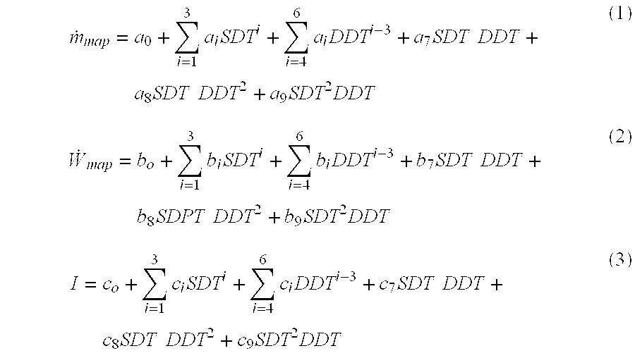
- where the coefficients a i, bi, and ci (i−0 to 9, 30 values) are provided for the compressor and are provided by the manufacturer according to ARI Standard 540-1999. The suction dew point and discharge dew point temperatures in equations (1-3) can be in either ° F. or ° C., using the corresponding set of coefficients.
- If the compressor performance data is not available for the compressor installed in the unit, the data for a similar compressor can be used to approximate the parameters. It is suggested that the compressor data of the similar compressor be of the same technology as the compressor in the HVAC system being tested and of similar capacity.
- For refrigerants that do not present a glide, the suction dew point and the suction bubble point temperatures are exactly the same. In the present document it will be called evaporating temperature (ET). The same is true for the discharge dew point and the discharge bubble point temperatures, in which case it will be called condensing temperature (CT).
- Compressor performance equations, such as equations 1-3, are usually defined for a specific suction line superheat (SH map), typically 20° F. ARI Standard 540-1999 tabulates the suction line superheat and it is equal to 20° F. (for air-conditioning applications). Under actual operating conditions, however, the suction line superheat may be different than the specified value, depending on the working conditions of the cycle. ARI Standard 540-1999 requires that superheat correction values be available when the superheat is other than that specified.
- If the ARI standard superheat corrections are not available, the mass flow rate and the power are corrected using the actual suction line temperature (ST). First, evaluate the suction line design temperature, ST map as
- ST map =ET+SH map (4)
- Assuming that the compressibility of the gas remains constant, the refrigerant density is inversely proportional to the temperature at the suction pressure. Assume also that the correction that applies to the mass flow rate also applies to the input power. Thus, one may write

- where the temperatures must be in an absolute scale (either Kelvin or Rankine).
- The power calculated in equation (6) only accounts for the compressor power.
- C. This step is optional. Use an industry standard amp meter to measure the actual current in all legs leading to the compressor. Alternatively or perhaps in addition to, use an industry standard power meter to measure the power input to the compressor. This technique can be used in single or three phase compressors. Compare the measured current and/or the measured power input to those predicted in step B. If one or more of the current and/or power input measurements deviate significantly (e.g. 10%), then a problem with the
compressor 10 is flagged. Measuring close to predicted current draw and power input indicates that the compressor is operating near expected performance and builds confidence in the accurate use of the mass flow rate ({dot over (m)}) and power ({dot over (W)}) estimates in the subsequent steps. - D. Use the liquid line temperature (LT) and high side pressure (LP) to determine the liquid line subcooling (SC) as
- SC=CT−LT (7)
- If SC is greater than 0° F., then estimate the liquid line refrigerant specific enthalpy (h 3) using the well-known properties of single-phase subcooled refrigerant
- h 3 =h(LT, LP). (8)
- If the refrigerant leaves the condenser as a two-phase mixture, there is no liquid line subcooling, and pressure and temperature are not independent properties, so they can not define the enthalpy. Some other property must be known, such as the quality, x 3, to determine the enthalpy at
state 3. Since this is difficult, a method for estimating h3 that is easy to evaluate is derived. An energy balance over the area of the condenser coil where a two-phase flow exists leads to - {dot over (m)}(h g −h 3)={overscore (U)}A CTOA, (9)
- where h g is the saturated vapor enthalpy at the liquid pressure, {overscore (U)} is the average (over the length) overall heat transfer coefficient, and A is the heat exchanger area where two-phase flow exists. Equation (9) applies when hf<h3<hg (i.e. when a mixture exits the condenser), which may happen when the unit is severely undercharged. For a unit operating in nominal conditions, the refrigerant is a saturated liquid at the end of the two-phase region of the condenser and the same energy balance reads
- {dot over (m)} n h fg,n ={overscore (U)} n A n CTOA n, (10)
- where h fg,n is the latent heat of vaporization at the liquid pressure. From equations (9) and (10), one may write

- If all the variables in equation (11) are known, the enthalpy of the mixture at
state 3 can be calculated. - It is worth noting that the mass flow rate, the average overall heat transfer coefficient and the area of the heat exchanger where a two-phase mixture exists all vary with the operating conditions of the cycle. Unfortunately, the average overall heat transfer coefficient and the area of the heat exchanger where two-phase flow exists are difficult to obtain. As an approximation, consider that the product {overscore (U)}A/{dot over (m)} does not vary significantly. In that case, the enthalpy of the mixture at the exit of the condenser is

- Equation (12) is an approximate solution to determine h 3 when the refrigerant leaves the condenser as a two-phase mixture.
- The value of CTOA n depends on the nominal EER of the equipment. A suggested value, based on a 10-EER unit, is 20° F.
- E. Use the suction line temperature (ST) and pressure (SP) to determine the
suction line 18 superheat (SR) - SH=ST−ET (13)
- If SH is greater than 0° F., then estimate the suction line refrigerant specific enthalpy (h 1) using the well-known properties of single-phase superheated refrigerant
- h 1 =h(ST,SP) (14)
- If there is no suction line superheat, pressure and temperature are not independent properties, so they can not define the enthalpy. Some other property must be known, such as the quality, to determine the enthalpy at
state 1. However, it is important to note that the system should not operate with liquid entering the compressor, because this may cause a catastrophic failure leading to a compressor replacement. - F. Assume there is no enthalpy drop across the expansion device, i.e.,
- h 4 =h 3 (15)
- Estimate capacity ({dot over (Q)}) using the estimates of mass flow rate ({dot over (m)}), the liquid line specific enthalpy (h 4), and the suction line specific enthalpy (h1) as
- {dot over (Q)}={dot over (m)}(h 1 −h 4) (16)
- G. Divide the capacity ({dot over (Q)}) estimated by the power ({dot over (W)}) to determine the COP (coefficient of performance)

- The EER (energy efficiency ratio) is obtained by converting the COP to units of Btu/h/W. These are two common measures of the cycle's operating efficiency.
- H. Estimate the efficiency index by comparing the estimated actual COP to another estimate based on the pressure and temperature measurements that will be used as goals in the service procedure. These measurements represent nominal or desired performance.
- To do this, it is necessary to set a standard for the desired performance under the current conditions. Preferably, the desired performance is set by the operating characteristics of a properly operating (i.e., no faults) vapor compression cycle, under the current driving conditions. Thus, for any driving condition, the desired performance is defined by the values of SP, ST, LP, and LT. Unfortunately, this data is usually not available. An alternative is defining the values of important parameters based on experience, as follows:
- a) Set the evaporating temperature to a desired constant (ET desired). A common value for air-conditioning applications is 40° F. or 45° F.
- b) Set the
suction line 18 superheat to a desired value (SHdesired). For units with fixed orifice expansion devices, use the system's (or a universal) charging chart, commonly provided by equipment manufacturer, to estimate desired superheat for the current outdoor ambient temperature (AMB) and perhaps return air wet bulb temperatures. For units with a TXV, a common value for the superheat is 20° F. - c) Set the liquid line subcooling to a desired value (SC desired). A common value is 12° F.
- d) Set the condensing temperature (CT desired) to a desired number of degrees above the measured outdoor ambient temperature. That temperature difference, which may be a function of the design Energy Efficiency Ratio (EER) rating—higher EER units run with cooler condensers—is called CTOAdesired (Condensing Temperature Over Ambient).
- From the above constraints, the states in the cycle are defined. The suction temperature at desired conditions is
- ST desired =ET desired +SH desired (18)
- From the outdoor air temperature and the CTOA at desired conditions, one may calculate the saturation temperature at the condenser
- CT desired =AMB+CTOA desired (19)
- The liquid temperature can be calculated from the condensing temperature (CT desired) and the subcooling at desired conditions as
- LT desired =CT desired −SC desired (20)
- The suction pressure is only a function of the boiling temperature in the evaporator (ET desired)
- SP desired =P sat(ET desired) (21)
- Finally, the liquid pressure at desired conditions is only a function of the condensing temperature (CT desired)
- LP desired =P sat(CT desired) (22)
- Equations (1) and (2) can be used to determine the refrigerant mass flow rate ({dot over (m)} desired) and power ({dot over (W)}desired) under the desired conditions. The enthalpies can be determined from equations (8) for h3,desired, (14) for h1,desired, and (15) for h4,desired. The capacity at desired conditions is
- {dot over (Q)} desired ={dot over (m)} desired(h 1,desired −h 4,desired) (23)
- The COP at desired conditions can be calculated using

- The capacity index (CI) can be calculated as the ratio of the actual capacity to the capacity at desired conditions

- The efficiency index (EI) can be calculated as the ratio of the actual COP to the COP at desired conditions

- I. The present invention provides a process for estimating the vapor compression cycle operating costs from the knowledge of CI and EI and other important parameters of the equipment, such as:
- NCAP—the nominal capacity of the equipment (or stage, if there is more than one stage in the unit);
- NRT—the nominal equipment annual running time (for example, 1,200 hours),
- SEER—the Seasonal Energy Efficiency Ratio of the unit;
- EP—the price of electricity provided by the utility company (for example, $0.10/kW.h);
- PP—the percentage of power used for purposes other than for compressing the refrigerant gas in the compressor, such as for fans and controls (usually around 20%, so PP=0.2). The power used for purposes other than for compressing the gas is assumed constant.
- Referring now to FIG. 3, the actual capacity is calculated for each stage as
- ACAP=CI NCAP. (27)
- Assume the power consumed for purposes (PCO) other than compressing the gas at the compressor is independent of the operating conditions of the cycle. Therefore, it can be calculated as
- PCO=PP NPC, (28)
- where NPC is the nominal power consumption of the unit, which is
- NPC={dot over (W)} desird +PCO, (29)
- when the unit delivers the nominal capacity NCAP (which is assumed equal to {dot over (Q)} desired). The total power consumption is
- PC={dot over (W)}+PCO. (30)
- From the definitions of EI and CI, and equations (28-30) one can write

- The definition of SEER is the sum of the cooling divided by the sum of the power over the course of one year. Assuming that

- From equations (28-32) the energy consumption can be calculated as

- using the appropriate unit conversions, where necessary.
- The actual running time of the cycle at the actual capacity is equal to

- The estimated operating costs of the unit can be calculated as
- OC=ART EP PC. (35)
- An important feature of this development is a technique that uses compressor performance data provided by manufacturers, with field measurements commonly made by air conditioning and refrigeration technicians. This allows the user to cost effectively estimate the capacity, the coefficient of performance, the efficiency index, and the capacity index of vapor compression cycles in the field. The annual operating costs of the equipment can be estimated from the calculated parameters and can be used to help make better decisions on when service should be provided.
- Compressor performance data is provided for each compressor model in industry standard formats and is intended to support design engineers when applying compressors in system applications. In this application, the data is used to evaluate the performance of an actual vapor compression cycle in the field. The measurements used as inputs for the compressor performance data equations are commonly made in the field.
- Even when the specific compressor equations are not available for the unit being worked on, the present invention can still be employed to determine the capacity index and the efficiency index. Since they are defined as a ratio, a set of compressor performance data equations for a standard compressor, or a representative compressor of a group of technologies with similar performance could be used to estimate these two indices with reasonable accuracy. This significantly extends the use of this invention.
- Although this invention has been described and illustrated by reference to specific embodiments, it will be apparent to those skilled in the art that various changes and modifications may be made which clearly fall within the scope of this invention. The present invention is intended to be protected broadly within the spirit and scope of the appended claims.
Claims (21)
Priority Applications (1)
| Application Number | Priority Date | Filing Date | Title |
|---|---|---|---|
| US10/143,464 US6701725B2 (en) | 2001-05-11 | 2002-05-10 | Estimating operating parameters of vapor compression cycle equipment |
Applications Claiming Priority (2)
| Application Number | Priority Date | Filing Date | Title |
|---|---|---|---|
| US29043301P | 2001-05-11 | 2001-05-11 | |
| US10/143,464 US6701725B2 (en) | 2001-05-11 | 2002-05-10 | Estimating operating parameters of vapor compression cycle equipment |
Publications (2)
| Publication Number | Publication Date |
|---|---|
| US20030019221A1 true US20030019221A1 (en) | 2003-01-30 |
| US6701725B2 US6701725B2 (en) | 2004-03-09 |
Family
ID=26841050
Family Applications (1)
| Application Number | Title | Priority Date | Filing Date |
|---|---|---|---|
| US10/143,464 Expired - Lifetime US6701725B2 (en) | 2001-05-11 | 2002-05-10 | Estimating operating parameters of vapor compression cycle equipment |
Country Status (1)
| Country | Link |
|---|---|
| US (1) | US6701725B2 (en) |
Cited By (69)
| Publication number | Priority date | Publication date | Assignee | Title |
|---|---|---|---|---|
| WO2003089854A1 (en) * | 2002-04-22 | 2003-10-30 | Danfoss A/S | Method for detecting changes a first flux of a heat or cold transport medium in a refrigeration system |
| WO2005003651A3 (en) * | 2003-06-26 | 2005-06-09 | Carrier Corp | Control of refrigeration system |
| US20050166609A1 (en) * | 2002-07-08 | 2005-08-04 | Danfoss A/S | Method and a device for detecting flash gas |
| US20050262857A1 (en) * | 2004-05-25 | 2005-12-01 | Hrejsa Peter B | Apparatus and method for checking conditioning mode of a heat pump system |
| US20060032606A1 (en) * | 2002-10-15 | 2006-02-16 | Claus Thybo | Method and a device for detecting an abnormality of a heat exchanger and the use of such a device |
| WO2006039168A2 (en) * | 2004-09-30 | 2006-04-13 | General Electric Company | Systems and methods for monitoring fouling and slagging in heat transfer devices in coal fired power plants |
| US20060259285A1 (en) * | 2005-04-28 | 2006-11-16 | Vijay Bahel | Cooling system design simulator |
| US20070204635A1 (en) * | 2005-02-24 | 2007-09-06 | Mitsubishi Denki Kabushiki Kaisha | Air Conditioning Apparatus |
| US20080196425A1 (en) * | 2006-11-14 | 2008-08-21 | Temple Keith A | Method for evaluating refrigeration cycle performance |
| US20080196421A1 (en) * | 2006-11-14 | 2008-08-21 | Rossi Todd M | Method for determining evaporator airflow verification |
| US20080209925A1 (en) * | 2006-07-19 | 2008-09-04 | Pham Hung M | Protection and diagnostic module for a refrigeration system |
| US20090030554A1 (en) * | 2007-07-26 | 2009-01-29 | Bean Jr John H | Cooling control device and method |
| US20090092502A1 (en) * | 2007-10-08 | 2009-04-09 | Emerson Climate Technologies, Inc. | Compressor having a power factor correction system and method |
| US20090090113A1 (en) * | 2007-10-05 | 2009-04-09 | Emerson Climate Technologies, Inc. | Compressor assembly having electronics cooling system and method |
| US20090095002A1 (en) * | 2007-10-08 | 2009-04-16 | Emerson Climate Technologies, Inc. | System and method for calculating parameters for a refrigeration system with a variable speed compressor |
| US20090126375A1 (en) * | 2005-10-25 | 2009-05-21 | Masaki Toyoshima | Air conditioner, refrigerant filling method of air conditioner, method for judging refrigerant filling state of air conditioner as well as refrigerant filling and pipe cleaning method of air conditioner |
| US20090151374A1 (en) * | 2005-12-16 | 2009-06-18 | Daikin Industries, Ltd. | Air conditioner |
| US20090241592A1 (en) * | 2007-10-05 | 2009-10-01 | Emerson Climate Technologies, Inc. | Compressor assembly having electronics cooling system and method |
| WO2009151841A1 (en) * | 2008-06-11 | 2009-12-17 | American Power Conversion Corporation | Method and apparatus for cooling |
| US7650758B2 (en) | 2002-04-22 | 2010-01-26 | Danfoss A/S | Method for evaluating a non-measured operating variable in a refrigeration plant |
| EP2196740A2 (en) * | 2008-12-11 | 2010-06-16 | Emerson Electric GmbH & Co. OHG | Method for determining the performance of a cooling machine |
| US20100163634A1 (en) * | 2006-05-18 | 2010-07-01 | Klein Michael J | Systems and methods for monitoring, controlling and limiting usage of utilities |
| US7905098B2 (en) | 2004-04-27 | 2011-03-15 | Emerson Climate Technologies, Inc. | Compressor diagnostic and protection system and method |
| US20110129354A1 (en) * | 2007-10-05 | 2011-06-02 | Emerson Climate Technologies, Inc. | Vibration Protection In A Variable Speed Compressor |
| US20110132019A1 (en) * | 2008-09-01 | 2011-06-09 | Mitsubishi Electronic Corporation | Heat pump apparatus |
| US20110197607A1 (en) * | 2008-11-25 | 2011-08-18 | Mitsubishi Electric Corporation | Refrigerating cycle device |
| US8160827B2 (en) | 2007-11-02 | 2012-04-17 | Emerson Climate Technologies, Inc. | Compressor sensor module |
| US20120174609A1 (en) * | 2009-11-13 | 2012-07-12 | Mitsubishi Heavy Industries, Ltd. | Heat source system |
| US20120216553A1 (en) * | 2009-06-19 | 2012-08-30 | Danfoss A/S | Method for determining wire connections in a vapour compression system |
| US8327656B2 (en) | 2006-08-15 | 2012-12-11 | American Power Conversion Corporation | Method and apparatus for cooling |
| US8393169B2 (en) | 2007-09-19 | 2013-03-12 | Emerson Climate Technologies, Inc. | Refrigeration monitoring system and method |
| US8425287B2 (en) | 2007-01-23 | 2013-04-23 | Schneider Electric It Corporation | In-row air containment and cooling system and method |
| US8424336B2 (en) | 2006-12-18 | 2013-04-23 | Schneider Electric It Corporation | Modular ice storage for uninterruptible chilled water |
| US8448459B2 (en) | 2007-10-08 | 2013-05-28 | Emerson Climate Technologies, Inc. | System and method for evaluating parameters for a refrigeration system with a variable speed compressor |
| US8459053B2 (en) | 2007-10-08 | 2013-06-11 | Emerson Climate Technologies, Inc. | Variable speed compressor protection system and method |
| US8539786B2 (en) | 2007-10-08 | 2013-09-24 | Emerson Climate Technologies, Inc. | System and method for monitoring overheat of a compressor |
| US8672732B2 (en) | 2006-01-19 | 2014-03-18 | Schneider Electric It Corporation | Cooling system and method |
| US8688413B2 (en) | 2010-12-30 | 2014-04-01 | Christopher M. Healey | System and method for sequential placement of cooling resources within data center layouts |
| US20140123693A1 (en) * | 2011-07-07 | 2014-05-08 | Mitsubisha Electric Corporation | Refrigerating and air-conditioning apparatus and method for controlling refrigerating and air-conditioning apparatus |
| US8825451B2 (en) | 2010-12-16 | 2014-09-02 | Schneider Electric It Corporation | System and methods for rack cooling analysis |
| WO2014149174A1 (en) * | 2013-03-15 | 2014-09-25 | Stride Tool, Inc. | Smart hvac manifold system |
| US8964338B2 (en) | 2012-01-11 | 2015-02-24 | Emerson Climate Technologies, Inc. | System and method for compressor motor protection |
| US8974573B2 (en) | 2004-08-11 | 2015-03-10 | Emerson Climate Technologies, Inc. | Method and apparatus for monitoring a refrigeration-cycle system |
| US20150192336A1 (en) * | 2014-01-03 | 2015-07-09 | Woodward, Inc. | Controlling Refrigeration Compression Systems |
| US9140728B2 (en) | 2007-11-02 | 2015-09-22 | Emerson Climate Technologies, Inc. | Compressor sensor module |
| US9285802B2 (en) | 2011-02-28 | 2016-03-15 | Emerson Electric Co. | Residential solutions HVAC monitoring and diagnosis |
| EP2998667A1 (en) * | 2014-09-17 | 2016-03-23 | Hochschule Biberach | Method and apparatus for evaluating the energy efficiency of a refrigeration machine and/or heat pump |
| US9310094B2 (en) | 2007-07-30 | 2016-04-12 | Emerson Climate Technologies, Inc. | Portable method and apparatus for monitoring refrigerant-cycle systems |
| US9310439B2 (en) | 2012-09-25 | 2016-04-12 | Emerson Climate Technologies, Inc. | Compressor having a control and diagnostic module |
| US9451731B2 (en) | 2006-01-19 | 2016-09-20 | Schneider Electric It Corporation | Cooling system and method |
| US9480177B2 (en) | 2012-07-27 | 2016-10-25 | Emerson Climate Technologies, Inc. | Compressor protection module |
| US9519297B1 (en) * | 2010-08-17 | 2016-12-13 | Vytautas K. Virskus | Dynamic differential energy control of hydronic heating or cooling systems |
| US9541907B2 (en) | 2007-10-08 | 2017-01-10 | Emerson Climate Technologies, Inc. | System and method for calibrating parameters for a refrigeration system with a variable speed compressor |
| US9551504B2 (en) | 2013-03-15 | 2017-01-24 | Emerson Electric Co. | HVAC system remote monitoring and diagnosis |
| US9568206B2 (en) | 2006-08-15 | 2017-02-14 | Schneider Electric It Corporation | Method and apparatus for cooling |
| US9638436B2 (en) | 2013-03-15 | 2017-05-02 | Emerson Electric Co. | HVAC system remote monitoring and diagnosis |
| US9765979B2 (en) | 2013-04-05 | 2017-09-19 | Emerson Climate Technologies, Inc. | Heat-pump system with refrigerant charge diagnostics |
| US9803902B2 (en) | 2013-03-15 | 2017-10-31 | Emerson Climate Technologies, Inc. | System for refrigerant charge verification using two condenser coil temperatures |
| US9823632B2 (en) | 2006-09-07 | 2017-11-21 | Emerson Climate Technologies, Inc. | Compressor data module |
| US9830410B2 (en) | 2011-12-22 | 2017-11-28 | Schneider Electric It Corporation | System and method for prediction of temperature values in an electronics system |
| US9952103B2 (en) | 2011-12-22 | 2018-04-24 | Schneider Electric It Corporation | Analysis of effect of transient events on temperature in a data center |
| US9996659B2 (en) | 2009-05-08 | 2018-06-12 | Schneider Electric It Corporation | System and method for arranging equipment in a data center |
| WO2018186623A1 (en) | 2017-04-04 | 2018-10-11 | Samsung Electronics Co., Ltd. | Air conditioner and method for controlling the same |
| WO2019165094A1 (en) * | 2018-02-22 | 2019-08-29 | Schneider Electric USA, Inc. | Detection of efficiency degradation in hvac&r systems |
| CN110741212A (en) * | 2017-04-25 | 2020-01-31 | 艾默生零售解决方案公司 | Dynamic coefficient of performance calculation for refrigeration systems |
| CN111579270A (en) * | 2020-06-28 | 2020-08-25 | 江苏中关村科技产业园节能环保研究有限公司 | Hybrid vehicle heat pump air conditioner test system and test method |
| CN113175733A (en) * | 2021-04-21 | 2021-07-27 | 海信(山东)空调有限公司 | Method for calculating capacity energy efficiency of air conditioner, air conditioner and storage medium |
| US11076507B2 (en) | 2007-05-15 | 2021-07-27 | Schneider Electric It Corporation | Methods and systems for managing facility power and cooling |
| US11206743B2 (en) | 2019-07-25 | 2021-12-21 | Emerson Climate Technolgies, Inc. | Electronics enclosure with heat-transfer element |
Families Citing this family (35)
| Publication number | Priority date | Publication date | Assignee | Title |
|---|---|---|---|---|
| US6658373B2 (en) * | 2001-05-11 | 2003-12-02 | Field Diagnostic Services, Inc. | Apparatus and method for detecting faults and providing diagnostics in vapor compression cycle equipment |
| US20060041335A9 (en) * | 2001-05-11 | 2006-02-23 | Rossi Todd M | Apparatus and method for servicing vapor compression cycle equipment |
| US6973410B2 (en) * | 2001-05-15 | 2005-12-06 | Chillergy Systems, Llc | Method and system for evaluating the efficiency of an air conditioning apparatus |
| FR2840259B1 (en) * | 2002-05-31 | 2004-08-27 | Valeo Climatisation | VEHICLE AIR CONDITIONING SYSTEM PROVIDED WITH AN ELECTRONIC CONTROL DEVICE |
| US6973793B2 (en) * | 2002-07-08 | 2005-12-13 | Field Diagnostic Services, Inc. | Estimating evaporator airflow in vapor compression cycle cooling equipment |
| FR2845035B1 (en) * | 2002-09-27 | 2004-12-24 | Valeo Climatisation | AIR CONDITIONING SYSTEM COMPRISING AN ELECTRONIC CONTROL DEVICE |
| US8463441B2 (en) | 2002-12-09 | 2013-06-11 | Hudson Technologies, Inc. | Method and apparatus for optimizing refrigeration systems |
| US7072727B1 (en) * | 2002-12-16 | 2006-07-04 | Davis Tom G | Method and system for determining heat loss of a building and sizing HVAC equipment |
| NO317847B1 (en) * | 2002-12-23 | 2004-12-20 | Sinvent As | Method for regulating a vapor compression system |
| US20050061008A1 (en) * | 2003-09-24 | 2005-03-24 | A. Ben-Nakhi | Method and apparatus for monitoring an air conditioning / refrigeration unit |
| US7606683B2 (en) * | 2004-01-27 | 2009-10-20 | Emerson Climate Technologies, Inc. | Cooling system design simulator |
| EP1781996A2 (en) * | 2004-08-11 | 2007-05-09 | Lawrence Kates | Method and apparatus for monitoring refrigerant-cycle systems |
| EP1647428B1 (en) * | 2004-10-14 | 2008-06-18 | Ford Global Technologies, LLC | Method for the estimation of the power consumed by the compressor of a refrigerant circuit in a motor vehicle |
| KR100631540B1 (en) * | 2004-10-26 | 2006-10-09 | 엘지전자 주식회사 | Gas-pipes cut-off detection system and method for heat pump type multi air conditioner |
| US8096141B2 (en) * | 2005-01-25 | 2012-01-17 | Trane International Inc. | Superheat control by pressure ratio |
| WO2007027173A1 (en) * | 2005-08-31 | 2007-03-08 | Carrier Corporation | Heat pump water heating system using variable speed compressor |
| US20070151269A1 (en) * | 2005-12-30 | 2007-07-05 | Johnson Controls Technology Company | System and method for level control in a flash tank |
| JP4317878B2 (en) * | 2007-01-05 | 2009-08-19 | 日立アプライアンス株式会社 | Air conditioner and method for judging refrigerant amount |
| US8151583B2 (en) | 2007-08-01 | 2012-04-10 | Trane International Inc. | Expansion valve control system and method for air conditioning apparatus |
| US20090252845A1 (en) * | 2008-04-03 | 2009-10-08 | Southwick Kenneth J | Collider chamber apparatus and method of use |
| US20100187320A1 (en) * | 2009-01-29 | 2010-07-29 | Southwick Kenneth J | Methods and systems for recovering and redistributing heat |
| US8887518B2 (en) | 2010-09-30 | 2014-11-18 | Trane International Inc. | Expansion valve control system and method for air conditioning apparatus |
| TWI583906B (en) * | 2011-12-29 | 2017-05-21 | Chunghwa Telecom Co Ltd | Real - time Analysis Method of Unit Operation Performance of Cold and Heat Energy |
| US10156844B1 (en) | 2012-11-30 | 2018-12-18 | Discovery Sound Technology, Llc | System and method for new equipment configuration and sound monitoring |
| US10145761B1 (en) | 2012-11-30 | 2018-12-04 | Discovery Sound Technology, Llc | Internal arrangement and mount of sound collecting sensors in equipment sound monitoring system |
| US9971667B1 (en) | 2012-11-30 | 2018-05-15 | Discovery Sound Technology, Llc | Equipment sound monitoring system and method |
| US9958190B2 (en) | 2013-01-24 | 2018-05-01 | Advantek Consulting Engineering, Inc. | Optimizing energy efficiency ratio feedback control for direct expansion air-conditioners and heat pumps |
| US9574810B1 (en) | 2013-01-24 | 2017-02-21 | Advantek Consulting Engineering, Inc. | Optimizing energy efficiency ratio feedback control for direct expansion air-conditioners and heat pumps |
| FR3001527B1 (en) * | 2013-01-28 | 2017-08-11 | Schneider Electric Ind Sas | METHOD FOR DIAGNOSING A HEATING, VENTILATION AND AIR CONDITIONING MACHINE |
| ES2834548T3 (en) | 2015-06-24 | 2021-06-17 | Emerson Climate Tech Gmbh | Cross-mapping of components in a refrigeration system |
| US11062062B2 (en) | 2015-11-19 | 2021-07-13 | Carrier Corporation | Diagnostics system for a chiller and method of evaluating performance of a chiller |
| EP3465102B1 (en) | 2016-05-27 | 2020-05-13 | Carrier Corporation | Method for determining reduced airflow in transport refrigeration system |
| US11188292B1 (en) | 2019-04-03 | 2021-11-30 | Discovery Sound Technology, Llc | System and method for customized heterodyning of collected sounds from electromechanical equipment |
| EP3800410A1 (en) * | 2019-10-01 | 2021-04-07 | Siemens Schweiz AG | Optimum operation of a heat exchanger |
| US11800692B2 (en) * | 2020-03-19 | 2023-10-24 | Nooter/Eriksen, Inc. | System and method for data center cooling with carbon dioxide |
Citations (3)
| Publication number | Priority date | Publication date | Assignee | Title |
|---|---|---|---|---|
| US6128910A (en) * | 1997-02-06 | 2000-10-10 | Federal Air Conditioning Technologies, Inc. | Diagnostic unit for an air conditioning system |
| US6438981B1 (en) * | 2000-06-06 | 2002-08-27 | Jay Daniel Whiteside | System for analyzing and comparing current and prospective refrigeration packages |
| US6532754B2 (en) * | 2001-04-25 | 2003-03-18 | American Standard International Inc. | Method of optimizing and rating a variable speed chiller for operation at part load |
Family Cites Families (15)
| Publication number | Priority date | Publication date | Assignee | Title |
|---|---|---|---|---|
| US3082951A (en) | 1953-07-01 | 1963-03-26 | Univ Columbia | Method for calculating performance of refrigeration apparatus |
| US3707851A (en) | 1970-10-28 | 1973-01-02 | Mach Ice Co | Refrigeration system efficiency monitor |
| US3736765A (en) | 1972-01-05 | 1973-06-05 | Gen Electric | Appliance including electric diagnosis means |
| US4114448A (en) | 1976-09-13 | 1978-09-19 | Merritt Joseph E | Servicing apparatus |
| US4161106A (en) | 1977-02-28 | 1979-07-17 | Water Chemists, Inc. | Apparatus and method for determining energy waste in refrigeration units |
| US4186563A (en) | 1978-04-24 | 1980-02-05 | General Electric Company | Cooling efficiency meter circuit for an air conditioner |
| US4217761A (en) | 1978-09-28 | 1980-08-19 | Cornaire James L | Heat pump output indicator |
| US4325223A (en) | 1981-03-16 | 1982-04-20 | Cantley Robert J | Energy management system for refrigeration systems |
| US4432232A (en) | 1982-05-18 | 1984-02-21 | The United States Of America As Represented By The United States Department Of Energy | Device and method for measuring the coefficient of performance of a heat pump |
| US4510576A (en) | 1982-07-26 | 1985-04-09 | Honeywell Inc. | Specific coefficient of performance measuring device |
| SE439063B (en) | 1983-06-02 | 1985-05-28 | Henrik Sven Enstrom | PROCEDURE AND DEVICE FOR TESTING AND PERFORMANCE MONITORING IN HEAT PUMPS AND COOLING INSTALLATIONS |
| US4768346A (en) | 1987-08-26 | 1988-09-06 | Honeywell Inc. | Determining the coefficient of performance of a refrigeration system |
| US4885914A (en) | 1987-10-05 | 1989-12-12 | Honeywell Inc. | Coefficient of performance deviation meter for vapor compression type refrigeration systems |
| US5083438A (en) | 1991-03-01 | 1992-01-28 | Mcmullin Larry D | Chiller monitoring system |
| US6272868B1 (en) | 2000-03-15 | 2001-08-14 | Carrier Corporation | Method and apparatus for indicating condenser coil performance on air-cooled chillers |
-
2002
- 2002-05-10 US US10/143,464 patent/US6701725B2/en not_active Expired - Lifetime
Patent Citations (3)
| Publication number | Priority date | Publication date | Assignee | Title |
|---|---|---|---|---|
| US6128910A (en) * | 1997-02-06 | 2000-10-10 | Federal Air Conditioning Technologies, Inc. | Diagnostic unit for an air conditioning system |
| US6438981B1 (en) * | 2000-06-06 | 2002-08-27 | Jay Daniel Whiteside | System for analyzing and comparing current and prospective refrigeration packages |
| US6532754B2 (en) * | 2001-04-25 | 2003-03-18 | American Standard International Inc. | Method of optimizing and rating a variable speed chiller for operation at part load |
Cited By (153)
| Publication number | Priority date | Publication date | Assignee | Title |
|---|---|---|---|---|
| WO2003089854A1 (en) * | 2002-04-22 | 2003-10-30 | Danfoss A/S | Method for detecting changes a first flux of a heat or cold transport medium in a refrigeration system |
| US20050172647A1 (en) * | 2002-04-22 | 2005-08-11 | Danfoss A/S | Method for detecting changes in a first flux of a heat or cold transport medium in a refrigeration system |
| US7650758B2 (en) | 2002-04-22 | 2010-01-26 | Danfoss A/S | Method for evaluating a non-measured operating variable in a refrigeration plant |
| US7685830B2 (en) * | 2002-04-22 | 2010-03-30 | Danfoss A/S | Method for detecting changes in a first media flow of a heat or cooling medium in a refrigeration system |
| US20050166609A1 (en) * | 2002-07-08 | 2005-08-04 | Danfoss A/S | Method and a device for detecting flash gas |
| US7681407B2 (en) | 2002-07-08 | 2010-03-23 | Danfoss A/S | Method and a device for detecting flash gas |
| US8100167B2 (en) | 2002-10-15 | 2012-01-24 | Danfoss A/S | Method and a device for detecting an abnormality of a heat exchanger, and the use of such a device |
| US20090126899A1 (en) * | 2002-10-15 | 2009-05-21 | Danfoss A/S | Method and a device for detecting an abnormality of a heat exchanger, and the use of such a device |
| US20060032606A1 (en) * | 2002-10-15 | 2006-02-16 | Claus Thybo | Method and a device for detecting an abnormality of a heat exchanger and the use of such a device |
| EP2282142A1 (en) * | 2003-06-26 | 2011-02-09 | Carrier Corporation | Control of refrigeration system |
| WO2005003651A3 (en) * | 2003-06-26 | 2005-06-09 | Carrier Corp | Control of refrigeration system |
| US8474278B2 (en) | 2004-04-27 | 2013-07-02 | Emerson Climate Technologies, Inc. | Compressor diagnostic and protection system and method |
| US10335906B2 (en) | 2004-04-27 | 2019-07-02 | Emerson Climate Technologies, Inc. | Compressor diagnostic and protection system and method |
| US7905098B2 (en) | 2004-04-27 | 2011-03-15 | Emerson Climate Technologies, Inc. | Compressor diagnostic and protection system and method |
| US9669498B2 (en) | 2004-04-27 | 2017-06-06 | Emerson Climate Technologies, Inc. | Compressor diagnostic and protection system and method |
| US9121407B2 (en) | 2004-04-27 | 2015-09-01 | Emerson Climate Technologies, Inc. | Compressor diagnostic and protection system and method |
| US20050262857A1 (en) * | 2004-05-25 | 2005-12-01 | Hrejsa Peter B | Apparatus and method for checking conditioning mode of a heat pump system |
| US9017461B2 (en) | 2004-08-11 | 2015-04-28 | Emerson Climate Technologies, Inc. | Method and apparatus for monitoring a refrigeration-cycle system |
| US9023136B2 (en) | 2004-08-11 | 2015-05-05 | Emerson Climate Technologies, Inc. | Method and apparatus for monitoring a refrigeration-cycle system |
| US9081394B2 (en) | 2004-08-11 | 2015-07-14 | Emerson Climate Technologies, Inc. | Method and apparatus for monitoring a refrigeration-cycle system |
| US9046900B2 (en) | 2004-08-11 | 2015-06-02 | Emerson Climate Technologies, Inc. | Method and apparatus for monitoring refrigeration-cycle systems |
| US9304521B2 (en) | 2004-08-11 | 2016-04-05 | Emerson Climate Technologies, Inc. | Air filter monitoring system |
| US9021819B2 (en) | 2004-08-11 | 2015-05-05 | Emerson Climate Technologies, Inc. | Method and apparatus for monitoring a refrigeration-cycle system |
| US10558229B2 (en) | 2004-08-11 | 2020-02-11 | Emerson Climate Technologies Inc. | Method and apparatus for monitoring refrigeration-cycle systems |
| US9086704B2 (en) | 2004-08-11 | 2015-07-21 | Emerson Climate Technologies, Inc. | Method and apparatus for monitoring a refrigeration-cycle system |
| US9690307B2 (en) | 2004-08-11 | 2017-06-27 | Emerson Climate Technologies, Inc. | Method and apparatus for monitoring refrigeration-cycle systems |
| US8974573B2 (en) | 2004-08-11 | 2015-03-10 | Emerson Climate Technologies, Inc. | Method and apparatus for monitoring a refrigeration-cycle system |
| US7286960B2 (en) | 2004-09-30 | 2007-10-23 | General Electric Company | Systems and methods for monitoring fouling and slagging in heat transfer devices in coal fired power plants |
| WO2006039168A3 (en) * | 2004-09-30 | 2006-09-21 | Gen Electric | Systems and methods for monitoring fouling and slagging in heat transfer devices in coal fired power plants |
| US8046191B2 (en) | 2004-09-30 | 2011-10-25 | General Electric Company | Method for monitoring performance of a heat transfer device |
| US20080015816A1 (en) * | 2004-09-30 | 2008-01-17 | General Electric Company | Monitoring system and method |
| WO2006039168A2 (en) * | 2004-09-30 | 2006-04-13 | General Electric Company | Systems and methods for monitoring fouling and slagging in heat transfer devices in coal fired power plants |
| US7987679B2 (en) * | 2005-02-24 | 2011-08-02 | Mitsubishi Denki Kabushiki Kaisha | Air conditioning apparatus |
| US20070204635A1 (en) * | 2005-02-24 | 2007-09-06 | Mitsubishi Denki Kabushiki Kaisha | Air Conditioning Apparatus |
| US20060259285A1 (en) * | 2005-04-28 | 2006-11-16 | Vijay Bahel | Cooling system design simulator |
| US7908126B2 (en) * | 2005-04-28 | 2011-03-15 | Emerson Climate Technologies, Inc. | Cooling system design simulator |
| US20090126375A1 (en) * | 2005-10-25 | 2009-05-21 | Masaki Toyoshima | Air conditioner, refrigerant filling method of air conditioner, method for judging refrigerant filling state of air conditioner as well as refrigerant filling and pipe cleaning method of air conditioner |
| US8087258B2 (en) * | 2005-10-25 | 2012-01-03 | Mitsubishi Electric Corporation | Air conditioner, refrigerant filling method of air conditioner, method for judging refrigerant filling state of air conditioner as well as refrigerant filling and pipe cleaning method of air conditioner |
| US20090151374A1 (en) * | 2005-12-16 | 2009-06-18 | Daikin Industries, Ltd. | Air conditioner |
| US9303908B2 (en) * | 2005-12-16 | 2016-04-05 | Daikin Industries, Ltd. | Air conditioner |
| US9451731B2 (en) | 2006-01-19 | 2016-09-20 | Schneider Electric It Corporation | Cooling system and method |
| US8672732B2 (en) | 2006-01-19 | 2014-03-18 | Schneider Electric It Corporation | Cooling system and method |
| US20100163634A1 (en) * | 2006-05-18 | 2010-07-01 | Klein Michael J | Systems and methods for monitoring, controlling and limiting usage of utilities |
| US9885507B2 (en) | 2006-07-19 | 2018-02-06 | Emerson Climate Technologies, Inc. | Protection and diagnostic module for a refrigeration system |
| KR101400025B1 (en) * | 2006-07-19 | 2014-05-27 | 에머슨 클리메이트 테크놀로지즈 인코퍼레이티드 | Protection and diagnostic module for a refrigeration system |
| US8590325B2 (en) * | 2006-07-19 | 2013-11-26 | Emerson Climate Technologies, Inc. | Protection and diagnostic module for a refrigeration system |
| US20080209925A1 (en) * | 2006-07-19 | 2008-09-04 | Pham Hung M | Protection and diagnostic module for a refrigeration system |
| US9568206B2 (en) | 2006-08-15 | 2017-02-14 | Schneider Electric It Corporation | Method and apparatus for cooling |
| US8322155B2 (en) | 2006-08-15 | 2012-12-04 | American Power Conversion Corporation | Method and apparatus for cooling |
| US8327656B2 (en) | 2006-08-15 | 2012-12-11 | American Power Conversion Corporation | Method and apparatus for cooling |
| US9115916B2 (en) | 2006-08-15 | 2015-08-25 | Schneider Electric It Corporation | Method of operating a cooling system having one or more cooling units |
| US9823632B2 (en) | 2006-09-07 | 2017-11-21 | Emerson Climate Technologies, Inc. | Compressor data module |
| US20080196425A1 (en) * | 2006-11-14 | 2008-08-21 | Temple Keith A | Method for evaluating refrigeration cycle performance |
| US20080196421A1 (en) * | 2006-11-14 | 2008-08-21 | Rossi Todd M | Method for determining evaporator airflow verification |
| US8024938B2 (en) * | 2006-11-14 | 2011-09-27 | Field Diagnostic Services, Inc. | Method for determining evaporator airflow verification |
| US8424336B2 (en) | 2006-12-18 | 2013-04-23 | Schneider Electric It Corporation | Modular ice storage for uninterruptible chilled water |
| US9080802B2 (en) | 2006-12-18 | 2015-07-14 | Schneider Electric It Corporation | Modular ice storage for uninterruptible chilled water |
| US8425287B2 (en) | 2007-01-23 | 2013-04-23 | Schneider Electric It Corporation | In-row air containment and cooling system and method |
| US11076507B2 (en) | 2007-05-15 | 2021-07-27 | Schneider Electric It Corporation | Methods and systems for managing facility power and cooling |
| US11503744B2 (en) | 2007-05-15 | 2022-11-15 | Schneider Electric It Corporation | Methods and systems for managing facility power and cooling |
| US20090030554A1 (en) * | 2007-07-26 | 2009-01-29 | Bean Jr John H | Cooling control device and method |
| US10352602B2 (en) | 2007-07-30 | 2019-07-16 | Emerson Climate Technologies, Inc. | Portable method and apparatus for monitoring refrigerant-cycle systems |
| US9310094B2 (en) | 2007-07-30 | 2016-04-12 | Emerson Climate Technologies, Inc. | Portable method and apparatus for monitoring refrigerant-cycle systems |
| US8393169B2 (en) | 2007-09-19 | 2013-03-12 | Emerson Climate Technologies, Inc. | Refrigeration monitoring system and method |
| US9651286B2 (en) | 2007-09-19 | 2017-05-16 | Emerson Climate Technologies, Inc. | Refrigeration monitoring system and method |
| US20090090113A1 (en) * | 2007-10-05 | 2009-04-09 | Emerson Climate Technologies, Inc. | Compressor assembly having electronics cooling system and method |
| US20090241592A1 (en) * | 2007-10-05 | 2009-10-01 | Emerson Climate Technologies, Inc. | Compressor assembly having electronics cooling system and method |
| US8849613B2 (en) | 2007-10-05 | 2014-09-30 | Emerson Climate Technologies, Inc. | Vibration protection in a variable speed compressor |
| US8950206B2 (en) | 2007-10-05 | 2015-02-10 | Emerson Climate Technologies, Inc. | Compressor assembly having electronics cooling system and method |
| US9683563B2 (en) | 2007-10-05 | 2017-06-20 | Emerson Climate Technologies, Inc. | Vibration protection in a variable speed compressor |
| US9021823B2 (en) | 2007-10-05 | 2015-05-05 | Emerson Climate Technologies, Inc. | Compressor assembly having electronics cooling system and method |
| US20110129354A1 (en) * | 2007-10-05 | 2011-06-02 | Emerson Climate Technologies, Inc. | Vibration Protection In A Variable Speed Compressor |
| US9057549B2 (en) | 2007-10-08 | 2015-06-16 | Emerson Climate Technologies, Inc. | System and method for monitoring compressor floodback |
| US8459053B2 (en) | 2007-10-08 | 2013-06-11 | Emerson Climate Technologies, Inc. | Variable speed compressor protection system and method |
| US20090092502A1 (en) * | 2007-10-08 | 2009-04-09 | Emerson Climate Technologies, Inc. | Compressor having a power factor correction system and method |
| US9541907B2 (en) | 2007-10-08 | 2017-01-10 | Emerson Climate Technologies, Inc. | System and method for calibrating parameters for a refrigeration system with a variable speed compressor |
| US9494158B2 (en) | 2007-10-08 | 2016-11-15 | Emerson Climate Technologies, Inc. | Variable speed compressor protection system and method |
| US20090095002A1 (en) * | 2007-10-08 | 2009-04-16 | Emerson Climate Technologies, Inc. | System and method for calculating parameters for a refrigeration system with a variable speed compressor |
| US9494354B2 (en) | 2007-10-08 | 2016-11-15 | Emerson Climate Technologies, Inc. | System and method for calculating parameters for a refrigeration system with a variable speed compressor |
| US9476625B2 (en) | 2007-10-08 | 2016-10-25 | Emerson Climate Technologies, Inc. | System and method for monitoring compressor floodback |
| US10077774B2 (en) | 2007-10-08 | 2018-09-18 | Emerson Climate Technologies, Inc. | Variable speed compressor protection system and method |
| US8539786B2 (en) | 2007-10-08 | 2013-09-24 | Emerson Climate Technologies, Inc. | System and method for monitoring overheat of a compressor |
| US8418483B2 (en) * | 2007-10-08 | 2013-04-16 | Emerson Climate Technologies, Inc. | System and method for calculating parameters for a refrigeration system with a variable speed compressor |
| US8448459B2 (en) | 2007-10-08 | 2013-05-28 | Emerson Climate Technologies, Inc. | System and method for evaluating parameters for a refrigeration system with a variable speed compressor |
| US10962009B2 (en) | 2007-10-08 | 2021-03-30 | Emerson Climate Technologies, Inc. | Variable speed compressor protection system and method |
| US8335657B2 (en) | 2007-11-02 | 2012-12-18 | Emerson Climate Technologies, Inc. | Compressor sensor module |
| US8160827B2 (en) | 2007-11-02 | 2012-04-17 | Emerson Climate Technologies, Inc. | Compressor sensor module |
| US10458404B2 (en) | 2007-11-02 | 2019-10-29 | Emerson Climate Technologies, Inc. | Compressor sensor module |
| US9194894B2 (en) | 2007-11-02 | 2015-11-24 | Emerson Climate Technologies, Inc. | Compressor sensor module |
| US9140728B2 (en) | 2007-11-02 | 2015-09-22 | Emerson Climate Technologies, Inc. | Compressor sensor module |
| WO2009151841A1 (en) * | 2008-06-11 | 2009-12-17 | American Power Conversion Corporation | Method and apparatus for cooling |
| CN103175356A (en) * | 2008-06-11 | 2013-06-26 | 美国能量变换公司 | Method and apparatus for cooling |
| US20110132019A1 (en) * | 2008-09-01 | 2011-06-09 | Mitsubishi Electronic Corporation | Heat pump apparatus |
| US8745999B2 (en) * | 2008-09-01 | 2014-06-10 | Mitsubishi Electric Corporation | Heat pump apparatus |
| US20110197607A1 (en) * | 2008-11-25 | 2011-08-18 | Mitsubishi Electric Corporation | Refrigerating cycle device |
| US9222694B2 (en) * | 2008-11-25 | 2015-12-29 | Mitsubishi Electric Corporation | Refrigerating cycle device |
| US20100153057A1 (en) * | 2008-12-11 | 2010-06-17 | Emerson Electric Gmbh & Co. Ohg | Method for determination of the coefficient of performanace of a refrigerating machine |
| EP2196740A3 (en) * | 2008-12-11 | 2010-09-15 | Emerson Electric GmbH & Co. OHG | Method for determining the performance of a cooling machine |
| EP2196740A2 (en) * | 2008-12-11 | 2010-06-16 | Emerson Electric GmbH & Co. OHG | Method for determining the performance of a cooling machine |
| US8775123B2 (en) * | 2008-12-11 | 2014-07-08 | Emerson Climate Technologies Gmbh | Method for determination of the coefficient of performanace of a refrigerating machine |
| DE102008061631A1 (en) * | 2008-12-11 | 2010-06-17 | Emerson Electric Gmbh & Co. Ohg | Method for determining the coefficient of performance of a refrigerating machine |
| US10614194B2 (en) | 2009-05-08 | 2020-04-07 | Schneider Electric It Corporation | System and method for arranging equipment in a data center |
| US9996659B2 (en) | 2009-05-08 | 2018-06-12 | Schneider Electric It Corporation | System and method for arranging equipment in a data center |
| US9416999B2 (en) * | 2009-06-19 | 2016-08-16 | Danfoss A/S | Method for determining wire connections in a vapour compression system |
| US20120216553A1 (en) * | 2009-06-19 | 2012-08-30 | Danfoss A/S | Method for determining wire connections in a vapour compression system |
| US9206994B2 (en) * | 2009-11-13 | 2015-12-08 | Mitsubishi Heavy Industries, Ltd. | Heat source system |
| US20120174609A1 (en) * | 2009-11-13 | 2012-07-12 | Mitsubishi Heavy Industries, Ltd. | Heat source system |
| US9519297B1 (en) * | 2010-08-17 | 2016-12-13 | Vytautas K. Virskus | Dynamic differential energy control of hydronic heating or cooling systems |
| US8825451B2 (en) | 2010-12-16 | 2014-09-02 | Schneider Electric It Corporation | System and methods for rack cooling analysis |
| US8688413B2 (en) | 2010-12-30 | 2014-04-01 | Christopher M. Healey | System and method for sequential placement of cooling resources within data center layouts |
| US10884403B2 (en) | 2011-02-28 | 2021-01-05 | Emerson Electric Co. | Remote HVAC monitoring and diagnosis |
| US9703287B2 (en) | 2011-02-28 | 2017-07-11 | Emerson Electric Co. | Remote HVAC monitoring and diagnosis |
| US10234854B2 (en) | 2011-02-28 | 2019-03-19 | Emerson Electric Co. | Remote HVAC monitoring and diagnosis |
| US9285802B2 (en) | 2011-02-28 | 2016-03-15 | Emerson Electric Co. | Residential solutions HVAC monitoring and diagnosis |
| US20140123693A1 (en) * | 2011-07-07 | 2014-05-08 | Mitsubisha Electric Corporation | Refrigerating and air-conditioning apparatus and method for controlling refrigerating and air-conditioning apparatus |
| US9453671B2 (en) * | 2011-07-07 | 2016-09-27 | Mitsubishi Electric Corporation | Refrigerating and air-conditioning apparatus and method for controlling refrigerating and air-conditioning apparatus |
| US9830410B2 (en) | 2011-12-22 | 2017-11-28 | Schneider Electric It Corporation | System and method for prediction of temperature values in an electronics system |
| US9952103B2 (en) | 2011-12-22 | 2018-04-24 | Schneider Electric It Corporation | Analysis of effect of transient events on temperature in a data center |
| US9876346B2 (en) | 2012-01-11 | 2018-01-23 | Emerson Climate Technologies, Inc. | System and method for compressor motor protection |
| US8964338B2 (en) | 2012-01-11 | 2015-02-24 | Emerson Climate Technologies, Inc. | System and method for compressor motor protection |
| US9590413B2 (en) | 2012-01-11 | 2017-03-07 | Emerson Climate Technologies, Inc. | System and method for compressor motor protection |
| US10028399B2 (en) | 2012-07-27 | 2018-07-17 | Emerson Climate Technologies, Inc. | Compressor protection module |
| US10485128B2 (en) | 2012-07-27 | 2019-11-19 | Emerson Climate Technologies, Inc. | Compressor protection module |
| US9480177B2 (en) | 2012-07-27 | 2016-10-25 | Emerson Climate Technologies, Inc. | Compressor protection module |
| US9310439B2 (en) | 2012-09-25 | 2016-04-12 | Emerson Climate Technologies, Inc. | Compressor having a control and diagnostic module |
| US9762168B2 (en) | 2012-09-25 | 2017-09-12 | Emerson Climate Technologies, Inc. | Compressor having a control and diagnostic module |
| US9803902B2 (en) | 2013-03-15 | 2017-10-31 | Emerson Climate Technologies, Inc. | System for refrigerant charge verification using two condenser coil temperatures |
| US9638436B2 (en) | 2013-03-15 | 2017-05-02 | Emerson Electric Co. | HVAC system remote monitoring and diagnosis |
| US10274945B2 (en) | 2013-03-15 | 2019-04-30 | Emerson Electric Co. | HVAC system remote monitoring and diagnosis |
| WO2014149174A1 (en) * | 2013-03-15 | 2014-09-25 | Stride Tool, Inc. | Smart hvac manifold system |
| US9551504B2 (en) | 2013-03-15 | 2017-01-24 | Emerson Electric Co. | HVAC system remote monitoring and diagnosis |
| US10775084B2 (en) | 2013-03-15 | 2020-09-15 | Emerson Climate Technologies, Inc. | System for refrigerant charge verification |
| US10488090B2 (en) | 2013-03-15 | 2019-11-26 | Emerson Climate Technologies, Inc. | System for refrigerant charge verification |
| US10452061B2 (en) | 2013-03-15 | 2019-10-22 | North Park Innovations Group, Inc. | Smart HVAC manifold system |
| US10060636B2 (en) | 2013-04-05 | 2018-08-28 | Emerson Climate Technologies, Inc. | Heat pump system with refrigerant charge diagnostics |
| US9765979B2 (en) | 2013-04-05 | 2017-09-19 | Emerson Climate Technologies, Inc. | Heat-pump system with refrigerant charge diagnostics |
| US10443863B2 (en) | 2013-04-05 | 2019-10-15 | Emerson Climate Technologies, Inc. | Method of monitoring charge condition of heat pump system |
| US20150192336A1 (en) * | 2014-01-03 | 2015-07-09 | Woodward, Inc. | Controlling Refrigeration Compression Systems |
| US9696074B2 (en) * | 2014-01-03 | 2017-07-04 | Woodward, Inc. | Controlling refrigeration compression systems |
| EP2998667A1 (en) * | 2014-09-17 | 2016-03-23 | Hochschule Biberach | Method and apparatus for evaluating the energy efficiency of a refrigeration machine and/or heat pump |
| WO2018186623A1 (en) | 2017-04-04 | 2018-10-11 | Samsung Electronics Co., Ltd. | Air conditioner and method for controlling the same |
| KR20180112550A (en) * | 2017-04-04 | 2018-10-12 | 삼성전자주식회사 | Air conditioner and method for controlling the same |
| EP3593057A4 (en) * | 2017-04-04 | 2020-06-10 | Samsung Electronics Co., Ltd. | Air conditioner and method for controlling the same |
| US10955177B2 (en) | 2017-04-04 | 2021-03-23 | Samsung Electronics Co., Ltd. | Air conditioner and method for controlling the same |
| CN108758903A (en) * | 2017-04-04 | 2018-11-06 | 三星电子株式会社 | Air-conditioning and its control method |
| KR102367077B1 (en) * | 2017-04-04 | 2022-02-24 | 삼성전자주식회사 | Air conditioner and method for controlling the same |
| CN110741212B (en) * | 2017-04-25 | 2021-09-07 | 艾默生零售解决方案公司 | Dynamic coefficient of performance calculation for refrigeration systems |
| CN110741212A (en) * | 2017-04-25 | 2020-01-31 | 艾默生零售解决方案公司 | Dynamic coefficient of performance calculation for refrigeration systems |
| WO2019165094A1 (en) * | 2018-02-22 | 2019-08-29 | Schneider Electric USA, Inc. | Detection of efficiency degradation in hvac&r systems |
| US11206743B2 (en) | 2019-07-25 | 2021-12-21 | Emerson Climate Technolgies, Inc. | Electronics enclosure with heat-transfer element |
| US11706899B2 (en) | 2019-07-25 | 2023-07-18 | Emerson Climate Technologies, Inc. | Electronics enclosure with heat-transfer element |
| CN111579270A (en) * | 2020-06-28 | 2020-08-25 | 江苏中关村科技产业园节能环保研究有限公司 | Hybrid vehicle heat pump air conditioner test system and test method |
| CN113175733A (en) * | 2021-04-21 | 2021-07-27 | 海信(山东)空调有限公司 | Method for calculating capacity energy efficiency of air conditioner, air conditioner and storage medium |
Also Published As
| Publication number | Publication date |
|---|---|
| US6701725B2 (en) | 2004-03-09 |
Similar Documents
| Publication | Publication Date | Title |
|---|---|---|
| US6701725B2 (en) | Estimating operating parameters of vapor compression cycle equipment | |
| US6973793B2 (en) | Estimating evaporator airflow in vapor compression cycle cooling equipment | |
| US7079967B2 (en) | Apparatus and method for detecting faults and providing diagnostics in vapor compression cycle equipment | |
| US10775084B2 (en) | System for refrigerant charge verification | |
| JP2997487B2 (en) | Refrigeration apparatus and method for indicating amount of refrigerant in refrigeration apparatus | |
| US20060041335A9 (en) | Apparatus and method for servicing vapor compression cycle equipment | |
| KR100903815B1 (en) | Air conditioner coolant amount judgment apparatus | |
| US8583384B2 (en) | Method for calculating target temperature split, target superheat, target enthalpy, and energy efficiency ratio improvements for air conditioners and heat pumps in cooling mode | |
| JP4462096B2 (en) | Air conditioner | |
| JP2001280770A (en) | Method and apparatus for deciding operating state of condenser coil of refrigerating system | |
| CN113175733B (en) | Method for calculating capacity energy efficiency of air conditioner, air conditioner and storage medium | |
| Li et al. | Virtual refrigerant pressure sensors for use in monitoring and fault diagnosis of vapor-compression equipment | |
| CN113175738B (en) | Method for calculating capacity energy efficiency of air conditioner, computer storage medium and air conditioner | |
| CN113175735B (en) | Method for calculating capacity energy efficiency of air conditioner, computer storage medium and air conditioner | |
| JPH08121917A (en) | Refrigerant quantity determining device | |
| JP2006292214A (en) | Addition method of refrigerant amount determining function of air conditioner, and air conditioner | |
| JP5369953B2 (en) | Multi-room air conditioner performance calculator | |
| Wichman et al. | Fault detection and diagnostics for commercial coolers and freezers | |
| CN112955702A (en) | Diagnostics for refrigerant composition verification | |
| CN113175736B (en) | Method for calculating capacity energy efficiency of air conditioner, air conditioner and storage medium | |
| CN113175734B (en) | Method for calculating capacity energy efficiency of air conditioner, computer storage medium and air conditioner | |
| CN113175737B (en) | Method for calculating capacity energy efficiency of air conditioner, air conditioner and storage medium | |
| Levins et al. | Modeled and measured effects of compressor downsizing in an existing air conditioner/heat pump in the cooling mode | |
| Shen et al. | Modeling Improvements for Air-Source Heat Pumps Using Different Expansion Devices at Varied Charge Levels--Part II. | |
| Shen et al. | Modeling of Compressors and Expansion Devices With Two-Phase Refrigerant Inlet Conditions |
Legal Events
| Date | Code | Title | Description |
|---|---|---|---|
| AS | Assignment |
Owner name: FIELD DIAGNOSTIC SERVICES, INC., PENNSYLVANIA Free format text: ASSIGNMENT OF ASSIGNORS INTEREST;ASSIGNORS:ROSSI, TODD M.;DOUGLAS, JONATHAN D.;BIANCHI, MARCUS V.A.;REEL/FRAME:013277/0844 Effective date: 20020830 |
|
| FEPP | Fee payment procedure |
Free format text: PAYOR NUMBER ASSIGNED (ORIGINAL EVENT CODE: ASPN); ENTITY STATUS OF PATENT OWNER: SMALL ENTITY |
|
| STCF | Information on status: patent grant |
Free format text: PATENTED CASE |
|
| CC | Certificate of correction | ||
| FPAY | Fee payment |
Year of fee payment: 4 |
|
| AS | Assignment |
Owner name: BLUE HILL INVESTMENT PARTNERS, L.P., PENNSYLVANIA Free format text: SECURITY AGREEMENT;ASSIGNOR:FIELD DIAGNOSTIC SERVICES, INC.;REEL/FRAME:019795/0356 Effective date: 20070822 |
|
| FPAY | Fee payment |
Year of fee payment: 8 |
|
| FPAY | Fee payment |
Year of fee payment: 12 |
|
| AS | Assignment |
Owner name: FLOW CAPITAL CORP., CANADA Free format text: SECURITY INTEREST;ASSIGNOR:FIELD DIAGNOSTIC SERVICES, INC.;REEL/FRAME:048285/0942 Effective date: 20190122 |
|
| AS | Assignment |
Owner name: NGRAIN (CANADA) CORPORATION, CALIFORNIA Free format text: RELEASE BY SECURED PARTY;ASSIGNOR:FLOW CAPITAL CORP.;REEL/FRAME:049937/0367 Effective date: 20190801 Owner name: FIELD DIAGNOSTIC SERVICES, INC., CALIFORNIA Free format text: RELEASE BY SECURED PARTY;ASSIGNOR:FLOW CAPITAL CORP.;REEL/FRAME:049937/0367 Effective date: 20190801 |
|
| AS | Assignment |
Owner name: FIERA PRIVATE DEBT FUND VI LP, CANADA Free format text: SECURITY INTEREST;ASSIGNOR:FIELD DIAGNOSTIC SERVICES, INC.;REEL/FRAME:058042/0229 Effective date: 20211105 |
|
| AS | Assignment |
Owner name: AMERICAN TRUST INVESTMENT SERVICES, INC., ILLINOIS Free format text: SECURITY INTEREST;ASSIGNORS:MCLOUD TECHNOLOGIES CORP.;MCLOUD TECHNOLOGIES (USA) INC.;FIELD DIAGNOSTICS SERVICES, INC;AND OTHERS;REEL/FRAME:063364/0170 Effective date: 20230413 |
|
| AS | Assignment |
Owner name: MCLOUD TECHNOLOGIES (USA) INC., CALIFORNIA Free format text: ASSIGNMENT OF ASSIGNORS INTEREST;ASSIGNOR:FIELD DIAGNOSTIC SERVICES, INC.;REEL/FRAME:064513/0847 Effective date: 20230803 |