US20030031380A1 - Method and apparatus for visualization and manipulation of real 3-D objects in networked environments - Google Patents
Method and apparatus for visualization and manipulation of real 3-D objects in networked environments Download PDFInfo
- Publication number
- US20030031380A1 US20030031380A1 US09/873,056 US87305601A US2003031380A1 US 20030031380 A1 US20030031380 A1 US 20030031380A1 US 87305601 A US87305601 A US 87305601A US 2003031380 A1 US2003031380 A1 US 2003031380A1
- Authority
- US
- United States
- Prior art keywords
- video
- images
- sequence
- viewing
- database
- Prior art date
- Legal status (The legal status is an assumption and is not a legal conclusion. Google has not performed a legal analysis and makes no representation as to the accuracy of the status listed.)
- Granted
Links
Images


Classifications
-
- G—PHYSICS
- G06—COMPUTING; CALCULATING OR COUNTING
- G06T—IMAGE DATA PROCESSING OR GENERATION, IN GENERAL
- G06T17/00—Three dimensional [3D] modelling, e.g. data description of 3D objects
-
- H—ELECTRICITY
- H04—ELECTRIC COMMUNICATION TECHNIQUE
- H04N—PICTORIAL COMMUNICATION, e.g. TELEVISION
- H04N21/00—Selective content distribution, e.g. interactive television or video on demand [VOD]
- H04N21/40—Client devices specifically adapted for the reception of or interaction with content, e.g. set-top-box [STB]; Operations thereof
- H04N21/41—Structure of client; Structure of client peripherals
- H04N21/414—Specialised client platforms, e.g. receiver in car or embedded in a mobile appliance
- H04N21/4143—Specialised client platforms, e.g. receiver in car or embedded in a mobile appliance embedded in a Personal Computer [PC]
-
- G—PHYSICS
- G06—COMPUTING; CALCULATING OR COUNTING
- G06T—IMAGE DATA PROCESSING OR GENERATION, IN GENERAL
- G06T15/00—3D [Three Dimensional] image rendering
-
- H—ELECTRICITY
- H04—ELECTRIC COMMUNICATION TECHNIQUE
- H04N—PICTORIAL COMMUNICATION, e.g. TELEVISION
- H04N19/00—Methods or arrangements for coding, decoding, compressing or decompressing digital video signals
- H04N19/60—Methods or arrangements for coding, decoding, compressing or decompressing digital video signals using transform coding
- H04N19/61—Methods or arrangements for coding, decoding, compressing or decompressing digital video signals using transform coding in combination with predictive coding
-
- H—ELECTRICITY
- H04—ELECTRIC COMMUNICATION TECHNIQUE
- H04N—PICTORIAL COMMUNICATION, e.g. TELEVISION
- H04N21/00—Selective content distribution, e.g. interactive television or video on demand [VOD]
- H04N21/20—Servers specifically adapted for the distribution of content, e.g. VOD servers; Operations thereof
- H04N21/21—Server components or server architectures
- H04N21/218—Source of audio or video content, e.g. local disk arrays
- H04N21/21805—Source of audio or video content, e.g. local disk arrays enabling multiple viewpoints, e.g. using a plurality of cameras
-
- H—ELECTRICITY
- H04—ELECTRIC COMMUNICATION TECHNIQUE
- H04N—PICTORIAL COMMUNICATION, e.g. TELEVISION
- H04N21/00—Selective content distribution, e.g. interactive television or video on demand [VOD]
- H04N21/20—Servers specifically adapted for the distribution of content, e.g. VOD servers; Operations thereof
- H04N21/23—Processing of content or additional data; Elementary server operations; Server middleware
- H04N21/234—Processing of video elementary streams, e.g. splicing of video streams, manipulating MPEG-4 scene graphs
- H04N21/2343—Processing of video elementary streams, e.g. splicing of video streams, manipulating MPEG-4 scene graphs involving reformatting operations of video signals for distribution or compliance with end-user requests or end-user device requirements
- H04N21/234381—Processing of video elementary streams, e.g. splicing of video streams, manipulating MPEG-4 scene graphs involving reformatting operations of video signals for distribution or compliance with end-user requests or end-user device requirements by altering the temporal resolution, e.g. decreasing the frame rate by frame skipping
-
- H—ELECTRICITY
- H04—ELECTRIC COMMUNICATION TECHNIQUE
- H04N—PICTORIAL COMMUNICATION, e.g. TELEVISION
- H04N21/00—Selective content distribution, e.g. interactive television or video on demand [VOD]
- H04N21/60—Network structure or processes for video distribution between server and client or between remote clients; Control signalling between clients, server and network components; Transmission of management data between server and client, e.g. sending from server to client commands for recording incoming content stream; Communication details between server and client
- H04N21/61—Network physical structure; Signal processing
- H04N21/6106—Network physical structure; Signal processing specially adapted to the downstream path of the transmission network
- H04N21/6125—Network physical structure; Signal processing specially adapted to the downstream path of the transmission network involving transmission via Internet
-
- H—ELECTRICITY
- H04—ELECTRIC COMMUNICATION TECHNIQUE
- H04N—PICTORIAL COMMUNICATION, e.g. TELEVISION
- H04N21/00—Selective content distribution, e.g. interactive television or video on demand [VOD]
- H04N21/60—Network structure or processes for video distribution between server and client or between remote clients; Control signalling between clients, server and network components; Transmission of management data between server and client, e.g. sending from server to client commands for recording incoming content stream; Communication details between server and client
- H04N21/65—Transmission of management data between client and server
- H04N21/658—Transmission by the client directed to the server
- H04N21/6587—Control parameters, e.g. trick play commands, viewpoint selection
-
- H—ELECTRICITY
- H04—ELECTRIC COMMUNICATION TECHNIQUE
- H04N—PICTORIAL COMMUNICATION, e.g. TELEVISION
- H04N7/00—Television systems
- H04N7/16—Analogue secrecy systems; Analogue subscription systems
- H04N7/173—Analogue secrecy systems; Analogue subscription systems with two-way working, e.g. subscriber sending a programme selection signal
- H04N7/17309—Transmission or handling of upstream communications
- H04N7/17336—Handling of requests in head-ends
-
- G—PHYSICS
- G06—COMPUTING; CALCULATING OR COUNTING
- G06T—IMAGE DATA PROCESSING OR GENERATION, IN GENERAL
- G06T2200/00—Indexing scheme for image data processing or generation, in general
- G06T2200/16—Indexing scheme for image data processing or generation, in general involving adaptation to the client's capabilities
Definitions
- This invention relates generally to visualization. More particularly, this invention relates to visualization and manipulation of a real 3-D object using image acquisition and video compression.
- the modeling step involves the extraction and storage of parameters describing the object.
- the rendering step renders the image (preferably in real-time) based on the stored object parameters as the user requests a certain view of the object.
- the modeling step may be performed off-line and thus is amenable to extremely complicated algorithms, the rendering step must be performed real-time for realistic manipulation of objects.
- the rendering process for natural complex objects cannot be performed on the client side, as most clients on the Web are PCs with limited computational bandwidth.
- the placement of the rendering step on the server side e.g., a supercomputer does not solve the problem either, as it will limit the number of simultaneous rendering requests the server may be able to service.
- an object of the present invention is to provide a new visualization technique that is computationally efficient for use in network environments.
- Another object is to provide real-time manipulation of a real 3-D object during visualization over a network such as the Internet.
- the present invention replaces the modeling step with an image acquisition step and a rendering step with a simple video decompression step. All computationally demanding portions (as well as manual efforts in extracting the modeling parameters) that exist in conventional visualization approaches have been eliminated. As such, the user may view and manipulate natural real 3-D objects in real time over the Internet.
- the server (with the 3-D data) in this case simply transmits the data to the requesting client.
- FIG. 1 shows the geometry of an image acquisition device.
- FIG. 2 is an illustration of a “fuzz ball’, a collection of all rays from the camera position to the origin.
- FIGS. 3A and 3B are illustrations of image capture locations for a slice sampling strategy.
- FIGS. 4A and 4B are illustrations of image capture locations for an anisotropic spiral sampling strategy.
- FIGS. 5A and 5B are illustrations of image capture locations for an isotropic spiral sampling strategy.
- FIG. 6 is a photograph of a 3-D imaging capture system.
- FIG. 7 is a screen showing the main window of the 3-D image editor software.
- FIGS. 8A and 8B are illustrations of controls in the display software in the NEWS and AVIATION modes.
- FIG. 9 is a process chart for a one-stop service for 3-D imaging and visualization.
- FIG. 10 is a block diagram of the system offering a total service for 3-D visualization over the Internet.
- FIGS. 11 and 12 are the flowchart of the software that implements the 3-D Image Viewer.
- FIG. 1 shows the geometry of the image acquisition device.
- the object 100 is placed in the center (origin) and the camera 101 rotates about the object to capture images at various prescribed angle ⁇ 102 and ⁇ 103 at distance R 104 , where ⁇ 102 is an azimuth in the horizontal plane and ⁇ 103 is an elevation from the horizontal plane.
- ⁇ 102 is an azimuth in the horizontal plane
- ⁇ 103 is an elevation from the horizontal plane.
- the object in order to reproduce the image of the object at a particular view angle that the user may request, the object must be imaged from “all possible view angles”.
- the definition of “all possible view angles” can be realized by drawing a subset of all possible rays (“all possible view angles”) from the origin.
- FIG. 2 shows a “fuzz-ball” formed by all such rays viewed together.
- the ray spacing basically controls the viewing resolution, in the corresponding direction ⁇ and ⁇ . The viewing resolution determines the smoothness while rotating the view angle, by changing ⁇ and ⁇ by the mouse action.
- the camera will be required take pictures at a point from each of the rays pointing towards the center, the camera will be required move about a surface enclosing the object.
- the optimal surface in the sense of minimizing the distance traveled by the camera, is therefore the surface enclosing the object with the smallest surface area.
- the optimal surface is a sphere with radius R. If the object is imaged from all points on the surface (with camera pointing towards the origin), this amounts to having imaged the object from “all possible view angles”.
- the parameterized angles e.g., ⁇ (t) and ⁇ (t), 0 ⁇ t ⁇ T, where T is the total capture time, dictate the camera path.
- FIG. 3A shows one possible path that the camera may traverse to cover the sphere with radius R in a single sweep.
- FIG. 3B shows the 3-D plot of FIG. 3A mapped to a flat surface using the Sanson projection, often used for geographical mapping applications. The dots in the figure indicate the image capture locations where the images are acquired with the camera pointing directly towards the origin.
- N ⁇ and N ⁇ denote the average (or exact) number of frames captured within the range [0,2 ⁇ ) and [0, ⁇ ], respectively. Note that N ⁇ and N ⁇ need not be integers. Then, the total number of acquired images N ⁇ N ⁇ N ⁇ .
- FIG. 3A and FIG. 3B show the result of using capture locations of Eqns. (1) and (2).
- T ⁇ is the time taken for the camera to rotate one revolution in ⁇ direction.
- FIG. 3A and FIG. 3B show the capture angles where the dots indicate the actual image capture positions of the camera.
- FIG. 3A shows the 3-D trajectory (line) which is marked (dots) with all image capture locations
- FIG. 3B shows all capture locations mapped using the Sanson projection (see text).
- N N ⁇ N ⁇
- FIG. 4A and FIG. 4B show the resulting image capture locations with the same parameters as in FIG. 3A and FIG. 3B.
- FIG. 4A and 4B show the 3-D trajectory and the Sanson projection of the image capture points.
- the slice sampling strategy there are a total of 256 frames captured with this method.
- One approach would be to keep the differential distance dr (vector) to be constant in the parameter t, and sample the camera position vector r at equal intervals of the parameter t. Then, adjacent capture locations will be “equally spaced” along the path. However, the spacing along the vertical direction, ⁇ , may differ depending on the actual angle ⁇ . That is, the spacing along the vertical direction would vary as sin ( ⁇ ). Thus, designing the differential distance dr to be constant in t will not provide isotropic image capture points. An alternative solution is sought.
- ⁇ ⁇ ( t ) ⁇ o + 2 ⁇ ⁇ ⁇ ⁇ t T ⁇ , 0 ⁇ t ⁇ T ( 11 )
- ⁇ ⁇ ( t ) ⁇ o + ⁇ ⁇ ⁇ t T , 0 ⁇ t ⁇ T ( 12 )
- FIG. 5A and FIG. 5B show the resulting image capture locations. Note that the capture positions are equally spaced visually, which in effect offers isotropic viewing resolution.
- FIGS. 3A, 3B, 4 A, 4 B FIG. 5A shows the 3-D trajectory (line), which is marked (dots) with all image capture locations, and FIG. 5B shows all capture locations mapped using the Sanson projection (see text).
- the image acquisition device will store the following into a centralized (or distributed) database for later access over the network:
- Image sequence f(k),k 0,1,K,N ⁇ 1, namely the compressed video
- FIG. 6 is a photograph of the 3-D image capture hardware of the present invention.
- the two motors 110 , 111 control the two angles that determine that position of the camera 112 .
- the camera moves along the vertical C-arm 113 (direction ⁇ ) while the turntable 114 controls ⁇ .
- the device captures the image sequence while recording the two angles, ⁇ and ⁇ , generated by the two encoders attached to the two motors.
- the carriage 115 which is powered by a motor, moves along the vertical C-arm equipped with a timing belt 116 .
- the two motors 110 , 111 controlling ⁇ (turntable) and ⁇ (camera carriage) are pre-programmed from the operator console 117 (PC) to run in a prescribed manner.
- FIG. 7 shows the 3-D image editor.
- the editor has three main panes: the Sanson projection pane (top left) shows the actual image capture positions (dots) using the Sanson projection; the 3-D view pane (bottom left), the 3-D view of the captured images; and the thumbnail pane, shows all images captured.
- the three panes are interconnected. For instance, upon a user clicking a dot on the Sanson projection, the color of the dot changes.
- the corresponding image is displayed and on the thumbnail pane the corresponding image is highlighted. Similar action on other panes (3-D view and thumbnail panes) will result in corresponding refresh of all the panes.
- the individual images are tagged with corresponding view angles ( ⁇ , ⁇ ) at the time of the image capture.
- the 3-D viewer must generate the look-up-table LUT( ⁇ , ⁇ ) that maps the view angle, ( ⁇ , ⁇ ), to the frame number.
- the amount of time required for this operation is minimal and can even be performed while the image data is being transferred from the server.
- the LUT may be constructed as follows.
- the operation within the loop above may be performed via repeated use of the morphological operation “dilate”. Note that other metrics or distances may also be used in finding the “nearest” cell.
- the manipulation of the displayed object will be based on either of the two modes: NEWS (north-east-west-south) and AVIATION. These two modes behave differently based on the same mouse action.
- FIG. 8A shows the NEWS mode where a left (or right) drag rotates the object along the “west” (or “east”) direction. A down (or up) drag will rotate the object along the “south” (or “north”) direction.
- FIG. 8B shows the AVIATION mode where a drag along one direction will always correspond to a rotate along that direction. In other words, in the AVIATION mode, the mouse drag direction always corresponds to the direction of the two orthogonal great circles one of which coincides with the current direction of the object.
- the two operational modes can be summarized as follows.
- ⁇ new ⁇ ⁇ ⁇ - ⁇ old , ⁇ if ⁇ ⁇ north ⁇ ⁇ or ⁇ ⁇ south ⁇ ⁇ pole ⁇ ⁇ was ⁇ ⁇ crossed ⁇ ⁇ old , ⁇ else ( 26 )
- the lower left pane (3-D view pane) is the ActiveX control which implements the two 3-D object control approaches, NEWS and AVIATION modes.
- the ActiveX control (3-D view pane) is presented for viewing the 3-D object.
- the image displayed is ⁇ ⁇ (LUT( ⁇ L ⁇ /(2 ⁇ ) ⁇ , ⁇ L ⁇ / ⁇ )), where the subscript denote the image (object) rotation by the angle ⁇ .
- the 3-D viewer must support random access as well as rotation.
- the 3-D viewer also supports other usual functions such as zoom and pan.
- the MPEG standard encodes the video sequence as a group of pictures (GOP) unit.
- An instance of a GOP of 12 frames may be IBBPBBPBBPBB, where each character represents frame types.
- I-frames can be decoded independently; P-frames require decoding of previous anchor frame (I- or P-frame); and B-frames require decoding of two adjacent anchor frames.
- IBBPBBPBBPBB For the GOP of IBBPBBPBBPBB, if just I-frames are decoded a priori, it may require up to four decodes for a random access of the last two B-frames. However, if all I- and P-frames are decoded in advance and reside in local memory, then one (or none) decode would be sufficient to display a particular frame within the GOP. This is precisely the approach that has been taken. That is, it has been opted to pre-decode all I- and P-frames into a local buffer, so that at most one (or none) decode is all that is required to view a particular frame. To save memory, the pre-decoded frames are losslessly encoded.
- GOPs are IBBBBBBBBBBB and decode the I-frame a priori.
- a random access of a particular frame would amount of one (or none) decode.
- the display software (an ActiveX Control) does not need to wait for all the data to be received before the display and manipulation of the 3-D object. As the data is transferred over the network, the display and manipulation can begin as soon as one or more frames have been received.
- the implemented software of the present invention first receives and decodes the file header including the number of frames, details of the GOP structure, bit rate, etc. As soon as all necessary information has been decoded, an independent thread (of lower priority) is activated to download the rest of the data. As the thread receives data, it communicates with the main display software as to which frames have or have not been received. As such, the transmission order of the MPEG sequence is altered to transmit all I-frames first, followed by P-, and then B-frames.
- the software pre-decodes I- and P-frames. The received frames are flagged so that the display software is able to use the data as soon as it becomes available.
- the file also consists of other multimedia streams, such as the zoom data and other video data that can be downloaded at the user request. For instance, if the user wants a detailed (zoomed) view at a certain viewing angle, upon the user request, a download of a separate multimedia stream is initiated. Another instance may be a download of a particular video (an opening of a refrigerator door) upon user request.
- FIG. 9 shows the process chart of the one-stop service for 3-D content management approach. It includes the 3-D imaging center 130 equipped with 3-D image capture device, a server, and a connection to the Internet 131 .
- An individual 132 personally visits the 3-D imaging center 130 with the real 3-D object to be imaged (or send the object).
- the image sequence is stored in to a centralized (or distributed) database 133 .
- the individual leaves the imaging center with a URL of a file containing the 3-D content.
- the individual may then publish the URL on his/her web so that web surfers 134 have access to the 3-D content. Even without publishing the URL at a particular Web page, he/she may still view the 3-D object simply by typing the URL into the Web browser.
- the URL of the 3-D content may or may not be password protected.
- Clients of such 3-D imaging center includes both large and small corporations, as well as private individuals with a need to display objects in 3-D over the Internet.
- the system of the present invention can be used by non-technical individuals as the system has eliminated all technical details that today's user must learn in order to provide such 3-D visualization of real 3-D objects.
- FIG. 10 shows a block diagram of the system offering a total service for 3-D visualization over the Internet.
- the 3-D object is first imaged by the 3-D Image Capture System 151 .
- the captured 3-D content may then be stored into the 3-D Image Database 153 , or it may be edited by the 3-D Image Editor 152 .
- the 3-D content is eventually stored into the 3-D Image Database 153 .
- the 3-D content may then be published through its assigned URL, which may or may not be password protected. Once published, any web surfer can view the image through the 3-D Image Viewer 154 .
- the software implementation of the first three modules ( 151 , 152 and 153 ) is relatively straightforward.
- FIGS. 11 and 12 show the flowchart of the software that implements the 3-D Image Viewer 154 .
- the software consists of three main threads: Stream Decode, Data Receive and User Interaction threads.
- FIG. 11 shows the Stream Decode Thread and
- FIG. 12 shows the other two threads.
- step ( 211 ) initializes various arrays and internal variables.
- step ( 212 ) it waits for the next frame. Once the frame has been received (Data Receive thread 202 sets an appropriate variable in the RAM 204 ), the control is moved to step ( 213 ).
- step ( 213 ) if the frame received is the very first frame within the image sequence (3-D content), it outputs the frame onto the user screen. If not, the control is moved to the next step.
- step ( 215 ) the anchor frames (e.g., I and P frames of MPEG) are pre-decoded and stored (dotted arrow) in the RAM (heap).
- step ( 216 ) the look-up-table 205 (LUT, previously described) is updated to facilitate fast random access by the User Interaction Thread 203 .
- step ( 217 ) the thread exits to an end ( 218 ) if all frames have been received. If not, the control goes back and waits for the next frame.
- step ( 221 ) The Data Receive thread 202 after a start 220 initializes various arrays and internal variables in step ( 221 ). As the data over the Internet is received in packet units, step ( 222 ) captures and stored the received data into the RAM. It also keeps track of the number of frames received for the previous Stream Decode thread. Step ( 223 ) checks to see if there are more data to be received. If there are more data to be received, then it loops back to step ( 222 ) and if not, the thread exits to an end 224 .
- the User Interaction thread 203 initializes, after a start 240 , various arrays and internal variables in step ( 241 ). As the user of the 3-D Viewer drags the mouse, the mouse action is processed in step ( 242 ). The actual mouse drag ( ⁇ U, ⁇ R) is used to compute the current frame number using the LUT. Using the current frame number along with the pre-decoded anchor frame data in the RAM, the current frame is displayed in step ( 243 ). The process of receiving mouse event ( 242 ) and displaying the frame ( 243 ) is repeated until the user quits the 3-D Viewer program.
- the User Interaction thread that receives and processes the mouse actions. As such, it is run at the highest priority.
- the Data Receive thread independently receives the data over the Internet. As more data (frame) is received, the User Interaction thread is able to display more and more frames.
- the Stream Decode thread simply updates the look-up-table (LUT) and decodes the anchor frames as frames are received to facilitate fast refresh of the user display.
- LUT look-up-table
- the aforementioned visualization technique is not limited to images of real objects captured by a physical camera.
- a virtual camera “capturing” images from a 3-D model e.g., mesh or triangulation
- a 3-D volume data set e.g., 3-D medical images.
- the 3-D model within a generic CAD (computed aided design) program could easily be used to generate a sequence of images, each tagged by azimuth and elevation angles ⁇ and ⁇ .
- a 3-D volume data set obtained by conventional medical scanners such as positron emission tomography (PET), single positron emission computed tomography (SPECT), X-ray computed tomography (CT), ultrasound, and magnetic resonance imaging (MRI), may also be used to generate a sequence of 2-D images, each tagged by azimuth and elevation angles ⁇ and ⁇ .
- PET positron emission tomography
- SPECT single positron emission computed tomography
- CT X-ray computed tomography
- ultrasound ultrasound
- magnetic resonance imaging MRI
- the 3-D volume can be projected to generate a set of 2-D images at a set of view angle ⁇ and ⁇ .
- the projection techniques are well known to those skilled in the art, which include: the maximum intensity projection (MIP), the minimum intensity projection (MinIP), the radiographic projection, the volume rendering and the surface rendering techniques.
- a ray is cast through the 3-D volume data at the angle ⁇ and ⁇ and the resulting pixel value at the 2-D image is: the maximum pixel value (MIP) of all pixels on the ray, the minimum pixel value (MinIP) of all pixels on the ray, the average pixel value (radiographic) of all pixels on the ray, a function of the emittance and luminance (volume rendering) of all pixels on the ray, and finally a function of orientation of the first surface on the ray with respect to one or several virtual light sources (surface rendering).
- MIP maximum pixel value
- MinIP minimum pixel value
- radiographic average pixel value
- volume rendering volume rendering
- the rendering can be performed for a set of view angles ⁇ and ⁇ .
Abstract
A new method and apparatus for visualization and manipulation of real 3-D objects are disclosed. This new approach utilizes compressed digital video taking advantage of modern video compression technology. The entire system consists of the image acquisition device, the viewing/manipulation program and the 3-D image database. The system first captures images of the object from all possible view angles as a sequence of images (a video). As neighboring images within the sequence will generally be similar, the sequence will be amenable to standard video compression techniques such as MPEG. The acquired video data (rendition of a real 3-D object) is then stored into a database for later access, for instance, over the Internet.
Through specially developed software, the stored data can be manipulated while viewing the object. The user simply inputs—via a mouse, for instance—the view angle and the software automatically displays the appropriate frame within the video (stored data). The software allows various object manipulations such as rotation in arbitrary direction, as well as zoom, pan, etc. A particular implementation of the viewing program using a Pentium III processor, randomly accessing an MPEG sequence, through pre-decoding of certain anchor frames, is able to decode fast enough for users to perform real-time manipulation of the object.
The captured 3-D image data of an object is stored into a centralized (or distributed) database and users may access the data through the assigned URL for the object over the Internet. The data may or may not be password protected. As such, the overall system is an implementation of a one-stop service for individuals wishing to provide 3-D visualization of real 3-D objects over the Internet.
Description
- This application claims the benefit of co-pending U.S. Provisional Application No. 60/285044, filed on Apr. 19, 2001, entitled “Method and Apparatus for Visualization of Real 3-D Objects in Networked Environments.”
- I. Technical Field
- This invention relates generally to visualization. More particularly, this invention relates to visualization and manipulation of a real 3-D object using image acquisition and video compression.
- II. Description of the Related Art
- The essential goal of visualizing a real 3-D object is to render an image of the object depending on the user's view angle. Traditionally, this has been in the realm of computer graphics where images are rendered based on object models, be it mesh or otherwise. The trouble with this existing paradigm is that the rendering process is computationally expensive. Although there exist sub-optimal methods that can speed up the rendering process, these are basically based on approximations such as enlarging the grid/mesh elements. These approaches naturally result in rendered images that are less-than-real, especially for natural complex objects that are difficult to model.
- Most of conventional visualization paradigms follow essentially a two-step process: modeling and rendering. First, the modeling step involves the extraction and storage of parameters describing the object. Second, the rendering step renders the image (preferably in real-time) based on the stored object parameters as the user requests a certain view of the object. Although the modeling step may be performed off-line and thus is amenable to extremely complicated algorithms, the rendering step must be performed real-time for realistic manipulation of objects. However, in general, the rendering process for natural complex objects cannot be performed on the client side, as most clients on the Web are PCs with limited computational bandwidth. The placement of the rendering step on the server side (e.g., a supercomputer) does not solve the problem either, as it will limit the number of simultaneous rendering requests the server may be able to service.
- Accordingly, an object of the present invention is to provide a new visualization technique that is computationally efficient for use in network environments.
- Another object is to provide real-time manipulation of a real 3-D object during visualization over a network such as the Internet.
- The present invention replaces the modeling step with an image acquisition step and a rendering step with a simple video decompression step. All computationally demanding portions (as well as manual efforts in extracting the modeling parameters) that exist in conventional visualization approaches have been eliminated. As such, the user may view and manipulate natural real 3-D objects in real time over the Internet. The server (with the 3-D data) in this case simply transmits the data to the requesting client.
- FIG. 1 shows the geometry of an image acquisition device.
- FIG. 2 is an illustration of a “fuzz ball’, a collection of all rays from the camera position to the origin.
- FIGS. 3A and 3B are illustrations of image capture locations for a slice sampling strategy.
- FIGS. 4A and 4B are illustrations of image capture locations for an anisotropic spiral sampling strategy.
- FIGS. 5A and 5B are illustrations of image capture locations for an isotropic spiral sampling strategy.
- FIG. 6 is a photograph of a 3-D imaging capture system.
- FIG. 7 is a screen showing the main window of the 3-D image editor software.
- FIGS. 8A and 8B are illustrations of controls in the display software in the NEWS and AVIATION modes.
- FIG. 9 is a process chart for a one-stop service for 3-D imaging and visualization.
- FIG. 10 is a block diagram of the system offering a total service for 3-D visualization over the Internet.
- FIGS. 11 and 12 are the flowchart of the software that implements the 3-D Image Viewer.
- A. Image Acquisition Device
- FIG. 1 shows the geometry of the image acquisition device. The
object 100 is placed in the center (origin) and thecamera 101 rotates about the object to capture images at various prescribedangle θ 102 andφ 103 atdistance R 104, whereθ 102 is an azimuth in the horizontal plane andφ 103 is an elevation from the horizontal plane. However, in order to reproduce the image of the object at a particular view angle that the user may request, the object must be imaged from “all possible view angles”. The definition of “all possible view angles” can be realized by drawing a subset of all possible rays (“all possible view angles”) from the origin. - FIG. 2 shows a “fuzz-ball” formed by all such rays viewed together. In the figure, θ and φ are sampled as θ=2πm/32 and φ=(0.5+n)π/7, where m=0,1,K,31 and n=0,1,K,6. Notice that the ray spacing basically controls the viewing resolution, in the corresponding direction θ and φ. The viewing resolution determines the smoothness while rotating the view angle, by changing θ and φ by the mouse action.
- As the camera will be required take pictures at a point from each of the rays pointing towards the center, the camera will be required move about a surface enclosing the object. The optimal surface, in the sense of minimizing the distance traveled by the camera, is therefore the surface enclosing the object with the smallest surface area. As the camera must be placed away from the object, say at a fixed distance R from the origin, the optimal surface is a sphere with radius R. If the object is imaged from all points on the surface (with camera pointing towards the origin), this amounts to having imaged the object from “all possible view angles”.
- Although it has been established that the sphere with radius R is the optimal surface, it is still necessary to parameterize and discretize the
view angles θ 102 andφ 103. The parameterized angles, e.g., θ(t) and φ(t), 0≦t≦T, where T is the total capture time, dictate the camera path. The discretization of the view angles, say θk and φk, k=0,1,K,N−1, keeps the number of images in the sequence (video) finite. The two angle sequences, θk and φk, k=0,1,K, N−1, establish the camera path uniquely and must be designed efficiently to keep the imaging time short. As the location of the camera is kept fixed atR 104 from the origin, it would best if the camera motion covers the surface of the sphere ofradius R 104 in a single sweep. Three such designs are presented. - 1. Slice Sampling Strategy
- FIG. 3A shows one possible path that the camera may traverse to cover the sphere with radius R in a single sweep. FIG. 3B shows the 3-D plot of FIG. 3A mapped to a flat surface using the Sanson projection, often used for geographical mapping applications. The dots in the figure indicate the image capture locations where the images are acquired with the camera pointing directly towards the origin.
- Let N θ and Nφ denote the average (or exact) number of frames captured within the range [0,2π) and [0,π], respectively. Note that Nθ and Nφ need not be integers. Then, the total number of acquired images N≈NθNφ. Consider the following image acquisition locations:

- where the operator └•┘ denotes the floor operation, which takes the greatest integer less than or equal to the argument. As such, N θ and Nφ set the viewing resolutions for the direction along θ and φ, respectively. For instance, Nθ =Nφ implies equal step size in both θ and φ. FIG. 3A and FIG. 3B show the result of using capture locations of Eqns. (1) and (2).
- The most convenient motor control here would be to rotate θ at a constant angular speed and rotate φ in discrete steps of π/N φ. Thus, as T is the time required for capturing N frames, the two motor are controlled according to

- where T θ is the time taken for the camera to rotate one revolution in θ direction. Thus, if the two motors are controlled according to Eqns. (3) and (4), and the image acquisition times are taken as:

- the image capture points are exactly the ones given by Eqns. (1) and (2). FIG. 3A and FIG. 3B show the capture angles where the dots indicate the actual image capture positions of the camera. FIG. 3A shows the 3-D trajectory (line) which is marked (dots) with all image capture locations, and FIG. 3B shows all capture locations mapped using the Sanson projection (see text). The parameters used are: (N θ,Nφ)=(16,16) and (θ0,φ0)=(0,π/(2Nφ)). Thus, there are a total of 256 (=N=NθNφ) frames captured with this method.
- 2. Anisotropic Spiral Sampling Strategy
- Motor control according to Eqns. (3) and (4) unfortunately has steps in φ for each revolution along the direction θ. In practice, the control of the motor in such manner is difficult, especially when it is time critical. The removal of this step results in the following equations for motor control:

- Taking the image acquisition times given by Eqn. (5) with the motor control according to Eqns. (6) and (7) yields the following image capture locations:

- FIG. 4A and FIG. 4B show the resulting image capture locations with the same parameters as in FIG. 3A and FIG. 3B. As in FIG. 3A and FIG. 3B, FIG. 4A and 4B show the 3-D trajectory and the Sanson projection of the image capture points. The parameters used are: (N θ,Nφ)=(16,16) and (θ0,φ0)=(0,π/(2N)). Thus, as for the slice sampling strategy, there are a total of 256 frames captured with this method.
- Although simple, the slice sampling (Eqns. (1) and (2)) nor the above anisotropic spiral sampling (Eqns. (8) and (9)) provide equal viewing resolution everywhere (thus anisotropic). As shown in FIGS. 3A, 3B, 4A, and 4B, there are more image capture points close to the two poles. Thus, the viewing resolution is higher towards the two poles. Usually, a 3-D object to be imaged would need to be imaged isotropically throughout the imaging surface. There are no reasons to favor the two poles and capture more images there.
- The unbalance in the viewing resolution (lower resolution towards the equator) is artificial and can be removed through a redesign of the scanning strategy. In the next section, an alternative scanning strategy is developed to equalize the viewing resolution throughout the spherical surface where all image capture locations lie.
- 3. Isotropic Spiral Sampling Strategy
- The previous approach runs the two motors at constant speeds while capturing images equally spaced in time. As shown in FIGS. 3 and 4, the resulting image capture points are crowded near the two poles. However, if the images are captured more sparsely near the poles, one may still be able to obtain isotropic viewing resolution with the motor control equations given by Eqns. (6) and (7), i.e., by running the motors at constant speeds. Naturally, the image capture times, in this case, will not be equally spaced in time.
- The determination of isotropic spiral scanning strategy begins with the usual parameterization of the two angles: (θ(t),φ(t)), 0≦t≦T, where t is time whose extent is [0, T]. Assuming that the radius of the sphere enclosing the object is R, and that the image capture points lie on this sphere, the differential change in the camera path can be expressed as:
- dr={circumflex over (θ)}R sin φdθ+{circumflex over (φ)}Rdφ (10)
- where
- r: camera position
- dr: differential change in the camera position
- (θ,φ): camera angles, as previously defined (see FIG. 1)
- ({circumflex over (θ)}, {circumflex over (φ)}: corresponding unit vectors
- Note that the position vector r always stays on the sphere of radius R, according to Eqn. (10).
- One approach would be to keep the differential distance dr (vector) to be constant in the parameter t, and sample the camera position vector r at equal intervals of the parameter t. Then, adjacent capture locations will be “equally spaced” along the path. However, the spacing along the vertical direction, φ, may differ depending on the actual angle φ. That is, the spacing along the vertical direction would vary as sin (φ). Thus, designing the differential distance dr to be constant in t will not provide isotropic image capture points. An alternative solution is sought.
- Due to its simple implementation, the following constant motor control is used:

- where as before, T and T θ are the times taken for the camera to rotate one revolution in directions φ and θ, respectively. The substitution of the above into Eqn. (10) yields

- By design, the motor controlling θ turns much faster than that of the motor controlling φ, as is clear from Eqns. (11) and (12). Thus, for nominal values of t and the initial φ 0, it is assumed that the component along {circumflex over (φ)} is negligible. Thus, the following approximation is used:

- Integration of the above yields the following arc length, which is essentially the distance traveled by the camera.

- Thus, the total distance traveled by the camera (from t=0 to t=T) becomes:

- As the goal is to sample the camera trajectory equally spaced apart, the total distance above divided by the total number of frames captured N (minus 1) is set to the spacing between the image capture points. Thus, the image capture points can be expressed as:

- Upon equating Eqns. (15) and (17), and solving for the capture time results in the following:

- The capture time t and the index k are related though the relationship t=kT/(N−1). Moreover, note that N may be used as a parameter that can be selected by the user to control the viewing resolution. Keeping the viewing resolution of the previous approaches (FIGS. 3A, 3B and FIGS. 4A, 4B) at φ=π/2, the following may be set

- where [•] denotes the rounding operation. Recall that for the previous two approaches, the total number of images captured, N≈N θNφ. The isotropic spiral sampling strategy approach captures a smaller number of frames, reduced by the factor π/2. This reduction came at the cost of capturing less number of frames near the two poles, where other approaches unnecessarily captures too many.
- FIG. 5A and FIG. 5B show the resulting image capture locations. Note that the capture positions are equally spaced visually, which in effect offers isotropic viewing resolution. As in FIGS. 3A, 3B, 4A, 4B, FIG. 5A shows the 3-D trajectory (line), which is marked (dots) with all image capture locations, and FIG. 5B shows all capture locations mapped using the Sanson projection (see text). The parameters used are: (Nθ,Nφ)=(16,16) and (θ0,φ0)=(0,π/(2NθNφ)). In contrast to the previous approaches, there are a total of 163 (=N=[2NθNφ/π]) frames captured with this method. Notice the isotropic viewing resolution and the reduction in the total number of captured frames by the factor π/2 (≈256/163).
- 4. Image Capture and Frame Tagging
- Whichever approach is used to capture the image sequence, the image acquisition device will store the following into a centralized (or distributed) database for later access over the network:
- Image sequence f(k),k=0,1,K,N−1, namely the compressed video
- Corresponding θ k and φk,k=0,1,K ,N−1
- Note that all frames are, in effect tagged with the capture locations θ k and φk.
- FIG. 6 is a photograph of the 3-D image capture hardware of the present invention. The two
motors camera 112. The camera moves along the vertical C-arm 113 (direction φ) while theturntable 114 controls θ. Thus, the device captures the image sequence while recording the two angles, θ and φ, generated by the two encoders attached to the two motors. Thecarriage 115, which is powered by a motor, moves along the vertical C-arm equipped with atiming belt 116. The twomotors - 5. The 3-D Image Editor
- After the capture of the image sequence f(k), k=0,1,K,N−1, the captured 3-D image may be edited for various manual adjustments such as background removal, addition/deletion of frames, color correction, unsharp masking, etc. FIG. 7 shows the 3-D image editor. The editor has three main panes: the Sanson projection pane (top left) shows the actual image capture positions (dots) using the Sanson projection; the 3-D view pane (bottom left), the 3-D view of the captured images; and the thumbnail pane, shows all images captured. The three panes are interconnected. For instance, upon a user clicking a dot on the Sanson projection, the color of the dot changes. In addition, on the 3-D view pane, the corresponding image is displayed and on the thumbnail pane the corresponding image is highlighted. Similar action on other panes (3-D view and thumbnail panes) will result in corresponding refresh of all the panes.
- B. The 3-D Viewer (3-D Player)
- 1. Generation of the Look-up-table
- The individual images (video frames) are tagged with corresponding view angles (θ,φ) at the time of the image capture. For efficient operation, the 3-D viewer must generate the look-up-table LUT(θ,φ) that maps the view angle, (θ,φ), to the frame number. The amount of time required for this operation is minimal and can even be performed while the image data is being transferred from the server. The LUT may be constructed as follows. The LUT of the size L θ×Lφ is filled one at a time as follows:
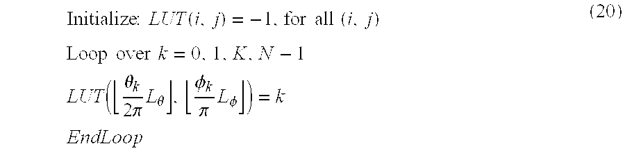
- where └•┘ indicates the floor operation that maps real numbers to integers less than equal to the operand. As the above operation will undoubtedly leave “holes” (cells with “−1”), these holes are filled with the nearest frame number, for instance, via
- Loop over all(i,j) such that LUT(i,j)=−1 (21)
- Find the nearest (i*,j*) such that LUT(i*,j*)≠−1
- LUT(i,j)=LUT(i*,j*)
- EndLoop
- The concept of “nearest” frame number above may be taken to be the one with the smallest l 2-norm:
- ∥(θk,φk)−(θk*,φk*)∥2 2=(θ−θk*)2+(φ−φk*)2 (22)
- where k=LUT(i,j) and k*=LUT(i*,j*) denote the corresponding frame numbers. The operation within the loop above may be performed via repeated use of the morphological operation “dilate”. Note that other metrics or distances may also be used in finding the “nearest” cell.
- Upon receipt of the user inputs, θ and φ, the 3-D viewer simply decompresses and displays the following frame number:

- In vision applications the precision of the angle information (θ and φ) may be important. However, for the 3-D visualization application of the present invention, as long as the images captured are closely spaced, the accuracy of the two angles is not that critical, as the image display is purely for visualization purposes. Thus, displaying the nearest frame, i.e., the frame closest to the current (θ and φ), approximated through Eqn. (23) suffices.
- 2. Display of 3-D Objects by Random Access
- The 3-D viewer is able to display the 3-D image sequence f(k),k=0,1,K,N−1, as the user clicks and drags the mouse across the displayed object. Initially, the user is presented simply with one of the images in the sequence. Upon a user mouse drag, the display is updated with the appropriate image according to a set of rules to provide realistic manipulation of the 3-D object. The manipulation of the displayed object will be based on either of the two modes: NEWS (north-east-west-south) and AVIATION. These two modes behave differently based on the same mouse action.
- FIG. 8A shows the NEWS mode where a left (or right) drag rotates the object along the “west” (or “east”) direction. A down (or up) drag will rotate the object along the “south” (or “north”) direction. FIG. 8B shows the AVIATION mode where a drag along one direction will always correspond to a rotate along that direction. In other words, in the AVIATION mode, the mouse drag direction always corresponds to the direction of the two orthogonal great circles one of which coincides with the current direction of the object. Mathematically, the two operational modes can be summarized as follows.
- Assume the current object direction with respect to the north pole to be ψ, and the user mouse drag of δR and δU. Then, for the NEWS mode the update equations become:
- θnew=θold+δR (24)
- φnew=φold+δU (25)
-

- and for the AVIATION mode:
- θnew=θ(θold,φold,ψold) (27)
- φnew=φ(θold,φold,ψold) (28)
- ψnew=ψ(θold,φold,ψold) (29)
- In the AVIATION mode, there exists several possibilities for updating functions θ(•), φ(•) and ψ(•). In particular, the following north reference system may be applied, typically used in navigation systems.
- θ(θold,φoldψold) =θold+δR cos ψ+δU sin ψ (30)
- φ(θold,φoldψold) =φold−δR sin ψ+δU cos ψ (31)
- ψ(θold,φoldψold) =ψold (32)
- In both cases above, 4, does not change through the mouse motion, the user must manually rotate the image to view at a desired rotation angle. Other possibilities exist as well. In FIG. 7, the lower left pane (3-D view pane) is the ActiveX control which implements the two 3-D object control approaches, NEWS and AVIATION modes.
- To the web surfers only the ActiveX control (3-D view pane) is presented for viewing the 3-D object. In any case, for both modes, the image displayed is ƒ ψ(LUT(└θLθ/(2π)┘,└φLφ/π┘)), where the subscript denote the image (object) rotation by the angle ψ. Thus, the 3-D viewer must support random access as well as rotation. The 3-D viewer also supports other usual functions such as zoom and pan.
- 3. Pre-decode for Fast Display
- As the image sequence is encoded as a video, in order to facilitate real-time manipulation, pre-decode of certain frames must be performed a priori. For example, the MPEG standard encodes the video sequence as a group of pictures (GOP) unit. An instance of a GOP of 12 frames may be IBBPBBPBBPBB, where each character represents frame types. I-frames can be decoded independently; P-frames require decoding of previous anchor frame (I- or P-frame); and B-frames require decoding of two adjacent anchor frames.
- As this particular application requires random access of an arbitrary frame within a GOP, decoding a particular frame within the GOP may require decoding several frames before and after the frame of interest. Of course, for playing the encoded sequence as a normal video, such problems do not exist as all frames are decoded in the natural order. The application of the present invention, however, must support frame decoding not necessarily in sequence.
- For the GOP of IBBPBBPBBPBB, if just I-frames are decoded a priori, it may require up to four decodes for a random access of the last two B-frames. However, if all I- and P-frames are decoded in advance and reside in local memory, then one (or none) decode would be sufficient to display a particular frame within the GOP. This is precisely the approach that has been taken. That is, it has been opted to pre-decode all I- and P-frames into a local buffer, so that at most one (or none) decode is all that is required to view a particular frame. To save memory, the pre-decoded frames are losslessly encoded.
- Another possibility would be to encode the sequence where GOPs are IBBBBBBBBBBB and decode the I-frame a priori. In this case, if all I-frames are decoded within the video, a random access of a particular frame would amount of one (or none) decode.
- Those skilled in the art would appreciate that other compression algorithms such as H.261, H.263, and H.263+ may be used instead of MPEG.
- 4. Multimedia Streaming
- The display software (an ActiveX Control) does not need to wait for all the data to be received before the display and manipulation of the 3-D object. As the data is transferred over the network, the display and manipulation can begin as soon as one or more frames have been received. The implemented software of the present invention first receives and decodes the file header including the number of frames, details of the GOP structure, bit rate, etc. As soon as all necessary information has been decoded, an independent thread (of lower priority) is activated to download the rest of the data. As the thread receives data, it communicates with the main display software as to which frames have or have not been received. As such, the transmission order of the MPEG sequence is altered to transmit all I-frames first, followed by P-, and then B-frames. Even within the same frame type, for instance I-frames, the more important frames are transmitted before the less important ones. As the frames are received, the software pre-decodes I- and P-frames. The received frames are flagged so that the display software is able to use the data as soon as it becomes available.
- In addition to the 3-D data (video), the file also consists of other multimedia streams, such as the zoom data and other video data that can be downloaded at the user request. For instance, if the user wants a detailed (zoomed) view at a certain viewing angle, upon the user request, a download of a separate multimedia stream is initiated. Another instance may be a download of a particular video (an opening of a refrigerator door) upon user request.
- To summarize, most existing 3-D visualization techniques require a two-step process. First, a model of the object is generated and then stored. When the user request a view of the object at a particular view angle, the image must be rendered based on the model before being presented to the user. It is this image rendering process that prohibits the user from manipulating complex and natural objects in real-time. In the approach of the present invention, the model generation as well as the image rendering steps has been eliminated. As such, visualization and manipulation of 3-D objects can be performed in real-time over the network using an ordinary PC as a client.
- C. 3-D Imaging Center
- FIG. 9 shows the process chart of the one-stop service for 3-D content management approach. It includes the 3-
D imaging center 130 equipped with 3-D image capture device, a server, and a connection to theInternet 131. An individual 132 personally visits the 3-D imaging center 130 with the real 3-D object to be imaged (or send the object). Upon imaging the real 3-D object from all possible view angles, be it slice or spiral sampling, the image sequence is stored in to a centralized (or distributed)database 133. The individual leaves the imaging center with a URL of a file containing the 3-D content. - The individual may then publish the URL on his/her web so that
web surfers 134 have access to the 3-D content. Even without publishing the URL at a particular Web page, he/she may still view the 3-D object simply by typing the URL into the Web browser. The URL of the 3-D content may or may not be password protected. Clients of such 3-D imaging center includes both large and small corporations, as well as private individuals with a need to display objects in 3-D over the Internet. The system of the present invention can be used by non-technical individuals as the system has eliminated all technical details that today's user must learn in order to provide such 3-D visualization of real 3-D objects. - The visualization and manipulation of 3-D object has not received the popularity that images and videos have. Perhaps, it is due to the fact that most individuals wishing to display a 3-D object over the Web needs to get over the steep learning curve for including a 3-D object on a home page. The concept of one-stop service for 3-D object management approach in accordance with the present invention will essentially eliminate this steep learning curve for individuals and professionals with 3-D content (objects) to be shown on Web pages.
- D. System Implementation
- FIG. 10 shows a block diagram of the system offering a total service for 3-D visualization over the Internet. The 3-D object is first imaged by the 3-D
Image Capture System 151. The captured 3-D content may then be stored into the 3-D Image Database 153, or it may be edited by the 3-D Image Editor 152. In any case, the 3-D content is eventually stored into the 3-D Image Database 153. The 3-D content may then be published through its assigned URL, which may or may not be password protected. Once published, any web surfer can view the image through the 3-D Image Viewer 154. The software implementation of the first three modules (151, 152 and 153) is relatively straightforward. - FIGS. 11 and 12 show the flowchart of the software that implements the 3-
D Image Viewer 154. The software consists of three main threads: Stream Decode, Data Receive and User Interaction threads. FIG. 11 shows the Stream Decode Thread and FIG. 12 shows the other two threads. - At the start ( 210) of the
Stream Decode thread 201, step (211) initializes various arrays and internal variables. In step (212), it waits for the next frame. Once the frame has been received (Data Receivethread 202 sets an appropriate variable in the RAM 204), the control is moved to step (213). In step (213), if the frame received is the very first frame within the image sequence (3-D content), it outputs the frame onto the user screen. If not, the control is moved to the next step. In step (215), the anchor frames (e.g., I and P frames of MPEG) are pre-decoded and stored (dotted arrow) in the RAM (heap). In step (216), the look-up-table 205 (LUT, previously described) is updated to facilitate fast random access by theUser Interaction Thread 203. In step (217), the thread exits to an end (218) if all frames have been received. If not, the control goes back and waits for the next frame. - The Data Receive
thread 202 after astart 220 initializes various arrays and internal variables in step (221). As the data over the Internet is received in packet units, step (222) captures and stored the received data into the RAM. It also keeps track of the number of frames received for the previous Stream Decode thread. Step (223) checks to see if there are more data to be received. If there are more data to be received, then it loops back to step (222) and if not, the thread exits to anend 224. - The
User Interaction thread 203 initializes, after astart 240, various arrays and internal variables in step (241). As the user of the 3-D Viewer drags the mouse, the mouse action is processed in step (242). The actual mouse drag (δU, δR) is used to compute the current frame number using the LUT. Using the current frame number along with the pre-decoded anchor frame data in the RAM, the current frame is displayed in step (243). The process of receiving mouse event (242) and displaying the frame (243) is repeated until the user quits the 3-D Viewer program. - In summary, it is the User Interaction thread that receives and processes the mouse actions. As such, it is run at the highest priority. The Data Receive thread independently receives the data over the Internet. As more data (frame) is received, the User Interaction thread is able to display more and more frames. The Stream Decode thread simply updates the look-up-table (LUT) and decodes the anchor frames as frames are received to facilitate fast refresh of the user display. Thus, through this design, users can manipulate the 3-D object in real time (20-30 frames per second) and more importantly, users do not have to wait until all data has been received.
- E. Input Means Other than Camera
- The aforementioned visualization technique is not limited to images of real objects captured by a physical camera. One could easily conceive a virtual camera “capturing” images from a 3-D model (e.g., mesh or triangulation) or a 3-D volume data set (e.g., 3-D medical images). The 3-D model within a generic CAD (computed aided design) program could easily be used to generate a sequence of images, each tagged by azimuth and elevation angles θ and φ.
- Similarly, a 3-D volume data set obtained by conventional medical scanners, such as positron emission tomography (PET), single positron emission computed tomography (SPECT), X-ray computed tomography (CT), ultrasound, and magnetic resonance imaging (MRI), may also be used to generate a sequence of 2-D images, each tagged by azimuth and elevation angles θ and φ. The way in which the images are captured would of course depend upon the particular system under consideration.
- Taking the 3-D CT volume data set, for instance, of a human body, the 3-D volume can be projected to generate a set of 2-D images at a set of view angle θ and φ. The projection techniques are well known to those skilled in the art, which include: the maximum intensity projection (MIP), the minimum intensity projection (MinIP), the radiographic projection, the volume rendering and the surface rendering techniques. In these projection techniques, typically, a ray is cast through the 3-D volume data at the angle θ and φ and the resulting pixel value at the 2-D image is: the maximum pixel value (MIP) of all pixels on the ray, the minimum pixel value (MinIP) of all pixels on the ray, the average pixel value (radiographic) of all pixels on the ray, a function of the emittance and luminance (volume rendering) of all pixels on the ray, and finally a function of orientation of the first surface on the ray with respect to one or several virtual light sources (surface rendering).
- Even for the case of generating 2-D images from 3-D models, for instance, using a CAD program, the rendering can be performed for a set of view angles θ and φ.
- Thus, using these approaches, be it using a 3-D volume data (as in medical images) or a CAD program, one can generate a sequence of 2-D images, each tagged with the view angle θ and φ. As such, the previous discussion on 3-D visualization of natural objects is fully applicable to medical data as well as the CAD data, since both approaches are able to generate a sequence of 2-D images with all frames (images) tagged with the view angles θ and φ. Furthermore, the sequence can be compressed, stored and viewed in 3-D at a desired time. For compression, as for real objects, encoding schemes such as MPEG, Motion JPEG, H.261, H.263 and H.263+ may be used.
- While the invention has been described with reference to preferred embodiments, it is not intended to be limited to those embodiments. It will be appreciated by those of ordinary skilled in the art that many modifications can be made to the structure and form of the described embodiments without departing from the spirit and scope of this invention.
Claims (83)
1. A method of visualizing a real 3-D object by a user using a computer, comprising the steps of:
capturing the images of the object as a sequence of images;
encoding the sequence of images as video having video frames; and
viewing the object in 3-D by random access of the video.
2. The method of claim 1 , wherein step of capturing is performed by
taking samples of the images of the object from a viewing angle of an azimuth angle θ and an elevation angle φ in the spherical coordinates.
3. The method of claim 2 , wherein the video frames are tagged with θ and φ).
4. The method of claim 2 , wherein the step of taking samples uses a slicing sampling technique where a series of samples are taken with θ updated in constant steps and with φ fixed before another series of samples are taken with the updated φ.
5. The method of claim 2 , wherein the step of taking samples uses an anisotrophic spiral sampling technique, where a series of samples are taken with θ and φ changed in constant steps.
6. The method of claim 2 , wherein the step of taking samples uses an isotrophic spiral sampling technique, where a series of samples are with θ and φ changed so that the distance between two adjacent samples is substantially equal.
7. The method of claim 1 , wherein the video is streamed so that the viewing can start as soon as one or more frames have been received.
8. The method of claim 1 , wherein the step of encoding includes the step of compressing the video.
9. The method of claim 8 , wherein the step of compressing uses MPEG.
10. The method of claim 8 , wherein the step of compressing uses H.261.
11. The method of claim 8 , wherein the step of compressing uses H.263.
12. The method of claim 8 , wherein the step of compressing uses H.263+.
13. The method of claim 1 , wherein the step of viewing includes the step of pre-decoding the video for real-time display.
14. The method of claim 1 , wherein the video is compressed using MPEG and the step of viewing the object includes the step of streaming I frames followed by P frames followed by B frames.
15. The method of claim 1 , wherein the step of viewing the object includes the step of streaming the most important frames first.
16. The method of claim 1 , further including the step of editing the captured images before encoding.
17. The method of claim 1 , further comprising the step of manipulating the object while viewing the object.
18. The method of claim 17 , wherein the step of manipulating includes the step of rotating the object.
19. The method of claim 17 , wherein the step of manipulating includes the step of zooming the object.
20. The method of claim 17 , wherein the step of manipulating includes the step of manipulating the object in the NEWS (north-east-west-south) mode, where the object is rotated along the east-west direction or along the north-south direction.
21. The method of claim 17 , wherein the step of manipulating includes the step of manipulating the object in the AVIATION mode, where the object is rotated along the direction of the two orthogonal great circle of a sphere having the object at the center.
22. The method of claim 1 , further comprising the step of storing the image sequence in a database.
23. The method of claim 22 , wherein the database is a centralized database.
24. The method of claim 22 , wherein the database is a distributed database.
25. The method of claim 22 , wherein the database is accessed through a network.
26. The method of claim 25 , wherein the network is the Internet.
27. The method of claim 26 , further comprising the step of publishing the URL corresponding to the location of the image sequence within the database.
28. The method of claim 27 , wherein the URL is password protected.
29. The method of claim 1 , wherein the step of viewing including the step of downloading a separate multimedia stream.
30. The method of claim 29 , wherein the separate multimedia steam includes zoom data requested by the user.
31. The method of claim 26 , wherein the separate multimedia stream includes other related data requested by the user.
32. The method of claim 31 , wherein the related data is video.
33. The method of claim 31 , wherein the related data is still images.
34. The method of claim 31 , wherein the related data is sound.
35. The method of claim 31 , wherein the related data is coordinates of points on the object.
36. A system of visualizing a real 3-D object by a user using a computer, comprising the steps of:
an image capture device for capturing images of the object as a sequence of images;
an encoder for encoding the sequence of images as video having video frames; and
a viewer for viewing the object in 3-D.
37. The system of claim 36 , wherein the image capture device includes a camera.
38. The system of claim 36 , wherein the image capture device has means for taking samples of the images of the object from a viewing angle of an azimuth angle θ in the horizontal plane and an elevation angle φ from the horizontal plane.
39. The system of claim 38 , wherein the video frames are tagged with θ and φ.
40. The system of claim 36 , wherein the video is streamed so that the viewing can start as soon as one or more frames have been received.
41. The system of claim 36 , wherein the encoder includes a video compressor for compressing the video.
42. The system of claim 41 , wherein the video compressor is an MPEG encoder.
43. The system of claim 41 , wherein the video compressor is an H.261 encoder.
44. The system of claim 41 , wherein the video compressor is an H.263 encoder.
45. The system of claim 36 , wherein the viewer includes a look-up-table (LUT) for mapping the view angle to a frame number.
46. The system of claim 36 , wherein the viewer includes a pre-decoder for pre-decoding the video for fast retrieval.
47. The system of claim 36 , further including an editor for editing the captured images after encoding.
48. The system of claim 37 , wherein the viewer includes means for manipulating the object while viewing.
49. The system of claim 37 , further comprising a database for the image sequence in a database.
50. The system of claim 49 , wherein the database is a centralized database.
51. The system of claim 49 , wherein the database is a distributed database.
52. The system of claim 49 , further comprising a network for access the database.
53. The system of claim 52 , wherein the network is the Internet.
54. A program product for viewing and manipulating a real 3-D object, which can run at a computer to perform the steps of:
capturing the images of the object as a sequence of images;
encoding the sequence of images as video having video frames;
storing the video in a database;
viewing the object in 3-D through random access of the video; and
manipulating the object in 3-D.
55. The program product of claim 54 , wherein the video is encoded using MPEG.
56. The program product of claim 54 wherein the database is accessed through the Internet.
57. The method for enabling a user to visualize and manipulate a real 3-D object, comprising the steps of:
capturing the images of the object as a sequence of images;
encoding the sequence of images as video having video frames;
storing the video in a database; and
sending the video at the request of the user over a network.
58. The method of claim 57 , wherein the video is encoded using MPEG.
59. The method of claim 57 , wherein the network is the Internet.
60. The method of claim 57 , further comprising the steps of:
receiving the video by a user;
viewing the object in 3-D through random access of the received video; and
manipulating the object in 3-D.
61. A method of visualizing 3-D volume data of an object, comprising the steps of:
capturing the 3D volume data as a stack of 2D tomographic images of the object;
obtaining a sequence of projected 2D images by projecting the 3D volume data at prescribed azimuth and elevation angles;
encoding the sequence of projected 2D images wherein each images are tagged with azimuth and elevation angles;
storing the sequence of 2D images; and
viewing the object in 3-D by random access of stored 2D image sequence.
62. The method of claim 61 wherein the step of capturing the 3D volume data uses positron emission tomography (PET).
63. The method of claim 61 , wherein the step of capturing the 3D volume date uses single positron emission computed tomography (SPECT).
64. The method of claim 61 , wherein the step of capturing the 3D volume data uses X-ray computed tomography (CT).
65. The method of claim 61 , wherein the step of capturing the 3D volume data uses ultrasound imaging.
66. The method of claim 61 , wherein the step of capturing the 3D volume data uses magnetic resonance imaging (MRI),
67. The method of claim 61 wherein the step of encoding includes video encoding using MPEG.
68. The method of claim 61 , wherein the object includes human bodies.
69. The method of claim 61 , wherein the object includes biological tissues.
70. The method of claim 61 , wherein the object includes organic materials.
71. The method of claim 61 , wherein the object includes inorganic materials.
72. The method of claim 61 , further comprising the step of manipulating the object.
73. The method of claim 72 , wherein the step of manipulating includes the step of rotating the object.
74. A method of visualizing 3-D volume data of an object, comprising the steps of:
obtaining a sequence of 2D images at prescribed azimuth and elevation angles rendered by a CAD program;
encoding the sequence of 2D images where each images are tagged with azimuth and elevation angles;
storing the sequence of 2D images; and
viewing the object in 3-D by random access of stored 2D image sequence.
75. The method of claim 74 , wherein the step of encoding includes video encoding using MPEG.
76. The method of claim 74 , further including the step of manipulating the object.
77. The method of claim 76 , wherein the step of manipulating includes the step of rotating the object.
78. A method of providing a customer with a one-stop service for 3-D visualization of a real object over the Internet, comprising the steps of:
receiving the object from the customer;
capturing images of the object as a sequence of images each images tagged with an azimuth angle θ and an elevation angle φ in the spherical coordinates; and
storing the image sequence in a database for transmission over the Internet at the request of a user.
79. The method of claim 78 , wherein the image sequence is assigned a URL for a user of the Internet to access the image sequence.
80. The method of claim 79 , wherein the accessed image sequence is used to view the object in 3-D by the user.
81. The method of claim 79 , wherein the accessed image sequence is used to manipulate the object in 3-D by the user.
82. The method of claim 78 , wherein the image sequence is encoded as video.
83. The method of claim 82 , wherein the video encoding uses MPEG.
Priority Applications (1)
| Application Number | Priority Date | Filing Date | Title |
|---|---|---|---|
| US09/873,056 US6983064B2 (en) | 2001-04-19 | 2001-06-01 | Method and apparatus for visualization and manipulation of real 3-D objects in networked environments |
Applications Claiming Priority (2)
| Application Number | Priority Date | Filing Date | Title |
|---|---|---|---|
| US28504401P | 2001-04-19 | 2001-04-19 | |
| US09/873,056 US6983064B2 (en) | 2001-04-19 | 2001-06-01 | Method and apparatus for visualization and manipulation of real 3-D objects in networked environments |
Publications (2)
| Publication Number | Publication Date |
|---|---|
| US20030031380A1 true US20030031380A1 (en) | 2003-02-13 |
| US6983064B2 US6983064B2 (en) | 2006-01-03 |
Family
ID=23092496
Family Applications (1)
| Application Number | Title | Priority Date | Filing Date |
|---|---|---|---|
| US09/873,056 Expired - Fee Related US6983064B2 (en) | 2001-04-19 | 2001-06-01 | Method and apparatus for visualization and manipulation of real 3-D objects in networked environments |
Country Status (4)
| Country | Link |
|---|---|
| US (1) | US6983064B2 (en) |
| EP (1) | EP1425678A1 (en) |
| KR (1) | KR20020081661A (en) |
| WO (1) | WO2002086752A1 (en) |
Cited By (14)
| Publication number | Priority date | Publication date | Assignee | Title |
|---|---|---|---|---|
| US20050094732A1 (en) * | 2003-10-30 | 2005-05-05 | Debargha Mukherjee | Data communications methods, compressed media data decoding methods, compressed media data decoders, articles of manufacture, and data communications systems |
| US20050249398A1 (en) * | 2004-04-21 | 2005-11-10 | Ali Khamene | Rapid and robust 3D/3D registration technique |
| DE102005036999A1 (en) * | 2005-08-05 | 2007-02-15 | Siemens Ag | Method and arrangement for representing time-varying processes in medical imaging |
| US20070242069A1 (en) * | 2006-04-12 | 2007-10-18 | Kabushiki Kaisha Toshiba | Medical image display apparatus |
| US20090240654A1 (en) * | 2008-03-21 | 2009-09-24 | Limber Mark A | File Access Via Conduit Application |
| US20090237411A1 (en) * | 2008-03-21 | 2009-09-24 | Gossweiler Iii Richard C | Lightweight Three-Dimensional Display |
| US20090293003A1 (en) * | 2004-05-04 | 2009-11-26 | Paul Nykamp | Methods for Interactively Displaying Product Information and for Collaborative Product Design |
| US20100119129A1 (en) * | 2008-11-10 | 2010-05-13 | Fujifilm Corporation | Image processing method, image processing apparatus, and image processing program |
| US20130009957A1 (en) * | 2011-07-08 | 2013-01-10 | Toshiba Medical Systems Corporation | Image processing system, image processing device, image processing method, and medical image diagnostic device |
| US20150281633A1 (en) * | 2014-03-26 | 2015-10-01 | Vivotek Inc. | Method for reverse video playback and computer-readable medium |
| US20160138860A1 (en) * | 2013-10-18 | 2016-05-19 | Lg Electronics Inc. | Refrigerator and control method for the same |
| CN105959702A (en) * | 2016-05-30 | 2016-09-21 | 北京奇艺世纪科技有限公司 | Spherical video coding method and device |
| US9920979B2 (en) | 2013-10-18 | 2018-03-20 | Lg Electronics Inc. | Refrigerator and control method for the same |
| US10275934B1 (en) * | 2017-12-20 | 2019-04-30 | Disney Enterprises, Inc. | Augmented video rendering |
Families Citing this family (13)
| Publication number | Priority date | Publication date | Assignee | Title |
|---|---|---|---|---|
| US8046676B2 (en) * | 2004-03-15 | 2011-10-25 | Autodesk, Inc. | Automatic view creation in a sheet set manager for a graphics program |
| US20050204304A1 (en) * | 2004-03-15 | 2005-09-15 | Autodesk, Inc. | User interface elements of a sheet set manager for a graphics program |
| JP4690683B2 (en) * | 2004-09-13 | 2011-06-01 | 株式会社東芝 | Ultrasonic diagnostic apparatus and medical image browsing method |
| US9508190B2 (en) * | 2006-06-09 | 2016-11-29 | Thomson Licensing | Method and system for color correction using three-dimensional information |
| US7441828B2 (en) * | 2006-06-14 | 2008-10-28 | Kojima Press Industry Co., Ltd. | Pedestrian protection apparatus for vehicle |
| KR101342987B1 (en) * | 2006-11-21 | 2013-12-18 | 톰슨 라이센싱 | Methods and systems for color correction of 3d images |
| US20080252786A1 (en) * | 2007-03-28 | 2008-10-16 | Charles Keith Tilford | Systems and methods for creating displays |
| ES2370037B1 (en) * | 2009-10-09 | 2012-10-22 | Desarrollos De Sistemas Avanzados, S.L | SPHERICAL COORDINATE MANIPULATOR TO GUIDE VISION CAMERAS AND OTHER DEVICES |
| US9294757B1 (en) | 2013-03-15 | 2016-03-22 | Google Inc. | 3-dimensional videos of objects |
| US10033992B1 (en) | 2014-09-09 | 2018-07-24 | Google Llc | Generating a 3D video of an event using crowd sourced data |
| US9917898B2 (en) * | 2015-04-27 | 2018-03-13 | Dental Imaging Technologies Corporation | Hybrid dental imaging system with local area network and cloud |
| US10875246B2 (en) | 2015-05-01 | 2020-12-29 | Jay Lee | System and method for additive manufacturing using spherical coordinates |
| US10122997B1 (en) | 2017-05-03 | 2018-11-06 | Lowe's Companies, Inc. | Automated matrix photo framing using range camera input |
Citations (6)
| Publication number | Priority date | Publication date | Assignee | Title |
|---|---|---|---|---|
| US6012067A (en) * | 1998-03-02 | 2000-01-04 | Sarkar; Shyam Sundar | Method and apparatus for storing and manipulating objects in a plurality of relational data managers on the web |
| US6028907A (en) * | 1998-05-15 | 2000-02-22 | International Business Machines Corporation | System and method for three-dimensional geometric modeling by extracting and merging two-dimensional contours from CT slice data and CT scout data |
| US6477267B1 (en) * | 1995-12-22 | 2002-11-05 | Dynamic Digital Depth Research Pty Ltd. | Image conversion and encoding techniques |
| US6507618B1 (en) * | 2000-04-25 | 2003-01-14 | Hewlett-Packard Company | Compressed video signal including independently coded regions |
| US6513069B1 (en) * | 1996-03-08 | 2003-01-28 | Actv, Inc. | Enhanced video programming system and method for providing a distributed community network |
| US6511426B1 (en) * | 1998-06-02 | 2003-01-28 | Acuson Corporation | Medical diagnostic ultrasound system and method for versatile processing |
Family Cites Families (4)
| Publication number | Priority date | Publication date | Assignee | Title |
|---|---|---|---|---|
| US5959631A (en) * | 1996-08-28 | 1999-09-28 | Hewlett-Packard Company | Hardware and software for the visualization of three-dimensional data sets |
| US5946645A (en) * | 1997-04-09 | 1999-08-31 | National Research Council Of Canada | Three dimensional imaging method and device |
| US6147692A (en) * | 1997-06-25 | 2000-11-14 | Haptek, Inc. | Method and apparatus for controlling transformation of two and three-dimensional images |
| US6115052A (en) * | 1998-02-12 | 2000-09-05 | Mitsubishi Electric Information Technology Center America, Inc. (Ita) | System for reconstructing the 3-dimensional motions of a human figure from a monocularly-viewed image sequence |
-
2001
- 2001-05-18 KR KR1020010027296A patent/KR20020081661A/en not_active Application Discontinuation
- 2001-06-01 US US09/873,056 patent/US6983064B2/en not_active Expired - Fee Related
- 2001-06-08 EP EP01937029A patent/EP1425678A1/en not_active Withdrawn
- 2001-06-08 WO PCT/KR2001/000976 patent/WO2002086752A1/en not_active Application Discontinuation
Patent Citations (6)
| Publication number | Priority date | Publication date | Assignee | Title |
|---|---|---|---|---|
| US6477267B1 (en) * | 1995-12-22 | 2002-11-05 | Dynamic Digital Depth Research Pty Ltd. | Image conversion and encoding techniques |
| US6513069B1 (en) * | 1996-03-08 | 2003-01-28 | Actv, Inc. | Enhanced video programming system and method for providing a distributed community network |
| US6012067A (en) * | 1998-03-02 | 2000-01-04 | Sarkar; Shyam Sundar | Method and apparatus for storing and manipulating objects in a plurality of relational data managers on the web |
| US6028907A (en) * | 1998-05-15 | 2000-02-22 | International Business Machines Corporation | System and method for three-dimensional geometric modeling by extracting and merging two-dimensional contours from CT slice data and CT scout data |
| US6511426B1 (en) * | 1998-06-02 | 2003-01-28 | Acuson Corporation | Medical diagnostic ultrasound system and method for versatile processing |
| US6507618B1 (en) * | 2000-04-25 | 2003-01-14 | Hewlett-Packard Company | Compressed video signal including independently coded regions |
Cited By (29)
| Publication number | Priority date | Publication date | Assignee | Title |
|---|---|---|---|---|
| US20050094732A1 (en) * | 2003-10-30 | 2005-05-05 | Debargha Mukherjee | Data communications methods, compressed media data decoding methods, compressed media data decoders, articles of manufacture, and data communications systems |
| US20050249398A1 (en) * | 2004-04-21 | 2005-11-10 | Ali Khamene | Rapid and robust 3D/3D registration technique |
| US7724943B2 (en) * | 2004-04-21 | 2010-05-25 | Siemens Medical Solutions Usa, Inc. | Rapid and robust 3D/3D registration technique |
| US20100205533A1 (en) * | 2004-05-04 | 2010-08-12 | Paul Nykamp | Methods for interactive and synchronous display session |
| US8311894B2 (en) | 2004-05-04 | 2012-11-13 | Reliable Tack Acquisitions Llc | Method and apparatus for interactive and synchronous display session |
| US8069087B2 (en) | 2004-05-04 | 2011-11-29 | Paul Nykamp | Methods for interactive and synchronous display session |
| US20090293003A1 (en) * | 2004-05-04 | 2009-11-26 | Paul Nykamp | Methods for Interactively Displaying Product Information and for Collaborative Product Design |
| US7908178B2 (en) | 2004-05-04 | 2011-03-15 | Paul Nykamp | Methods for interactive and synchronous displaying session |
| US20100191808A1 (en) * | 2004-05-04 | 2010-07-29 | Paul Nykamp | Methods for interactive and synchronous display session |
| DE102005036999A1 (en) * | 2005-08-05 | 2007-02-15 | Siemens Ag | Method and arrangement for representing time-varying processes in medical imaging |
| US9019301B2 (en) * | 2006-04-12 | 2015-04-28 | Kabushiki Kaisha Toshiba | Medical image display apparatus in which specification of a medical image enables execution of image processing |
| US20070242069A1 (en) * | 2006-04-12 | 2007-10-18 | Kabushiki Kaisha Toshiba | Medical image display apparatus |
| US8614706B2 (en) | 2008-03-21 | 2013-12-24 | Trimble Navigation Limited | Lightweight three-dimensional display |
| US8125481B2 (en) * | 2008-03-21 | 2012-02-28 | Google Inc. | Lightweight three-dimensional display |
| US8886669B2 (en) | 2008-03-21 | 2014-11-11 | Trimble Navigation Limited | File access via conduit application |
| US8350848B2 (en) | 2008-03-21 | 2013-01-08 | Trimble Navigation Limited | Lightweight three-dimensional display |
| US20090237411A1 (en) * | 2008-03-21 | 2009-09-24 | Gossweiler Iii Richard C | Lightweight Three-Dimensional Display |
| US8355024B2 (en) | 2008-03-21 | 2013-01-15 | Trimble Navigation Limited | Lightweight three-dimensional display |
| US8384713B2 (en) | 2008-03-21 | 2013-02-26 | Trimble Navigation Limited | Lightweight three-dimensional display |
| US20090240654A1 (en) * | 2008-03-21 | 2009-09-24 | Limber Mark A | File Access Via Conduit Application |
| US20100119129A1 (en) * | 2008-11-10 | 2010-05-13 | Fujifilm Corporation | Image processing method, image processing apparatus, and image processing program |
| US20130009957A1 (en) * | 2011-07-08 | 2013-01-10 | Toshiba Medical Systems Corporation | Image processing system, image processing device, image processing method, and medical image diagnostic device |
| US20160138860A1 (en) * | 2013-10-18 | 2016-05-19 | Lg Electronics Inc. | Refrigerator and control method for the same |
| US9920979B2 (en) | 2013-10-18 | 2018-03-20 | Lg Electronics Inc. | Refrigerator and control method for the same |
| US10365034B2 (en) * | 2013-10-18 | 2019-07-30 | Lg Electronics Inc. | Refrigerator and control method for the same |
| US20150281633A1 (en) * | 2014-03-26 | 2015-10-01 | Vivotek Inc. | Method for reverse video playback and computer-readable medium |
| US9462219B2 (en) * | 2014-03-26 | 2016-10-04 | Vivotek Inc. | Method for reverse video playback and computer-readable medium |
| CN105959702A (en) * | 2016-05-30 | 2016-09-21 | 北京奇艺世纪科技有限公司 | Spherical video coding method and device |
| US10275934B1 (en) * | 2017-12-20 | 2019-04-30 | Disney Enterprises, Inc. | Augmented video rendering |
Also Published As
| Publication number | Publication date |
|---|---|
| EP1425678A1 (en) | 2004-06-09 |
| KR20020081661A (en) | 2002-10-30 |
| WO2002086752A1 (en) | 2002-10-31 |
| US6983064B2 (en) | 2006-01-03 |
Similar Documents
| Publication | Publication Date | Title |
|---|---|---|
| US6983064B2 (en) | Method and apparatus for visualization and manipulation of real 3-D objects in networked environments | |
| US6633317B2 (en) | Image-based walkthrough system and process employing spatial video streaming | |
| US6192393B1 (en) | Method and system for panorama viewing | |
| EP0919956B1 (en) | Image display | |
| US7206804B1 (en) | Methods and systems for transmitting digital images | |
| US8074241B2 (en) | Process for displaying and navigating panoramic video, and method and user interface for streaming panoramic video and images between a server and browser-based client application | |
| US7065530B2 (en) | Data structure for efficient access to variable-size data objects | |
| US9087372B2 (en) | Automated fly through review mechanism | |
| WO2017062865A1 (en) | Systems, methods and software programs for 360° video distribution platforms | |
| US20100054578A1 (en) | Method and apparatus for interactive visualization and distribution of very large image data sets | |
| US20230326109A1 (en) | System For Transmitting And Viewing A Series Of Images | |
| EP2669830A1 (en) | Preparation and display of derived series of medical images | |
| CA2566638A1 (en) | Method and system for remote and adaptive visualization of graphical image data | |
| Zhu et al. | Towards peer-assisted rendering in networked virtual environments | |
| US20080043015A1 (en) | Online volume rendering system and method | |
| Brivio et al. | PhotoCloud: Interactive remote exploration of joint 2D and 3D datasets | |
| US6628282B1 (en) | Stateless remote environment navigation | |
| Chen et al. | Interactive, internet delivery of visualization via structured prerendered multiresolution imagery | |
| KR20040049832A (en) | Method and Apparatus for Visualization and Manipulation of Real 3-D Objects in Networked Environments | |
| Lei et al. | Image-based walkthrough over internet on mobile devices | |
| Li et al. | Image-based Walkthrough over the Internet | |
| Hu et al. | Use image streaming technologies to present high resolution images on the internet | |
| Yoon et al. | Image-assisted visualizations over networks | |
| Ekpar et al. | On the Interactive Visualization of Very Large Image Data Sets | |
| Yoon et al. | Web-based virtual tour using the Tour Into the Picture (TIP) technique |
Legal Events
| Date | Code | Title | Description |
|---|---|---|---|
| AS | Assignment |
Owner name: OPENVISUAL INC., KOREA, REPUBLIC OF Free format text: ASSIGNMENT OF ASSIGNORS INTEREST;ASSIGNOR:SONG, SAMUEL MOON-HO;REEL/FRAME:011885/0318 Effective date: 20010620 |
|
| REMI | Maintenance fee reminder mailed | ||
| LAPS | Lapse for failure to pay maintenance fees | ||
| STCH | Information on status: patent discontinuation |
Free format text: PATENT EXPIRED DUE TO NONPAYMENT OF MAINTENANCE FEES UNDER 37 CFR 1.362 |
|
| FP | Expired due to failure to pay maintenance fee |
Effective date: 20100103 |