US20030033893A1 - Cement expansion/contraction test apparatus - Google Patents
Cement expansion/contraction test apparatus Download PDFInfo
- Publication number
- US20030033893A1 US20030033893A1 US10/177,742 US17774202A US2003033893A1 US 20030033893 A1 US20030033893 A1 US 20030033893A1 US 17774202 A US17774202 A US 17774202A US 2003033893 A1 US2003033893 A1 US 2003033893A1
- Authority
- US
- United States
- Prior art keywords
- section
- cement
- mold
- base
- pressure
- Prior art date
- Legal status (The legal status is an assumption and is not a legal conclusion. Google has not performed a legal analysis and makes no representation as to the accuracy of the status listed.)
- Granted
Links
Images


Classifications
-
- G—PHYSICS
- G01—MEASURING; TESTING
- G01N—INVESTIGATING OR ANALYSING MATERIALS BY DETERMINING THEIR CHEMICAL OR PHYSICAL PROPERTIES
- G01N33/00—Investigating or analysing materials by specific methods not covered by groups G01N1/00 - G01N31/00
- G01N33/38—Concrete; ceramics; glass; bricks
- G01N33/383—Concrete, cement
Definitions
- the invention relates to an apparatus and method for use in the measurement of fluids used in the field of oil and gas recovery. More particularly, this invention relates to an apparatus such as a mold adapted to detect the expansion or shrinkage of cement as the cement is exposed to simulated down-hole conditions, such as high-pressure, high-temperature applications. A method for measuring the expansion or shrinkage of the cement is also disclosed.
- the migration of well fluids will result in lower production revenue. Additionally, the migration of well fluids can increase well maintenance costs, increase casing corrosion, and reduce the life of the well. The formation of micro-annuli may require a secondary cement job or squeeze cementing, thus increasing the total well cost. The migration of well fluids can also lead to complete loss of the well due to blowout. In injection wells, the poor cement bonding can lead to a higher injection cost and lower well efficiency. These well fluids can migrate, contaminate, and pollute fresh water aquifers.
- the volumetric property of the slurry is measured directly by the volume of mineral oil injected. Therefore, it is necessary to calibrate the pump and establish the relationship between the volume of oil injected to the positive-displacement pump read-out.
- the pressure regulator will activate the pump by removing or adding mineral oil to the system. These can indicate a false reading of cement volumetric changes. Therefore, it is necessary to establish a mineral oil thermal expansion coefficient for each test temperature.
- the mineral oil correction factor will be used in slurry volumetric calculations.
- the apparatus consists of a test cell, a gear mechanism, a floating piston, potentiometer, autoclave and chart recorder.
- the test cell is divided into three-sections: 1) a water reservoir; 2) a sample chamber; and 3) a measuring head.
- a sintered metal disk and a filter paper are mounted at the bottom of the cement sample. Below the metal disk is a cavity filled with water.
- a metal plug with sealed assembly is used to cap the bottom of the water chamber.
- the autoclave curing pressure is transmitted to the cement during the test by the way of the metal plug to the water and to the cement. This will allow the cement to absorb additional water as required during the hydration process.
- On the top of the cement sample is a rubber cup sleeve that seals the cement against the pressurizing fluid (mineral oil).
- a floating piston is installed on top of the rubber cup sleeve.
- the axial motion of the piston caused by the changes in the matrix volume is converted to a rotational motion by a gear mechanism.
- the gear mechanism will alter the position of the pointer across the potentiometer resistor.
- the shifting position of the pointer across the resistor provides a variation of the voltage signal.
- the measured voltages along with the autoclave-temperature and pressure are monitored continuously by means of a chart recorder.
- the matrix volume change is calculated using the calibration chart.
- the calibration chart is expressed as piston height versus voltage signal reading.
- One advantage of the Ghofrani/Plack apparatus is that fresh water is pushed into the cement matrix while curing.
- the test data from the apparatus can be subjective due to the measuring head design.
- the rubber cup sleeve that seals the cement against the mineral oil can absorb some of the displacement movement or it can swell to provide a positive movement for the piston.
- the mechanical tolerances on the gear mechanism can affect equipment performance from one unit to the other.
- the volumetric change in some slurries may be in the micro-inches spectrum and converting it to axial motion by the piston, to a rotational movement by the gear mechanism, and to electrical signal by the potentiometer.
- the measuring head design may be impractical for field application accuracy may be sacrifice. Currently, none of these concepts has been built commercially to support the oil well industry.
- An apparatus for measuring volumetric changes in cement as the cement is exposed to a given pressure and temperature in a high-pressure high-temperature chamber.
- the apparatus has a first section adjacent a base and a second a second section movably attached to the first section, the second section adjacent the base.
- the first section, the second section, and the base may define a mold into which a measurable amount of cement may be placed.
- the apparatus may include a sensor that is functionally associated with at least one of the sections.
- the sensor may be adapted to measure the movement of the first and second sections relative to one another in response to volumetric changes in the cement when the cement is exposed to simulated down-hole pressures and temperatures.
- the apparatus may include a seal between the first and second sections, in some embodiments.
- the apparatus includes a fastening assembly, which may comprise a first bolt surrounded by a first spring and having a threaded end, the first bolt passing through a first hole in the second section and threadedly engaged with a first threaded hole in the first section, and a second bolt surrounded by a second spring and having a threaded end, the second bolt passing through a second hole in the second section and threadedly engaged with a second threaded hole in the first section, the springs adapted to bias the second section into contact with the first section.
- a fastening assembly which may comprise a first bolt surrounded by a first spring and having a threaded end, the first bolt passing through a first hole in the second section and threadedly engaged with a first threaded hole in the first section, and a second bolt surrounded by a second spring and having a threaded end, the second bolt passing through a second hole in the second section and threadedly engaged with a second threaded hole in the first section, the springs
- an apparatus having a means for moving with volumetric changes in the cement movably attached to the first section, the means for moving adjacent the base.
- the apparatus may include a sensing means contacting at least one of the sections for measuring the movement of the means for moving in response to volumetric changes in the cement when the cement is exposed to high pressure and high temperature, or a means for sealing.
- a basket which may facilitate the processing of multiple molds at the same time.
- the basket may include mounting rods, a top plate, and a bottom plate.
- FIG. 1 shows a top view of one embodiment of the present invention having a mold mounted inside a high-pressure high-temperature chamber.
- FIG. 2 shows a top view of an exploded view of a mold of one embodiment of the present invention.
- FIG. 3 shows an exploded side view of one embodiment of the present invention having anchor blocks.
- FIG. 4 shows a side view of one embodiment of the present invention having a basket.
- a modified high-temperature (HPHT) cement curing chamber 90 is described.
- the HPHT curing chamber 90 consists of autoclave test cell with heaters, temperature controller, and hydraulic pump with pressure regulator. Thus, the HPHT curing chamber may simulate down hole pressures and temperatures.
- the expansion/contraction mold 50 is fitted inside the HPHT curing chamber 90 .
- a high-pressure spring loaded linear displacement transducer 80 (LDT) with Autoclave fittings.
- LDT 80 high-pressure spring loaded linear displacement transducer 80
- the signal from LDT 80 is processed by the Data Acquisition Unit 82 (DAU) and then the DAU 82 communicates the process signal to a device 84 such as computer or a chart recorder.
- the computer or the chart recorder will store the data from the test.
- the equipment will continuously monitor cement expansion, before and after cement hydration process.
- the equipment will also measure cement shrinkage continuously after the cement has set. Measurements may be taken under a humid environment and under down-hole temperature and pressure.
- the innovative mold design will allow cement movement or volumetric changes in all three directions (“X”, “Y”, and “Z” axis). See FIGS. 1, 2, and 3 .
- the HPHT curing chamber 90 can be fitted to accommodate three molds 50 stacked one on top of the other.
- the computer can simultaneously process and store test data from three different cement formulations 10 including test temperature and pressure.
- the number of cement formulations 10 and molds 50 is not limited to three; rather, any number of cement formulations 10 could processed in molds 50 by modifying the size and shape of the chamber 90 or molds 50 , for example.
- the sample of cement is not subject to mechanical restriction on the sample, as the mold design allows the cement 10 to expand or shrink in three axes.
- three different slurry formulations 10 can be tested simultaneously at the same bottom-hole temperature and pressure.
- the apparatus can independently measure the linear expansion or contraction of the three different cement formulations 10 .
- the (HPHT) linear displacement transducer 80 can easily be calibrated with a micrometer. The cement volumetric change is transmitted from the mold body 50 , to the LDT 80 , and to the computer. A calibrated (HPHT) linear displacement transducer 80 will provide a direct reading of expansion or contraction. There is no need for elaborate mathematical calculations. Confining pressure and temperature will not affect the performance of the LDT 80 .
- the cement 10 is cured under a humid environment and under down-hole temperature and pressure.
- Existing HPHT curing chambers 90 can be modified and fitted for the expansion or contraction testing. At the end of the volumetric test, the set cement 10 can be tested for permeability.
- the modified HPHT curing chamber 90 can still be used for compressive strength testing. No need exists for a different machine or pressurized curing vessel. Further, off-the-shelf software can be used to monitor the test. No need exists to invest on different software. An old 468 computer or higher with Windows 95 can be used to monitor and store the test data.
- a standard cement curing chamber 90 may be modified to accept a high-pressure/high temperature linear distance transducer 80 as disclosed herein.
- an expansion/shrinkage mold 50 is fabricated along with the necessary fittings and accessories.
- An electronic circuit may be assembled to measure, collect, and store the test data in a PC computer.
- Test data generated from some embodiments can continuously measure cement expansion or shrinkage accurately under humid conditions and at down-hole temperature and pressure.
- the design of the mold 50 allows the cement 10 to move freely in three (X, Y and Z) axes while curing at down-hole conditions.
- the cement slurry 10 is assumed to expand or shrink uniformly in three axes as long as the slurry is subjected to the same confining conditions.
- the linear distance transducer 80 will detect any movement directly from two parallel planes inside the mold 50 along the X-axis. Alternatively, three linear distance transducers 80 may be utilized to measure movement in the X, Y, and Z directions.
- the linear distance transducer in conjunction with the electronic data acquisition unit is calibrated accurately using a Venier caliper. Once the calibration of the linear displacement transducer is established, re-calibration is not necessary on the preceding test.
- Another feature of the invention is the apparatus does not require any complicated calculations to function.
- the cement slurry 10 , mold 50 , confining fluids 12 , and test cell 90 are exposed to the same test conditions at the same time. Therefore, the coefficient of expansion of the mold 50 , confining fluid 12 , and test cell 90 does not interfere with the test data.
- the slurry 10 is cured under humid condition at down-hole temperature and pressure at all time during the test.
- the cement 10 may continuously change its dimensions several days or more than a week after it has been mixed.
- a curing chamber 90 is used that will accommodate multiple linear distance transducers 80 at the same time.
- High-pressure high-temperature curing chamber 90 is any standard high-pressure high-temperature test cells commercially available, such as Chandler Engineering Curing Vessel model #7-700-5, from Chandler Engineering, Tulsa, Okla. This chamber 90 thus can simulate elevated down-hole pressures and temperatures.
- Mold 50 is shown to be comprised of a first section 60 and a second section 70 as described more fully hereinafter. Mold 50 may be filled with cement 10 .
- Sensor 80 may be a linear displacement transducer. Sensor 80 may contact second section 70 , for example.
- a standard high-pressure high-temperature curing chamber 90 typically is not equipped with a sensor 80 , but can be modified to insert sensor 80 .
- Sensor 80 may be a spring-loaded linear displacement transducer or any other type of linear displacement transducer known by one of ordinary skill in the art having the benefit of this disclosure, such as an electromagnetic linear displacement transducer. Electrically connected to the linear displacement transducer is a data acquisition unit 82 which collects readings from sensor 80 .
- a device 84 Electrically connected to data acquisition unit 82 is a device 84 for storing and displaying the data from the data acquisition unit 82 over time.
- device 84 may be a computer or a chart recorder.
- mold 50 is shown in mold basket 40 described more fully herein.
- the mold 50 includes mounting holes 41 for attaching the molds 50 to a basket 40 as more fully described herein.
- the mold basket 40 is placed into the high-pressure high-temperature chamber 90 .
- a pressurizing medium 12 is then pumped into the chamber to increase the pressure.
- This pressurizing medium may be water, or oil, or any other fluid capable of increasing the pressure within chamber 90 by being pumped into the chamber 90 , by a hydraulic pump (not shown) for example.
- the chamber 90 also includes heaters (not shown) for increasing the temperature within the chamber.
- a seal 52 is placed between the two sections 60 and 70 to prevent the first section 60 and the second section 70 from contacting each other.
- Seal 52 may be an O-ring, or a low-durometer rubber seal, a thin wall tygon tubing, or any other type of seal will allow the sections to be compressed together, as described more fully herein, while preventing the cement from leaking out of the sections.
- first section 60 may be comprised of sides 62 and 64 , each of which is substantially straight and form a plane. Sides 62 and 64 meet at an angle 66 . In this embodiment, angle 66 is 90 degrees. Further, each of sides 62 and 64 has a mating surface 68 and 69 respectively to mate with the second section 70 as described more fully herein.
- second section 70 may be comprised of sides 72 and 74 , each of which is substantially straight and form a plane. Sides 72 and 74 meet at an angle 76 . In this embodiment, angle 76 is 90 degrees. Also shown in FIG. 2 is contact location 77 of the second section 70 . Further, each of sides 72 and 74 has a mating surface 78 and 79 respectively to mate with the first section 60 as described more fully herein.
- second section 70 is movably attached to the first section 60 by a fastening assembly.
- the fastening assembly in this embodiment is comprised as follows. A first bolt 20 having a threaded end is surrounded by a spring 24 . The first bolt 20 passes through a hole 71 in mating surface 78 of the second section 70 . The threaded end of the first bolt 20 is screwed into the threaded hole 61 in mating surface 68 of the first section 60 . In this way, spring 24 biases the second section 70 toward the first section 60 at mating surfaces 78 and 68 , respectively. As described above, first section 60 and second section 70 are separated by seal 52 .
- a first washer 22 also may be utilized around bolt 20 .
- a first alignment pin 26 may also be used to ensure that the second section moves in a linear fashion as described herein and prevents the shearing of first bolt 20 .
- First alignment pin 26 is pressed into a hole (shown in FIG. 2 but not numbered) in mating surface 68 and engages a second hole (shown in FIG. 2 but not numbered) in mating section 78 of second section 70 .
- the fastening assembly also includes a second bolt 30 having a threaded end.
- the second bolt 30 is surrounded by a spring 34 .
- the second bolt 30 passes through a hole 73 in mating surface 79 of the second section 70 .
- the threaded end of the first bolt 20 is screwed into the threaded hole 63 in mating surface 69 of the first section 60 .
- spring 34 biases the second section 70 toward the first section 60 at mating surfaces 79 and 69 , respectively.
- the first and section sections are separated by seal 52 .
- a second washer 32 also may be utilized around bolt 30 .
- a second alignment pin 36 may also be used to ensure that the second section 70 moves in a linear fashion as described herein and prevents the shearing of second bolt 30 .
- Second alignment pin 36 is pressed into a hole (shown in FIG. 2 but not numbered) in mating surface 69 and engages a second hole (shown in FIG. 2 but not numbered) in mating section 79 of second section 70 .
- any type of fastening assembly which movably attaches first section 60 and second section 70 that is known to one of ordinary skill in the art having the benefit of this disclosure would also be acceptable.
- FIG. 3 an exploded side view of one embodiment of the present invention is shown.
- the first section is fixedly attached to the base 54 via bolt 11 .
- the second section 70 is movably attached to the first section 60 via the fastening assembly described above.
- the second section 70 thus rests on the base 54 and may move relative to the base in a horizontal direction, unlike the first section 60 which is fixedly attached to base 54 .
- the mold 50 may include a first anchor block 14 and a second anchor block 15 .
- First and second anchor blocks 14 and 15 may be inserted into channels 18 and 19 of first and section sections 60 and 70 , respectively.
- the anchor blocks 14 and 15 have a triangular cross-section.
- Each anchor block 14 and 15 also includes an anchor bolt 16 and 17 respectively, to which the cement 10 may adhere, as described more fully herein.
- Channels 18 and 19 secure anchor blocks 14 and 15 to preclude movement in an X or Y horizontal direction. However, channels 18 and 19 allow anchor blocks 14 and 15 to move vertically as necessary for proper operation of the mold.
- a single mold 50 may be placed into the high-pressure high-temperature chamber. However, it is often desirable to have multiple cement samples in multiple molds processed under the same temperature and pressure conditions. Therefore, multiple molds 50 may be placed in a mold basket 40 as more fully described herein with respect to FIG. 4. As shown in FIGS. 1, 2, and 3 , molds 50 may include at least one mounting hole for attaching the mold 50 to the basket. The mounting holes 41 may be in the mold lid 94 and in base 54 .
- the mold 50 may have a lid 94 to cover the mold 50 , once filled with cement 10 , to prevent spillage thereof.
- another sensor 80 such as a linear displacement transducer, may contact the lid 94 to measure the expansion or shrinkage of the concrete in the Z-direction, as the anchor blocks move relative to the mold 50 .
- a seal 52 may be placed between the lid and the first and sections 60 and 70 . Seal 52 may be an O-ring, low durometer rubber seal, or tygon tubing, for example.
- lid 94 may be movably attached to the first and second sections 60 and 70 by a fastening assembly, identical that movably attaching the first and second sections. I.e., the fastening assembly may comprise a bolt surrounded by a spring, which passes through a hole in the lid, to threadedly engage in the first and second sections.
- the senor 80 is calibrated. If sensor 80 is a linear displacement transducer, the linear distance transducer 80 in conjunction with the data acquisition unit 82 is calibrated using a Vernier caliper.
- a mold 50 is constructed as described above.
- the cement 10 to be tested is mixed and placed in mold 50 .
- Mold 50 is then inserted into the high-pressure high-temperature chamber 90 solely, or in basket 40 stacked along with other molds 50 .
- the senor may be functionally associated with the mold 50 .
- the sensor may be brought into contact with the contact location 77 of the movable second section 70 of the mold 50 .
- the sensor 80 is in constant contact with the contact location 78 , whether the cement shrinks or expands, by virtue of either a spring or electromagnetic forces of the linear displacement transducer, when used.
- the high-temperature high-pressure chamber 90 is then activated to bring the contents therein to a given operating temperature and pressure simulating downhole conditions. Once the cement 10 sets, the cement 10 attaches to anchor bolts 16 and 17 , when used.
- volumetric changes of the cement 10 is then monitored as follows. First section 60 is fixed to the mold base 54 and therefore does not move. If the cement 10 expands, second section 70 of mold 50 moves toward sensor 80 , as the force of the current expanding overcomes the force of springs 24 and 34 of the fastening assembly. The second section 70 moves linearly toward sensor 80 , due in part to alignment pins 26 and 36 , which are parallel to the axis of sensor 80 . As second section 70 moves toward sensor 80 , sensor 80 sends data to the data acquisition unit 82 , which also stores the temperature and pressure settings of the chamber 90 . Device 84 then stores the data from the acquisition unit 82 with respect to time and may display the results, if desired.
- the expansion of the cement 10 also forces anchor blocks 14 and 15 to move upwardly in channels 18 and 19 in the mold 50 , as the cement 10 is attached to anchor bolts 16 and 17 once set.
- the cement 10 does not expand, but shrinks. If the cement 10 shrinks, movable second section 70 of mold 50 moves away from sensor 80 , as the force of the cement shrinking overcomes seal 52 . Once set, the cement 10 attaches to the anchor blocks 14 and 15 . As the cement 10 shrinks, the second section 70 moves toward first section 60 and away from sensor 80 . Thus, the first and second sections 60 and 70 apply a compressive force to seal 52 . As the seal 52 is comprised of a resilient material such as rubber, the seal compresses.
- the sensor 80 maintains contact with the second section 70 , as the sensor 80 has a biasing means, such as a spring or an electromagnetic field, to ensure constant contact.
- the second section 70 moves linearly toward sensor 80 , due in part to alignment pins 26 and 36 , which are parallel to the axis of sensor 80 .
- sensor 80 sends data to the data acquisition unit 82 , which also stores the temperature and pressure settings of the chamber 90 .
- Device 84 then stores the data from the acquisition unit 82 with respect to time an may display the results, if desired.
- sensor 80 sends data to the data acquisition unit 82 , which also stores the temperature and pressure settings of the chamber 90 .
- Device 84 then stores the data from the acquisition unit 82 with respect to the an may display the results, if desired.
- FIG. 4 a side view of multiple (e.g. three) molds 50 placed in a basket 40 is shown.
- basket 40 includes a bottom plate 46 .
- four mounting rods 42 are connected to the bottom plate 46 .
- Bottom plate has mounting holes through which the mounting rods 42 may be inserted.
- top plate 44 Connected to the opposite end of the mounting rods 42 is top plate 44 . Both bottom plate 46 and top plate 44 are held in place in this embodiment by being threadedly locked to mounting nuts 49 .
- a removable handle 48 is attached to the top plate 44 to facilitate the operator's handling of the basket 40 .
- molds 50 may be placed between the top plate 44 and the bottom plate 46 .
- a first mold 50 a rests on bottom plate 46 a .
- mold 50 a may include mounting holes 41 within the lid 94 a and the base 54 a through which mounting rods 49 are inserted.
- a second mold 50 b may then be stacked above the first mold 50 a .
- second mold 50 b includes a plurality of mounting holes in lid 94 b and base 54 b to accommodate the plurality of mounting rods 42 .
- Base 54 b of this second mold 50 b is connected to the mounting rods 42 at a location such that the base 54 b of the second mold 50 b does not contact the lid 94 a of the first mold 50 a .
- gap 43 a is present between the first mold 50 a and second mold 50 a . This is accomplished by attaching flanges 45 to the mounting rods 42 at a location above the first mold 50 a such that a gap 43 a is created.
- the second mold 50 b is functionally associated with the mounting rods 42 via flanges 45 . This gap allows the cement 10 in the first mold 50 a to expand in the vertical direction, if needed.
- a third mold 50 c may then be stacked above the second mold 50 b .
- Flanges 45 may be connected to the mounting rods 42 above the second mold 50 b .
- the second mold 50 b may be connected to the mounting rods 42 by flanges 45 such that a gap 43 b exists between the second mold 50 b and the third mold 50 c . This gap allows the cement 10 in the second mold 50 b to expand in the vertical direction, if needed.
- top plate 44 of the basket 40 may be connected to the mounting rods 42 such that gap 43 c exists to allow cement in the third mold 50 c to expand in the vertical direction, if needed.
- Top plate 44 of basket 40 may include mounting holes to accommodate the mounting rods 42 .
- Gap 43 c may be created by any number of ways, such as those known to one of ordinary skill in the art having the benefit of this disclosure. For example, flanges 45 as described above could be utilized. Alternatively, the diameter of rods 49 may be reduced at a above lid 94 c such that gap 43 c is created. If the mounting holes in the top plate 44 are smaller than the mounting holes 41 in the mold lid 94 c , the gap 43 c will be created.
- three linear displacement transducers 80 may be connected to the molds 50 , one sensor per mold, to take measurements of three molds simultaneously.
- the device such as a computer can simultaneously process and store test data from three different cement formulations including test temperature and pressure.
- Chart #1 and Chart #2 demonstrate the results of expansion and contraction tests performed using the apparatus of the present invention.
- Chart #1 provides expansion test data for a sample of API Class “A” Cement, which is widely known and used in the oil and gas well service industry. The cement was mixed at 15.6 PPG (pounds per gallon). An expanding cement additive available from BJ Services Company under the name EC-1 was added to the cement preparation to provide early expansion of the set cement. The EC-1 was added at an amount of 10% by weight of the cement. Linear expansion and slurry temperature data are reported.
- Chart #2 provides contraction test data for API Class “A” Cement mixed at 12.5 PPG. Sodium metasilicate, an extender used to produce an economical, low density slurry was added to the cement at an amount of 2% by weight. Calcium chloride, a cement accelerator, was added at an amount of 1% by weight. Slurry temperature and percent linear contraction results were reported.
- Charts 3, 4, 5, and 6 provide the results of additional expansion and contraction tests conducted using the invention disclosed herein.
- Chart 3 provides expansion data for a cement slurry available from BJ Services Company under the name Liquid Stone®.
- An expanding cement additive available from BJ Services Company under the name EC-2 was added to the Liquid Stone® preparation at 7.5% by weight of the slurry.
- the test to measure linear expansion, test pressure and test temperature was conducted at 248° F.
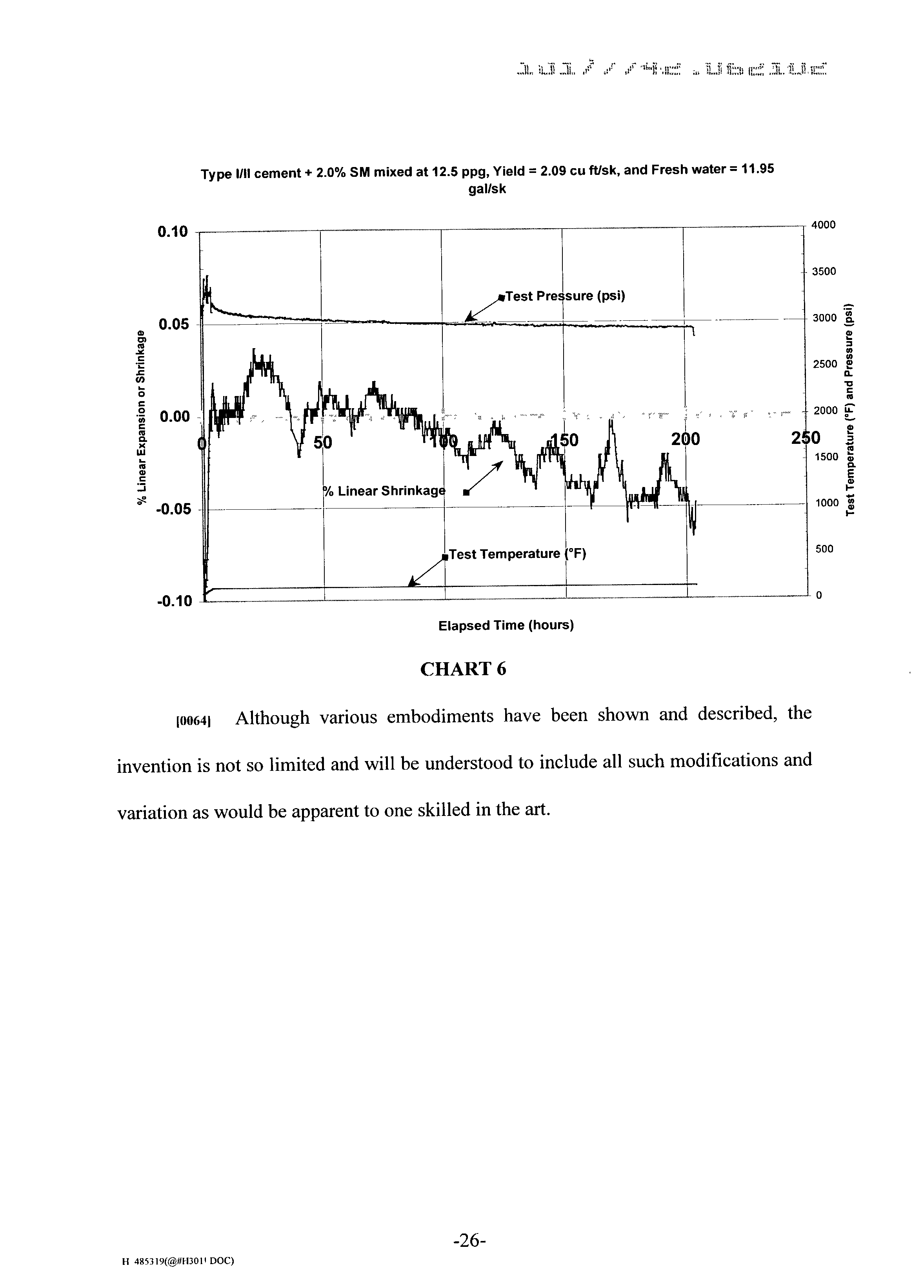
- Chart 4 provides expansion/shrinkage data for a Type I/II cement, which is widely known and used in the industry and is a construction grade cement similar to APT Class A cement.
- the cement slurry was prepared at 15.6 PPG.
- Expanding cement additive EC-1 was added at 10% by weight.
- a dispersant available from BJ Services Company under the name CD-32 was added at 0.4% by weight of the cement. The dispersant assists in the designing of normal density, low loss slurries that can easily be pumped in turbulent flow.
- the mixture yielded 1.29 cubic feet per sack of cement; and 5.57 gallons of fresh water per sack of cement were used.
- the test was conducted at 140° F. and 3000 psi curing pressure. Test temperature and percent linear expansion are reported.
- Chart 5 provides expansion/shrinkage data for a Class G cement, an API grade cement widely known and used in the industry.
- the cement slurry was prepared at 15.8 PPO.
- the mixture yielded 1.15 cubic feet per sack of cement; and 4.99 gallons of fresh water per sack of cement were used.
- the test was conducted at 140° F. and 3000 psi curing pressure. Test temperature, curing pressure and percent linear expansion are reported.
Abstract
Description
- This application claims priority to the Provisional Application No. 60/300,202, entitled “Cement Expansion/Contraction Test Apparatus,” filed Jun. 22, 2001.
- 1. Field of the Invention
- The invention relates to an apparatus and method for use in the measurement of fluids used in the field of oil and gas recovery. More particularly, this invention relates to an apparatus such as a mold adapted to detect the expansion or shrinkage of cement as the cement is exposed to simulated down-hole conditions, such as high-pressure, high-temperature applications. A method for measuring the expansion or shrinkage of the cement is also disclosed.
- Description of the Related Art
- It is a fact that cement will undergo chemical shrinkage when it sets. The chemical shrinkage—or the hydration volume reduction (HVR)—of a cement slurry is a direct result of water chemically reacting with the cement clinker crystalline materials forming calcium silicate crystals. The chemical shrinkage of the slurry can be not insubstantial, e.g. seven percent of its original volume, depending on the slurry formulation. The matrix volume change of the cement slurry can lead to poor cement bonding or to the creation of micro-annuli. These micro-channels or poorly bonded areas may allow well fluids like gas, oil, steam, water, and/or the combination of fluids to migrate to the surface or to other zones of the well. The migration of well fluids will result in lower production revenue. Additionally, the migration of well fluids can increase well maintenance costs, increase casing corrosion, and reduce the life of the well. The formation of micro-annuli may require a secondary cement job or squeeze cementing, thus increasing the total well cost. The migration of well fluids can also lead to complete loss of the well due to blowout. In injection wells, the poor cement bonding can lead to a higher injection cost and lower well efficiency. These well fluids can migrate, contaminate, and pollute fresh water aquifers.
- It is uncommon for oil and gas well service companies to evaluate, test or measure this important cement property. This is due primarily to a lack of the appropriate efficient and accurate equipment to continuously measure the cement shrinkage or expansion while it is curing under humid environment and under down-hole temperature and pressure.
- Few methods and ideas have been tested to accurately measure volume change of cement slurry. M. E. Chenevert and B. K. Shrestha from the University of Texas have written a SPE paper on the Chemical Shrinkage Properties of Oilfield Cement. The apparatus used in the experiment consists of a high-pressure cell, a high-pressure injection pump with pressure transducer and digital gauge, a heating jacket, a vacuum pump, autoclave high-pressure tubing and valves, and an electronic thermostat with a sensing thermocouple. For each test, a thin-walled lead tube with a 1.375-inch diameter by 4 inches long is used. The lead tubes containing the slurry is capped and placed inside the high-pressure cell and inside the heating jacket. The high-pressure injection pump is used to inject mineral oil around the test sample and to the control pressure during the test. The desired heat is applied to the test sample with the heating jacket and controlled with the thermostat.
- The volumetric property of the slurry is measured directly by the volume of mineral oil injected. Therefore, it is necessary to calibrate the pump and establish the relationship between the volume of oil injected to the positive-displacement pump read-out. During a test, if the temperature of the test cell changes then the pressure will change too. The behavior is due to the thermal expansion or contraction of the mineral oil. Depending on the temperature change, the pressure regulator will activate the pump by removing or adding mineral oil to the system. These can indicate a false reading of cement volumetric changes. Therefore, it is necessary to establish a mineral oil thermal expansion coefficient for each test temperature. The mineral oil correction factor will be used in slurry volumetric calculations.
- Other authors, Reza Ghofrani and Heiko Plack, wrote SPE/IADC 25697 (“CaO-and/or MgO-Swelling Cements: A Key for Providing a Better Annular Sealing?”). In their experiment, they use a different apparatus to measure the matrix volume change in cement slurry. The apparatus consists of a test cell, a gear mechanism, a floating piston, potentiometer, autoclave and chart recorder. The test cell is divided into three-sections: 1) a water reservoir; 2) a sample chamber; and 3) a measuring head. A sintered metal disk and a filter paper are mounted at the bottom of the cement sample. Below the metal disk is a cavity filled with water. A metal plug with sealed assembly is used to cap the bottom of the water chamber. The autoclave curing pressure is transmitted to the cement during the test by the way of the metal plug to the water and to the cement. This will allow the cement to absorb additional water as required during the hydration process. On the top of the cement sample is a rubber cup sleeve that seals the cement against the pressurizing fluid (mineral oil). A floating piston is installed on top of the rubber cup sleeve. The axial motion of the piston caused by the changes in the matrix volume is converted to a rotational motion by a gear mechanism. The gear mechanism will alter the position of the pointer across the potentiometer resistor. The shifting position of the pointer across the resistor provides a variation of the voltage signal. The measured voltages along with the autoclave-temperature and pressure are monitored continuously by means of a chart recorder. The matrix volume change is calculated using the calibration chart. The calibration chart is expressed as piston height versus voltage signal reading.
- One advantage of the Ghofrani/Plack apparatus is that fresh water is pushed into the cement matrix while curing. The test data from the apparatus can be subjective due to the measuring head design. The rubber cup sleeve that seals the cement against the mineral oil can absorb some of the displacement movement or it can swell to provide a positive movement for the piston. The mechanical tolerances on the gear mechanism can affect equipment performance from one unit to the other. The volumetric change in some slurries may be in the micro-inches spectrum and converting it to axial motion by the piston, to a rotational movement by the gear mechanism, and to electrical signal by the potentiometer. The measuring head design may be impractical for field application accuracy may be sacrifice. Currently, none of these concepts has been built commercially to support the oil well industry.
- An apparatus is described for measuring volumetric changes in cement as the cement is exposed to a given pressure and temperature in a high-pressure high-temperature chamber. In some embodiments, the apparatus has a first section adjacent a base and a second a second section movably attached to the first section, the second section adjacent the base. The first section, the second section, and the base may define a mold into which a measurable amount of cement may be placed. The apparatus may include a sensor that is functionally associated with at least one of the sections. The sensor may be adapted to measure the movement of the first and second sections relative to one another in response to volumetric changes in the cement when the cement is exposed to simulated down-hole pressures and temperatures. The apparatus may include a seal between the first and second sections, in some embodiments.
- In some embodiments, the apparatus includes a fastening assembly, which may comprise a first bolt surrounded by a first spring and having a threaded end, the first bolt passing through a first hole in the second section and threadedly engaged with a first threaded hole in the first section, and a second bolt surrounded by a second spring and having a threaded end, the second bolt passing through a second hole in the second section and threadedly engaged with a second threaded hole in the first section, the springs adapted to bias the second section into contact with the first section.
- In some embodiments, an apparatus is described having a means for moving with volumetric changes in the cement movably attached to the first section, the means for moving adjacent the base. The apparatus may include a sensing means contacting at least one of the sections for measuring the movement of the means for moving in response to volumetric changes in the cement when the cement is exposed to high pressure and high temperature, or a means for sealing.
- Also described is a method of measuring volumetric changes in cement as the cement is exposed to a given pressure and temperature in a high-pressure high-temperature chamber utilizing the molds described herein, filling the mold with cement, placing the mold into the high-pressure high-temperature chamber, raising the pressure to a given value and the temperature to a given value, changing the pressure to other given values and the temperature to other given values, and recording data from the sensor over time.
- In some aspects, a basket is described which may facilitate the processing of multiple molds at the same time. The basket may include mounting rods, a top plate, and a bottom plate.
- FIG. 1 shows a top view of one embodiment of the present invention having a mold mounted inside a high-pressure high-temperature chamber.
- FIG. 2 shows a top view of an exploded view of a mold of one embodiment of the present invention.
- FIG. 3 shows an exploded side view of one embodiment of the present invention having anchor blocks.
- FIG. 4 shows a side view of one embodiment of the present invention having a basket.
- While the invention is susceptible to various modifications and alternative forms, specific embodiments have been shown by way of example in the drawings and will be described in detail herein. However, it should be understood that the invention is not intended to be limited to the particular forms disclosed. Rather, the invention is to cover all modifications, equivalents, and alternatives falling within the spirit and scope of the invention as defined by the appended claims.
- Illustrative embodiments of the invention are described below as they might be employed in volumetric measurements. In the interest of clarity, not all features of an actual implementation are described in this specification. It will of course be appreciated that in the development of any such actual embodiment, numerous implementation-specific decisions must be made to achieve the developers' specific goals which will vary from one implementation to another. Moreover, it will be appreciated that such a development effort might be complex and time-consuming, but would nevertheless be a routine undertaking for those of ordinary skill in the art having the benefit of this disclosure. Further aspects and advantages of the various embodiments of the invention will become apparent from consideration of the following descriptions and drawings.
- In some embodiments, a modified high-temperature (HPHT)
cement curing chamber 90 is described. TheHPHT curing chamber 90 consists of autoclave test cell with heaters, temperature controller, and hydraulic pump with pressure regulator. Thus, the HPHT curing chamber may simulate down hole pressures and temperatures. The expansion/contraction mold 50 is fitted inside theHPHT curing chamber 90. Outside theHPHT curing chamber 90 is a high-pressure spring loaded linear displacement transducer 80 (LDT) with Autoclave fittings. The signal fromLDT 80 is processed by the Data Acquisition Unit 82 (DAU) and then theDAU 82 communicates the process signal to adevice 84 such as computer or a chart recorder. The computer or the chart recorder will store the data from the test. The equipment will continuously monitor cement expansion, before and after cement hydration process. The equipment will also measure cement shrinkage continuously after the cement has set. Measurements may be taken under a humid environment and under down-hole temperature and pressure. The innovative mold design will allow cement movement or volumetric changes in all three directions (“X”, “Y”, and “Z” axis). See FIGS. 1, 2, and 3. Using amold basket 40, theHPHT curing chamber 90 can be fitted to accommodate threemolds 50 stacked one on top of the other. Fitted with threeLDTs 80 and appropriate electronic accessories, the computer can simultaneously process and store test data from threedifferent cement formulations 10 including test temperature and pressure. Of course, as would be apparent to one of ordinary skill in the art having the benefit of this disclosure, the number ofcement formulations 10 andmolds 50 is not limited to three; rather, any number ofcement formulations 10 could processed inmolds 50 by modifying the size and shape of thechamber 90 ormolds 50, for example. - Advantages of the apparatus include the following: The sample of cement is not subject to mechanical restriction on the sample, as the mold design allows the
cement 10 to expand or shrink in three axes. By way of example, threedifferent slurry formulations 10 can be tested simultaneously at the same bottom-hole temperature and pressure. The apparatus can independently measure the linear expansion or contraction of the threedifferent cement formulations 10. The (HPHT)linear displacement transducer 80 can easily be calibrated with a micrometer. The cement volumetric change is transmitted from themold body 50, to theLDT 80, and to the computer. A calibrated (HPHT)linear displacement transducer 80 will provide a direct reading of expansion or contraction. There is no need for elaborate mathematical calculations. Confining pressure and temperature will not affect the performance of theLDT 80. Therefore, it will not affect test measurements. It is not necessary to determine or calibrate the coefficient of expansion of the confining fluids. Thecement 10 is cured under a humid environment and under down-hole temperature and pressure. ExistingHPHT curing chambers 90 can be modified and fitted for the expansion or contraction testing. At the end of the volumetric test, theset cement 10 can be tested for permeability. The modifiedHPHT curing chamber 90 can still be used for compressive strength testing. No need exists for a different machine or pressurized curing vessel. Further, off-the-shelf software can be used to monitor the test. No need exists to invest on different software. An old 468 computer or higher with Windows 95 can be used to monitor and store the test data. - In some embodiments, a standard
cement curing chamber 90 may be modified to accept a high-pressure/high temperaturelinear distance transducer 80 as disclosed herein. In some embodiments, an expansion/shrinkage mold 50 is fabricated along with the necessary fittings and accessories. An electronic circuit may be assembled to measure, collect, and store the test data in a PC computer. - Test data generated from some embodiments can continuously measure cement expansion or shrinkage accurately under humid conditions and at down-hole temperature and pressure. The design of the
mold 50 allows thecement 10 to move freely in three (X, Y and Z) axes while curing at down-hole conditions. In this case, thecement slurry 10 is assumed to expand or shrink uniformly in three axes as long as the slurry is subjected to the same confining conditions. Thelinear distance transducer 80 will detect any movement directly from two parallel planes inside themold 50 along the X-axis. Alternatively, threelinear distance transducers 80 may be utilized to measure movement in the X, Y, and Z directions. - After assembly of the apparatus, before any testing, the linear distance transducer in conjunction with the electronic data acquisition unit is calibrated accurately using a Venier caliper. Once the calibration of the linear displacement transducer is established, re-calibration is not necessary on the preceding test. Another feature of the invention is the apparatus does not require any complicated calculations to function. The
cement slurry 10,mold 50, confiningfluids 12, andtest cell 90 are exposed to the same test conditions at the same time. Therefore, the coefficient of expansion of themold 50, confiningfluid 12, andtest cell 90 does not interfere with the test data. In addition, theslurry 10 is cured under humid condition at down-hole temperature and pressure at all time during the test. - Based on testing (see the attached test data), it has been determined that the
cement 10 may continuously change its dimensions several days or more than a week after it has been mixed. In order to maximize the equipment efficiency, it is preferable that a curingchamber 90 is used that will accommodate multiplelinear distance transducers 80 at the same time. - Embodiments of the invention will now be described with reference to the accompanying figures. Referring to FIG. 1, one embodiment of the present invention is shown having a
mold 50 inside a high-pressure high-temperature curing chamber 90. High-pressure high-temperature curing chamber 90 is any standard high-pressure high-temperature test cells commercially available, such as Chandler Engineering Curing Vessel model #7-700-5, from Chandler Engineering, Tulsa, Okla. Thischamber 90 thus can simulate elevated down-hole pressures and temperatures. -
Mold 50 is shown to be comprised of afirst section 60 and asecond section 70 as described more fully hereinafter.Mold 50 may be filled withcement 10. - Functionally associated with
second section 70 issensor 80.Sensor 80 may be a linear displacement transducer.Sensor 80 may contactsecond section 70, for example. A standard high-pressure high-temperature curing chamber 90 typically is not equipped with asensor 80, but can be modified to insertsensor 80.Sensor 80 may be a spring-loaded linear displacement transducer or any other type of linear displacement transducer known by one of ordinary skill in the art having the benefit of this disclosure, such as an electromagnetic linear displacement transducer. Electrically connected to the linear displacement transducer is adata acquisition unit 82 which collects readings fromsensor 80. - Electrically connected to
data acquisition unit 82 is adevice 84 for storing and displaying the data from thedata acquisition unit 82 over time. For example,device 84 may be a computer or a chart recorder. - In FIG. 1,
mold 50 is shown inmold basket 40 described more fully herein. In the embodiment shown, themold 50 includes mountingholes 41 for attaching themolds 50 to abasket 40 as more fully described herein. Themold basket 40 is placed into the high-pressure high-temperature chamber 90. A pressurizingmedium 12 is then pumped into the chamber to increase the pressure. This pressurizing medium may be water, or oil, or any other fluid capable of increasing the pressure withinchamber 90 by being pumped into thechamber 90, by a hydraulic pump (not shown) for example. Thechamber 90 also includes heaters (not shown) for increasing the temperature within the chamber. - As shown in FIG. 2, a
seal 52 is placed between the twosections first section 60 and thesecond section 70 from contacting each other.Seal 52 may be an O-ring, or a low-durometer rubber seal, a thin wall tygon tubing, or any other type of seal will allow the sections to be compressed together, as described more fully herein, while preventing the cement from leaking out of the sections. - As shown in FIG. 2,
first section 60 may be comprised ofsides Sides angle 66. In this embodiment,angle 66 is 90 degrees. Further, each ofsides mating surface second section 70 as described more fully herein. - Similarly,
second section 70 may be comprised ofsides Sides angle 76. In this embodiment,angle 76 is 90 degrees. Also shown in FIG. 2 iscontact location 77 of thesecond section 70. Further, each ofsides mating surface first section 60 as described more fully herein. - As shown in FIG. 2, in this embodiment,
second section 70 is movably attached to thefirst section 60 by a fastening assembly. The fastening assembly in this embodiment is comprised as follows. Afirst bolt 20 having a threaded end is surrounded by aspring 24. Thefirst bolt 20 passes through ahole 71 inmating surface 78 of thesecond section 70. The threaded end of thefirst bolt 20 is screwed into the threadedhole 61 inmating surface 68 of thefirst section 60. In this way,spring 24 biases thesecond section 70 toward thefirst section 60 at mating surfaces 78 and 68, respectively. As described above,first section 60 andsecond section 70 are separated byseal 52. - A
first washer 22 also may be utilized aroundbolt 20. Afirst alignment pin 26 may also be used to ensure that the second section moves in a linear fashion as described herein and prevents the shearing offirst bolt 20.First alignment pin 26 is pressed into a hole (shown in FIG. 2 but not numbered) inmating surface 68 and engages a second hole (shown in FIG. 2 but not numbered) inmating section 78 ofsecond section 70. - The fastening assembly also includes a
second bolt 30 having a threaded end. Thesecond bolt 30 is surrounded by aspring 34. Thesecond bolt 30 passes through ahole 73 inmating surface 79 of thesecond section 70. The threaded end of thefirst bolt 20 is screwed into the threadedhole 63 inmating surface 69 of thefirst section 60. In this way,spring 34 biases thesecond section 70 toward thefirst section 60 at mating surfaces 79 and 69, respectively. As described above, the first and section sections are separated byseal 52. - A
second washer 32 also may be utilized aroundbolt 30. Asecond alignment pin 36 may also be used to ensure that thesecond section 70 moves in a linear fashion as described herein and prevents the shearing ofsecond bolt 30.Second alignment pin 36 is pressed into a hole (shown in FIG. 2 but not numbered) inmating surface 69 and engages a second hole (shown in FIG. 2 but not numbered) inmating section 79 ofsecond section 70. Of course, any type of fastening assembly which movably attachesfirst section 60 andsecond section 70 that is known to one of ordinary skill in the art having the benefit of this disclosure would also be acceptable. - Referring to FIG. 3, an exploded side view of one embodiment of the present invention is shown. The first section is fixedly attached to the
base 54 viabolt 11. Thesecond section 70 is movably attached to thefirst section 60 via the fastening assembly described above. Thesecond section 70 thus rests on thebase 54 and may move relative to the base in a horizontal direction, unlike thefirst section 60 which is fixedly attached tobase 54. - The
mold 50 may include afirst anchor block 14 and asecond anchor block 15. First and second anchor blocks 14 and 15 may be inserted intochannels section sections anchor block anchor bolt cement 10 may adhere, as described more fully herein. -
Channels channels - A
single mold 50 may be placed into the high-pressure high-temperature chamber. However, it is often desirable to have multiple cement samples in multiple molds processed under the same temperature and pressure conditions. Therefore,multiple molds 50 may be placed in amold basket 40 as more fully described herein with respect to FIG. 4. As shown in FIGS. 1, 2, and 3,molds 50 may include at least one mounting hole for attaching themold 50 to the basket. The mounting holes 41 may be in themold lid 94 and inbase 54. - Additionally, while not necessary, the
mold 50 may have alid 94 to cover themold 50, once filled withcement 10, to prevent spillage thereof. Further, anothersensor 80, such as a linear displacement transducer, may contact thelid 94 to measure the expansion or shrinkage of the concrete in the Z-direction, as the anchor blocks move relative to themold 50. Aseal 52 may be placed between the lid and the first andsections Seal 52 may be an O-ring, low durometer rubber seal, or tygon tubing, for example. Further,lid 94 may be movably attached to the first andsecond sections - In operation, the
sensor 80 is calibrated. Ifsensor 80 is a linear displacement transducer, thelinear distance transducer 80 in conjunction with thedata acquisition unit 82 is calibrated using a Vernier caliper. - A
mold 50 is constructed as described above. Thecement 10 to be tested is mixed and placed inmold 50.Mold 50 is then inserted into the high-pressure high-temperature chamber 90 solely, or inbasket 40 stacked along withother molds 50. - Once in the high-pressure high-
temperature chamber 90, the sensor may be functionally associated with themold 50. For example, the sensor may be brought into contact with thecontact location 77 of the movablesecond section 70 of themold 50. Thesensor 80 is in constant contact with thecontact location 78, whether the cement shrinks or expands, by virtue of either a spring or electromagnetic forces of the linear displacement transducer, when used. - The high-temperature high-
pressure chamber 90 is then activated to bring the contents therein to a given operating temperature and pressure simulating downhole conditions. Once thecement 10 sets, thecement 10 attaches to anchorbolts - Volumetric changes of the
cement 10 is then monitored as follows.First section 60 is fixed to themold base 54 and therefore does not move. If thecement 10 expands,second section 70 ofmold 50 moves towardsensor 80, as the force of the current expanding overcomes the force ofsprings second section 70 moves linearly towardsensor 80, due in part to alignment pins 26 and 36, which are parallel to the axis ofsensor 80. Assecond section 70 moves towardsensor 80,sensor 80 sends data to thedata acquisition unit 82, which also stores the temperature and pressure settings of thechamber 90.Device 84 then stores the data from theacquisition unit 82 with respect to time and may display the results, if desired. - Additionally, the expansion of the
cement 10 also forces anchor blocks 14 and 15 to move upwardly inchannels mold 50, as thecement 10 is attached to anchorbolts - In some instances, the
cement 10 does not expand, but shrinks. If thecement 10 shrinks, movablesecond section 70 ofmold 50 moves away fromsensor 80, as the force of the cement shrinking overcomesseal 52. Once set, thecement 10 attaches to the anchor blocks 14 and 15. As thecement 10 shrinks, thesecond section 70 moves towardfirst section 60 and away fromsensor 80. Thus, the first andsecond sections seal 52 is comprised of a resilient material such as rubber, the seal compresses. - The
sensor 80 maintains contact with thesecond section 70, as thesensor 80 has a biasing means, such as a spring or an electromagnetic field, to ensure constant contact. Thesecond section 70 moves linearly towardsensor 80, due in part to alignment pins 26 and 36, which are parallel to the axis ofsensor 80. Assecond section 70 moves towardsensor 80,sensor 80 sends data to thedata acquisition unit 82, which also stores the temperature and pressure settings of thechamber 90.Device 84 then stores the data from theacquisition unit 82 with respect to time an may display the results, if desired. - As
second section 70 moves away fromsensor 80,sensor 80 sends data to thedata acquisition unit 82, which also stores the temperature and pressure settings of thechamber 90.Device 84 then stores the data from theacquisition unit 82 with respect to the an may display the results, if desired. - Referring to FIG. 4, a side view of multiple (e.g. three)
molds 50 placed in abasket 40 is shown. In this embodiment,basket 40 includes abottom plate 46. In this embodiment, four mountingrods 42 are connected to thebottom plate 46. Bottom plate has mounting holes through which the mountingrods 42 may be inserted. Connected to the opposite end of the mountingrods 42 istop plate 44. Bothbottom plate 46 andtop plate 44 are held in place in this embodiment by being threadedly locked to mounting nuts 49. - In some embodiments, a
removable handle 48 is attached to thetop plate 44 to facilitate the operator's handling of thebasket 40. -
Multiple molds 50 may be placed between thetop plate 44 and thebottom plate 46. In the embodiment shown in FIG. 4, three molds—50 a, 50 b, and 50 c—are shown inbasket 40, although any number ofmolds 50 could be housed inbasket 40. Afirst mold 50 a rests on bottom plate 46 a. As described above,mold 50 a may include mountingholes 41 within thelid 94 a and the base 54 a through which mountingrods 49 are inserted. - A
second mold 50 b may then be stacked above thefirst mold 50 a. Again,second mold 50 b includes a plurality of mounting holes inlid 94 b andbase 54 b to accommodate the plurality of mountingrods 42.Base 54 b of thissecond mold 50 b is connected to the mountingrods 42 at a location such that the base 54 b of thesecond mold 50 b does not contact thelid 94 a of thefirst mold 50 a. Thus,gap 43 a is present between thefirst mold 50 a andsecond mold 50 a. This is accomplished by attachingflanges 45 to the mountingrods 42 at a location above thefirst mold 50 a such that agap 43 a is created. Thesecond mold 50 b is functionally associated with the mountingrods 42 viaflanges 45. This gap allows thecement 10 in thefirst mold 50 a to expand in the vertical direction, if needed. - A
third mold 50 c may then be stacked above thesecond mold 50 b.Flanges 45 may be connected to the mountingrods 42 above thesecond mold 50 b. Thesecond mold 50 b may be connected to the mountingrods 42 byflanges 45 such that agap 43 b exists between thesecond mold 50 b and thethird mold 50 c. This gap allows thecement 10 in thesecond mold 50 b to expand in the vertical direction, if needed. - Finally,
top plate 44 of thebasket 40 may be connected to the mountingrods 42 such thatgap 43 c exists to allow cement in thethird mold 50 c to expand in the vertical direction, if needed.Top plate 44 ofbasket 40 may include mounting holes to accommodate the mountingrods 42.Gap 43 c may be created by any number of ways, such as those known to one of ordinary skill in the art having the benefit of this disclosure. For example,flanges 45 as described above could be utilized. Alternatively, the diameter ofrods 49 may be reduced at aabove lid 94 c such thatgap 43 c is created. If the mounting holes in thetop plate 44 are smaller than the mountingholes 41 in themold lid 94 c, thegap 43 c will be created. - Additionally, three
linear displacement transducers 80 may be connected to themolds 50, one sensor per mold, to take measurements of three molds simultaneously. In this way, the device such as a computer can simultaneously process and store test data from three different cement formulations including test temperature and pressure. - Chart #1 and Chart #2 demonstrate the results of expansion and contraction tests performed using the apparatus of the present invention. Chart #1 provides expansion test data for a sample of API Class “A” Cement, which is widely known and used in the oil and gas well service industry. The cement was mixed at 15.6 PPG (pounds per gallon). An expanding cement additive available from BJ Services Company under the name EC-1 was added to the cement preparation to provide early expansion of the set cement. The EC-1 was added at an amount of 10% by weight of the cement. Linear expansion and slurry temperature data are reported. Chart #2 provides contraction test data for API Class “A” Cement mixed at 12.5 PPG. Sodium metasilicate, an extender used to produce an economical, low density slurry was added to the cement at an amount of 2% by weight. Calcium chloride, a cement accelerator, was added at an amount of 1% by weight. Slurry temperature and percent linear contraction results were reported.

- Charts 3, 4, 5, and 6 provide the results of additional expansion and contraction tests conducted using the invention disclosed herein. Chart 3 provides expansion data for a cement slurry available from BJ Services Company under the name Liquid Stone®. An expanding cement additive available from BJ Services Company under the name EC-2 was added to the Liquid Stone® preparation at 7.5% by weight of the slurry. The test to measure linear expansion, test pressure and test temperature was conducted at 248° F.
- Chart 4 provides expansion/shrinkage data for a Type I/II cement, which is widely known and used in the industry and is a construction grade cement similar to APT Class A cement. The cement slurry was prepared at 15.6 PPG. Expanding cement additive EC-1 was added at 10% by weight. A dispersant available from BJ Services Company under the name CD-32 was added at 0.4% by weight of the cement. The dispersant assists in the designing of normal density, low loss slurries that can easily be pumped in turbulent flow. The mixture yielded 1.29 cubic feet per sack of cement; and 5.57 gallons of fresh water per sack of cement were used. The test was conducted at 140° F. and 3000 psi curing pressure. Test temperature and percent linear expansion are reported.
- Chart 5 provides expansion/shrinkage data for a Class G cement, an API grade cement widely known and used in the industry. The cement slurry was prepared at 15.8 PPO. The mixture yielded 1.15 cubic feet per sack of cement; and 4.99 gallons of fresh water per sack of cement were used. The test was conducted at 140° F. and 3000 psi curing pressure. Test temperature, curing pressure and percent linear expansion are reported.


- Although various embodiments have been shown and described, the invention is not so limited and will be understood to include all such modifications and variation as would be apparent to one skilled in the art.
Claims (37)
Priority Applications (2)
| Application Number | Priority Date | Filing Date | Title |
|---|---|---|---|
| US10/177,742 US6817238B2 (en) | 2001-06-22 | 2002-06-21 | Cement expansion/contraction test apparatus |
| US10/867,624 US6918292B2 (en) | 2001-06-22 | 2004-06-15 | Cement expansion/contraction test method |
Applications Claiming Priority (2)
| Application Number | Priority Date | Filing Date | Title |
|---|---|---|---|
| US30020201P | 2001-06-22 | 2001-06-22 | |
| US10/177,742 US6817238B2 (en) | 2001-06-22 | 2002-06-21 | Cement expansion/contraction test apparatus |
Related Child Applications (1)
| Application Number | Title | Priority Date | Filing Date |
|---|---|---|---|
| US10/867,624 Division US6918292B2 (en) | 2001-06-22 | 2004-06-15 | Cement expansion/contraction test method |
Publications (2)
| Publication Number | Publication Date |
|---|---|
| US20030033893A1 true US20030033893A1 (en) | 2003-02-20 |
| US6817238B2 US6817238B2 (en) | 2004-11-16 |
Family
ID=26873598
Family Applications (2)
| Application Number | Title | Priority Date | Filing Date |
|---|---|---|---|
| US10/177,742 Expired - Lifetime US6817238B2 (en) | 2001-06-22 | 2002-06-21 | Cement expansion/contraction test apparatus |
| US10/867,624 Expired - Fee Related US6918292B2 (en) | 2001-06-22 | 2004-06-15 | Cement expansion/contraction test method |
Family Applications After (1)
| Application Number | Title | Priority Date | Filing Date |
|---|---|---|---|
| US10/867,624 Expired - Fee Related US6918292B2 (en) | 2001-06-22 | 2004-06-15 | Cement expansion/contraction test method |
Country Status (1)
| Country | Link |
|---|---|
| US (2) | US6817238B2 (en) |
Cited By (14)
| Publication number | Priority date | Publication date | Assignee | Title |
|---|---|---|---|---|
| US20050152432A1 (en) * | 2004-01-13 | 2005-07-14 | Halliburton Energy Services, Inc. | Method and apparatus for testing cement slurries |
| US20110193564A1 (en) * | 2010-02-08 | 2011-08-11 | Youssef Elmarsafawi | Cement expansion measurement apparatus and method |
| CN102539655A (en) * | 2010-12-23 | 2012-07-04 | 河海大学 | Mold for measuring horizontal direction contract value of concrete |
| CN106768153A (en) * | 2016-12-29 | 2017-05-31 | 中国人民解放军63926部队 | A kind of slurry consolidation cubical contraction test device and method of testing |
| CN108507883A (en) * | 2018-04-28 | 2018-09-07 | 四川大学 | Rock damage mechanics test system under deep ground high temperature and high pressure environment |
| CN110043221A (en) * | 2019-05-31 | 2019-07-23 | 中国海洋石油集团有限公司 | A kind of device measuring cementing concrete ring microannulus |
| CN110181663A (en) * | 2019-05-31 | 2019-08-30 | 中国海洋石油集团有限公司 | A kind of grout cures simulated formation mold |
| CN110208503A (en) * | 2019-05-31 | 2019-09-06 | 中国海洋石油集团有限公司 | A kind of instrument measuring cementing concrete ring microannulus |
| CN110470596A (en) * | 2019-09-12 | 2019-11-19 | 西南石油大学 | Behavior of Hardened Cement Paste cementing strength in-situ testing device and method under a kind of operating condition of simulation high temperature and pressure underground |
| CN111335874A (en) * | 2020-03-20 | 2020-06-26 | 中国石油大学(北京) | Oil-gas well cementing cement packing capacity detection device and detection method thereof |
| JP2021028625A (en) * | 2019-08-09 | 2021-02-25 | 胡金霞 | Self-shrinkage test system for cement-based member |
| CN112684150A (en) * | 2020-12-11 | 2021-04-20 | 马鞍山市国林建材有限公司 | Cement ring expansion performance test equipment for production of Z-shaped concrete hollow building blocks |
| WO2021231916A1 (en) * | 2020-05-15 | 2021-11-18 | Aramco Services Company | System and method for testing cement |
| CN116183886A (en) * | 2023-04-24 | 2023-05-30 | 北京慕湖仪器制造有限公司 | Scaleless cement Raschel expansion tester and stability measuring method |
Families Citing this family (39)
| Publication number | Priority date | Publication date | Assignee | Title |
|---|---|---|---|---|
| US7066038B2 (en) * | 2002-04-15 | 2006-06-27 | Amebis Intellectual Properties Limited | Material stability test system |
| ES2329342T3 (en) * | 2002-12-11 | 2009-11-25 | Ipsen International Gmbh | PROCEDURE FOR MEASURING THE AMOUNT OF A COMPONENT ABSORBED BY A METAL PART IN THE COURSE OF A THERMOCHEMICAL TREATMENT. |
| WO2005065411A2 (en) * | 2003-12-31 | 2005-07-21 | Saudi Arabian Oil Company | Test apparatus for direct measurement of expansion and shrinkage of oil well cements |
| US7380466B2 (en) * | 2005-08-18 | 2008-06-03 | Halliburton Energy Services, Inc. | Apparatus and method for determining mechanical properties of cement for a well bore |
| JP2009510452A (en) * | 2005-09-30 | 2009-03-12 | プラスティック テクノロジーズ インコーポレイテッド | System for gas permeation testing |
| US7549320B2 (en) * | 2007-01-11 | 2009-06-23 | Halliburton Energy Services, Inc. | Measuring cement properties |
| US7621186B2 (en) | 2007-01-31 | 2009-11-24 | Halliburton Energy Services, Inc. | Testing mechanical properties |
| JP2010533873A (en) * | 2007-07-19 | 2010-10-28 | プラスティック テクノロジーズ インコーポレイテッド | Gas permeation test system |
| CN101183093B (en) * | 2007-11-08 | 2011-07-27 | 武汉科技大学 | Measuring equipment of non-metallic material high-temperature expansive power and method of use thereof |
| US8601882B2 (en) | 2009-02-20 | 2013-12-10 | Halliburton Energy Sevices, Inc. | In situ testing of mechanical properties of cementitious materials |
| US8783091B2 (en) | 2009-10-28 | 2014-07-22 | Halliburton Energy Services, Inc. | Cement testing |
| FR2952181B1 (en) * | 2009-11-04 | 2016-04-29 | Centre Nat Rech Scient | DEVICE FOR MEASURING THE ACTIVITY OF A LIQUID IN A COMPLEX MEDIUM AND ASSOCIATED METHOD |
| US8156798B1 (en) | 2010-07-09 | 2012-04-17 | Hongfeng Bi | High pressure high temperature fluid densitometer |
| CN102401769B (en) * | 2010-09-10 | 2013-12-04 | 中国石油化工股份有限公司 | Oil well cement high-temperature high-pressure compressive stress strain system and test method thereof |
| CN102401770B (en) * | 2010-09-10 | 2014-05-14 | 中国石油化工股份有限公司 | High-temperature high-pressure tensile stress strain system of oil well cement and test method thereof |
| US8949067B1 (en) * | 2010-09-17 | 2015-02-03 | Ofi Testing Equipment, Inc. | Device and method for measuring material volume changes |
| FR2965925B1 (en) * | 2010-10-12 | 2015-06-19 | Total Sa | MEASURING THE PROPERTIES OF SAMPLES OF HIGH-PRESSURE CURING COMPOSITIONS |
| US8960013B2 (en) | 2012-03-01 | 2015-02-24 | Halliburton Energy Services, Inc. | Cement testing |
| US9429558B2 (en) * | 2012-06-26 | 2016-08-30 | Baker Hughes Incorporated | Multi-function testing apparatus for cement and methods of using the same |
| US8794078B2 (en) | 2012-07-05 | 2014-08-05 | Halliburton Energy Services, Inc. | Cement testing |
| CN103245773B (en) * | 2013-04-19 | 2015-09-09 | 中国石油天然气股份有限公司 | Cement paste for well cementation volume change tester and method of testing |
| US9557315B2 (en) * | 2013-07-29 | 2017-01-31 | Schlumberger Technology Corporation | Confining pressure measurement for zonal isolation evaluation |
| WO2015065396A1 (en) * | 2013-10-30 | 2015-05-07 | Halliburton Energy Services, Inc. | Modular sensed annular well apparatus for cement testing |
| GB2538164B (en) * | 2013-11-12 | 2020-04-29 | Halliburton Energy Services Inc | Displacement measurement cement testing |
| EP3126620A4 (en) | 2014-04-04 | 2017-11-29 | Services Pétroliers Schlumberger | Wellbore cement simulator |
| US9671385B2 (en) * | 2014-05-15 | 2017-06-06 | H. Joseph Buhac | Compaction testing sampler assembly |
| US9869788B2 (en) * | 2014-07-29 | 2018-01-16 | Schlumberger Technology Corporation | Seismic detector |
| MX2017010617A (en) | 2015-03-02 | 2017-12-07 | Halliburton Energy Services Inc | Optical measurement system. |
| CN105334306B (en) * | 2015-10-23 | 2017-04-12 | 西安近代化学研究所 | Detachable sample cage for explosive volume expansion coefficient measuring device |
| CN105675850B (en) * | 2016-01-27 | 2017-11-17 | 三峡大学 | A kind of test method for studying expansion cement slurry long-time stability |
| US11041794B2 (en) * | 2016-08-31 | 2021-06-22 | Command Alkon Incorporated | Rheological probe |
| US11420358B2 (en) * | 2016-12-22 | 2022-08-23 | Command Alkon Incorporated | Methods and system for handling fresh concrete |
| CN107478812B (en) * | 2017-07-10 | 2019-07-02 | 三峡大学 | Rock And Soil large dosage expansion cement slurry expansion process visualization device and application method |
| US10450494B2 (en) | 2018-01-17 | 2019-10-22 | Bj Services, Llc | Cement slurries for well bores |
| WO2019157172A2 (en) * | 2018-02-08 | 2019-08-15 | Command Alkon Incorporated | Methods and systems for handling fresh concrete based on hydraulic pressure and on rheological probe pressure |
| CN109946171A (en) * | 2019-04-10 | 2019-06-28 | 太原理工大学 | Uniaxial compression rock radial deformation measurement method under a kind of high temperature |
| US11598356B2 (en) * | 2019-05-24 | 2023-03-07 | Hamilton Sundstrand Corporation | Fused alignment pin |
| CN110080716A (en) * | 2019-05-31 | 2019-08-02 | 中国海洋石油集团有限公司 | A method of measurement cementing concrete ring microannulus and microdilatancy |
| CN111912746B (en) * | 2020-06-09 | 2022-08-02 | 广西大学 | Quantitative evaluation method for analyzing concrete workability based on bottom resistance |
Citations (16)
| Publication number | Priority date | Publication date | Assignee | Title |
|---|---|---|---|---|
| US2978781A (en) * | 1957-10-28 | 1961-04-11 | Owens Corning Fiberglass Corp | Mold expansion and contraction compensating device |
| US3239880A (en) * | 1964-07-20 | 1966-03-15 | Dyfoam Corp | Apparatus for determining the expansive pressure of molded polystyrene beads |
| US3574281A (en) * | 1969-09-02 | 1971-04-13 | Donald L Casey | Dilatometer cell |
| US3619463A (en) * | 1969-01-20 | 1971-11-09 | E Electricite Comp Gen | Heating furnace |
| US3779085A (en) * | 1972-07-24 | 1973-12-18 | E Rice | Means and method of testing expansive concrete |
| US4408489A (en) * | 1980-03-27 | 1983-10-11 | The Dow Chemical Company | Apparatus and method for measuring the expansion properties of a cement composition |
| US4446920A (en) * | 1983-01-13 | 1984-05-08 | Air Products And Chemicals, Inc. | Method and apparatus for perforating or cutting with a solid fueled gas mixture |
| US4491017A (en) * | 1982-03-01 | 1985-01-01 | South Dakota School Of Mines And Technology | Apparatus for measuring dimensional change of materials |
| US4934180A (en) * | 1986-06-26 | 1990-06-19 | Benthos, Inc. | Testing container seals |
| US4970464A (en) * | 1989-09-14 | 1990-11-13 | Jack Williams | Linear position-displacement magnetostrictive transducer having multiple cylindrical electromagnets for generating flux, each electromagnet having a centered passageway for relative travel along the same magnetostrictive waveguide |
| US5009512A (en) * | 1987-06-30 | 1991-04-23 | Institute Francais Du Petrole | Device and method for measuring the deformations of a sample |
| US5105885A (en) * | 1990-11-20 | 1992-04-21 | Bj Services Company | Well cementing method using a dispersant and fluid loss intensifier |
| US5336316A (en) * | 1993-05-06 | 1994-08-09 | Bj Services Company | Cementing composition and method using phosphonated polymers to improve cement slurry properties |
| US5487307A (en) * | 1994-02-10 | 1996-01-30 | Kalman Floor Company, Inc. | Method and apparatus for testing concrete expansion |
| US5741971A (en) * | 1996-01-17 | 1998-04-21 | Bj Services Company | Method for analyzing physical properties of materials |
| US6527438B2 (en) * | 2000-06-21 | 2003-03-04 | The Texas A&M University System | Aggregate dilatometer device and methods of testing |
-
2002
- 2002-06-21 US US10/177,742 patent/US6817238B2/en not_active Expired - Lifetime
-
2004
- 2004-06-15 US US10/867,624 patent/US6918292B2/en not_active Expired - Fee Related
Patent Citations (16)
| Publication number | Priority date | Publication date | Assignee | Title |
|---|---|---|---|---|
| US2978781A (en) * | 1957-10-28 | 1961-04-11 | Owens Corning Fiberglass Corp | Mold expansion and contraction compensating device |
| US3239880A (en) * | 1964-07-20 | 1966-03-15 | Dyfoam Corp | Apparatus for determining the expansive pressure of molded polystyrene beads |
| US3619463A (en) * | 1969-01-20 | 1971-11-09 | E Electricite Comp Gen | Heating furnace |
| US3574281A (en) * | 1969-09-02 | 1971-04-13 | Donald L Casey | Dilatometer cell |
| US3779085A (en) * | 1972-07-24 | 1973-12-18 | E Rice | Means and method of testing expansive concrete |
| US4408489A (en) * | 1980-03-27 | 1983-10-11 | The Dow Chemical Company | Apparatus and method for measuring the expansion properties of a cement composition |
| US4491017A (en) * | 1982-03-01 | 1985-01-01 | South Dakota School Of Mines And Technology | Apparatus for measuring dimensional change of materials |
| US4446920A (en) * | 1983-01-13 | 1984-05-08 | Air Products And Chemicals, Inc. | Method and apparatus for perforating or cutting with a solid fueled gas mixture |
| US4934180A (en) * | 1986-06-26 | 1990-06-19 | Benthos, Inc. | Testing container seals |
| US5009512A (en) * | 1987-06-30 | 1991-04-23 | Institute Francais Du Petrole | Device and method for measuring the deformations of a sample |
| US4970464A (en) * | 1989-09-14 | 1990-11-13 | Jack Williams | Linear position-displacement magnetostrictive transducer having multiple cylindrical electromagnets for generating flux, each electromagnet having a centered passageway for relative travel along the same magnetostrictive waveguide |
| US5105885A (en) * | 1990-11-20 | 1992-04-21 | Bj Services Company | Well cementing method using a dispersant and fluid loss intensifier |
| US5336316A (en) * | 1993-05-06 | 1994-08-09 | Bj Services Company | Cementing composition and method using phosphonated polymers to improve cement slurry properties |
| US5487307A (en) * | 1994-02-10 | 1996-01-30 | Kalman Floor Company, Inc. | Method and apparatus for testing concrete expansion |
| US5741971A (en) * | 1996-01-17 | 1998-04-21 | Bj Services Company | Method for analyzing physical properties of materials |
| US6527438B2 (en) * | 2000-06-21 | 2003-03-04 | The Texas A&M University System | Aggregate dilatometer device and methods of testing |
Cited By (17)
| Publication number | Priority date | Publication date | Assignee | Title |
|---|---|---|---|---|
| US20050152432A1 (en) * | 2004-01-13 | 2005-07-14 | Halliburton Energy Services, Inc. | Method and apparatus for testing cement slurries |
| US7089816B2 (en) * | 2004-01-13 | 2006-08-15 | Halliburton Energy Services, Inc. | Method and apparatus for testing cement slurries |
| US20110193564A1 (en) * | 2010-02-08 | 2011-08-11 | Youssef Elmarsafawi | Cement expansion measurement apparatus and method |
| CN102192926A (en) * | 2010-02-08 | 2011-09-21 | 普拉德研究及开发股份有限公司 | Cement expansion measurement apparatus and method |
| US8531189B2 (en) | 2010-02-08 | 2013-09-10 | Schlumberger Technology Corporation | Cement expansion measurement apparatus and method |
| CN102539655A (en) * | 2010-12-23 | 2012-07-04 | 河海大学 | Mold for measuring horizontal direction contract value of concrete |
| CN106768153A (en) * | 2016-12-29 | 2017-05-31 | 中国人民解放军63926部队 | A kind of slurry consolidation cubical contraction test device and method of testing |
| CN108507883A (en) * | 2018-04-28 | 2018-09-07 | 四川大学 | Rock damage mechanics test system under deep ground high temperature and high pressure environment |
| CN110043221A (en) * | 2019-05-31 | 2019-07-23 | 中国海洋石油集团有限公司 | A kind of device measuring cementing concrete ring microannulus |
| CN110181663A (en) * | 2019-05-31 | 2019-08-30 | 中国海洋石油集团有限公司 | A kind of grout cures simulated formation mold |
| CN110208503A (en) * | 2019-05-31 | 2019-09-06 | 中国海洋石油集团有限公司 | A kind of instrument measuring cementing concrete ring microannulus |
| JP2021028625A (en) * | 2019-08-09 | 2021-02-25 | 胡金霞 | Self-shrinkage test system for cement-based member |
| CN110470596A (en) * | 2019-09-12 | 2019-11-19 | 西南石油大学 | Behavior of Hardened Cement Paste cementing strength in-situ testing device and method under a kind of operating condition of simulation high temperature and pressure underground |
| CN111335874A (en) * | 2020-03-20 | 2020-06-26 | 中国石油大学(北京) | Oil-gas well cementing cement packing capacity detection device and detection method thereof |
| WO2021231916A1 (en) * | 2020-05-15 | 2021-11-18 | Aramco Services Company | System and method for testing cement |
| CN112684150A (en) * | 2020-12-11 | 2021-04-20 | 马鞍山市国林建材有限公司 | Cement ring expansion performance test equipment for production of Z-shaped concrete hollow building blocks |
| CN116183886A (en) * | 2023-04-24 | 2023-05-30 | 北京慕湖仪器制造有限公司 | Scaleless cement Raschel expansion tester and stability measuring method |
Also Published As
| Publication number | Publication date |
|---|---|
| US20040221644A1 (en) | 2004-11-11 |
| US6817238B2 (en) | 2004-11-16 |
| US6918292B2 (en) | 2005-07-19 |
Similar Documents
| Publication | Publication Date | Title |
|---|---|---|
| US6817238B2 (en) | Cement expansion/contraction test apparatus | |
| US7240545B1 (en) | Test apparatus for direct measurement of expansion and shrinkage of oil well cements | |
| AU2015207883B2 (en) | Testing compressive and tensile strength of cement in a single device | |
| US8794078B2 (en) | Cement testing | |
| US6591690B1 (en) | Material testing machine with dual test space and integral axisymmetric triaxial measurement system | |
| US9459245B2 (en) | Measurement of properties of sample of curing compositions under high pressure | |
| CN111982692B (en) | Long-term deformation testing method for rock under different stress components and application thereof | |
| US11598703B2 (en) | Apparatus, system and method for mechanical testing under confined conditions | |
| Elliott et al. | Laboratory measurement of the thermo-hydro-mechanical properties of rock | |
| US10012634B2 (en) | Displacement measurement cement testing | |
| CN115248177B (en) | Method and device for measuring breakthrough pressure of low-permeability rock based on optical fiber sensing | |
| US3492859A (en) | Hydraulic pressure measuring system | |
| Johnson et al. | Repeated Load Triaxial Test with Pore Pressure Measurement | |
| Cummings et al. | White Pine Hydraulic Cells | |
| Blake et al. | Friction and bearing loads on buried pipes | |
| Marsden Jr | Measurement of extremely low fluid permeabilities of rocks significant to studies of the origin of life Final report |
Legal Events
| Date | Code | Title | Description |
|---|---|---|---|
| AS | Assignment |
Owner name: BJ SERVICES COMPANY, TEXAS Free format text: ASSIGNMENT OF ASSIGNORS INTEREST;ASSIGNORS:GO BONCAN, VIRGILIO C.;BRAY, W. SCOTT;REEL/FRAME:013457/0351 Effective date: 20021023 |
|
| STCF | Information on status: patent grant |
Free format text: PATENTED CASE |
|
| FPAY | Fee payment |
Year of fee payment: 4 |
|
| FPAY | Fee payment |
Year of fee payment: 8 |
|
| FPAY | Fee payment |
Year of fee payment: 12 |
|
| AS | Assignment |
Owner name: WESTERN ATLAS HOLDINGS LLC, TEXAS Free format text: CHANGE OF NAME;ASSIGNOR:BJ SERVICES COMPANY;REEL/FRAME:060292/0892 Effective date: 20170630 |