US20030067990A1 - Peak to average power ratio reduction in a digitally-modulated signal - Google Patents
Peak to average power ratio reduction in a digitally-modulated signal Download PDFInfo
- Publication number
- US20030067990A1 US20030067990A1 US09/968,469 US96846901A US2003067990A1 US 20030067990 A1 US20030067990 A1 US 20030067990A1 US 96846901 A US96846901 A US 96846901A US 2003067990 A1 US2003067990 A1 US 2003067990A1
- Authority
- US
- United States
- Prior art keywords
- function
- digitally
- signal
- digital
- value
- Prior art date
- Legal status (The legal status is an assumption and is not a legal conclusion. Google has not performed a legal analysis and makes no representation as to the accuracy of the status listed.)
- Abandoned
Links
- 230000009467 reduction Effects 0.000 title description 6
- 230000006835 compression Effects 0.000 claims abstract description 30
- 238000007906 compression Methods 0.000 claims abstract description 30
- 230000006837 decompression Effects 0.000 claims abstract description 13
- 238000004891 communication Methods 0.000 claims abstract description 11
- 230000005540 biological transmission Effects 0.000 claims description 16
- 230000003247 decreasing effect Effects 0.000 claims description 9
- 230000000670 limiting effect Effects 0.000 claims description 3
- 230000004044 response Effects 0.000 claims description 3
- 230000008878 coupling Effects 0.000 claims 2
- 238000010168 coupling process Methods 0.000 claims 2
- 238000005859 coupling reaction Methods 0.000 claims 2
- 230000000694 effects Effects 0.000 abstract description 10
- 230000002829 reductive effect Effects 0.000 abstract description 6
- 238000006243 chemical reaction Methods 0.000 abstract description 4
- 238000000034 method Methods 0.000 description 9
- 230000008569 process Effects 0.000 description 6
- 238000007476 Maximum Likelihood Methods 0.000 description 4
- 239000000969 carrier Substances 0.000 description 3
- 238000013500 data storage Methods 0.000 description 3
- 230000009022 nonlinear effect Effects 0.000 description 3
- 230000008901 benefit Effects 0.000 description 2
- 238000012888 cubic function Methods 0.000 description 2
- 238000010586 diagram Methods 0.000 description 2
- 239000006185 dispersion Substances 0.000 description 2
- 238000012886 linear function Methods 0.000 description 2
- 238000005457 optimization Methods 0.000 description 2
- 230000000644 propagated effect Effects 0.000 description 2
- 238000011084 recovery Methods 0.000 description 2
- 230000001668 ameliorated effect Effects 0.000 description 1
- 230000003466 anti-cipated effect Effects 0.000 description 1
- 230000002238 attenuated effect Effects 0.000 description 1
- 238000004364 calculation method Methods 0.000 description 1
- 150000001875 compounds Chemical class 0.000 description 1
- 230000007423 decrease Effects 0.000 description 1
- 230000001419 dependent effect Effects 0.000 description 1
- 238000005516 engineering process Methods 0.000 description 1
- 239000000284 extract Substances 0.000 description 1
- 238000002955 isolation Methods 0.000 description 1
- 230000000116 mitigating effect Effects 0.000 description 1
- 230000003287 optical effect Effects 0.000 description 1
- 239000013307 optical fiber Substances 0.000 description 1
- 230000002441 reversible effect Effects 0.000 description 1
Images


Classifications
-
- H—ELECTRICITY
- H04—ELECTRIC COMMUNICATION TECHNIQUE
- H04B—TRANSMISSION
- H04B1/00—Details of transmission systems, not covered by a single one of groups H04B3/00 - H04B13/00; Details of transmission systems not characterised by the medium used for transmission
- H04B1/02—Transmitters
- H04B1/04—Circuits
-
- H—ELECTRICITY
- H03—ELECTRONIC CIRCUITRY
- H03F—AMPLIFIERS
- H03F1/00—Details of amplifiers with only discharge tubes, only semiconductor devices or only unspecified devices as amplifying elements
- H03F1/02—Modifications of amplifiers to raise the efficiency, e.g. gliding Class A stages, use of an auxiliary oscillation
-
- H—ELECTRICITY
- H03—ELECTRONIC CIRCUITRY
- H03F—AMPLIFIERS
- H03F3/00—Amplifiers with only discharge tubes or only semiconductor devices as amplifying elements
- H03F3/20—Power amplifiers, e.g. Class B amplifiers, Class C amplifiers
- H03F3/24—Power amplifiers, e.g. Class B amplifiers, Class C amplifiers of transmitter output stages
-
- H—ELECTRICITY
- H03—ELECTRONIC CIRCUITRY
- H03G—CONTROL OF AMPLIFICATION
- H03G7/00—Volume compression or expansion in amplifiers
- H03G7/007—Volume compression or expansion in amplifiers of digital or coded signals
-
- H—ELECTRICITY
- H04—ELECTRIC COMMUNICATION TECHNIQUE
- H04L—TRANSMISSION OF DIGITAL INFORMATION, e.g. TELEGRAPHIC COMMUNICATION
- H04L27/00—Modulated-carrier systems
- H04L27/32—Carrier systems characterised by combinations of two or more of the types covered by groups H04L27/02, H04L27/10, H04L27/18 or H04L27/26
- H04L27/34—Amplitude- and phase-modulated carrier systems, e.g. quadrature-amplitude modulated carrier systems
- H04L27/36—Modulator circuits; Transmitter circuits
- H04L27/366—Arrangements for compensating undesirable properties of the transmission path between the modulator and the demodulator
- H04L27/367—Arrangements for compensating undesirable properties of the transmission path between the modulator and the demodulator using predistortion
-
- H—ELECTRICITY
- H04—ELECTRIC COMMUNICATION TECHNIQUE
- H04B—TRANSMISSION
- H04B1/00—Details of transmission systems, not covered by a single one of groups H04B3/00 - H04B13/00; Details of transmission systems not characterised by the medium used for transmission
- H04B1/02—Transmitters
- H04B1/04—Circuits
- H04B2001/0408—Circuits with power amplifiers
- H04B2001/045—Circuits with power amplifiers with means for improving efficiency
Definitions
- the invention concerns the transmission of information by digitally-modulated means in which the peak to average power ratio (PAR) of a digitally-modulated signal is reduced by compression of the digital representation of the signal prior to transmission. More particularly, the compression is obtained by subjecting the digital representation to a compressing, nonlinear function preceding conversion of the signal to analog form for transmission in a dispersive channel.
- PAR peak to average power ratio
- Digital modulation refers to the use of digital codes to vary one or more characteristics of one or more carriers in a way that plants information into the variation.
- a modulated carrier “carries” the information.
- An unmodulated carrier may have zero frequency, that is, it may have a constant level such as voltage, or it may be time-varying, like a sine wave.
- the variation produced by digital modulation may be in one or more of the amplitude, phase, and frequency of a carrier.
- the purpose of digital modulation is to have information transmitted via the modulated signal or signals in, for example, a communication channel or a data storage channel.
- a signal may exist in analog form or in digital form.
- the signal consists of a continuous, time-varying amplitude in the form of a voltage or a current.
- digital form the signal consists of a sequence of real numbers, often called a time series. Each real number has a digital form, in the numeric sense and in the waveform sense. This sequence of real numbers can be interpreted as a sequence of measured amplitudes of the analog signal. It should be noted that the concept of a signal carrying digital information is distinct from whether that signal is represented in digital or analog form.
- transmission refers to their passage through a signal path that includes a channel plus any other elements at either end of the channel through which the signals must pass in order to be placed in or received from the channel.
- channel means a physical medium used to conduct or store signals. Examples of channels include twisted pairs of wires, coaxial cables, optical fibers, electromagnetic waves in space, magnetic recording media, optical recording media, and so on.
- a signal path includes components or elements that are coupled to either end of a channel in order to feed digitally-modulated signals into the channel or to receive them from the channel.
- a single channel may provide oppositely-directed transmission for two signal paths.
- Two-way transmission through a single, shared channel requires means in the channel for separating outgoing from incoming signals at each end of the channel; it may also require repeater means in the channel capable of separating and then recombining oppositely-directed signals intermediate the ends of the channel.
- Linear distortion changes the shapes of signals as they are transmitted.
- a channel through which the signals are transmitted disperses the amplitudes and phases of the components of the signals to unequal degrees that are dependent upon the frequencies of the components. The result is smearing in the received signals, which can lead to intersymbol interference.
- Such a channel is denominated a “dispersive channel”.
- a channel in which the output changes in direct proportion to changes made in the input signal or some component thereof may be considered a “linear channel”.
- the components of different frequencies may travel through the channel at different speeds and be attenuated by different factors.
- Nonlinear distortion occurs when the proportionality or linearity with which a signal is being distorted is violated to some degree. Typically such nonlinear effects are not distributed throughout the signal path, but rather are concentrated at particular sites.
- Some examples of nonlinear distortion include: (1) a driver at the input to a channel or a mid-channel repeater that exhibits some nonlinearity dependant on the signal amplitude or on the derivative of the amplitude (slew rate); (2) a corroded contact in a channel that has some nonlinear (non-ohmic) characteristics; (3) a transformer in a channel that exhibits some significant nonlinearity, perhaps related to magnetic hysteresis in its core.
- a nonlinear distortion of known characteristics of a digitally-modulated signal could be introduced intentionally in order to improve some performance factor of a communications or data storage process (with the expectation, of course, that the effects of this distortion can later be successfully removed).
- Nonlinear distortion is particularly harmful to digitally modulated signals having M possible waveforms. Since either or both phase and amplitude of a signal are modulated in an M-ary modulation scheme, it is important that the modulation be preserved when the signal is amplified for transmission.
- multiple-carrier schemes such as Discrete Multitone (DMT) modulation
- DMT Discrete Multitone
- RMS root mean square
- DSL digital subscriber loop
- the disclosed PAR limitation schemes all omit consideration of intentionally distorting the numerical representation of a signal with a nonlinear or piecewise linear function that limits PAR in the signal itself, followed by intentional, active reversal of the distortion in the received signal, without depending on real-time signal data for convergence of an iterative ML process.
- the invention provides an effective solution to the problem of limiting PAR in digitally-modulated signals transmitted in the dispersive signal path of a digital communication system.
- the solution is practiced by compressing digital values representing the signal amplitudes by means of a compressor characterized by a known nonlinear function (“the compression function”) prior to conversion to analog form and transmission.
- the now-compressed analog signals are transmitted and received.
- the received (and compressed) analog signals are then converted back to digital form.
- Decompression is then performed on the digital values representing the compressed amplitude values by a function that reverses the effect of the compression function; this function is referred to as “the decompression function”.
- FIG. 1 is a block diagram of elements of a digital communication system according to the invention that limits PAR by intentionally distorting a digitally-modulated signal in a compressor characterized by a known nonlinear function.
- the system provides for equalization and decompression of the signal, following transmission.
- FIG. 2 is a graph showing a compression function embodied in an inverse linear plus cubic form.
- FIG. 3 illustrates an embodiment of a linear stage of a multistage equalizer that may be used to process a received PAR-limited signal according to the invention.
- FIGS. 4 a, 4 b and 4 c illustrate embodiments of a non-linear stage of the multistage equalizer that may be used to reverse the compression of the PAR-limited signal.
- FIG. 5 is a graph illustrating the effects of PAR reduction according to the invention.
- PAR limitation is achieved in a digital communication system in which information is carried on digitally-modulated signals that are transmitted or propagated in a signal path that includes a channel.
- the channel may be embodied in any one of a plurality of media.
- the channel is linearly dispersive, and may be referred to as “linear” or as “dispersive”.
- the signals Prior to transmission through the channel, the signals, in digital form, are processed in a compressor characterized by a known nonlinear function, referred to hereinafter as “the compression function”.
- the compression function Prior to transmission through the channel, the signals, in digital form, are processed in a compressor characterized by a known nonlinear function, referred to hereinafter as “the compression function”.
- the compression function characterized by a known nonlinear function
- FIG. 1 is a block diagram of a digital communication system wherein input data 101 to be transmitted to a destination is provided to coding and modulation circuitry 105 .
- the circuitry 105 maps the input data 101 to a digital code. This coded data is broken down into a sequence of symbols. Each symbol represents a certain number of bits of digital data. These symbols are then used to modulate a carrier or set of carriers in one or more of amplitude, frequency, and phase.
- Digital modulation signals 106 are produced by the circuitry 105 . These signals 106 represent, in digital form, the amplitudes of digitally-modulated signals that are to be transmitted.
- the signals 106 are provided as a sequence of digital values to a PAR compressor 110 that operates according to the invention to compress the signal amplitudes.
- the product of the compressor is a sequence of digital values 111 representing the amplitudes of digitally-modulated signals following compression.
- This sequence of digital values 111 is input to a digital-to-analog converter (DAC) 115 .
- the DAC 115 converts the sequence of digital values to analog form 116 .
- the signals 116 are coupled from the DAC 115 to the input of a power amplifier 120 .
- the power amplifier 120 drives the medium in which a channel 125 is embodied.
- the power amplifier 120 is part of a hybrid circuit (“hybrid”)—the term commonly used for a device that allows simultaneous transmission and reception of data on a single channel.
- the medium is dispersive, and linearly distorts the signals as they propagate through it.
- the propagated signals are coupled from the channel 125 to a line receiver 130 (also typically part of a hybrid circuit).
- the line receiver 130 is coupled to an analog-to-digital converter (ADC) 135 that converts the incoming data from analog form to digital form.
- ADC analog-to-digital converter
- These signals (referred to as “received digital modulation signals”) 136 are then processed in order to remove the nonlinear effect produced by the compressor, thereby to decompress the signal.
- the reversal of compression may be performed, for example, in a multistage equalizer 137 that is constituted of a sequence of linear and nonlinear stages.
- the multistage equalizer has at least two stages 140 and 145 ; it includes additional stages 147 when necessary.
- Each of the stages is characterized by a respective function that may contain adjustable parameters. These adjustable parameters allow the performance of the stage to be optimized for particular channel characteristics. Details of these stages are disclosed later.
- the corrected digital modulation signals 138 are provided to demodulation circuitry 150 , which extracts the carrier modulation parameters 152 .
- the carrier modulation parameters 152 are provided to symbol decision and decoding circuitry 160 .
- the symbol decision and decoding circuitry 160 compares the carrier modulation parameters to those corresponding to the allowed symbol set, and selects the symbol that most closely matches. The symbol is converted back into digital data and decoded to produce the output data 162 .
- a known sequence of symbols may be sent through the channel 125 .
- the extracted sequence of carrier modulation parameters 152 for this known sequence is connected to a comparator 155 .
- the comparator 155 compares the received values to reference values 154 corresponding to the known sequence and produces an error measure 156 having a value based upon how well the received modulation parameters 152 compare with these reference values.
- the error measure 156 is coupled to an equalizer controller 157 .
- the equalizer controller 157 in response to the value of the error measure 156 , sets and changes values of parameters, and provides the values to the stages of the multistage equalizer 137 .
- the equalizer controller 157 employs or executes a procedure for setting these parameters.
- the procedure may be embodied for example in an iterative optimization process in which a data set collected at the output of the ADC 135 (and stored at a location 170 ) is processed through the multistage equalizer 137 a number of times as the parameters values are optimized.
- the data set may be transmitted once through the signal path 110 , 115 , 116 , 120 , 125 , 130 , captured at the output of the ADC 135 and stored at 170 . Function parameter optimization is described in detail in the incorporated patent application.
- Linear distortion typically results from transmission through the medium of which the channel 125 is constituted. Linear distortion may also result from other components in the signal path. Nonlinear distortion may be imposed by, for example, a source 126 in the channel 125 . Nonlinear distortion may also result from processing by elements 115 , 120 , 130 , and 135 . And, of course, nonlinear distortion is intentionally imposed by the compressor 110 .
- the PAR (peak to average power ratio) of a signal to be transmitted through the signal path is reduced by the compressor 110 .
- the compressor 110 is characterized by a nonlinear function that partially suppresses higher amplitude portions of the signal relative to lower amplitude ones.
- the received signal is processed to remove the effects of compression using the multistage equalizer 137 .
- the multistage equalizer 137 may have multiple stages, two stages may be employed in connection with this invention: the linear stage 140 to remove the effects of linear dispersion and the nonlinear stage 145 that reverses the compression and that may also help reduce the effects of other distortions, such as may be produced by nonlinearities in the channel 125 and by line drivers and digital to analog converters in the transmitter.
- the incorporated U.S. patent application describes a multistage equalizer that is able to remove from a received signal the effects of linear distortion occurring in the signal path, as well as nonlinear distortions occurring at one or more discrete locations (such as 126 ) in the signal path.
- PAR peak-to-amplitude ratio
- An optional benefit of this methodology is the possibility of simultaneously reducing any other nonlinear distortion generated at the transmitter from components such as the line driver transistors, the line isolation transformer, and the DAC, and in the channel from various sources.
- the compressor 110 of FIG. 1 is most suitably implemented on signals in the digital form, just before they pass through the DAC 115 .
- This has the advantage of making the compression function very precise. It may also result in improved linearity and resolution for the DAC 115 due to reducing the amount of extra range needed to handle the highest peaks without clipping.
- the compression is achieved by a nonlinear (or possibly piecewise linear) compression function:
- x represents the amplitude of a signal being compressed and y represents the amplitude of the signal following compression.
- the compression function has the property that its slope f′(x) decreases (either continuously or in steps) as the magnitude of x increases in absolute value. It should also have the property that
- the PAR is about 14.5 dB for a clipping rate of 1 in 10 7 . This is considered by the official specifications for ADSL (asymmetric digital subscriber line) to be an acceptable clipping rate. It is anticipated that a reduction in PAR by at least 6 dB is achievable with relatively low impact on data recovery. This has the potential to cut power consumption in line driver transistors by about a factor of 2, or more.
- the multistage equalizer consists of at least two stages. Each stage takes one digital time series u 1 , u 2 , u 3 , . . . as input and produces another one v 1 , v 2 , v 3 , . . . as output.
- the stages are characterized by respective functions which may depend on a number of settable parameters. In the following, the stages are, in fact, described in terms of the functions that characterize them, with the understanding that the functions are entirely descriptive of the structures of the stages, as well as their operations.
- FIG. 3 shows an embodiment of a function that characterizes the structure and operation of the linear stage 140 of the multistage equalizer 137 .
- the linear stage 140 is modeled as a finite-impulse response (FIR) filter characterized by the function:
- the output of the ADC 135 is received by the first stage 137 as a time sequence of digital values (the input time series 308 ).
- each successive digital value is associated with a factor, in this case, a coefficient a k , having a value that is combined (multiplied, in this case) with the digital value u n+k to yield a product.
- the range of the index k will typically include all integer values between chosen starting and ending values k 0 and k 1 . Note that these values may be positive, negative, or zero. The values used will depend on the dispersion and other characteristics of a particular channel. If needed, a constant parameter A may be included as indicated to correct for shifts in the level of the signal.
- FIGS. 4 a, 4 b and 4 c show three embodiments of decompression functions that characterize the operation and structure of the nonlinear stage 145 of the multistage equalizer 137 .
- the power series function shown in FIG. 4 a provides flexibility and the possibility of gaining some level of correction for intrinsic nonlinearities in the signal path in addition to achieving its primary function of decompressing the signal.
- FIG. 4 b illustrates the decompression function as simply the function that is the inverse of the compression function, two examples of which were given earlier.
- the decompression function is represented as a generalized expansion (other than a power series).
- FIG. 5 is a graph showing experimental results for the case in which a compressor characterized by the inverse cubic function described above achieves about a 6-dB reduction in PAR.
- the upper curve 510 is the error measure as a function of channel for the compressed signal using only linear equalization to correct signal distortion.
- the bottom curve 520 is for an uncompressed signal also corrected only with linear equalization.
- the curve 530 represents the compressed signal processed correctly by a multistage equalizer having a first, linear stage characterized by the linear function illustrated in FIG. 3, and a second, nonlinear stage characterized by the nonlinear function illustrated in FIG. 4 a.
Abstract
Description
- This application is related to U.S. application Ser. No. ______, entitled, A MULTISTAGE EQUALIZER THAT CORRECTS FOR LINEAR AND NONLINEAR DISTORTION IN A DIGITALLY-MODULATED SIGNAL, which is commonly owned and concurrently filed herewith, and which is incorporated herein by this reference.
- The invention concerns the transmission of information by digitally-modulated means in which the peak to average power ratio (PAR) of a digitally-modulated signal is reduced by compression of the digital representation of the signal prior to transmission. More particularly, the compression is obtained by subjecting the digital representation to a compressing, nonlinear function preceding conversion of the signal to analog form for transmission in a dispersive channel.
- Digital modulation refers to the use of digital codes to vary one or more characteristics of one or more carriers in a way that plants information into the variation. In this regard, a modulated carrier “carries” the information. An unmodulated carrier may have zero frequency, that is, it may have a constant level such as voltage, or it may be time-varying, like a sine wave. The variation produced by digital modulation may be in one or more of the amplitude, phase, and frequency of a carrier. The purpose of digital modulation is to have information transmitted via the modulated signal or signals in, for example, a communication channel or a data storage channel.
- A signal may exist in analog form or in digital form. In analog form, the signal consists of a continuous, time-varying amplitude in the form of a voltage or a current. In digital form, the signal consists of a sequence of real numbers, often called a time series. Each real number has a digital form, in the numeric sense and in the waveform sense. This sequence of real numbers can be interpreted as a sequence of measured amplitudes of the analog signal. It should be noted that the concept of a signal carrying digital information is distinct from whether that signal is represented in digital or analog form.
- For clarity, “transmission” of digitally modulated signals refers to their passage through a signal path that includes a channel plus any other elements at either end of the channel through which the signals must pass in order to be placed in or received from the channel. The term “channel” means a physical medium used to conduct or store signals. Examples of channels include twisted pairs of wires, coaxial cables, optical fibers, electromagnetic waves in space, magnetic recording media, optical recording media, and so on. In addition to a channel, a signal path includes components or elements that are coupled to either end of a channel in order to feed digitally-modulated signals into the channel or to receive them from the channel.
- A single channel may provide oppositely-directed transmission for two signal paths. Two-way transmission through a single, shared channel requires means in the channel for separating outgoing from incoming signals at each end of the channel; it may also require repeater means in the channel capable of separating and then recombining oppositely-directed signals intermediate the ends of the channel.
- Transmission of digitally-modulated signals in a system designed for digital communication or data storage often assails those signals with linear distortion and nonlinear distortion. Such distortion degrades the signals and requires corrective measures when the signals are received in order that information can be reliably extracted from the signals.
- Linear distortion changes the shapes of signals as they are transmitted. In this regard, a channel through which the signals are transmitted disperses the amplitudes and phases of the components of the signals to unequal degrees that are dependent upon the frequencies of the components. The result is smearing in the received signals, which can lead to intersymbol interference. Such a channel is denominated a “dispersive channel”. A channel in which the output changes in direct proportion to changes made in the input signal or some component thereof may be considered a “linear channel”. However in such a channel the components of different frequencies may travel through the channel at different speeds and be attenuated by different factors. These effects of linear distortion can be ameliorated by equalization of received signals. A linear equalizer removes or reduces the effects of linear distortion by making adjustments in the components of a received signal to compensate for the changes made in those components by transmission through the channel.
- Nonlinear distortion occurs when the proportionality or linearity with which a signal is being distorted is violated to some degree. Typically such nonlinear effects are not distributed throughout the signal path, but rather are concentrated at particular sites. Some examples of nonlinear distortion include: (1) a driver at the input to a channel or a mid-channel repeater that exhibits some nonlinearity dependant on the signal amplitude or on the derivative of the amplitude (slew rate); (2) a corroded contact in a channel that has some nonlinear (non-ohmic) characteristics; (3) a transformer in a channel that exhibits some significant nonlinearity, perhaps related to magnetic hysteresis in its core. Further, a nonlinear distortion of known characteristics of a digitally-modulated signal could be introduced intentionally in order to improve some performance factor of a communications or data storage process (with the expectation, of course, that the effects of this distortion can later be successfully removed).
- Nonlinear distortion is particularly harmful to digitally modulated signals having M possible waveforms. Since either or both phase and amplitude of a signal are modulated in an M-ary modulation scheme, it is important that the modulation be preserved when the signal is amplified for transmission. In some multiple-carrier schemes, such as Discrete Multitone (DMT) modulation, in-phase occurrence of multiple carriers can cause high peak values, while the root mean square (RMS) value remains low. In central offices providing digital subscriber loop (DSL) service via DMT modulation, this results in a requirement for very linear power amplifiers with high PAR. The need to produce the highest peaks results in undesirably high power consumption. This is especially true at central office locations where a large number of transmitters must operate in close proximity, frequently resulting in the need for costly thermal mitigation technology.
- PAR limitation in DMT modulated systems has been analyzed by Tellado and Cioffi (“Multicarrier Modulation with Low PAR: Applications to DSL and Wireless”, 2000: Kluwer Academic Publishers). The authors allow nonlinear distortion of the amplified digitally-modulated signal by clipping or saturation of the power amplifier (or saturation of a digital-to-analog converter preceding the amplifier), followed by recovery from the nonlinear effects by use of a maximum likelihood (ML) receiver characterized by an iterative ML algorithm that is intended to converge on real time signal data. Other PAR reduction schemes are set forth in U.S. Pat. No. 6,140,141, and in the following PCT Applications: WO93/09619; WO00/71543; and WO99/55025.
- The disclosed PAR limitation schemes all omit consideration of intentionally distorting the numerical representation of a signal with a nonlinear or piecewise linear function that limits PAR in the signal itself, followed by intentional, active reversal of the distortion in the received signal, without depending on real-time signal data for convergence of an iterative ML process.
- The invention provides an effective solution to the problem of limiting PAR in digitally-modulated signals transmitted in the dispersive signal path of a digital communication system. The solution is practiced by compressing digital values representing the signal amplitudes by means of a compressor characterized by a known nonlinear function (“the compression function”) prior to conversion to analog form and transmission. The now-compressed analog signals are transmitted and received. The received (and compressed) analog signals are then converted back to digital form. Decompression is then performed on the digital values representing the compressed amplitude values by a function that reverses the effect of the compression function; this function is referred to as “the decompression function”.
- FIG. 1 is a block diagram of elements of a digital communication system according to the invention that limits PAR by intentionally distorting a digitally-modulated signal in a compressor characterized by a known nonlinear function. The system provides for equalization and decompression of the signal, following transmission.
- FIG. 2 is a graph showing a compression function embodied in an inverse linear plus cubic form.
- FIG. 3 illustrates an embodiment of a linear stage of a multistage equalizer that may be used to process a received PAR-limited signal according to the invention.
- FIGS. 4 a, 4 b and 4 c illustrate embodiments of a non-linear stage of the multistage equalizer that may be used to reverse the compression of the PAR-limited signal.
- FIG. 5 is a graph illustrating the effects of PAR reduction according to the invention.
- In this detailed description, PAR limitation is achieved in a digital communication system in which information is carried on digitally-modulated signals that are transmitted or propagated in a signal path that includes a channel. The channel may be embodied in any one of a plurality of media. The channel is linearly dispersive, and may be referred to as “linear” or as “dispersive”. Prior to transmission through the channel, the signals, in digital form, are processed in a compressor characterized by a known nonlinear function, referred to hereinafter as “the compression function”. As a result, the PAR of the signals is limited. However, linear distortion that the channel and other components of the signal path impose acts upon and compounds the nonlinear distortion imposed by the compression function, making signal correction that much more difficult.
- The invention is illustrated in one or more of the above-described drawings, and is disclosed in detail in the following description. Although these illustrations and the description may show and describe elements that are “connected”, this is done in order to establish a sequence with respect to those elements, and to set up a basis for discussion of how those elements act cooperatively. Accordingly, it is within the scope of the invention to place other elements not illustrated or described herein in the connections between elements that are illustrated and described.
- Refer to FIG. 1, which is a block diagram of a digital communication system wherein
input data 101 to be transmitted to a destination is provided to coding andmodulation circuitry 105. (Note that the processing of digital information can be done either in hardware or software—this applies to all parts of FIG. 1, except those with reference numbers from 115 through 135 where the signal is in analog form.) Thecircuitry 105 maps theinput data 101 to a digital code. This coded data is broken down into a sequence of symbols. Each symbol represents a certain number of bits of digital data. These symbols are then used to modulate a carrier or set of carriers in one or more of amplitude, frequency, and phase. For every allowed symbol there will be a unique setting for these carrier parameters which will remain fixed for a certain length of time before switching to those representing the next symbol. Digital modulation signals 106 are produced by thecircuitry 105. Thesesignals 106 represent, in digital form, the amplitudes of digitally-modulated signals that are to be transmitted. Thesignals 106 are provided as a sequence of digital values to aPAR compressor 110 that operates according to the invention to compress the signal amplitudes. The product of the compressor is a sequence ofdigital values 111 representing the amplitudes of digitally-modulated signals following compression. This sequence ofdigital values 111 is input to a digital-to-analog converter (DAC) 115. TheDAC 115 converts the sequence of digital values toanalog form 116. Thesignals 116 are coupled from theDAC 115 to the input of apower amplifier 120. Thepower amplifier 120 drives the medium in which achannel 125 is embodied. Typically thepower amplifier 120 is part of a hybrid circuit (“hybrid”)—the term commonly used for a device that allows simultaneous transmission and reception of data on a single channel. The medium is dispersive, and linearly distorts the signals as they propagate through it. The propagated signals are coupled from thechannel 125 to a line receiver 130 (also typically part of a hybrid circuit). Theline receiver 130 is coupled to an analog-to-digital converter (ADC) 135 that converts the incoming data from analog form to digital form. These signals (referred to as “received digital modulation signals”) 136 are then processed in order to remove the nonlinear effect produced by the compressor, thereby to decompress the signal. - The reversal of compression may be performed, for example, in a
multistage equalizer 137 that is constituted of a sequence of linear and nonlinear stages. For application according to this invention, the multistage equalizer has at least twostages additional stages 147 when necessary. Each of the stages is characterized by a respective function that may contain adjustable parameters. These adjustable parameters allow the performance of the stage to be optimized for particular channel characteristics. Details of these stages are disclosed later. - Following correction by the
multistage equalizer 137, the corrected digital modulation signals 138 are provided todemodulation circuitry 150, which extracts thecarrier modulation parameters 152. Thecarrier modulation parameters 152 are provided to symbol decision anddecoding circuitry 160. The symbol decision anddecoding circuitry 160 compares the carrier modulation parameters to those corresponding to the allowed symbol set, and selects the symbol that most closely matches. The symbol is converted back into digital data and decoded to produce theoutput data 162. - In order to optimize the performance of the
multistage equalizer 137, a known sequence of symbols may be sent through thechannel 125. The extracted sequence ofcarrier modulation parameters 152 for this known sequence is connected to acomparator 155. Thecomparator 155 compares the received values to referencevalues 154 corresponding to the known sequence and produces anerror measure 156 having a value based upon how well the receivedmodulation parameters 152 compare with these reference values. Theerror measure 156 is coupled to anequalizer controller 157. Theequalizer controller 157, in response to the value of theerror measure 156, sets and changes values of parameters, and provides the values to the stages of themultistage equalizer 137. These parameters are components of functions that characterize one or more of the stages of themultistage equalizer 137. Theequalizer controller 157 employs or executes a procedure for setting these parameters. The procedure may be embodied for example in an iterative optimization process in which a data set collected at the output of the ADC 135 (and stored at a location 170) is processed through the multistage equalizer 137 a number of times as the parameters values are optimized. The data set may be transmitted once through thesignal path ADC 135 and stored at 170. Function parameter optimization is described in detail in the incorporated patent application. - There are many sources in the system of FIG. 1 that impose distortion on signals transmitted through the
channel 125. Linear distortion typically results from transmission through the medium of which thechannel 125 is constituted. Linear distortion may also result from other components in the signal path. Nonlinear distortion may be imposed by, for example, asource 126 in thechannel 125. Nonlinear distortion may also result from processing byelements compressor 110. - The PAR (peak to average power ratio) of a signal to be transmitted through the signal path is reduced by the
compressor 110. Thecompressor 110 is characterized by a nonlinear function that partially suppresses higher amplitude portions of the signal relative to lower amplitude ones. After passing through thechannel 125, the received signal is processed to remove the effects of compression using themultistage equalizer 137. Although themultistage equalizer 137 may have multiple stages, two stages may be employed in connection with this invention: thelinear stage 140 to remove the effects of linear dispersion and thenonlinear stage 145 that reverses the compression and that may also help reduce the effects of other distortions, such as may be produced by nonlinearities in thechannel 125 and by line drivers and digital to analog converters in the transmitter. As a result of reduced PAR, significant savings in power consumption may be achieved, which is of critical importance at central office locations. Also the analog-to-digital and digital-to-analog converters used for conversion of digitally-modulated signals will have improved resolution and linearity due to the reduced ratio between the highest peaks and the average signal level. - The incorporated U.S. patent application describes a multistage equalizer that is able to remove from a received signal the effects of linear distortion occurring in the signal path, as well as nonlinear distortions occurring at one or more discrete locations (such as 126) in the signal path. In the invention described herein, PAR (peak-to-amplitude ratio) is reduced by intentionally introducing a distortion to compress the signal at the transmitter and then decompressing the signal in the receiver to remove the distortion and recover the data. An optional benefit of this methodology is the possibility of simultaneously reducing any other nonlinear distortion generated at the transmitter from components such as the line driver transistors, the line isolation transformer, and the DAC, and in the channel from various sources.
- The
compressor 110 of FIG. 1 is most suitably implemented on signals in the digital form, just before they pass through theDAC 115. This has the advantage of making the compression function very precise. It may also result in improved linearity and resolution for theDAC 115 due to reducing the amount of extra range needed to handle the highest peaks without clipping. The compression is achieved by a nonlinear (or possibly piecewise linear) compression function: - y=f(x),
- in which x represents the amplitude of a signal being compressed and y represents the amplitude of the signal following compression. The compression function has the property that its slope f′(x) decreases (either continuously or in steps) as the magnitude of x increases in absolute value. It should also have the property that
- f(−x)=−f(x)
- The optimal choice of a particular compression function may depend on the details of the communication system in which it is applied, but is probably not highly critical, and a variety of choices may prove to be satisfactory. There are a number of possible choices for this function, including, without limitation, inverse tangent, inverse linear-plus-power, inverse sine, and mu law. Two of these choices have been evaluated experimentally: the inverse tangent function and an inverse linear-plus-cubic function. In both cases it is convenient to define a parameter x h as the value of x for which the slope of the compression function has decreased to 0.5 of its value at x=0. Then the inverse tangent embodiment of the compression function is expressed as:
- y=x h arctan(x/x h).
- The form of the corresponding decompression function is given by:
- x=x h tan(y/x h).
- In the inverse linear plus cubic embodiment, the decompression function is selected to have the simple form of a cubic equation; the general solution of a cubic equation, which is to be found in most mathematical handbooks, is used to obtain the compression function:
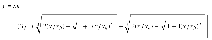
- Which corresponds to a decompression function of the desired linear-plus-cubic form:
- x=y+βy 3, where β=16/(27x h 2)
- This case is graphed in FIG. 2. When done in the digital regime, it is straightforward to implement the
compressor 110 using either of these choices. By properly selecting the parameter xh, a desired level of PAR reduction can be achieved. Selection of this parameter may require an iterative refinement process to obtain a value that gives a desired result. In this regard, for the particular signal to be compressed, the iterative refinement process would numerically determine the PAR for a given xh, and then readjust xh, repeating the calculation until the desired PAR value is reached. It is observed that compression according to these principles will tend to reduce the average power level of the signal by an amount that depends on the characteristics of the signal being compressed. Thus it may be desirable to multiply y(t) by a parameter selected to restore the average power level in the signal path to the desired level. For a DMT (discrete multitone) modulated signal, the PAR is about 14.5 dB for a clipping rate of 1 in 107. This is considered by the official specifications for ADSL (asymmetric digital subscriber line) to be an acceptable clipping rate. It is anticipated that a reduction in PAR by at least 6 dB is achievable with relatively low impact on data recovery. This has the potential to cut power consumption in line driver transistors by about a factor of 2, or more. - The multistage equalizer consists of at least two stages. Each stage takes one digital time series u 1, u2, u3, . . . as input and produces another one v1, v2, v3, . . . as output. The stages are characterized by respective functions which may depend on a number of settable parameters. In the following, the stages are, in fact, described in terms of the functions that characterize them, with the understanding that the functions are entirely descriptive of the structures of the stages, as well as their operations. FIG. 3 shows an embodiment of a function that characterizes the structure and operation of the
linear stage 140 of themultistage equalizer 137. Thelinear stage 140 is modeled as a finite-impulse response (FIR) filter characterized by the function:
- With reference to FIG. 1 and using the
function 310 shown in FIG. 3 as thefirst stage 140 of themultistage equalizer 137, the output of theADC 135 is received by thefirst stage 137 as a time sequence of digital values (the input time series 308). In thefunction 310, each successive digital value is associated with a factor, in this case, a coefficient ak, having a value that is combined (multiplied, in this case) with the digital value un+k to yield a product. The range of the index k will typically include all integer values between chosen starting and ending values k0 and k1. Note that these values may be positive, negative, or zero. The values used will depend on the dispersion and other characteristics of a particular channel. If needed, a constant parameter A may be included as indicated to correct for shifts in the level of the signal. - FIGS. 4 a, 4 b and 4 c show three embodiments of decompression functions that characterize the operation and structure of the
nonlinear stage 145 of themultistage equalizer 137. The power series function shown in FIG. 4a provides flexibility and the possibility of gaining some level of correction for intrinsic nonlinearities in the signal path in addition to achieving its primary function of decompressing the signal. This function has settable parameters that are processed as described earlier; it is given by:
- FIG. 4 b illustrates the decompression function as simply the function that is the inverse of the compression function, two examples of which were given earlier. In FIG. 4c, the decompression function is represented as a generalized expansion (other than a power series).
- FIG. 5 is a graph showing experimental results for the case in which a compressor characterized by the inverse cubic function described above achieves about a 6-dB reduction in PAR. The
upper curve 510 is the error measure as a function of channel for the compressed signal using only linear equalization to correct signal distortion. Thebottom curve 520 is for an uncompressed signal also corrected only with linear equalization. Thecurve 530 represents the compressed signal processed correctly by a multistage equalizer having a first, linear stage characterized by the linear function illustrated in FIG. 3, and a second, nonlinear stage characterized by the nonlinear function illustrated in FIG. 4a.
Claims (20)


Priority Applications (2)
| Application Number | Priority Date | Filing Date | Title |
|---|---|---|---|
| US09/968,469 US20030067990A1 (en) | 2001-10-01 | 2001-10-01 | Peak to average power ratio reduction in a digitally-modulated signal |
| US10/456,270 US20030206579A1 (en) | 2001-10-01 | 2003-06-06 | Multistage nonlinear echo-canceller for digital communication systems with or without frequency division duplexing |
Applications Claiming Priority (1)
| Application Number | Priority Date | Filing Date | Title |
|---|---|---|---|
| US09/968,469 US20030067990A1 (en) | 2001-10-01 | 2001-10-01 | Peak to average power ratio reduction in a digitally-modulated signal |
Related Child Applications (1)
| Application Number | Title | Priority Date | Filing Date |
|---|---|---|---|
| US10/456,270 Continuation-In-Part US20030206579A1 (en) | 2001-10-01 | 2003-06-06 | Multistage nonlinear echo-canceller for digital communication systems with or without frequency division duplexing |
Publications (1)
| Publication Number | Publication Date |
|---|---|
| US20030067990A1 true US20030067990A1 (en) | 2003-04-10 |
Family
ID=29216295
Family Applications (1)
| Application Number | Title | Priority Date | Filing Date |
|---|---|---|---|
| US09/968,469 Abandoned US20030067990A1 (en) | 2001-10-01 | 2001-10-01 | Peak to average power ratio reduction in a digitally-modulated signal |
Country Status (1)
| Country | Link |
|---|---|
| US (1) | US20030067990A1 (en) |
Cited By (34)
| Publication number | Priority date | Publication date | Assignee | Title |
|---|---|---|---|---|
| US20020167693A1 (en) * | 2000-12-21 | 2002-11-14 | Quellan, Inc. | Increasing data throughput in optical fiber transmission systems |
| US20020196510A1 (en) * | 2001-04-04 | 2002-12-26 | Hietala Vincent Mark | Method and system for decoding multilevel signals |
| US20030030873A1 (en) * | 2001-05-09 | 2003-02-13 | Quellan, Inc. | High-speed adjustable multilevel light modulation |
| US20030072050A1 (en) * | 2001-03-29 | 2003-04-17 | Quellan, Inc. | Multilevel pulse position modulation for efficient fiber optic communication |
| US20030156655A1 (en) * | 2002-02-15 | 2003-08-21 | Quellan, Inc. | Multi-level signal clock recovery technique |
| US20030165159A1 (en) * | 2002-01-15 | 2003-09-04 | Dietmar Straussnigg | Method for compensating for peak values during a data transmission with discrete multitone symbols and a circuit arrangement for carrying out the method |
| US20030226886A1 (en) * | 2002-06-10 | 2003-12-11 | Takashi Kakinuma | Business card information management system |
| US20040005014A1 (en) * | 2002-07-02 | 2004-01-08 | Shilpa Talwar | System and method for adjusting a power level of a transmission signal |
| US20040012433A1 (en) * | 2002-07-15 | 2004-01-22 | Quellan, Inc. | Adaptive noise filtering and equalization for optimal high speed multilevel signal decoding |
| US20040190661A1 (en) * | 2003-03-26 | 2004-09-30 | Quellan, Inc. | Method and system for equalizing communication signals |
| US20050180520A1 (en) * | 2003-12-22 | 2005-08-18 | Quellan, Inc. | Method and system for slicing a communication signal |
| US20050226353A1 (en) * | 2003-11-17 | 2005-10-13 | Quellan, Inc. | Method and system for antenna interference cancellation |
| US20060159002A1 (en) * | 2003-08-07 | 2006-07-20 | Quellan, Inc. | Method and system for crosstalk cancellation |
| US20060178157A1 (en) * | 2004-12-14 | 2006-08-10 | Quellan, Inc. | Method and system for reducing signal interference |
| US20060245345A1 (en) * | 2003-07-28 | 2006-11-02 | Matsushita Electric Industrial Co., Ltd. | Peak electric power suppressing apparatus and peak electric power suppressing method |
| WO2006114513A1 (en) * | 2005-04-28 | 2006-11-02 | France Telecom | Method for transmitting a signal modulated with high amplitude dynamics, corresponding transmitter and receiver |
| US20070060059A1 (en) * | 2004-12-14 | 2007-03-15 | Quellan, Inc. | Method and system for automatic control in an interference cancellation device |
| US20070217543A1 (en) * | 2006-03-17 | 2007-09-20 | Fujitsu Limited | Peak suppression method, peak suppression apparatus and wireless transmission apparatus |
| US20070222654A1 (en) * | 2001-03-29 | 2007-09-27 | Quellan, Inc. | Increasing data throughput in optical fiber transmission systems |
| US20070253495A1 (en) * | 2006-04-26 | 2007-11-01 | Quellan, Inc. | Method and system for reducing radiated emissions from a communications channel |
| US7292626B1 (en) * | 2001-06-04 | 2007-11-06 | National Semiconductor Corporation | Method and system for efficient quantization in DAC and ADC for discrete multitone systems |
| US7804760B2 (en) | 2003-08-07 | 2010-09-28 | Quellan, Inc. | Method and system for signal emulation |
| US7934144B2 (en) | 2002-11-12 | 2011-04-26 | Quellan, Inc. | High-speed analog-to-digital conversion with improved robustness to timing uncertainty |
| US7936835B1 (en) * | 2006-07-14 | 2011-05-03 | Pmc-Sierra, Inc. | Adaptive signal decompression |
| US20110150048A1 (en) * | 2009-12-21 | 2011-06-23 | Astrapi Corporation | Telecommunication Signaling Using Nonlinear Functions |
| WO2012142561A3 (en) * | 2011-04-15 | 2013-01-10 | Jerrold Prothero | Methods and systems for communicating |
| WO2014138527A1 (en) * | 2013-03-07 | 2014-09-12 | Astrapi Corporation | Software defined radio |
| US20160065253A1 (en) * | 2014-08-26 | 2016-03-03 | Hon Hai Precision Industry Co., Ltd. | Method for and device for reducing peak to average power ratio |
| US9461703B1 (en) * | 2004-01-20 | 2016-10-04 | Marvell International Ltd. | Interference signal compensation |
| US11184201B2 (en) | 2019-05-15 | 2021-11-23 | Astrapi Corporation | Communication devices, systems, software and methods employing symbol waveform hopping |
| US11228477B2 (en) | 2019-03-06 | 2022-01-18 | Astrapi Corporation | Devices, systems, and methods employing polynomial symbol waveforms |
| US11310090B2 (en) | 2016-05-23 | 2022-04-19 | Astrapi Corporation | Systems, transmitters, and methods employing waveform bandwidth compression to transmit information |
| US11411785B2 (en) | 2015-09-02 | 2022-08-09 | Astrapi Corporation | Spiral polynomial division multiplexing |
| US11824694B2 (en) | 2015-09-02 | 2023-11-21 | Astrapi Corporation | Systems, devices, and methods employing instantaneous spectral analysis in the transmission of signals |
Citations (43)
| Publication number | Priority date | Publication date | Assignee | Title |
|---|---|---|---|---|
| US1737830A (en) * | 1924-09-12 | 1929-12-03 | American Telephone & Telegraph | Means for and method of volume control of transmission |
| US3716807A (en) * | 1971-05-24 | 1973-02-13 | Ibm | Recursive automatic equalizer and method of operation therefore |
| US4233683A (en) * | 1978-01-31 | 1980-11-11 | Harris Corporation | Cascaded equalizer technique |
| US4288872A (en) * | 1979-05-11 | 1981-09-08 | Cselt - Centro Studi E Laboratori Telecomunicazioni S.P.A. | Equalizer for the correction of digital signals |
| US4435823A (en) * | 1980-12-29 | 1984-03-06 | Harris Corporation | Adaptive equalizer capable of linear and nonlinear weighting |
| US4792915A (en) * | 1985-05-10 | 1988-12-20 | British Telecommunications Public Limited Company | Non linear adaptive filters |
| US5049832A (en) * | 1990-04-20 | 1991-09-17 | Simon Fraser University | Amplifier linearization by adaptive predistortion |
| US5132988A (en) * | 1990-12-03 | 1992-07-21 | Board Of Trustees, Leland Stanford Jr. University | Adaptive decision feedback equalizer apparatus for processing information stored on digital storage media |
| US5226060A (en) * | 1992-01-08 | 1993-07-06 | Universal Data Systems, Inc. | Modem receiver with nonlinear equalization |
| US5317596A (en) * | 1992-12-01 | 1994-05-31 | The Board Of Trustees Of The Leland Stanford, Junior University | Method and apparatus for echo cancellation with discrete multitone modulation |
| US5343335A (en) * | 1992-08-26 | 1994-08-30 | Sony Corporation | Signal processing system having intersymbol-interference cancelling means and method of same |
| US5434883A (en) * | 1991-01-23 | 1995-07-18 | Fujitsu Limited | Adaptive equalizers |
| US5471504A (en) * | 1994-04-14 | 1995-11-28 | Computer & Communication Research Laboratories | Bilinear decision feedback equalizer |
| US5524124A (en) * | 1993-11-17 | 1996-06-04 | Signal Science, Inc. | Multiple-filter equalizer for structured digitally modulated signals |
| US5526377A (en) * | 1993-03-04 | 1996-06-11 | Adtran | Transversal filter useable in echo canceler, decision feedback equalizer applications for minimizing non-linear distortion in signals conveyed over full duplex two-wire communication link |
| US5572503A (en) * | 1993-12-15 | 1996-11-05 | Hitachi, Ltd. | Correcting non-linear distortions of optical information with a non-linear equalizer |
| US5598127A (en) * | 1992-12-23 | 1997-01-28 | Italtel S.P.A. | Procedure and circuit for adaptive compensation of the gain distortions of a microwave amplifier with linearizer |
| US5623513A (en) * | 1993-12-13 | 1997-04-22 | Amati Communications Corporation | Mitigating clipping and quantization effects in digital transmission systems |
| US5627885A (en) * | 1994-02-14 | 1997-05-06 | Brooktree Corporation | System for, and method of, transmitting and receiving through telephone lines signals representing data |
| US5651028A (en) * | 1995-05-09 | 1997-07-22 | Unisys Corporation | Data transmission system with a low peak-to-average power ratio based on distorting frequently occuring signals |
| US5668806A (en) * | 1994-07-21 | 1997-09-16 | Canon Kabushiki Kaisha | Spread spectrum communication apparatus |
| US5717716A (en) * | 1995-03-31 | 1998-02-10 | Intel Corporation | Quasi-adaptive analog equalization method and apparatus |
| US5740206A (en) * | 1991-07-19 | 1998-04-14 | Interdigital Technology Corporation | Adaptive nonlinear equalizer for digital FM signals |
| US5751769A (en) * | 1996-10-22 | 1998-05-12 | Lockheed Martin Aerospace Corp. | Programmable digital linear and nonlinear transversal equalizer |
| US5793797A (en) * | 1995-05-09 | 1998-08-11 | Unisys Corporation | Data transmisson system with a low peak-to-average power ratio based on distorting small amplitude signals |
| US5838732A (en) * | 1994-10-31 | 1998-11-17 | Airnet Communications Corp. | Reducing peak-to-average variance of a composite transmitted signal generated by a digital combiner via carrier phase offset |
| US5995539A (en) * | 1993-03-17 | 1999-11-30 | Miller; William J. | Method and apparatus for signal transmission and reception |
| US6052349A (en) * | 1996-09-30 | 2000-04-18 | Kabushiki Kaisha Toshiba | Waveform equalizer and memory device having a waveform equalizer |
| US6064692A (en) * | 1997-06-20 | 2000-05-16 | Amati Communications Corporation | Protocol for transceiver initialization |
| US6128350A (en) * | 1999-08-24 | 2000-10-03 | Usa Digital Radio, Inc. | Method and apparatus for reducing peak to average power ratio in digital broadcasting systems |
| US6147984A (en) * | 1999-04-14 | 2000-11-14 | Motorola, Inc. | Method and apparatus for peak limiting in a modulator |
| US6188714B1 (en) * | 1998-12-29 | 2001-02-13 | Texas Instruments Incorporated | Parallel M-sequence generator circuit |
| US6198416B1 (en) * | 1999-04-16 | 2001-03-06 | Scott R. Velazquez | Linearity error compensator |
| US6236864B1 (en) * | 1998-11-27 | 2001-05-22 | Nortel Networks Limited | CDMA transmit peak power reduction |
| US6240141B1 (en) * | 1998-05-09 | 2001-05-29 | Centillium Communications, Inc. | Lower-complexity peak-to-average reduction using intermediate-result subset sign-inversion for DSL |
| US20010022777A1 (en) * | 1999-12-03 | 2001-09-20 | Catena Networks, Inc. | Peak to average power ratio reduction in communication systems |
| US6294956B1 (en) * | 1999-11-19 | 2001-09-25 | Lucent Technologies Inc. | System and method for producing amplified signal(s) or version(s) thereof |
| US6314146B1 (en) * | 1998-06-05 | 2001-11-06 | The Board Of Trustees Of The Leland Stanford Junior University | Peak to average power ratio reduction |
| US6424275B1 (en) * | 2001-01-18 | 2002-07-23 | Scott R. Velazquez | Linearity error compensator |
| US20030063663A1 (en) * | 2001-10-01 | 2003-04-03 | Bryant Paul Henry | Multistage equalizer that corrects for linear and nonlinear distortion in a digitally-modulated signal |
| US6587514B1 (en) * | 1999-07-13 | 2003-07-01 | Pmc-Sierra, Inc. | Digital predistortion methods for wideband amplifiers |
| US6597746B1 (en) * | 1999-02-18 | 2003-07-22 | Globespanvirata, Inc. | System and method for peak to average power ratio reduction |
| US6650698B1 (en) * | 1999-09-29 | 2003-11-18 | Conexant Systems, Inc. | Non-linear equalization for the upstream data connection of 56K PCM modems |
-
2001
- 2001-10-01 US US09/968,469 patent/US20030067990A1/en not_active Abandoned
Patent Citations (43)
| Publication number | Priority date | Publication date | Assignee | Title |
|---|---|---|---|---|
| US1737830A (en) * | 1924-09-12 | 1929-12-03 | American Telephone & Telegraph | Means for and method of volume control of transmission |
| US3716807A (en) * | 1971-05-24 | 1973-02-13 | Ibm | Recursive automatic equalizer and method of operation therefore |
| US4233683A (en) * | 1978-01-31 | 1980-11-11 | Harris Corporation | Cascaded equalizer technique |
| US4288872A (en) * | 1979-05-11 | 1981-09-08 | Cselt - Centro Studi E Laboratori Telecomunicazioni S.P.A. | Equalizer for the correction of digital signals |
| US4435823A (en) * | 1980-12-29 | 1984-03-06 | Harris Corporation | Adaptive equalizer capable of linear and nonlinear weighting |
| US4792915A (en) * | 1985-05-10 | 1988-12-20 | British Telecommunications Public Limited Company | Non linear adaptive filters |
| US5049832A (en) * | 1990-04-20 | 1991-09-17 | Simon Fraser University | Amplifier linearization by adaptive predistortion |
| US5132988A (en) * | 1990-12-03 | 1992-07-21 | Board Of Trustees, Leland Stanford Jr. University | Adaptive decision feedback equalizer apparatus for processing information stored on digital storage media |
| US5434883A (en) * | 1991-01-23 | 1995-07-18 | Fujitsu Limited | Adaptive equalizers |
| US5740206A (en) * | 1991-07-19 | 1998-04-14 | Interdigital Technology Corporation | Adaptive nonlinear equalizer for digital FM signals |
| US5226060A (en) * | 1992-01-08 | 1993-07-06 | Universal Data Systems, Inc. | Modem receiver with nonlinear equalization |
| US5343335A (en) * | 1992-08-26 | 1994-08-30 | Sony Corporation | Signal processing system having intersymbol-interference cancelling means and method of same |
| US5317596A (en) * | 1992-12-01 | 1994-05-31 | The Board Of Trustees Of The Leland Stanford, Junior University | Method and apparatus for echo cancellation with discrete multitone modulation |
| US5598127A (en) * | 1992-12-23 | 1997-01-28 | Italtel S.P.A. | Procedure and circuit for adaptive compensation of the gain distortions of a microwave amplifier with linearizer |
| US5526377A (en) * | 1993-03-04 | 1996-06-11 | Adtran | Transversal filter useable in echo canceler, decision feedback equalizer applications for minimizing non-linear distortion in signals conveyed over full duplex two-wire communication link |
| US5995539A (en) * | 1993-03-17 | 1999-11-30 | Miller; William J. | Method and apparatus for signal transmission and reception |
| US5524124A (en) * | 1993-11-17 | 1996-06-04 | Signal Science, Inc. | Multiple-filter equalizer for structured digitally modulated signals |
| US5623513A (en) * | 1993-12-13 | 1997-04-22 | Amati Communications Corporation | Mitigating clipping and quantization effects in digital transmission systems |
| US5572503A (en) * | 1993-12-15 | 1996-11-05 | Hitachi, Ltd. | Correcting non-linear distortions of optical information with a non-linear equalizer |
| US5627885A (en) * | 1994-02-14 | 1997-05-06 | Brooktree Corporation | System for, and method of, transmitting and receiving through telephone lines signals representing data |
| US5471504A (en) * | 1994-04-14 | 1995-11-28 | Computer & Communication Research Laboratories | Bilinear decision feedback equalizer |
| US5668806A (en) * | 1994-07-21 | 1997-09-16 | Canon Kabushiki Kaisha | Spread spectrum communication apparatus |
| US5838732A (en) * | 1994-10-31 | 1998-11-17 | Airnet Communications Corp. | Reducing peak-to-average variance of a composite transmitted signal generated by a digital combiner via carrier phase offset |
| US5717716A (en) * | 1995-03-31 | 1998-02-10 | Intel Corporation | Quasi-adaptive analog equalization method and apparatus |
| US5793797A (en) * | 1995-05-09 | 1998-08-11 | Unisys Corporation | Data transmisson system with a low peak-to-average power ratio based on distorting small amplitude signals |
| US5651028A (en) * | 1995-05-09 | 1997-07-22 | Unisys Corporation | Data transmission system with a low peak-to-average power ratio based on distorting frequently occuring signals |
| US6052349A (en) * | 1996-09-30 | 2000-04-18 | Kabushiki Kaisha Toshiba | Waveform equalizer and memory device having a waveform equalizer |
| US5751769A (en) * | 1996-10-22 | 1998-05-12 | Lockheed Martin Aerospace Corp. | Programmable digital linear and nonlinear transversal equalizer |
| US6064692A (en) * | 1997-06-20 | 2000-05-16 | Amati Communications Corporation | Protocol for transceiver initialization |
| US6240141B1 (en) * | 1998-05-09 | 2001-05-29 | Centillium Communications, Inc. | Lower-complexity peak-to-average reduction using intermediate-result subset sign-inversion for DSL |
| US6314146B1 (en) * | 1998-06-05 | 2001-11-06 | The Board Of Trustees Of The Leland Stanford Junior University | Peak to average power ratio reduction |
| US6236864B1 (en) * | 1998-11-27 | 2001-05-22 | Nortel Networks Limited | CDMA transmit peak power reduction |
| US6188714B1 (en) * | 1998-12-29 | 2001-02-13 | Texas Instruments Incorporated | Parallel M-sequence generator circuit |
| US6597746B1 (en) * | 1999-02-18 | 2003-07-22 | Globespanvirata, Inc. | System and method for peak to average power ratio reduction |
| US6147984A (en) * | 1999-04-14 | 2000-11-14 | Motorola, Inc. | Method and apparatus for peak limiting in a modulator |
| US6198416B1 (en) * | 1999-04-16 | 2001-03-06 | Scott R. Velazquez | Linearity error compensator |
| US6587514B1 (en) * | 1999-07-13 | 2003-07-01 | Pmc-Sierra, Inc. | Digital predistortion methods for wideband amplifiers |
| US6128350A (en) * | 1999-08-24 | 2000-10-03 | Usa Digital Radio, Inc. | Method and apparatus for reducing peak to average power ratio in digital broadcasting systems |
| US6650698B1 (en) * | 1999-09-29 | 2003-11-18 | Conexant Systems, Inc. | Non-linear equalization for the upstream data connection of 56K PCM modems |
| US6294956B1 (en) * | 1999-11-19 | 2001-09-25 | Lucent Technologies Inc. | System and method for producing amplified signal(s) or version(s) thereof |
| US20010022777A1 (en) * | 1999-12-03 | 2001-09-20 | Catena Networks, Inc. | Peak to average power ratio reduction in communication systems |
| US6424275B1 (en) * | 2001-01-18 | 2002-07-23 | Scott R. Velazquez | Linearity error compensator |
| US20030063663A1 (en) * | 2001-10-01 | 2003-04-03 | Bryant Paul Henry | Multistage equalizer that corrects for linear and nonlinear distortion in a digitally-modulated signal |
Cited By (71)
| Publication number | Priority date | Publication date | Assignee | Title |
|---|---|---|---|---|
| US20020167693A1 (en) * | 2000-12-21 | 2002-11-14 | Quellan, Inc. | Increasing data throughput in optical fiber transmission systems |
| US20030072050A1 (en) * | 2001-03-29 | 2003-04-17 | Quellan, Inc. | Multilevel pulse position modulation for efficient fiber optic communication |
| US20070222654A1 (en) * | 2001-03-29 | 2007-09-27 | Quellan, Inc. | Increasing data throughput in optical fiber transmission systems |
| US20020196510A1 (en) * | 2001-04-04 | 2002-12-26 | Hietala Vincent Mark | Method and system for decoding multilevel signals |
| US20070171998A1 (en) * | 2001-04-04 | 2007-07-26 | Quellan, Inc. | Method and system for decoding multilevel signals |
| US20030030873A1 (en) * | 2001-05-09 | 2003-02-13 | Quellan, Inc. | High-speed adjustable multilevel light modulation |
| US7292626B1 (en) * | 2001-06-04 | 2007-11-06 | National Semiconductor Corporation | Method and system for efficient quantization in DAC and ADC for discrete multitone systems |
| US20030165159A1 (en) * | 2002-01-15 | 2003-09-04 | Dietmar Straussnigg | Method for compensating for peak values during a data transmission with discrete multitone symbols and a circuit arrangement for carrying out the method |
| US7359443B2 (en) * | 2002-01-15 | 2008-04-15 | Infineon Technologies Ag | Method for compensating for peak values during a data transmission with discrete multitone symbols and a circuit arrangement for carrying out the method |
| US20030156655A1 (en) * | 2002-02-15 | 2003-08-21 | Quellan, Inc. | Multi-level signal clock recovery technique |
| US20030226886A1 (en) * | 2002-06-10 | 2003-12-11 | Takashi Kakinuma | Business card information management system |
| US6891902B2 (en) * | 2002-07-02 | 2005-05-10 | Intel Corporation | System and method for adjusting a power level of a transmission signal |
| US20040005014A1 (en) * | 2002-07-02 | 2004-01-08 | Shilpa Talwar | System and method for adjusting a power level of a transmission signal |
| US7035361B2 (en) * | 2002-07-15 | 2006-04-25 | Quellan, Inc. | Adaptive noise filtering and equalization for optimal high speed multilevel signal decoding |
| US8311168B2 (en) | 2002-07-15 | 2012-11-13 | Quellan, Inc. | Adaptive noise filtering and equalization for optimal high speed multilevel signal decoding |
| US20100040180A1 (en) * | 2002-07-15 | 2010-02-18 | Andrew Joo Kim | Adaptive noise filtering and equalization for optimal high speed multilevel signal decoding |
| US20060239390A1 (en) * | 2002-07-15 | 2006-10-26 | Quellan, Inc. | Adaptive noise filtering and equalization for optimal high speed multilevel signal decoding |
| US7573966B2 (en) * | 2002-07-15 | 2009-08-11 | Quellan, Inc. | Adaptive noise filtering and equalization for optimal high speed multilevel signal decoding |
| US20040012433A1 (en) * | 2002-07-15 | 2004-01-22 | Quellan, Inc. | Adaptive noise filtering and equalization for optimal high speed multilevel signal decoding |
| US7934144B2 (en) | 2002-11-12 | 2011-04-26 | Quellan, Inc. | High-speed analog-to-digital conversion with improved robustness to timing uncertainty |
| US20040190661A1 (en) * | 2003-03-26 | 2004-09-30 | Quellan, Inc. | Method and system for equalizing communication signals |
| US20060245345A1 (en) * | 2003-07-28 | 2006-11-02 | Matsushita Electric Industrial Co., Ltd. | Peak electric power suppressing apparatus and peak electric power suppressing method |
| US20110069604A1 (en) * | 2003-08-07 | 2011-03-24 | Quellan, Inc. | Method and System for Signal Emulation |
| US7804760B2 (en) | 2003-08-07 | 2010-09-28 | Quellan, Inc. | Method and system for signal emulation |
| US8605566B2 (en) | 2003-08-07 | 2013-12-10 | Quellan, Inc. | Method and system for signal emulation |
| US8068406B2 (en) | 2003-08-07 | 2011-11-29 | Quellan, Inc. | Method and system for crosstalk cancellation |
| US20100039923A1 (en) * | 2003-08-07 | 2010-02-18 | Quellan, Inc. | Method and System for Crosstalk Cancellation |
| US20060159002A1 (en) * | 2003-08-07 | 2006-07-20 | Quellan, Inc. | Method and system for crosstalk cancellation |
| US20050226353A1 (en) * | 2003-11-17 | 2005-10-13 | Quellan, Inc. | Method and system for antenna interference cancellation |
| US7729431B2 (en) | 2003-11-17 | 2010-06-01 | Quellan, Inc. | Method and system for antenna interference cancellation |
| US8576939B2 (en) | 2003-12-22 | 2013-11-05 | Quellan, Inc. | Method and system for slicing a communication signal |
| US20050180520A1 (en) * | 2003-12-22 | 2005-08-18 | Quellan, Inc. | Method and system for slicing a communication signal |
| US20100027709A1 (en) * | 2003-12-22 | 2010-02-04 | Quellan, Inc. | Method And System For Slicing A Communication Signal |
| US9461703B1 (en) * | 2004-01-20 | 2016-10-04 | Marvell International Ltd. | Interference signal compensation |
| US8135350B2 (en) | 2004-12-14 | 2012-03-13 | Quellan, Inc. | System for reducing signal interference |
| US7725079B2 (en) | 2004-12-14 | 2010-05-25 | Quellan, Inc. | Method and system for automatic control in an interference cancellation device |
| US20060178157A1 (en) * | 2004-12-14 | 2006-08-10 | Quellan, Inc. | Method and system for reducing signal interference |
| US20070060059A1 (en) * | 2004-12-14 | 2007-03-15 | Quellan, Inc. | Method and system for automatic control in an interference cancellation device |
| US8503940B2 (en) | 2004-12-14 | 2013-08-06 | Quellan, Inc. | Reducing signal interference |
| US20090170438A1 (en) * | 2004-12-14 | 2009-07-02 | Quellan, Inc. | Method and system for reducing signal interference |
| US8005430B2 (en) | 2004-12-14 | 2011-08-23 | Quellan Inc. | Method and system for reducing signal interference |
| WO2006114513A1 (en) * | 2005-04-28 | 2006-11-02 | France Telecom | Method for transmitting a signal modulated with high amplitude dynamics, corresponding transmitter and receiver |
| US7839949B2 (en) * | 2006-03-17 | 2010-11-23 | Fujitsu Limited | Peak suppression method, peak suppression apparatus and wireless transmission apparatus |
| US20070217543A1 (en) * | 2006-03-17 | 2007-09-20 | Fujitsu Limited | Peak suppression method, peak suppression apparatus and wireless transmission apparatus |
| US9252983B2 (en) | 2006-04-26 | 2016-02-02 | Intersil Americas LLC | Method and system for reducing radiated emissions from a communications channel |
| US20070253495A1 (en) * | 2006-04-26 | 2007-11-01 | Quellan, Inc. | Method and system for reducing radiated emissions from a communications channel |
| US8396149B1 (en) | 2006-07-14 | 2013-03-12 | Pmc-Sierra, Inc. | Adaptive signal decompression |
| US7936835B1 (en) * | 2006-07-14 | 2011-05-03 | Pmc-Sierra, Inc. | Adaptive signal decompression |
| US8687723B1 (en) * | 2006-07-14 | 2014-04-01 | Pmc-Sierra, Inc. | Adaptive signal decompression |
| US8472534B2 (en) | 2009-12-21 | 2013-06-25 | Astrapi Corporation | Telecommunication signaling using nonlinear functions |
| US20110150048A1 (en) * | 2009-12-21 | 2011-06-23 | Astrapi Corporation | Telecommunication Signaling Using Nonlinear Functions |
| WO2011084280A1 (en) * | 2009-12-21 | 2011-07-14 | Astrapi Corporation | Telecommunication signaling using nonlinear functions |
| US9602324B2 (en) | 2009-12-21 | 2017-03-21 | Astrapi Corporation | Telecommunication signaling using nonlinear functions |
| US9258168B2 (en) | 2009-12-21 | 2016-02-09 | Astrapi Corporation | Telecommunication signaling using nonlinear functions |
| US8948278B2 (en) | 2009-12-21 | 2015-02-03 | Astrapi Corporation | Telecommunication signaling using nonlinear functions |
| JP2014512147A (en) * | 2011-04-15 | 2014-05-19 | アストラピ コーポレーション | Communication method and apparatus |
| US11848812B2 (en) | 2011-04-15 | 2023-12-19 | Astrapi Corporation | Methods and systems for communicating |
| US8861327B2 (en) | 2011-04-15 | 2014-10-14 | Astrapi Corporation | Methods and systems for communicating |
| US11240088B2 (en) | 2011-04-15 | 2022-02-01 | Astrapi Corporation | Methods and systems for transmitting and receiving data using non-periodic functions |
| WO2012142561A3 (en) * | 2011-04-15 | 2013-01-10 | Jerrold Prothero | Methods and systems for communicating |
| WO2014138527A1 (en) * | 2013-03-07 | 2014-09-12 | Astrapi Corporation | Software defined radio |
| US8995546B2 (en) | 2013-03-07 | 2015-03-31 | Astrapi Corporation | Software defined radio |
| US9647702B2 (en) * | 2014-08-26 | 2017-05-09 | Hon Hai Precision Industry Co., Ltd. | Method for and device for reducing peak to average power ratio |
| US20160065253A1 (en) * | 2014-08-26 | 2016-03-03 | Hon Hai Precision Industry Co., Ltd. | Method for and device for reducing peak to average power ratio |
| US11411785B2 (en) | 2015-09-02 | 2022-08-09 | Astrapi Corporation | Spiral polynomial division multiplexing |
| US11824694B2 (en) | 2015-09-02 | 2023-11-21 | Astrapi Corporation | Systems, devices, and methods employing instantaneous spectral analysis in the transmission of signals |
| US11310090B2 (en) | 2016-05-23 | 2022-04-19 | Astrapi Corporation | Systems, transmitters, and methods employing waveform bandwidth compression to transmit information |
| US11228477B2 (en) | 2019-03-06 | 2022-01-18 | Astrapi Corporation | Devices, systems, and methods employing polynomial symbol waveforms |
| US11729041B2 (en) | 2019-03-06 | 2023-08-15 | Astrapi Corporation | Devices, systems, and methods employing polynomial symbol waveforms |
| US11184201B2 (en) | 2019-05-15 | 2021-11-23 | Astrapi Corporation | Communication devices, systems, software and methods employing symbol waveform hopping |
| US11582075B2 (en) | 2019-05-15 | 2023-02-14 | Astrapi Corporation | Communication devices, systems, software and methods employing symbol waveform hopping |
Similar Documents
| Publication | Publication Date | Title |
|---|---|---|
| US20030067990A1 (en) | Peak to average power ratio reduction in a digitally-modulated signal | |
| Armstrong | New OFDM peak-to-average power reduction scheme | |
| US6985533B2 (en) | Method and apparatus for reducing peak to average power ratio in a multi-carrier modulation communication system | |
| JP4261367B2 (en) | Method and apparatus for improving transmitter performance using baseband conversion | |
| US6252909B1 (en) | Multi-carrier transmission system utilizing channels of different bandwidth | |
| US5696794A (en) | Method and apparatus for conditioning digitally modulated signals using channel symbol adjustment | |
| EP2296266A1 (en) | Multi-carrier amplifier linearization system and method | |
| JPH08501195A (en) | Digital signal transmission system using frequency division multiplexing. | |
| US20030063663A1 (en) | Multistage equalizer that corrects for linear and nonlinear distortion in a digitally-modulated signal | |
| US20020176509A1 (en) | Discrete multitone modulation with reduced peak-to-average ratio using unloaded subchannels | |
| US20070183534A1 (en) | Phasor fragmentation circuitry and method for processing modulated signals having non-constant envelopes | |
| US20030031268A1 (en) | Computational circuits and methods for processing modulated signals having non-constant envelopes | |
| US20030206579A1 (en) | Multistage nonlinear echo-canceller for digital communication systems with or without frequency division duplexing | |
| EP1039714A2 (en) | Block code for multicarrier transmission | |
| US20080285432A1 (en) | Method for Generating Candidates used in Turbo Coded Orthogonal Frequency-Division Multiplexing System with Selective Mapping Technique | |
| CN1194749A (en) | Filter for multicarrier communication system and method for peak power control therein | |
| Aggarwal et al. | Minimizing the peak-to-average power ratio of OFDM signals via convex optimization | |
| Tellambura | A coding technique for reducing peak-to-average power ratio in OFDM | |
| US20030156657A1 (en) | Transmitter for transmitting signals over radio channels and mehtod for transmitting signals over radio channels | |
| US20030157905A1 (en) | Transmitter and associated method for reducing the adjacent channel power during wireless communications | |
| CN105684338A (en) | Crest factor reduction of inter-band carrier aggregated signals | |
| EP1179255B1 (en) | Transmitter for transmitting signals over radio channels and method for transmitting signals over radio channels | |
| WO2004080022A1 (en) | Peak to average power ratio reduction in a digitally-modulated signal | |
| EP1473837A1 (en) | Method and apparatus for reduced power consumption ADC/DAC conversion | |
| US20040232983A1 (en) | Method and apparatus for low intermodulation distortion amplification in selected bands |
Legal Events
| Date | Code | Title | Description |
|---|---|---|---|
| AS | Assignment |
Owner name: RECORDING PHYSCIS, INCORPORATED, CALIFORNIA Free format text: ASSIGNMENT OF ASSIGNORS INTEREST;ASSIGNOR:BRYANT, PAUL HENRY;REEL/FRAME:012480/0410 Effective date: 20010928 |
|
| AS | Assignment |
Owner name: CHAOS TELECOM, INC., CALIFORNIA Free format text: MORTGAGE;ASSIGNOR:RECORDING PHYSICS,INC.;REEL/FRAME:012664/0668 Effective date: 20010928 |
|
| AS | Assignment |
Owner name: XR VENTURES, LLC, MICHIGAN Free format text: SECURITY AGREEMENT;ASSIGNOR:CHAOS TELECOM, INC.;REEL/FRAME:012824/0273 Effective date: 20010913 |
|
| AS | Assignment |
Owner name: XR VENTURES, LLC, MICHIGAN Free format text: RELEASE BY SECURED PARTY;ASSIGNOR:CHAOS TELECOM, INC.;REEL/FRAME:013394/0134 Effective date: 20021007 |
|
| STCB | Information on status: application discontinuation |
Free format text: ABANDONED -- FAILURE TO RESPOND TO AN OFFICE ACTION |