US20030076777A1 - Apparatus and methods for providing efficient space-time structures for preambles, pilots and data for multi-input, multi-output communications systems - Google Patents
Apparatus and methods for providing efficient space-time structures for preambles, pilots and data for multi-input, multi-output communications systems Download PDFInfo
- Publication number
- US20030076777A1 US20030076777A1 US10/245,090 US24509002A US2003076777A1 US 20030076777 A1 US20030076777 A1 US 20030076777A1 US 24509002 A US24509002 A US 24509002A US 2003076777 A1 US2003076777 A1 US 2003076777A1
- Authority
- US
- United States
- Prior art keywords
- space
- time
- symbols
- data
- structures
- Prior art date
- Legal status (The legal status is an assumption and is not a legal conclusion. Google has not performed a legal analysis and makes no representation as to the accuracy of the status listed.)
- Granted
Links
Images


Classifications
-
- H—ELECTRICITY
- H04—ELECTRIC COMMUNICATION TECHNIQUE
- H04L—TRANSMISSION OF DIGITAL INFORMATION, e.g. TELEGRAPHIC COMMUNICATION
- H04L25/00—Baseband systems
- H04L25/02—Details ; arrangements for supplying electrical power along data transmission lines
- H04L25/0202—Channel estimation
- H04L25/0224—Channel estimation using sounding signals
- H04L25/0226—Channel estimation using sounding signals sounding signals per se
-
- H—ELECTRICITY
- H04—ELECTRIC COMMUNICATION TECHNIQUE
- H04B—TRANSMISSION
- H04B7/00—Radio transmission systems, i.e. using radiation field
- H04B7/02—Diversity systems; Multi-antenna system, i.e. transmission or reception using multiple antennas
- H04B7/04—Diversity systems; Multi-antenna system, i.e. transmission or reception using multiple antennas using two or more spaced independent antennas
- H04B7/06—Diversity systems; Multi-antenna system, i.e. transmission or reception using multiple antennas using two or more spaced independent antennas at the transmitting station
- H04B7/0613—Diversity systems; Multi-antenna system, i.e. transmission or reception using multiple antennas using two or more spaced independent antennas at the transmitting station using simultaneous transmission
- H04B7/0667—Diversity systems; Multi-antenna system, i.e. transmission or reception using multiple antennas using two or more spaced independent antennas at the transmitting station using simultaneous transmission of delayed versions of same signal
- H04B7/0669—Diversity systems; Multi-antenna system, i.e. transmission or reception using multiple antennas using two or more spaced independent antennas at the transmitting station using simultaneous transmission of delayed versions of same signal using different channel coding between antennas
-
- H—ELECTRICITY
- H04—ELECTRIC COMMUNICATION TECHNIQUE
- H04L—TRANSMISSION OF DIGITAL INFORMATION, e.g. TELEGRAPHIC COMMUNICATION
- H04L1/00—Arrangements for detecting or preventing errors in the information received
- H04L1/02—Arrangements for detecting or preventing errors in the information received by diversity reception
- H04L1/06—Arrangements for detecting or preventing errors in the information received by diversity reception using space diversity
-
- H—ELECTRICITY
- H04—ELECTRIC COMMUNICATION TECHNIQUE
- H04L—TRANSMISSION OF DIGITAL INFORMATION, e.g. TELEGRAPHIC COMMUNICATION
- H04L27/00—Modulated-carrier systems
- H04L27/26—Systems using multi-frequency codes
- H04L27/2601—Multicarrier modulation systems
- H04L27/2602—Signal structure
- H04L27/261—Details of reference signals
- H04L27/2613—Structure of the reference signals
-
- H—ELECTRICITY
- H04—ELECTRIC COMMUNICATION TECHNIQUE
- H04L—TRANSMISSION OF DIGITAL INFORMATION, e.g. TELEGRAPHIC COMMUNICATION
- H04L27/00—Modulated-carrier systems
- H04L27/0014—Carrier regulation
- H04L2027/0083—Signalling arrangements
- H04L2027/0089—In-band signals
- H04L2027/0093—Intermittant signals
- H04L2027/0095—Intermittant signals in a preamble or similar structure
-
- H—ELECTRICITY
- H04—ELECTRIC COMMUNICATION TECHNIQUE
- H04L—TRANSMISSION OF DIGITAL INFORMATION, e.g. TELEGRAPHIC COMMUNICATION
- H04L27/00—Modulated-carrier systems
- H04L27/26—Systems using multi-frequency codes
- H04L27/2601—Multicarrier modulation systems
- H04L27/2602—Signal structure
- H04L27/261—Details of reference signals
- H04L27/2613—Structure of the reference signals
- H04L27/26134—Pilot insertion in the transmitter chain, e.g. pilot overlapping with data, insertion in time or frequency domain
Definitions
- the present invention is generally related to communications systems and, more particularly, to Multi-Input, Multi-Output (MIMO) communications systems.
- MIMO Multi-Input, Multi-Output
- signals are typically transmitted over a common path (i.e., a channel) by multiple antennas.
- the signals are typically pre-processed to avoid interference from other signals in the common channel.
- One such technique known as Space-Time Processing (STP), processes and combines “preambles” and “data symbols” into “space-time signal structures.”
- Wireless communications systems typically transmit data or information (e.g., voice, video, audio, text, etc.) as formatted signals, known as data symbols (or information symbols), which are typically organized into groups, known as data frames (or information frames).
- Training symbols are another type of symbol, which are typically added as prefixes to data symbols (e.g., at the beginning of data frames), to enable training (i.e., synchronization) of the data symbols between the transmitters and receivers of a MIMO communications system.
- These training symbol prefixes can be referred to as preambles or preamble structures.
- the combination of the preambles and data symbols can be referred to as space-time signal structures. Space-time structures may also be constructed using STP for preambles and data symbols individually.
- pilot structures are space-time structures that are also constructed by STP and have the same structure as preambles, although they are periodically arranged within groups of data symbols for different purposes.
- space-time signal structures make it possible to recover the data symbols from them through post-processing by a receiver, for example.
- formation and processing of space-time signal structures in a wireless communications system may provide increased strength (i.e., gain) in the recovered signal, which typically enhances the performance of the communications system.
- FDM Frequency Division Multiplexing
- OFDM Orthogonal Frequency Division Multiplexing
- MIMO OFDM systems provides the added capability of increased capacity to transmit and receive information using, generally, the same amount of bandwidth (i.e., transmission line capacity) as used in SISO OFDM systems.
- MIMO OFDM communications systems also offer improved performance to overcome some of the difficulties experienced in other FDM communications systems, such as performance degradation due to multiple versions of a transmitted signal being received over various transmission paths (i.e., multi-path channel interference).
- synchronization of data symbols is typically required in both time and frequency.
- Estimation of noise variance and channel parameters is also typically required.
- efficient preamble structures and pilot structures for use in wireless communications systems should provide both synchronization and parameter estimation.
- efficient preamble structures and pilot structures should possess a low peak-to-average power ratio (PAPR) (i.e., at or approaching unity) to facilitate efficient system operation.
- PAPR peak-to-average power ratio
- existing preamble structures and pilot structures have shortcomings in their capability to provide the foregoing functions of time and frequency synchronization, estimation of noise variance and channel parameters, and low PAPR.
- the IEEE Standard 802.11a preamble structure includes a short sequence, which provides time synchronization and coarse frequency offset estimation, followed by a long sequence, which provides fine frequency and channel estimation.
- this preamble has direct application to SISO communications systems, it is not directly applicable to MIMO communications systems to provide the above mentioned functions, without the need for significant modifications.
- Existing techniques for space-time processing of preamble symbols, pilot symbols, and data symbols into space-time structures also have shortcomings in their applications to MIMO communications systems.
- existing space-time structures i.e., preamble, pilot, or data
- MIMO communications systems may be required that employ other numbers of transmit antennas to satisfy various applications.
- existing space-time structures do not support the “full diversity” performance of MIMO communications systems. That is, existing space-time structures do not support the optimal signal transmission performance that MIMO communications systems can provide.
- a MIMO communications system that employs four transmit antennas can provide a full diversity signal transmission performance of four space-time structures over four time periods.
- typical existing space-time structures are limited to support a signal transmission performance of no better than three space-time structures over four time periods in a four-antenna MIMO system.
- the present invention provides an apparatus and methods for providing efficient space-time structures for preambles, pilots and data for multi-input, multi-output (MIMO) communications systems.
- MIMO multi-input, multi-output
- one embodiment of the present invention includes providing a computer program that includes logic configured to provide an initial structure.
- the computer program further includes logic configured to verify that the rows of the initial structure are linearly independent and logic configured to apply an orthonormalization procedure to the initial structure to obtain a space-time structure.
- the present invention can also be viewed as providing methods for providing efficient space-time structures for preambles, pilots and data for MIMO communications systems.
- one embodiment of such a method can be broadly summarized by the following: providing an initial structure, verifying that the rows of the initial structure are linearly independent, and applying an orthonormalization procedure to the initial structure to obtain a space-time structure.
- Another embodiment of a method of the present invention can be broadly described by the following: selecting a data structure, verifying that the data structure is a unitary transmission matrix, and applying the data structure as a space-time preamble structure.
- FIG. 1 is a block diagram of an exemplary Multi-Input, Multi-Output (MIMO) communications system.
- MIMO Multi-Input, Multi-Output
- FIG. 7 is a flow chart illustrating an exemplary method to determine an initial structure for use in the method described with respect to FIG. 6.
- FIG. 8 is a flow chart illustrating an alternative method for providing efficient space-time structures for preambles, pilots and data that may be implemented in a MIMO communications system, such as the system depicted in FIG. 1.
- FIG. 1 shows a block diagram of an exemplary Multi-Input, Multi-Output (MIMO) communications system 6 .
- MIMO Multi-Input, Multi-Output
- the exemplary MIMO communications system 6 and its sub-components will be described hereinafter to facilitate the description of the present invention.
- the exemplary MIMO communications system 6 may be implemented as a wireless system for the transmission and reception of data across a wireless channel 19 , as depicted in FIG. 1.
- the MIMO communications system 6 may be implemented as part of a wireless Local Area Network (LAN) or Metropolitan Area Network (MAN) system, a cellular telephone system, or another type of radio or microwave frequency system incorporating one-way or two-way communications over a range of distances.
- LAN Local Area Network
- MAN Metropolitan Area Network
- the MIMO communications system 6 may transmit and receive signals at various frequencies.
- the MIMO communications system 6 may transmit and receive signals in a frequency range from 2 to 11 GHz, such as in the unlicensed 5.8 GHz band, using a bandwidth of about 3 to 6 MHz.
- the MIMO communications system 6 may employ various signal modulation and demodulation techniques, such as Single-Carrier Frequency Domain Equalization (SCFDE) or Orthogonal Frequency Division Multiplexing (OFDM), for example.
- SCFDE Single-Carrier Frequency Domain Equalization
- OFDM Orthogonal Frequency Division Multiplexing
- the MIMO communications system 6 may also be implemented as part of a communications system (not shown) that includes an array of sub-channel communications links, which convey one or more signals transmitted by one or more transmitting elements to one or more receiving elements.
- the sub-channel communications links may include wires (e.g., in a wiring harness) or other forms of tangible transmission medium that span between a data source and a receiver within the communications system.
- the MIMO communications system 6 includes a transmitter 8 and a receiver 10 .
- the transmitter 8 typically transmits signals across a channel 19 to the receiver 10 .
- the transmitter 8 typically includes several components.
- the transmitter 8 includes an encoder 14 .
- the encoder 14 typically encodes data and/or other types of signals received, for example, from a data source 12 . Such signals may alternatively be referred to collectively hereinafter as “data,” “signals,” or “data signals.”
- the data source 12 may be a device, system, etc. that outputs such signals.
- the encoder 14 may also perform functions such as employing a channel code on data for transmission and forming sequence structures by space-time processing (STP) techniques.
- STP space-time processing
- the encoder 14 may separate the received signals onto one or more signal paths 15 , included in the transmitter 8 , which will be referred to hereinafter as transmit diversity branches (TDBs) 15 .
- TDBs transmit diversity branches
- Each TDB 15 may correlate to a different sub-channel within the MIMO communications system 6 .
- the encoder 14 typically facilitates the transmission of signals across the channel 19 by bundling the signals into groups, which are typically referred to as a “frame.” Details of a frame, with respect to the present invention, will be discussed further below.
- the transmitter 8 also includes one or more modulators 16 that are configured to modulate signals for transmission over the channel 19 .
- the modulators 16 may employ various modulation techniques, such as SCFDE or OFDM.
- the modulators 16 are typically connected to the encoder 14 by the TDBs 15 .
- the transmitter also includes one or more transmit antennas 18 connected respectively to the one or more modulators 16 .
- each TDB 15 directs signals from the encoder 14 to one or more modulators 16 , and the modulators 16 modulate the signals for transmission by a respective transmit antenna 18 .
- the exemplary MIMO communications system 6 also includes a receiver 10 .
- the receiver 10 also typically includes several components.
- the receiver includes one or more receive antennas 20 that are connected to one or more demodulators 22 , respectively.
- the receive antennas 20 typically receive modulated signals that are transmitted across the channel 19 from the transmit antennas 18 .
- the received signals are typically directed to the demodulators 22 from the respective receive antennas 20 .
- the demodulators 22 demodulate signals that are received by the respective receive antennas 20 .
- the receiver 10 also includes a decoder 24 , which is connected to the demodulators 22 .
- the decoder 24 typically combines and decodes demodulated signals from the demodulators 22 .
- the decoder 24 typically recovers the original signals that were input to the transmitter 8 from the data source 12 and transmitted across the channel 19 .
- the original signals recovered by the decoder 24 may be transmitted to a connected data sink 25 , which may include one or more devices configured to utilize or process the original signals.
- the transmitter 8 of the MIMO communications system 6 includes one or more modulators 16 that are connected to one or more transmit antennas 18 , respectively. Further, the receiver 10 of the communications system 6 includes one or more demodulators 22 that are connected to one or more receive antennas 20 , respectively.
- the number of modulators 16 and respective transmit antennas 18 that are implemented in the transmitter 8 may be represented by a first variable, “Q.”
- the number of demodulators 22 and respective receive antennas 20 that are implemented in the receiver 10 may be represented by a second variable, “L.”
- the number (Q) of modulators 16 and respective transmit antennas 18 may be equivalent or non-equivalent to the number (L) of demodulators 22 and respective receive antennas 20 .
- the communications system 6 may be said to have “Q ⁇ L” transmit-receive diversity.
- FIG. 2 is a block diagram of an exemplary encoder 14 with respect to the communications system 6 depicted in FIG. 1.
- the elements of the encoder 14 shown in FIG. 2 will be described below with respect to several elements that were described above for FIG. 1.
- the exemplary encoder 14 includes a channel encoder 26 .
- the channel encoder 26 typically converts data and/or other types of signals to channel encoded versions of the signals, which may also be referred to collectively as “channel encoded data” or “channel encoded signals.” These signals may be received by the channel encoder 26 from a data source 12 , for example.
- the channel encoder 26 is typically configured to encode signals using an encoding scheme that can be recognized by the decoder 24 of the receiver 10 that is intended to receive the channel encoded signals.
- the channel encoder 26 also typically adds parity to the signals so that the receiving decoder 24 can detect errors in the received channel encoded signals, which may occur, for example, due to environmental conditions of the channel 19 or inadvertent noise injection by the transmitter 8 or receiver 10 , for example.
- the exemplary encoder 14 depicted in FIG. 2 also includes a symbol mapper 28 , which receives channel encoded data from the channel encoder 26 .
- the symbol mapper 28 is typically configured to map channel encoded data into data symbols.
- the symbol mapper 28 typically maps channel encoded data into data symbols by grouping a predetermined number of bits of the data so that each group of bits constitutes a specific symbol that is selected from a pre-determined symbol alphabet.
- a symbol alphabet typically includes a finite set of values.
- a symbol alphabet of a binary phase shift keying (BPSK) system typically consists of the values +1 and ⁇ 1
- a symbol alphabet for a quadrature phase shift keying (QPSK) system typically consists of the values 1+j, ⁇ 1+j, 1 ⁇ j, and ⁇ 1 ⁇ j.
- the symbol mapper 28 is also typically configured to structure a stream of data symbols into a data section, which will be discussed further below.
- the exemplary encoder 14 also includes a space-time processor 30 .
- the space-time processor 30 is typically configured to encode data symbol streams (i.e., data sections), received from the symbol mapper 28 , through space-time processing to form space-time structures with properties that enhance the performance of the communication systems 6 .
- the encoded data sections are output from the space-time processor 30 over Q lines 13 , where Q represents the number of modulators 16 and respective transmit antennas 18 of the transmitter 8 , as discussed above.
- the Q output lines from the space-time processor 30 input respectively to Q adders 34 .
- the encoder 14 also includes a pilot/training symbol inserter 32 , which also has Q output lines 17 that input respectively to the Q adders 34 .
- the Q adders 34 output to Q transmit diversity branches (TDBs) 15 , which input respectively to Q modulators 16 .
- the pilot/training symbol inserter 32 typically provides pilot symbols and training symbols that are inserted into (or combined with) data sections by the adders 34 , which then output the modified data sections as space-time structures over the TDBs 15 .
- pilot symbols refers to symbols provided by the pilot/training symbol inserter 32 , which are inserted periodically into data sections. Typically, pilot symbols may be inserted at any point in a data section.
- training symbols refers to one or more continuous sections of training symbols provided by the pilot/training symbol inserter 32 , which are inserted into data sections. Training symbols are preferably inserted into data sections at the beginning of the section and transmitted once per frame. However, training symbols may also be inserted at other parts of data sections, such as the middle or end of the sections. Preambles (or preamble structures) are symbol structures formed of training symbols. Pilot structures (or pilots) are symbol structures formed of pilot symbols.
- Pilot symbols are typically transmitted with data sections to perform minor adjustments to the calibration (i.e., synchronization and channel parameter estimation) of the receiver 10 to the transmitter 8 to accommodate, for example, the time varying nature of the channel 19 .
- Training symbols are typically used for periodic calibration of the receiver 10 to the transmitter 8 .
- the training symbols that are transmitted for each sub-channel may be unique.
- different sets of training symbols and/or pilot symbols may be provided by the pilot/training symbol inserter 32 , depending on the operating criteria of the communications system 6 , which may be determined, for example, by the user.
- pilot symbols and training symbols have different purposes, the structure of preambles and pilot structures are the same. Therefore, all descriptions made hereinafter, in accordance with the present invention, with respect to preambles or preambles structures also apply to pilots or pilot structures unless otherwise specified).
- FIG. 3 is a diagram that illustrates exemplary signal transmissions and associated signal sample matrices with respect to the modulator/demodulator configuration of the communications system 6 depicted in FIG. 1.
- the configuration includes one or more modulators 16 and one or more demodulators 22 .
- the modulators 16 and the demodulators 22 may be configured to modulate and demodulate signals, respectively, by various techniques, such as SCFDE or OFDM.
- Each modulator 16 is connected to one or more respective transmit antennas 18
- each demodulator 22 is connected to one or more respective receive antennas 20 .
- the transmit antennas 18 are typically configured to transmit modulated signals across a channel 19
- the receive antennas 20 are typically configured to receive modulated signals via the channel 19 .
- exemplary signal transmissions are depicted in FIG. 3, which will be discussed further below.
- the number of modulators 16 and respective transmit antennas 18 that are implemented may be represented by the variable, “Q.”
- the number of demodulators 22 and respective receive antennas 20 in the arrangement of FIG. 3 may be represented by the variable, “L.”
- the modulator/demodulator arrangement depicted in FIG. 3 may also be described as having “Q ⁇ L” transmit-receive diversity.
- the variables, Q and L may be equivalent or non-equivalent in various configurations of the modulators 16 and demodulators 22 .
- a first of the L receive antennas 20 may receive each of the Q transmitted signals from the Q transmit antennas 18 .
- These Q transmitted signals are typically transmitted over channel impulse responses h 11 , h 21 , h 31 , . . . , h Q1 , that are transmitted from the 1 st to the Q th transmit antennas 18 , respectively, as depicted in FIG. 3.
- L is used to refer to the channel impulse response, in the time domain, that is transmitted from the i th transmit antenna 18 to the j th receive antenna 20 .
- the L th receive antenna 20 may receive each of the Q transmitted signals, over the channel impulse responses h 1L , h 2L , h 3L , . . . , h QL , from the 1 st to the Q th transmit antennas 18 , respectively, as depicted in FIG. 3.
- exemplary signal transmissions are depicted in FIG. 3 from the Q transmit antennas 18 to only the 1 st and the L th receive antennas 20 , in a typical MIMO communications system, signals transmissions may occur from any of the Q transmit antennas 18 to any of the L receive antennas 20 .
- a transmit sample matrix S is illustrated in FIG. 3.
- the matrix S is associated with the signals that are modulated by the Q modulators 16 and transmitted over the channel 19 from the Q transmit antennas 18 .
- the sample matrix S may be associated with signals that are transmitted by a MIMO communications system.
- the elements of the transmit sample matrix S may represent Q space-time symbols (i.e., preamble or data), which are simultaneously transmitted from the Q transmit antennas 18 during Q or more symbol periods (“T S ”).
- the elements of the first row of the transmit sample matrix S may represent the symbols S 1 , S 2 , . . . , S Q , which are transmitted from the 1 st through the Q th transmit antennas 18 , respectively, at a first time (“t”).
- the elements of the second row of the transmit sample matrix S may represent the symbols S Q+1 , S Q+2 , . . . , S 2Q , which are transmitted from the 1 st through the Q th transmit antennas 18 , respectively, at a second time (“t+T S ”).
- the elements of the last row of the transmit sample matrix S may represent the final set of symbols, S (Q ⁇ 1)Q+1 , S (Q ⁇ 1)Q+2 , . . , S QQ , which are transmitted from the 1 st through the Q th transmit antennas 18 , respectively, at a final time (“t+(Q ⁇ 1)T S ”).
- a receive sample matrix R which is associated with the signals that are received over the channel 19 by the L receive antennas 20 and demodulated by the L demodulators 22 .
- the elements of the receive sample matrix R may represent L space-time symbols, which are simultaneously received by the L receive antennas 20 during Q or more symbol periods (“T S ”).
- the elements of the first row of the receive sample matrix R may represent the symbols R 1 , R Q+1 , . . . , R (L ⁇ 1)Q+1 , which are demodulated by the 1 st through the L th demodulators 22 , respectively, at a first time (“t”).
- the elements of the second row of the receive sample matrix R may represent the symbols R 2 , R Q+2 . . . , R (L ⁇ 1)Q+2 , which are demodulated by the 1 st through the L th demodulators 22 , respectively, at a second time (“t+T S ”).
- the elements of the last row of the receive sample matrix R may represent the final set of symbols, R Q , R 2Q , . . . , R QL , which are demodulated by the 1 st through the L th demodulators 22 , respectively, at a final time (“t+(Q ⁇ 1)T S ”).
- the channel matrix ⁇ typically includes elements that represent channel coefficients, which are determined based on characteristics of the channel 19 .
- the channel matrix ⁇ typically has a dimension of Q ⁇ L.
- the noise matrix W typically includes elements that represent additive white Gaussian noise, which typically causes distortion and corruption of received signals that are represented, for example, by the receive sample matrix R.
- the noise matrix W typically has a dimension of Q ⁇ L.
- R k,T ⁇ L S k,T ⁇ Q ⁇ k,Q ⁇ L +W k,T ⁇ L EQ. 1
- k represents the sub-carrier or sub-channel of received demodulated signals and T represents a dimension variable that is typically equivalent to Q, although it may have other values.
- Q and L represent, respectively, the number of modulators 16 and respective transmit antennas 18 and the number of demodulators 22 and respective receive antennas 20 with respect to a typical MIMO communications system 6 .
- FIG. 4 is a graphic illustration of a version of the receive sample matrix R′ shown in FIG. 3 that is applicable to the MIMO communications system of FIG. 1, when employing Orthogonal Frequency Division Multiplexing (OFDM).
- the x axis represents space
- the y axis represents time
- the z axis represents frequency.
- Each receive sample matrix R k that is depicted in the space-time dimensions is similar to the receive sample matrix R discussed above with respect to FIG. 3.
- each element of the receive sample matrix R′ illustrated in FIG. 4 also has N frequency components that are each represented by an index, “k”. As k varies from 0 to N ⁇ 1 for the elements of each receive sample matrix R k in FIG.
- the frequency component of the received symbol varies accordingly.
- the three-dimensional receive sample matrix R′ can be viewed as including N receive sample matrices R k of dimensions Q ⁇ L or Q*L vectors R 1,j of length N.
- receive sample matrices R k of dimensions Q ⁇ L or Q*L vectors R 1,j of length N.
- R 1,0 , R 1,1 , . . . , R 1,N ⁇ 1 there is a vector of elements R 1,0 , R 1,1 , . . . , R 1,N ⁇ 1 , as depicted in FIG. 4.
- FIG. 5 illustrates an exemplary frame 50 that may be implemented in a MIMO communications system that has Q transmit antennas, such as the communications system depicted in FIGS. 1 and 3.
- the frame 50 typically includes Q signal structures 52 , which correspond respectively to the Q antennas.
- Each signal structure 52 typically includes a preamble 54 and a data section 56 .
- the preamble 54 is typically inserted into the data section 56 by the pilot/training symbol inserter 32 .
- the preamble 54 typically includes one or more training blocks 58 of length N I and cyclic prefixes 57 of length G, as depicted in FIG. 5.
- a cyclic prefix 57 forms a training symbol 53 that has a length of G+N I samples in the time domain.
- the preamble 54 typically includes Q training symbols 53 that have an overall length of Q*(G+N I ) samples in the time domain.
- a cyclic prefix 57 may also be referred to as a guard interval, since the cyclic prefix 57 typically functions to guard the signal structures 52 from inter-symbol interference (ISI) during transmission as a frame 50 across the channel 19 .
- the time length of the cyclic prefix 57 is typically greater than the maximum length of the channel impulse response h ij , which was discussed above for FIG. 3.
- the data section 56 typically includes one or more data blocks 59 of length N and cyclic prefixes 57 of length G.
- the combination of a cyclic prefix 57 and a data block 59 forms a data symbol 55 that has a length of G+N samples in the time domain. Therefore, the data section 56 of the signal structure 52 typically includes Q or more data symbols 55 that have an overall length of P*Q*(G+N) samples in the time domain, as depicted in FIG. 5, where P is some positive integer.
- pilot symbols may also be intermittently inserted into the data symbols 55 by the pilot/training symbol inserter 32 , as discussed above.
- the length N I of a training block 58 may be shorter than the length N of a data block 59 in a signal structure 52 .
- the length N I of a training block 58 in the preamble 54 is established as a fraction of the length N of a data block 59 in the data section 56 to provide the relationship of N I being equivalent to N/I, where I is some positive integer.
- the length of a training symbol 53 (i.e., G+N I ) is equivalent to the length of a data symbol 55 (i.e., G+N).
- the training symbol 53 it is feasible for the training symbol 53 to be shorter than the data symbol 55 in the context of the signal structure 52 .
- a primary purpose of the preamble 54 is to enable the receiver 10 (FIG. 1) to identify the arrival of the signal structure 52 .
- the preamble 54 may facilitate time synchronization, frequency synchronization, channel parameter estimation, and noise variance estimation.
- Efficient space-time structures for the preamble 54 (“space-time preamble structures”), in accordance with the present invention, provide time synchronization, frequency synchronization, channel parameter estimation, and noise variance estimation through synchronization signals that have low peak-to-average power ratios (PAPR) (e.g., at or approaching unity).
- PAPR peak-to-average power ratios
- a space-time preamble structure which may also be referred to as a space-time training structure, may be represented by a signal transmission matrix S k .
- the signal transmission matrix S k of an efficient space-time preamble structure should be a unitary transmission matrix in the frequency domain and have a low PAPR in the time domain.
- efficient space-time preamble structures provide enhanced performance in MIMO communications systems.
- a unitary transmission matrix contains rows and columns that are orthogonal to each other, and the energy of the signals represented by each row or column is unity.
- S i,j represents the constituent symbols of the unitary transmission matrix.
- Providing a space-time preamble structure that is a unitary signal transmission matrix S k reduces or eliminates noise enhancement during channel estimation of the received signals. Moreover, providing a space-time preamble structure that possesses a low PAPR reduces or eliminates signal non-linearities and spurious, out-of-band signal transmissions.
- data structures formed by space-time processing i.e., space-time data structures
- space-time data structures to be a unitary transmission matrix also provide enhanced performance in MIMO communications systems.
- a diagonal data structure can be applied and/or modified to provide a space-time preamble structure in accordance with the present invention.
- the resulting diagonal space-time preamble structure is a unitary transmission matrix.
- the diagonal structures S D , S DS are applied as space-time preamble structures in a MIMO communications system
- the training symbols are transmitted sequentially in time from each corresponding transmit antenna, and the parameters of the received symbols are estimated by the receivers connected to each receive antenna.
- the diagonal structures S D , S DS provide simplified signal acquisition (i.e., synchronization) and parameter estimation when applied as a space-time preamble structure in a MIMO communications system.
- These diagonal structures S D , S DS are preferably applied as space-time preamble structures, in MIMO communications systems that use two transmit antennas.
- the power output from each transmit antenna typically has to be reduced by a factor of Q due to the nature of MIMO systems.
- the efficiency of the diagonal space-time preamble structures S D , S DS may decrease in MIMO systems with more than two transmit antennas, since the diagonal structures S D , S DS only include symbols on the main diagonal (i.e., spanning from the top-left to the bottom).
- a data structure that was introduced by S. Alamouti is another example of a data structure that can be applied and/or modified, in accordance with the present invention, to provide a space-time preamble structure S A .
- This data structure is a unitary transmission matrix, and it can be applied as a space-time preamble structure S A , in MIMO communications systems that employ two transmit antennas.
- space-time preamble structure S A the “*” symbol indicates a complex conjugate operation.
- S T4 [ S 1 S 2 S 3 S 4 - S 2 S 1 - S 4 S 3 - S 3 S 4 S 1 - S 2 - S 4 - S 3 S 2 S 1 ] EQ. 7
- the foregoing space-time preamble structure S T4 can be simplified, in accordance with the present invention, so that the same training symbol is transmitted from each of the four antennas of the MIMO system, as shown by the following simplified space-time preamble structure S T4S .
- the symbols of this structure S T4S may have complex values (e.g., W+jX):
- S T4S [ S 1 S 1 S 1 S 1 - S 1 S 1 - S 1 S 1 - S 1 S 1 S 1 - S 1 - S 1 - S 1 S 1 ] EQ. 8
- the foregoing simplified structures S AS , S T4S typically form unitary transmission matrices when applied as space-time preamble structures, without further modification.
- these simplified structures S AS , S T4S are typically efficient (i.e., they provide time and frequency synchronization, estimation of noise variance and channel parameters, and low PAPR) when applied, in accordance with the present invention, as space-time preamble structures.
- the foregoing structures S A , S T4 are also typically efficient when applied as space-time preamble structures, in accordance with the present invention.
- the structure S T4 is typically not efficient when applied as space-time data structures in a MIMO communications system.
- both structures S A , S T4 can be modified and then applied as efficient space-time data structures, in accordance with the present invention. Since the structures S A , S T4 will include symbols with complex values when they are applied as space-time data structures, the resultant data structures will typically not be unitary transmission matrices.
- the structures S A , S T4 can be modified, in accordance with the present invention, to form unitary transmission matrices and, thus, provide efficient space-time data structures. Methods, in accordance with the present invention, to transform these structures S A , S T4 and other structures into efficient space-time data structures will be described below.
- S T8 [ ⁇ S 1 S 2 S 3 S 4 S 5 S 6 S 7 S 8 - S 2 S 1 S 4 - S 3 S 6 - S 5 - S 8 S 7 - S 3 - S 4 S 1 S 2 S 7 S 8 - S 5 - S 6 - S 4 S 3 - S 2 S 1 S 8 - S 7 S 6 - S 5 - S 6 - S 4 S 3 - S 2 S 1 S 8 - S 7 S 6 - S 5 - S 5 - S 6 - S 4 S 3 - S 2 S 1 S 8 - S 7 S 6 - S 5 - S 5 - S 6 - S 7 - S 8 S 1 S 2 S 3 S 4 - S 6 S 5 - S 8 S 7 - S 2 S 1 - S 4 S 3 - S 7 S 8 S 5 - S 6 - S 3 S 4 S 1 - S 2 - S 4 S 3 - S 7 S 8 S 5 - S 6 - S 3 S 4 S 1 -
- the foregoing structures S T8 , S T8S are typically efficient when applied as space-time preamble structures, in accordance with the present invention.
- these structures S T8 , S T8S are typically not efficient when applied as space-time data structures in a MIMO communications system.
- the structure S T8 preferably can be modified and then applied as efficient space-time data structures, in accordance with he present invention. Since the structure S T8 will include symbols with complex values when it is applied as a space-time data structure, the resultant data structure will typically not be a unitary transmission matrix.
- the structure S T8 can be modified, in accordance with the present invention, to form a unitary transmission matrix and, thus, provide an efficient space-time data structure.
- Methods, in accordance with the present invention, to transform this structure S T8 and other structures into efficient space-time data structures will be described below.
- Orthogonal structures such as those introduced by Tarokh, et al., typically only have applications to MIMO communications systems that employ two, four, or eight transmit antennas. As described above, some of the orthogonal structures can be applied, in accordance with the present invention, in two-antenna MIMO systems as space-time data structures, with complex symbols, that are unitary transmission matrices. However, the application of existing orthogonal structures using complex symbols (e.g., for space-time data structures) in MIMO systems having more than two transmit antennas typically results in a loss of the system diversity gain and/or system bandwidth. For example, the following orthogonal structure S T3 was introduced by Tarokh, et al.
- S T3 [ S 1 S 2 S 3 2 - S 2 * S 1 * S 3 2 S 3 * 2 S 3 * 2 - S 1 - S 1 * + S 2 - S 2 * 2 S 3 * 2 S 3 * 2 S 2 + S 2 * + S 1 - S 1 * 2 ] EQ. 12
- the foregoing structure S T3 When the foregoing structure S T3 is applied in a three-antenna MIMO system, it does not provide the full diversity performance of the system, which is the capability to transmit three symbols over three symbol periods. Instead, the structure S T3 only provides for the transmission of three symbols over four symbol periods, which is apparent since the structure has a four rows instead of three. This lack of full diversity may result in a loss of as much as 25% of system throughput.
- methods, in accordance with the present invention will be discussed below to transform such inefficient structures into efficient space-time structures (for preambles or data) that provide full diversity performance in MIMO communications systems.
- space-time preamble structures in accordance with the present invention, can be applied in a Q-antenna MIMO communications system, such as the system 6 depicted in FIG. 1, using any applicable technique.
- the space-time preamble structure S T4 may be stored in a pilot/training symbol inserter 32 of the transmitter 8 of a four-antenna MIMO communications system 6 and combined with one or more data symbols for transmission over a channel 19 , as discussed above.
- the transmission matrix for Q transmit antennas over Q symbol intervals can be represented by the following matrix S Q 2 :
- S Q 2 [ S 1 S 2 ⁇ S Q S Q + 1 S Q + 2 ⁇ S 2 ⁇ Q ⁇ ⁇ S Q ⁇ ( Q - 1 ) + 1 ⁇ ⁇ S Q 2 ] EQ. 13
- This general transmission matrix S Q 2 can be composed using Q 2 different symbols (or sequences in the case of OFDM modulation). However, in general, only Q sequences are used to form a structure. As discussed above, the transmission performance of Q symbols over Q symbol periods indicates full diversity performance of the MIMO system and also indicates the utilization of the full bandwidth of the system. Thus, such performance indicates the optimal use of the system resources.
- the matrix S Q 2 is pre-processed and/or pre-conditioned in accordance with the present invention.
- FIG. 6 is a flow chart illustrating a method 120 for providing efficient space-time structures for preambles, pilots and data that may be implemented in a MIMO communications system, such as the system 6 depicted in FIG. 1.
- the method 120 begins with a step 122 in which one or more initial structures S in are provided for conversion into efficient space-time structures for preambles or data.
- the structure S in will typically have a form that is applicable to a Q ⁇ L MIMO communications system, where Q represents the number of transmit antennas and L represents the number of receive antennas, as discussed above.
- the initial structure S in is formed of symbols from a known symbol alphabet. As discussed above, a symbol alphabet typically includes a finite set of values.
- the initial structure S in may be any structure that has a possible application to a MIMO communications system with Q transmit antennas. One method, among others, to determine an initial structure S in will be discussed below with respect to FIG. 7.
- step 124 the rows of the initial structure S in are verified to be linearly independent.
- the check for linear independence of the rows of the initial structure S in may be performed by various methods and techniques, which may be known in the art. For example, the rows of the initial structure S in can be tested for linear independence by determining the rank of the initial structure S in . If the rank of the initial structure S in is determined to be Q, the rows of the initial structure S in are linearly independent. If the rows of the initial structure S in are determined to be linearly independent, the method 120 proceeds to the next step 126 . However, if the rows of the initial structure S in are determined not to be linearly independent, the method 120 returns to step 122 , in which one or more different initial structures S in are provided and the method 120 proceeds again to step 124 .
- an orthonormalization (i.e., orthogonalization and normalization) procedure is applied to the initial structure S in .
- the orthonormalization procedure may be any procedure that transforms the initial structure S in to a space-time structure S out that has the properties of a unitary signal transmission matrix.
- S i,j represents the constituent symbols of the unitary transmission matrix.
- One example of an orthonormalization procedure that may be applied to the initial structure S in to obtain a space-time structure S out that is a unitary signal transmission matrix is known as a row-wise Gram-Schmidt procedure.
- An example application of a row-wise Gram-Schmidt procedure will be presented below.
- the resultant space-time structure S out that is obtained by the step 126 may be applied as an efficient space-time preamble structure or an efficient space-time data structure, depending on the characteristics of the constituent symbols of the structure.
- an efficient space-time preamble structure includes symbols that provide time and frequency synchronization and estimation of noise variance and channel parameters.
- an efficient space-time data structure typically includes symbols that have complex values, as also discussed above.
- OFDM modulation is employed in the communications system, the constituent symbols will be symbol sequences, as also discussed above.
- the resultant space-time structure S out may be applied accordingly as a space-time preamble or data structure in a Q-antenna MIMO communications system, such as the system 6 depicted in FIG. 1, using any applicable technique, which may be known in the art.
- a resultant space-time preamble structure S out may be stored in a pilot/training symbol inserter 32 of MIMO communications system transmitter 8 and combined with one or more data symbols for transmission over a channel 19 , as discussed above.
- FIG. 7 is a flow chart illustrating an exemplary method 140 , among others, to determine an initial structure S in for use in the step 122 described above for FIG. 6.
- the exemplary method 140 begins with a step 142 in which a symbol alphabet is chosen to provide the symbols for the initial structure S in .
- the symbols or symbol sequences in the case of OFDM modulation
- BPSK Binary Phase Shift Keying
- Quadrature Phase Shift Keying (QPSK) alphabet 1+j, ⁇ 1+j, ⁇ 1 ⁇ j, 1 ⁇ j
- the symbols or symbols sequences may also be derived from polyphase sequences, such as Chirp sequences; Milewski sequences; Frank-Zadoff sequences; Chu sequences; Suehiro polyphase sequences; and Ng et al. sequences, among others known in the art.
- the method 140 concludes with a step 144 in which the initial configuration of the initial structure S in is chosen.
- the determination of the initial configuration may add certain specific characteristics to the structure. For example, the initial configuration typically reduces the number of possible symbol combinations from Q 2 to Q.
- the initial configuration may be chosen from any structure configuration. The following are several examples of a possible initial configuration of the initial structure S in :
- an initial structure S in can be determined.
- This initial structure S in can be used in the method 120 , depicted in FIG. 6, to obtain an efficient space-time structure, as discussed above.
- FIG. 8 is a flow chart illustrating an alternative method 160 for providing efficient space-time structures for preambles, pilots and data that may be implemented in a MIMO communications system, such as the system 6 depicted in FIG. 1.
- the method 160 begins with a step 162 in which one or more initial structures S in are provided for conversion into efficient space-time structures for preambles or data.
- the step 162 is at least substantially similar to the step 122 discussed above with respect to FIG. 6.
- the method 160 proceeds to a step 164 in which the rows of the initial structure S in are verified to be linearly independent. This step 164 is at least substantially similar to the step 124 discussed above with respect to FIG. 6.
- the method 160 proceeds from the step 164 to a step 166 in which an orthonormalization procedure is applied to the initial structure S in to transform the initial structure S in to a space-time structure S out that has the properties of a unitary signal transmission matrix.
- This step 166 is at least substantially similar to the step 126 discussed above with respect to FIG. 6.
- the method 160 returns to step 162 .
- the method 160 proceeds to a step 168 in which the alphabet points of the constituent symbols of the resultant space-time structure S out are checked to be within a tolerable distance of the alphabet points of the constituent symbols of the initial structure S in .
- the amplitude of the alphabet points may be modified during the orthonormalization procedure in the step 166 .
- the tolerable distance is typically dependent on the operating capability of components of the MIMO communications system 6 , such as digital-to-analog (D/A) converters.
- the constituent symbols of the space-time structure S out may be checked to be within a tolerable distance of the original alphabet points by various methods and techniques, which are known in the art.
- the constituent symbols of the space-time structure S out may be checked to be within a tolerable distance by application of a Euclidean distance metric represented, for example, by the following equation:
- the space-time structure S out is stored in a memory or other device for application in a MIMO communications system. However, if the constituent symbols of the space-time structure S out are not determined to be within a tolerable distance from the original alphabet points, the method 160 returns to step 162 , in which one or more different initial structures S in are provided and the method 160 proceeds again as described above.
- the steps 162 through 168 may be repeated until a sufficient number of space-time structures S out that are unitary signal transmission matrices are obtained and stored, as discussed above.
- step 170 the stored space-time structure S out used to construct space-time sequence structures S out,k , where k represents a sub-carrier or sub-channel index of the OFDM setup.
- the space-time sequence structures S out,k may be constructed by an encoder, as described above with respect to FIGS. 2 and 5, or other methods, which may be known in the art, may be utilized to construct the space-time sequence structures S out,k .
- the peak-to-average power ratio (PAPR) of the space-time sequence structures S out,k are tested to determine if the PAPR of the structures is low enough to provide efficient signal transmission and reception in a MIMO OFDM communications system.
- the PAPR of the training sequences may be tested by various methods and techniques, which may be known in the art.
- the PAPR of the space-time sequence structures S out,k may be tested by converting the structures to the time domain (e.g., by inverse Fourier transform or “IFT”) and calculating the PAPR of the resultant signal samples.
- the structures have been determined to be efficient, in accordance with the present invention, and may be used for preambles or data in a MIMO communications system 6 employing OFDM modulation.
- the method 160 returns to step 162 , in which one or more different initial structures S in are provided and the method 160 proceeds again as described above.
- complex coefficients b i that are used to modulate the sequences may be useful to form efficient space-time sequence structures S out,k .
- modulation of the orthogonal polyphase sequences by the complex coefficients b i may make the rows of the corresponding space-time structures S out linearly independent.
- the modulation by the complex coefficients b i may also reduce the PAPR of the resulting space-time sequence structures S out,k that are formed from the space-time structures S out .
- an orthonormalization procedure is applied to the initial structure S in to transform the initial structure S in to a space-time structure S out that has the properties of a unitary signal transmission matrix.
- an orthonormalization procedure is a row-wise Gram-Schmidt procedure.
- the resulting matrix S′ k will be unitary, so long as the rank of S k is Q or the rows of S k are linearly independent.
- embodiments of the present invention may be implemented in hardware, software, firmware, or a combination thereof.
- the present invention may be implemented as a computer program or application in software or firmware that is stored in a memory and that is executed by a suitable instruction execution system.
- the present invention may be implemented, for example, with one or a combination of the following technologies, which may be known in the art: one or more discrete logic circuit(s) having logic gates for implementing logic functions upon data signals, an application specific integrated circuit (ASIC) having appropriate combinational logic gates, a programmable gate array(s) (PGA), a field programmable gate array (FPGA), etc.
- ASIC application specific integrated circuit
- PGA programmable gate array
- FPGA field programmable gate array
- any process descriptions or blocks in flow charts described above may represent modules, segments, and/or portions of a computer program or application code that includes one or more executable instructions for implementing specific logical functions or steps in the process. Alternate implementations are included within the scope of the present invention in which functions may be executed out of order from that shown in the figures and/or discussed above, including substantially concurrently or in reverse order, depending at least in part on the functionality involved, as will be understood by those skilled in the art.
- embodiments of the present invention may comprise an ordered listing of executable instructions for implementing logical functions which can be embodied in any computer-readable medium for use by or in connection with an instruction execution system, apparatus, or device, such as a computer-based system, processor-containing system, or other system that can fetch the instructions from the instruction execution system, apparatus, or device and execute the instructions.
- a “computer-readable medium” may be any means that can contain, store, communicate, propagate, or transport the program for use by or in connection with the instruction execution system, apparatus, or device.
- the computer readable medium may be, for example but not limited to, an electronic, magnetic, optical, electromagnetic, infrared, or semiconductor system, apparatus, device, or propagation medium. More specific examples (i.e., a non-exhaustive list) of the computer-readable medium include the following: an electrical connection (electronic) having one or more wires, a portable computer diskette (magnetic), a random access memory (RAM) (electronic), a read-only memory (ROM) (electronic), an erasable programmable read-only memory (EPROM or Flash memory) (electronic), an optical fiber (optical), and a portable compact disc read-only memory (CDROM) (optical).
- an electrical connection having one or more wires
- a portable computer diskette magnetic
- RAM random access memory
- ROM read-only memory
- EPROM or Flash memory erasable programmable read-only memory
- CDROM portable compact disc read-only memory
- the computer-readable medium may even be paper or another suitable medium upon which the program is printed, as the program can be electronically captured, via for instance optical scanning of the paper or other medium, then compiled, interpreted or otherwise processed in a suitable manner if necessary, and then stored in a computer memory.
Abstract
Description
- This application claims priority to co-pending U.S. provisional application entitled, “Efficient Training and Synchronization Sequence Structures for MIMO OFDM,” having serial No. 60/322,786, filed Sep. 17, 2001, which is entirely incorporated herein by reference.
- This application is related to co-pending U.S. provisional application entitled “Preamble Structures for SISO and MIMO OFDM Systems,” having serial No. 60/327,145, filed on Oct. 4, 2001, which is entirely incorporated herein by reference.
- The present invention is generally related to communications systems and, more particularly, to Multi-Input, Multi-Output (MIMO) communications systems.
- Significant developments in communications have been made by the introduction of technologies that increase system operating efficiency (i.e., system “throughput”). One example of these technologies is the use of two or more transmit antennas and two or more receive antennas (i.e., multiple antennas) in a wireless communications system that employs multiple frequencies (i.e., multiple carriers). Such systems are typically referred to as Multi-Input, Multi-Output (MIMO) communications systems. In contrast, traditional wireless communications systems typically employ one transmit antenna and one receive antenna operating at a single signal-carrier frequency (SC), and such systems are referred to accordingly as Single-Input, Single-Output (SISO) systems.
- In the operation of MIMO communications systems, signals are typically transmitted over a common path (i.e., a channel) by multiple antennas. The signals are typically pre-processed to avoid interference from other signals in the common channel. There are several techniques that may be used to pre-process the signals in this regard, and some of these techniques may be combined to further improve system throughput. One such technique, known as Space-Time Processing (STP), processes and combines “preambles” and “data symbols” into “space-time signal structures.” Wireless communications systems typically transmit data or information (e.g., voice, video, audio, text, etc.) as formatted signals, known as data symbols (or information symbols), which are typically organized into groups, known as data frames (or information frames).
- Training symbols (or preamble symbols) are another type of symbol, which are typically added as prefixes to data symbols (e.g., at the beginning of data frames), to enable training (i.e., synchronization) of the data symbols between the transmitters and receivers of a MIMO communications system. These training symbol prefixes can be referred to as preambles or preamble structures. The combination of the preambles and data symbols can be referred to as space-time signal structures. Space-time structures may also be constructed using STP for preambles and data symbols individually. Furthermore, pilot structures (or pilots) are space-time structures that are also constructed by STP and have the same structure as preambles, although they are periodically arranged within groups of data symbols for different purposes. Certain properties incorporated into space-time signal structures make it possible to recover the data symbols from them through post-processing by a receiver, for example. Moreover, the formation and processing of space-time signal structures in a wireless communications system may provide increased strength (i.e., gain) in the recovered signal, which typically enhances the performance of the communications system.
- Another technique that may be used to pre-process signals in MIMO communications systems is called Frequency Division Multiplexing (FDM). FDM involves dividing the frequency spectrum of a wireless communications system into sub-channels and transmitting modulated data or information (i.e., formatted signals for voice, video, audio, text, etc.) over these sub-channels at multiple signal-carrier frequencies (“sub-carrier frequencies”). Orthogonal Frequency Division Multiplexing (OFDM) has emerged as a popular form of FDM in which the sub-carrier frequencies are spaced apart by precise frequency differences. The application of OFDM technologies in SISO communications systems (i.e., SISO OFDM systems) provides the capability, among others, to transmit and receive relatively large amounts of information. The application of OFDM in MIMO communications systems (i.e., MIMO OFDM systems) provides the added capability of increased capacity to transmit and receive information using, generally, the same amount of bandwidth (i.e., transmission line capacity) as used in SISO OFDM systems. MIMO OFDM communications systems also offer improved performance to overcome some of the difficulties experienced in other FDM communications systems, such as performance degradation due to multiple versions of a transmitted signal being received over various transmission paths (i.e., multi-path channel interference).
- In wireless communications systems (e.g., SISO or MIMO), synchronization of data symbols is typically required in both time and frequency. Estimation of noise variance and channel parameters is also typically required. Thus, efficient preamble structures and pilot structures for use in wireless communications systems should provide both synchronization and parameter estimation. Furthermore, efficient preamble structures and pilot structures should possess a low peak-to-average power ratio (PAPR) (i.e., at or approaching unity) to facilitate efficient system operation. In their application to MIMO communications systems, however, existing preamble structures and pilot structures have shortcomings in their capability to provide the foregoing functions of time and frequency synchronization, estimation of noise variance and channel parameters, and low PAPR. For example, the IEEE Standard 802.11a preamble structure includes a short sequence, which provides time synchronization and coarse frequency offset estimation, followed by a long sequence, which provides fine frequency and channel estimation. Although this preamble has direct application to SISO communications systems, it is not directly applicable to MIMO communications systems to provide the above mentioned functions, without the need for significant modifications.
- Existing techniques for space-time processing of preamble symbols, pilot symbols, and data symbols into space-time structures also have shortcomings in their applications to MIMO communications systems. For example, existing space-time structures (i.e., preamble, pilot, or data) are typically limited to applications in MIMO communications systems that employ two, four, or eight transmit antennas. However, MIMO communications systems may be required that employ other numbers of transmit antennas to satisfy various applications. As another example, existing space-time structures do not support the “full diversity” performance of MIMO communications systems. That is, existing space-time structures do not support the optimal signal transmission performance that MIMO communications systems can provide. For example, a MIMO communications system that employs four transmit antennas can provide a full diversity signal transmission performance of four space-time structures over four time periods. However, typical existing space-time structures are limited to support a signal transmission performance of no better than three space-time structures over four time periods in a four-antenna MIMO system.
- Therefore, there is a need for apparatus and methods for providing efficient preamble structures and pilot structures that provide time and frequency synchronization, estimation of noise variance and channel parameters, and low PAPR in their application to MIMO communications systems. Moreover, there is a need for an apparatus and methods for providing space-time structures (i.e., preamble, pilot, or data) that can be applied to MIMO communications systems with any number of transmit and receive antennas and that facilitate full diversity performance of MIMO communications systems.
- The present invention provides an apparatus and methods for providing efficient space-time structures for preambles, pilots and data for multi-input, multi-output (MIMO) communications systems.
- Briefly described, one embodiment of the present invention, among others, includes providing a computer program that includes logic configured to provide an initial structure. The computer program further includes logic configured to verify that the rows of the initial structure are linearly independent and logic configured to apply an orthonormalization procedure to the initial structure to obtain a space-time structure.
- The present invention can also be viewed as providing methods for providing efficient space-time structures for preambles, pilots and data for MIMO communications systems. In this regard, one embodiment of such a method, among others, can be broadly summarized by the following: providing an initial structure, verifying that the rows of the initial structure are linearly independent, and applying an orthonormalization procedure to the initial structure to obtain a space-time structure.
- Another embodiment of a method of the present invention can be broadly described by the following: selecting a data structure, verifying that the data structure is a unitary transmission matrix, and applying the data structure as a space-time preamble structure.
- Other apparatus, methods, features and advantages of the present invention will be or become apparent to one with skill in the art upon examination of the following drawings and detailed description. It is intended that all such additional apparatus, methods, features, and advantages be included within this description, be within the scope of the present invention, and be protected by the accompanying claims.
- Many aspects of the invention can be better understood with reference to the following drawings. Moreover, in the drawings, like reference numerals designate corresponding parts throughout the several views.
- FIG. 1 is a block diagram of an exemplary Multi-Input, Multi-Output (MIMO) communications system.
- FIG. 2 is a block diagram of an exemplary encoder with respect to the communications system depicted in FIG. 1.
- FIG. 3 is a diagram illustrating exemplary signal transmissions and associated signal sample matrices with respect to the communications system depicted in FIG. 1.
- FIG. 4 is a graphical illustration of a version of the receive sample matrix shown in FIG. 3 that is applicable to the MIMO communications system of FIG. 1 when employing Orthogonal Frequency Division Multiplexing (OFDM).
- FIG. 5 illustrates an exemplary frame that may be implemented in the MIMO communications system depicted in FIG. 1.
- FIG. 6 is a flow chart illustrating a method for providing efficient space-time structures for preambles, pilots and data that may be implemented in the MIMO communications system depicted in FIG. 1.
- FIG. 7 is a flow chart illustrating an exemplary method to determine an initial structure for use in the method described with respect to FIG. 6.
- FIG. 8 is a flow chart illustrating an alternative method for providing efficient space-time structures for preambles, pilots and data that may be implemented in a MIMO communications system, such as the system depicted in FIG. 1.
- The invention now will be described more fully with reference to the accompanying drawings. The invention may, however, be embodied in many different forms and should not be construed as limited to the embodiments set forth herein; rather, these embodiments are intended to convey the scope of the invention to those skilled in the art. Furthermore, all “examples” given herein are intended to be non-limiting.
- FIG. 1 shows a block diagram of an exemplary Multi-Input, Multi-Output (MIMO)
communications system 6. The exemplaryMIMO communications system 6 and its sub-components will be described hereinafter to facilitate the description of the present invention. In that regard, the exemplaryMIMO communications system 6 may be implemented as a wireless system for the transmission and reception of data across awireless channel 19, as depicted in FIG. 1. For example, theMIMO communications system 6 may be implemented as part of a wireless Local Area Network (LAN) or Metropolitan Area Network (MAN) system, a cellular telephone system, or another type of radio or microwave frequency system incorporating one-way or two-way communications over a range of distances. - The
MIMO communications system 6 may transmit and receive signals at various frequencies. For example, theMIMO communications system 6 may transmit and receive signals in a frequency range from 2 to 11 GHz, such as in the unlicensed 5.8 GHz band, using a bandwidth of about 3 to 6 MHz. Further, theMIMO communications system 6 may employ various signal modulation and demodulation techniques, such as Single-Carrier Frequency Domain Equalization (SCFDE) or Orthogonal Frequency Division Multiplexing (OFDM), for example. However, throughout this description, references may be made with respect to a MIMO OFDM communications systems merely to facilitate the description of the invention. - The
MIMO communications system 6 may also be implemented as part of a communications system (not shown) that includes an array of sub-channel communications links, which convey one or more signals transmitted by one or more transmitting elements to one or more receiving elements. The sub-channel communications links may include wires (e.g., in a wiring harness) or other forms of tangible transmission medium that span between a data source and a receiver within the communications system. - The
MIMO communications system 6 includes atransmitter 8 and areceiver 10. Thetransmitter 8 typically transmits signals across achannel 19 to thereceiver 10. As depicted in FIG. 1, thetransmitter 8 typically includes several components. In this regard, thetransmitter 8 includes anencoder 14. Theencoder 14 typically encodes data and/or other types of signals received, for example, from adata source 12. Such signals may alternatively be referred to collectively hereinafter as “data,” “signals,” or “data signals.” Thedata source 12 may be a device, system, etc. that outputs such signals. Theencoder 14 may also perform functions such as employing a channel code on data for transmission and forming sequence structures by space-time processing (STP) techniques. Further, theencoder 14 may separate the received signals onto one ormore signal paths 15, included in thetransmitter 8, which will be referred to hereinafter as transmit diversity branches (TDBs) 15. EachTDB 15 may correlate to a different sub-channel within theMIMO communications system 6. Theencoder 14 typically facilitates the transmission of signals across thechannel 19 by bundling the signals into groups, which are typically referred to as a “frame.” Details of a frame, with respect to the present invention, will be discussed further below. - The
transmitter 8 also includes one ormore modulators 16 that are configured to modulate signals for transmission over thechannel 19. In this regard, themodulators 16 may employ various modulation techniques, such as SCFDE or OFDM. Themodulators 16 are typically connected to theencoder 14 by theTDBs 15. The transmitter also includes one or more transmitantennas 18 connected respectively to the one ormore modulators 16. Thus, eachTDB 15 directs signals from theencoder 14 to one ormore modulators 16, and themodulators 16 modulate the signals for transmission by a respective transmitantenna 18. - As discussed above, the exemplary
MIMO communications system 6, shown in FIG. 1, also includes areceiver 10. Thereceiver 10 also typically includes several components. The receiver includes one or more receiveantennas 20 that are connected to one ormore demodulators 22, respectively. The receiveantennas 20 typically receive modulated signals that are transmitted across thechannel 19 from the transmitantennas 18. The received signals are typically directed to thedemodulators 22 from the respective receiveantennas 20. Thedemodulators 22 demodulate signals that are received by the respective receiveantennas 20. - The
receiver 10 also includes adecoder 24, which is connected to thedemodulators 22. Thedecoder 24 typically combines and decodes demodulated signals from thedemodulators 22. In this regard, thedecoder 24 typically recovers the original signals that were input to thetransmitter 8 from thedata source 12 and transmitted across thechannel 19. As depicted in FIG. 1, the original signals recovered by thedecoder 24 may be transmitted to a connected data sink 25, which may include one or more devices configured to utilize or process the original signals. - As discussed above, the
transmitter 8 of theMIMO communications system 6 includes one ormore modulators 16 that are connected to one or more transmitantennas 18, respectively. Further, thereceiver 10 of thecommunications system 6 includes one ormore demodulators 22 that are connected to one or more receiveantennas 20, respectively. In this regard, the number ofmodulators 16 and respective transmitantennas 18 that are implemented in thetransmitter 8 may be represented by a first variable, “Q.” Similarly, the number ofdemodulators 22 and respective receiveantennas 20 that are implemented in thereceiver 10 may be represented by a second variable, “L.” In the exemplaryMIMO communications system 6, the number (Q) ofmodulators 16 and respective transmitantennas 18 may be equivalent or non-equivalent to the number (L) ofdemodulators 22 and respective receiveantennas 20. In this regard, thecommunications system 6 may be said to have “Q×L” transmit-receive diversity. - FIG. 2 is a block diagram of an
exemplary encoder 14 with respect to thecommunications system 6 depicted in FIG. 1. The elements of theencoder 14 shown in FIG. 2 will be described below with respect to several elements that were described above for FIG. 1. Theexemplary encoder 14 includes achannel encoder 26. Thechannel encoder 26 typically converts data and/or other types of signals to channel encoded versions of the signals, which may also be referred to collectively as “channel encoded data” or “channel encoded signals.” These signals may be received by thechannel encoder 26 from adata source 12, for example. Thechannel encoder 26 is typically configured to encode signals using an encoding scheme that can be recognized by thedecoder 24 of thereceiver 10 that is intended to receive the channel encoded signals. In the process of encoding signals, thechannel encoder 26 also typically adds parity to the signals so that the receivingdecoder 24 can detect errors in the received channel encoded signals, which may occur, for example, due to environmental conditions of thechannel 19 or inadvertent noise injection by thetransmitter 8 orreceiver 10, for example. - The
exemplary encoder 14 depicted in FIG. 2 also includes asymbol mapper 28, which receives channel encoded data from thechannel encoder 26. Thesymbol mapper 28 is typically configured to map channel encoded data into data symbols. Thesymbol mapper 28 typically maps channel encoded data into data symbols by grouping a predetermined number of bits of the data so that each group of bits constitutes a specific symbol that is selected from a pre-determined symbol alphabet. In this regard, a symbol alphabet typically includes a finite set of values. For example, a symbol alphabet of a binary phase shift keying (BPSK) system typically consists of the values +1 and −1, and a symbol alphabet for a quadrature phase shift keying (QPSK) system typically consists of thevalues 1+j, −1+j, 1−j, and −1−j. Thesymbol mapper 28 is also typically configured to structure a stream of data symbols into a data section, which will be discussed further below. - The
exemplary encoder 14 also includes a space-time processor 30. The space-time processor 30 is typically configured to encode data symbol streams (i.e., data sections), received from thesymbol mapper 28, through space-time processing to form space-time structures with properties that enhance the performance of thecommunication systems 6. The encoded data sections are output from the space-time processor 30 overQ lines 13, where Q represents the number ofmodulators 16 and respective transmitantennas 18 of thetransmitter 8, as discussed above. - As illustrated in FIG. 2, the Q output lines from the space-
time processor 30 input respectively toQ adders 34. Theencoder 14 also includes a pilot/training symbol inserter 32, which also hasQ output lines 17 that input respectively to theQ adders 34. As depicted in FIG. 2, theQ adders 34 output to Q transmit diversity branches (TDBs) 15, which input respectively toQ modulators 16. The pilot/training symbol inserter 32 typically provides pilot symbols and training symbols that are inserted into (or combined with) data sections by theadders 34, which then output the modified data sections as space-time structures over theTDBs 15. - The term pilot symbols, as used in this description, refers to symbols provided by the pilot/
training symbol inserter 32, which are inserted periodically into data sections. Typically, pilot symbols may be inserted at any point in a data section. The term training symbols, as also used in this description, refers to one or more continuous sections of training symbols provided by the pilot/training symbol inserter 32, which are inserted into data sections. Training symbols are preferably inserted into data sections at the beginning of the section and transmitted once per frame. However, training symbols may also be inserted at other parts of data sections, such as the middle or end of the sections. Preambles (or preamble structures) are symbol structures formed of training symbols. Pilot structures (or pilots) are symbol structures formed of pilot symbols. - Pilot symbols are typically transmitted with data sections to perform minor adjustments to the calibration (i.e., synchronization and channel parameter estimation) of the
receiver 10 to thetransmitter 8 to accommodate, for example, the time varying nature of thechannel 19. Training symbols, however, are typically used for periodic calibration of thereceiver 10 to thetransmitter 8. The training symbols that are transmitted for each sub-channel may be unique. Moreover, different sets of training symbols and/or pilot symbols may be provided by the pilot/training symbol inserter 32, depending on the operating criteria of thecommunications system 6, which may be determined, for example, by the user. However, although pilot symbols and training symbols have different purposes, the structure of preambles and pilot structures are the same. Therefore, all descriptions made hereinafter, in accordance with the present invention, with respect to preambles or preambles structures also apply to pilots or pilot structures unless otherwise specified). - FIG. 3 is a diagram that illustrates exemplary signal transmissions and associated signal sample matrices with respect to the modulator/demodulator configuration of the
communications system 6 depicted in FIG. 1. As shown in FIG. 3, the configuration includes one ormore modulators 16 and one ormore demodulators 22. As discussed above with respect to FIG. 1, themodulators 16 and thedemodulators 22 may be configured to modulate and demodulate signals, respectively, by various techniques, such as SCFDE or OFDM. - Each
modulator 16 is connected to one or more respective transmitantennas 18, and each demodulator 22 is connected to one or more respective receiveantennas 20. As discussed above with respect to FIG. 1, the transmitantennas 18 are typically configured to transmit modulated signals across achannel 19, and the receiveantennas 20 are typically configured to receive modulated signals via thechannel 19. In this regard, exemplary signal transmissions are depicted in FIG. 3, which will be discussed further below. - Similar to the above discussion with respect to the
MIMO communications system 6 of FIG. 1, in the modulator/demodulator configuration of FIG. 3, the number ofmodulators 16 and respective transmitantennas 18 that are implemented may be represented by the variable, “Q.” Accordingly, the number ofdemodulators 22 and respective receiveantennas 20 in the arrangement of FIG. 3 may be represented by the variable, “L.” Thus the modulator/demodulator arrangement depicted in FIG. 3 may also be described as having “Q×L” transmit-receive diversity. Moreover, the variables, Q and L, may be equivalent or non-equivalent in various configurations of themodulators 16 anddemodulators 22. - Exemplary signal transmissions from the Q transmit
antennas 18 to the L receiveantennas 20, across thechannel 19, are also depicted in FIG. 3. For example, a first of the L receiveantennas 20 may receive each of the Q transmitted signals from the Q transmitantennas 18. These Q transmitted signals are typically transmitted over channel impulse responses h11, h21, h31, . . . , hQ1, that are transmitted from the 1st to the Qth transmitantennas 18, respectively, as depicted in FIG. 3. In this regard, the term hij (where i=1, 2, 3, . . . , Q and j=1, 2, 3, . . . , L) is used to refer to the channel impulse response, in the time domain, that is transmitted from the ith transmitantenna 18 to the jth receiveantenna 20. Thus, as a further example, the Lth receiveantenna 20 may receive each of the Q transmitted signals, over the channel impulse responses h1L, h2L, h3L, . . . , hQL, from the 1st to the Qth transmitantennas 18, respectively, as depicted in FIG. 3. Although, for simplicity, exemplary signal transmissions are depicted in FIG. 3 from the Q transmitantennas 18 to only the 1st and the Lth receiveantennas 20, in a typical MIMO communications system, signals transmissions may occur from any of the Q transmitantennas 18 to any of the L receiveantennas 20. - A transmit sample matrix S is illustrated in FIG. 3. The matrix S is associated with the signals that are modulated by the
Q modulators 16 and transmitted over thechannel 19 from the Q transmitantennas 18. In this regard, the sample matrix S may be associated with signals that are transmitted by a MIMO communications system. Thus, the elements of the transmit sample matrix S may represent Q space-time symbols (i.e., preamble or data), which are simultaneously transmitted from the Q transmitantennas 18 during Q or more symbol periods (“TS”). For example, the elements of the first row of the transmit sample matrix S may represent the symbols S1, S2, . . . , SQ, which are transmitted from the 1st through the Qth transmitantennas 18, respectively, at a first time (“t”). Similarly, the elements of the second row of the transmit sample matrix S may represent the symbols SQ+1, SQ+2, . . . , S2Q, which are transmitted from the 1st through the Qth transmitantennas 18, respectively, at a second time (“t+TS”). The elements of the last row of the transmit sample matrix S may represent the final set of symbols, S(Q−1)Q+1, S(Q−1)Q+2, . . , SQQ, which are transmitted from the 1st through the Qth transmitantennas 18, respectively, at a final time (“t+(Q−1)TS”). - Also illustrated in FIG. 3 is a receive sample matrix R, which is associated with the signals that are received over the
channel 19 by the L receiveantennas 20 and demodulated by theL demodulators 22. Similar to the elements of the transmit sample matrix S, described above, the elements of the receive sample matrix R may represent L space-time symbols, which are simultaneously received by the L receiveantennas 20 during Q or more symbol periods (“TS”). For example, the elements of the first row of the receive sample matrix R may represent the symbols R1, RQ+1, . . . , R(L−1)Q+1, which are demodulated by the 1st through the Lth demodulators 22, respectively, at a first time (“t”). Similarly, the elements of the second row of the receive sample matrix R may represent the symbols R2, RQ+2 . . . , R(L−1)Q+2, which are demodulated by the 1st through the Lth demodulators 22, respectively, at a second time (“t+TS”). The elements of the last row of the receive sample matrix R may represent the final set of symbols, RQ, R2Q, . . . , RQL, which are demodulated by the 1st through the Lth demodulators 22, respectively, at a final time (“t+(Q−1)TS”). It is noted that although references are made to the same time instances (e.g., t, t+TS, etc.) in the foregoing descriptions, as well as in FIG. 3, with respect to the transmit sample matrix S and the receive sample matrix R, there is typically a time delay between the transmission and reception of the signals represented by these matrices. - In addition to the transmit sample matrix S and the receive sample matrix R, there are at least two other matrices that are relevant to represent the transmission and reception of signals in a MIMO communications system, such as the system depicted in FIGS. 1 and 3. The channel matrix η typically includes elements that represent channel coefficients, which are determined based on characteristics of the
channel 19. The channel matrix η typically has a dimension of Q×L. The noise matrix W typically includes elements that represent additive white Gaussian noise, which typically causes distortion and corruption of received signals that are represented, for example, by the receive sample matrix R. The noise matrix W typically has a dimension of Q×L. - The relationship between the receive sample matrix R, the transmit sample matrix S, the channel matrix η, and the noise matrix W can be expressed by the following equation:
- R k,T×L =S k,T×Q·ηk,Q×L +W k,T×L EQ. 1
- With respect to EQ. 1, k represents the sub-carrier or sub-channel of received demodulated signals and T represents a dimension variable that is typically equivalent to Q, although it may have other values. As discussed above, Q and L represent, respectively, the number of
modulators 16 and respective transmitantennas 18 and the number ofdemodulators 22 and respective receiveantennas 20 with respect to a typicalMIMO communications system 6. - FIG. 4 is a graphic illustration of a version of the receive sample matrix R′ shown in FIG. 3 that is applicable to the MIMO communications system of FIG. 1, when employing Orthogonal Frequency Division Multiplexing (OFDM). As shown, the x axis represents space, the y axis represents time, and the z axis represents frequency. Each receive sample matrix R k that is depicted in the space-time dimensions is similar to the receive sample matrix R discussed above with respect to FIG. 3. However, each element of the receive sample matrix R′ illustrated in FIG. 4 also has N frequency components that are each represented by an index, “k”. As k varies from 0 to N−1 for the elements of each receive sample matrix Rk in FIG. 4, the frequency component of the received symbol varies accordingly. Thus, the three-dimensional receive sample matrix R′ can be viewed as including N receive sample matrices Rk of dimensions Q×L or Q*L vectors R1,j of length N. For example, with respect to the symbol received by the 1st antenna and demodulated by the 1st demodulator, there is a vector of elements R1,0, R1,1, . . . , R1,N−1, as depicted in FIG. 4.
- FIG. 5 illustrates an
exemplary frame 50 that may be implemented in a MIMO communications system that has Q transmit antennas, such as the communications system depicted in FIGS. 1 and 3. As depicted in FIG. 5, theframe 50 typically includesQ signal structures 52, which correspond respectively to the Q antennas. Eachsignal structure 52 typically includes apreamble 54 and adata section 56. As discussed above for FIG. 2, thepreamble 54 is typically inserted into thedata section 56 by the pilot/training symbol inserter 32. Thepreamble 54 typically includes one or more training blocks 58 of length NI andcyclic prefixes 57 of length G, as depicted in FIG. 5. The combination of acyclic prefix 57 and atraining block 58 forms atraining symbol 53 that has a length of G+NI samples in the time domain. Thus, as depicted, thepreamble 54 typically includesQ training symbols 53 that have an overall length of Q*(G+NI) samples in the time domain. Acyclic prefix 57 may also be referred to as a guard interval, since thecyclic prefix 57 typically functions to guard thesignal structures 52 from inter-symbol interference (ISI) during transmission as aframe 50 across thechannel 19. The time length of thecyclic prefix 57 is typically greater than the maximum length of the channel impulse response hij, which was discussed above for FIG. 3. - As also depicted in FIG. 5, the
data section 56 typically includes one or more data blocks 59 of length N andcyclic prefixes 57 of length G. The combination of acyclic prefix 57 and adata block 59 forms adata symbol 55 that has a length of G+N samples in the time domain. Therefore, thedata section 56 of thesignal structure 52 typically includes Q ormore data symbols 55 that have an overall length of P*Q*(G+N) samples in the time domain, as depicted in FIG. 5, where P is some positive integer. Although not depicted in FIG. 5, for simplicity, pilot symbols may also be intermittently inserted into thedata symbols 55 by the pilot/training symbol inserter 32, as discussed above. - The length N I of a
training block 58 may be shorter than the length N of adata block 59 in asignal structure 52. Typically, the length NI of atraining block 58 in thepreamble 54 is established as a fraction of the length N of adata block 59 in thedata section 56 to provide the relationship of NI being equivalent to N/I, where I is some positive integer. For example, NI may be equivalent to N/4 (i.e., I=4). If the length NI of atraining block 58 is not established, the length NI may be assumed to be equivalent to N (i.e., I=1). Typically, the length of a training symbol 53 (i.e., G+NI) is equivalent to the length of a data symbol 55 (i.e., G+N). However, it is feasible for thetraining symbol 53 to be shorter than thedata symbol 55 in the context of thesignal structure 52. - A primary purpose of the
preamble 54 is to enable the receiver 10 (FIG. 1) to identify the arrival of thesignal structure 52. Thus, thepreamble 54 may facilitate time synchronization, frequency synchronization, channel parameter estimation, and noise variance estimation. Efficient space-time structures for the preamble 54 (“space-time preamble structures”), in accordance with the present invention, provide time synchronization, frequency synchronization, channel parameter estimation, and noise variance estimation through synchronization signals that have low peak-to-average power ratios (PAPR) (e.g., at or approaching unity). - A space-time preamble structure, which may also be referred to as a space-time training structure, may be represented by a signal transmission matrix S k. In accordance with an embodiment of the present invention, the signal transmission matrix Sk of an efficient space-time preamble structure should be a unitary transmission matrix in the frequency domain and have a low PAPR in the time domain. In this regard, efficient space-time preamble structures provide enhanced performance in MIMO communications systems.
- A unitary transmission matrix contains rows and columns that are orthogonal to each other, and the energy of the signals represented by each row or column is unity. In mathematical terms, a unitary transmission matrix has the properties represented by the following equations:

- where S i,j represents the constituent symbols of the unitary transmission matrix.
- Providing a space-time preamble structure that is a unitary signal transmission matrix S k reduces or eliminates noise enhancement during channel estimation of the received signals. Moreover, providing a space-time preamble structure that possesses a low PAPR reduces or eliminates signal non-linearities and spurious, out-of-band signal transmissions. As will be discussed below, data structures formed by space-time processing (i.e., space-time data structures) to be a unitary transmission matrix also provide enhanced performance in MIMO communications systems.
- The following descriptions present several examples of data structures that, in accordance with the present invention, can be applied and/or modified to provide space-time preamble structures that are unitary transmission matrices. As a first example, a diagonal data structure can be applied and/or modified to provide a space-time preamble structure in accordance with the present invention. In this regard, the resulting diagonal space-time preamble structure is a unitary transmission matrix. The following diagonal structure S D1 is an example of this unitary transmission matrix that can be applied as a space-time preamble in a MIMO communications system with Q antennas:

- The foregoing diagonal space-time preamble structure S D1 can be simplified so that the same training symbol (e.g., S1) can be transmitted from each antenna, instead of Q different training symbols (i.e., S1, S2, etc.), as shown by the following simplified diagonal structure SDS that can be applied, in accordance with the present invention, as a space-time preamble structure in a MIMO communications system with Q antennas:

- When the foregoing diagonal structures S D, SDS are applied as space-time preamble structures in a MIMO communications system, the training symbols are transmitted sequentially in time from each corresponding transmit antenna, and the parameters of the received symbols are estimated by the receivers connected to each receive antenna. Due to their unitary characteristic, the diagonal structures SD, SDS, provide simplified signal acquisition (i.e., synchronization) and parameter estimation when applied as a space-time preamble structure in a MIMO communications system. These diagonal structures SD, SDS, are preferably applied as space-time preamble structures, in MIMO communications systems that use two transmit antennas. As the number (Q) of transmit antennas in the MIMO system is increased, the power output from each transmit antenna typically has to be reduced by a factor of Q due to the nature of MIMO systems. As a result, the efficiency of the diagonal space-time preamble structures SD, SDS may decrease in MIMO systems with more than two transmit antennas, since the diagonal structures SD, SDS only include symbols on the main diagonal (i.e., spanning from the top-left to the bottom).
- A data structure that was introduced by S. Alamouti is another example of a data structure that can be applied and/or modified, in accordance with the present invention, to provide a space-time preamble structure S A. This data structure is a unitary transmission matrix, and it can be applied as a space-time preamble structure SA, in MIMO communications systems that employ two transmit antennas. The space-time preamble structure SA has the following form:

- In the above space-time preamble structure S A, the “*” symbol indicates a complex conjugate operation. The foregoing space-time preamble structure SA can also be simplified, in accordance with the present invention, so that the same training symbol is transmitted from each of the two antennas of the MIMO system, as shown by the following simplified space-time preamble structure SAS:

- Several orthogonal structures that were introduced by V. Tarokh, et al. are examples of data structures that can be applied and/or modified, in accordance with the present invention, to provide space-time preamble structures that are unitary transmission matrices. These data structures can be applied as space-time preamble structures, in accordance with the present invention, in MIMO communications systems that employ four or eight transmit antennas. For a four-antenna MIMO system, the following space-time preamble structure S T4 can be applied, in accordance with present invention, when the constituent symbols have real number values:

- The foregoing space-time preamble structure S T4 can be simplified, in accordance with the present invention, so that the same training symbol is transmitted from each of the four antennas of the MIMO system, as shown by the following simplified space-time preamble structure ST4S. The symbols of this structure ST4S may have complex values (e.g., W+jX):

- The foregoing simplified structures S AS, ST4S (i.e., EQ. 6 and EQ. 8) typically form unitary transmission matrices when applied as space-time preamble structures, without further modification. Furthermore, the PAPR of the simplified space-time preamble structures SAS, ST4S are typically unity when the symbols consist of chirp-type sequences, such as:

- Therefore, these simplified structures S AS, ST4S are typically efficient (i.e., they provide time and frequency synchronization, estimation of noise variance and channel parameters, and low PAPR) when applied, in accordance with the present invention, as space-time preamble structures.
- The foregoing structures S A, ST4 (i.e., EQ. 5 and EQ. 7) are also typically efficient when applied as space-time preamble structures, in accordance with the present invention. The structure ST4 is typically not efficient when applied as space-time data structures in a MIMO communications system. However, both structures SA, ST4 can be modified and then applied as efficient space-time data structures, in accordance with the present invention. Since the structures SA, ST4 will include symbols with complex values when they are applied as space-time data structures, the resultant data structures will typically not be unitary transmission matrices. Therefore, the structures SA, ST4 can be modified, in accordance with the present invention, to form unitary transmission matrices and, thus, provide efficient space-time data structures. Methods, in accordance with the present invention, to transform these structures SA, ST4 and other structures into efficient space-time data structures will be described below.
- The following space-time preamble structure S T8 is based on another data structure by Tarokh, et al., and the structure ST8 can be applied in eight-antenna MIMO communications systems, in accordance with present invention, when the constituent symbols have real number values:

- The foregoing space-time preamble structure S T8 can be simplified, in accordance with the present invention, so that the same training symbol is transmitted from each of the eight antennas of the MIMO system, as shown by the following simplified space-time preamble structure ST8S

- The foregoing structures S T8, ST8S (i.e., EQ. 10 and EQ. 11) are typically efficient when applied as space-time preamble structures, in accordance with the present invention. However, these structures ST8, ST8S are typically not efficient when applied as space-time data structures in a MIMO communications system. The structure ST8 preferably can be modified and then applied as efficient space-time data structures, in accordance with he present invention. Since the structure ST8 will include symbols with complex values when it is applied as a space-time data structure, the resultant data structure will typically not be a unitary transmission matrix. Therefore, the structure ST8 can be modified, in accordance with the present invention, to form a unitary transmission matrix and, thus, provide an efficient space-time data structure. Methods, in accordance with the present invention, to transform this structure ST8 and other structures into efficient space-time data structures will be described below.
- Orthogonal structures, such as those introduced by Tarokh, et al., typically only have applications to MIMO communications systems that employ two, four, or eight transmit antennas. As described above, some of the orthogonal structures can be applied, in accordance with the present invention, in two-antenna MIMO systems as space-time data structures, with complex symbols, that are unitary transmission matrices. However, the application of existing orthogonal structures using complex symbols (e.g., for space-time data structures) in MIMO systems having more than two transmit antennas typically results in a loss of the system diversity gain and/or system bandwidth. For example, the following orthogonal structure S T3 was introduced by Tarokh, et al. for use as a data structure with complex symbols in a three-antenna MIMO system:

- When the foregoing structure S T3 is applied in a three-antenna MIMO system, it does not provide the full diversity performance of the system, which is the capability to transmit three symbols over three symbol periods. Instead, the structure ST3 only provides for the transmission of three symbols over four symbol periods, which is apparent since the structure has a four rows instead of three. This lack of full diversity may result in a loss of as much as 25% of system throughput. However, methods, in accordance with the present invention, will be discussed below to transform such inefficient structures into efficient space-time structures (for preambles or data) that provide full diversity performance in MIMO communications systems.
- The foregoing space-time preamble structures, in accordance with the present invention, can be applied in a Q-antenna MIMO communications system, such as the
system 6 depicted in FIG. 1, using any applicable technique. For example, the space-time preamble structure ST4 may be stored in a pilot/training symbol inserter 32 of thetransmitter 8 of a four-antennaMIMO communications system 6 and combined with one or more data symbols for transmission over achannel 19, as discussed above. - In general the transmission matrix for Q transmit antennas over Q symbol intervals can be represented by the following matrix S Q 2:

- This general transmission matrix S Q 2 can be composed using Q2 different symbols (or sequences in the case of OFDM modulation). However, in general, only Q sequences are used to form a structure. As discussed above, the transmission performance of Q symbols over Q symbol periods indicates full diversity performance of the MIMO system and also indicates the utilization of the full bandwidth of the system. Thus, such performance indicates the optimal use of the system resources.
- In order to utilize the structure of the foregoing general transmission matrix S Q 2 to construct efficient space-time sequence structures for preambles, pilots and data to be applied in MIMO communications systems, the matrix SQ 2 is pre-processed and/or pre-conditioned in accordance with the present invention.
- FIG. 6 is a flow chart illustrating a
method 120 for providing efficient space-time structures for preambles, pilots and data that may be implemented in a MIMO communications system, such as thesystem 6 depicted in FIG. 1. Themethod 120 begins with astep 122 in which one or more initial structures Sin are provided for conversion into efficient space-time structures for preambles or data. The structure Sin will typically have a form that is applicable to a Q×L MIMO communications system, where Q represents the number of transmit antennas and L represents the number of receive antennas, as discussed above. Thus, if the initial structure Sin is to be applied to a MIMO system that has 4 transmit antennas (i.e., Q=4), the structure will typically have 4 columns and 4 rows, similar to the general transmission matrix SQ 2 described above. Typically, the initial structure Sin is formed of symbols from a known symbol alphabet. As discussed above, a symbol alphabet typically includes a finite set of values. In general, the initial structure Sin may be any structure that has a possible application to a MIMO communications system with Q transmit antennas. One method, among others, to determine an initial structure Sin will be discussed below with respect to FIG. 7. - Following
step 122, themethod 120 proceeds to step 124 in which the rows of the initial structure Sin are verified to be linearly independent. The check for linear independence of the rows of the initial structure Sin may be performed by various methods and techniques, which may be known in the art. For example, the rows of the initial structure Sin can be tested for linear independence by determining the rank of the initial structure Sin. If the rank of the initial structure Sin is determined to be Q, the rows of the initial structure Sin are linearly independent. If the rows of the initial structure Sin are determined to be linearly independent, themethod 120 proceeds to thenext step 126. However, if the rows of the initial structure Sin are determined not to be linearly independent, themethod 120 returns to step 122, in which one or more different initial structures Sin are provided and themethod 120 proceeds again to step 124. - In the
step 126, an orthonormalization (i.e., orthogonalization and normalization) procedure is applied to the initial structure Sin. The orthonormalization procedure may be any procedure that transforms the initial structure Sin to a space-time structure Sout that has the properties of a unitary signal transmission matrix. As discussed above, a unitary transmission matrix has the following mathematical properties:
- where S i,j represents the constituent symbols of the unitary transmission matrix. One example of an orthonormalization procedure that may be applied to the initial structure Sin to obtain a space-time structure Sout that is a unitary signal transmission matrix is known as a row-wise Gram-Schmidt procedure. An example application of a row-wise Gram-Schmidt procedure will be presented below.
- The resultant space-time structure S out that is obtained by the
step 126 may be applied as an efficient space-time preamble structure or an efficient space-time data structure, depending on the characteristics of the constituent symbols of the structure. For example, as discussed above, an efficient space-time preamble structure includes symbols that provide time and frequency synchronization and estimation of noise variance and channel parameters. In contrast, an efficient space-time data structure typically includes symbols that have complex values, as also discussed above. Further, if OFDM modulation is employed in the communications system, the constituent symbols will be symbol sequences, as also discussed above. - The resultant space-time structure S out may be applied accordingly as a space-time preamble or data structure in a Q-antenna MIMO communications system, such as the
system 6 depicted in FIG. 1, using any applicable technique, which may be known in the art. For example, a resultant space-time preamble structure Sout may be stored in a pilot/training symbol inserter 32 of MIMOcommunications system transmitter 8 and combined with one or more data symbols for transmission over achannel 19, as discussed above. - FIG. 7 is a flow chart illustrating an
exemplary method 140, among others, to determine an initial structure Sin for use in thestep 122 described above for FIG. 6. Theexemplary method 140 begins with astep 142 in which a symbol alphabet is chosen to provide the symbols for the initial structure Sin. Preferably, the symbols (or symbol sequences in the case of OFDM modulation) are derived from a complex alphabet on the unit circle, that is, all of the alphabet points have the same energy. The following are exemplary alphabets in this regard: - Binary Phase Shift Keying (BPSK) alphabet:+1, −1
- Quadrature Phase Shift Keying (QPSK) alphabet: 1+j, −1+j, −1−j, 1−j
- 8-Phase Shift Keying (8-PSK) alphabet: exp(j*2πi/8), i=0, 1, 2, . . . , 7
- 16-Phase Shift Keying (16-PSK) alphabet: exp(j*2πi/16), i=0, 1, 2, . . . , 15
- 32-Phase Shift Keying (32-PSK) alphabet: exp(j*2πi/32), i=0, 1, 2, . . . , 31
- In general, M-Phase Shift Keying (M-PSK) alphabet: exp(j*2πi/M), i=0, 1, 2, . . . , M−1; M=8, 16, 32, . . .
- The symbols or symbols sequences may also be derived from polyphase sequences, such as Chirp sequences; Milewski sequences; Frank-Zadoff sequences; Chu sequences; Suehiro polyphase sequences; and Ng et al. sequences, among others known in the art.
- Following the
step 142, themethod 140 concludes with astep 144 in which the initial configuration of the initial structure Sin is chosen. The determination of the initial configuration may add certain specific characteristics to the structure. For example, the initial configuration typically reduces the number of possible symbol combinations from Q2 to Q. The initial configuration may be chosen from any structure configuration. The following are several examples of a possible initial configuration of the initial structure Sin: - Circular configuration, S C:

- Symmetric configuration, S S:

- Based on the determination of the symbol alphabet and the initial structure configuration in the
step 142 and thestep 144, respectively, an initial structure Sin can be determined. This initial structure Sin can be used in themethod 120, depicted in FIG. 6, to obtain an efficient space-time structure, as discussed above. - FIG. 8 is a flow chart illustrating an
alternative method 160 for providing efficient space-time structures for preambles, pilots and data that may be implemented in a MIMO communications system, such as thesystem 6 depicted in FIG. 1. Themethod 160 begins with astep 162 in which one or more initial structures Sin are provided for conversion into efficient space-time structures for preambles or data. Thestep 162 is at least substantially similar to thestep 122 discussed above with respect to FIG. 6. Following thestep 162, themethod 160 proceeds to astep 164 in which the rows of the initial structure Sin are verified to be linearly independent. Thisstep 164 is at least substantially similar to thestep 124 discussed above with respect to FIG. 6. - If the rows of the initial structure S in are determined to be linearly independent, the
method 160 proceeds from thestep 164 to astep 166 in which an orthonormalization procedure is applied to the initial structure Sin to transform the initial structure Sin to a space-time structure Sout that has the properties of a unitary signal transmission matrix. Thisstep 166 is at least substantially similar to thestep 126 discussed above with respect to FIG. 6. However, if the rows of the initial structure Sin are determined not to be linearly independent, themethod 160 returns to step 162. - Following the
step 166, themethod 160 proceeds to astep 168 in which the alphabet points of the constituent symbols of the resultant space-time structure Sout are checked to be within a tolerable distance of the alphabet points of the constituent symbols of the initial structure Sin. The amplitude of the alphabet points may be modified during the orthonormalization procedure in thestep 166. The tolerable distance is typically dependent on the operating capability of components of theMIMO communications system 6, such as digital-to-analog (D/A) converters. The constituent symbols of the space-time structure Sout may be checked to be within a tolerable distance of the original alphabet points by various methods and techniques, which are known in the art. For example, the constituent symbols of the space-time structure Sout may be checked to be within a tolerable distance by application of a Euclidean distance metric represented, for example, by the following equation: - d t,l =∥S t −S l∥2 EQ. 16
- If the constituent symbols of the space-time structure S out are found to be within a tolerable distance from the original alphabet points of the initial structure Sin, the space-time structure Sout is stored in a memory or other device for application in a MIMO communications system. However, if the constituent symbols of the space-time structure Sout are not determined to be within a tolerable distance from the original alphabet points, the
method 160 returns to step 162, in which one or more different initial structures Sin are provided and themethod 160 proceeds again as described above. - In the case of a MIMO communications system that employs OFDM modulation, the
steps 162 through 168 may be repeated until a sufficient number of space-time structures Sout that are unitary signal transmission matrices are obtained and stored, as discussed above. - If the symbols are within a tolerable distance, in
step 170, the stored space-time structure Sout used to construct space-time sequence structures Sout,k, where k represents a sub-carrier or sub-channel index of the OFDM setup. The space-time sequence structures Sout,k may be constructed by an encoder, as described above with respect to FIGS. 2 and 5, or other methods, which may be known in the art, may be utilized to construct the space-time sequence structures Sout,k. - In the
final step 172 of themethod 160, the peak-to-average power ratio (PAPR) of the space-time sequence structures Sout,k are tested to determine if the PAPR of the structures is low enough to provide efficient signal transmission and reception in a MIMO OFDM communications system. The PAPR of the training sequences may be tested by various methods and techniques, which may be known in the art. For example, the PAPR of the space-time sequence structures Sout,k may be tested by converting the structures to the time domain (e.g., by inverse Fourier transform or “IFT”) and calculating the PAPR of the resultant signal samples. If the PAPR of the space-time sequence structures Sout,k is found to be acceptable (e.g., at or approaching unity), the structures have been determined to be efficient, in accordance with the present invention, and may be used for preambles or data in aMIMO communications system 6 employing OFDM modulation. However, if the PAPR of the space-time sequence structures Sout,k are found to be unacceptably high, themethod 160 returns to step 162, in which one or more different initial structures Sin are provided and themethod 160 proceeds again as described above. - In the case of some orthogonal polyphase sequences, complex coefficients b i that are used to modulate the sequences may be useful to form efficient space-time sequence structures Sout,k. In this regard, modulation of the orthogonal polyphase sequences by the complex coefficients bi may make the rows of the corresponding space-time structures Sout linearly independent. Furthermore, the modulation by the complex coefficients bi may also reduce the PAPR of the resulting space-time sequence structures Sout,k that are formed from the space-time structures Sout.
- In the
step 126 of themethod 120 and thestep 166 of themethod 160, described above with respect to FIGS. 6 and 8, respectively, an orthonormalization procedure is applied to the initial structure Sin to transform the initial structure Sin to a space-time structure Sout that has the properties of a unitary signal transmission matrix. As discussed above, one example of such an orthonormalization procedure is a row-wise Gram-Schmidt procedure. In general, when a matrix Sk is subjected to the Gram-Schmidt procedure, the resulting matrix S′k will be unitary, so long as the rank of Sk is Q or the rows of Sk are linearly independent. In a row-wise application of the Gram-Schmidt procedure to a matrix Sk, the first row of the matrix Sk is unchanged and used as a reference to make the remaining rows orthonormal (i.e., orthogonal and normal). The following matrices illustrate the application of a row-wise Gram-Schmidt procedure to a 4×4 matrix Sk to obtain the orthogonalized unitary matrix S′k: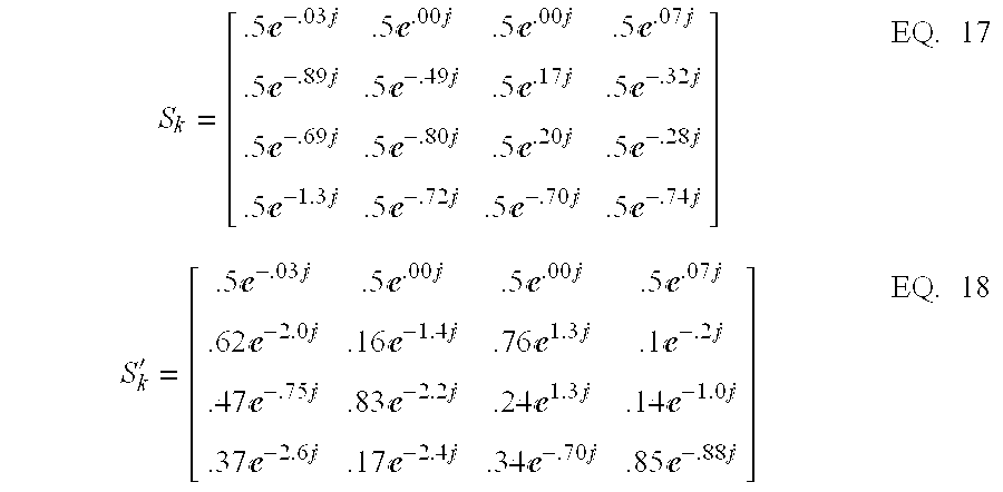
- It is noted that embodiments of the present invention, such as those described above, may be implemented in hardware, software, firmware, or a combination thereof. For example, in some embodiments, the present invention may be implemented as a computer program or application in software or firmware that is stored in a memory and that is executed by a suitable instruction execution system. In other embodiments the present invention may be implemented, for example, with one or a combination of the following technologies, which may be known in the art: one or more discrete logic circuit(s) having logic gates for implementing logic functions upon data signals, an application specific integrated circuit (ASIC) having appropriate combinational logic gates, a programmable gate array(s) (PGA), a field programmable gate array (FPGA), etc.
- It is further noted that any process descriptions or blocks in flow charts described above may represent modules, segments, and/or portions of a computer program or application code that includes one or more executable instructions for implementing specific logical functions or steps in the process. Alternate implementations are included within the scope of the present invention in which functions may be executed out of order from that shown in the figures and/or discussed above, including substantially concurrently or in reverse order, depending at least in part on the functionality involved, as will be understood by those skilled in the art.
- With regard to any block diagrams described above, although the flow of data or other elements may be depicted as unidirectional or bi-directional, such depictions are merely exemplary and not limiting. Variations of the flows depicted in the block diagrams are included within the scope of the present invention. Furthermore, the functionality of some of the blocks may be implemented by a single combined block within the scope of the present invention.
- Moreover, embodiments of the present invention, such as those described above, may comprise an ordered listing of executable instructions for implementing logical functions which can be embodied in any computer-readable medium for use by or in connection with an instruction execution system, apparatus, or device, such as a computer-based system, processor-containing system, or other system that can fetch the instructions from the instruction execution system, apparatus, or device and execute the instructions. In the context of this disclosure, a “computer-readable medium” may be any means that can contain, store, communicate, propagate, or transport the program for use by or in connection with the instruction execution system, apparatus, or device. The computer readable medium may be, for example but not limited to, an electronic, magnetic, optical, electromagnetic, infrared, or semiconductor system, apparatus, device, or propagation medium. More specific examples (i.e., a non-exhaustive list) of the computer-readable medium include the following: an electrical connection (electronic) having one or more wires, a portable computer diskette (magnetic), a random access memory (RAM) (electronic), a read-only memory (ROM) (electronic), an erasable programmable read-only memory (EPROM or Flash memory) (electronic), an optical fiber (optical), and a portable compact disc read-only memory (CDROM) (optical). It is noted that the computer-readable medium may even be paper or another suitable medium upon which the program is printed, as the program can be electronically captured, via for instance optical scanning of the paper or other medium, then compiled, interpreted or otherwise processed in a suitable manner if necessary, and then stored in a computer memory.
- Finally, it should be emphasized that the above-described embodiments of the present invention are merely possible examples of implementations set forth for a clear understanding of the principles of the invention. Many variations and modifications may be made to the above-described embodiment(s) of the invention without departing substantially from the spirit and principles of the invention. All such modifications and variations are intended to be included herein within the scope of this disclosure and the invention, and protected by the following claims.
Claims (21)


Priority Applications (3)
| Application Number | Priority Date | Filing Date | Title |
|---|---|---|---|
| US10/245,090 US7269224B2 (en) | 2001-09-17 | 2002-09-17 | Apparatus and methods for providing efficient space-time structures for preambles, pilots and data for multi-input, multi-output communications systems |
| US12/555,332 USRE43294E1 (en) | 2001-09-17 | 2009-09-08 | Apparatus and methods for providing efficient space-time structures for preambles, pilots and data for multi-input, multi-output communications systems |
| US13/418,626 USRE44867E1 (en) | 2001-09-17 | 2012-03-13 | Apparatus and methods for providing efficient space-time structures for preambles, pilots and data for multi-input, multi-output communications systems |
Applications Claiming Priority (3)
| Application Number | Priority Date | Filing Date | Title |
|---|---|---|---|
| US32278601P | 2001-09-17 | 2001-09-17 | |
| US32714501P | 2001-10-04 | 2001-10-04 | |
| US10/245,090 US7269224B2 (en) | 2001-09-17 | 2002-09-17 | Apparatus and methods for providing efficient space-time structures for preambles, pilots and data for multi-input, multi-output communications systems |
Related Parent Applications (1)
| Application Number | Title | Priority Date | Filing Date |
|---|---|---|---|
| US12/555,332 Continuation USRE43294E1 (en) | 2001-09-17 | 2009-09-08 | Apparatus and methods for providing efficient space-time structures for preambles, pilots and data for multi-input, multi-output communications systems |
Related Child Applications (2)
| Application Number | Title | Priority Date | Filing Date |
|---|---|---|---|
| US12/555,332 Reissue USRE43294E1 (en) | 2001-09-17 | 2009-09-08 | Apparatus and methods for providing efficient space-time structures for preambles, pilots and data for multi-input, multi-output communications systems |
| US13/418,626 Reissue USRE44867E1 (en) | 2001-09-17 | 2012-03-13 | Apparatus and methods for providing efficient space-time structures for preambles, pilots and data for multi-input, multi-output communications systems |
Publications (2)
| Publication Number | Publication Date |
|---|---|
| US20030076777A1 true US20030076777A1 (en) | 2003-04-24 |
| US7269224B2 US7269224B2 (en) | 2007-09-11 |
Family
ID=27399827
Family Applications (3)
| Application Number | Title | Priority Date | Filing Date |
|---|---|---|---|
| US10/245,090 Ceased US7269224B2 (en) | 2001-09-17 | 2002-09-17 | Apparatus and methods for providing efficient space-time structures for preambles, pilots and data for multi-input, multi-output communications systems |
| US12/555,332 Active 2024-07-21 USRE43294E1 (en) | 2001-09-17 | 2009-09-08 | Apparatus and methods for providing efficient space-time structures for preambles, pilots and data for multi-input, multi-output communications systems |
| US13/418,626 Active 2024-07-21 USRE44867E1 (en) | 2001-09-17 | 2012-03-13 | Apparatus and methods for providing efficient space-time structures for preambles, pilots and data for multi-input, multi-output communications systems |
Family Applications After (2)
| Application Number | Title | Priority Date | Filing Date |
|---|---|---|---|
| US12/555,332 Active 2024-07-21 USRE43294E1 (en) | 2001-09-17 | 2009-09-08 | Apparatus and methods for providing efficient space-time structures for preambles, pilots and data for multi-input, multi-output communications systems |
| US13/418,626 Active 2024-07-21 USRE44867E1 (en) | 2001-09-17 | 2012-03-13 | Apparatus and methods for providing efficient space-time structures for preambles, pilots and data for multi-input, multi-output communications systems |
Country Status (1)
| Country | Link |
|---|---|
| US (3) | US7269224B2 (en) |
Cited By (37)
| Publication number | Priority date | Publication date | Assignee | Title |
|---|---|---|---|---|
| US20050036481A1 (en) * | 2002-03-07 | 2005-02-17 | Naftali Chayat | Hierarchical preamble constructions for OFDMA based on complementary sequences |
| WO2005022776A2 (en) * | 2003-08-27 | 2005-03-10 | Kitakyushu Foundation For The Advancement Of Industry, Science And Technology | Communication method, communication system, and receiver |
| US20050078707A1 (en) * | 2003-09-30 | 2005-04-14 | Maltsev Alexander A. | Systems and methods for high-throughput wideband wireless local area network communications |
| US20050123060A1 (en) * | 2003-12-04 | 2005-06-09 | Intel Corporation | System and method for channelization recognition in a wideband communication system |
| US20050130684A1 (en) * | 2003-11-13 | 2005-06-16 | Samsung Electronics Co., Ltd. | Method for assigning channels based on spatial division multiplexing in an orthogonal frequency division multiplexing system with multiple antennas |
| WO2005057870A1 (en) * | 2003-12-05 | 2005-06-23 | Qualcomm Incorporated | Multi-antenna system to simultaneous support of miso and mimo receivers |
| US20050147022A1 (en) * | 2003-12-22 | 2005-07-07 | Texas Instruments Incorporated | Preamble transmit power tailoring system, a method of tailoring preamble transmit power and an OFDM transmitter employing the same |
| US20050233709A1 (en) * | 2003-04-10 | 2005-10-20 | Airgo Networks, Inc. | Modified preamble structure for IEEE 802.11a extensions to allow for coexistence and interoperability between 802.11a devices and higher data rate, MIMO or otherwise extended devices |
| US20050286474A1 (en) * | 2004-04-05 | 2005-12-29 | Airgo Networks, Inc. | Modified preamble structure for IEEE 802.11a extensions to allow for coexistence and interoperability between 802.11a devices and higher data rate, MIMO or otherwise extended devices |
| US20060104380A1 (en) * | 2004-11-17 | 2006-05-18 | Texas Instruments Incorporated | Time-switched preamble generation to enhance channel estimation signal-to-noise ratio in MIMO communication systems |
| US20060120268A1 (en) * | 2004-12-08 | 2006-06-08 | Yeheskel Bar-Ness | STBC MIMO-OFDM peak-to-average power ratio reduction by cross-antenna rotation and inversion |
| US20060245346A1 (en) * | 2004-12-02 | 2006-11-02 | Yeheskel Bar-Ness | Method and/or system for reduction of PAPR |
| US20060251193A1 (en) * | 2003-06-30 | 2006-11-09 | Kopmeiners Robert J | Methods and apparatus for backwards compatible communication in a multiple antenna communication system using time orthogonal symbols |
| US20060251183A1 (en) * | 2005-05-04 | 2006-11-09 | Menashe Soffer | Method for determining multiple-input multiple-output (MIMO) channel coefficient using polarity-inverted training signals in an orthogonal frequency division multiplexed (OFDM) multicarrier system |
| US20060252386A1 (en) * | 2003-06-30 | 2006-11-09 | Jan Boer | Methods and apparatus for backwards compatible communication in a multiple input multiple output communication system with lower order receivers |
| US20070064591A1 (en) * | 2005-09-21 | 2007-03-22 | Sanyo Electric Co., Ltd. | Radio apparatus |
| EP1768295A2 (en) * | 2005-09-27 | 2007-03-28 | Samsung Electronics Co., Ltd. | System and method for transmitting/receiving signal in a mobile communication system using a multiple input multiple output (MIMO) scheme |
| US20070217530A1 (en) * | 2006-03-17 | 2007-09-20 | Interdigital Technology Corporation | Method and apparatus for channel estimation using time-frequency localized pilots and de-noising techniques |
| US7301924B1 (en) | 2002-07-15 | 2007-11-27 | Cisco Technology, Inc. | Media access control for MIMO wireless network |
| CN100353698C (en) * | 2004-04-14 | 2007-12-05 | 美国博通公司 | Configuring a mimo communication |
| US20080005219A1 (en) * | 2006-01-10 | 2008-01-03 | Marvell International Ltd. | Transmission scheduling for receiver feedback |
| CN100362772C (en) * | 2004-06-29 | 2008-01-16 | 华为技术有限公司 | Receiver of multiple input and multiple output system |
| US7352718B1 (en) | 2003-07-22 | 2008-04-01 | Cisco Technology, Inc. | Spatial division multiple access for wireless networks |
| US7352688B1 (en) | 2002-12-31 | 2008-04-01 | Cisco Technology, Inc. | High data rate wireless bridging |
| US7453793B1 (en) * | 2003-04-10 | 2008-11-18 | Qualcomm Incorporated | Channel estimation for OFDM communication systems including IEEE 802.11A and extended rate systems |
| US20090028100A1 (en) * | 2007-07-25 | 2009-01-29 | Qualcomm Incorporated | Methods and apparatus for transmitter identification in a wireless network |
| US20090117917A1 (en) * | 2006-01-04 | 2009-05-07 | Qualcomm Incorporated | Methods and apparatus for position location in a wireless network |
| US20090190525A1 (en) * | 2008-01-28 | 2009-07-30 | Qualcomm Incorporated | Enhancements to the positioning pilot channel |
| US20090274099A1 (en) * | 2008-05-02 | 2009-11-05 | Qualcomm Incorporated | Methods and apparatus for communicating transmitter information in a communication network |
| US20100061402A1 (en) * | 2003-04-10 | 2010-03-11 | Qualcomm Incorporated | Modified preamble structure for ieee 802.11a extensions to allow for coexistence and interoperability between 802.11a devices and higher data rate, mimo or otherwise extended devices |
| US20100118993A1 (en) * | 2007-03-26 | 2010-05-13 | Rohde & Schwarz Gmbh & Co. Kg | Method and device for determining an unabbreviated channel-impulse response in an ofdm transmission system |
| US7813423B2 (en) | 2006-09-28 | 2010-10-12 | Samsung Electronics Co., Ltd. | Fast adaptive time domain hybrid equalizer for time reversal-space time block code system |
| US20110276592A1 (en) * | 2009-01-21 | 2011-11-10 | Sidharta Gautama | Geodatabase information processing |
| US8073072B2 (en) | 2003-11-04 | 2011-12-06 | Qualcomm Atheros, Inc. | Multiple-input multiple-output system and method |
| US20130208820A1 (en) * | 2003-12-30 | 2013-08-15 | Qinghua Li | Communication overhead reduction apparatus, systems, and methods |
| TWI499233B (en) * | 2005-09-15 | 2015-09-01 | Hera Wireless S A | Radio apparatus |
| US10700800B2 (en) | 2003-05-21 | 2020-06-30 | Regents Of The University Of Minnesota | Estimating frequency-offsets and multi-antenna channels in MIMO OFDM systems |
Families Citing this family (8)
| Publication number | Priority date | Publication date | Assignee | Title |
|---|---|---|---|---|
| US7952511B1 (en) | 1999-04-07 | 2011-05-31 | Geer James L | Method and apparatus for the detection of objects using electromagnetic wave attenuation patterns |
| US8363744B2 (en) | 2001-06-10 | 2013-01-29 | Aloft Media, Llc | Method and system for robust, secure, and high-efficiency voice and packet transmission over ad-hoc, mesh, and MIMO communication networks |
| US7394754B2 (en) * | 2002-08-01 | 2008-07-01 | Mediatek Inc. | System and method for transmitting data in a multiple-branch transmitter-diversity orthogonal frequency-division multiplexing (OFDM) system |
| JP2005110228A (en) * | 2003-09-10 | 2005-04-21 | Matsushita Electric Ind Co Ltd | Secure communication method, transmitting device, and receiving device |
| FR2860666A1 (en) * | 2003-10-03 | 2005-04-08 | France Telecom | METHOD FOR MULTI-ANTENNA TRANSMISSION OF BLOCK-SPACE-TIME CODED SIGNAL, RECOVERY METHOD AND CORRESPONDING SIGNAL |
| US20060023801A1 (en) * | 2004-07-28 | 2006-02-02 | Taarud Jeffrey E | Versatile system for optimizing transmit diversity in wireless communications |
| US20060140294A1 (en) * | 2004-11-05 | 2006-06-29 | Nokia Corporation | Block modulation |
| US11502414B2 (en) | 2021-01-29 | 2022-11-15 | Eagle Technology, Llc | Microstrip patch antenna system having adjustable radiation pattern shapes and related method |
Citations (18)
| Publication number | Priority date | Publication date | Assignee | Title |
|---|---|---|---|---|
| US31019A (en) * | 1861-01-01 | Hand-loom | ||
| US50964A (en) * | 1865-11-14 | Improved family-laundry | ||
| US53143A (en) * | 1866-03-13 | Improvement in shaft-couplings | ||
| US181390A (en) * | 1876-08-22 | Improvement in elastic link-bars for railroad-switches | ||
| US5732113A (en) * | 1996-06-20 | 1998-03-24 | Stanford University | Timing and frequency synchronization of OFDM signals |
| US6088408A (en) * | 1998-11-06 | 2000-07-11 | At & T Corp. | Decoding for generalized orthogonal designs for space-time codes for wireless communication |
| US6115427A (en) * | 1996-04-26 | 2000-09-05 | At&T Corp. | Method and apparatus for data transmission using multiple transmit antennas |
| US6125149A (en) * | 1997-11-05 | 2000-09-26 | At&T Corp. | Successively refinable trellis coded quantization |
| US6185258B1 (en) * | 1997-09-16 | 2001-02-06 | At&T Wireless Services Inc. | Transmitter diversity technique for wireless communications |
| US6188736B1 (en) * | 1997-12-23 | 2001-02-13 | At&T Wireless Svcs. Inc. | Near-optimal low-complexity decoding of space-time codes for fixed wireless applications |
| US6317411B1 (en) * | 1999-02-22 | 2001-11-13 | Motorola, Inc. | Method and system for transmitting and receiving signals transmitted from an antenna array with transmit diversity techniques |
| US20020003774A1 (en) * | 2000-07-05 | 2002-01-10 | Zhaocheng Wang | Pilot pattern design for a STTD scheme in an OFDM system |
| US20020044524A1 (en) * | 2000-09-13 | 2002-04-18 | Flarion Technologies, Inc. | OFDM communications methods and apparatus |
| US6542556B1 (en) * | 2000-03-31 | 2003-04-01 | Nokia Mobile Phones Ltd. | Space-time code for multiple antenna transmission |
| US6546055B1 (en) * | 1998-01-12 | 2003-04-08 | The Board Of Trustees Of The Leland Stanford Junior University | Carrier offset determination for RF signals having a cyclic prefix |
| US6549581B1 (en) * | 1998-06-15 | 2003-04-15 | Sony International (Europe) Gmbh | Transmitter and method to cancel interference in OFDM communication |
| US6693982B1 (en) * | 1997-10-06 | 2004-02-17 | At&T Corp. | Minimum mean squared error approach to interference cancellation and maximum likelihood decoding of space-time block codes |
| US6865237B1 (en) * | 2000-02-22 | 2005-03-08 | Nokia Mobile Phones Limited | Method and system for digital signal transmission |
Family Cites Families (17)
| Publication number | Priority date | Publication date | Assignee | Title |
|---|---|---|---|---|
| JPH0775099A (en) * | 1993-05-07 | 1995-03-17 | Philips Electron Nv | Transmission method, transmitter and receiver for transmitting multiplex orthogonal-amplitude-modulation type television |
| US6317466B1 (en) | 1998-04-15 | 2001-11-13 | Lucent Technologies Inc. | Wireless communications system having a space-time architecture employing multi-element antennas at both the transmitter and receiver |
| US6654429B1 (en) * | 1998-12-31 | 2003-11-25 | At&T Corp. | Pilot-aided channel estimation for OFDM in wireless systems |
| US6891903B2 (en) | 1999-04-22 | 2005-05-10 | At&T Corp. | Multiple transmit antenna differential detection from generalized orthogonal designs |
| US6757265B1 (en) * | 1999-07-30 | 2004-06-29 | Iospan Wireless, Inc. | Subscriber unit in a hybrid link incorporating spatial multiplexing |
| US6351499B1 (en) * | 1999-12-15 | 2002-02-26 | Iospan Wireless, Inc. | Method and wireless systems using multiple antennas and adaptive control for maximizing a communication parameter |
| US6804307B1 (en) * | 2000-01-27 | 2004-10-12 | Telefonaktiebolaget Lm Ericsson (Publ) | Method and apparatus for efficient transmit diversity using complex space-time block codes |
| US7068628B2 (en) | 2000-05-22 | 2006-06-27 | At&T Corp. | MIMO OFDM system |
| US7009931B2 (en) * | 2000-09-01 | 2006-03-07 | Nortel Networks Limited | Synchronization in a multiple-input/multiple-output (MIMO) orthogonal frequency division multiplexing (OFDM) system for wireless applications |
| US6985434B2 (en) * | 2000-09-01 | 2006-01-10 | Nortel Networks Limited | Adaptive time diversity and spatial diversity for OFDM |
| US7233625B2 (en) | 2000-09-01 | 2007-06-19 | Nortel Networks Limited | Preamble design for multiple input—multiple output (MIMO), orthogonal frequency division multiplexing (OFDM) system |
| KR100358120B1 (en) * | 2000-10-20 | 2002-10-25 | 한국전자통신연구원 | In-Band Adjascent-Channel Type Digital Audio Broadcasting Transmission System |
| US7054375B2 (en) * | 2000-12-22 | 2006-05-30 | Nokia Corporation | Method and apparatus for error reduction in an orthogonal modulation system |
| US7310304B2 (en) | 2001-04-24 | 2007-12-18 | Bae Systems Information And Electronic Systems Integration Inc. | Estimating channel parameters in multi-input, multi-output (MIMO) systems |
| US7088782B2 (en) | 2001-04-24 | 2006-08-08 | Georgia Tech Research Corporation | Time and frequency synchronization in multi-input, multi-output (MIMO) systems |
| US7027523B2 (en) * | 2001-06-22 | 2006-04-11 | Qualcomm Incorporated | Method and apparatus for transmitting data in a time division duplexed (TDD) communication system |
| US8116260B1 (en) * | 2001-08-22 | 2012-02-14 | At&T Intellectual Property Ii, L.P. | Simulcasting MIMO communication system |
-
2002
- 2002-09-17 US US10/245,090 patent/US7269224B2/en not_active Ceased
-
2009
- 2009-09-08 US US12/555,332 patent/USRE43294E1/en active Active
-
2012
- 2012-03-13 US US13/418,626 patent/USRE44867E1/en active Active
Patent Citations (18)
| Publication number | Priority date | Publication date | Assignee | Title |
|---|---|---|---|---|
| US50964A (en) * | 1865-11-14 | Improved family-laundry | ||
| US53143A (en) * | 1866-03-13 | Improvement in shaft-couplings | ||
| US181390A (en) * | 1876-08-22 | Improvement in elastic link-bars for railroad-switches | ||
| US31019A (en) * | 1861-01-01 | Hand-loom | ||
| US6115427A (en) * | 1996-04-26 | 2000-09-05 | At&T Corp. | Method and apparatus for data transmission using multiple transmit antennas |
| US5732113A (en) * | 1996-06-20 | 1998-03-24 | Stanford University | Timing and frequency synchronization of OFDM signals |
| US6185258B1 (en) * | 1997-09-16 | 2001-02-06 | At&T Wireless Services Inc. | Transmitter diversity technique for wireless communications |
| US6693982B1 (en) * | 1997-10-06 | 2004-02-17 | At&T Corp. | Minimum mean squared error approach to interference cancellation and maximum likelihood decoding of space-time block codes |
| US6125149A (en) * | 1997-11-05 | 2000-09-26 | At&T Corp. | Successively refinable trellis coded quantization |
| US6188736B1 (en) * | 1997-12-23 | 2001-02-13 | At&T Wireless Svcs. Inc. | Near-optimal low-complexity decoding of space-time codes for fixed wireless applications |
| US6546055B1 (en) * | 1998-01-12 | 2003-04-08 | The Board Of Trustees Of The Leland Stanford Junior University | Carrier offset determination for RF signals having a cyclic prefix |
| US6549581B1 (en) * | 1998-06-15 | 2003-04-15 | Sony International (Europe) Gmbh | Transmitter and method to cancel interference in OFDM communication |
| US6088408A (en) * | 1998-11-06 | 2000-07-11 | At & T Corp. | Decoding for generalized orthogonal designs for space-time codes for wireless communication |
| US6317411B1 (en) * | 1999-02-22 | 2001-11-13 | Motorola, Inc. | Method and system for transmitting and receiving signals transmitted from an antenna array with transmit diversity techniques |
| US6865237B1 (en) * | 2000-02-22 | 2005-03-08 | Nokia Mobile Phones Limited | Method and system for digital signal transmission |
| US6542556B1 (en) * | 2000-03-31 | 2003-04-01 | Nokia Mobile Phones Ltd. | Space-time code for multiple antenna transmission |
| US20020003774A1 (en) * | 2000-07-05 | 2002-01-10 | Zhaocheng Wang | Pilot pattern design for a STTD scheme in an OFDM system |
| US20020044524A1 (en) * | 2000-09-13 | 2002-04-18 | Flarion Technologies, Inc. | OFDM communications methods and apparatus |
Cited By (94)
| Publication number | Priority date | Publication date | Assignee | Title |
|---|---|---|---|---|
| US20050036481A1 (en) * | 2002-03-07 | 2005-02-17 | Naftali Chayat | Hierarchical preamble constructions for OFDMA based on complementary sequences |
| US7483367B2 (en) * | 2002-03-07 | 2009-01-27 | Alvaron Ltd. | Hierarchical preamble constructions for OFDMA based on complementary sequences |
| US7929412B1 (en) | 2002-07-15 | 2011-04-19 | Cisco Technology, Inc. | Media access control for MIMO wireless network |
| US7301924B1 (en) | 2002-07-15 | 2007-11-27 | Cisco Technology, Inc. | Media access control for MIMO wireless network |
| US9236928B1 (en) | 2002-07-15 | 2016-01-12 | Cisco Technology, Inc. | Media access control for MIMO wireless network |
| US8625507B1 (en) | 2002-07-15 | 2014-01-07 | Cisco Technology, Inc. | Media access control for MIMO wireless network |
| US8374105B1 (en) | 2002-12-31 | 2013-02-12 | Cisco Technology, Inc. | High data rate wireless bridging |
| US7352688B1 (en) | 2002-12-31 | 2008-04-01 | Cisco Technology, Inc. | High data rate wireless bridging |
| US7453793B1 (en) * | 2003-04-10 | 2008-11-18 | Qualcomm Incorporated | Channel estimation for OFDM communication systems including IEEE 802.11A and extended rate systems |
| US20050233709A1 (en) * | 2003-04-10 | 2005-10-20 | Airgo Networks, Inc. | Modified preamble structure for IEEE 802.11a extensions to allow for coexistence and interoperability between 802.11a devices and higher data rate, MIMO or otherwise extended devices |
| US7916803B2 (en) * | 2003-04-10 | 2011-03-29 | Qualcomm Incorporated | Modified preamble structure for IEEE 802.11a extensions to allow for coexistence and interoperability between 802.11a devices and higher data rate, MIMO or otherwise extended devices |
| US8743837B2 (en) | 2003-04-10 | 2014-06-03 | Qualcomm Incorporated | Modified preamble structure for IEEE 802.11A extensions to allow for coexistence and interoperability between 802.11A devices and higher data rate, MIMO or otherwise extended devices |
| US20100061402A1 (en) * | 2003-04-10 | 2010-03-11 | Qualcomm Incorporated | Modified preamble structure for ieee 802.11a extensions to allow for coexistence and interoperability between 802.11a devices and higher data rate, mimo or otherwise extended devices |
| US11303377B2 (en) | 2003-05-21 | 2022-04-12 | Regents Of The University Of Minnesota | Estimating frequency-offsets and multi-antenna channels in MIMO OFDM systems |
| US10700800B2 (en) | 2003-05-21 | 2020-06-30 | Regents Of The University Of Minnesota | Estimating frequency-offsets and multi-antenna channels in MIMO OFDM systems |
| US20060252386A1 (en) * | 2003-06-30 | 2006-11-09 | Jan Boer | Methods and apparatus for backwards compatible communication in a multiple input multiple output communication system with lower order receivers |
| US20060251193A1 (en) * | 2003-06-30 | 2006-11-09 | Kopmeiners Robert J | Methods and apparatus for backwards compatible communication in a multiple antenna communication system using time orthogonal symbols |
| US8014267B2 (en) * | 2003-06-30 | 2011-09-06 | Agere Systems Inc. | Methods and apparatus for backwards compatible communication in a multiple input multiple output communication system with lower order receivers |
| US7885177B2 (en) * | 2003-06-30 | 2011-02-08 | Agere Systems Inc. | Methods and apparatus for backwards compatible communication in a multiple antenna communication system using time orthogonal symbols |
| US7352718B1 (en) | 2003-07-22 | 2008-04-01 | Cisco Technology, Inc. | Spatial division multiple access for wireless networks |
| US9131029B1 (en) | 2003-07-22 | 2015-09-08 | Cisco Technology, Inc. | Spatial division multiple access for wireless networks |
| US8737328B1 (en) | 2003-07-22 | 2014-05-27 | Cisco Technology, Inc. | Spatial division multiple access for wireless networks |
| US7995525B1 (en) | 2003-07-22 | 2011-08-09 | Cisco Technology, Inc. | Spatial division multiple access for wireless networks |
| WO2005022776A3 (en) * | 2003-08-27 | 2005-04-21 | Kitakyushu Foundation | Communication method, communication system, and receiver |
| WO2005022776A2 (en) * | 2003-08-27 | 2005-03-10 | Kitakyushu Foundation For The Advancement Of Industry, Science And Technology | Communication method, communication system, and receiver |
| US7349436B2 (en) | 2003-09-30 | 2008-03-25 | Intel Corporation | Systems and methods for high-throughput wideband wireless local area network communications |
| US8780824B2 (en) | 2003-09-30 | 2014-07-15 | Intel Corporation | High throughput communication station and method for communicating over a primary channel and a secondary channel |
| US7826484B2 (en) | 2003-09-30 | 2010-11-02 | Intel Corporation | Systems and methods for high-throughput wideband wireless local area network communications |
| US20050078707A1 (en) * | 2003-09-30 | 2005-04-14 | Maltsev Alexander A. | Systems and methods for high-throughput wideband wireless local area network communications |
| US20110044392A1 (en) * | 2003-09-30 | 2011-02-24 | Maltsev Alexander A | Systems And Methods For High-Throughput Wideband Wireless Local Area Network Communications |
| US20080144732A1 (en) * | 2003-09-30 | 2008-06-19 | Intel Corporation | Systems and methods for high-throughput wideband wireless local area network communications |
| US8599953B2 (en) | 2003-11-04 | 2013-12-03 | Qualcomm Incorporated | Multiple-input multiple-output system and method |
| US8989294B2 (en) | 2003-11-04 | 2015-03-24 | Qualcomm Incorporated | Multiple-input multiple-output system and method |
| US8073072B2 (en) | 2003-11-04 | 2011-12-06 | Qualcomm Atheros, Inc. | Multiple-input multiple-output system and method |
| US10447437B2 (en) | 2003-11-13 | 2019-10-15 | Samsung Electronics Co., Ltd | Method for assigning channels based on spatial division multiplexing in an orthogonal frequency division multiplexing system with multiple antennas |
| US20080137764A1 (en) * | 2003-11-13 | 2008-06-12 | Samsung Electronics Co., Ltd. | Method for assigning channels based on spatial division multiplexing in an orthogonal frequency division multiplexing system with multiple antennas |
| EP1742405A1 (en) * | 2003-11-13 | 2007-01-10 | Samsung Electronics Co., Ltd. | Method for channel estimation with spatial division multiplexing in an orthogonal frequency division multiplexing system with multiple antennas |
| US20050130684A1 (en) * | 2003-11-13 | 2005-06-16 | Samsung Electronics Co., Ltd. | Method for assigning channels based on spatial division multiplexing in an orthogonal frequency division multiplexing system with multiple antennas |
| US7319685B2 (en) | 2003-11-13 | 2008-01-15 | Samsung Electronics Co., Ltd. | Method for assigning channels based on spatial division multiplexing in an orthogonal frequency division multiplexing system with multiple antennas |
| US20050123060A1 (en) * | 2003-12-04 | 2005-06-09 | Intel Corporation | System and method for channelization recognition in a wideband communication system |
| US7286606B2 (en) * | 2003-12-04 | 2007-10-23 | Intel Corporation | System and method for channelization recognition in a wideband communication system |
| TWI385948B (en) * | 2003-12-05 | 2013-02-11 | Qualcomm Inc | Pilot transmission schemes for a multi-antenna system |
| AU2004297958B2 (en) * | 2003-12-05 | 2008-09-04 | Qualcomm Incorporated | Multi-antenna system to simultaneous support of MISO and MIMO receivers |
| WO2005057870A1 (en) * | 2003-12-05 | 2005-06-23 | Qualcomm Incorporated | Multi-antenna system to simultaneous support of miso and mimo receivers |
| AU2004297958C1 (en) * | 2003-12-05 | 2009-06-25 | Qualcomm Incorporated | Multi-antenna system to simultaneous support of MISO and MIMO receivers |
| US7145940B2 (en) | 2003-12-05 | 2006-12-05 | Qualcomm Incorporated | Pilot transmission schemes for a multi-antenna system |
| JP2007513584A (en) * | 2003-12-05 | 2007-05-24 | クゥアルコム・インコーポレイテッド | Multi-antenna system supporting MISO and MIMO receivers simultaneously |
| EP2202928A1 (en) * | 2003-12-05 | 2010-06-30 | Qualcom Incorporated | Channel estimation for simultaneous support of MISO and MIMO receivers |
| EP2202929A1 (en) * | 2003-12-05 | 2010-06-30 | Qualcom Incorporated | Channel estimation in a MISO receiver |
| EP2202927A1 (en) * | 2003-12-05 | 2010-06-30 | Qualcom Incorporated | Channel estimation in a MIMO-OFDM receiver |
| EP2202926A1 (en) * | 2003-12-05 | 2010-06-30 | Qualcom Incorporated | Method of transmitting a pilot to simultaneous support of MISO and MIMO receivers |
| KR100820998B1 (en) * | 2003-12-05 | 2008-04-08 | 콸콤 인코포레이티드 | Multi-antenna system to simultaneous support of miso and mimo receivers |
| US20050147022A1 (en) * | 2003-12-22 | 2005-07-07 | Texas Instruments Incorporated | Preamble transmit power tailoring system, a method of tailoring preamble transmit power and an OFDM transmitter employing the same |
| US8948195B2 (en) * | 2003-12-30 | 2015-02-03 | Intel Corporation | Communication overhead reduction apparatus, systems, and methods |
| US20130208820A1 (en) * | 2003-12-30 | 2013-08-15 | Qinghua Li | Communication overhead reduction apparatus, systems, and methods |
| US9407348B2 (en) | 2003-12-30 | 2016-08-02 | Intel Corporation | Communication overhead reduction apparatus, systems, and methods |
| US20050286474A1 (en) * | 2004-04-05 | 2005-12-29 | Airgo Networks, Inc. | Modified preamble structure for IEEE 802.11a extensions to allow for coexistence and interoperability between 802.11a devices and higher data rate, MIMO or otherwise extended devices |
| US7599332B2 (en) * | 2004-04-05 | 2009-10-06 | Qualcomm Incorporated | Modified preamble structure for IEEE 802.11a extensions to allow for coexistence and interoperability between 802.11a devices and higher data rate, MIMO or otherwise extended devices |
| CN100353698C (en) * | 2004-04-14 | 2007-12-05 | 美国博通公司 | Configuring a mimo communication |
| CN100362772C (en) * | 2004-06-29 | 2008-01-16 | 华为技术有限公司 | Receiver of multiple input and multiple output system |
| US20060104380A1 (en) * | 2004-11-17 | 2006-05-18 | Texas Instruments Incorporated | Time-switched preamble generation to enhance channel estimation signal-to-noise ratio in MIMO communication systems |
| US20060245346A1 (en) * | 2004-12-02 | 2006-11-02 | Yeheskel Bar-Ness | Method and/or system for reduction of PAPR |
| US8040787B2 (en) * | 2004-12-02 | 2011-10-18 | New Jersey Institute Of Technology | Method and/or system for reduction of PAPR |
| USRE41433E1 (en) | 2004-12-08 | 2010-07-13 | New Jersey Institute Of Technology | STBC MIMO-OFDM peak-to-average power ratio reduction by cross-antenna rotation and inversion |
| US7339884B2 (en) * | 2004-12-08 | 2008-03-04 | New Jersey Institute Of Technology | STBC MIMO-OFDM peak-to-average power ratio reduction by cross-antenna rotation and inversion |
| US20060120268A1 (en) * | 2004-12-08 | 2006-06-08 | Yeheskel Bar-Ness | STBC MIMO-OFDM peak-to-average power ratio reduction by cross-antenna rotation and inversion |
| US20060251183A1 (en) * | 2005-05-04 | 2006-11-09 | Menashe Soffer | Method for determining multiple-input multiple-output (MIMO) channel coefficient using polarity-inverted training signals in an orthogonal frequency division multiplexed (OFDM) multicarrier system |
| US7499504B2 (en) * | 2005-05-04 | 2009-03-03 | Intel Corporation | Method for determining multiple-input multiple-output (MIMO) channel coefficient using polarity-inverted training signals in an orthogonal frequency division multiplexed (OFDM) multicarrier system |
| TWI499233B (en) * | 2005-09-15 | 2015-09-01 | Hera Wireless S A | Radio apparatus |
| TWI411253B (en) * | 2005-09-21 | 2013-10-01 | Sanyo Electric Co | Radio apparatus |
| WO2007034724A1 (en) * | 2005-09-21 | 2007-03-29 | Sanyo Electric Co., Ltd. | Apparatus with training signals in an ofdm mimo system |
| US8228921B2 (en) | 2005-09-21 | 2012-07-24 | Hera Wireless S.A. | Radio apparatus |
| US20070064591A1 (en) * | 2005-09-21 | 2007-03-22 | Sanyo Electric Co., Ltd. | Radio apparatus |
| EP1768295A3 (en) * | 2005-09-27 | 2011-12-28 | Samsung Electronics Co., Ltd. | System and method for transmitting/receiving signal in a mobile communication system using a multiple input multiple output (MIMO) scheme |
| EP1768295A2 (en) * | 2005-09-27 | 2007-03-28 | Samsung Electronics Co., Ltd. | System and method for transmitting/receiving signal in a mobile communication system using a multiple input multiple output (MIMO) scheme |
| US8489124B2 (en) | 2006-01-04 | 2013-07-16 | Qualcomm Incorporated | Methods and apparatus for position location in a wireless network |
| US9008700B2 (en) | 2006-01-04 | 2015-04-14 | Qualcomm Incorporated | Methods and apparatus for position location in a wireless network |
| US20090117917A1 (en) * | 2006-01-04 | 2009-05-07 | Qualcomm Incorporated | Methods and apparatus for position location in a wireless network |
| US8155597B2 (en) * | 2006-01-10 | 2012-04-10 | Marvell World Trade Ltd. | Transmission scheduling for receiver feedback |
| US20130244586A1 (en) * | 2006-01-10 | 2013-09-19 | Marvell World Trade Ltd. | Sub-carrier and channel matrix element order for receiver feedback |
| US20080005219A1 (en) * | 2006-01-10 | 2008-01-03 | Marvell International Ltd. | Transmission scheduling for receiver feedback |
| US8442450B1 (en) | 2006-01-10 | 2013-05-14 | Marvell World Trade Ltd. | Sub-carrier and channel matrix element ordering for receiver feedback |
| US8838041B2 (en) * | 2006-01-10 | 2014-09-16 | Marvell World Trade Ltd. | Sub-carrier and channel matrix element order for receiver feedback |
| US20070217530A1 (en) * | 2006-03-17 | 2007-09-20 | Interdigital Technology Corporation | Method and apparatus for channel estimation using time-frequency localized pilots and de-noising techniques |
| US7769075B2 (en) * | 2006-03-17 | 2010-08-03 | Interdigital Technology Corporation | Method and apparatus for channel estimation using time-frequency localized pilots and de-noising techniques |
| US7813423B2 (en) | 2006-09-28 | 2010-10-12 | Samsung Electronics Co., Ltd. | Fast adaptive time domain hybrid equalizer for time reversal-space time block code system |
| US8374262B2 (en) * | 2007-03-26 | 2013-02-12 | Rohde & Schwarz Gmbh & Co. Kg | Method and device for determining an unabbreviated channel-impulse response in an OFDM transmission system |
| US20100118993A1 (en) * | 2007-03-26 | 2010-05-13 | Rohde & Schwarz Gmbh & Co. Kg | Method and device for determining an unabbreviated channel-impulse response in an ofdm transmission system |
| US20090028100A1 (en) * | 2007-07-25 | 2009-01-29 | Qualcomm Incorporated | Methods and apparatus for transmitter identification in a wireless network |
| US8165064B2 (en) | 2008-01-28 | 2012-04-24 | Qualcomm Incorporated | Enhancements to the positioning pilot channel |
| US20090190525A1 (en) * | 2008-01-28 | 2009-07-30 | Qualcomm Incorporated | Enhancements to the positioning pilot channel |
| US20090274099A1 (en) * | 2008-05-02 | 2009-11-05 | Qualcomm Incorporated | Methods and apparatus for communicating transmitter information in a communication network |
| US20110276592A1 (en) * | 2009-01-21 | 2011-11-10 | Sidharta Gautama | Geodatabase information processing |
| US9171485B2 (en) * | 2009-01-21 | 2015-10-27 | Universiteit Gent | Geodatabase information processing |
Also Published As
| Publication number | Publication date |
|---|---|
| US7269224B2 (en) | 2007-09-11 |
| USRE43294E1 (en) | 2012-04-03 |
| USRE44867E1 (en) | 2014-04-29 |
Similar Documents
| Publication | Publication Date | Title |
|---|---|---|
| US7269224B2 (en) | Apparatus and methods for providing efficient space-time structures for preambles, pilots and data for multi-input, multi-output communications systems | |
| US7269127B2 (en) | Preamble structures for single-input, single-output (SISO) and multi-input, multi-output (MIMO) communication systems | |
| US7782573B2 (en) | Trellis-based feedback reduction for multiple input multiple output orthogonal frequency division multiplexing (MIMO-OFDM) with rate-limited feedback | |
| US8111772B2 (en) | Method and apparatus for multi-antenna transmitting based on spatial-frequency encoding | |
| CN1838581B (en) | Transreceiving apparatus and method using space-frequency block-coded single-carrier frequency domain equalization | |
| KR100708188B1 (en) | Method of channel estimation for MIMO-OFDM using phase rotated low overhead preamble | |
| KR101434704B1 (en) | Method of radio data emission, emitter and receiver using the method | |
| US20040082303A1 (en) | Space-time doppler coding schemes for time-selective wireless communication channels | |
| KR100817497B1 (en) | Apparatus and method for generating simbol for multiple antennas | |
| WO2005050885A1 (en) | Multi-antenna receiving apparatus, multi-antenna receiving method, multi-antenna transmitting apparatus, and multi-antenna communication system | |
| JP5102305B2 (en) | System and method for block-coded transmission of single carrier spatial frequency over fast fading channel with frequency selectivity | |
| CN105306118A (en) | Broadband asynchronous adjustable multi-carrier wireless transmission method and system supporting multi-antenna transmission | |
| CN101296012B (en) | Method for pilot frequency insertion and diversity emission of space-frequency encoding cascade cycle detention diversity | |
| US8014463B2 (en) | Delay diversity and spatial rotation systems and methods | |
| CN101083515A (en) | Channel estimation method and apparatus for OFDM of transmission diversity | |
| US8111660B2 (en) | Method and transmitter for transmitting data in a multi-carrier system via a number of transmitting antennas | |
| KR101159262B1 (en) | Method for the multi-antennae emission of a signal by unitary space-time codes, receiving method, and corresponding signal | |
| US20080165882A1 (en) | Method and System for Resizing a MIMO Channel | |
| CN106341362A (en) | Pilot frequency transmission method, pilot frequency receiving method and devices thereof | |
| CN1816027B (en) | Iterative channel estimation method in multi-antenna multi-carrier-wave wireless telecommunication system | |
| CN101296010B (en) | Channel estimation method suitable for space-frequency encoding cascade cycle detention diversity mode | |
| CN101102295A (en) | Method for space collection multiplexing and multi-input and output communication system | |
| KR100843251B1 (en) | Apparatus and method for transmitting signal with multiple antennas | |
| CN102447658B (en) | Method and device for suppressing and merging interference | |
| CN106101033A (en) | A kind of IAM channel estimation methods being applicable to MIMO FBMC system |
Legal Events
| Date | Code | Title | Description |
|---|---|---|---|
| AS | Assignment |
Owner name: GEORGIA TECH RESEARCH CORPORATION, GEORGIA Free format text: ASSIGNMENT OF ASSIGNORS INTEREST;ASSIGNORS:STUBER, GORDON L.;MODY, APURVA N.;REEL/FRAME:013568/0493;SIGNING DATES FROM 20021126 TO 20021127 |
|
| AS | Assignment |
Owner name: BAE SYSTEMS INFORMATION AND ELECTRONIC SYSTEMS INT Free format text: ASSIGNMENT OF ASSIGNORS INTEREST;ASSIGNOR:GEORGIA TECH RESEARCH CORP.;REEL/FRAME:019183/0600 Effective date: 20070411 |
|
| STCF | Information on status: patent grant |
Free format text: PATENTED CASE |
|
| FEPP | Fee payment procedure |
Free format text: PAYOR NUMBER ASSIGNED (ORIGINAL EVENT CODE: ASPN); ENTITY STATUS OF PATENT OWNER: LARGE ENTITY |
|
| FEPP | Fee payment procedure |
Free format text: PAYOR NUMBER ASSIGNED (ORIGINAL EVENT CODE: ASPN); ENTITY STATUS OF PATENT OWNER: LARGE ENTITY Free format text: PAYER NUMBER DE-ASSIGNED (ORIGINAL EVENT CODE: RMPN); ENTITY STATUS OF PATENT OWNER: LARGE ENTITY |
|
| FEPP | Fee payment procedure |
Free format text: PAT HOLDER NO LONGER CLAIMS SMALL ENTITY STATUS, ENTITY STATUS SET TO UNDISCOUNTED (ORIGINAL EVENT CODE: STOL); ENTITY STATUS OF PATENT OWNER: LARGE ENTITY |
|
| AS | Assignment |
Owner name: TAFFCO THREE FUND, L.L.C., DELAWARE Free format text: ASSIGNMENT OF ASSIGNORS INTEREST;ASSIGNOR:BAE SYSTEMS INFORMATION AND ELECTRONIC SYSTEMS INTEGRATION INC.;REEL/FRAME:022277/0505 Effective date: 20081219 |
|
| RF | Reissue application filed |
Effective date: 20090908 |
|
| FPAY | Fee payment |
Year of fee payment: 4 |
|
| RF | Reissue application filed |
Effective date: 20120313 |
|
| FEPP | Fee payment procedure |
Free format text: PAYER NUMBER DE-ASSIGNED (ORIGINAL EVENT CODE: RMPN); ENTITY STATUS OF PATENT OWNER: LARGE ENTITY Free format text: PAYOR NUMBER ASSIGNED (ORIGINAL EVENT CODE: ASPN); ENTITY STATUS OF PATENT OWNER: LARGE ENTITY |
|
| AS | Assignment |
Owner name: CALLAHAN CELLULAR L.L.C., DELAWARE Free format text: MERGER;ASSIGNOR:TAFFCO THREE FUND, L.L.C.;REEL/FRAME:037358/0869 Effective date: 20150827 |