US20030113014A1 - Color reproduction corrector for image input device and color reproduction correction method - Google Patents
Color reproduction corrector for image input device and color reproduction correction method Download PDFInfo
- Publication number
- US20030113014A1 US20030113014A1 US10/169,417 US16941702A US2003113014A1 US 20030113014 A1 US20030113014 A1 US 20030113014A1 US 16941702 A US16941702 A US 16941702A US 2003113014 A1 US2003113014 A1 US 2003113014A1
- Authority
- US
- United States
- Prior art keywords
- transformation matrix
- light source
- color reproduction
- color
- data
- Prior art date
- Legal status (The legal status is an assumption and is not a legal conclusion. Google has not performed a legal analysis and makes no representation as to the accuracy of the status listed.)
- Granted
Links
- 238000000034 method Methods 0.000 title claims description 50
- 239000011159 matrix material Substances 0.000 claims abstract description 268
- 230000009466 transformation Effects 0.000 claims abstract description 180
- 238000004519 manufacturing process Methods 0.000 claims abstract description 54
- 239000003086 colorant Substances 0.000 claims abstract description 31
- 230000003287 optical effect Effects 0.000 claims abstract description 20
- 230000003595 spectral effect Effects 0.000 claims abstract description 17
- 238000004737 colorimetric analysis Methods 0.000 claims description 45
- 238000000513 principal component analysis Methods 0.000 claims description 18
- 238000004458 analytical method Methods 0.000 claims description 17
- 238000009877 rendering Methods 0.000 abstract description 5
- 239000013598 vector Substances 0.000 description 13
- 230000006870 function Effects 0.000 description 10
- 238000004364 calculation method Methods 0.000 description 3
- 230000007423 decrease Effects 0.000 description 3
- 238000010586 diagram Methods 0.000 description 3
- 230000014759 maintenance of location Effects 0.000 description 3
- 230000004044 response Effects 0.000 description 3
- 230000000007 visual effect Effects 0.000 description 3
- 230000005457 Black-body radiation Effects 0.000 description 2
- 230000014509 gene expression Effects 0.000 description 2
- 230000017105 transposition Effects 0.000 description 2
- 239000000470 constituent Substances 0.000 description 1
- 230000003247 decreasing effect Effects 0.000 description 1
Images


Classifications
-
- H—ELECTRICITY
- H04—ELECTRIC COMMUNICATION TECHNIQUE
- H04N—PICTORIAL COMMUNICATION, e.g. TELEVISION
- H04N1/00—Scanning, transmission or reproduction of documents or the like, e.g. facsimile transmission; Details thereof
- H04N1/46—Colour picture communication systems
- H04N1/56—Processing of colour picture signals
- H04N1/60—Colour correction or control
- H04N1/6083—Colour correction or control controlled by factors external to the apparatus
-
- H—ELECTRICITY
- H04—ELECTRIC COMMUNICATION TECHNIQUE
- H04N—PICTORIAL COMMUNICATION, e.g. TELEVISION
- H04N23/00—Cameras or camera modules comprising electronic image sensors; Control thereof
- H04N23/80—Camera processing pipelines; Components thereof
- H04N23/84—Camera processing pipelines; Components thereof for processing colour signals
- H04N23/88—Camera processing pipelines; Components thereof for processing colour signals for colour balance, e.g. white-balance circuits or colour temperature control
-
- H—ELECTRICITY
- H04—ELECTRIC COMMUNICATION TECHNIQUE
- H04N—PICTORIAL COMMUNICATION, e.g. TELEVISION
- H04N9/00—Details of colour television systems
- H04N9/64—Circuits for processing colour signals
- H04N9/73—Colour balance circuits, e.g. white balance circuits or colour temperature control
Definitions
- the present invention relates to a color reproduction correcting device and a color reproduction correcting method for an image input apparatus. Particularly, the invention relates to a color reproduction correcting device and method therefor to reproduce colors of the image at a desired level of color rendition under the same visual environment or under a different visual environment.
- an image picked up by an image input apparatus such as a camera is differently viewed depending on a visual environment at the time of observation, and there are cases where images are not reproduced with desired colors.
- the image picked up under a D65 light source of a sunlight type has been observed under an F5 light source of a high-efficiency fluorescent lamp type
- the reproduced colors greatly differ from each other.
- a light source of a sunlight type is known for having a high level color-rendering property and a light source of a fluorescent lamp type is known for having a low level color-rendering property.
- a light source of a fluorescent lamp type is known for having a low level color-rendering property.
- the white balance is a technique which performs correction to reproduce an achromatic color as it is. Therefore, in a case where the color rendition of the image pick-up light source and that of the observation light source greatly differ, there is a problem that the chromatic colors may not be excellently reproduced by the color reproduction correcting where only the white balance is used.
- the present invention has been made in view of the above-described problems and an object of the invention is to provide a color reproduction correcting device and a color reproduction correcting method for an image input apparatus, in which colors are excellently reproduced without difficulties even when the image has been reproduced under an observation light source whose color rendering property is different from that of the image pick-up light source.
- the color reproduction correcting device performs color reproduction correction with respect to image data of an image picked up by the image input apparatus which outputs information on the type of a image pick-up light source and information containing chromaticity point data of the image pick-up light source, that is information on the estimated result of the image pick-up light source.
- the color reproduction correcting device includes: white balance matrix production means for receiving the chromaticity point data from the image input apparatus to produce a correction matrix for white balance, light source type determination means for receiving information on the image pick-up light source from the image input apparatus to determine the types of the image pick-up light source and an image color reproduction light source, transformation matrix production means for producing a transformation matrix reflecting the optical characteristics of the picked-up object by using predetermined color matching function data, spectral characteristic data on the image pick-up light source and color reproduction light source determined by the light source type determination means, optical characteristic data on a predetermined picked-up object, and correction matrix data for white balance, and color correction processing means for performing color reproduction correction with respect to the image data by using the transformation matrix.
- the color reproduction correcting device in the first aspect of the invention further includes weighted transformation matrix production means for applying a predetermined constant as a weighting factor and calculating a sum of the product of the transformation matrix and the weighting factor and the product of the unit matrix in the same size as that of the transformation matrix and the weighting factor, to produce weighted transformation matrix, and then the color correction processing means uses the weighted transformation matrix as a transformation matrix for color reproduction correction.
- the transformation matrix produced in the transformation matrix production means is the matrix to which white balance is applied; and the color correction processing means uses the transformation matrix to which white balance is applied as a transformation matrix for color reproduction correction under the same type of light source.
- the optical characteristic data of the picked-up object includes principal component analysis data obtained by that analysis, or colorimetry data obtained by performing colorimetry with respect to a picked-up object whose colors are equally distributed in a color space, and then the color correction processing means uses the transformation matrix produced by the transformation matrix production means which uses the principal component analysis data or the colorimetry data, as the transformation matrix for performing color reproduction correction.
- the color reproduction correcting method comprises the steps of: receiving the chromaticity point data from the image input apparatus to produce a correction matrix for white balance, receiving information on the image pick-up light source from the image input apparatus to determine the types of the image pick-up light source and an image color reproduction light source, producing a transformation matrix which reflects the optical characteristics of the picked-up object by using predetermined color matching function data, spectral characteristic data on the image pick-up light source and color reproduction light source determined by the light source type determination means, optical characteristic data on a predetermined picked-up object, and correction matrix data for white balance, and performing a color correction processing with respect to the image data by using the transformation matrix.
- the color reproduction correcting method in the fifth aspect of the invention further comprises the step of applying a predetermined constant as a weighting factor and calculating a sum of the product of the transformation matrix and the weighting factor and the product of the unit matrix in the same size as that of the transformation matrix and the weighting factor, to produce weighted transformation matrix, and then the color correction processing step uses the weighted transformation matrix as a transformation matrix for color reproduction correction.
- the transformation matrix produced in the transformation matrix production step is the matrix to which white balance is applied; and the color correction processing step uses the transformation matrix to which white balance is applied, as a transformation matrix for color reproduction correction under the same type of light source.
- the optical characteristics data of the picked-up object includes principal component analysis data obtained by that analyses or colorimetry data obtained by performing colorimetry with respect to a picked-up object whose colors are equally distributed in a color space, and then the color correction processing step uses the transformation matrix produced by the transformation matrix production step which uses the principal component analysis data or the colorimetry data, as the transformation matrix for performing color reproduction correction.
- FIG. 1 is a block diagram illustrating the entire configuration of a color reproduction correcting device according to a first embodiment of the present invention
- FIG. 2 is a view illustrating an example of the most contributory three characteristic vectors that are obtained in the principal component analyses
- FIG. 3 is a flow chart illustrating the flow of the processing to produce a transformation matrix used in the color reproduction correction of the color reproduction correcting method according to the first embodiment
- FIG. 4 is a flow chart illustrating the flow of the color reproduction correction processing in the color reproduction correcting method according to the first embodiment
- FIG. 5 is a block diagram illustrating the entire configuration of the color reproduction correcting device according to a second embodiment of the present invention.
- FIG. 6 is a flow chart illustrating the flow of the processing to produce a weighted transformation matrix according to the second embodiment of the present invention
- FIG. 7 is a block diagram illustrating the entire configuration of the color reproduction correcting device according to a third embodiment of the present invention.
- FIG. 8 is a flow chart illustrating the flow of the processing to produce a transformation matrix using the colorimetry data according to the third embodiment of the present invention.
- FIG. 1 is a view illustrating the entire configuration of a color reproduction correcting device according to a first embodiment of the present invention.
- the color reproduction correcting device 100 comprises an operation unit 110 , a control unit 120 , a white balance matrix production unit 130 , a light source type determination unit 140 , a transformation matrix production unit 150 , storage unit 160 , and a color correction processing unit 170 .
- the control unit 120 is connected to each of the other constituent parts and thereby controls those respective parts.
- the operation unit 110 is equipped with an image monitor (not illustrated) on which a menu screen to perform setting etc. necessary for the color reproduction correction is displayed, and the setting is performed by using keys, or the like, of the operation unit 110 . Further, by the operation unit 110 , instructions on start, stop, etc. of processing, data input, and the other input are performed. Furthermore, the states of the processing at the respective units, the processed results of them, etc. are displayed on the image monitor. The output of the operation unit 110 is transmitted to the control unit 120 , or transmitted to the respective units through the control unit 120 .
- the control unit 120 performs processing such as outputting predetermined instructions, data, etc. to the respective processing units according to the setting, instructions, data, etc. output from the operation unit 110 and outputting instructions, data, etc. to the other units according to signals output from the respective units to the control unit 120 .
- the control unit 120 performs the following processing such as reading out data from the storage unit 160 as later described in response to a request from the transformation matrix production unit 150 as later described to output data to the transformation matrix production unit 150 and outputting the result being output from the transformation matrix production unit 150 to the color correction processing unit 170 , or the like.
- the control unit 120 controls the respective units to produce and update a transformation matrix for use in color reproduction correction and the control unit 120 controls color reproduction correction using the updated transformation matrix.
- the white balance matrix production unit 130 receives the chromaticity point data CD on the estimated light source, i.e. (RW, GW, BW), to produce a correction matrix M (WB) for use in white balance according to the following equation (1).
- M ⁇ ( WB ) [ 1 / RW 0 0 0 1 / GW 0 0 0 1 / BW ] ( 1 )
- the RW, GW, and BW respectively represent the R (red), G (green), and B (blue) components of the chromaticity points regarding the estimated light source.
- the light source type determination unit 140 receives the estimated light source data LSD input from the outside to determine the types of the image pick-up light source and observation light source on the basis of the information on the type of the estimated light source and the information on the type of the observation light source obtained through the control unit 120 .
- a D type unsunlight type
- an FB type high-efficiency fluorescent lamp type
- an FP type three band fluorescent lamp type
- an A type incandescent lamp (black body radiation) type
- D type (sunlight type): CIE/D50(5003K), D55(5503K), D65(6504K), D75(4504K), etc.
- FE type high-efficiency fluorescent lamp type: CIE/F1(6430K), F2(4240K), F3(3450K), F4(2940K), F5(6350K), F6(4150K), etc.
- FP type three band fluorescent lamp type: CIE/F10(5000K), F11(4000K), F12(3000K), etc.
- a type [incandescent lamp (black body radiation) type]: CIE/A(2856K), etc.
- transformation matrix production unit 150 receives the correction matrix M (WB) from the white balance matrix production unit 130 and also receives the information on the light source types of both the image pick-up light source and observation light source from the light source type determination unit 140 . Also, from the storage unit 160 as later described, the transformation matrix production unit 150 receives data such as the color matching function data S, the light source spectral characteristic data Lm and Ln regarding the types of the image pick-up light source and observation light source respectively, and the characteristic matrix data B obtained by performing principal component analyses with respect to the spectral reflectance of the picked-up object, etc. The transformation matrix production unit 150 thereby calculates a matrix A according to the following equation (2).
- the L represents the spectral characteristic data of the light source
- Lm is used as the L while Ln is used as the L when the light source is the observation light source.
- the T means the transposition of the matrix.
- this matrix A is referred to as “the coefficient matrix A”.
- the produced coefficient matrix A may be stored in the storage unit 160 through the control unit 120 , and in the succeeding steps of processing, the stored coefficient matrix A may be used.
- the color matching function data there are the CIE/1931, etc.
- x( ⁇ ) [x( ⁇ 1 ), x( ⁇ 2 ), . . . , x( ⁇ N)] T
- y( ⁇ ) [y( ⁇ 1 ), y( ⁇ 2 ), . . . , y( ⁇ N)] T
- T means the transposition of the matrix
- L [ L ⁇ ( ⁇ ⁇ ⁇ 1 ) 0 ⁇ 0 0 L ⁇ ( ⁇ ⁇ ⁇ 2 ) ⁇ 0 ⁇ ⁇ ⁇ ⁇ 0 0 ⁇ L ⁇ ( ⁇ ⁇ ⁇ N ) ] ( 4 )
- the most contributory characteristic vectors obtained in the principal component analyses are arranged by the predetermined number Q of characteristic vectors as in the following equation (5).
- the characteristic vector Bk (the k represents one of the integers from 1 to Q) is an N-dimensional row vector and the number Q of the vectors can also be designated, for example, from the operation unit 110 .
- FIG. 2 shows an example of the characteristic vector Bk.
- the abscissa axis of the illustration represents the wavelength (nm) and the ordinate axis represents the vector values V at the wavelength.
- three vectors (PC 1 , PC 2 , and PC 3 ) are plotted in the sequential order of contribution, i.e. a case where the number Q of the vectors is 3, is illustrated.
- the transformation matrix production unit 150 by using the correction matrix M (WB) received from the white balance matrix production unit 130 and the above-described coefficient matrix A (that may be either the one produced by calculation or the one that was stored in the storage unit 160 ), produces the transformation matrix M (m ⁇ n) according to the following equation (6).
- M ( m ⁇ n ) M ( W B)( n ) ⁇ A ( n ) ⁇ [ M ( WB )( m ) ⁇ A ( m )] ⁇ 1 (6)
- the A (m) represents the coefficient matrix regarding the image pick-up light source and the A (n) represents the coefficient matrix regarding the observation light source.
- a ( FE ) S T ⁇ L ( FE ) ⁇ B (8)
- the storage unit 160 stores predetermined items of information according to the control from the control unit 120 .
- the information stored therein includes, among the information input to the control unit 120 , predetermined constants and data such as the color matching function data S, the light source spectral characteristic data L corresponding to the types of the light sources, the characteristic matrix data B, the settings on the menu screen of the operation unit 110 , the correction matrix M (WB) for white balance produced in the white balance matrix production unit 130 , the information on the light source types of the image pick-up light source and observation light source determined in the light source type determination unit 140 , the coefficient matrix A and transformation matrix M (m ⁇ n) produced in the transformation matrix production unit 150 , and the like. It is noted that other data may also be included as the data stored therein.
- the color correction processing unit 170 performs color reproduction correction processing with respect to the image data PD 1 input from the outside by using the transformation matrix produced in the transformation matrix production unit 150 , and then outputs image data PD 2 as a result of color reproduction correction.
- the processing in the color correction processing unit 170 is performed according to the control by the control unit 120 based on the instructions from the operation unit 110 .
- This color reproduction correction processing is performed according to the transformation shown in the following equation (11).
- the f (R, m), f (G, m), and f (B, m) represent R, G, and B signal components data respectively in the image data (of the light source [m]) before the color reproduction correction
- the f(R, n), f (G, n), and f (B, n) represent R, G, and B signal components data respectively in the image data (of the light source [n]) after the color reproduction correction.
- FIG. 3 is a flow chart illustrating the flow of the processing to produce a transformation matrix in the color reproduction correcting method according to the first embodiment of the present invention.
- the control unit 120 determines whether the estimated light source data LSD has been newly input to the white balance matrix production unit 130 and the light source type determination unit 140 .
- the processing proceeds to step S 320 .
- the processing proceeds to step S 380 .
- step S 320 the control unit 120 compares the data newly input to the white balance matrix production unit 130 and light source type determination unit 140 with the data input in the past and being stored in the storage unit 160 , to determine whether the newly input data is changed.
- the processing proceeds to step S 330 , while the processing proceeds to step S 380 when it is determined that the data is not updated.
- step S 330 the control unit 120 causes the newly input data to be stored in the storage unit 160 .
- the storage of the data may be the storage in which the past data is replaced with the newly input data.
- step S 340 the control unit 120 determines whether the coefficient matrix A is stored in the storage unit 160 . When it is determined that the coefficient matrix A is stored in the storage unit 160 , the processing proceeds to step S 350 . When it is determined that the coefficient matrix A is not stored, the processing proceeds to step S 360 .
- step S 350 the control unit 120 takes in the coefficient matrix A from the storage unit 160 to output it to the transformation matrix production unit 150 .
- step S 360 the control unit 120 receives the color matching function data S, the respective light source spectral characteristic data Lm and Ln of the image pick-up and observation light source types, the characteristic matrix data B, etc. from the storage unit 160 .
- the control unit 120 then calculates the matrix A according 1 o the equation (2).
- the light source spectral characteristic data is the data regarding the light source type determined by the light source type determination unit 140 .
- the produced coefficient matrix A may be stored in the storage unit 160 .
- step S 370 according to the control of the control unit 120 , the transformation matrix production unit 150 receives the correction matrix M (WB) from the white balance matrix production unit 130 . Then, using the coefficient matrix A obtained in the step S 350 or step S 360 and the correction matrix M (WB) for white balance, the unit 150 produces the transformation matrix M (m ⁇ n) to output it to the control unit 120 . The control unit 120 may store that transformation matrix M (m ⁇ n) into the storage unit 160 .
- step S 380 according to the predetermined items of information such as the instructions from the operation unit 110 , the control unit 120 determines whether the processing should be ended. When the control unit 120 determines the processing to be ended, the processing will be terminated. When the control unit 120 determines the processing not to be ended, the processing proceeds to the step S 310 and the above-described processing is repeated.
- FIG. 4 is a flow chart illustrating the flow of the color reproduction correction processing in the color reproduction correcting method according to the first embodiment.
- the control unit 120 performs predetermined initializations such as taking in the previously determined transformation matrix M (m ⁇ n) from the storage unit 160 .
- the color correction processing unit 170 takes in the image data from the outside.
- the color correction processing unit 170 performs color reproduction correction according to the above equation (8), and then outputs the color-reproduction corrected image data to the outside.
- step S 440 according to the predetermined items of information such as the instructions from the operation unit 110 , the control unit 120 determines whether the processing should be ended. When the control unit 120 determines the processing to be ended, the processing is terminated. When the control unit 120 determines the processing not to be ended, the processing proceeds to step S 450 .
- step S 450 the control unit 120 determines whether the transformation matrix production unit 150 has produced the transformation matrix M (m ⁇ n). That may be determined according to the transformation matrix M (m ⁇ n) stored in the storage unit 160 .
- step S 460 the control unit 120 takes in the updated transformation matrix M (m ⁇ n) to repeat the step S 420 and thereafter-succeeding processing.
- step S 420 the processing proceeds to step 420 to repeat step S 420 and thereafter-succeeding processing.
- the transformation matrix M (m ⁇ n) is produced in response to the observation light source or desired color rendition to correct the image data by using that transformation matrix M (m ⁇ n)
- the color reproduction correcting method and device capable of reproducing the colors with a desired color rendition in addition to reproducing the colors of the image excellently in the actual observation light source environment in a case where an actual observation light source environment or a desired color rendition is different from that of initially presumed.
- combining the color transformation technique and the white balance technique enables a processing step which produces a plurality of transformation matrixes M (m ⁇ n) under a light source of the same type to be eliminated and, therefore, it becomes possible to decrease the processing needed to produce the transformation matrixes M (m ⁇ n).
- the input image data is transformed into image data under a predetermined type of observation light source.
- a device and method is directed to reproduce the colors of an object viewed under a light source as they are (hereinafter referred to as “the retention of the color appearance”).
- the retention of the color appearance there is a case where such a device and method is directed to reproduce the colors of a picked-up image as they are, even though the image was picked up under a light source with a low color rendition.
- the method using transformation matrix M (m ⁇ n) in combination with the unit matrix on the basis of each being weighted is effective in the retention of the color appearance rather than the method using only a predetermined transformation matrix M (m ⁇ n).
- the device and method for performing color reproduction correction by a combined use of the transformation matrix M (m ⁇ n) and unit matrix on the basis of each being weighted will be described.
- FIG. 5 is a view illustrating the entire configuration of the color reproduction correcting device 100 according to the second embodiment, wherein a weighted transformation matrix production unit 180 is added to the configuration illustrated in the first embodiment.
- the operation unit 110 displays predetermined settings in addition to those described in the first embodiment and waits for input on whether the weighted transformation matrix M (m ⁇ n) comp is to be produced. When that weighted transformation matrix M (m ⁇ n) comp is determined to be produced, the operation unit 110 further waits for input on a weighting factor for every transformation matrix M (m ⁇ n). Or it is also possible to store those weighting factors in the storage unit 160 beforehand and to cause one to be selected from among them. Further, other methods are also possible. When there is an input, the information is output to the control unit 120 in which controlling each unit is performed and the information on the weighting factor for every transformation matrix M (m ⁇ n) is output to the weighted transformation matrix production unit 180 according to that information.
- That weighting factor may be stored in the storage unit 160 .
- the weighted transformation matrix production unit 180 determines the weighting factor for each transformation matrix M (m ⁇ n) and the weighting factor for the unit matrix in the same size as the transformation matrix M. Then, the weighted transformation matrix production unit 180 calculates a sum of the product of the transformation matrix and the weighting factor and the product of the weighted transformation matrix M (m ⁇ n) comp and the weighting factor to obtain the weighted transformation matrix M (m ⁇ n) comp, and outputs it to the control unit 120
- FIG. 6 is a flow chart illustrating the flow of the processing to produce the weighted transformation matrix M (m ⁇ n) comp for use in the color reproduction correction processing in the color reproduction correcting method according to the second embodiment.
- the flow of the processing to produce the weighted transformation matrix M (m ⁇ n) comp will be explained. It is noted that the flow chart illustrating the flow of the color reproduction correction processing using that weighted transformation matrix M (m ⁇ n) comp is the same as that illustrated in FIG. 4.
- the same processing steps as those in FIG. 3 used in the first embodiment are denoted by the same reference numerals and the explanation relevant thereto is omitted.
- step S 601 the control unit 120 determines whether the set weighting factor K (hereinafter referred to as “the objective factor”) is 0. When it is determined that the K is 0, the processing proceeds to step S 602 , and when it is determined that the K is not 0, the processing proceeds to step S 310 .
- step S 602 the weighted transformation matrix production unit 180 sets the unit matrix as the weighted transformation matrix M (m ⁇ n) comp and outputs it to the control unit 120 to end the processing it is assumed that the unit matrix is not changed in the succeeding steps of processing.
- step S 670 the transformation matrix production unit 150 receives the correction matrix M (WB) from the white balance matrix production unit 130 to produce the transformation matrix (m ⁇ n) by using the coefficient matrix A obtained in step S 350 or step S 360 and the correction matrix M (WB) for white balance.
- the transformation matrix M (m ⁇ n) is not output to the control unit 120 . Accordingly, the transformation matrix M (m ⁇ n) is not stored in the storage unit 160 .
- step S 671 using the above-described objective value, the weighted transformation matrix M (m ⁇ n) comp is calculated according to the following equation (12).
- control unit 120 determines whether to terminate the processing in step S 380 .
- the control unit 120 determines that the processing is to be ended, the processing ends.
- the processing proceeds to step S 310 to repeat the above-described processing.
- the color reproduction correcting method and device in the above-described first embodiment uses the characteristic matrix obtained in the principal component analyses in order to produce the transformation matrix M (m ⁇ n). Accordingly, the characteristic matrix depends upon the characteristics of the data used in the principle component analysis, and therefore when some value of bias is in the statistics of that data, it may be considered that the characteristic matrix does not excellently reflect that statistics. In such a case, to enhance the color reproducibility, it is preferable not to produce the transformation matrix using the observation data, but to produce the transformation matrix by the later described method using the data obtained by performing colorimetry on a picked-up object such as a color patch whose colors are equally distributed in a color space.
- a third embodiment describes the device and method for correcting the color reproduction according to the least-mean square error method on the basis of colorimetry results of the picked-up object whose colors are equally distributed in a color space.
- FIG. 7 is a view illustrating the entire configuration of the color reproduction correcting device according to the third embodiment, wherein a correlation processing unit 190 is added to the configuration illustrated in the first embodiment.
- the correlation processing unit 190 can be also made detachable as needed.
- the operation unit 110 displays predetermined settings in addition to those in the first embodiment, and waits for input on whether correction using the colorimetry results on the color patch is performed.
- the information is output to the control unit 120 in which control of the respective units is performed according to that information, and if necessary, the control unit 120 causes a user to select a color patch or the kind of its colors, etc. required for colorimetry through the operation unit 110 .
- the storage unit 160 has stored therein beforehand the information on the color patch and the kind of the colors required for colorimetry, and outputs that information to the correlation processing unit 190 according to the control from the control unit 120 .
- the correlation processing unit 190 performs colorimetry on the color patch, and then produces the correlation matrix Krr of the spectral reflectance coefficient from the results obtained by colorimetry. Further, according to the following equation (15), the matrix P (A) is produced to be output to the control unit 120 .
- the transformation matrix production unit 150 receives the matrix P (A) through the control unit 120 and produces the transformation matrix M (m ⁇ n) cor according to the following equations (13), (14), and (15).
- M ( m ⁇ n )cor M ( WB )( n ) ⁇ Qn ⁇ [M ( WB )( m ) ⁇ Q ( m )] ⁇ 1 (13)
- the transformation matrix M (m ⁇ n) cor that has been calculated in the transformation matrix production unit 150 is output to the color correction processing unit 170 via the control unit 120 .
- the color correction processing unit 170 there is performed the color reproduction correction on the input image data by using the transformation matrix M (m ⁇ n) cor.
- FIG. 8 is a flow chart illustrating the flow of the processing to produce the transformation matrix M (m ⁇ n) cor by using the colorimetry data for use in the color reproduction correction processing of the color reproduction correcting method according to the third embodiment.
- the flow chart illustrating the color reproduction correction processing, using the transformation matrix M (m ⁇ n) or produced by using that colorimetry data is the same as that illustrated in FIG. 3.
- the same processing as that of FIG. 3 used in the first embodiment is denoted with the same reference numerals and the relevant explanation thereto is omitted.
- step S 801 the control unit 120 determines whether the covariance matrix Krr of spectral reflectance, which was produced using the colorimetry data of the color patch, is stored in the storage unit 160 .
- the processing proceeds to step S 310 .
- the processing moves to step S 802 .
- the correlation processing unit 190 performs colorimetry on the color patch in step S 802 , and then in step S 803 , produces the above-described covariance matrix Krr.
- the covariance matrix Krr produced at this step may be stored in the storage unit 160 .
- the processing proceeds to step S 310 . In the steps from the step S 310 and thereafter, the same processing as that in the first embodiment is performed.
- step S 340 the control unit 120 determines whether the coefficient matrix Q is stored in the storage unit 160 .
- the control unit 120 receives the color matching function data S, the respective light source spectral characteristic data Lm and Ln regarding the types of the image pick-up light source and the observation light source, etc. from the storage unit 160 , thereby the control unit 120 calculating the matrix P (A) according to the above equation (15). Further, the control unit 120 , using that result, calculates the coefficient matrix Q according to the above equation (14).
- the light source spectral characteristic data is the data regarding the light source whose type is determined by the light source type determination unit 140 .
- the coefficient matrix Q produced at this time may be stored in the storage unit 160 .
- the processing after the step S 860 is the same as that described in the first embodiment.
- the method for calculating the above-described covariance matrix Krr there is, for example, a method of calculating the covariance regarding the respective color component data on the colorimetry result of the color patch and performing transformation with respect thereto using the color matching function data S and the light source spectral characteristic data L.
- the method of calculating the covariance matrix Krr is known and therefore relevant explanation thereto is omitted.
- the third embodiment it is configured to produce the transformation matrix M (m ⁇ n) on the basis of the error least square method, using the result obtained by performing colorimetry on the picked-up object whose colors are equally distributed in a color space. Therefore, it is possible to realize the color reproduction correction which decreases errors due to the bias of the statistics.
- the present invention is configured to produce the transformation matrix M (m ⁇ n) in response to the observation light source or the desired color rendition, and to correct the image data by using that transformation matrix M (m ⁇ n). Therefore, even in a case where an actual observation light source environment or a desired color rendition is different from that initially presumed, the image can be excellently color-reproduced in the actual observation light source environment and, simultaneously, the color reproduction correcting method and device capable of color reproducing with a desired color rendition can be realized.
- the present invention is configured to use the predetermined number of most contributory characteristic vectors obtained by the principal component analyses to introduce the transformation matrix M (m ⁇ n), thereby performing color reproduction correction. Therefore, it is possible to perform the complicated transformation matrix M (m ⁇ n) production processing requiring a large amount of memory capacity without difficulties.
- combining the color transformation technique and the white balance technique enables a processing step which produces a plurality or transformation matrixes M (m ⁇ n) under the light source of the same type to be eliminated. Therefore, it is possible to decrease steps of the processing needed to produce the transformation matrix M (m ⁇ n).
- the present invention is configured to perform weighting using the objective factor K with respect to each of the transformation matrix M (m ⁇ n) and the unit matrix, and to calculate a sum of those weighted matrices to produce the weighted transformation matrix M (m ⁇ n) comp. Therefore, it becomes possible to satisfy a user's need to retain the color appearance without changing the observation light source.
- the present invention is configured to produce the transformation matrix M (m ⁇ n) on the basis of the error least square method using the result obtained by performing colorimetry on the picked-up object whose colors are equally distributed in a color space. Therefore, it is possible to realize the color reproduction correction capable of decreasing errors due to the bias of the statistics.
Abstract
Description
- The present invention relates to a color reproduction correcting device and a color reproduction correcting method for an image input apparatus. Particularly, the invention relates to a color reproduction correcting device and method therefor to reproduce colors of the image at a desired level of color rendition under the same visual environment or under a different visual environment.
- Conventionally, it is known that an image picked up by an image input apparatus such as a camera is differently viewed depending on a visual environment at the time of observation, and there are cases where images are not reproduced with desired colors. This occurs when the color rendition under a light source at the time of image pick-up (hereinafter referred to as “the image pick-up light source”) and the color rendition under a light source at the time of observation (hereinafter referred to as “the observation light source”) greatly differ from each other, and so on. For example, when the image picked up under a D65 light source of a sunlight type has been observed under an F5 light source of a high-efficiency fluorescent lamp type, the reproduced colors greatly differ from each other.
- Further, it is known that color reproduction can be excellently made between light sources of the same type by performing correction called “white balance” to reproduce a white color of the picked-up image as it is. Here, needless to say, it is of course necessary that the image pick-up light source be estimated with high accuracy. Conventionally, the white balance technique is adopted as the color reproduction correcting method.
- On the other hand, a light source of a sunlight type is known for having a high level color-rendering property and a light source of a fluorescent lamp type is known for having a low level color-rendering property. However, there is also a demand for reproducing the image picked up under a light source of a fluorescent lamp type with a color rendering property under a light source of a sunlight type.
- However, the white balance is a technique which performs correction to reproduce an achromatic color as it is. Therefore, in a case where the color rendition of the image pick-up light source and that of the observation light source greatly differ, there is a problem that the chromatic colors may not be excellently reproduced by the color reproduction correcting where only the white balance is used.
- Also, in a case where a correction coefficient is prepared for every image pick-up light source and observation light source to perform color reproduction correction, there is a problem that the processing must be extremely complicated.
- The present invention has been made in view of the above-described problems and an object of the invention is to provide a color reproduction correcting device and a color reproduction correcting method for an image input apparatus, in which colors are excellently reproduced without difficulties even when the image has been reproduced under an observation light source whose color rendering property is different from that of the image pick-up light source.
- To attain the above object, according to a first aspect of the invention, in a color reproduction correcting device for an image input apparatus, the color reproduction correcting device performs color reproduction correction with respect to image data of an image picked up by the image input apparatus which outputs information on the type of a image pick-up light source and information containing chromaticity point data of the image pick-up light source, that is information on the estimated result of the image pick-up light source. The color reproduction correcting device includes: white balance matrix production means for receiving the chromaticity point data from the image input apparatus to produce a correction matrix for white balance, light source type determination means for receiving information on the image pick-up light source from the image input apparatus to determine the types of the image pick-up light source and an image color reproduction light source, transformation matrix production means for producing a transformation matrix reflecting the optical characteristics of the picked-up object by using predetermined color matching function data, spectral characteristic data on the image pick-up light source and color reproduction light source determined by the light source type determination means, optical characteristic data on a predetermined picked-up object, and correction matrix data for white balance, and color correction processing means for performing color reproduction correction with respect to the image data by using the transformation matrix.
- Further, according to a second aspect of the invention, the color reproduction correcting device in the first aspect of the invention further includes weighted transformation matrix production means for applying a predetermined constant as a weighting factor and calculating a sum of the product of the transformation matrix and the weighting factor and the product of the unit matrix in the same size as that of the transformation matrix and the weighting factor, to produce weighted transformation matrix, and then the color correction processing means uses the weighted transformation matrix as a transformation matrix for color reproduction correction.
- Further, according to a third aspect of the invention, the transformation matrix produced in the transformation matrix production means is the matrix to which white balance is applied; and the color correction processing means uses the transformation matrix to which white balance is applied as a transformation matrix for color reproduction correction under the same type of light source.
- Further, according to a fourth aspect of the invention, in any one of the first to third aspects of the invention, the optical characteristic data of the picked-up object includes principal component analysis data obtained by that analysis, or colorimetry data obtained by performing colorimetry with respect to a picked-up object whose colors are equally distributed in a color space, and then the color correction processing means uses the transformation matrix produced by the transformation matrix production means which uses the principal component analysis data or the colorimetry data, as the transformation matrix for performing color reproduction correction.
- According to a fifth aspect of the invention, in a color reproduction correcting method for a picked-up image by an image input apparatus which outputs information on the type of a image pick-up light source and information containing chromaticity point data of the image pick-up light source, that is information on the estimated result of the image pick-up light source, the color reproduction correcting method comprises the steps of: receiving the chromaticity point data from the image input apparatus to produce a correction matrix for white balance, receiving information on the image pick-up light source from the image input apparatus to determine the types of the image pick-up light source and an image color reproduction light source, producing a transformation matrix which reflects the optical characteristics of the picked-up object by using predetermined color matching function data, spectral characteristic data on the image pick-up light source and color reproduction light source determined by the light source type determination means, optical characteristic data on a predetermined picked-up object, and correction matrix data for white balance, and performing a color correction processing with respect to the image data by using the transformation matrix.
- According to a sixth aspect of the invention, the color reproduction correcting method in the fifth aspect of the invention further comprises the step of applying a predetermined constant as a weighting factor and calculating a sum of the product of the transformation matrix and the weighting factor and the product of the unit matrix in the same size as that of the transformation matrix and the weighting factor, to produce weighted transformation matrix, and then the color correction processing step uses the weighted transformation matrix as a transformation matrix for color reproduction correction.
- According to a seventh aspect of the invention, in the color reproduction correcting method of the fifth or sixth aspect of the invention, the transformation matrix produced in the transformation matrix production step is the matrix to which white balance is applied; and the color correction processing step uses the transformation matrix to which white balance is applied, as a transformation matrix for color reproduction correction under the same type of light source.
- According to an eighth aspect of the invention, in the color reproduction correcting method in any one of the fifth to seventh aspects of the invention, the optical characteristics data of the picked-up object includes principal component analysis data obtained by that analyses or colorimetry data obtained by performing colorimetry with respect to a picked-up object whose colors are equally distributed in a color space, and then the color correction processing step uses the transformation matrix produced by the transformation matrix production step which uses the principal component analysis data or the colorimetry data, as the transformation matrix for performing color reproduction correction.
- FIG. 1 is a block diagram illustrating the entire configuration of a color reproduction correcting device according to a first embodiment of the present invention;
- FIG. 2 is a view illustrating an example of the most contributory three characteristic vectors that are obtained in the principal component analyses;
- FIG. 3 is a flow chart illustrating the flow of the processing to produce a transformation matrix used in the color reproduction correction of the color reproduction correcting method according to the first embodiment;
- FIG. 4 is a flow chart illustrating the flow of the color reproduction correction processing in the color reproduction correcting method according to the first embodiment;
- FIG. 5 is a block diagram illustrating the entire configuration of the color reproduction correcting device according to a second embodiment of the present invention;
- FIG. 6 is a flow chart illustrating the flow of the processing to produce a weighted transformation matrix according to the second embodiment of the present invention;
- FIG. 7 is a block diagram illustrating the entire configuration of the color reproduction correcting device according to a third embodiment of the present invention; and
- FIG. 8 is a flow chart illustrating the flow of the processing to produce a transformation matrix using the colorimetry data according to the third embodiment of the present invention.
- First Embodiment
- FIG. 1 is a view illustrating the entire configuration of a color reproduction correcting device according to a first embodiment of the present invention. In FIG. 1, the color
reproduction correcting device 100 comprises anoperation unit 110, acontrol unit 120, a white balancematrix production unit 130, a light sourcetype determination unit 140, a transformationmatrix production unit 150,storage unit 160, and a colorcorrection processing unit 170. Thecontrol unit 120 is connected to each of the other constituent parts and thereby controls those respective parts. - Hereinafter, the operations of the above-described respective units will be explained. The following explanations are based on the premise that estimates light source data LSD and chromaticity point data CD on the estimated light source obtained from the outside are input into the color
reproduction correcting device 100, as a result of having estimated the image pick-up light source using a known light source estimation technique. Further, it is assumed that image data PD1 is input to the colorreproduction correcting device 100 from the outside while image data PD2 is output from that colorreproduction correcting device 100. - The
operation unit 110 is equipped with an image monitor (not illustrated) on which a menu screen to perform setting etc. necessary for the color reproduction correction is displayed, and the setting is performed by using keys, or the like, of theoperation unit 110. Further, by theoperation unit 110, instructions on start, stop, etc. of processing, data input, and the other input are performed. Furthermore, the states of the processing at the respective units, the processed results of them, etc. are displayed on the image monitor. The output of theoperation unit 110 is transmitted to thecontrol unit 120, or transmitted to the respective units through thecontrol unit 120. - The
control unit 120 performs processing such as outputting predetermined instructions, data, etc. to the respective processing units according to the setting, instructions, data, etc. output from theoperation unit 110 and outputting instructions, data, etc. to the other units according to signals output from the respective units to thecontrol unit 120. For example, thecontrol unit 120 performs the following processing such as reading out data from thestorage unit 160 as later described in response to a request from the transformationmatrix production unit 150 as later described to output data to the transformationmatrix production unit 150 and outputting the result being output from the transformationmatrix production unit 150 to the colorcorrection processing unit 170, or the like. Further, each time the above-described estimated light source data LSD is input to the white balancematrix production unit 130 and light sourcetype determination unit 140, thecontrol unit 120 controls the respective units to produce and update a transformation matrix for use in color reproduction correction and thecontrol unit 120 controls color reproduction correction using the updated transformation matrix. - According to the instructions from the
control unit 120, the white balancematrix production unit 130 receives the chromaticity point data CD on the estimated light source, i.e. (RW, GW, BW), to produce a correction matrix M (WB) for use in white balance according to the following equation (1).
- Here, the RW, GW, and BW respectively represent the R (red), G (green), and B (blue) components of the chromaticity points regarding the estimated light source.
- According to the instructions from the
control unit 120, the light sourcetype determination unit 140 receives the estimated light source data LSD input from the outside to determine the types of the image pick-up light source and observation light source on the basis of the information on the type of the estimated light source and the information on the type of the observation light source obtained through thecontrol unit 120. - As the above-described light source types, there are, for example, a D type (sunlight type), an FB type (high-efficiency fluorescent lamp type), an FP type (three band fluorescent lamp type), and an A type [incandescent lamp (black body radiation) type]. Each type is further classified as follows.
- D type (sunlight type): CIE/D50(5003K), D55(5503K), D65(6504K), D75(4504K), etc.
- FE type (high-efficiency fluorescent lamp type): CIE/F1(6430K), F2(4240K), F3(3450K), F4(2940K), F5(6350K), F6(4150K), etc.
- FP type (three band fluorescent lamp type): CIE/F10(5000K), F11(4000K), F12(3000K), etc.
- A type [incandescent lamp (black body radiation) type]: CIE/A(2856K), etc.
- According to the instructions from the
control unit 120, transformationmatrix production unit 150 receives the correction matrix M (WB) from the white balancematrix production unit 130 and also receives the information on the light source types of both the image pick-up light source and observation light source from the light sourcetype determination unit 140. Also, from thestorage unit 160 as later described, the transformationmatrix production unit 150 receives data such as the color matching function data S, the light source spectral characteristic data Lm and Ln regarding the types of the image pick-up light source and observation light source respectively, and the characteristic matrix data B obtained by performing principal component analyses with respect to the spectral reflectance of the picked-up object, etc. The transformationmatrix production unit 150 thereby calculates a matrix A according to the following equation (2). - A=S T ·L·B (2)
- where the L represents the spectral characteristic data of the light source, and when the light source is the image pick-up light source, Lm is used as the L while Ln is used as the L when the light source is the observation light source. Here, the T means the transposition of the matrix. Hereinafter, this matrix A is referred to as “the coefficient matrix A”. The produced coefficient matrix A may be stored in the
storage unit 160 through thecontrol unit 120, and in the succeeding steps of processing, the stored coefficient matrix A may be used. - As the color matching function data, there are the CIE/1931, etc. Here, as the color matching function, for example, the CIE/1931 color matching function S=[x(λ), y(λ), z(λ)] is used. As this time, the x(λ), y(λ), z(λ) can be expressed by arranging the data items representing the respective x, y, and z components at the wavelength λ=[λ 1, λ2, . . . , λN], as follows.
- x(λ)=[x(λ1), x(λ2), . . . , x(λN)]T
- y(λ)=[y(λ1), y(λ2), . . . , y(λN)]T
- z(λ)=[z(λ1), z(λ2), . . . , z(λN)]T (3)
- where the T means the transposition of the matrix.
- The light source spectral characteristic data L can also be expressed by arranging the data items at the wavelength λ=[λ 1, λ2, . . . , λN], as a diagonal matrix of (N×N) shown in the following expression (4).

- In the characteristic matrix B, the most contributory characteristic vectors obtained in the principal component analyses are arranged by the predetermined number Q of characteristic vectors as in the following equation (5).
- B=[B1, B2, . . . Bk, . . . BQ] (5)
- Here, the characteristic vector Bk (the k represents one of the integers from 1 to Q) is an N-dimensional row vector and the number Q of the vectors can also be designated, for example, from the
operation unit 110. FIG. 2 shows an example of the characteristic vector Bk. The abscissa axis of the illustration represents the wavelength (nm) and the ordinate axis represents the vector values V at the wavelength. In this example, three vectors (PC1, PC2, and PC3) are plotted in the sequential order of contribution, i.e. a case where the number Q of the vectors is 3, is illustrated. - The transformation
matrix production unit 150, by using the correction matrix M (WB) received from the white balancematrix production unit 130 and the above-described coefficient matrix A (that may be either the one produced by calculation or the one that was stored in the storage unit 160), produces the transformation matrix M (m→n) according to the following equation (6). - M(m→n)=M(WB)(n)·A(n)·[M(WB)(m)·A(m)]−1 (6)
- where the A (m) represents the coefficient matrix regarding the image pick-up light source and the A (n) represents the coefficient matrix regarding the observation light source.
- For example, in a case where a type [m] of the light source is the above-described FE type and a type [n] of the light source is the D type, the calculation examples of the equation (6) and the equation (1) are expressed as in the following equations (7) and (8).

- As shown in this example, it is seen that M (FE→D) is greatly deviated from the unit matrix.
- Equally, the calculation examples of the M (m→n) in a case where the type [n] of the light source is the D type, and the type [m] of the light source is the above-described FP type and A type are expressed as in the following expressions (9) and (10) respectively.
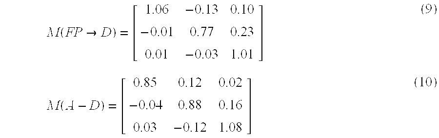
- The
storage unit 160 stores predetermined items of information according to the control from thecontrol unit 120. The information stored therein includes, among the information input to thecontrol unit 120, predetermined constants and data such as the color matching function data S, the light source spectral characteristic data L corresponding to the types of the light sources, the characteristic matrix data B, the settings on the menu screen of theoperation unit 110, the correction matrix M (WB) for white balance produced in the white balancematrix production unit 130, the information on the light source types of the image pick-up light source and observation light source determined in the light sourcetype determination unit 140, the coefficient matrix A and transformation matrix M (m→n) produced in the transformationmatrix production unit 150, and the like. It is noted that other data may also be included as the data stored therein. - The color
correction processing unit 170 performs color reproduction correction processing with respect to the image data PD1 input from the outside by using the transformation matrix produced in the transformationmatrix production unit 150, and then outputs image data PD2 as a result of color reproduction correction. The processing in the colorcorrection processing unit 170 is performed according to the control by thecontrol unit 120 based on the instructions from theoperation unit 110. This color reproduction correction processing is performed according to the transformation shown in the following equation (11).
- Here, the f (R, m), f (G, m), and f (B, m) represent R, G, and B signal components data respectively in the image data (of the light source [m]) before the color reproduction correction, while the f(R, n), f (G, n), and f (B, n) represent R, G, and B signal components data respectively in the image data (of the light source [n]) after the color reproduction correction.
- Hereinafter, the flow of processing in the color reproduction correcting method according to a first embodiment will be explained. FIG. 3 is a flow chart illustrating the flow of the processing to produce a transformation matrix in the color reproduction correcting method according to the first embodiment of the present invention. In FIG. 3, in step S 310 the
control unit 120 determines whether the estimated light source data LSD has been newly input to the white balancematrix production unit 130 and the light sourcetype determination unit 140. When it is determined that the estimated light source data LSD has been newly input, the processing proceeds to step S320. When it is determined that the data is not newly input, the processing proceeds to step S380. In step S320, thecontrol unit 120 compares the data newly input to the white balancematrix production unit 130 and light sourcetype determination unit 140 with the data input in the past and being stored in thestorage unit 160, to determine whether the newly input data is changed. When it is determined that the newly input data has been updated, the processing proceeds to step S330, while the processing proceeds to step S380 when it is determined that the data is not updated. - In step S 330, the
control unit 120 causes the newly input data to be stored in thestorage unit 160. The storage of the data may be the storage in which the past data is replaced with the newly input data. In step S340, thecontrol unit 120 determines whether the coefficient matrix A is stored in thestorage unit 160. When it is determined that the coefficient matrix A is stored in thestorage unit 160, the processing proceeds to step S350. When it is determined that the coefficient matrix A is not stored, the processing proceeds to step S360. - When it is determined in step S 340 that the coefficient matrix A is stored in the
storage unit 160, in step S350, thecontrol unit 120 takes in the coefficient matrix A from thestorage unit 160 to output it to the transformationmatrix production unit 150. When it is determined in step S340 that the coefficient matrix A is not stored, in step S360, thecontrol unit 120 receives the color matching function data S, the respective light source spectral characteristic data Lm and Ln of the image pick-up and observation light source types, the characteristic matrix data B, etc. from thestorage unit 160. Thecontrol unit 120 then calculates the matrix A according 1o the equation (2). Here, needless to say, the light source spectral characteristic data is the data regarding the light source type determined by the light sourcetype determination unit 140. Further, the produced coefficient matrix A may be stored in thestorage unit 160. - In step S 370, according to the control of the
control unit 120, the transformationmatrix production unit 150 receives the correction matrix M (WB) from the white balancematrix production unit 130. Then, using the coefficient matrix A obtained in the step S350 or step S360 and the correction matrix M (WB) for white balance, theunit 150 produces the transformation matrix M (m→n) to output it to thecontrol unit 120. Thecontrol unit 120 may store that transformation matrix M (m→n) into thestorage unit 160. Finally, in step S380, according to the predetermined items of information such as the instructions from theoperation unit 110, thecontrol unit 120 determines whether the processing should be ended. When thecontrol unit 120 determines the processing to be ended, the processing will be terminated. When thecontrol unit 120 determines the processing not to be ended, the processing proceeds to the step S310 and the above-described processing is repeated. - FIG. 4 is a flow chart illustrating the flow of the color reproduction correction processing in the color reproduction correcting method according to the first embodiment. In FIG. 4, in step S 410, the
control unit 120 performs predetermined initializations such as taking in the previously determined transformation matrix M (m→n) from thestorage unit 160. In step S420, according to the control of thecontrol unit 120, the colorcorrection processing unit 170 takes in the image data from the outside. After taking in a predetermined amount of image data, in step S430, the colorcorrection processing unit 170 performs color reproduction correction according to the above equation (8), and then outputs the color-reproduction corrected image data to the outside. - In step S 440, according to the predetermined items of information such as the instructions from the
operation unit 110, thecontrol unit 120 determines whether the processing should be ended. When thecontrol unit 120 determines the processing to be ended, the processing is terminated. When thecontrol unit 120 determines the processing not to be ended, the processing proceeds to step S450. In step S450, thecontrol unit 120 determines whether the transformationmatrix production unit 150 has produced the transformation matrix M (m→n). That may be determined according to the transformation matrix M (m→n) stored in thestorage unit 160. When it is determined that the transformation matrix M (m→n) has been updated, the processing proceeds to step S460 and then thecontrol unit 120 takes in the updated transformation matrix M (m→n) to repeat the step S420 and thereafter-succeeding processing. When it is determined that the transformation matrix M (m→n) has not been updated, the processing proceeds to step 420 to repeat step S420 and thereafter-succeeding processing. - As described above, according to the first embodiment, since the transformation matrix M (m→n) is produced in response to the observation light source or desired color rendition to correct the image data by using that transformation matrix M (m→n), it is possible to realize the color reproduction correcting method and device, capable of reproducing the colors with a desired color rendition in addition to reproducing the colors of the image excellently in the actual observation light source environment in a case where an actual observation light source environment or a desired color rendition is different from that of initially presumed.
- Further, since it has been arranged to produce the transformation matrix M (m→n) by using the predetermined number of most contributory characteristic vectors selected from among those vectors obtained by the principal component analyses thereby performing color reproduction correction, it is possible to perform the complex processing of producing the transformation matrix M (m→n) requiring a large amount of memory capacity without difficulties.
- Further, combining the color transformation technique and the white balance technique enables a processing step which produces a plurality of transformation matrixes M (m→n) under a light source of the same type to be eliminated and, therefore, it becomes possible to decrease the processing needed to produce the transformation matrixes M (m→n).
- Second Embodiment
- In the color reproduction correcting device and method therefor according to the first embodiment, the input image data is transformed into image data under a predetermined type of observation light source. However, there is also a case where such a device and method is directed to reproduce the colors of an object viewed under a light source as they are (hereinafter referred to as “the retention of the color appearance”). Specifically, there is a case where such a device and method is directed to reproduce the colors of a picked-up image as they are, even though the image was picked up under a light source with a low color rendition. For that reason, the method using transformation matrix M (m→n) in combination with the unit matrix on the basis of each being weighted is effective in the retention of the color appearance rather than the method using only a predetermined transformation matrix M (m→n). In the second embodiment, there will be described the device and method for performing color reproduction correction by a combined use of the transformation matrix M (m→n) and unit matrix on the basis of each being weighted.
- FIG. 5 is a view illustrating the entire configuration of the color
reproduction correcting device 100 according to the second embodiment, wherein a weighted transformationmatrix production unit 180 is added to the configuration illustrated in the first embodiment. - In the second embodiment, the
operation unit 110 displays predetermined settings in addition to those described in the first embodiment and waits for input on whether the weighted transformation matrix M (m→n) comp is to be produced. When that weighted transformation matrix M (m→n) comp is determined to be produced, theoperation unit 110 further waits for input on a weighting factor for every transformation matrix M (m→n). Or it is also possible to store those weighting factors in thestorage unit 160 beforehand and to cause one to be selected from among them. Further, other methods are also possible. When there is an input, the information is output to thecontrol unit 120 in which controlling each unit is performed and the information on the weighting factor for every transformation matrix M (m→n) is output to the weighted transformationmatrix production unit 180 according to that information. That weighting factor may be stored in thestorage unit 160. When it is determined that the weighted transformation matrix M (m→n) comp is to be calculated, the weighted transformationmatrix production unit 180 determines the weighting factor for each transformation matrix M (m→n) and the weighting factor for the unit matrix in the same size as the transformation matrix M. Then, the weighted transformationmatrix production unit 180 calculates a sum of the product of the transformation matrix and the weighting factor and the product of the weighted transformation matrix M (m→n) comp and the weighting factor to obtain the weighted transformation matrix M (m→n) comp, and outputs it to thecontrol unit 120 - FIG. 6 is a flow chart illustrating the flow of the processing to produce the weighted transformation matrix M (m→n) comp for use in the color reproduction correction processing in the color reproduction correcting method according to the second embodiment. Hereinafter, with reference to FIG. 6, the flow of the processing to produce the weighted transformation matrix M (m→n) comp will be explained. It is noted that the flow chart illustrating the flow of the color reproduction correction processing using that weighted transformation matrix M (m→n) comp is the same as that illustrated in FIG. 4. In the following explanation, the same processing steps as those in FIG. 3 used in the first embodiment are denoted by the same reference numerals and the explanation relevant thereto is omitted.
- In FIG. 6, in step S 601, the
control unit 120 determines whether the set weighting factor K (hereinafter referred to as “the objective factor”) is 0. When it is determined that the K is 0, the processing proceeds to step S602, and when it is determined that the K is not 0, the processing proceeds to step S310. In step S602, the weighted transformationmatrix production unit 180 sets the unit matrix as the weighted transformation matrix M (m→n) comp and outputs it to thecontrol unit 120 to end the processing it is assumed that the unit matrix is not changed in the succeeding steps of processing. - In a case where the
control unit 120 determines that the K is not 0, the processing from S310 to S360 described in the first embodiment is performed. According to the control of thecontrol unit 120, in step S670, the transformationmatrix production unit 150 receives the correction matrix M (WB) from the white balancematrix production unit 130 to produce the transformation matrix (m→n) by using the coefficient matrix A obtained in step S350 or step S360 and the correction matrix M (WB) for white balance. It is noted that, in this second embodiment, the transformation matrix M (m→n) is not output to thecontrol unit 120. Accordingly, the transformation matrix M (m→n) is not stored in thestorage unit 160. In step S671, using the above-described objective value, the weighted transformation matrix M (m→n) comp is calculated according to the following equation (12). - M(m→n)comp=K·M(m→n)+(1−K)·I (12)
- where the I is the unit matrix in the same size as that of the M (m→n) and, when K=1, there is obtained the transformation matrix K·M (m→n) for changing the light source. When K is 0, there is obtained the transformation matrix for performing the retention of the color appearance (i.e. the unit matrix I).
- Finally, according to predetermined information such as instructions from the
operation unit 110, thecontrol unit 120 determines whether to terminate the processing in step S380. When thecontrol unit 120 determines that the processing is to be ended, the processing ends. When it determines that the processing is not ended, the processing proceeds to step S310 to repeat the above-described processing. - As described above, according to this second embodiment, since the transformation matrix M (m→n) and the unit matrix are each weighted using the objective factor K, and a sum of those weighted results is calculated to produce the weighted transformation matrix M (m→n) comp, it becomes possible to cope with the user's need, as well, to retain the color appearance without changing the observation light source.
- Third Embodiment
- The color reproduction correcting method and device in the above-described first embodiment uses the characteristic matrix obtained in the principal component analyses in order to produce the transformation matrix M (m→n). Accordingly, the characteristic matrix depends upon the characteristics of the data used in the principle component analysis, and therefore when some value of bias is in the statistics of that data, it may be considered that the characteristic matrix does not excellently reflect that statistics. In such a case, to enhance the color reproducibility, it is preferable not to produce the transformation matrix using the observation data, but to produce the transformation matrix by the later described method using the data obtained by performing colorimetry on a picked-up object such as a color patch whose colors are equally distributed in a color space. A third embodiment describes the device and method for correcting the color reproduction according to the least-mean square error method on the basis of colorimetry results of the picked-up object whose colors are equally distributed in a color space.
- FIG. 7 is a view illustrating the entire configuration of the color reproduction correcting device according to the third embodiment, wherein a
correlation processing unit 190 is added to the configuration illustrated in the first embodiment. Thecorrelation processing unit 190 can be also made detachable as needed. - In this third embodiment, as above described “a picked-up object whose colors are equally distributed in a color space”, for example, a color patch is used and colorimetry is performed on CIE 13. 3 basic 8 colors, 14 colors including all colors defined under the CIE 13. 3, GretagMacbeth ColorChecker 24 colors, etc.
- The
operation unit 110 displays predetermined settings in addition to those in the first embodiment, and waits for input on whether correction using the colorimetry results on the color patch is performed. When there is an input, the information is output to thecontrol unit 120 in which control of the respective units is performed according to that information, and if necessary, thecontrol unit 120 causes a user to select a color patch or the kind of its colors, etc. required for colorimetry through theoperation unit 110. Thestorage unit 160 has stored therein beforehand the information on the color patch and the kind of the colors required for colorimetry, and outputs that information to thecorrelation processing unit 190 according to the control from thecontrol unit 120. - According to the control of the
control unit 120, thecorrelation processing unit 190 performs colorimetry on the color patch, and then produces the correlation matrix Krr of the spectral reflectance coefficient from the results obtained by colorimetry. Further, according to the following equation (15), the matrix P (A) is produced to be output to thecontrol unit 120. - The transformation
matrix production unit 150 receives the matrix P (A) through thecontrol unit 120 and produces the transformation matrix M (m→n) cor according to the following equations (13), (14), and (15). - M(m→n)cor=M(WB)(n)·Qn·[M(WB)(m)·Q(m)]−1 (13)
- Q=S T ·L·P(A) (14)
- P(A)=Krr·S·(S T ·Krr·S)−1 (15)
- The transformation matrix M (m→n) cor that has been calculated in the transformation
matrix production unit 150 is output to the colorcorrection processing unit 170 via thecontrol unit 120. In the colorcorrection processing unit 170, there is performed the color reproduction correction on the input image data by using the transformation matrix M (m→n) cor. - FIG. 8 is a flow chart illustrating the flow of the processing to produce the transformation matrix M (m→n) cor by using the colorimetry data for use in the color reproduction correction processing of the color reproduction correcting method according to the third embodiment. Hereinafter, with reference to FIG. 8, the flow of the processing to produce the transformation matrix M (m→n) cor by using the colorimetry data will be explained. The flow chart illustrating the color reproduction correction processing, using the transformation matrix M (m→n) or produced by using that colorimetry data is the same as that illustrated in FIG. 3. In the following explanation, the same processing as that of FIG. 3 used in the first embodiment is denoted with the same reference numerals and the relevant explanation thereto is omitted.
- In FIG. 8, in step S 801, the
control unit 120 determines whether the covariance matrix Krr of spectral reflectance, which was produced using the colorimetry data of the color patch, is stored in thestorage unit 160. When it is determined that the covariance matrix Krr is stored, the processing proceeds to step S310. When it is determined that the covariance matrix Krr is not stored, the processing moves to step S802. Thecorrelation processing unit 190 performs colorimetry on the color patch in step S802, and then in step S803, produces the above-described covariance matrix Krr. The covariance matrix Krr produced at this step may be stored in thestorage unit 160. Upon completion of the processing in step S803, the processing proceeds to step S310. In the steps from the step S310 and thereafter, the same processing as that in the first embodiment is performed. - In step S 340, the
control unit 120 determines whether the coefficient matrix Q is stored in thestorage unit 160. When it is determined that such matrix is not stored, in step S860 thecontrol unit 120 receives the color matching function data S, the respective light source spectral characteristic data Lm and Ln regarding the types of the image pick-up light source and the observation light source, etc. from thestorage unit 160, thereby thecontrol unit 120 calculating the matrix P (A) according to the above equation (15). Further, thecontrol unit 120, using that result, calculates the coefficient matrix Q according to the above equation (14). Needless to say, the light source spectral characteristic data is the data regarding the light source whose type is determined by the light sourcetype determination unit 140. Further, the coefficient matrix Q produced at this time may be stored in thestorage unit 160. The processing after the step S860 is the same as that described in the first embodiment. Additionally, as the method for calculating the above-described covariance matrix Krr, there is, for example, a method of calculating the covariance regarding the respective color component data on the colorimetry result of the color patch and performing transformation with respect thereto using the color matching function data S and the light source spectral characteristic data L. The method of calculating the covariance matrix Krr is known and therefore relevant explanation thereto is omitted. - As described above, according to the third embodiment, it is configured to produce the transformation matrix M (m→n) on the basis of the error least square method, using the result obtained by performing colorimetry on the picked-up object whose colors are equally distributed in a color space. Therefore, it is possible to realize the color reproduction correction which decreases errors due to the bias of the statistics.
- As described above, according to the present invention, it is configured to produce the transformation matrix M (m→n) in response to the observation light source or the desired color rendition, and to correct the image data by using that transformation matrix M (m→n). Therefore, even in a case where an actual observation light source environment or a desired color rendition is different from that initially presumed, the image can be excellently color-reproduced in the actual observation light source environment and, simultaneously, the color reproduction correcting method and device capable of color reproducing with a desired color rendition can be realized.
- Further, according to the present invention, it is configured to use the predetermined number of most contributory characteristic vectors obtained by the principal component analyses to introduce the transformation matrix M (m→n), thereby performing color reproduction correction. Therefore, it is possible to perform the complicated transformation matrix M (m→n) production processing requiring a large amount of memory capacity without difficulties.
- Further, according to the present invention, combining the color transformation technique and the white balance technique enables a processing step which produces a plurality or transformation matrixes M (m→n) under the light source of the same type to be eliminated. Therefore, it is possible to decrease steps of the processing needed to produce the transformation matrix M (m→n).
- Further, according to the present invention, it is configured to perform weighting using the objective factor K with respect to each of the transformation matrix M (m→n) and the unit matrix, and to calculate a sum of those weighted matrices to produce the weighted transformation matrix M (m→n) comp. Therefore, it becomes possible to satisfy a user's need to retain the color appearance without changing the observation light source.
- Furthermore, according to the present invention, it is configured to produce the transformation matrix M (m→n) on the basis of the error least square method using the result obtained by performing colorimetry on the picked-up object whose colors are equally distributed in a color space. Therefore, it is possible to realize the color reproduction correction capable of decreasing errors due to the bias of the statistics.
Claims (16)
Applications Claiming Priority (3)
| Application Number | Priority Date | Filing Date | Title |
|---|---|---|---|
| JP2000-332972 | 2000-10-31 | ||
| JP2000332972A JP4534340B2 (en) | 2000-10-31 | 2000-10-31 | Color reproduction correction device |
| PCT/JP2001/009113 WO2002037863A1 (en) | 2000-10-31 | 2001-10-17 | Color reproduction corrector for image input device and color reproduction correction method |
Publications (2)
| Publication Number | Publication Date |
|---|---|
| US20030113014A1 true US20030113014A1 (en) | 2003-06-19 |
| US7227571B2 US7227571B2 (en) | 2007-06-05 |
Family
ID=18809112
Family Applications (1)
| Application Number | Title | Priority Date | Filing Date |
|---|---|---|---|
| US10/169,417 Expired - Fee Related US7227571B2 (en) | 2000-10-31 | 2001-10-17 | Color reproduction corrector for image input device and color reproduction correction method |
Country Status (6)
| Country | Link |
|---|---|
| US (1) | US7227571B2 (en) |
| EP (1) | EP1331828B1 (en) |
| JP (1) | JP4534340B2 (en) |
| KR (1) | KR100843821B1 (en) |
| DE (1) | DE60138126D1 (en) |
| WO (1) | WO2002037863A1 (en) |
Cited By (44)
| Publication number | Priority date | Publication date | Assignee | Title |
|---|---|---|---|---|
| EP1578139A4 (en) * | 2002-12-25 | 2006-05-03 | Sony Corp | Image pickup device and method |
| US20060170956A1 (en) * | 2005-01-31 | 2006-08-03 | Jung Edward K | Shared image devices |
| US20060221197A1 (en) * | 2005-03-30 | 2006-10-05 | Jung Edward K | Image transformation estimator of an imaging device |
| US20060274163A1 (en) * | 2005-06-02 | 2006-12-07 | Searete Llc. | Saved-image management |
| US20070100860A1 (en) * | 2005-10-31 | 2007-05-03 | Searete Llc, A Limited Liability Corporation Of The State Of Delaware | Preservation and/or degradation of a video/audio data stream |
| US20070100533A1 (en) * | 2005-10-31 | 2007-05-03 | Searete Llc, A Limited Liability Corporation Of State Of Delaware | Preservation and/or degradation of a video/audio data stream |
| US20070097215A1 (en) * | 2005-10-31 | 2007-05-03 | Searete Llc, A Limited Liability Corporation Of The State Of Delaware | Degradation/preservation management of captured data |
| US20070120980A1 (en) * | 2005-10-31 | 2007-05-31 | Searete Llc, A Limited Liability Corporation Of The State Of Delaware | Preservation/degradation of video/audio aspects of a data stream |
| US20070168131A1 (en) * | 2006-01-19 | 2007-07-19 | Weatherbank, Inc. | Interactive advisory system |
| US20070203595A1 (en) * | 2006-02-28 | 2007-08-30 | Searete Llc, A Limited Liability Corporation | Data management of an audio data stream |
| US7782365B2 (en) | 2005-06-02 | 2010-08-24 | Searete Llc | Enhanced video/still image correlation |
| US7876357B2 (en) | 2005-01-31 | 2011-01-25 | The Invention Science Fund I, Llc | Estimating shared image device operational capabilities or resources |
| US7920169B2 (en) | 2005-01-31 | 2011-04-05 | Invention Science Fund I, Llc | Proximity of shared image devices |
| US8350946B2 (en) | 2005-01-31 | 2013-01-08 | The Invention Science Fund I, Llc | Viewfinder for shared image device |
| US8606383B2 (en) | 2005-01-31 | 2013-12-10 | The Invention Science Fund I, Llc | Audio sharing |
| US8634814B2 (en) | 2007-02-23 | 2014-01-21 | Locator IP, L.P. | Interactive advisory system for prioritizing content |
| US8681225B2 (en) | 2005-06-02 | 2014-03-25 | Royce A. Levien | Storage access technique for captured data |
| US8832121B2 (en) * | 2005-02-02 | 2014-09-09 | Accuweather, Inc. | Location-based data communications system and method |
| US8902320B2 (en) | 2005-01-31 | 2014-12-02 | The Invention Science Fund I, Llc | Shared image device synchronization or designation |
| US8909679B2 (en) | 2000-07-24 | 2014-12-09 | Locator Ip, Lp | Interactive advisory system |
| US8964054B2 (en) | 2006-08-18 | 2015-02-24 | The Invention Science Fund I, Llc | Capturing selected image objects |
| US9001215B2 (en) | 2005-06-02 | 2015-04-07 | The Invention Science Fund I, Llc | Estimating shared image device operational capabilities or resources |
| US9041826B2 (en) | 2005-06-02 | 2015-05-26 | The Invention Science Fund I, Llc | Capturing selected image objects |
| US9076208B2 (en) | 2006-02-28 | 2015-07-07 | The Invention Science Fund I, Llc | Imagery processing |
| US9082456B2 (en) | 2005-01-31 | 2015-07-14 | The Invention Science Fund I Llc | Shared image device designation |
| US9093121B2 (en) | 2006-02-28 | 2015-07-28 | The Invention Science Fund I, Llc | Data management of an audio data stream |
| US9124729B2 (en) | 2005-01-31 | 2015-09-01 | The Invention Science Fund I, Llc | Shared image device synchronization or designation |
| US9167195B2 (en) | 2005-10-31 | 2015-10-20 | Invention Science Fund I, Llc | Preservation/degradation of video/audio aspects of a data stream |
| US9191611B2 (en) | 2005-06-02 | 2015-11-17 | Invention Science Fund I, Llc | Conditional alteration of a saved image |
| US9325781B2 (en) | 2005-01-31 | 2016-04-26 | Invention Science Fund I, Llc | Audio sharing |
| US9451200B2 (en) | 2005-06-02 | 2016-09-20 | Invention Science Fund I, Llc | Storage access technique for captured data |
| US9489717B2 (en) | 2005-01-31 | 2016-11-08 | Invention Science Fund I, Llc | Shared image device |
| US9621749B2 (en) | 2005-06-02 | 2017-04-11 | Invention Science Fund I, Llc | Capturing selected image objects |
| US9819490B2 (en) | 2005-05-04 | 2017-11-14 | Invention Science Fund I, Llc | Regional proximity for shared image device(s) |
| US9910341B2 (en) | 2005-01-31 | 2018-03-06 | The Invention Science Fund I, Llc | Shared image device designation |
| US10003762B2 (en) | 2005-04-26 | 2018-06-19 | Invention Science Fund I, Llc | Shared image devices |
| US20180279866A1 (en) * | 2015-09-30 | 2018-10-04 | Hoya Corporation | Endoscope system and evaluation value calculation device |
| US10097756B2 (en) | 2005-06-02 | 2018-10-09 | Invention Science Fund I, Llc | Enhanced video/still image correlation |
| US10129484B2 (en) | 2010-09-09 | 2018-11-13 | Red.Com Llc | Optical filter opacity control for reducing temporal aliasing in motion picture capture |
| US10187588B2 (en) * | 2013-04-05 | 2019-01-22 | Red.Com, Llc | Optical filtering for electronic devices |
| US10512433B2 (en) | 2016-03-03 | 2019-12-24 | Hoya Corporation | Correction data generation method and correction data generation apparatus |
| US10646102B2 (en) * | 2016-08-31 | 2020-05-12 | Hoya Corporation | Processor for electronic endoscope, and electronic endoscope system |
| US11150378B2 (en) | 2005-01-14 | 2021-10-19 | Locator IP, L.P. | Method of outputting weather/environmental information from weather/environmental sensors |
| WO2023016320A1 (en) * | 2021-08-11 | 2023-02-16 | 维沃移动通信(杭州)有限公司 | Image processing method and apparatus, and device and medium |
Families Citing this family (10)
| Publication number | Priority date | Publication date | Assignee | Title |
|---|---|---|---|---|
| JP2004145773A (en) * | 2002-10-28 | 2004-05-20 | Japan Science & Technology Agency | Method for reproducing color of merchandise image through communication network |
| KR100848757B1 (en) * | 2004-01-29 | 2008-07-25 | 올림푸스 가부시키가이샤 | Color reproducing system and color reproducing method |
| JP5056006B2 (en) * | 2006-12-26 | 2012-10-24 | 株式会社ニコン | Imaging apparatus and program |
| JP5090146B2 (en) * | 2007-12-06 | 2012-12-05 | オリンパス株式会社 | Color conversion coefficient calculation device, color conversion coefficient calculation program, and color conversion coefficient calculation method |
| KR101536191B1 (en) | 2008-12-16 | 2015-07-13 | 삼성전자주식회사 | Apparatus and method for reproducting color |
| US8655068B1 (en) | 2011-10-07 | 2014-02-18 | LI Creative Technologies, Inc. | Color correction system |
| TWI520570B (en) * | 2012-03-19 | 2016-02-01 | 中華映管股份有限公司 | Image processing method for stereoscopic images |
| CN104766310B (en) * | 2015-03-24 | 2017-08-29 | 厦门通士达照明有限公司 | light source detection system and detection method |
| CN107801012B (en) * | 2017-10-30 | 2019-05-17 | Oppo广东移动通信有限公司 | White balancing treatment method and device, electronic device and computer readable storage medium |
| CN115835034B (en) * | 2021-09-15 | 2024-04-05 | 荣耀终端有限公司 | White balance processing method and electronic equipment |
Citations (12)
| Publication number | Priority date | Publication date | Assignee | Title |
|---|---|---|---|---|
| US6243133B1 (en) * | 1997-03-07 | 2001-06-05 | Eastman Kodak Company | Method for automatic scene balance of digital images |
| US20020008762A1 (en) * | 2000-04-28 | 2002-01-24 | Fumito Takemoto | Method, apparatus and recording medium for image processing |
| US6459449B1 (en) * | 1996-12-28 | 2002-10-01 | Nikon Corporation | Color reproduction correction device and correction method for an imaging apparatus |
| US6466334B1 (en) * | 1997-09-09 | 2002-10-15 | Olympus Optical Co., Ltd. | Color reproducing device |
| US20020196972A1 (en) * | 2001-06-26 | 2002-12-26 | Gokalp Bayramoglu | Color correction for color devices based on illuminant sensing |
| US6618079B1 (en) * | 1997-04-01 | 2003-09-09 | Sony Corporation | Color connecting apparatus for a video camera |
| US7002623B1 (en) * | 1998-09-08 | 2006-02-21 | Olympus Optical Co., Ltd. | Image processing apparatus for correcting a color and texture of an image and displaying the corrected image |
| US7002624B1 (en) * | 1999-09-01 | 2006-02-21 | Minolta Co., Ltd. | Apparatus and method for obtaining object-color component data |
| US7010161B2 (en) * | 2001-03-28 | 2006-03-07 | Seiko Epson Corporation | Image processing device, image processing method, and computer readable medium storing program for image color correction with priority to one of color reproduction and brightness |
| US7061646B2 (en) * | 2000-10-23 | 2006-06-13 | Seiko Epson Corporation | Color correction table generating method, image processing device, image processing method and recording media |
| US7146041B2 (en) * | 2001-11-08 | 2006-12-05 | Fuji Photo Film Co., Ltd. | Method and apparatus for correcting white balance, method for correcting density and recording medium on which program for carrying out the methods is recorded |
| US7158174B2 (en) * | 2002-04-04 | 2007-01-02 | Eastman Kodak Company | Method for automatic white balance of digital images |
Family Cites Families (17)
| Publication number | Priority date | Publication date | Assignee | Title |
|---|---|---|---|---|
| JP2874235B2 (en) * | 1990-01-12 | 1999-03-24 | 日本電気株式会社 | Color measurement method |
| JP3253334B2 (en) * | 1992-01-16 | 2002-02-04 | 三洋電機株式会社 | White balance correction device |
| JPH0628437A (en) * | 1992-07-07 | 1994-02-04 | Seiko Instr Inc | Image input/output device |
| JPH0730916A (en) * | 1993-07-09 | 1995-01-31 | Nec Corp | Color reproduction correction circuit for color image pickup device |
| JP3149297B2 (en) * | 1993-08-25 | 2001-03-26 | 東洋インキ製造株式会社 | Color balance adjustment device and adjustment method |
| JPH09163382A (en) * | 1995-12-07 | 1997-06-20 | Toyo Ink Mfg Co Ltd | Color slurring correction method and device |
| JP3679488B2 (en) * | 1996-01-31 | 2005-08-03 | キヤノン株式会社 | Image processing apparatus and method |
| JPH09215000A (en) * | 1996-02-01 | 1997-08-15 | Canon Inc | Image pickup device and image signal processing method |
| JP3304740B2 (en) * | 1996-02-20 | 2002-07-22 | 東洋インキ製造株式会社 | Color simulation device |
| JPH09284581A (en) * | 1996-04-15 | 1997-10-31 | Toyo Ink Mfg Co Ltd | Color simulation device |
| JP3829363B2 (en) * | 1996-06-14 | 2006-10-04 | コニカミノルタホールディングス株式会社 | Electronic camera |
| JPH10108031A (en) * | 1996-10-01 | 1998-04-24 | Canon Inc | Device and method for processing image and recording medium |
| JPH10173941A (en) * | 1996-12-16 | 1998-06-26 | Toyo Ink Mfg Co Ltd | Method and device for correcting color smear of natural image |
| JP3887060B2 (en) * | 1997-04-09 | 2007-02-28 | ペンタックス株式会社 | Image correction information recording apparatus and image restoration processing apparatus for electronic still camera |
| DE69835638T2 (en) | 1997-07-09 | 2006-12-28 | Canon K.K. | Color image processing apparatus and method |
| JP3639696B2 (en) * | 1997-07-09 | 2005-04-20 | キヤノン株式会社 | Image processing method and apparatus, and storage medium |
| JP3305265B2 (en) * | 1998-07-24 | 2002-07-22 | キヤノン株式会社 | Image processing apparatus and method |
-
2000
- 2000-10-31 JP JP2000332972A patent/JP4534340B2/en not_active Expired - Fee Related
-
2001
- 2001-10-17 DE DE60138126T patent/DE60138126D1/en not_active Expired - Lifetime
- 2001-10-17 EP EP01978819A patent/EP1331828B1/en not_active Expired - Lifetime
- 2001-10-17 US US10/169,417 patent/US7227571B2/en not_active Expired - Fee Related
- 2001-10-17 WO PCT/JP2001/009113 patent/WO2002037863A1/en active Application Filing
- 2001-10-17 KR KR1020027008589A patent/KR100843821B1/en not_active IP Right Cessation
Patent Citations (12)
| Publication number | Priority date | Publication date | Assignee | Title |
|---|---|---|---|---|
| US6459449B1 (en) * | 1996-12-28 | 2002-10-01 | Nikon Corporation | Color reproduction correction device and correction method for an imaging apparatus |
| US6243133B1 (en) * | 1997-03-07 | 2001-06-05 | Eastman Kodak Company | Method for automatic scene balance of digital images |
| US6618079B1 (en) * | 1997-04-01 | 2003-09-09 | Sony Corporation | Color connecting apparatus for a video camera |
| US6466334B1 (en) * | 1997-09-09 | 2002-10-15 | Olympus Optical Co., Ltd. | Color reproducing device |
| US7002623B1 (en) * | 1998-09-08 | 2006-02-21 | Olympus Optical Co., Ltd. | Image processing apparatus for correcting a color and texture of an image and displaying the corrected image |
| US7002624B1 (en) * | 1999-09-01 | 2006-02-21 | Minolta Co., Ltd. | Apparatus and method for obtaining object-color component data |
| US20020008762A1 (en) * | 2000-04-28 | 2002-01-24 | Fumito Takemoto | Method, apparatus and recording medium for image processing |
| US7061646B2 (en) * | 2000-10-23 | 2006-06-13 | Seiko Epson Corporation | Color correction table generating method, image processing device, image processing method and recording media |
| US7010161B2 (en) * | 2001-03-28 | 2006-03-07 | Seiko Epson Corporation | Image processing device, image processing method, and computer readable medium storing program for image color correction with priority to one of color reproduction and brightness |
| US20020196972A1 (en) * | 2001-06-26 | 2002-12-26 | Gokalp Bayramoglu | Color correction for color devices based on illuminant sensing |
| US7146041B2 (en) * | 2001-11-08 | 2006-12-05 | Fuji Photo Film Co., Ltd. | Method and apparatus for correcting white balance, method for correcting density and recording medium on which program for carrying out the methods is recorded |
| US7158174B2 (en) * | 2002-04-04 | 2007-01-02 | Eastman Kodak Company | Method for automatic white balance of digital images |
Cited By (76)
| Publication number | Priority date | Publication date | Assignee | Title |
|---|---|---|---|---|
| US9998295B2 (en) | 2000-07-24 | 2018-06-12 | Locator IP, L.P. | Interactive advisory system |
| US9668091B2 (en) | 2000-07-24 | 2017-05-30 | Locator IP, L.P. | Interactive weather advisory system |
| US8909679B2 (en) | 2000-07-24 | 2014-12-09 | Locator Ip, Lp | Interactive advisory system |
| US9204252B2 (en) | 2000-07-24 | 2015-12-01 | Locator IP, L.P. | Interactive advisory system |
| US10411908B2 (en) | 2000-07-24 | 2019-09-10 | Locator IP, L.P. | Interactive advisory system |
| US11108582B2 (en) | 2000-07-24 | 2021-08-31 | Locator IP, L.P. | Interactive weather advisory system |
| US9661457B2 (en) | 2000-07-24 | 2017-05-23 | Locator Ip, Lp | Interactive advisory system |
| US9197990B2 (en) | 2000-07-24 | 2015-11-24 | Locator Ip, Lp | Interactive advisory system |
| US10021525B2 (en) | 2000-07-24 | 2018-07-10 | Locator IP, L.P. | Interactive weather advisory system |
| US9554246B2 (en) | 2000-07-24 | 2017-01-24 | Locator Ip, Lp | Interactive weather advisory system |
| US9560480B2 (en) | 2000-07-24 | 2017-01-31 | Locator Ip, Lp | Interactive advisory system |
| US9191776B2 (en) | 2000-07-24 | 2015-11-17 | Locator Ip, Lp | Interactive advisory system |
| EP1578139A4 (en) * | 2002-12-25 | 2006-05-03 | Sony Corp | Image pickup device and method |
| US11150378B2 (en) | 2005-01-14 | 2021-10-19 | Locator IP, L.P. | Method of outputting weather/environmental information from weather/environmental sensors |
| US9082456B2 (en) | 2005-01-31 | 2015-07-14 | The Invention Science Fund I Llc | Shared image device designation |
| US8902320B2 (en) | 2005-01-31 | 2014-12-02 | The Invention Science Fund I, Llc | Shared image device synchronization or designation |
| US9124729B2 (en) | 2005-01-31 | 2015-09-01 | The Invention Science Fund I, Llc | Shared image device synchronization or designation |
| US9489717B2 (en) | 2005-01-31 | 2016-11-08 | Invention Science Fund I, Llc | Shared image device |
| US7876357B2 (en) | 2005-01-31 | 2011-01-25 | The Invention Science Fund I, Llc | Estimating shared image device operational capabilities or resources |
| US9910341B2 (en) | 2005-01-31 | 2018-03-06 | The Invention Science Fund I, Llc | Shared image device designation |
| US8350946B2 (en) | 2005-01-31 | 2013-01-08 | The Invention Science Fund I, Llc | Viewfinder for shared image device |
| US8606383B2 (en) | 2005-01-31 | 2013-12-10 | The Invention Science Fund I, Llc | Audio sharing |
| US9325781B2 (en) | 2005-01-31 | 2016-04-26 | Invention Science Fund I, Llc | Audio sharing |
| US8988537B2 (en) | 2005-01-31 | 2015-03-24 | The Invention Science Fund I, Llc | Shared image devices |
| US7920169B2 (en) | 2005-01-31 | 2011-04-05 | Invention Science Fund I, Llc | Proximity of shared image devices |
| US9019383B2 (en) | 2005-01-31 | 2015-04-28 | The Invention Science Fund I, Llc | Shared image devices |
| US20060170956A1 (en) * | 2005-01-31 | 2006-08-03 | Jung Edward K | Shared image devices |
| US8832121B2 (en) * | 2005-02-02 | 2014-09-09 | Accuweather, Inc. | Location-based data communications system and method |
| US20060221197A1 (en) * | 2005-03-30 | 2006-10-05 | Jung Edward K | Image transformation estimator of an imaging device |
| US20080088713A1 (en) * | 2005-03-30 | 2008-04-17 | Searete LLC, a liability corporation of the State of Delaware | Image transformation estimator of an imaging device |
| US20090027546A1 (en) * | 2005-03-30 | 2009-01-29 | Searete Llc,A Limited Liability Corporation | Image transformation estimator of an imaging device |
| US10003762B2 (en) | 2005-04-26 | 2018-06-19 | Invention Science Fund I, Llc | Shared image devices |
| US9819490B2 (en) | 2005-05-04 | 2017-11-14 | Invention Science Fund I, Llc | Regional proximity for shared image device(s) |
| US9041826B2 (en) | 2005-06-02 | 2015-05-26 | The Invention Science Fund I, Llc | Capturing selected image objects |
| US9001215B2 (en) | 2005-06-02 | 2015-04-07 | The Invention Science Fund I, Llc | Estimating shared image device operational capabilities or resources |
| US9621749B2 (en) | 2005-06-02 | 2017-04-11 | Invention Science Fund I, Llc | Capturing selected image objects |
| US8681225B2 (en) | 2005-06-02 | 2014-03-25 | Royce A. Levien | Storage access technique for captured data |
| US9967424B2 (en) | 2005-06-02 | 2018-05-08 | Invention Science Fund I, Llc | Data storage usage protocol |
| US7872675B2 (en) | 2005-06-02 | 2011-01-18 | The Invention Science Fund I, Llc | Saved-image management |
| US9451200B2 (en) | 2005-06-02 | 2016-09-20 | Invention Science Fund I, Llc | Storage access technique for captured data |
| US7782365B2 (en) | 2005-06-02 | 2010-08-24 | Searete Llc | Enhanced video/still image correlation |
| US9191611B2 (en) | 2005-06-02 | 2015-11-17 | Invention Science Fund I, Llc | Conditional alteration of a saved image |
| US10097756B2 (en) | 2005-06-02 | 2018-10-09 | Invention Science Fund I, Llc | Enhanced video/still image correlation |
| US20060274163A1 (en) * | 2005-06-02 | 2006-12-07 | Searete Llc. | Saved-image management |
| US8233042B2 (en) | 2005-10-31 | 2012-07-31 | The Invention Science Fund I, Llc | Preservation and/or degradation of a video/audio data stream |
| US20070097215A1 (en) * | 2005-10-31 | 2007-05-03 | Searete Llc, A Limited Liability Corporation Of The State Of Delaware | Degradation/preservation management of captured data |
| US20070100860A1 (en) * | 2005-10-31 | 2007-05-03 | Searete Llc, A Limited Liability Corporation Of The State Of Delaware | Preservation and/or degradation of a video/audio data stream |
| US8072501B2 (en) | 2005-10-31 | 2011-12-06 | The Invention Science Fund I, Llc | Preservation and/or degradation of a video/audio data stream |
| US9167195B2 (en) | 2005-10-31 | 2015-10-20 | Invention Science Fund I, Llc | Preservation/degradation of video/audio aspects of a data stream |
| US20070100533A1 (en) * | 2005-10-31 | 2007-05-03 | Searete Llc, A Limited Liability Corporation Of State Of Delaware | Preservation and/or degradation of a video/audio data stream |
| US8253821B2 (en) | 2005-10-31 | 2012-08-28 | The Invention Science Fund I, Llc | Degradation/preservation management of captured data |
| US20070120980A1 (en) * | 2005-10-31 | 2007-05-31 | Searete Llc, A Limited Liability Corporation Of The State Of Delaware | Preservation/degradation of video/audio aspects of a data stream |
| US8804033B2 (en) | 2005-10-31 | 2014-08-12 | The Invention Science Fund I, Llc | Preservation/degradation of video/audio aspects of a data stream |
| US10362435B2 (en) | 2006-01-19 | 2019-07-23 | Locator IP, L.P. | Interactive advisory system |
| US20070168131A1 (en) * | 2006-01-19 | 2007-07-19 | Weatherbank, Inc. | Interactive advisory system |
| US8611927B2 (en) | 2006-01-19 | 2013-12-17 | Locator Ip, Lp | Interactive advisory system |
| US9094798B2 (en) | 2006-01-19 | 2015-07-28 | Locator IP, L.P. | Interactive advisory system |
| US8229467B2 (en) | 2006-01-19 | 2012-07-24 | Locator IP, L.P. | Interactive advisory system |
| US9210541B2 (en) | 2006-01-19 | 2015-12-08 | Locator IP, L.P. | Interactive advisory system |
| US9215554B2 (en) | 2006-01-19 | 2015-12-15 | Locator IP, L.P. | Interactive advisory system |
| US20070203595A1 (en) * | 2006-02-28 | 2007-08-30 | Searete Llc, A Limited Liability Corporation | Data management of an audio data stream |
| US9093121B2 (en) | 2006-02-28 | 2015-07-28 | The Invention Science Fund I, Llc | Data management of an audio data stream |
| US9076208B2 (en) | 2006-02-28 | 2015-07-07 | The Invention Science Fund I, Llc | Imagery processing |
| US8964054B2 (en) | 2006-08-18 | 2015-02-24 | The Invention Science Fund I, Llc | Capturing selected image objects |
| US10616708B2 (en) | 2007-02-23 | 2020-04-07 | Locator Ip, Lp | Interactive advisory system for prioritizing content |
| US9237416B2 (en) | 2007-02-23 | 2016-01-12 | Locator IP, L.P. | Interactive advisory system for prioritizing content |
| US8634814B2 (en) | 2007-02-23 | 2014-01-21 | Locator IP, L.P. | Interactive advisory system for prioritizing content |
| US10021514B2 (en) | 2007-02-23 | 2018-07-10 | Locator IP, L.P. | Interactive advisory system for prioritizing content |
| US10129484B2 (en) | 2010-09-09 | 2018-11-13 | Red.Com Llc | Optical filter opacity control for reducing temporal aliasing in motion picture capture |
| US10630908B2 (en) | 2010-09-09 | 2020-04-21 | Red.Com, Llc | Optical filter opacity control in motion picture capture |
| US10187588B2 (en) * | 2013-04-05 | 2019-01-22 | Red.Com, Llc | Optical filtering for electronic devices |
| US10918270B2 (en) * | 2015-09-30 | 2021-02-16 | Hoya Corporation | Endoscope system and evaluation value calculation device |
| US20180279866A1 (en) * | 2015-09-30 | 2018-10-04 | Hoya Corporation | Endoscope system and evaluation value calculation device |
| US10512433B2 (en) | 2016-03-03 | 2019-12-24 | Hoya Corporation | Correction data generation method and correction data generation apparatus |
| US10646102B2 (en) * | 2016-08-31 | 2020-05-12 | Hoya Corporation | Processor for electronic endoscope, and electronic endoscope system |
| WO2023016320A1 (en) * | 2021-08-11 | 2023-02-16 | 维沃移动通信(杭州)有限公司 | Image processing method and apparatus, and device and medium |
Also Published As
| Publication number | Publication date |
|---|---|
| KR20020067587A (en) | 2002-08-22 |
| JP4534340B2 (en) | 2010-09-01 |
| DE60138126D1 (en) | 2009-05-07 |
| EP1331828A1 (en) | 2003-07-30 |
| KR100843821B1 (en) | 2008-07-04 |
| WO2002037863A1 (en) | 2002-05-10 |
| US7227571B2 (en) | 2007-06-05 |
| JP2002142231A (en) | 2002-05-17 |
| EP1331828A4 (en) | 2006-04-19 |
| EP1331828B1 (en) | 2009-03-25 |
Similar Documents
| Publication | Publication Date | Title |
|---|---|---|
| US7227571B2 (en) | Color reproduction corrector for image input device and color reproduction correction method | |
| JP3008878B2 (en) | Color conversion method and apparatus, and machine-readable recording medium recording program | |
| US7180629B1 (en) | Methods and apparatus for color device characterization | |
| CN1956551B (en) | Image processing method, image processing apparatus, imaging apparatus, imaging method | |
| US7868937B2 (en) | Imaging apparatus and imaging device | |
| US20080080767A1 (en) | Method and apparatus for performing gamut mapping between heterogeneous devices | |
| US7561167B2 (en) | Image processing apparatus and image processing method | |
| US20080204469A1 (en) | Color Transformation Luminance Correction Method and Device | |
| US20030214510A1 (en) | Projection plane color correction method of projector, projection plane color correction system of projector and program for projection plane color correction of projector | |
| US8805060B2 (en) | Color conversion device, image output device, and color conversion method | |
| US7127102B2 (en) | Color matching method and device, color matching program, and computer readable record medium that stores color matching program allowing appropriate color matching at high speed | |
| US8531548B2 (en) | Image processing method, image processing program, image processing device and camera | |
| KR20060118827A (en) | Apparatus and method for compensating color of video signal in a display device | |
| US20080013827A1 (en) | Method of Electronic Color Image Saturation Processing | |
| CN113170028A (en) | Method for generating image data of imaging algorithm based on machine learning | |
| US7583303B2 (en) | Imaging device element | |
| WO2006020632A2 (en) | Digital color fidelity | |
| US20030164828A1 (en) | Image processing method, apparatus and system, evaluation method for photographing apparatus, image data storage method, and data structure of image data file | |
| US6507667B1 (en) | Color digital imaging apparatus having a rule-based hue-shift processor | |
| US7852380B2 (en) | Signal processing system and method of operation for nonlinear signal processing | |
| Le et al. | Gamutnet: Restoring wide-gamut colors for camera-captured images | |
| CN101019131B (en) | System and method for effectively performing an image data transformation procedure | |
| US7015980B2 (en) | Color temperature conversion apparatus in color display system and method thereof | |
| EP0526989A2 (en) | Display control device | |
| JP2003179946A (en) | Chromaticity correcting equipment |
Legal Events
| Date | Code | Title | Description |
|---|---|---|---|
| AS | Assignment |
Owner name: SONY CORPORATION, JAPAN Free format text: ASSIGNMENT OF ASSIGNORS INTEREST;ASSIGNOR:KATOH, NAOYA;REEL/FRAME:013482/0813 Effective date: 20021010 |
|
| STCF | Information on status: patent grant |
Free format text: PATENTED CASE |
|
| FEPP | Fee payment procedure |
Free format text: PAYOR NUMBER ASSIGNED (ORIGINAL EVENT CODE: ASPN); ENTITY STATUS OF PATENT OWNER: LARGE ENTITY |
|
| FPAY | Fee payment |
Year of fee payment: 4 |
|
| FPAY | Fee payment |
Year of fee payment: 8 |
|
| FEPP | Fee payment procedure |
Free format text: MAINTENANCE FEE REMINDER MAILED (ORIGINAL EVENT CODE: REM.); ENTITY STATUS OF PATENT OWNER: LARGE ENTITY |
|
| LAPS | Lapse for failure to pay maintenance fees |
Free format text: PATENT EXPIRED FOR FAILURE TO PAY MAINTENANCE FEES (ORIGINAL EVENT CODE: EXP.); ENTITY STATUS OF PATENT OWNER: LARGE ENTITY |
|
| STCH | Information on status: patent discontinuation |
Free format text: PATENT EXPIRED DUE TO NONPAYMENT OF MAINTENANCE FEES UNDER 37 CFR 1.362 |
|
| FP | Lapsed due to failure to pay maintenance fee |
Effective date: 20190605 |