US20030190582A1 - Dental facility having changeable dental tools - Google Patents
Dental facility having changeable dental tools Download PDFInfo
- Publication number
- US20030190582A1 US20030190582A1 US10/122,249 US12224902A US2003190582A1 US 20030190582 A1 US20030190582 A1 US 20030190582A1 US 12224902 A US12224902 A US 12224902A US 2003190582 A1 US2003190582 A1 US 2003190582A1
- Authority
- US
- United States
- Prior art keywords
- coupler
- dental
- latch
- barrel
- shank
- Prior art date
- Legal status (The legal status is an assumption and is not a legal conclusion. Google has not performed a legal analysis and makes no representation as to the accuracy of the status listed.)
- Abandoned
Links
Images


Classifications
-
- A—HUMAN NECESSITIES
- A61—MEDICAL OR VETERINARY SCIENCE; HYGIENE
- A61C—DENTISTRY; APPARATUS OR METHODS FOR ORAL OR DENTAL HYGIENE
- A61C1/00—Dental machines for boring or cutting ; General features of dental machines or apparatus, e.g. hand-piece design
- A61C1/08—Machine parts specially adapted for dentistry
Definitions
- the present invention relates to a dental facility, and more particularly to a dental facility having changeable dental tool members.
- Typical dental facilities comprise such as the dental burs, which includes a bur head or bur tool attached to one end of a handle, for engaging into the mouths of the users and for working onto the teeth.
- the typical dental facilities may further include a spraying device having a sprayer head attached to one end of a handle, also for engaging into and for spraying water into the mouths of the users, and/or for working onto the teeth of the users.
- the dental tool members such as the bur heads or bur tools, or the sprayer heads, are solidly secured to the handle and may not be disengaged from the handle, such that the dental tool members may only be flushed or cleaned with water or detergent after every working or operation.
- AIDS has become a serious problem to both the dentists and the patients, because the AIDS viruses may be contaminated or infected via the dental tool members that have not been completely cleaned, and that may not be fully and completely cleaned.
- the present invention has arisen to mitigate and/or obviate the afore-described disadvantages of the conventional dental facilities.
- the primary objective of the present invention is to provide a dental facility including a dental tool member that may be easily disengaged or removed from the handle, and that may be discarded after use, and that may be quickly changed with the other ones after use.
- a dental facility comprising a coupler including an upper portion, a latch disposed in the coupler, and including a tongue extendible outward of the coupler, a dental tool member including a barrel engageable onto the upper portion of the coupler, and means for biasing the tongue of the latch to engage with the barrel and to detachably secure the dental tool member to the coupler.
- the dental tool member is allowed to be detached from the coupler for being changed with the other one after use, and for preventing both the patients and the dentists from being contaminated or infected with various viruses by the dental tool member.
- the coupler includes a shank disposed in the upper portion of the coupler and having an upper portion extended upward beyond the coupler, the shank includes a channel formed therein for receiving the latch.
- the shank includes an aperture formed therein and communicating with the channel of the shank, and a rod engaged through the aperture of the shank and engaged through the latch for pivotally securing the latch to the shank.
- the shank includes a cavity formed therein
- the biasing means includes a spring received in the cavity of the shank and engaged with the latch for biasing the tongue of the latch to engage with the barrel of the dental tool member.
- the barrel includes a hole formed therein.
- a device may further be provided for disengaging the tongue of the latch from the barrel of the dental tool member, and includes a knob slidably engaged in the hole of the barrel and engaged with the latch for depressing the latch against the biasing means and for disengaging the tongue of the latch from the barrel of the dental tool member.
- the knob includes an inner end located with the barrel and having an enlarged head provided thereon for engaging with the barrel and for preventing the knob from being disengaged from the barrel.
- a duct is further provided and secured to the coupler, and a handle is further provided and attached to the duct.
- the duct includes a bent upper portion secured to the lower portion of the coupler.
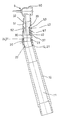
- FIG. 1 is a perspective view of a dental facility in accordance with the present invention.
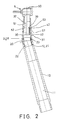
- FIG. 2 is a cross sectional view taken along lines 2 - 2 of FIG. 1;
- FIG. 3 is a cross sectional and exploded view of the dental facility.
- FIG. 4 is an end view illustrating the coupler of the dental facility for quickly coupling the dental tool member.
- a dental facility in accordance with the present invention comprises a handle 10 including a bore 11 formed therein and including one end, such as the lower end thereof for coupling to the water and/or medicine reservoir, for receiving the water and/or the medicine therefrom.
- the handle 10 includes an inner thread 12 formed in the other end thereof, such as the upper end thereof.
- a duct 20 includes an outer thread 21 formed or provided on the outer peripheral portion of the lower portion thereof for threading with the inner thread 12 of the handle 10 , and for coupling the duct 20 to the handle 10 .
- the duct 20 includes a bore 22 formed therein for communicating with the bore 11 of the handle 10 and for receiving the water and/or the medicine from the handle 10 .
- the duct 20 includes a bent portion 23 formed or provided on the upper portion thereof and having an outer thread 24 formed or provided on the outer peripheral portion thereof.
- a coupler 30 includes an inner thread 31 formed or provided in the lower portion thereof for threading with the outer thread 24 of the duct 20 , and for attaching the coupler 30 to the duct 20 .
- the coupler 30 may also be directly secured to the handle 10 , instead of to the duct 20 .
- the coupler 30 includes a shank 32 secured in the upper portion thereof with such as fasteners, or adhesive materials, or by welding processes.
- the shank 32 has an upper portion partially extended upward and outward beyond the coupler 30 , and includes one or more passages 33 formed therein (FIG. 4) for communicating with the bores 11 , 22 of the handle 10 and the duct 20 and for receiving the water and/or the medicine from the duct 20 and the handle 10 .
- the coupler 30 includes a channel 34 formed therein, such as formed in the shank 32 , and an aperture 35 formed in the lower portion of the shank 32 and communicating with the lower portion of the channel 34 thereof for receiving a rod 37 therein, and a cavity 38 formed in the shank 32 and communicating with the upper portion of the channel 34 of the coupler 30 for receiving a spring 39 therein.
- a latch 40 is received in the channel 34 of the coupler 30 , and includes an orifice 41 formed therein, such as formed in the lower portion thereof for receiving the rod 37 and for rotatably securing the lower portion of the latch 40 to the shank 32 or to the coupler 30 .
- the latch 40 includes a tongue 42 provided or bent or formed on the upper portion thereof and extended away from the shank 32 or the coupler 30 .
- the spring 39 may engage with the latch 40 and thus may bias the tongue 42 of the latch 40 outward or away from the shank 32 or the coupler 30 .
- a dental tool member 5 such as a bur head 50 , provided on the upper portion of a barrel 51 for engaging into the mouths of the uses and for working onto the teeth of the users.
- the barrel 51 includes a bore 52 formed therein for receiving the upper portion of the shank 32 or of the coupler 30 , and includes an opening 53 formed therein for selectively or detachably receiving the tongue 42 of the latch 40 and for detachably securing the barrel 51 and the bur head 50 of the dental tool member 5 to the coupler 30 .
- the tongue 42 of the latch 40 may be moved inward of the channel 34 of the shank 32 or of the coupler 30 when the upper portion of the shank 32 or of the coupler 30 is engaged into the bore 52 of the barrel 51 , for allowing the tongue 42 of the latch 40 to be biased and engaged into the opening 53 of the barrel 51 when the tongue 42 of the latch 40 is aligned with the opening 53 of the barrel 51 , such that the dental tool member 5 may be easily and quickly secured onto the coupler 30 with the latch 40 .
- the barrel 51 further includes a hole 54 formed therein, such as located below the opening 53 of the barrel 51 .
- a button or a knob 57 is slidably received in the hole 54 of the barrel 51 , and includes an enlarged head 58 formed on one end thereof, such as the inner end thereof, and received in the barrel 51 , for preventing the knob 57 from being disengaged from the barrel 51 .
- the inner end of the knob 57 is engaged with the latch 40 for depressing the latch 40 against the spring 39 , and for disengaging the tongue 42 of the latch 40 from the barrel 51 , and for allowing the dental tool member 5 to be easily and quickly disengaged from the coupler 30 , and for allowing the dental tool member 5 to be easily and quickly discarded or replaced with the other ones.
- the dental tool member 5 may be easily and quickly disengaged from the coupler 30 , and may thus be discarded after each or every use.
- the other dental tool members 5 may then be easily and quickly secured or attached onto the coupler 30 for engaging with or for working onto the teeth of the other users. The patients thus will not be infected with the AIDS or the other viruses by the dental tool member 5 .
- the dental facility in accordance with the present invention includes a dental tool member that may be easily disengaged or removed from the handle, and that may be discarded after use, and that may be quickly changed with the other ones after use.
Abstract
A dental facility includes a latch disposed in a coupler and having a tongue extendible outward of the coupler, a dental tool member having a barrel engageable onto the coupler, and a spring for biasing the tongue of the latch to engage with the barrel and to detachably secure the dental tool member to the coupler. The dental tool member may be detached from the coupler for being discarded or changed with the other one after use, and for preventing both the patients and the dentists from being contaminated or infected by the dental tool member.
Description
- 1. Field of the Invention
- The present invention relates to a dental facility, and more particularly to a dental facility having changeable dental tool members.
- 2. Description of the Prior Art
- Typical dental facilities comprise such as the dental burs, which includes a bur head or bur tool attached to one end of a handle, for engaging into the mouths of the users and for working onto the teeth. The typical dental facilities may further include a spraying device having a sprayer head attached to one end of a handle, also for engaging into and for spraying water into the mouths of the users, and/or for working onto the teeth of the users. The dental tool members, such as the bur heads or bur tools, or the sprayer heads, are solidly secured to the handle and may not be disengaged from the handle, such that the dental tool members may only be flushed or cleaned with water or detergent after every working or operation.
- However, AIDS has become a serious problem to both the dentists and the patients, because the AIDS viruses may be contaminated or infected via the dental tool members that have not been completely cleaned, and that may not be fully and completely cleaned.
- The present invention has arisen to mitigate and/or obviate the afore-described disadvantages of the conventional dental facilities.
- The primary objective of the present invention is to provide a dental facility including a dental tool member that may be easily disengaged or removed from the handle, and that may be discarded after use, and that may be quickly changed with the other ones after use.
- In accordance with one aspect of the invention, there is provided a dental facility comprising a coupler including an upper portion, a latch disposed in the coupler, and including a tongue extendible outward of the coupler, a dental tool member including a barrel engageable onto the upper portion of the coupler, and means for biasing the tongue of the latch to engage with the barrel and to detachably secure the dental tool member to the coupler. The dental tool member is allowed to be detached from the coupler for being changed with the other one after use, and for preventing both the patients and the dentists from being contaminated or infected with various viruses by the dental tool member.
- The coupler includes a shank disposed in the upper portion of the coupler and having an upper portion extended upward beyond the coupler, the shank includes a channel formed therein for receiving the latch.
- The shank includes an aperture formed therein and communicating with the channel of the shank, and a rod engaged through the aperture of the shank and engaged through the latch for pivotally securing the latch to the shank.
- The shank includes a cavity formed therein, the biasing means includes a spring received in the cavity of the shank and engaged with the latch for biasing the tongue of the latch to engage with the barrel of the dental tool member.
- The barrel includes a hole formed therein. A device may further be provided for disengaging the tongue of the latch from the barrel of the dental tool member, and includes a knob slidably engaged in the hole of the barrel and engaged with the latch for depressing the latch against the biasing means and for disengaging the tongue of the latch from the barrel of the dental tool member.
- The knob includes an inner end located with the barrel and having an enlarged head provided thereon for engaging with the barrel and for preventing the knob from being disengaged from the barrel.
- A duct is further provided and secured to the coupler, and a handle is further provided and attached to the duct. The duct includes a bent upper portion secured to the lower portion of the coupler.
- Further objectives and advantages of the present invention will become apparent from a careful reading of a detailed description provided hereinbelow, with appropriate reference to accompanying drawings.
- FIG. 1 is a perspective view of a dental facility in accordance with the present invention;
- FIG. 2 is a cross sectional view taken along lines 2-2 of FIG. 1;
- FIG. 3 is a cross sectional and exploded view of the dental facility; and
- FIG. 4 is an end view illustrating the coupler of the dental facility for quickly coupling the dental tool member.
- Referring to the drawings, and initially to FIGS. 1-3, a dental facility in accordance with the present invention comprises a
handle 10 including abore 11 formed therein and including one end, such as the lower end thereof for coupling to the water and/or medicine reservoir, for receiving the water and/or the medicine therefrom. Thehandle 10 includes aninner thread 12 formed in the other end thereof, such as the upper end thereof. - A
duct 20 includes anouter thread 21 formed or provided on the outer peripheral portion of the lower portion thereof for threading with theinner thread 12 of thehandle 10, and for coupling theduct 20 to thehandle 10. Theduct 20 includes abore 22 formed therein for communicating with thebore 11 of thehandle 10 and for receiving the water and/or the medicine from thehandle 10. Theduct 20 includes abent portion 23 formed or provided on the upper portion thereof and having anouter thread 24 formed or provided on the outer peripheral portion thereof. - A
coupler 30 includes aninner thread 31 formed or provided in the lower portion thereof for threading with theouter thread 24 of theduct 20, and for attaching thecoupler 30 to theduct 20. Alternatively, thecoupler 30 may also be directly secured to thehandle 10, instead of to theduct 20. Thecoupler 30 includes ashank 32 secured in the upper portion thereof with such as fasteners, or adhesive materials, or by welding processes. Theshank 32 has an upper portion partially extended upward and outward beyond thecoupler 30, and includes one ormore passages 33 formed therein (FIG. 4) for communicating with thebores handle 10 and theduct 20 and for receiving the water and/or the medicine from theduct 20 and thehandle 10. - The
coupler 30 includes achannel 34 formed therein, such as formed in theshank 32, and anaperture 35 formed in the lower portion of theshank 32 and communicating with the lower portion of thechannel 34 thereof for receiving arod 37 therein, and acavity 38 formed in theshank 32 and communicating with the upper portion of thechannel 34 of thecoupler 30 for receiving aspring 39 therein. - A
latch 40 is received in thechannel 34 of thecoupler 30, and includes anorifice 41 formed therein, such as formed in the lower portion thereof for receiving therod 37 and for rotatably securing the lower portion of thelatch 40 to theshank 32 or to thecoupler 30. Thelatch 40 includes atongue 42 provided or bent or formed on the upper portion thereof and extended away from theshank 32 or thecoupler 30. Thespring 39 may engage with thelatch 40 and thus may bias thetongue 42 of thelatch 40 outward or away from theshank 32 or thecoupler 30. - A
dental tool member 5, such as abur head 50, provided on the upper portion of abarrel 51 for engaging into the mouths of the uses and for working onto the teeth of the users. Thebarrel 51 includes abore 52 formed therein for receiving the upper portion of theshank 32 or of thecoupler 30, and includes anopening 53 formed therein for selectively or detachably receiving thetongue 42 of thelatch 40 and for detachably securing thebarrel 51 and thebur head 50 of thedental tool member 5 to thecoupler 30. - It is to be noted that the
tongue 42 of thelatch 40 may be moved inward of thechannel 34 of theshank 32 or of thecoupler 30 when the upper portion of theshank 32 or of thecoupler 30 is engaged into thebore 52 of thebarrel 51, for allowing thetongue 42 of thelatch 40 to be biased and engaged into theopening 53 of thebarrel 51 when thetongue 42 of thelatch 40 is aligned with theopening 53 of thebarrel 51, such that thedental tool member 5 may be easily and quickly secured onto thecoupler 30 with thelatch 40. - The
barrel 51 further includes ahole 54 formed therein, such as located below the opening 53 of thebarrel 51. A button or aknob 57 is slidably received in thehole 54 of thebarrel 51, and includes an enlargedhead 58 formed on one end thereof, such as the inner end thereof, and received in thebarrel 51, for preventing theknob 57 from being disengaged from thebarrel 51. The inner end of theknob 57 is engaged with thelatch 40 for depressing thelatch 40 against thespring 39, and for disengaging thetongue 42 of thelatch 40 from thebarrel 51, and for allowing thedental tool member 5 to be easily and quickly disengaged from thecoupler 30, and for allowing thedental tool member 5 to be easily and quickly discarded or replaced with the other ones. - After each time of use or operation, or after the
dental tool member 5 has been engaged into the mouth of a patient, thedental tool member 5 may be easily and quickly disengaged from thecoupler 30, and may thus be discarded after each or every use. The otherdental tool members 5 may then be easily and quickly secured or attached onto thecoupler 30 for engaging with or for working onto the teeth of the other users. The patients thus will not be infected with the AIDS or the other viruses by thedental tool member 5. - Accordingly, the dental facility in accordance with the present invention includes a dental tool member that may be easily disengaged or removed from the handle, and that may be discarded after use, and that may be quickly changed with the other ones after use.
- Although this invention has been described with a certain degree of particularity, it is to be understood that the present disclosure has been made by way of example only and that numerous changes in the detailed construction and the combination and arrangement of parts may be resorted to without departing from the spirit and scope of the invention as hereinafter claimed.
Claims (9)
1. A dental facility comprising:
a coupler including an upper portion,
a latch disposed in said coupler, and including a tongue extendible outward of said coupler,
a dental tool member including a barrel engageable onto said upper portion of said coupler, and
means for biasing said tongue of said latch to engage with said barrel and to detachably secure said dental tool member to said coupler,
said dental tool member being allowed to be detached from said coupler for being changed with the other one after use.
2. The dental facility according to claim 1 , wherein said coupler includes a shank disposed in said upper portion of said coupler and having an upper portion extended upward beyond said coupler, said shank includes a channel formed therein for receiving said latch.
3. The dental facility according to claim 2 , wherein said shank includes an aperture formed therein and communicating with said channel of said shank, and a rod engaged through said aperture of said shank and engaged through said latch for pivotally securing said latch to said shank.
4. The dental facility according to claim 2 , wherein said shank includes a cavity formed therein, said biasing means includes a spring received in said cavity of said shank and engaged with said latch for biasing said tongue of said latch to engage with said barrel of said dental tool member.
5. The dental facility according to claim 1 further comprising means for disengaging said tongue of said latch from said barrel of said dental tool member.
6. The dental facility according to claim 5 , wherein said barrel includes a hole formed therein, said disengaging means includes a knob slidably engaged in said hole of said barrel and engaged with said latch for depressing said latch against said biasing means and for disengaging said tongue of said latch from said barrel of said dental tool member.
7. The dental facility according to claim 6 , wherein said knob includes an inner end located with said barrel and having an enlarged head provided thereon for engaging with said barrel and for preventing said knob from being disengaged from said barrel.
8. The dental facility according to claim 1 further comprising a duct secured to said coupler, and a handle attached to said duct.
9. The dental facility according to claim 8 , wherein said coupler includes a lower portion, said duct includes a bent upper portion secured to said lower portion of said coupler.
Priority Applications (1)
| Application Number | Priority Date | Filing Date | Title |
|---|---|---|---|
| US10/122,249 US20030190582A1 (en) | 2002-04-08 | 2002-04-08 | Dental facility having changeable dental tools |
Applications Claiming Priority (1)
| Application Number | Priority Date | Filing Date | Title |
|---|---|---|---|
| US10/122,249 US20030190582A1 (en) | 2002-04-08 | 2002-04-08 | Dental facility having changeable dental tools |
Publications (1)
| Publication Number | Publication Date |
|---|---|
| US20030190582A1 true US20030190582A1 (en) | 2003-10-09 |
Family
ID=28674656
Family Applications (1)
| Application Number | Title | Priority Date | Filing Date |
|---|---|---|---|
| US10/122,249 Abandoned US20030190582A1 (en) | 2002-04-08 | 2002-04-08 | Dental facility having changeable dental tools |
Country Status (1)
| Country | Link |
|---|---|
| US (1) | US20030190582A1 (en) |
Cited By (1)
| Publication number | Priority date | Publication date | Assignee | Title |
|---|---|---|---|---|
| US20220287799A1 (en) * | 2021-03-15 | 2022-09-15 | Ttbio Corp. | Fixing structure of dental handpiece |
-
2002
- 2002-04-08 US US10/122,249 patent/US20030190582A1/en not_active Abandoned
Cited By (2)
| Publication number | Priority date | Publication date | Assignee | Title |
|---|---|---|---|---|
| US20220287799A1 (en) * | 2021-03-15 | 2022-09-15 | Ttbio Corp. | Fixing structure of dental handpiece |
| US11872096B2 (en) * | 2021-03-15 | 2024-01-16 | Ttbio Corp. | Fixing structure of dental handpiece |
Similar Documents
| Publication | Publication Date | Title |
|---|---|---|
| USD566838S1 (en) | Otoscopic instrument head | |
| US20040012161A1 (en) | Tool coupling device for changeable tool members | |
| US20080016636A1 (en) | Quick-Release Handle And Interchangeable Cleaning System | |
| HK1103339A1 (en) | Oral care implement | |
| ATE392871T1 (en) | INTRODUCTION ELEMENT FOR MINIMAL INVASIVE JOINT SURGERY | |
| US20080087285A1 (en) | Adjustable multi-functional carrying strap for an ambu bag | |
| US7069828B2 (en) | Tool having adjustable handle | |
| US20030190582A1 (en) | Dental facility having changeable dental tools | |
| US7156107B2 (en) | Teeth cleaning brush structure | |
| USD424903S (en) | Tool handle | |
| US20100035203A1 (en) | Dental Treatment Instrument with Coupling Device for Transmission of Motion and for Releasable Attachment of a Treatment Tool | |
| US8162661B2 (en) | Ultrasonic crown and bridge remover | |
| US7381054B1 (en) | Denture remover | |
| US20040058627A1 (en) | Dental abrasion system | |
| JP3534698B2 (en) | Nozzle tip for tooth cleaning handpiece | |
| US20100273127A1 (en) | Protective assembly for a compressed gas interproximal cleaner | |
| JP2011104187A (en) | Medical spray device | |
| MX2010014191A (en) | Oral hygiene device with floss storage capability. | |
| US20050092347A1 (en) | Handy dental flosser | |
| KR101416975B1 (en) | medical spray one touch connection | |
| US6722361B2 (en) | Positioning and bit-proof throat mask retainer | |
| DE602006017775D1 (en) | Dental care system with replaceable head with an improved connection | |
| US20200037867A1 (en) | Apparatus and method for air-assisted mirror cleaning | |
| CN111904637A (en) | Implant system screwdriver-healing cap transfer device capable of preventing mistaken swallowing and mistaken sucking and application thereof | |
| JP2001322075A (en) | Pull cord locking implement for manual tool |
Legal Events
| Date | Code | Title | Description |
|---|---|---|---|
| AS | Assignment |
Owner name: YIH CHANG ENTERPRISE CO., LTD., TAIWAN Free format text: ASSIGNMENT OF ASSIGNORS INTEREST;ASSIGNOR:LOU, HSIH CHIN;REEL/FRAME:012809/0649 Effective date: 20020305 |
|
| STCB | Information on status: application discontinuation |
Free format text: ABANDONED -- FAILURE TO RESPOND TO AN OFFICE ACTION |