US20030190586A1 - Method and apparatus for isolating a work object - Google Patents
Method and apparatus for isolating a work object Download PDFInfo
- Publication number
- US20030190586A1 US20030190586A1 US10/401,866 US40186603A US2003190586A1 US 20030190586 A1 US20030190586 A1 US 20030190586A1 US 40186603 A US40186603 A US 40186603A US 2003190586 A1 US2003190586 A1 US 2003190586A1
- Authority
- US
- United States
- Prior art keywords
- housing
- work object
- work
- annulus
- predetermined
- Prior art date
- Legal status (The legal status is an assumption and is not a legal conclusion. Google has not performed a legal analysis and makes no representation as to the accuracy of the status listed.)
- Granted
Links
Images


Classifications
-
- A—HUMAN NECESSITIES
- A61—MEDICAL OR VETERINARY SCIENCE; HYGIENE
- A61C—DENTISTRY; APPARATUS OR METHODS FOR ORAL OR DENTAL HYGIENE
- A61C8/00—Means to be fixed to the jaw-bone for consolidating natural teeth or for fixing dental prostheses thereon; Dental implants; Implanting tools
- A61C8/0001—Impression means for implants, e.g. impression coping
-
- A—HUMAN NECESSITIES
- A61—MEDICAL OR VETERINARY SCIENCE; HYGIENE
- A61C—DENTISTRY; APPARATUS OR METHODS FOR ORAL OR DENTAL HYGIENE
- A61C13/00—Dental prostheses; Making same
- A61C13/0001—In-situ dentures; Trial or temporary dentures
Definitions
- the present invention relates to a method and apparatus for isolating a work object and, more particularly, to such a method and apparatus which are operable with particular utility in surgical and other medical techniques and particularly those involving osseointegration.
- the discomfort and pain of the patient experienced during these surgical procedures is well known and the long term success of the surgical procedure may be compromised. More specifically, the gum tissue proximate to the location in which the dental implant is undergoing osseointegration, and thereafter before the permanent dental appliance is installed, continues to grow and occludes the site of the implant. The natural tendency is for such gum tissues invade and to overlay the site of the implant during this period of time. After osseointegration has taken place, a solid abutment is attached to the implant. The dental appliance is subsequently attached to the abutment. It is required that the incursion of gum tissue be displaced from the location of the implant to permit the solid abutment and subsequently the dental appliance to be permanently affixed to the location.
- Another object is to provide such a method and apparatus which are adapted to usage in surgical and other medical techniques wherein the surgical area must conventionally be restored to a predefined condition in order for subsequent surgical, or other medical procedures, to be preformed.
- Another object is to provide such a method and apparatus which are particularly well suited to usage in all surgical techniques in which osseointegration is employed thereby requiring the passage of time to achieve integration between the medical appliance and the bone structure.
- Another object is to provide such a method and apparatus which are uniquely well suited to usage in such surgical techniques where the passage of time results in the incursion of tissue into the surgical area conventionally requiring removal, or displacement, in order to permit subsequent surgical procedures to be performed.
- Another object is to provide such a method and apparatus which possess the ability to preserve a surgical area over a lengthy period of time for the subsequent performance of restorative techniques, surgical techniques, or other medical procedures, in the surgical area while reducing to an absolute minimum the susceptibility of the surgical area to infection, or other medical incapacity.
- Another object is to provide such a method and apparatus which significantly enhance both the comfort of the patient and the likelihood of complete success in the performance of surgical producers.
- Another object is to provide such a method and apparatus which are fully compatible with conventional surgical and medical procedures and devices.
- Another object is to provide such a method and apparatus which require little specialized training so as to permit their adoption expeditiously and at minimal cost.
- a method for isolating a work object to achieve a predetermined operational objective including the steps of: encapsulating at least a portion of the work object in a housing in a work position so as to establish a zone of isolation relative to the portion of the work object; and occluding an area proximate to the housing to resist incursion into the area during a predetermined period of time.
- FIG. 1 is a fragmentary side elevation of the lower jaw, or mandible, of a patient representing a typical operative environment within which the method and apparatus of the present invention can be employed.
- FIG. 2 is a somewhat enlarged fragmentary vertical section of a work position depicted in FIG. 1 with the apparatus of the present invention installed in accordance with the method of the present invention and shown in larger than actual size.
- FIG. 3 is a somewhat reduced fragmentary vertical section showing the work position of FIG. 2 and depicting a subsequent step in the practice of the method of the present invention, producing a dental impression using an impression tray.
- FIG. 4 is a fragmentary vertical section of the work position shown in FIGS. 2 and 3 and showing the apparatus of the present invention and a temporary dental appliance employed in accordance with a subsequent step in the practice of the method of the present invention.
- FIG. 5 is a somewhat enlarged fragmentary vertical section of the impression tray shown in FIG. 3 and employed in a subsequent step in the practice of the method of the present invention employing, additionally, an implant analog.
- FIG. 6 is a fragmentary vertical section of the implant analog depicted in FIG. 5 and employed in an inverted attitude for purposes of the practice of a subsequent step in the method of the present invention.
- FIG. 7 is a somewhat enlarged fragmentary vertical section of the work position depicted in FIGS. 2, 3 and 4 showing a permanent crown mounted on the dental implant in accordance with a subsequent step in the practice of the method of the present invention.
- FIG. 8 is a somewhat enlarged, fragmentary perspective view of the embodiment of the apparatus of the present invention depicted in FIGS. 2 and 3.
- FIG. 9 is a side elevation of a second embodiment of the apparatus of the present invention depicted in FIG. 4.
- FIG. 10 is a somewhat enlarged side elevation of the implant analog depicted in FIGS. 5 and 6.
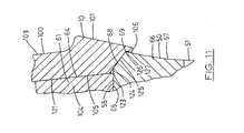
- FIG. 11 is a somewhat further enlarged fragmentary vertical section taken from a position indicated by line 11 - 11 in FIG. 8.
- the apparatus of the present invention is generally indicated by the numeral 10 in FIG. 2.
- the method and apparatus of the present invention are adapted for usage in a wide variety of environments and are particularly well suited to usage in surgical and other medical procedures such as where osseointegration is employed to reconstruct bone structure, tissue and the like in living organisms and, most particularly, human beings.
- osseointegration typically the restoration is accomplished through the use of pins, screws or other fastening devices which are implanted in predetermined locations and allowed to knit in those positions by the integration of the living bone matter and tissue with the implant.
- Such osseointegration requires typically several months to be achieved and must be accomplished for any subsequent surgical procedures can be performed.
- dental implant procedures such as, for example, of the type developed by Institut Straumann A. G. of Switzerland, Implant Innovations, Inc. and of other types such as shown and described in the prior art patents made of record in this case.
- the mouth of a patient is shown fragmentarily in FIG. 1 and generally indicated by the numeral 20 therein.
- the lower jaw of the mouth of the patient is generally indicated by the numeral 21 and may be viewed as having a proximal portion 22 and lateral extremities 23 .
- the lower jaw has an upper portion 24 .
- the lower jaw 21 has a lower jawbone, or mandible, 30 , with an upper surface 31 , as shown in FIG. 2.
- the lower jawbone is encased in gum tissue 32 which, for purposes of describing the method and apparatus of the present invention may be viewed as having an exterior surface 33 and an interior surface 34 contiguous with the lower jawbone.
- lower front teeth, or incisors are generally indicated by the numeral 40 and a lower back tooth, or molar, by the numeral 41 .
- a first work position, second work position and third work position are generally indicated by the numerals 42 , 43 and 44 , respectively.
- a work object or dental implant is generally indicated by the numeral 50 in the several views.
- the dental implant 50 shown in FIGS. 2, 3, 4 and 7 is the dental implant shown in the first work position 42 in FIG. 1.
- the dental implant 50 has a lower or base portion 51 which, in accordance with prevailing surgical procedures has been screw-thread ably inserted in the lower jawbone 30 in the first work position 42 .
- the base portion has a distal end portion 52 and an externally screw threaded portion 53 .
- the base portion has a proximal end portion 54 having a flat upper surface 55 which, at the time of the surgical implanting procedure, is disposed in coplanar relation to the upper surface 31 of the lower jawbone 30 .
- an externally screw threaded bore extends into the flat upper surface 55 of the base portion and extends axially of the base portion a predetermined distance.
- the dental implant 50 has an upper, or abutment portion, generally indicated by the numeral 61 and having a distal end portion 62 .
- the abutment portion has a tapered upper portion 63 having a substantially conical outer surface 64 .
- the abutment portion has a flat lower surface 65 .
- the abutment portion 61 and base portion 51 can be separated from each other, as will hereinafter be described, along a plane defined by the upper surface 55 of the base portion and lower surface 65 of the abutment portion.
- the proximal end portion 54 has an annular collar or shoulder 66 extending thereabout.
- the annular shoulder may be viewed as having a lower divergent surface 67 and an upper convergent surface 68 .
- the lower divergent surface and upper convergent surface are separated by an annulus or annular ridge 69 which extends about the annular shoulder defining a plane right-annularly related to the longitudinal axis of the dental implant and concentric thereto.
- a groove 80 is formed in the outer surface 64 of the tapered upper portion 63 of the abutment portion 61 extending therealong to a terminal surface 81 defining a plane right-angularly related to the longitudinal axis of the dental implant 50 .
- FIGS. 8 and 9 The apparatus 10 employed in the practice of the method of the present invention is shown herein in two embodiments shown respectively in FIGS. 8 and 9. For illustrative convenience, the two embodiments of the invention are described herein together.
- the apparatus 10 of the two embodiments has a body portion or housing 100 which can be fabricated of any suitable material.
- the housing is constructed of a thermal injected plastic material such as Bayer 348 ABS medical grade plastic which is molded in the configuration hereinafter described.
- the housing as shown in the drawings hereof, is larger than actual size for purposes of more clearly disclosing the structure thereof.
- the housing 100 may be viewed as having a distal portion 101 and an opposite proximal portion 102 .
- the housing has an outer surface 103 and encloses an interior chamber 104 defined by an interior surface 105 .
- the interior surface 105 is configured so as preferably to conform to the outer surface 64 of the abutment portion 61 of the dental implant 50 in fitted relation.
- the housing has a lower annulus 106 and an upper end wall 107 .
- the interior surface 105 of the housing 100 has a terminal surface 120 .
- a convergent surface 121 extends upwardly to communicate with the terminal surface 120 .
- a ridge portion 122 is formed in the convergent surface 121 and dimensioned and so configured as to mate with the groove 80 of the abutment portion 61 of the dental implant 50 .
- the interior surface 105 has an interior annulus 123 at the lower end of the convergent surface 121 and outwardly from which is extended in interior shoulder surface 124 .
- a sloped interior annular surface 125 extends downwardly and outwardly therefrom to an interior annulus 126 .
- the interior annulus 126 has an interior annular surface 127 shown best in FIG. 11.
- the interior annular surface is sloped in downwardly converging relation so as to permit the lower annulus 106 to be snap fitted on the annular ridge 69 of the annular shoulder 66 of the base portion 51 of the dental implant 50 .
- the housing 100 has an annular shoulder 140 which is of thickened proportions so as to occupy a predetermined amount of space, as can best be visualized in FIGS. 8 and 9.
- the annular shoulder has a sloped annular surface 141 and a beveled upper surface 142 .
- the configuration and dimensions of the annular shoulder 140 are, in the preferred embodiments, such as to occupy sufficient space to prevent the gum tissue 32 from incursion into the area bounding the annular shoulder 66 of the base portion 51 of the dental implant 50 , as will hereinafter be described in greater detail.
- a wide variety of other embodiments can be employed in the method and apparatus of the present invention.
- the housing 100 has a grasping portion 143 mounted on and integral with the upper end wall 107 of the housing 100 .
- the grasping portion has multiple prongs 144 , in this example three prongs, extending outwardly from the longitudinal axis of the housing 100 , as best shown in FIG. 8.
- the method of the present invention employs an implant analog generally indicated by the numeral 160 in FIGS. 5, 6 and 10 .
- the implant analog has a base portion 161 extending to a distal end portion 162 and having four rib portions 163 disposed at 90 degrees relative to each other.
- Each of the rib portions has a pair of arcuate recesses 164 .
- An annular collar or shoulder 166 extends upwardly from the rib portions 163 and includes a lower divergent surface 167 and an upper convergent surface 168 separated from each other by an annulus or ridge 169 . It will be seen that the annular shoulder 166 is so dimensioned and configured as to be identical to the annular shoulder 66 of the dental implant 50 .
- the implant analog 160 has an abutment portion 180 extending to a terminal surface 181 and having a groove 182 so configured and dimensioned as to conform to the ridge portion 122 of the convergent surface 121 of the interior surface 105 of the apparatus 10 and thus to the groove 80 of the dental implant 50 .
- FIG. 3 an impression tray 200 is fragmentarily shown therein defining an interior 201 containing mold material 202 .
- the outer surface of the mold material or, in other words, the impression made thereby is indicated at 203 and, if desired, an adhesive layer coating the apparatus 10 of the present invention can be employed which is generally indicated by the numeral 204 .
- a temporary dental appliance or crown is generally indicated by the numeral 210 into which a passage or interior 211 extends dimensioned to fit the outer surface 103 of the housing 100 of the apparatus 10 .
- an adhesive layer is generally indicated by the numeral 212 .
- dental stone is generally indicated by the numeral 220 .
- the surface of the dental stone providing the impression model is indicated by numeral 221 .
- a permanent dental appliance or crown is generally indicated by the numeral 230 .
- a passage or interior 231 extends into the permanent crown and is dimensioned to conform to the outer surface 64 of the abutment portion 61 of the dental implant 50 .
- An adhesive layer 232 attaches the permanent crown on the outer surface 64 .
- the outer surface of the permanent crown is indicated by the numeral 233 .
- the surface of the gum tissue 32 about the permanent crown is indicated by the numeral 234 .
- one or more dental implants 50 are installed in the upper and/or lower jawbone of the patient using otherwise conventional surgical or medical techniques.
- the dental implant 50 occupying first work position 42 will be assumed to be the site described. It will be understood, however, that the method of the present invention can be employed on one or more other work positions by varying the procedures accordingly.
- the dental implant 50 occupying the first work position 42 is permitted to osseointegrate with the lower jawbone 30 for a period of several months.
- the dental implant is ready to receive occlusal load and be restored by conventional dental means.
- the cover screw, not shown, which covers the entrance into the dental implant 50 is removed and the internal aspect is irrigated with an antimicrobial solution.
- the soft gum tissues and their integrity and position in relation to the collar of the dental implant are evaluated along with the interocclusal space between the dental implant or collar or shoulder and the opposing dentition.
- An appropriate height for the abutment portion 61 of the dental implant 50 is selected such as, for example, 4.0 millimeters, 5.5 millimeters, or 7.0 millimeters.
- the selected abutment portion is inserted into the internal aspect of the dental implant base portion 51 and screwed in a clockwise direction into place using an appropriate carrier device, not shown.
- the abutment portion 61 is tightened to 35 Ncm of pressure using a torque wrench moved in a clockwise direction.
- the abutment portion 61 and the annular collar or shoulder 66 of the base portion 51 are then isolated and dried.
- the apparatus 10 of the present invention is then positioned in covering relation to the abutment portion 61 and pressed downwardly until the lower annulus 106 snaps into place in fitted engagement with the annular ridge 69 of the annular collar 66 of the base portion 51 , as shown in FIGS. 2 and 11.
- the apparatus 10 is coated with a suitable adhesive and is roughened on the surface thereof to produce undercuts and grooves permitting retention in dental impression material.
- the prongs 144 also operate to retain the apparatus 10 in the dental impression material. Either or both of the undercuts and grooves on the one hand and/or the prongs on the other can be employed for this purpose.
- the impression tray 200 containing dental impression material 202 in the interior 201 thereof is positioned in the patient's mouth 20 to make a mold of the apparatus 10 , the adjacent teeth, the adjacent soft tissues and the opposing dentition. After an appropriate period of setting and hardening time, the impression tray is removed from the patient's mouth containing a mold of the teeth and removing the apparatus 10 from the dental implant 50 as shown in FIG. 3.
- a second apparatus 10 preferably of the form shown in FIG. 9, is trimmed to match the height of the abutment portion 61 and is snap fitted into the position shown in FIG. 4 again engaging the annular ridge 69 of the base portion 51 .
- the second apparatus 10 is used as a base for construction of the dental temporary restoration lined with dental acrylic and/or a temporary cement material.
- the temporary dental appliance or crown 210 is then mounted on the second apparatus 10 , as shown in FIG. 4. It will be seen that the annular shoulder 140 of the apparatus 10 operates to occlude the area bounding the annular shoulder 66 of base portion 51 so as to prevent the gum tissue 32 from growing into or otherwise occupying the area.
- the impression mold 203 is sent to a dental laboratory for fabrication of the dental restoration which will be mounted on the dental implant 50 .
- the implant analog 160 is inserted into the interior chamber 104 of the housing 100 of the apparatus 10 , as shown in FIG. 5. Sufficient pressure is exerted to cause the implant analog to snap into place with the lower annulus 106 of the housing 100 snapping over the annular ridge 169 of the annular shoulder 166 of the implant analog 160 .
- dental laboratory gypsum stone is mixed and poured into the impression 203 to reproduce a mold of the patient's mouth and implant suprastructure. After a period of setting time, the dental stone hardens and the impression tray is separated therefrom retaining the apparatus 10 of the present invention in the mold material 202 and leaving the implant analog 160 in the resulting dental stone 220 as best shown in FIG. 6.
- a third apparatus 10 of the present invention is trimmed to match the height of the implant analog in the dental stone 220 and inserted onto the abutment portion 180 of the implant analog until it snaps into place as previously described.
- This third apparatus 10 of the present invention is used as a waxing base for the construction of the dental restoration. Wax is applied directly onto the third apparatus 10 and carved to simulate the final tooth morphology, sprued, invested in dental bum-out investment and cast with metal alloys using the wax bum-out casting technique.
- the final restoration is polished, coated with porcelain or other suitable material and prepared for final installation in the patient's mouth.
- the resulting permanent crown 230 is ready for installation.
- the second apparatus 10 and temporary crown 210 are removed from the dental implant 50 from the position shown in FIG. 4.
- the area is irrigated with an antimicrobial solution.
- the soft tissues and their integrity and position in relation to the collar of the implant are also evaluated.
- the final restoration is seated on the abutment portion 61 of the dental implant 50 and the interproximal contact areas and occlusal contacts are adjusted to the desired fit.
- the adjusted permanent crown 230 is removed, the dental implant 50 is isolated and dried.
- the permanent crown 230 is filled with dental cement and then seated directly on the abutment portion 61 of the dental implant 50 .
- the cement is permitted to set for several minutes, excess cement is removed from the annular shoulder 66 of the base portion 51 and the area is irrigated once again with antimicrobial solution. Subsequently a dental radiograph is taken to confirm seating of the restoration and removal of the excess cement.
- the method and apparatus for isolating a work object of the present invention having particular utility in the practice of surgical procedures employing the technique of osseointegration; operate to ensure that the negative consequences experienced with the use of such surgical techniques are minimized; have particular utility in the surgical techniques employed in the use of osseointegration in the establishment of dental implants; operate to secure the surgical area over the lengthy period required for osseointegration to take place; are fully capable with surgical techniques presently employed in osseointegration in all surgical procedures, whether dental or for other specific purposes; and are otherwise fully capable of achieving their operational objectives.
Abstract
Description
- Not Applicable.
- Not Applicable.
- 1. Field of the Invention
- The present invention relates to a method and apparatus for isolating a work object and, more particularly, to such a method and apparatus which are operable with particular utility in surgical and other medical techniques and particularly those involving osseointegration.
- 2. Description of the Prior Art
- A variety of surgical procedures have long been employed to restore, or reinforce, the physiological integrity of living creatures, and particularly of human beings. While the earliest such surgical techniques focused on the restoration of, for example, the human skeletal structure, the same basic techniques have application to a wide variety of surgical and other medical applications with significant beneficial effect.
- It is known, for example, to use the technique of osseointegration to unite bone fragments for the purpose of restoring an arm, leg or other skeletal structure. This technique has been employed with beneficial effect in a wide variety of applications including, more recently, in the establishment of dental implants. For example, the Lazzara, et al. U.S. Pat. Nos. 4,846,683 and 4,850,870 disclose, respectively, prosthodontic restoration techniques which employ osseointegration to achieve attachment of the individual dental implants. These patents are merely representative of a wide variety of techniques, both patented and otherwise in usage, which permit the implacement of dental appliances at locations and with a permanency not heretofore achieved using prior art surgical techniques.
- It is apparent, however, that the use of such surgical techniques, whether for dental surgery or other surgical or medical purposes, presents difficulties which may not only interfere with the long term success of the technique, but may also cause unwarranted pain and other discomfort for the patient during the recovery period. More specifically, in the case of dental implant surgery, a condition develops because of the passage of time required for the osseointegration to be achieved. It is inherent in this surgical technique that a period of several months is required for the implant to join with the bone structure by the very process of osseointegration. It is also necessary to provide sufficient time for the dental restoration to be prepared by a dental laboratory. During this period of time, other physiological development occurs which may interfere, or complicate, the subsequent surgical procedures. The discomfort and pain of the patient experienced during these surgical procedures is well known and the long term success of the surgical procedure may be compromised. More specifically, the gum tissue proximate to the location in which the dental implant is undergoing osseointegration, and thereafter before the permanent dental appliance is installed, continues to grow and occludes the site of the implant. The natural tendency is for such gum tissues invade and to overlay the site of the implant during this period of time. After osseointegration has taken place, a solid abutment is attached to the implant. The dental appliance is subsequently attached to the abutment. It is required that the incursion of gum tissue be displaced from the location of the implant to permit the solid abutment and subsequently the dental appliance to be permanently affixed to the location. Typically, the removal of such gum tissue requires that the gum tissue be incised and extracted from the site to expose the implant and the area required for the abutment and dental appliance to be installed. This surgical procedure, of course, causes discomfort and pain to the patient as well as presenting the opportunity for infection and other medical complications which may significantly interfere with the overall success of the surgical procedure.
- Therefore, it has long been known that it would be desirable to have a method and apparatus for isolating a work object which have particular utility in the practice of surgical and other medical procedures employing the technique of osseointegration; which operate to ensure that the negative consequences experienced with the use of such surgical techniques are minimized; which have particular utility in the surgical techniques employed in the use of osseointegration in the establishment of dental implants; which operate to secure the surgical area over the lengthy period required for osseointegration to take place and subsequent surgical procedures to be performed; which are fully compatible with surgical techniques presently employed in osseointegration, whether dental or for other specific purposes; and which are otherwise fully capable of achieving their respective operational objectives.
- Therefore, it is an object of the present invention to provide an improved method and apparatus for isolating a work object.
- Another object is to provide such a method and apparatus which are adapted to usage in surgical and other medical techniques wherein the surgical area must conventionally be restored to a predefined condition in order for subsequent surgical, or other medical procedures, to be preformed.
- Another object is to provide such a method and apparatus which are particularly well suited to usage in all surgical techniques in which osseointegration is employed thereby requiring the passage of time to achieve integration between the medical appliance and the bone structure.
- Another object is to provide such a method and apparatus which are uniquely well suited to usage in such surgical techniques where the passage of time results in the incursion of tissue into the surgical area conventionally requiring removal, or displacement, in order to permit subsequent surgical procedures to be performed.
- Another object is to provide such a method and apparatus which possess the ability to preserve a surgical area over a lengthy period of time for the subsequent performance of restorative techniques, surgical techniques, or other medical procedures, in the surgical area while reducing to an absolute minimum the susceptibility of the surgical area to infection, or other medical incapacity.
- Another object is to provide such a method and apparatus which significantly enhance both the comfort of the patient and the likelihood of complete success in the performance of surgical producers.
- Another object is to provide such a method and apparatus which are fully compatible with conventional surgical and medical procedures and devices.
- Another object is to provide such a method and apparatus which require little specialized training so as to permit their adoption expeditiously and at minimal cost.
- Further objects and advantages are to provide improved elements and arrangements thereof in an apparatus for the purpose described which is dependable, economical, durable and fully effective in accomplishing its intended purposes.
- These and other objects and advantages are achieved, in the preferred embodiment of the present invention, in a method for isolating a work object to achieve a predetermined operational objective, the method including the steps of: encapsulating at least a portion of the work object in a housing in a work position so as to establish a zone of isolation relative to the portion of the work object; and occluding an area proximate to the housing to resist incursion into the area during a predetermined period of time.
- FIG. 1 is a fragmentary side elevation of the lower jaw, or mandible, of a patient representing a typical operative environment within which the method and apparatus of the present invention can be employed.
- FIG. 2 is a somewhat enlarged fragmentary vertical section of a work position depicted in FIG. 1 with the apparatus of the present invention installed in accordance with the method of the present invention and shown in larger than actual size.
- FIG. 3 is a somewhat reduced fragmentary vertical section showing the work position of FIG. 2 and depicting a subsequent step in the practice of the method of the present invention, producing a dental impression using an impression tray.
- FIG. 4 is a fragmentary vertical section of the work position shown in FIGS. 2 and 3 and showing the apparatus of the present invention and a temporary dental appliance employed in accordance with a subsequent step in the practice of the method of the present invention.
- FIG. 5 is a somewhat enlarged fragmentary vertical section of the impression tray shown in FIG. 3 and employed in a subsequent step in the practice of the method of the present invention employing, additionally, an implant analog.
- FIG. 6 is a fragmentary vertical section of the implant analog depicted in FIG. 5 and employed in an inverted attitude for purposes of the practice of a subsequent step in the method of the present invention.
- FIG. 7 is a somewhat enlarged fragmentary vertical section of the work position depicted in FIGS. 2, 3 and 4 showing a permanent crown mounted on the dental implant in accordance with a subsequent step in the practice of the method of the present invention.
- FIG. 8 is a somewhat enlarged, fragmentary perspective view of the embodiment of the apparatus of the present invention depicted in FIGS. 2 and 3.
- FIG. 9 is a side elevation of a second embodiment of the apparatus of the present invention depicted in FIG. 4.
- FIG. 10 is a somewhat enlarged side elevation of the implant analog depicted in FIGS. 5 and 6.
- FIG. 11 is a somewhat further enlarged fragmentary vertical section taken from a position indicated by line 11-11 in FIG. 8.
- Referring more particularly to the drawings, the apparatus of the present invention is generally indicated by the
numeral 10 in FIG. 2. - The method and apparatus of the present invention are adapted for usage in a wide variety of environments and are particularly well suited to usage in surgical and other medical procedures such as where osseointegration is employed to reconstruct bone structure, tissue and the like in living organisms and, most particularly, human beings. In such surgical environments of usage, typically the restoration is accomplished through the use of pins, screws or other fastening devices which are implanted in predetermined locations and allowed to knit in those positions by the integration of the living bone matter and tissue with the implant. Such osseointegration requires typically several months to be achieved and must be accomplished for any subsequent surgical procedures can be performed.
- In the illustrative environment hereof the method and apparatus of the present invention are employed with dental implant procedures such as, for example, of the type developed by Institut Straumann A. G. of Switzerland, Implant Innovations, Inc. and of other types such as shown and described in the prior art patents made of record in this case.
- In the illustrative environment shown herein, the mouth of a patient is shown fragmentarily in FIG. 1 and generally indicated by the
numeral 20 therein. As shown therein, the lower jaw of the mouth of the patient is generally indicated by thenumeral 21 and may be viewed as having aproximal portion 22 andlateral extremities 23. The lower jaw has anupper portion 24. - More specifically, the
lower jaw 21 has a lower jawbone, or mandible, 30, with anupper surface 31, as shown in FIG. 2. The lower jawbone is encased ingum tissue 32 which, for purposes of describing the method and apparatus of the present invention may be viewed as having anexterior surface 33 and aninterior surface 34 contiguous with the lower jawbone. - For purposes of illustrative convenience, as shown in FIG. 1, lower front teeth, or incisors, are generally indicated by the numeral 40 and a lower back tooth, or molar, by the numeral 41. Between the lower front teeth and the lower back tooth, a first work position, second work position and third work position are generally indicated by the
numerals - A work object or dental implant is generally indicated by the numeral 50 in the several views. For purposes of illustrative convenience, it will be understood that the
dental implant 50 shown in FIGS. 2, 3, 4 and 7 is the dental implant shown in thefirst work position 42 in FIG. 1. Thedental implant 50 has a lower orbase portion 51 which, in accordance with prevailing surgical procedures has been screw-thread ably inserted in thelower jawbone 30 in thefirst work position 42. The base portion has adistal end portion 52 and an externally screw threadedportion 53. The base portion has aproximal end portion 54 having a flatupper surface 55 which, at the time of the surgical implanting procedure, is disposed in coplanar relation to theupper surface 31 of thelower jawbone 30. It will be understood that an externally screw threaded bore extends into the flatupper surface 55 of the base portion and extends axially of the base portion a predetermined distance. - The
dental implant 50 has an upper, or abutment portion, generally indicated by the numeral 61 and having adistal end portion 62. The abutment portion has a taperedupper portion 63 having a substantially conicalouter surface 64. The abutment portion has a flatlower surface 65. As can be visualized in FIG. 2, theabutment portion 61 andbase portion 51 can be separated from each other, as will hereinafter be described, along a plane defined by theupper surface 55 of the base portion andlower surface 65 of the abutment portion. - Returning again to the structure of the
base portion 51 of thedental implant 50, theproximal end portion 54 has an annular collar orshoulder 66 extending thereabout. The annular shoulder may be viewed as having a lowerdivergent surface 67 and an upperconvergent surface 68. The lower divergent surface and upper convergent surface are separated by an annulus orannular ridge 69 which extends about the annular shoulder defining a plane right-annularly related to the longitudinal axis of the dental implant and concentric thereto. - A
groove 80 is formed in theouter surface 64 of the taperedupper portion 63 of theabutment portion 61 extending therealong to aterminal surface 81 defining a plane right-angularly related to the longitudinal axis of thedental implant 50. - The
apparatus 10 employed in the practice of the method of the present invention is shown herein in two embodiments shown respectively in FIGS. 8 and 9. For illustrative convenience, the two embodiments of the invention are described herein together. - The
apparatus 10 of the two embodiments has a body portion orhousing 100 which can be fabricated of any suitable material. In the preferred embodiment, the housing is constructed of a thermal injected plastic material such as Bayer 348ABS medical grade plastic which is molded in the configuration hereinafter described. In this regard it will be understood that the housing, as shown in the drawings hereof, is larger than actual size for purposes of more clearly disclosing the structure thereof. - The
housing 100 may be viewed as having adistal portion 101 and an oppositeproximal portion 102. The housing has anouter surface 103 and encloses aninterior chamber 104 defined by aninterior surface 105. As best shown in FIG. 4, theinterior surface 105 is configured so as preferably to conform to theouter surface 64 of theabutment portion 61 of thedental implant 50 in fitted relation. The housing has alower annulus 106 and anupper end wall 107. - The
interior surface 105 of thehousing 100 has aterminal surface 120. Aconvergent surface 121 extends upwardly to communicate with theterminal surface 120. As shown in FIG. 9, aridge portion 122 is formed in theconvergent surface 121 and dimensioned and so configured as to mate with thegroove 80 of theabutment portion 61 of thedental implant 50. Theinterior surface 105 has aninterior annulus 123 at the lower end of theconvergent surface 121 and outwardly from which is extended ininterior shoulder surface 124. A sloped interiorannular surface 125 extends downwardly and outwardly therefrom to aninterior annulus 126. Theinterior annulus 126 has an interiorannular surface 127 shown best in FIG. 11. The interior annular surface is sloped in downwardly converging relation so as to permit thelower annulus 106 to be snap fitted on theannular ridge 69 of theannular shoulder 66 of thebase portion 51 of thedental implant 50. - The
housing 100 has anannular shoulder 140 which is of thickened proportions so as to occupy a predetermined amount of space, as can best be visualized in FIGS. 8 and 9. The annular shoulder has a slopedannular surface 141 and a beveledupper surface 142. As can be visualized in FIGS. 2, 3 and 4, the configuration and dimensions of theannular shoulder 140 are, in the preferred embodiments, such as to occupy sufficient space to prevent thegum tissue 32 from incursion into the area bounding theannular shoulder 66 of thebase portion 51 of thedental implant 50, as will hereinafter be described in greater detail. A wide variety of other embodiments can be employed in the method and apparatus of the present invention. - As previously noted, two embodiments of the
apparatus 10 of the present invention are depicted in the drawings, those being in FIGS. 8 and 9. In the embodiment shown in FIG. 8, thehousing 100 has a graspingportion 143 mounted on and integral with theupper end wall 107 of thehousing 100. The grasping portion hasmultiple prongs 144, in this example three prongs, extending outwardly from the longitudinal axis of thehousing 100, as best shown in FIG. 8. - The method of the present invention employs an implant analog generally indicated by the numeral 160 in FIGS. 5, 6 and 10. The implant analog has a
base portion 161 extending to adistal end portion 162 and having fourrib portions 163 disposed at 90 degrees relative to each other. Each of the rib portions has a pair ofarcuate recesses 164. An annular collar orshoulder 166 extends upwardly from therib portions 163 and includes a lowerdivergent surface 167 and an upperconvergent surface 168 separated from each other by an annulus orridge 169. It will be seen that theannular shoulder 166 is so dimensioned and configured as to be identical to theannular shoulder 66 of thedental implant 50. - The
implant analog 160 has anabutment portion 180 extending to aterminal surface 181 and having agroove 182 so configured and dimensioned as to conform to theridge portion 122 of theconvergent surface 121 of theinterior surface 105 of theapparatus 10 and thus to thegroove 80 of thedental implant 50. - For illustrative convenience in describing the method of the present invention and the use of the
apparatus 10 hereof, reference is had in several of the views of the drawings to other elements to illustrate the environment of usage of the method and apparatus of the present invention. Thus, in FIG. 3 animpression tray 200 is fragmentarily shown therein defining an interior 201 containingmold material 202. The outer surface of the mold material or, in other words, the impression made thereby is indicated at 203 and, if desired, an adhesive layer coating theapparatus 10 of the present invention can be employed which is generally indicated by the numeral 204. - Referring more particularly to FIG. 4, a temporary dental appliance or crown is generally indicated by the numeral 210 into which a passage or interior 211 extends dimensioned to fit the
outer surface 103 of thehousing 100 of theapparatus 10. As shown in FIG. 4, an adhesive layer is generally indicated by the numeral 212. - Referring more particularly to FIG. 5, dental stone is generally indicated by the numeral 220. The surface of the dental stone providing the impression model is indicated by
numeral 221. - Referring then finally to FIG. 7, a permanent dental appliance or crown is generally indicated by the numeral 230. A passage or interior 231 extends into the permanent crown and is dimensioned to conform to the
outer surface 64 of theabutment portion 61 of thedental implant 50. Anadhesive layer 232 attaches the permanent crown on theouter surface 64. As shown therein, the outer surface of the permanent crown is indicated by the numeral 233. The surface of thegum tissue 32 about the permanent crown is indicated by the numeral 234. - The operation of the described embodiments of the subject invention and the method hereof are believed to be clearly apparent and are briefly described hereinafter.
- In the method of the present invention, one or more
dental implants 50 are installed in the upper and/or lower jawbone of the patient using otherwise conventional surgical or medical techniques. For illustrative convenience, and as previously described, thedental implant 50 occupyingfirst work position 42, as shown in FIG. 1, will be assumed to be the site described. It will be understood, however, that the method of the present invention can be employed on one or more other work positions by varying the procedures accordingly. - Again, using conventional surgical procedures, the
dental implant 50 occupying thefirst work position 42 is permitted to osseointegrate with thelower jawbone 30 for a period of several months. When this condition has been achieved, the dental implant is ready to receive occlusal load and be restored by conventional dental means. The cover screw, not shown, which covers the entrance into thedental implant 50 is removed and the internal aspect is irrigated with an antimicrobial solution. The soft gum tissues and their integrity and position in relation to the collar of the dental implant are evaluated along with the interocclusal space between the dental implant or collar or shoulder and the opposing dentition. - An appropriate height for the
abutment portion 61 of thedental implant 50 is selected such as, for example, 4.0 millimeters, 5.5 millimeters, or 7.0 millimeters. The selected abutment portion is inserted into the internal aspect of the dentalimplant base portion 51 and screwed in a clockwise direction into place using an appropriate carrier device, not shown. Theabutment portion 61 is tightened to 35 Ncm of pressure using a torque wrench moved in a clockwise direction. Theabutment portion 61 and the annular collar orshoulder 66 of thebase portion 51 are then isolated and dried. - The
apparatus 10 of the present invention is then positioned in covering relation to theabutment portion 61 and pressed downwardly until thelower annulus 106 snaps into place in fitted engagement with theannular ridge 69 of theannular collar 66 of thebase portion 51, as shown in FIGS. 2 and 11. - Subsequently, the
apparatus 10 is coated with a suitable adhesive and is roughened on the surface thereof to produce undercuts and grooves permitting retention in dental impression material. Theprongs 144 also operate to retain theapparatus 10 in the dental impression material. Either or both of the undercuts and grooves on the one hand and/or the prongs on the other can be employed for this purpose. - Referring to FIG. 3, the
impression tray 200 containingdental impression material 202 in theinterior 201 thereof is positioned in the patient'smouth 20 to make a mold of theapparatus 10, the adjacent teeth, the adjacent soft tissues and the opposing dentition. After an appropriate period of setting and hardening time, the impression tray is removed from the patient's mouth containing a mold of the teeth and removing theapparatus 10 from thedental implant 50 as shown in FIG. 3. - Referring next to FIG. 4, a
second apparatus 10 preferably of the form shown in FIG. 9, is trimmed to match the height of theabutment portion 61 and is snap fitted into the position shown in FIG. 4 again engaging theannular ridge 69 of thebase portion 51. Thesecond apparatus 10 is used as a base for construction of the dental temporary restoration lined with dental acrylic and/or a temporary cement material. The temporary dental appliance orcrown 210 is then mounted on thesecond apparatus 10, as shown in FIG. 4. It will be seen that theannular shoulder 140 of theapparatus 10 operates to occlude the area bounding theannular shoulder 66 ofbase portion 51 so as to prevent thegum tissue 32 from growing into or otherwise occupying the area. - In the meantime, the
impression mold 203 is sent to a dental laboratory for fabrication of the dental restoration which will be mounted on thedental implant 50. During this procedure, theimplant analog 160 is inserted into theinterior chamber 104 of thehousing 100 of theapparatus 10, as shown in FIG. 5. Sufficient pressure is exerted to cause the implant analog to snap into place with thelower annulus 106 of thehousing 100 snapping over theannular ridge 169 of theannular shoulder 166 of theimplant analog 160. - Then, using conventional laboratory techniques, dental laboratory gypsum stone is mixed and poured into the
impression 203 to reproduce a mold of the patient's mouth and implant suprastructure. After a period of setting time, the dental stone hardens and the impression tray is separated therefrom retaining theapparatus 10 of the present invention in themold material 202 and leaving theimplant analog 160 in the resultingdental stone 220 as best shown in FIG. 6. - At this time, a
third apparatus 10 of the present invention is trimmed to match the height of the implant analog in thedental stone 220 and inserted onto theabutment portion 180 of the implant analog until it snaps into place as previously described. Thisthird apparatus 10 of the present invention is used as a waxing base for the construction of the dental restoration. Wax is applied directly onto thethird apparatus 10 and carved to simulate the final tooth morphology, sprued, invested in dental bum-out investment and cast with metal alloys using the wax bum-out casting technique. The final restoration is polished, coated with porcelain or other suitable material and prepared for final installation in the patient's mouth. - The resulting
permanent crown 230, as described in the illustrative example shown in FIG. 7, is ready for installation. Thesecond apparatus 10 andtemporary crown 210 are removed from thedental implant 50 from the position shown in FIG. 4. The area is irrigated with an antimicrobial solution. The soft tissues and their integrity and position in relation to the collar of the implant are also evaluated. The final restoration is seated on theabutment portion 61 of thedental implant 50 and the interproximal contact areas and occlusal contacts are adjusted to the desired fit. The adjustedpermanent crown 230 is removed, thedental implant 50 is isolated and dried. Thepermanent crown 230 is filled with dental cement and then seated directly on theabutment portion 61 of thedental implant 50. The cement is permitted to set for several minutes, excess cement is removed from theannular shoulder 66 of thebase portion 51 and the area is irrigated once again with antimicrobial solution. Subsequently a dental radiograph is taken to confirm seating of the restoration and removal of the excess cement. - Therefore, the method and apparatus for isolating a work object of the present invention having particular utility in the practice of surgical procedures employing the technique of osseointegration; operate to ensure that the negative consequences experienced with the use of such surgical techniques are minimized; have particular utility in the surgical techniques employed in the use of osseointegration in the establishment of dental implants; operate to secure the surgical area over the lengthy period required for osseointegration to take place; are fully capable with surgical techniques presently employed in osseointegration in all surgical procedures, whether dental or for other specific purposes; and are otherwise fully capable of achieving their operational objectives.
- Although the invention has been herein shown and described in what is conceived to be the most practical and preferred embodiments, it is recognized that departures may be made therefrom within the scope of the invention which is not to be limited to the illustrative details disclosed.
Claims (19)
Priority Applications (1)
| Application Number | Priority Date | Filing Date | Title |
|---|---|---|---|
| US10/401,866 US7922488B2 (en) | 1998-02-26 | 2003-03-31 | Method and apparatus for isolating a work object |
Applications Claiming Priority (2)
| Application Number | Priority Date | Filing Date | Title |
|---|---|---|---|
| US09/031,440 US6540514B1 (en) | 1998-02-26 | 1998-02-26 | Method for isolating a dental implant |
| US10/401,866 US7922488B2 (en) | 1998-02-26 | 2003-03-31 | Method and apparatus for isolating a work object |
Related Parent Applications (1)
| Application Number | Title | Priority Date | Filing Date |
|---|---|---|---|
| US09/031,440 Continuation US6540514B1 (en) | 1998-02-26 | 1998-02-26 | Method for isolating a dental implant |
Publications (2)
| Publication Number | Publication Date |
|---|---|
| US20030190586A1 true US20030190586A1 (en) | 2003-10-09 |
| US7922488B2 US7922488B2 (en) | 2011-04-12 |
Family
ID=21859472
Family Applications (2)
| Application Number | Title | Priority Date | Filing Date |
|---|---|---|---|
| US09/031,440 Expired - Lifetime US6540514B1 (en) | 1998-02-26 | 1998-02-26 | Method for isolating a dental implant |
| US10/401,866 Expired - Fee Related US7922488B2 (en) | 1998-02-26 | 2003-03-31 | Method and apparatus for isolating a work object |
Family Applications Before (1)
| Application Number | Title | Priority Date | Filing Date |
|---|---|---|---|
| US09/031,440 Expired - Lifetime US6540514B1 (en) | 1998-02-26 | 1998-02-26 | Method for isolating a dental implant |
Country Status (1)
| Country | Link |
|---|---|
| US (2) | US6540514B1 (en) |
Cited By (7)
| Publication number | Priority date | Publication date | Assignee | Title |
|---|---|---|---|---|
| US20040101806A1 (en) * | 2002-09-12 | 2004-05-27 | Ajay Kumar | Dental impression coping with retention |
| US20060286508A1 (en) * | 2005-06-17 | 2006-12-21 | Zimmer Dental, Inc. | Dental restorative system and components |
| US20070037122A1 (en) * | 2005-06-17 | 2007-02-15 | Zimmer Dental, Inc. | Dental restorative system and components |
| US20100086900A1 (en) * | 2008-05-06 | 2010-04-08 | Keystone Dental, Inc. | Coping-analogue kit |
| US8007279B2 (en) | 2005-06-17 | 2011-08-30 | Zimmer Dental, Inc. | Dental restorative system and components |
| US20110269105A1 (en) * | 2010-04-29 | 2011-11-03 | Nt-Trading Gmbh & Co. Kg | Abutment for an implant system |
| EP3324877B1 (en) | 2015-07-24 | 2022-12-07 | Nobel Biocare Services AG | Adapter for attaching a first dental component to a second dental component and dental assembly comprising the adapter |
Families Citing this family (45)
| Publication number | Priority date | Publication date | Assignee | Title |
|---|---|---|---|---|
| US6540514B1 (en) * | 1998-02-26 | 2003-04-01 | Theodore S. Falk | Method for isolating a dental implant |
| FR2814058B1 (en) * | 2000-09-19 | 2005-10-28 | Guy Gabriel Peltier | SET OF IMPLANTS AND CORRESPONDING IMPLANTS |
| US7059856B2 (en) * | 2001-08-31 | 2006-06-13 | Leonard Marotta | Stable dental analog |
| US7018207B2 (en) * | 2002-02-22 | 2006-03-28 | Implant Innovations, Inc. | Dental implant analog having retention groove for soft tissue modeling |
| US6644970B1 (en) * | 2002-04-23 | 2003-11-11 | Fu Yi Lin | Gum adjusting and shaping device |
| ES2274172T3 (en) * | 2003-02-05 | 2007-05-16 | Straumann Holding Ag | PROLONGATION PART FOR A DENTAL IMPLANT, TRANSFER HELP AND PROCEDURE TO ESTABLISH A BASE FOR A RETAINING ELEMENT. |
| DE102004018512A1 (en) * | 2004-04-14 | 2005-11-17 | Robert Laux | Implant part in a dental implant |
| US20070099152A1 (en) * | 2005-10-31 | 2007-05-03 | Albert Busch | Dental implant system |
| ES2507071T3 (en) * | 2005-11-30 | 2014-10-14 | 3Shape A/S | Print scan to make dental repairs |
| ES2328759B1 (en) * | 2006-01-25 | 2010-09-14 | Createch Medical, S.L. | INFORMATION TRANSFER SYSTEM FOR ELABORATION OF PROTESIS ON DENTAL, MAXILOFACIAL AND ARTICULAR IMPLANTS. |
| ES2317789B1 (en) * | 2007-10-02 | 2010-02-25 | Francisco J. GARCIA SABAN | DOUBLE FUNCTION SYSTEM FOR DENTAL IMPLANTS. |
| US20090298015A1 (en) * | 2008-05-28 | 2009-12-03 | Global Implant Solutions, Llc | Digital Abutment For Dental Implant System |
| US20100015571A1 (en) * | 2008-07-15 | 2010-01-21 | Global Implant Solutions, Llc | Flexible Abutment For Use With A Dental Implant |
| US8454363B2 (en) * | 2008-11-06 | 2013-06-04 | William B. Worthington | Dental implant system |
| US20100151423A1 (en) * | 2008-12-11 | 2010-06-17 | Ranck Roger S | Temporary restorations and related methods |
| US20100151420A1 (en) * | 2008-12-11 | 2010-06-17 | Ranck Roger S | Fixtures for dental implants |
| US20100209877A1 (en) | 2009-02-13 | 2010-08-19 | Stephen Hogan | Components for use with implants and related methods |
| US20100159417A1 (en) * | 2008-12-18 | 2010-06-24 | Dale Whipple | Dental impression cap with engagement feature |
| US8075313B2 (en) * | 2009-01-19 | 2011-12-13 | Aeton Medical Llc | Transfer copings and related methods for taking implant impressions |
| WO2011056195A1 (en) * | 2009-11-06 | 2011-05-12 | Cortex Dental Implants Industries Ltd. | Anchor and method |
| US20110229850A1 (en) * | 2010-03-18 | 2011-09-22 | Bretton Joseph N | Dental coping and assembly with aligning anti-rotation feature |
| ITTO20110020A1 (en) * | 2011-01-14 | 2012-07-15 | Anna Nadia Trevisan | DENTAL ABUTMENT AND SYSTEM FOR DENTAL IMPRESSIONS USING A SIDE DENTAL ABUTMENT. |
| CH704382A1 (en) * | 2011-01-25 | 2012-07-31 | Dentalpoint Ag | Dentures system. |
| WO2012115969A2 (en) | 2011-02-21 | 2012-08-30 | Aeton Medical Llc | Abutment and abutment systems for use with implants |
| EP3777760A1 (en) * | 2011-05-16 | 2021-02-17 | Biomet 3I, LLC | Temporary abutment with combination of scanning features and provisionalization features |
| US8827702B2 (en) * | 2011-09-12 | 2014-09-09 | Cortex Dental Implant Industries, Ltd. | Driver and method |
| US10568720B2 (en) | 2012-01-10 | 2020-02-25 | Estetic Implant Solutions, LLC | Dental implants with markers for determining three-dimensional positioning |
| US10507081B2 (en) | 2012-01-10 | 2019-12-17 | Esthetic Implant Solutions, Llc | Methods for taking an impression or scanning without requiring removal of a temporary healing abutment |
| US10595970B2 (en) | 2012-01-10 | 2020-03-24 | Esthetic Implant Solutions, Llc | Bonding of soft gingival tissues with anatomical and other dental prostheses |
| US8628327B1 (en) * | 2012-10-02 | 2014-01-14 | Mark H. Blaisdell | Casting jig for chair-side manufacture of customizable sculptable anatomical healing caps |
| US10709525B2 (en) | 2012-01-10 | 2020-07-14 | Esthetic Implant Solutions, Llc | Methods for taking an oral scan without requiring removal of a temporary healing abutment |
| US9895209B2 (en) | 2012-01-10 | 2018-02-20 | Mark H. Blaisdell | Casting jig including elongate handle for chair-side manufacture of customizable sculptable anatomical healing caps, and method for forming bis-acrylic crown |
| US10016260B2 (en) | 2012-01-10 | 2018-07-10 | Mark H. Blaisdell | Anatomical healing abutments, kits, and methods |
| US9572640B2 (en) | 2012-10-02 | 2017-02-21 | Mark H. Blaisdell | Casting jig for chair-side manufacture of customizable sculptable anatomical healing caps |
| US11253345B2 (en) | 2012-01-10 | 2022-02-22 | Esthetic Implant Solutions, Llc | Methods for integrating scans including 3D cone beam scan for positioning of implant and fabrication of dental prosthesis |
| GB201212125D0 (en) | 2012-07-09 | 2012-08-22 | Nobel Biocare Services Ag | Abutment system and dental methods |
| US9414898B2 (en) * | 2014-02-18 | 2016-08-16 | Analoyd Ltd. | Dental implants—replicas of customized abutment and implant analogs |
| US10136974B2 (en) * | 2014-06-13 | 2018-11-27 | Vp Innovato Holdings Ltd | Molds for custom dental implant abutments and impression posts |
| US11903791B2 (en) * | 2014-09-12 | 2024-02-20 | Italo Lozada | Dental prosthesis |
| EP3474772B1 (en) | 2016-06-24 | 2020-04-22 | VP Innovato Holdings Ltd. | Dental tools system and method |
| US10383708B2 (en) * | 2016-06-28 | 2019-08-20 | University Of Connecticut | Analogs for dental restorations |
| WO2018172270A1 (en) * | 2017-03-20 | 2018-09-27 | Straumann Holding Ag | Implant analog |
| GR20170100383A (en) | 2017-08-21 | 2019-04-22 | Vp Innovato Holdings Ltd | Dental abutment core and method for manufacturing a dental abutment |
| US11559379B2 (en) | 2018-04-12 | 2023-01-24 | Esthetic Implant Solutions, Llc | Dental implants with markers for determining three-dimensional positioning |
| US11529218B2 (en) * | 2020-07-24 | 2022-12-20 | David Ziff | System and method for cementing parts into a screw retained implant crown |
Citations (57)
| Publication number | Priority date | Publication date | Assignee | Title |
|---|---|---|---|---|
| US3541689A (en) * | 1969-03-13 | 1970-11-24 | Ormco Corp | Gingival retraction ring |
| US3827145A (en) * | 1971-09-30 | 1974-08-06 | Plessey Handel Investment Ag | Artificial tooth structure |
| US4103422A (en) * | 1975-03-07 | 1978-08-01 | Oratronics, Inc. | Threaded self-tapping endodontic stabilizer |
| US4244689A (en) * | 1978-06-27 | 1981-01-13 | Arthur Ashman | Endosseous plastic implant |
| US4293302A (en) * | 1980-03-26 | 1981-10-06 | Scientific Advances, Inc. | Tooth implants |
| US4465462A (en) * | 1983-04-27 | 1984-08-14 | Ticknor Verne E | Gingival retraction cord |
| US4522593A (en) * | 1983-07-07 | 1985-06-11 | Fischer Dan E | Knitted gingival retraction cord |
| US4531916A (en) * | 1983-07-08 | 1985-07-30 | W. L. Gore & Associates, Inc. | Dental implant with expanded PTFE gingival interface |
| US4547157A (en) * | 1983-04-20 | 1985-10-15 | Miter, Inc. | Submergible post-type dental implant system and method of using same |
| US4575340A (en) * | 1985-02-04 | 1986-03-11 | Lustig Leopold P | Precision dental restorative system |
| US4687443A (en) * | 1983-04-20 | 1987-08-18 | Boehringer Mannheim Corporation | Submergible post-type dental implant system and method of using same |
| US4738623A (en) * | 1986-08-15 | 1988-04-19 | Quintron, Inc. | Dental implant and method |
| US4758161A (en) * | 1987-01-28 | 1988-07-19 | Core-Vent Corporation | Coping insert for use with a dental implant |
| US4790753A (en) * | 1987-02-13 | 1988-12-13 | Fradera Alejandro P | Screw for dental implants |
| US4824372A (en) * | 1987-05-13 | 1989-04-25 | Nobelpharma Ab | Apparatus for the fixation of a single-tooth restoration |
| US4838790A (en) * | 1986-07-07 | 1989-06-13 | Werner Koller | Dental sleeve and its use |
| US4850873A (en) * | 1988-04-04 | 1989-07-25 | Implant Innovations, Inc. | Prosthodontic restoration components |
| US4854872A (en) * | 1987-09-24 | 1989-08-08 | Detsch Steven G | Prosthetic implant attachment system and method |
| US4906191A (en) * | 1987-06-25 | 1990-03-06 | Astra Meditec Ab | Dental bridge |
| US4986753A (en) * | 1988-04-15 | 1991-01-22 | Sellers Grady C | Direct assembly framework for an osseointegrated implant |
| US5006069A (en) * | 1988-11-02 | 1991-04-09 | Implant Innovations, Inc. | Periodontal restoration components |
| US5049075A (en) * | 1987-12-23 | 1991-09-17 | Marc Barrut | Dentures, as well as temporary dentures, and process for their fabrication |
| US5073111A (en) * | 1989-10-20 | 1991-12-17 | Fereidoun Daftary | Anatomical restoration dental implant system |
| US5078606A (en) * | 1987-04-22 | 1992-01-07 | Astra Meditec Aktiebolag | Method for affixing a dental prosthesis |
| US5104318A (en) * | 1990-09-20 | 1992-04-14 | 2848-4293 Quebec Inc. | Implant assembly for anchoring an artificial tooth |
| US5106300A (en) * | 1990-09-26 | 1992-04-21 | Voitik Anton J | Dental implant attachment structure and method |
| US5125841A (en) * | 1990-01-18 | 1992-06-30 | Nobelpharma Ab | Impression top |
| US5135395A (en) * | 1990-07-05 | 1992-08-04 | Marlin Gerald M | Implant collar and post system |
| US5154612A (en) * | 1990-01-18 | 1992-10-13 | Nobelpharma Ab | Cap |
| US5180303A (en) * | 1988-09-21 | 1993-01-19 | Regents Of The University Of California | Retrievable dental prothesis apparatus and method of fabrication |
| US5259759A (en) * | 1991-03-27 | 1993-11-09 | Nobelpharma Ab | Temporary cylinder |
| US5286195A (en) * | 1989-12-07 | 1994-02-15 | Zl Microdent-Attachment Gmbh | Screw element for threadedly connecting a multi-part dental prosthesis |
| US5297963A (en) * | 1993-05-17 | 1994-03-29 | Fereidoun Dafatry | Anatomical restoration dental implant system with interlockable elliptical healing cap assembly and matching abutment member |
| US5336090A (en) * | 1993-11-30 | 1994-08-09 | Wilson Jr Richard S | Transmucosal healing cap and lockwasher for dental implants |
| US5344457A (en) * | 1986-05-19 | 1994-09-06 | The University Of Toronto Innovations Foundation | Porous surfaced implant |
| US5499918A (en) * | 1994-08-22 | 1996-03-19 | Diro, Inc. | Apparatus for preserving interdental papilla and method for using |
| US5527182A (en) * | 1993-12-23 | 1996-06-18 | Adt Advanced Dental Technologies, Ltd. | Implant abutment systems, devices, and techniques |
| US5540588A (en) * | 1994-11-02 | 1996-07-30 | Earle; Jeffrey O. | Teflon-coated intraoral tissue retraction cord |
| US5564924A (en) * | 1995-02-21 | 1996-10-15 | Kwan; Norman H. | Hexagonal abutment implant system |
| US5662476A (en) * | 1992-06-29 | 1997-09-02 | Nobel Biocare Ab | Prosthetic implant restoration method |
| US5681167A (en) * | 1996-01-05 | 1997-10-28 | Lazarof; Sargon | Dental assembly and process for preparing a tooth prosthesis |
| US5725375A (en) * | 1995-05-25 | 1998-03-10 | Implant Innovations, Inc. | Anti-rotational connecting mechanism |
| US5749731A (en) * | 1994-08-22 | 1998-05-12 | Diro, Inc. | Apparatus for preserving interdental papilla and method for using |
| US5797741A (en) * | 1994-05-31 | 1998-08-25 | Bonpard; Bruno | Dental implant article and device for fitting it |
| US5816809A (en) * | 1995-09-20 | 1998-10-06 | Genetic Implant Systems, Inc. | Dental prosthesis support device and method of using same |
| US5829977A (en) * | 1995-05-25 | 1998-11-03 | Implant Innovations, Inc. | Two-piece dental abutment |
| US5873722A (en) * | 1996-02-02 | 1999-02-23 | Implant Innovations, Inc. | Emergence profile system having a combined healing abutment and impression coping |
| US5899697A (en) * | 1994-11-08 | 1999-05-04 | Implant Innovations, Inc. | Anatomic interchangeable healing abutment and impression coping |
| US5904483A (en) * | 1995-11-17 | 1999-05-18 | Wade; Curtis K. | Dental implant systems and methods |
| US5906489A (en) * | 1998-06-10 | 1999-05-25 | Biotech Medical Instruments Corp. | Temporary dental implant |
| US6129548A (en) * | 1993-04-08 | 2000-10-10 | Implant Innovations, Inc. | Two-piece healing abutment system |
| US6135773A (en) * | 1997-01-27 | 2000-10-24 | Implant Innovations, Inc. | Single tooth alignment system |
| US6142782A (en) * | 1996-01-05 | 2000-11-07 | Lazarof; Sargon | Implant assembly and process for preparing a prosthetic device |
| US6217331B1 (en) * | 1997-10-03 | 2001-04-17 | Implant Innovations, Inc. | Single-stage implant system |
| US6227856B1 (en) * | 1997-01-27 | 2001-05-08 | Implant Innovations, Inc. | Abutment and coping system for use with dental implants |
| US6325628B1 (en) * | 1997-12-10 | 2001-12-04 | Diro, Inc. | Temporary implant components, system and method |
| US6540514B1 (en) * | 1998-02-26 | 2003-04-01 | Theodore S. Falk | Method for isolating a dental implant |
Family Cites Families (13)
| Publication number | Priority date | Publication date | Assignee | Title |
|---|---|---|---|---|
| DE3110693A1 (en) | 1981-03-19 | 1982-09-30 | Joannis Bademis | Jaw implant composed of an implant body and an epimobile attachment which can be screwed thereon and serves as an artificial stump for fastening of a denture part |
| DE3273726D1 (en) | 1981-05-07 | 1986-11-20 | Kenneth Henry Marshall | Production of tubes for dental impressions |
| FR2508307A1 (en) | 1981-09-16 | 1982-12-31 | Lonca Philippe | NEW DENTAL IMPLANTS AND ANCILLARY EQUIPMENT FOR THEIR IMPLEMENTATION |
| EP0139052A1 (en) | 1983-10-19 | 1985-05-02 | Peter Gabriel Mozsary | Osseointerfaced implanted artificial tooth |
| SE459152B (en) | 1986-11-06 | 1989-06-12 | Dan Lundgren | INTRAALVOLATED IMPLANT |
| US4850870C1 (en) | 1987-10-23 | 2001-07-24 | Implant Innovations Inc | Prosthodontic restoration components |
| US4846683A (en) | 1988-06-23 | 1989-07-11 | Implant Innovations, Inc. | Axially short dental implant fixture |
| US5040983A (en) | 1989-01-23 | 1991-08-20 | Implant Innovations, Inc. | Temporary dental coping |
| US5035619A (en) | 1989-10-20 | 1991-07-30 | Fereidoun Daftary | Anatomical restoration dental implant system with improved healing cap and abutment |
| ES2051239B1 (en) | 1992-11-24 | 1994-12-01 | Felechosa Alberto Sicilia | PROVISIONAL ABUTMENT FOR DENTAL PROTECTION IMPLANT. |
| US5492471A (en) | 1994-03-23 | 1996-02-20 | Gary Singer | Healing cap system |
| AU708386B2 (en) | 1996-02-08 | 1999-08-05 | Straumann Holding Ag | Impression system for an implant end protruding from the human tissue structure |
| US5860806A (en) * | 1996-11-29 | 1999-01-19 | The Kerr Corporation | Single dose dental adhesive delivery system and method and adhesive therefor |
-
1998
- 1998-02-26 US US09/031,440 patent/US6540514B1/en not_active Expired - Lifetime
-
2003
- 2003-03-31 US US10/401,866 patent/US7922488B2/en not_active Expired - Fee Related
Patent Citations (63)
| Publication number | Priority date | Publication date | Assignee | Title |
|---|---|---|---|---|
| US3541689A (en) * | 1969-03-13 | 1970-11-24 | Ormco Corp | Gingival retraction ring |
| US3827145A (en) * | 1971-09-30 | 1974-08-06 | Plessey Handel Investment Ag | Artificial tooth structure |
| US4103422A (en) * | 1975-03-07 | 1978-08-01 | Oratronics, Inc. | Threaded self-tapping endodontic stabilizer |
| US4244689A (en) * | 1978-06-27 | 1981-01-13 | Arthur Ashman | Endosseous plastic implant |
| US4293302A (en) * | 1980-03-26 | 1981-10-06 | Scientific Advances, Inc. | Tooth implants |
| US4547157A (en) * | 1983-04-20 | 1985-10-15 | Miter, Inc. | Submergible post-type dental implant system and method of using same |
| US4687443A (en) * | 1983-04-20 | 1987-08-18 | Boehringer Mannheim Corporation | Submergible post-type dental implant system and method of using same |
| US4465462A (en) * | 1983-04-27 | 1984-08-14 | Ticknor Verne E | Gingival retraction cord |
| US4522593A (en) * | 1983-07-07 | 1985-06-11 | Fischer Dan E | Knitted gingival retraction cord |
| US4531916A (en) * | 1983-07-08 | 1985-07-30 | W. L. Gore & Associates, Inc. | Dental implant with expanded PTFE gingival interface |
| US4575340A (en) * | 1985-02-04 | 1986-03-11 | Lustig Leopold P | Precision dental restorative system |
| US5344457A (en) * | 1986-05-19 | 1994-09-06 | The University Of Toronto Innovations Foundation | Porous surfaced implant |
| US4838790A (en) * | 1986-07-07 | 1989-06-13 | Werner Koller | Dental sleeve and its use |
| US4738623A (en) * | 1986-08-15 | 1988-04-19 | Quintron, Inc. | Dental implant and method |
| US4758161A (en) * | 1987-01-28 | 1988-07-19 | Core-Vent Corporation | Coping insert for use with a dental implant |
| US4790753A (en) * | 1987-02-13 | 1988-12-13 | Fradera Alejandro P | Screw for dental implants |
| US5078606A (en) * | 1987-04-22 | 1992-01-07 | Astra Meditec Aktiebolag | Method for affixing a dental prosthesis |
| US4824372A (en) * | 1987-05-13 | 1989-04-25 | Nobelpharma Ab | Apparatus for the fixation of a single-tooth restoration |
| US4906191A (en) * | 1987-06-25 | 1990-03-06 | Astra Meditec Ab | Dental bridge |
| US4854872A (en) * | 1987-09-24 | 1989-08-08 | Detsch Steven G | Prosthetic implant attachment system and method |
| US4854872B1 (en) * | 1987-09-24 | 1995-06-27 | Steven G Detsch | Prosthetic implant attachment system and method |
| US5049075A (en) * | 1987-12-23 | 1991-09-17 | Marc Barrut | Dentures, as well as temporary dentures, and process for their fabrication |
| US4850873A (en) * | 1988-04-04 | 1989-07-25 | Implant Innovations, Inc. | Prosthodontic restoration components |
| US4986753A (en) * | 1988-04-15 | 1991-01-22 | Sellers Grady C | Direct assembly framework for an osseointegrated implant |
| US5180303A (en) * | 1988-09-21 | 1993-01-19 | Regents Of The University Of California | Retrievable dental prothesis apparatus and method of fabrication |
| US5006069A (en) * | 1988-11-02 | 1991-04-09 | Implant Innovations, Inc. | Periodontal restoration components |
| US5073111A (en) * | 1989-10-20 | 1991-12-17 | Fereidoun Daftary | Anatomical restoration dental implant system |
| US5286195A (en) * | 1989-12-07 | 1994-02-15 | Zl Microdent-Attachment Gmbh | Screw element for threadedly connecting a multi-part dental prosthesis |
| US5125841A (en) * | 1990-01-18 | 1992-06-30 | Nobelpharma Ab | Impression top |
| US5154612A (en) * | 1990-01-18 | 1992-10-13 | Nobelpharma Ab | Cap |
| US5135395A (en) * | 1990-07-05 | 1992-08-04 | Marlin Gerald M | Implant collar and post system |
| US5104318A (en) * | 1990-09-20 | 1992-04-14 | 2848-4293 Quebec Inc. | Implant assembly for anchoring an artificial tooth |
| US5106300A (en) * | 1990-09-26 | 1992-04-21 | Voitik Anton J | Dental implant attachment structure and method |
| US5259759A (en) * | 1991-03-27 | 1993-11-09 | Nobelpharma Ab | Temporary cylinder |
| US5662476A (en) * | 1992-06-29 | 1997-09-02 | Nobel Biocare Ab | Prosthetic implant restoration method |
| US5871358A (en) * | 1992-06-29 | 1999-02-16 | Nobel Biocare Ab | Prosthetic implant restoration method |
| US6565357B1 (en) * | 1993-04-08 | 2003-05-20 | Implant Innovations, Inc. | Two-piece healing abutment system |
| US6129548A (en) * | 1993-04-08 | 2000-10-10 | Implant Innovations, Inc. | Two-piece healing abutment system |
| US5297963A (en) * | 1993-05-17 | 1994-03-29 | Fereidoun Dafatry | Anatomical restoration dental implant system with interlockable elliptical healing cap assembly and matching abutment member |
| US5336090A (en) * | 1993-11-30 | 1994-08-09 | Wilson Jr Richard S | Transmucosal healing cap and lockwasher for dental implants |
| US5527182A (en) * | 1993-12-23 | 1996-06-18 | Adt Advanced Dental Technologies, Ltd. | Implant abutment systems, devices, and techniques |
| US5797741A (en) * | 1994-05-31 | 1998-08-25 | Bonpard; Bruno | Dental implant article and device for fitting it |
| US5499918A (en) * | 1994-08-22 | 1996-03-19 | Diro, Inc. | Apparatus for preserving interdental papilla and method for using |
| US5749731A (en) * | 1994-08-22 | 1998-05-12 | Diro, Inc. | Apparatus for preserving interdental papilla and method for using |
| US5540588A (en) * | 1994-11-02 | 1996-07-30 | Earle; Jeffrey O. | Teflon-coated intraoral tissue retraction cord |
| US6120293A (en) * | 1994-11-08 | 2000-09-19 | Implant Innovations, Inc. | Abutment for a temporary tooth |
| US5899697A (en) * | 1994-11-08 | 1999-05-04 | Implant Innovations, Inc. | Anatomic interchangeable healing abutment and impression coping |
| US5564924A (en) * | 1995-02-21 | 1996-10-15 | Kwan; Norman H. | Hexagonal abutment implant system |
| US5829977A (en) * | 1995-05-25 | 1998-11-03 | Implant Innovations, Inc. | Two-piece dental abutment |
| US5725375A (en) * | 1995-05-25 | 1998-03-10 | Implant Innovations, Inc. | Anti-rotational connecting mechanism |
| US5816809A (en) * | 1995-09-20 | 1998-10-06 | Genetic Implant Systems, Inc. | Dental prosthesis support device and method of using same |
| US5904483A (en) * | 1995-11-17 | 1999-05-18 | Wade; Curtis K. | Dental implant systems and methods |
| US5762500A (en) * | 1996-01-05 | 1998-06-09 | Lazarof; Sargon | Process for preparing a tooth prosthesis for attachment to an abutment within a mouth of a patient |
| US6142782A (en) * | 1996-01-05 | 2000-11-07 | Lazarof; Sargon | Implant assembly and process for preparing a prosthetic device |
| US5681167A (en) * | 1996-01-05 | 1997-10-28 | Lazarof; Sargon | Dental assembly and process for preparing a tooth prosthesis |
| US5873722A (en) * | 1996-02-02 | 1999-02-23 | Implant Innovations, Inc. | Emergence profile system having a combined healing abutment and impression coping |
| US6135773A (en) * | 1997-01-27 | 2000-10-24 | Implant Innovations, Inc. | Single tooth alignment system |
| US6227856B1 (en) * | 1997-01-27 | 2001-05-08 | Implant Innovations, Inc. | Abutment and coping system for use with dental implants |
| US6217331B1 (en) * | 1997-10-03 | 2001-04-17 | Implant Innovations, Inc. | Single-stage implant system |
| US6394809B2 (en) * | 1997-10-03 | 2002-05-28 | Implant Innovations, Inc. | Single-stage implant system |
| US6325628B1 (en) * | 1997-12-10 | 2001-12-04 | Diro, Inc. | Temporary implant components, system and method |
| US6540514B1 (en) * | 1998-02-26 | 2003-04-01 | Theodore S. Falk | Method for isolating a dental implant |
| US5906489A (en) * | 1998-06-10 | 1999-05-25 | Biotech Medical Instruments Corp. | Temporary dental implant |
Cited By (11)
| Publication number | Priority date | Publication date | Assignee | Title |
|---|---|---|---|---|
| US20040101806A1 (en) * | 2002-09-12 | 2004-05-27 | Ajay Kumar | Dental impression coping with retention |
| US7066736B2 (en) | 2002-09-12 | 2006-06-27 | Zimmer Dental, Inc. | Dental impression coping with retention |
| US20060286508A1 (en) * | 2005-06-17 | 2006-12-21 | Zimmer Dental, Inc. | Dental restorative system and components |
| US20070037122A1 (en) * | 2005-06-17 | 2007-02-15 | Zimmer Dental, Inc. | Dental restorative system and components |
| US8007279B2 (en) | 2005-06-17 | 2011-08-30 | Zimmer Dental, Inc. | Dental restorative system and components |
| US8430668B2 (en) | 2005-06-17 | 2013-04-30 | Zimmer Dental, Inc. | Dental restorative system and components |
| US8506296B2 (en) | 2005-06-17 | 2013-08-13 | Zimmer Dental, Inc. | Dental restorative system and components |
| US9125710B2 (en) | 2005-06-17 | 2015-09-08 | Zimmer Dental, Inc. | Dental restorative system and components |
| US20100086900A1 (en) * | 2008-05-06 | 2010-04-08 | Keystone Dental, Inc. | Coping-analogue kit |
| US20110269105A1 (en) * | 2010-04-29 | 2011-11-03 | Nt-Trading Gmbh & Co. Kg | Abutment for an implant system |
| EP3324877B1 (en) | 2015-07-24 | 2022-12-07 | Nobel Biocare Services AG | Adapter for attaching a first dental component to a second dental component and dental assembly comprising the adapter |
Also Published As
| Publication number | Publication date |
|---|---|
| US6540514B1 (en) | 2003-04-01 |
| US7922488B2 (en) | 2011-04-12 |
Similar Documents
| Publication | Publication Date | Title |
|---|---|---|
| US6540514B1 (en) | Method for isolating a dental implant | |
| AU2006227608B2 (en) | Transfer coping for dental implants | |
| EP1263345B1 (en) | Snap-in impression coping | |
| US4856994A (en) | Periodontal restoration components | |
| EP1317221B1 (en) | Impression cap | |
| US6394806B1 (en) | Snap-in healing cap | |
| US5674073A (en) | Impression coping | |
| US6644969B2 (en) | Snap-in healing cap and insertion tool | |
| US5336090A (en) | Transmucosal healing cap and lockwasher for dental implants | |
| US20070281278A1 (en) | Transfer coping for dental implants | |
| US4708654A (en) | Positive cast model of an upper and lower jaw, and a method and means for producing such a model | |
| US6325628B1 (en) | Temporary implant components, system and method | |
| US20060263747A1 (en) | Healing cap for dental implants | |
| US20060121416A1 (en) | Multiple use impression coping | |
| CA2643036A1 (en) | Ceramic/metallic dental abutment | |
| Balshi | The Biotes conversion prosthesis: a provisional fixed prosthesis supported by osseointegrated titanium fixtures for restoration of the edentulous jaw | |
| JPH0244540B2 (en) | ||
| US11103331B2 (en) | Convertible dental assembly | |
| JP2538836Y2 (en) | Dental implant material | |
| JP3713318B2 (en) | Artificial tooth root | |
| JPH0492658A (en) | Removable prosthesis and implant for removable prosthesis | |
| JPH0424056B2 (en) |
Legal Events
| Date | Code | Title | Description |
|---|---|---|---|
| AS | Assignment |
Owner name: INSTITUT STRAUMANN AG, SWITZERLAND Free format text: ASSIGNMENT OF ASSIGNORS INTEREST;ASSIGNOR:SIMPLIFIED IMPLANT SYSTEMS, LLC;REEL/FRAME:014585/0613 Effective date: 20030926 Owner name: INSTITUT STRAUMANN AG, SWITZERLAND Free format text: ASSIGNMENT OF ASSIGNORS INTEREST;ASSIGNOR:FALK, THEODORE S.;REEL/FRAME:014580/0656 Effective date: 20030926 Owner name: INSTITUT STRAUMANN AG, SWITZERLAND Free format text: ASSIGNMENT OF ASSIGNORS INTEREST;ASSIGNOR:BRAMANTI, THOMAS E.;REEL/FRAME:014580/0651 Effective date: 20030926 |
|
| FEPP | Fee payment procedure |
Free format text: PAYOR NUMBER ASSIGNED (ORIGINAL EVENT CODE: ASPN); ENTITY STATUS OF PATENT OWNER: LARGE ENTITY |
|
| STCF | Information on status: patent grant |
Free format text: PATENTED CASE |
|
| FPAY | Fee payment |
Year of fee payment: 4 |
|
| FEPP | Fee payment procedure |
Free format text: MAINTENANCE FEE REMINDER MAILED (ORIGINAL EVENT CODE: REM.); ENTITY STATUS OF PATENT OWNER: LARGE ENTITY |
|
| LAPS | Lapse for failure to pay maintenance fees |
Free format text: PATENT EXPIRED FOR FAILURE TO PAY MAINTENANCE FEES (ORIGINAL EVENT CODE: EXP.); ENTITY STATUS OF PATENT OWNER: LARGE ENTITY |
|
| STCH | Information on status: patent discontinuation |
Free format text: PATENT EXPIRED DUE TO NONPAYMENT OF MAINTENANCE FEES UNDER 37 CFR 1.362 |
|
| FP | Lapsed due to failure to pay maintenance fee |
Effective date: 20190412 |