US20030190874A1 - Composite conditioning tool - Google Patents
Composite conditioning tool Download PDFInfo
- Publication number
- US20030190874A1 US20030190874A1 US10/405,542 US40554203A US2003190874A1 US 20030190874 A1 US20030190874 A1 US 20030190874A1 US 40554203 A US40554203 A US 40554203A US 2003190874 A1 US2003190874 A1 US 2003190874A1
- Authority
- US
- United States
- Prior art keywords
- polishing
- section
- polishing pad
- conditioning
- pad
- Prior art date
- Legal status (The legal status is an assumption and is not a legal conclusion. Google has not performed a legal analysis and makes no representation as to the accuracy of the status listed.)
- Abandoned
Links
- 230000003750 conditioning effect Effects 0.000 title claims abstract description 80
- 239000002131 composite material Substances 0.000 title description 12
- 238000005498 polishing Methods 0.000 claims abstract description 134
- 239000000463 material Substances 0.000 claims abstract description 31
- 238000005520 cutting process Methods 0.000 claims abstract description 9
- 238000000034 method Methods 0.000 claims description 27
- 230000001143 conditioned effect Effects 0.000 claims description 3
- 239000012530 fluid Substances 0.000 claims description 3
- 238000004140 cleaning Methods 0.000 description 32
- 239000002002 slurry Substances 0.000 description 20
- 230000008569 process Effects 0.000 description 19
- 238000005201 scrubbing Methods 0.000 description 19
- 239000006227 byproduct Substances 0.000 description 17
- 239000010432 diamond Substances 0.000 description 17
- 235000012431 wafers Nutrition 0.000 description 17
- 229910003460 diamond Inorganic materials 0.000 description 16
- XLYOFNOQVPJJNP-UHFFFAOYSA-N water Substances O XLYOFNOQVPJJNP-UHFFFAOYSA-N 0.000 description 9
- 239000004065 semiconductor Substances 0.000 description 8
- RYGMFSIKBFXOCR-UHFFFAOYSA-N Copper Chemical compound [Cu] RYGMFSIKBFXOCR-UHFFFAOYSA-N 0.000 description 7
- 229910052802 copper Inorganic materials 0.000 description 7
- 239000010949 copper Substances 0.000 description 7
- 239000000758 substrate Substances 0.000 description 7
- XUIMIQQOPSSXEZ-UHFFFAOYSA-N Silicon Chemical compound [Si] XUIMIQQOPSSXEZ-UHFFFAOYSA-N 0.000 description 6
- 238000011065 in-situ storage Methods 0.000 description 6
- 229920000642 polymer Polymers 0.000 description 6
- 239000010703 silicon Substances 0.000 description 6
- 229910052710 silicon Inorganic materials 0.000 description 6
- 238000011066 ex-situ storage Methods 0.000 description 5
- VYPSYNLAJGMNEJ-UHFFFAOYSA-N Silicium dioxide Chemical compound O=[Si]=O VYPSYNLAJGMNEJ-UHFFFAOYSA-N 0.000 description 4
- 238000006243 chemical reaction Methods 0.000 description 4
- 230000007423 decrease Effects 0.000 description 4
- 239000007788 liquid Substances 0.000 description 4
- 229910052751 metal Inorganic materials 0.000 description 4
- 239000002184 metal Substances 0.000 description 4
- 239000002245 particle Substances 0.000 description 3
- NIXOWILDQLNWCW-UHFFFAOYSA-M acrylate group Chemical group C(C=C)(=O)[O-] NIXOWILDQLNWCW-UHFFFAOYSA-M 0.000 description 2
- 150000001408 amides Chemical class 0.000 description 2
- 229920001577 copolymer Polymers 0.000 description 2
- 238000009826 distribution Methods 0.000 description 2
- 125000003700 epoxy group Chemical group 0.000 description 2
- 238000004519 manufacturing process Methods 0.000 description 2
- 238000012986 modification Methods 0.000 description 2
- 230000004048 modification Effects 0.000 description 2
- BASFCYQUMIYNBI-UHFFFAOYSA-N platinum Chemical compound [Pt] BASFCYQUMIYNBI-UHFFFAOYSA-N 0.000 description 2
- 229920000647 polyepoxide Polymers 0.000 description 2
- 239000000377 silicon dioxide Substances 0.000 description 2
- 150000003673 urethanes Chemical class 0.000 description 2
- 239000002699 waste material Substances 0.000 description 2
- HRPVXLWXLXDGHG-UHFFFAOYSA-N Acrylamide Chemical group NC(=O)C=C HRPVXLWXLXDGHG-UHFFFAOYSA-N 0.000 description 1
- BVKZGUZCCUSVTD-UHFFFAOYSA-L Carbonate Chemical compound [O-]C([O-])=O BVKZGUZCCUSVTD-UHFFFAOYSA-L 0.000 description 1
- VGGSQFUCUMXWEO-UHFFFAOYSA-N Ethene Chemical compound C=C VGGSQFUCUMXWEO-UHFFFAOYSA-N 0.000 description 1
- IMROMDMJAWUWLK-UHFFFAOYSA-N Ethenol Chemical compound OC=C IMROMDMJAWUWLK-UHFFFAOYSA-N 0.000 description 1
- JOYRKODLDBILNP-UHFFFAOYSA-N Ethyl urethane Chemical compound CCOC(N)=O JOYRKODLDBILNP-UHFFFAOYSA-N 0.000 description 1
- 239000005977 Ethylene Substances 0.000 description 1
- CERQOIWHTDAKMF-UHFFFAOYSA-M Methacrylate Chemical compound CC(=C)C([O-])=O CERQOIWHTDAKMF-UHFFFAOYSA-M 0.000 description 1
- 239000004952 Polyamide Substances 0.000 description 1
- 229920005830 Polyurethane Foam Polymers 0.000 description 1
- BOTDANWDWHJENH-UHFFFAOYSA-N Tetraethyl orthosilicate Chemical compound CCO[Si](OCC)(OCC)OCC BOTDANWDWHJENH-UHFFFAOYSA-N 0.000 description 1
- BZHJMEDXRYGGRV-UHFFFAOYSA-N Vinyl chloride Chemical compound ClC=C BZHJMEDXRYGGRV-UHFFFAOYSA-N 0.000 description 1
- QYKIQEUNHZKYBP-UHFFFAOYSA-N Vinyl ether Chemical class C=COC=C QYKIQEUNHZKYBP-UHFFFAOYSA-N 0.000 description 1
- 239000003082 abrasive agent Substances 0.000 description 1
- 238000009825 accumulation Methods 0.000 description 1
- 239000002253 acid Substances 0.000 description 1
- 239000000853 adhesive Substances 0.000 description 1
- 230000001070 adhesive effect Effects 0.000 description 1
- 238000013019 agitation Methods 0.000 description 1
- 229910052782 aluminium Inorganic materials 0.000 description 1
- XAGFODPZIPBFFR-UHFFFAOYSA-N aluminium Chemical compound [Al] XAGFODPZIPBFFR-UHFFFAOYSA-N 0.000 description 1
- 229920003180 amino resin Chemical class 0.000 description 1
- 230000009286 beneficial effect Effects 0.000 description 1
- 230000008901 benefit Effects 0.000 description 1
- 125000001797 benzyl group Chemical class [H]C1=C([H])C([H])=C(C([H])=C1[H])C([H])([H])* 0.000 description 1
- 125000002915 carbonyl group Chemical group [*:2]C([*:1])=O 0.000 description 1
- 125000003178 carboxy group Chemical class [H]OC(*)=O 0.000 description 1
- 229910052681 coesite Inorganic materials 0.000 description 1
- 150000001875 compounds Chemical class 0.000 description 1
- UCFCTSYWEPBANH-UHFFFAOYSA-N copper benzotriazol-1-ide Chemical compound [Cu+2].C1=CC=C2[N-]N=NC2=C1.C1=CC=C2[N-]N=NC2=C1 UCFCTSYWEPBANH-UHFFFAOYSA-N 0.000 description 1
- 229910052906 cristobalite Inorganic materials 0.000 description 1
- 238000005202 decontamination Methods 0.000 description 1
- 230000003588 decontaminative effect Effects 0.000 description 1
- 230000007547 defect Effects 0.000 description 1
- 230000008021 deposition Effects 0.000 description 1
- 239000003989 dielectric material Substances 0.000 description 1
- 239000012153 distilled water Substances 0.000 description 1
- 230000000694 effects Effects 0.000 description 1
- 230000003628 erosive effect Effects 0.000 description 1
- 150000002148 esters Chemical class 0.000 description 1
- 239000000835 fiber Substances 0.000 description 1
- 230000009477 glass transition Effects 0.000 description 1
- ZFSLODLOARCGLH-UHFFFAOYSA-N isocyanuric acid Chemical class OC1=NC(O)=NC(O)=N1 ZFSLODLOARCGLH-UHFFFAOYSA-N 0.000 description 1
- 239000011159 matrix material Substances 0.000 description 1
- 230000007246 mechanism Effects 0.000 description 1
- 239000000203 mixture Substances 0.000 description 1
- 150000004767 nitrides Chemical class 0.000 description 1
- 150000002894 organic compounds Chemical class 0.000 description 1
- 230000000737 periodic effect Effects 0.000 description 1
- 238000000206 photolithography Methods 0.000 description 1
- 229910052697 platinum Inorganic materials 0.000 description 1
- 229920003229 poly(methyl methacrylate) Polymers 0.000 description 1
- 229920002492 poly(sulfone) Polymers 0.000 description 1
- 229920002401 polyacrylamide Polymers 0.000 description 1
- 229920002647 polyamide Polymers 0.000 description 1
- 239000004417 polycarbonate Substances 0.000 description 1
- 229920000515 polycarbonate Polymers 0.000 description 1
- 229910021420 polycrystalline silicon Inorganic materials 0.000 description 1
- 239000004814 polyurethane Substances 0.000 description 1
- 229920002635 polyurethane Polymers 0.000 description 1
- 239000011496 polyurethane foam Substances 0.000 description 1
- 229920002451 polyvinyl alcohol Polymers 0.000 description 1
- 235000019422 polyvinyl alcohol Nutrition 0.000 description 1
- 239000004800 polyvinyl chloride Substances 0.000 description 1
- 229920000915 polyvinyl chloride Polymers 0.000 description 1
- 239000002244 precipitate Substances 0.000 description 1
- 238000003825 pressing Methods 0.000 description 1
- 230000002787 reinforcement Effects 0.000 description 1
- 239000007787 solid Substances 0.000 description 1
- 239000007921 spray Substances 0.000 description 1
- 229910052682 stishovite Inorganic materials 0.000 description 1
- 239000000126 substance Substances 0.000 description 1
- 150000003457 sulfones Chemical class 0.000 description 1
- 229920001169 thermoplastic Polymers 0.000 description 1
- 229920001187 thermosetting polymer Polymers 0.000 description 1
- 239000004416 thermosoftening plastic Substances 0.000 description 1
- 238000012876 topography Methods 0.000 description 1
- 229910052905 tridymite Inorganic materials 0.000 description 1
- WFKWXMTUELFFGS-UHFFFAOYSA-N tungsten Chemical compound [W] WFKWXMTUELFFGS-UHFFFAOYSA-N 0.000 description 1
- 229910052721 tungsten Inorganic materials 0.000 description 1
- 239000010937 tungsten Substances 0.000 description 1
Images


Classifications
-
- B—PERFORMING OPERATIONS; TRANSPORTING
- B24—GRINDING; POLISHING
- B24B—MACHINES, DEVICES, OR PROCESSES FOR GRINDING OR POLISHING; DRESSING OR CONDITIONING OF ABRADING SURFACES; FEEDING OF GRINDING, POLISHING, OR LAPPING AGENTS
- B24B37/00—Lapping machines or devices; Accessories
- B24B37/27—Work carriers
- B24B37/30—Work carriers for single side lapping of plane surfaces
-
- B—PERFORMING OPERATIONS; TRANSPORTING
- B24—GRINDING; POLISHING
- B24B—MACHINES, DEVICES, OR PROCESSES FOR GRINDING OR POLISHING; DRESSING OR CONDITIONING OF ABRADING SURFACES; FEEDING OF GRINDING, POLISHING, OR LAPPING AGENTS
- B24B29/00—Machines or devices for polishing surfaces on work by means of tools made of soft or flexible material with or without the application of solid or liquid polishing agents
- B24B29/005—Machines or devices for polishing surfaces on work by means of tools made of soft or flexible material with or without the application of solid or liquid polishing agents using brushes
-
- B—PERFORMING OPERATIONS; TRANSPORTING
- B24—GRINDING; POLISHING
- B24B—MACHINES, DEVICES, OR PROCESSES FOR GRINDING OR POLISHING; DRESSING OR CONDITIONING OF ABRADING SURFACES; FEEDING OF GRINDING, POLISHING, OR LAPPING AGENTS
- B24B53/00—Devices or means for dressing or conditioning abrasive surfaces
- B24B53/017—Devices or means for dressing, cleaning or otherwise conditioning lapping tools
-
- B—PERFORMING OPERATIONS; TRANSPORTING
- B24—GRINDING; POLISHING
- B24B—MACHINES, DEVICES, OR PROCESSES FOR GRINDING OR POLISHING; DRESSING OR CONDITIONING OF ABRADING SURFACES; FEEDING OF GRINDING, POLISHING, OR LAPPING AGENTS
- B24B53/00—Devices or means for dressing or conditioning abrasive surfaces
- B24B53/12—Dressing tools; Holders therefor
-
- B—PERFORMING OPERATIONS; TRANSPORTING
- B24—GRINDING; POLISHING
- B24B—MACHINES, DEVICES, OR PROCESSES FOR GRINDING OR POLISHING; DRESSING OR CONDITIONING OF ABRADING SURFACES; FEEDING OF GRINDING, POLISHING, OR LAPPING AGENTS
- B24B57/00—Devices for feeding, applying, grading or recovering grinding, polishing or lapping agents
- B24B57/02—Devices for feeding, applying, grading or recovering grinding, polishing or lapping agents for feeding of fluid, sprayed, pulverised, or liquefied grinding, polishing or lapping agents
Definitions
- the present invention relates, in general, to a system for cleaning and conditioning polish pads used to polish silicon wafers and semiconductors and, more particularly, to pad cleaning during polishing and pad conditioning and cleaning.
- Silicon wafers are commonly used as a base on which multi-level integrated circuits are fabricated.
- Integrated circuits on semiconductor wafers are manufactured with a layer of an insulating layer or semi-conductive or conductive metal substrate layer.
- This layer can be a dielectric, such as, silica including SiO 2 and TEOS. It can also be a low K dielectric, poly-silicon or metal such as tungsten, aluminum, copper and platinum.
- a series of deposition and etch steps are required to form a multi-level pattern on a semiconductor wafer.
- Silicon wafers for the semiconductor industry must possess a high degree of surface perfection before they can be useful in the device fabrication process.
- a non-planar silicon wafer surface during the manufacturing process causes a focusing problem for photolithography and results in lower yield and decreases performance of the semiconductor device.
- a polishing system known as CMP referred to as either or both, chemical-mechanical planarization and chemical-mechanical polishing of non-planar wafer is utilized in a conventional process.
- the CMP process is used to planarize the insulating layer on a silicon wafer.
- a CMP process can be used for an insulating layer whether it is a dielectric material, conductive metal or semi-conductive layer.
- the CMP process utilizes different polishing pads and polishing compositions or slurries. Further details of CMP polishing features and operation of a polishing apparatus for a CMP process may be found in U.S. Pat. No. 5,738,574.
- a CMP process the wafer is pressed against a moving polishing pad.
- the silicon wafer is bathed or rinsed in a polishing slurry in conjunction with an elastomeric pad that is pressed against the substrate and rotated such that the slurry particles are pressed against the substrate under load.
- the lateral motion of the pad causes the slurry particles to move across the substrate surface, resulting in wear, or volumetric removal of the substrate surface.
- this process results in the selective erosion of projecting surface features so that when the process is completed a plane surface is produced down to the finest level of detail.
- the CMP process generates heat due to chemical reaction and mechanical friction, which degrades the surface topography of the pad.
- by-product of the slurry from wafer-substrate reaction produces slurry waste, which accumulates on the pad or within the pad groove and prevents even distribution of fresh slurry and degrades pad asperities.
- the combination of the above reactions can produce glazing of the pad. Glazing is referred to a surface phenomenon that occurs when the pad temperature during CMP is at or exceeds the pad glass transition temperature and deforms the pad material and traps slurry by-products. These slurry by-products become partially or fully fused into the surface of the pad. Glazing decreases pad asperity and increases wafer non-uniformity and defects on the wafer.
- the conventional CMP process uses a conditioning apparatus, as disclosed in U.S. Pat. No. 6,217,429 or similar device using a diamond or abrasive material on a disk in contact with the polish pad to remove glaze material and by-product of CMP waste.
- a brush is used instead of a diamond disk.
- DI Deionized
- a high-pressure DI sprayer is sometimes used to speed up the cleaning process.
- cleaning solution is used to speed up the cleaning and decontamination of slurry by-products from the surface of the pad.
- the invention provides a conditioning tool useful for treating the polishing surface of a polishing pad, comprising: a base for supporting conditioning materials; the base having an abrasive section for cutting a polishing surface of the polishing pad; and a polymeric section for treating the polishing surface of the polishing pad, the polymeric section being operable in a first position with only the polymeric section in contact with the polishing surface of the polishing pad and operable in a second position with the abrasive section in contact with the polishing surface of the polishing pad.
- the invention provides a method of treating the surface of a polishing pad with a conditioning tool comprising the steps of: treating the polishing pad with a polymeric section of a conditioning tool to treat a polishing surface of the polishing pad; manipulating the polishing tool to engage an abrasive section of the conditioning tool; and conditioning the polishing pad with the abrasive section of the conditioning tool to provide the polishing surface of the polishing pad with a conditioned surface.
- FIG. 1 is a side view of an embodiment of the conditioning assembly of the invention illustrated in FIG. 1;
- FIG. 2 is a side view of a composite pad with two independent downward forces applied to the pad
- FIG. 3 is an exploded side view of the composite pad contact area “3” illustrated in FIG. 2;
- FIG. 4 is a bottom view of a second embodiment of a composite condition disk with diamond and brush condition of the present invention.
- FIG. 5 is a bottom view of a third embodiment of a composite condition disk with variable brush slits and diamond configuration of the present invention.
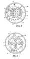
- FIG. 6 is a bottom view of a fourth embodiment of a composite condition disk with diamond and scrubbing material of the present invention.
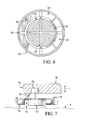
- FIG. 7 is side view of an embodiment of a composite condition assembly of the present invention.
- the invention provides a conditioning tool useful for treating the polishing surface of a polishing pad.
- the conditioning tool such as a conditioning disk, includes a base for supporting conditioning materials.
- the base supports at least two different materials an abrasive section and a polymeric section.
- the abrasive section and polymeric section act in unison or independently to provide chip manufacturers with an array of conditioning options.
- the conditioning tool is operable in a first position with only the polymeric section in contact with the polishing surface of the polishing pad.
- the polymeric section may treat the polishing surface in a variety of ways, such as cleaning or conditioning.
- the polymeric section or sections may clean the polishing surface of the polishing pad, such as the cleaning achieved with polymeric brushes or scrubbing surfaces.
- cleaning is an operation that removes debris from a polishing pad. This is most important for chemical mechanical planarization (CMP) processes that generate precipitates or residues, such as that arising from some reactive liquid processes for copper CMP.
- CMP chemical mechanical planarization
- the polymeric section may serve to condition the polishing pad.
- conditioning is any operation that affects or controls the surface characteristics of a polishing pad. As polishing pads operate at a lower pressure to planarize less robust semiconductor substrates, polymeric brushes or pads provide effective conditioning for polishing these surfaces.
- the conditioning tool is also operable in a second position with the abrasive section in contact with the polishing pad.
- the abrasive section or sections in some embodiments may act independently of the polymeric section.
- the abrasive section cuts the polishing surface of a polishing pad. The cutting can range from “kissing” the polishing surface to cut a clean-fresh surface for the polishing pad.
- a chip manufacturer uses the abrasive in a manner sufficient to provide a constant fresh surface with consistent polishing performance. Maintaining this fresh surface entails periodically cutting the polishing pad's surface before it wears to a point wherein it provide “out-of-specification” polishing characteristics.
- the polymeric section is capable of movement and downward force independent of the abrasive section. This allows the chip manufacturer to operate the polymeric section independently, the abrasive section independently or the polymeric section and abrasive section together in a simultaneous manner.
- the conditioning contains a bladder to control movement and downward force of the polymeric section independent of the abrasive section.
- the adding or subtracting a hydraulic or pneumatic fluid within the bladder controls both the movement of the bladder and downward force placed upon the polishing pad during conditioning. This movement and force controls the conditioning or cleaning that originates from the polymeric section.
- the conditioning tool may also incorporate an electromechanical device that controls movement and downward force of the polymeric section independent of the abrasive section.
- the electro-mechanical device is a solenoid that presses against a base plate of the conditioning tool.
- the method operates the conditioning tool by treating the polishing pad with a polymeric section of the conditioning tool.
- This treats the polishing surface of the polishing pad to improve the pad's polishing performance.
- This treatment usually includes cleaning or conditioning.
- manipulating the polishing tool engages an abrasive section of the conditioning tool.
- the manipulating may simply consist of pressing the tool with additional force to flex the polymeric section upward and bring the abrasive section into contact with the polishing pad.
- the polymeric section and abrasive section act independently with independent controls.
- the abrasive section conditions the polishing surface to provide the polishing pad with a conditioned surface.
- Another advantage of the invention is that the process allows for the simultaneous treating with a polymeric section and conditioning with an abrasive section in a single operation. This can provide the polishing pad with unique characteristics not possible by the independent use of either of these materials.
- the polymeric sections may include a continuous matrix derived from one of the following polymer types: acrylated urethanes; acrylated epoxys; ethylenically unsaturated organic compounds having a carboxyl, benzyl, or amide functionality; aminoplast derivatives having a pendant unsaturated carbonyl group; isocyanurate derivatives having at least one pendant acrylate group; vinyl ethers; urethanes; polyacrylamides; ethylene/ester copolymers or acid derivatives thereof; polyvinyl alcohols; polymethyl methacrylates; polysulfones; polyamides; polycarbonates; polyvinyl chloride; epoxys; copolymers of the above; or combinations thereof.
- the polymeric section is advantageously applied as a pad to a polishing pad constructed of the same polymer type.
- the polymeric section made from one of the above polymer types can condition a polishing pad that is constructed of a different polymer type.
- the polymeric sections are urethane, carbonate, amide, sulfone, vinyl chloride, acrylate, methacrylate, vinyl alcohol, ester, or acrylamide moieties.
- the polymeric section can be porous or non-porous and may contain fiber reinforcement.
- composite disks having more than one type of conditioning material are beneficial to conditioning CMP pads that use conventional abrasive slurry and especially for CMP pads that use reactive liquid slurry.
- Reactive liquid slurry used in a copper CMP process generates insoluble copper-benzotriazole (Cu-BTA) compounds during polishing.
- Cu-BTA insoluble copper-benzotriazole
- This insoluble by-product sticks to the surface of the pad and fills the polish pad groove during polishing.
- the accumulation of the insoluble by-product disturbs the normal slurry flow pattern, especially in the area where the wafer contacts the polish pad and changes the removal rate profile during the duration of the polish.
- Conventional diamond grid disks only condition the surface and cannot remove by-product within the polish pad groove.
- Brush conditioners remove the slurry by-product within the groove, but are not able to condition the pad surface.
- High pressure de-ionized (DI) water sprays are also ineffective to remove the Cu-BTA due to the stickiness and hydrophobicity of the by-product. Therefore a disk having more than one type of conditioning material can perform these multiple functions and can clean the pad more effectively.
- DI de-ionized
- the conditioning apparatus includes an oscillating condition arm 7 which applies a downward force, a rotating disk housing 12 with an attachable abrasive surface disk 3 to contact a polishing pad 9 on disk holder 5 and a mechanical drive mechanism 16 to rotate the disk and attachable brushes 4 , having bristles 14 , with an independent downforce apparatus such as, bladder 6 .
- Acceptable bladder devices include both pneumatic and hydraulic operated designs.
- An adhesive, magnetic plate or mechanical fastener is preferably used to attach disks 3 , 4 to attachable housing 5 .
- the force applied to diamond disk 3 is preferably the same as the downward force applied by the condition arm 7 .
- Cleaning solution passes through inlet 2 a and a pressurized DI water line passes through inlet 2 b through conduit 1 . Cleaning solution or pressurized DI water is used to charge the bladder 6 to increase the downward force applied on the brushes 4 .
- independent downforce apparatus 11 such as an electro-mechanical device or solenoid mounted within housing 13 on disk holder 5 , controls the pressure of conditioner base 8 on the polymeric section brushes 4 .
- downforce apparatus 11 presses the polymeric section into the polishing pad as desired to clean or condition the polishing pad 9 .
- the conditioning pad to function as a cutting abrasive 3 , a cleaning brush 4 or a combination of cutting abrasive 3 and polymeric section cleaning brush 4 with respect to polishing pad 9 .
- the cleaning brush 4 has bristles 14 to facilitate cleaning of the polishing pad 9 .
- the brush bristles 14 penetrate the pad groove 15 where insoluble slurry by-product 10 accumulates during polishing.
- a diamond disk 3 is used in conditioning a polishing pad. Mechanical force induced by the brush bristles 14 increase the rate of the chemical reaction between the cleaning solution and the slurry by-product. Also, agitation by the brush bristles 14 within the pad groove 15 decreases the hydrophobicity of the slurry by-product 10 .
- FIG. 4 illustrates another embodiment of the present invention.
- a dispenser 26 as illustrated in FIG. 4, preferably injects cleaning solution and DI water between abrasive sections 21 , 22 and polymeric section 24 containing brushes 25 .
- the polymeric section 24 can contain brushes, scrubbing material or even polishing pad material.
- the abrasive sections 21 , 22 can include diamonds, oxides, nitrides, borides or other hard material for cutting or conditioning the polishing pad. During conditioning, the abrasive sections 21 and 22 cut or remove a top layer of the polishing pad 9 .
- the abrasive sections 21 and 22 of various shapes, sizes and density can be assembled independently with variable slits 23 and 27 to form the diamond sections. The particle size and distribution of the abrasive controls the conditioning characteristics of the conditioner.
- FIG. 4 has the polymeric section in the center and the abrasive sections on the outside circumference.
- FIG. 5 illustrates an alternative embodiment wherein the section configuration of conditioning tool 34 has polymeric section 33 on the outer circumference and abrasive sections 31 , 36 in the center with variable slits 30 and 35 . Open slits 38 , in base 37 , provide a path for the cleaning solution and DI water to flow within the abrasive section and polymeric section, such as brushes.
- FIG. 6 illustrates yet another embodiment for disk configuration wherein various polymers, such as porous scrubbing materials 61 , 67 are in the center with a cleaning solution dispenser 63 and abrasive sections 62 , 68 , such as diamond disks, with variable slits 65 and 66 .
- the conditioner tool 64 operates with various configurations and combinations of brushes, diamond disks, scrubbing materials and open slits.
- the composite disk of the present invention can condition the pad surface and clean the pad groove at the same time or can be segmented by condition recipe to perform ex situ or in situ conditioning or can be used to perform a combination of ex situ conditioning followed by in situ conditioning.
- Table I lists the various combination of conditioning materials that may be used for in situ or ex situ conditioning with the conditioning disks of the present invention.
- TABLE 1 Ex-situ conditioning options In-situ conditioning options No ex-situ conditioning No in-situ conditioning Abrasive only Abrasive only Brush only Brush only Scrubbing material only Scrubbing material only Abrasive and brush Abrasive and brush Abrasive and scrubbing materials Abrasive and scrubbing materials Brush and scrubbing materials only Brush and scrubbing materials only Abrasive, brush and scrubbing Abrasive, brush and scrubbing Abrasive, brush and scrubbing
- FIG. 7 illustrates another embodiment of a condition assembly 76 having a cleaning solution dispenser 75 and a composite condition disk with an abrasive section 74 , such as a diamond grid and a polymeric section 72 such as a scrubbing material.
- the downforce applied to polymeric section 72 such as brushes or scrubbers may be kept equal to the downforce (directional arrow “1”) applied by condition arm 70 .
- the polymeric section 72 may include a combination of brushes and scrubbers or a combination of brushes and polymeric pads. As the force against polymeric section 72 increases, the abrasive section 74 begins to engage.
- the flexibility of polymeric section 72 allows for this section to act independently of the abrasive section 74 or in combination when the pressure deflects the polymeric section 72 sufficiently.
- the slits between the abrasive section 74 and opening 71 between the abrasive section and the polymeric section 72 , such as a brush or scrubbing material are open and cleaning solution and DI water can flow down from nozzle 75 .
- a flow guard 77 is positioned around the circumference of the composite disk to prevent cleaning solution from overflowing due to centrifugal force.
- the height of the protruding brush or scrubber 73 is preferably matched with depth of the pad groove.
- the cleaning solution nozzle 75 is preferably positioned directly above the open slit 71 .
- the diameter of the condition disk is preferably from about 2 inches to about 10 inches and, more preferably, from about 4 inches to about 6 inches.
- the condition disk diameter is preferably from about 4 inches to about 12 inches and, more preferably, from about 4 inches to about 8 inches.
- all diamond sections should preferably be about the same size, height and density. Positioning the nozzle dispenser over the condition disk allows most of the cleaning solution to go within the condition area and speeds up the removal rate of Cu-BTA during conditioning.
- a scrubbing material in conjunction with an abrasive disk or brushes, also provides a more efficient way to remove slurry by-product from the surface and within the groove of the polish pad.
- Some examples of preferred scrubbing material are micro-porous polymeric materials, porous polyurethane impregnated felts, closed cell polyurethane foams and solid polymers having macro and micro texture.
- the scrubbing materials are not limited to thermoplastics and thermosets.
- the conditioning tool of claim 1 includes openings for transferring fluids to the polishing pad. These openings reduce the need to inject cleaning solution from the side and can in turn reduce the amount of distilled water and cleaning solution used in polishing. By cleaning the polishing pad more effectively, the conditioning disks of the present invention also reduce the glazing effect that occurs with conventional CMP polishing systems.
Abstract
A conditioning tool is useful for treating the polishing surface of a polishing pad. The tool has a base for supporting conditioning materials. The base has an abrasive section for cutting a polishing surface of the polishing pad and a polymeric section for treating the polishing surface of the polishing pad. The polymeric section is operable in a first position with only the polymeric section in contact with the polishing surface of the polishing pad and operable in a second position with the abrasive section in contact with the polishing surface of the polishing pad.
Description
- This application is a continuation-in-part of U.S. application Ser. No. 10/115,476, filed Apr. 2, 2002, now abandoned.
- The present invention relates, in general, to a system for cleaning and conditioning polish pads used to polish silicon wafers and semiconductors and, more particularly, to pad cleaning during polishing and pad conditioning and cleaning.
- Silicon wafers are commonly used as a base on which multi-level integrated circuits are fabricated. Integrated circuits on semiconductor wafers are manufactured with a layer of an insulating layer or semi-conductive or conductive metal substrate layer. This layer can be a dielectric, such as, silica including SiO 2 and TEOS. It can also be a low K dielectric, poly-silicon or metal such as tungsten, aluminum, copper and platinum.
- A series of deposition and etch steps are required to form a multi-level pattern on a semiconductor wafer. Silicon wafers for the semiconductor industry must possess a high degree of surface perfection before they can be useful in the device fabrication process. A non-planar silicon wafer surface during the manufacturing process causes a focusing problem for photolithography and results in lower yield and decreases performance of the semiconductor device.
- A polishing system known as CMP, referred to as either or both, chemical-mechanical planarization and chemical-mechanical polishing of non-planar wafer is utilized in a conventional process. The CMP process is used to planarize the insulating layer on a silicon wafer. A CMP process can be used for an insulating layer whether it is a dielectric material, conductive metal or semi-conductive layer. The CMP process utilizes different polishing pads and polishing compositions or slurries. Further details of CMP polishing features and operation of a polishing apparatus for a CMP process may be found in U.S. Pat. No. 5,738,574.
- In a CMP process, the wafer is pressed against a moving polishing pad. In a CMP process, the silicon wafer is bathed or rinsed in a polishing slurry in conjunction with an elastomeric pad that is pressed against the substrate and rotated such that the slurry particles are pressed against the substrate under load. The lateral motion of the pad causes the slurry particles to move across the substrate surface, resulting in wear, or volumetric removal of the substrate surface. Ideally, this process results in the selective erosion of projecting surface features so that when the process is completed a plane surface is produced down to the finest level of detail.
- However, the CMP process generates heat due to chemical reaction and mechanical friction, which degrades the surface topography of the pad. Also, by-product of the slurry from wafer-substrate reaction produces slurry waste, which accumulates on the pad or within the pad groove and prevents even distribution of fresh slurry and degrades pad asperities. The combination of the above reactions can produce glazing of the pad. Glazing is referred to a surface phenomenon that occurs when the pad temperature during CMP is at or exceeds the pad glass transition temperature and deforms the pad material and traps slurry by-products. These slurry by-products become partially or fully fused into the surface of the pad. Glazing decreases pad asperity and increases wafer non-uniformity and defects on the wafer.
- The conventional CMP process uses a conditioning apparatus, as disclosed in U.S. Pat. No. 6,217,429 or similar device using a diamond or abrasive material on a disk in contact with the polish pad to remove glaze material and by-product of CMP waste. On a buffing pad or softer pad, a brush is used instead of a diamond disk. Deionized (DI) water is normally used during pad conditioning to help lubricate the pad and to remove debris from the pad. A high-pressure DI sprayer is sometimes used to speed up the cleaning process. For metal CMP and especially for copper CMP, cleaning solution is used to speed up the cleaning and decontamination of slurry by-products from the surface of the pad.
- To perform pad conditioning with a diamond disk and clean the pad groove with brushes at the same time, two separate condition arms or a condition arm with two different disks are necessary. However, having separate condition arms or multiple disks increases the cost of the polishing apparatus. Accordingly, it has been desired to develop a method and apparatus for polishing a semiconductor wafer that addresses the problems above and reduces glazing and the steps and costs of polishing semiconductor wafers.
- The invention provides a conditioning tool useful for treating the polishing surface of a polishing pad, comprising: a base for supporting conditioning materials; the base having an abrasive section for cutting a polishing surface of the polishing pad; and a polymeric section for treating the polishing surface of the polishing pad, the polymeric section being operable in a first position with only the polymeric section in contact with the polishing surface of the polishing pad and operable in a second position with the abrasive section in contact with the polishing surface of the polishing pad.
- In addition, the invention provides a method of treating the surface of a polishing pad with a conditioning tool comprising the steps of: treating the polishing pad with a polymeric section of a conditioning tool to treat a polishing surface of the polishing pad; manipulating the polishing tool to engage an abrasive section of the conditioning tool; and conditioning the polishing pad with the abrasive section of the conditioning tool to provide the polishing surface of the polishing pad with a conditioned surface.
- FIG. 1 is a side view of an embodiment of the conditioning assembly of the invention illustrated in FIG. 1;
- FIG. 2 is a side view of a composite pad with two independent downward forces applied to the pad;
- FIG. 3 is an exploded side view of the composite pad contact area “3” illustrated in FIG. 2;
- FIG. 4 is a bottom view of a second embodiment of a composite condition disk with diamond and brush condition of the present invention;
- FIG. 5 is a bottom view of a third embodiment of a composite condition disk with variable brush slits and diamond configuration of the present invention;
- FIG. 6 is a bottom view of a fourth embodiment of a composite condition disk with diamond and scrubbing material of the present invention; and
- FIG. 7 is side view of an embodiment of a composite condition assembly of the present invention.
- The invention provides a conditioning tool useful for treating the polishing surface of a polishing pad. The conditioning tool, such as a conditioning disk, includes a base for supporting conditioning materials. The base supports at least two different materials an abrasive section and a polymeric section. The abrasive section and polymeric section act in unison or independently to provide chip manufacturers with an array of conditioning options.
- The conditioning tool is operable in a first position with only the polymeric section in contact with the polishing surface of the polishing pad. The polymeric section may treat the polishing surface in a variety of ways, such as cleaning or conditioning. The polymeric section or sections may clean the polishing surface of the polishing pad, such as the cleaning achieved with polymeric brushes or scrubbing surfaces. For purposes of this specification, cleaning is an operation that removes debris from a polishing pad. This is most important for chemical mechanical planarization (CMP) processes that generate precipitates or residues, such as that arising from some reactive liquid processes for copper CMP. In addition, the polymeric section may serve to condition the polishing pad. For purposes of this specification, conditioning is any operation that affects or controls the surface characteristics of a polishing pad. As polishing pads operate at a lower pressure to planarize less robust semiconductor substrates, polymeric brushes or pads provide effective conditioning for polishing these surfaces.
- The conditioning tool is also operable in a second position with the abrasive section in contact with the polishing pad. The abrasive section or sections in some embodiments may act independently of the polymeric section. The abrasive section cuts the polishing surface of a polishing pad. The cutting can range from “kissing” the polishing surface to cut a clean-fresh surface for the polishing pad. Typically, a chip manufacturer uses the abrasive in a manner sufficient to provide a constant fresh surface with consistent polishing performance. Maintaining this fresh surface entails periodically cutting the polishing pad's surface before it wears to a point wherein it provide “out-of-specification” polishing characteristics.
- Most advantageously, the polymeric section is capable of movement and downward force independent of the abrasive section. This allows the chip manufacturer to operate the polymeric section independently, the abrasive section independently or the polymeric section and abrasive section together in a simultaneous manner.
- Advantageously, the conditioning contains a bladder to control movement and downward force of the polymeric section independent of the abrasive section. The adding or subtracting a hydraulic or pneumatic fluid within the bladder controls both the movement of the bladder and downward force placed upon the polishing pad during conditioning. This movement and force controls the conditioning or cleaning that originates from the polymeric section. Optionally, the conditioning tool may also incorporate an electromechanical device that controls movement and downward force of the polymeric section independent of the abrasive section. Advantageously, the electro-mechanical device is a solenoid that presses against a base plate of the conditioning tool.
- The method operates the conditioning tool by treating the polishing pad with a polymeric section of the conditioning tool. This treats the polishing surface of the polishing pad to improve the pad's polishing performance. This treatment usually includes cleaning or conditioning. Then manipulating the polishing tool engages an abrasive section of the conditioning tool. The manipulating may simply consist of pressing the tool with additional force to flex the polymeric section upward and bring the abrasive section into contact with the polishing pad. Most advantageously, however, the polymeric section and abrasive section act independently with independent controls. After manipulating the polishing pad, the abrasive section conditions the polishing surface to provide the polishing pad with a conditioned surface.
- Operating the polymeric sections independent of the abrasive sections allows a chip manufacturer to treat the polishing pad with the polymeric section for more than one polishing cycle before conditioning the polishing surface with the abrasive section. This periodic use of the abrasive can provide a substantial increase to the polishing pad's useful life. For example, for some pads it may be possible to clean the polishing pad for three cycles and then only condition the pad with the abrasive every fourth cycle.
- Another advantage of the invention is that the process allows for the simultaneous treating with a polymeric section and conditioning with an abrasive section in a single operation. This can provide the polishing pad with unique characteristics not possible by the independent use of either of these materials.
- The polymeric sections may include a continuous matrix derived from one of the following polymer types: acrylated urethanes; acrylated epoxys; ethylenically unsaturated organic compounds having a carboxyl, benzyl, or amide functionality; aminoplast derivatives having a pendant unsaturated carbonyl group; isocyanurate derivatives having at least one pendant acrylate group; vinyl ethers; urethanes; polyacrylamides; ethylene/ester copolymers or acid derivatives thereof; polyvinyl alcohols; polymethyl methacrylates; polysulfones; polyamides; polycarbonates; polyvinyl chloride; epoxys; copolymers of the above; or combinations thereof. The polymeric section is advantageously applied as a pad to a polishing pad constructed of the same polymer type. Alternatively, the polymeric section made from one of the above polymer types can condition a polishing pad that is constructed of a different polymer type.
- Most advantageously, the polymeric sections are urethane, carbonate, amide, sulfone, vinyl chloride, acrylate, methacrylate, vinyl alcohol, ester, or acrylamide moieties. In addition, the polymeric section can be porous or non-porous and may contain fiber reinforcement.
- It has been found that composite disks having more than one type of conditioning material are beneficial to conditioning CMP pads that use conventional abrasive slurry and especially for CMP pads that use reactive liquid slurry. Reactive liquid slurry used in a copper CMP process generates insoluble copper-benzotriazole (Cu-BTA) compounds during polishing. This insoluble by-product sticks to the surface of the pad and fills the polish pad groove during polishing. Furthermore, the accumulation of the insoluble by-product disturbs the normal slurry flow pattern, especially in the area where the wafer contacts the polish pad and changes the removal rate profile during the duration of the polish. Conventional diamond grid disks only condition the surface and cannot remove by-product within the polish pad groove. Brush conditioners remove the slurry by-product within the groove, but are not able to condition the pad surface. High pressure de-ionized (DI) water sprays are also ineffective to remove the Cu-BTA due to the stickiness and hydrophobicity of the by-product. Therefore a disk having more than one type of conditioning material can perform these multiple functions and can clean the pad more effectively.
- During a copper CMP process using reactive liquid slurry, the removal rate of copper decreases as polish time increases due to by-product buildup on the surface and within the pad groove. Using in-situ conditions during polishing with a diamond conditioner does not efficiently remove the insoluble by-product. However, the use of a brush or scrubbing material removes the insoluble by-product within the groove of the pad more efficiently than a diamond conditioner. The present invention addresses this cleaning problem associated with the copper CMP process and reduces the consumption of DI water and cleaning solution during polishing.
- One embodiment of the conditioning apparatus of the present invention is illustrated in FIG. 1. The conditioning apparatus includes an
oscillating condition arm 7 which applies a downward force, arotating disk housing 12 with an attachableabrasive surface disk 3 to contact apolishing pad 9 ondisk holder 5 and amechanical drive mechanism 16 to rotate the disk andattachable brushes 4, havingbristles 14, with an independent downforce apparatus such as,bladder 6. Acceptable bladder devices include both pneumatic and hydraulic operated designs. An adhesive, magnetic plate or mechanical fastener is preferably used to attachdisks attachable housing 5. The force applied todiamond disk 3 is preferably the same as the downward force applied by thecondition arm 7. Cleaning solution passes throughinlet 2 a and a pressurized DI water line passes throughinlet 2 b throughconduit 1. Cleaning solution or pressurized DI water is used to charge thebladder 6 to increase the downward force applied on thebrushes 4. - Referring to FIG. 2, independent downforce apparatus 11, such as an electro-mechanical device or solenoid mounted within
housing 13 ondisk holder 5, controls the pressure of conditioner base 8 on the polymeric section brushes 4. During operation, downforce apparatus 11 presses the polymeric section into the polishing pad as desired to clean or condition thepolishing pad 9. This allows the conditioning pad to function as a cutting abrasive 3, a cleaningbrush 4 or a combination of cutting abrasive 3 and polymericsection cleaning brush 4 with respect to polishingpad 9. Advantageously, the cleaningbrush 4 hasbristles 14 to facilitate cleaning of thepolishing pad 9. - As illustrated in FIG. 3, the brush bristles 14 penetrate the
pad groove 15 where insoluble slurry by-product 10 accumulates during polishing. Adiamond disk 3 is used in conditioning a polishing pad. Mechanical force induced by the brush bristles 14 increase the rate of the chemical reaction between the cleaning solution and the slurry by-product. Also, agitation by the brush bristles 14 within thepad groove 15 decreases the hydrophobicity of the slurry by-product 10. - FIG. 4 illustrates another embodiment of the present invention. In order to enhance cleaning of
conditioning tool 20, adispenser 26, as illustrated in FIG. 4, preferably injects cleaning solution and DI water betweenabrasive sections polymeric section 24 containing brushes 25. Thepolymeric section 24 can contain brushes, scrubbing material or even polishing pad material. - The
abrasive sections abrasive sections polishing pad 9. Theabrasive sections variable slits - The embodiment in FIG. 4 has the polymeric section in the center and the abrasive sections on the outside circumference. FIG. 5 illustrates an alternative embodiment wherein the section configuration of
conditioning tool 34 haspolymeric section 33 on the outer circumference andabrasive sections variable slits Open slits 38, inbase 37, provide a path for the cleaning solution and DI water to flow within the abrasive section and polymeric section, such as brushes. - FIG. 6 illustrates yet another embodiment for disk configuration wherein various polymers, such as
porous scrubbing materials cleaning solution dispenser 63 andabrasive sections variable slits conditioner tool 64 operates with various configurations and combinations of brushes, diamond disks, scrubbing materials and open slits. The composite disk of the present invention, can condition the pad surface and clean the pad groove at the same time or can be segmented by condition recipe to perform ex situ or in situ conditioning or can be used to perform a combination of ex situ conditioning followed by in situ conditioning. For example, Table I lists the various combination of conditioning materials that may be used for in situ or ex situ conditioning with the conditioning disks of the present invention.TABLE 1 Ex-situ conditioning options In-situ conditioning options No ex-situ conditioning No in-situ conditioning Abrasive only Abrasive only Brush only Brush only Scrubbing material only Scrubbing material only Abrasive and brush Abrasive and brush Abrasive and scrubbing materials Abrasive and scrubbing materials Brush and scrubbing materials only Brush and scrubbing materials only Abrasive, brush and scrubbing Abrasive, brush and scrubbing - FIG. 7 illustrates another embodiment of a
condition assembly 76 having acleaning solution dispenser 75 and a composite condition disk with anabrasive section 74, such as a diamond grid and apolymeric section 72 such as a scrubbing material. The downforce applied topolymeric section 72, such as brushes or scrubbers may be kept equal to the downforce (directional arrow “1”) applied bycondition arm 70. In addition, thepolymeric section 72 may include a combination of brushes and scrubbers or a combination of brushes and polymeric pads. As the force againstpolymeric section 72 increases, theabrasive section 74 begins to engage. The flexibility ofpolymeric section 72 allows for this section to act independently of theabrasive section 74 or in combination when the pressure deflects thepolymeric section 72 sufficiently. - As illustrated in FIG. 7, the slits between the
abrasive section 74 andopening 71 between the abrasive section and thepolymeric section 72, such as a brush or scrubbing material are open and cleaning solution and DI water can flow down fromnozzle 75. Aflow guard 77 is positioned around the circumference of the composite disk to prevent cleaning solution from overflowing due to centrifugal force. The height of the protruding brush orscrubber 73 is preferably matched with depth of the pad groove. Thecleaning solution nozzle 75 is preferably positioned directly above theopen slit 71. - For polishing a 6 or 8 inch wafer, the diameter of the condition disk is preferably from about 2 inches to about 10 inches and, more preferably, from about 4 inches to about 6 inches. For 12 inch wafers, the condition disk diameter is preferably from about 4 inches to about 12 inches and, more preferably, from about 4 inches to about 8 inches. To maintain even pad asperities during conditioning, all diamond sections should preferably be about the same size, height and density. Positioning the nozzle dispenser over the condition disk allows most of the cleaning solution to go within the condition area and speeds up the removal rate of Cu-BTA during conditioning.
- Using a scrubbing material in conjunction with an abrasive disk or brushes, also provides a more efficient way to remove slurry by-product from the surface and within the groove of the polish pad. Some examples of preferred scrubbing material are micro-porous polymeric materials, porous polyurethane impregnated felts, closed cell polyurethane foams and solid polymers having macro and micro texture. One of ordinary skill in the art will recognize, however, that the scrubbing materials are not limited to thermoplastics and thermosets.
- Optionally, the conditioning tool of
claim 1 includes openings for transferring fluids to the polishing pad. These openings reduce the need to inject cleaning solution from the side and can in turn reduce the amount of distilled water and cleaning solution used in polishing. By cleaning the polishing pad more effectively, the conditioning disks of the present invention also reduce the glazing effect that occurs with conventional CMP polishing systems. - It is contemplated that numerous modifications may be made to the conditioning apparatus of the present invention without departing from the spirit and scope of the claims. Although the composite conditioning disk is illustrated on a rotary CMP tool, one of ordinary skill would recognize that the scope of this invention can be applied to linear, orbital and web based CMP polishers as well. Accordingly, while the present invention has been described herein in relation to several embodiments, the foregoing disclosure is not intended or to be construed to limit the present invention or otherwise to exclude any such other embodiments, arrangements, variations, or modifications and equivalent arrangements. Rather, the present invention is limited only by the claims appended hereto and the equivalents thereof.
Claims (10)
1. A conditioning tool useful for treating the polishing surface of a polishing pad, comprising:
a base for supporting conditioning materials; the base having an abrasive section for cutting a polishing surface of the polishing pad; and a polymeric section for treating the polishing surface of the polishing pad, the polymeric section being operable in a first position with only the polymeric section in contact with the polishing surface of the polishing pad and operable in a second position with the abrasive section in contact with the polishing surface of the polishing pad.
2. The conditioning tool of claim 1 wherein a bladder controls movement and downward force of the polymeric section independent of the abrasive section.
3. The conditioning tool of claim 1 wherein an electromechanical device controls movement and downward force of the polymeric section independent of the abrasive section.
4. The conditioning tool of claim 1 wherein the base includes openings for transferring fluids to the polishing pad.
5. A conditioning tool useful for treating the polishing surface of a polishing pad, comprising:
a base for supporting conditioning materials; the base having an abrasive section for cutting a polishing surface of a polishing pad; and a polymeric section for treating the polishing surface of the polishing pad, the polymeric section being capable of movement and downward force independent of the abrasive section and being operable in a first position with only the polymeric section in contact with the polishing surface of the polishing pad and operable in a second position with the abrasive section in contact with the polishing surface of the polishing pad.
6. A method of treating the surface of a polishing pad with a conditioning tool comprising the steps of:
treating the polishing pad with a polymeric section of the conditioning tool to treat a polishing surface of the polishing pad;
manipulating the conditioning tool to engage an abrasive section of the conditioning tool; and
conditioning the polishing pad with the abrasive section of the conditioning tool to provide the polishing surface of the polishing pad with a conditioned surface.
7. The method of claim 6 including the additional step of treating the polishing pad with the polymeric section for more than one polishing cycle before conditioning the polishing surface with the abrasive section.
8. The method of claim 6 wherein the treating and the conditioning occur as a simultaneous operation.
9. The method of claim 6 wherein the treating the polishing pad with the polymeric section cleans the polishing surface of the polishing pad with brushes.
10. The method of claim 6 wherein the treating the polishing pad with the polymeric section conditions the polishing surface of the polishing pad with a polymeric pad.
Priority Applications (1)
| Application Number | Priority Date | Filing Date | Title |
|---|---|---|---|
| US10/405,542 US20030190874A1 (en) | 2002-04-02 | 2003-04-02 | Composite conditioning tool |
Applications Claiming Priority (2)
| Application Number | Priority Date | Filing Date | Title |
|---|---|---|---|
| US11547602A | 2002-04-02 | 2002-04-02 | |
| US10/405,542 US20030190874A1 (en) | 2002-04-02 | 2003-04-02 | Composite conditioning tool |
Related Parent Applications (1)
| Application Number | Title | Priority Date | Filing Date |
|---|---|---|---|
| US11547602A Continuation-In-Part | 2002-04-02 | 2002-04-02 |
Publications (1)
| Publication Number | Publication Date |
|---|---|
| US20030190874A1 true US20030190874A1 (en) | 2003-10-09 |
Family
ID=28673778
Family Applications (1)
| Application Number | Title | Priority Date | Filing Date |
|---|---|---|---|
| US10/405,542 Abandoned US20030190874A1 (en) | 2002-04-02 | 2003-04-02 | Composite conditioning tool |
Country Status (4)
| Country | Link |
|---|---|
| US (1) | US20030190874A1 (en) |
| AU (1) | AU2003218477A1 (en) |
| TW (1) | TW200400866A (en) |
| WO (1) | WO2003084715A1 (en) |
Cited By (17)
| Publication number | Priority date | Publication date | Assignee | Title |
|---|---|---|---|---|
| US7033253B2 (en) * | 2004-08-12 | 2006-04-25 | Micron Technology, Inc. | Polishing pad conditioners having abrasives and brush elements, and associated systems and methods |
| US20060121837A1 (en) * | 2004-12-03 | 2006-06-08 | Asahi Sunac Corporation | Dressing method for polishing pad |
| US7170190B1 (en) * | 2003-12-16 | 2007-01-30 | Lam Research Corporation | Apparatus for oscillating a head and methods for implementing the same |
| US20070077870A1 (en) * | 2005-08-26 | 2007-04-05 | Tokyo Seimitsu Co., Ltd. | Pad conditioner, pad conditioning method, and polishing apparatus |
| US20070087672A1 (en) * | 2005-10-19 | 2007-04-19 | Tbw Industries, Inc. | Apertured conditioning brush for chemical mechanical planarization systems |
| US20070161338A1 (en) * | 2005-11-24 | 2007-07-12 | Tokyo Seimitsu Co., Ltd. | Wafer polishing apparatus and wafer polishing method |
| US20080003930A1 (en) * | 2005-08-30 | 2008-01-03 | Tokyo Seimitsu Co., Ltd. | Pad conditioner, pad conditioning method, and polishing apparatus |
| JP2009012130A (en) * | 2007-07-05 | 2009-01-22 | Sharp Corp | Chemical mechanical polishing device |
| US20090104863A1 (en) * | 2007-10-17 | 2009-04-23 | Chun-Liang Lin | Pad conditioner for chemical mechanical polishing |
| EP2377423A1 (en) * | 2010-04-14 | 2011-10-19 | Rolls-Royce plc | Apparatus and method for applying a fluid to a component |
| US20160074995A1 (en) * | 2014-09-11 | 2016-03-17 | Kinik Company | Chemical mechanical polishing conditioner with brushes |
| US20160233101A1 (en) * | 2015-02-05 | 2016-08-11 | Kabushiki Kaisha Toshiba | Polishing apparatus, polishing method, and semiconductor manufacturing method |
| US20180099376A1 (en) * | 2016-10-06 | 2018-04-12 | Shinhan Diamond Ind. Co., Ltd. | Attachment removing device for diamond tool |
| US20180243882A1 (en) * | 2015-10-29 | 2018-08-30 | Sk Siltron Co., Ltd. | Dressing apparatus and wafer polishing apparatus comprising same |
| WO2020234346A1 (en) * | 2019-05-20 | 2020-11-26 | Hartmetall-Werkzeugfabrik Paul Horn Gmbh | Combined grinding and brushing device |
| US10857651B2 (en) * | 2017-11-20 | 2020-12-08 | Taiwan Semiconductor Manufacturing Company Ltd. | Apparatus of chemical mechanical polishing and operating method thereof |
| US11787012B2 (en) * | 2019-10-31 | 2023-10-17 | Taiwan Semiconductor Manufacturing Co., Ltd. | Conditioner disk, chemical mechanical polishing device, and method |
Families Citing this family (3)
| Publication number | Priority date | Publication date | Assignee | Title |
|---|---|---|---|---|
| US8920214B2 (en) * | 2011-07-12 | 2014-12-30 | Chien-Min Sung | Dual dressing system for CMP pads and associated methods |
| WO2018063242A1 (en) * | 2016-09-29 | 2018-04-05 | Intel Corporation | Chemical-mechanical planarization (cmp) pad conditioner brush-and-abrasive hybrid for multi-step, preparation- and restoration-conditioning process of cmp pad |
| CN109483403A (en) * | 2018-12-25 | 2019-03-19 | 上海致领半导体科技发展有限公司 | A kind of polishing pad brush with grooming function |
Citations (5)
| Publication number | Priority date | Publication date | Assignee | Title |
|---|---|---|---|---|
| US5902173A (en) * | 1996-03-19 | 1999-05-11 | Yamaha Corporation | Polishing machine with efficient polishing and dressing |
| US6135868A (en) * | 1998-02-11 | 2000-10-24 | Applied Materials, Inc. | Groove cleaning device for chemical-mechanical polishing |
| US6193587B1 (en) * | 1999-10-01 | 2001-02-27 | Taiwan Semicondutor Manufacturing Co., Ltd | Apparatus and method for cleansing a polishing pad |
| US6270396B1 (en) * | 1998-07-06 | 2001-08-07 | Canon Kabushika Kaisha | Conditioning apparatus and conditioning method |
| US6340326B1 (en) * | 2000-01-28 | 2002-01-22 | Lam Research Corporation | System and method for controlled polishing and planarization of semiconductor wafers |
Family Cites Families (3)
| Publication number | Priority date | Publication date | Assignee | Title |
|---|---|---|---|---|
| US6200199B1 (en) * | 1998-03-31 | 2001-03-13 | Applied Materials, Inc. | Chemical mechanical polishing conditioner |
| US6086460A (en) * | 1998-11-09 | 2000-07-11 | Lam Research Corporation | Method and apparatus for conditioning a polishing pad used in chemical mechanical planarization |
| KR100546288B1 (en) * | 1999-04-10 | 2006-01-26 | 삼성전자주식회사 | Chemical-mechanical polishing CMP apparatus |
-
2003
- 2003-04-02 WO PCT/US2003/009825 patent/WO2003084715A1/en not_active Application Discontinuation
- 2003-04-02 US US10/405,542 patent/US20030190874A1/en not_active Abandoned
- 2003-04-02 AU AU2003218477A patent/AU2003218477A1/en not_active Abandoned
- 2003-04-02 TW TW092107504A patent/TW200400866A/en unknown
Patent Citations (5)
| Publication number | Priority date | Publication date | Assignee | Title |
|---|---|---|---|---|
| US5902173A (en) * | 1996-03-19 | 1999-05-11 | Yamaha Corporation | Polishing machine with efficient polishing and dressing |
| US6135868A (en) * | 1998-02-11 | 2000-10-24 | Applied Materials, Inc. | Groove cleaning device for chemical-mechanical polishing |
| US6270396B1 (en) * | 1998-07-06 | 2001-08-07 | Canon Kabushika Kaisha | Conditioning apparatus and conditioning method |
| US6193587B1 (en) * | 1999-10-01 | 2001-02-27 | Taiwan Semicondutor Manufacturing Co., Ltd | Apparatus and method for cleansing a polishing pad |
| US6340326B1 (en) * | 2000-01-28 | 2002-01-22 | Lam Research Corporation | System and method for controlled polishing and planarization of semiconductor wafers |
Cited By (27)
| Publication number | Priority date | Publication date | Assignee | Title |
|---|---|---|---|---|
| US7170190B1 (en) * | 2003-12-16 | 2007-01-30 | Lam Research Corporation | Apparatus for oscillating a head and methods for implementing the same |
| US7033253B2 (en) * | 2004-08-12 | 2006-04-25 | Micron Technology, Inc. | Polishing pad conditioners having abrasives and brush elements, and associated systems and methods |
| US20060121837A1 (en) * | 2004-12-03 | 2006-06-08 | Asahi Sunac Corporation | Dressing method for polishing pad |
| US20070077870A1 (en) * | 2005-08-26 | 2007-04-05 | Tokyo Seimitsu Co., Ltd. | Pad conditioner, pad conditioning method, and polishing apparatus |
| US7670209B2 (en) * | 2005-08-26 | 2010-03-02 | Tokyo Seimitsu Co., Ltd. | Pad conditioner, pad conditioning method, and polishing apparatus |
| US20080003930A1 (en) * | 2005-08-30 | 2008-01-03 | Tokyo Seimitsu Co., Ltd. | Pad conditioner, pad conditioning method, and polishing apparatus |
| US7354337B2 (en) * | 2005-08-30 | 2008-04-08 | Tokyo Seimitsu Co., Ltd. | Pad conditioner, pad conditioning method, and polishing apparatus |
| US20080090499A1 (en) * | 2005-08-30 | 2008-04-17 | Tokyo Seimitsu Co., Ltd. | Pad conditioner, pad conditioning method, and polishing apparatus |
| US7731569B2 (en) | 2005-08-30 | 2010-06-08 | Tokyo Seimitsu Co., Ltd. | Pad conditioner, pad conditioning method, and polishing apparatus |
| JP2009512569A (en) * | 2005-10-19 | 2009-03-26 | ティービーダブリュ インダストリーズ インク. | Aperture adjustment brush for chemical mechanical polishing systems |
| US20070087672A1 (en) * | 2005-10-19 | 2007-04-19 | Tbw Industries, Inc. | Apertured conditioning brush for chemical mechanical planarization systems |
| US8043140B2 (en) | 2005-11-24 | 2011-10-25 | Tokyo Seimitsu Co., Ltd. | Wafer polishing apparatus and wafer polishing method |
| US20070161338A1 (en) * | 2005-11-24 | 2007-07-12 | Tokyo Seimitsu Co., Ltd. | Wafer polishing apparatus and wafer polishing method |
| US7753761B2 (en) * | 2005-11-24 | 2010-07-13 | Tokyo Seimitsu Co., Ltd. | Wafer polishing apparatus and wafer polishing method |
| JP2009012130A (en) * | 2007-07-05 | 2009-01-22 | Sharp Corp | Chemical mechanical polishing device |
| US20090104863A1 (en) * | 2007-10-17 | 2009-04-23 | Chun-Liang Lin | Pad conditioner for chemical mechanical polishing |
| EP2377423A1 (en) * | 2010-04-14 | 2011-10-19 | Rolls-Royce plc | Apparatus and method for applying a fluid to a component |
| GB2479559B (en) * | 2010-04-14 | 2012-07-25 | Rolls Royce Plc | Apparatus and method for applying a fluid to a component |
| US20160074995A1 (en) * | 2014-09-11 | 2016-03-17 | Kinik Company | Chemical mechanical polishing conditioner with brushes |
| US20160233101A1 (en) * | 2015-02-05 | 2016-08-11 | Kabushiki Kaisha Toshiba | Polishing apparatus, polishing method, and semiconductor manufacturing method |
| US9902038B2 (en) * | 2015-02-05 | 2018-02-27 | Toshiba Memory Corporation | Polishing apparatus, polishing method, and semiconductor manufacturing method |
| US20180243882A1 (en) * | 2015-10-29 | 2018-08-30 | Sk Siltron Co., Ltd. | Dressing apparatus and wafer polishing apparatus comprising same |
| US10737366B2 (en) * | 2015-10-29 | 2020-08-11 | Sk Siltron Co., Ltd. | Dressing apparatus and wafer polishing apparatus comprising same |
| US20180099376A1 (en) * | 2016-10-06 | 2018-04-12 | Shinhan Diamond Ind. Co., Ltd. | Attachment removing device for diamond tool |
| US10857651B2 (en) * | 2017-11-20 | 2020-12-08 | Taiwan Semiconductor Manufacturing Company Ltd. | Apparatus of chemical mechanical polishing and operating method thereof |
| WO2020234346A1 (en) * | 2019-05-20 | 2020-11-26 | Hartmetall-Werkzeugfabrik Paul Horn Gmbh | Combined grinding and brushing device |
| US11787012B2 (en) * | 2019-10-31 | 2023-10-17 | Taiwan Semiconductor Manufacturing Co., Ltd. | Conditioner disk, chemical mechanical polishing device, and method |
Also Published As
| Publication number | Publication date |
|---|---|
| WO2003084715A1 (en) | 2003-10-16 |
| AU2003218477A1 (en) | 2003-10-20 |
| TW200400866A (en) | 2004-01-16 |
Similar Documents
| Publication | Publication Date | Title |
|---|---|---|
| US20030190874A1 (en) | Composite conditioning tool | |
| US5910043A (en) | Polishing pad for chemical-mechanical planarization of a semiconductor wafer | |
| USRE39195E1 (en) | Polishing pad refurbisher for in situ, real-time conditioning and cleaning of a polishing pad used in chemical-mechanical polishing of microelectronic substrates | |
| US6193587B1 (en) | Apparatus and method for cleansing a polishing pad | |
| US7575503B2 (en) | Vacuum-assisted pad conditioning system | |
| US8485863B2 (en) | Polishing liquids for activating and/or conditioning fixed abrasive polishing pads, and associated systems and methods | |
| US6722943B2 (en) | Planarizing machines and methods for dispensing planarizing solutions in the processing of microelectronic workpieces | |
| EP0878269B1 (en) | Apparatus for conditioning polishing pads | |
| US6022266A (en) | In-situ pad conditioning process for CMP | |
| US6398627B1 (en) | Slurry dispenser having multiple adjustable nozzles | |
| US6769968B2 (en) | Interchangeable conditioning disk apparatus | |
| US20070087672A1 (en) | Apertured conditioning brush for chemical mechanical planarization systems | |
| US6179693B1 (en) | In-situ/self-propelled polishing pad conditioner and cleaner | |
| US20040121710A1 (en) | Method and apparatus for conditioning a polishing pad | |
| US6394886B1 (en) | Conformal disk holder for CMP pad conditioner | |
| US6341997B1 (en) | Method for recycling a polishing pad conditioning disk | |
| US7105446B2 (en) | Apparatus for pre-conditioning CMP polishing pad | |
| US7033253B2 (en) | Polishing pad conditioners having abrasives and brush elements, and associated systems and methods | |
| WO2011126602A1 (en) | Side pad design for edge pedestal | |
| KR100562484B1 (en) | CMP device for semiconductor device manufacturing and its driving method | |
| EP1322449B1 (en) | Web-style pad conditioning system and methods for implementing the same | |
| US7004825B1 (en) | Apparatus and associated method for conditioning in chemical mechanical planarization | |
| US6752698B1 (en) | Method and apparatus for conditioning fixed-abrasive polishing pads | |
| JP5675626B2 (en) | Stretching of polishing pad edge | |
| WO2016043931A1 (en) | Use of uv laser for pad conditioning in cu cmp |
Legal Events
| Date | Code | Title | Description |
|---|---|---|---|
| AS | Assignment |
Owner name: RODEL HOLDINGS, INC., DELAWARE Free format text: ASSIGNMENT OF ASSIGNORS INTEREST;ASSIGNOR:SO, JOSEPH K.;REEL/FRAME:013934/0800 Effective date: 20030402 |
|
| AS | Assignment |
Owner name: ROHM AND HAAS ELECTRONIC MATERIALS CMP HOLDINGS, I Free format text: CHANGE OF NAME;ASSIGNOR:RODEL HOLDINGS, INC.;REEL/FRAME:014725/0685 Effective date: 20040127 |
|
| STCB | Information on status: application discontinuation |
Free format text: EXPRESSLY ABANDONED -- DURING EXAMINATION |