US20030191380A1 - Method for mapping a tubular region near the heart - Google Patents
Method for mapping a tubular region near the heart Download PDFInfo
- Publication number
- US20030191380A1 US20030191380A1 US10/407,772 US40777203A US2003191380A1 US 20030191380 A1 US20030191380 A1 US 20030191380A1 US 40777203 A US40777203 A US 40777203A US 2003191380 A1 US2003191380 A1 US 2003191380A1
- Authority
- US
- United States
- Prior art keywords
- region
- main region
- generally circular
- mapping
- circular main
- Prior art date
- Legal status (The legal status is an assumption and is not a legal conclusion. Google has not performed a legal analysis and makes no representation as to the accuracy of the status listed.)
- Granted
Links
Images


Classifications
-
- A—HUMAN NECESSITIES
- A61—MEDICAL OR VETERINARY SCIENCE; HYGIENE
- A61B—DIAGNOSIS; SURGERY; IDENTIFICATION
- A61B5/00—Measuring for diagnostic purposes; Identification of persons
- A61B5/68—Arrangements of detecting, measuring or recording means, e.g. sensors, in relation to patient
- A61B5/6846—Arrangements of detecting, measuring or recording means, e.g. sensors, in relation to patient specially adapted to be brought in contact with an internal body part, i.e. invasive
- A61B5/6847—Arrangements of detecting, measuring or recording means, e.g. sensors, in relation to patient specially adapted to be brought in contact with an internal body part, i.e. invasive mounted on an invasive device
- A61B5/6852—Catheters
- A61B5/6857—Catheters with a distal pigtail shape
-
- A—HUMAN NECESSITIES
- A61—MEDICAL OR VETERINARY SCIENCE; HYGIENE
- A61B—DIAGNOSIS; SURGERY; IDENTIFICATION
- A61B5/00—Measuring for diagnostic purposes; Identification of persons
- A61B5/24—Detecting, measuring or recording bioelectric or biomagnetic signals of the body or parts thereof
- A61B5/25—Bioelectric electrodes therefor
- A61B5/279—Bioelectric electrodes therefor specially adapted for particular uses
- A61B5/28—Bioelectric electrodes therefor specially adapted for particular uses for electrocardiography [ECG]
- A61B5/283—Invasive
- A61B5/287—Holders for multiple electrodes, e.g. electrode catheters for electrophysiological study [EPS]
-
- A—HUMAN NECESSITIES
- A61—MEDICAL OR VETERINARY SCIENCE; HYGIENE
- A61B—DIAGNOSIS; SURGERY; IDENTIFICATION
- A61B5/00—Measuring for diagnostic purposes; Identification of persons
- A61B5/68—Arrangements of detecting, measuring or recording means, e.g. sensors, in relation to patient
- A61B5/6846—Arrangements of detecting, measuring or recording means, e.g. sensors, in relation to patient specially adapted to be brought in contact with an internal body part, i.e. invasive
- A61B5/6847—Arrangements of detecting, measuring or recording means, e.g. sensors, in relation to patient specially adapted to be brought in contact with an internal body part, i.e. invasive mounted on an invasive device
- A61B5/6852—Catheters
- A61B5/6856—Catheters with a distal loop
-
- A—HUMAN NECESSITIES
- A61—MEDICAL OR VETERINARY SCIENCE; HYGIENE
- A61M—DEVICES FOR INTRODUCING MEDIA INTO, OR ONTO, THE BODY; DEVICES FOR TRANSDUCING BODY MEDIA OR FOR TAKING MEDIA FROM THE BODY; DEVICES FOR PRODUCING OR ENDING SLEEP OR STUPOR
- A61M25/00—Catheters; Hollow probes
- A61M25/01—Introducing, guiding, advancing, emplacing or holding catheters
- A61M25/0105—Steering means as part of the catheter or advancing means; Markers for positioning
- A61M25/0133—Tip steering devices
- A61M25/0147—Tip steering devices with movable mechanical means, e.g. pull wires
-
- A—HUMAN NECESSITIES
- A61—MEDICAL OR VETERINARY SCIENCE; HYGIENE
- A61M—DEVICES FOR INTRODUCING MEDIA INTO, OR ONTO, THE BODY; DEVICES FOR TRANSDUCING BODY MEDIA OR FOR TAKING MEDIA FROM THE BODY; DEVICES FOR PRODUCING OR ENDING SLEEP OR STUPOR
- A61M25/00—Catheters; Hollow probes
- A61M25/01—Introducing, guiding, advancing, emplacing or holding catheters
- A61M25/0105—Steering means as part of the catheter or advancing means; Markers for positioning
- A61M25/0133—Tip steering devices
- A61M25/0152—Tip steering devices with pre-shaped mechanisms, e.g. pre-shaped stylets or pre-shaped outer tubes
-
- A—HUMAN NECESSITIES
- A61—MEDICAL OR VETERINARY SCIENCE; HYGIENE
- A61N—ELECTROTHERAPY; MAGNETOTHERAPY; RADIATION THERAPY; ULTRASOUND THERAPY
- A61N1/00—Electrotherapy; Circuits therefor
- A61N1/02—Details
- A61N1/04—Electrodes
- A61N1/05—Electrodes for implantation or insertion into the body, e.g. heart electrode
-
- A—HUMAN NECESSITIES
- A61—MEDICAL OR VETERINARY SCIENCE; HYGIENE
- A61M—DEVICES FOR INTRODUCING MEDIA INTO, OR ONTO, THE BODY; DEVICES FOR TRANSDUCING BODY MEDIA OR FOR TAKING MEDIA FROM THE BODY; DEVICES FOR PRODUCING OR ENDING SLEEP OR STUPOR
- A61M25/00—Catheters; Hollow probes
- A61M25/01—Introducing, guiding, advancing, emplacing or holding catheters
- A61M25/0105—Steering means as part of the catheter or advancing means; Markers for positioning
- A61M25/0133—Tip steering devices
- A61M2025/0161—Tip steering devices wherein the distal tips have two or more deflection regions
Definitions
- the present invention relates to a method for mapping a tubular region of or near the heart, and more particularly, a method for mapping the pulmonary vein.
- Atrial fibrillation is a common sustained cardiac arrhythmia and a major cause of stroke. This condition is perpetuated by reentrant wavelets propagating in an abnormal atrial-tissue substrate.
- Various approaches have been developed to interrupt wavelets, including surgical or catheter-mediated atriotomy. Prior to treating the condition, one has to first determine the location of the wavelets. Various techniques have been proposed for making such a determination. None of the proposed techniques, however, provide for measurement of the activity within a pulmonary vein, coronary sinus or other tubular structure about the inner circumference of the structure.
- the method comprises inserting into the heart a distal end of a mapping catheter.
- the mapping catheter comprises an elongated tubular catheter body having an outer wall, proximal and distal ends, and at least one lumen extending therethrough.
- the catheter includes a mapping assembly comprising a tubular structure comprising a pre-formed generally circular main region generally transverse and distal to the catheter body and having an outer circumference.
- the tubular structure comprises a non-conductive cover over at least the main region of the mapping assembly.
- a plurality of electrode pairs, each comprising two ring electrodes, are carried by the generally circular main region of the mapping assembly.
- the method further comprises contacting the outer circumference of the generally circular main region with the inner circumference of the tubular region and mapping the electrical activity within the tubular region with the electrodes along the generally circular main region.
- FIG. 1 is a side cross-sectional view of an embodiment of the catheter of the invention.
- FIG. 2 is a side cross-sectional view of a catheter body according to the invention, including the junction between the catheter body and intermediate section.
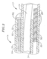
- FIG. 3 is a cross-sectional view of the intermediate section, including the junction between the intermediate section and the mapping assembly.
- FIG. 4 is a schematic perspective view of the mapping assembly according to the invention.
- FIG. 5 is a side view of the mapping assembly according to the invention in a clockwise formation.
- FIG. 6 is a side view of the mapping assembly according to the invention in a counterclockwise formation rotated 90° relative to the assembly depicted in FIG. 5.
- FIG. 7 is a schematic view of the mapping assembly according to the invention.
- FIG. 8 is a schematic view of the mapping assembly according to the invention depicting the relationship between the first and last electrodes.
- FIG. 9 is a schematic view of an alternative mapping assembly according to the invention.
- a catheter having a mapping assembly at its distal end.
- the catheter comprises an elongated catheter body 12 having proximal and distal ends, a intermediate section 14 at the distal end of the catheter body, a control handle 16 at the proximal end of the catheter body, and a mapping assembly 17 mounted at the distal end of the catheter to the intermediate section.
- the catheter body 12 comprises an elongated tubular construction having a single, axial or central lumen 18 .
- the catheter body 12 is flexible, i.e., bendable, but substantially non-compressible along its length.
- the catheter body 12 can be of any suitable construction and made of any suitable material.
- a presently preferred construction comprises an outer wall 20 made of polyurethane or PEBAX.
- the outer wall 20 comprises an imbedded braided mesh of stainless steel or the like to increase torsional stiffness of the catheter body 12 so that, when the control handle 16 is rotated, the intermediate section 14 of the catheter 10 will rotate in a corresponding manner.
- the outer diameter of the catheter body 12 is not critical, but is preferably no more than about 8 french, more preferably 7 french.
- the thickness of the outer wall 20 is not critical, but is thin enough so that the central lumen 18 can accommodate a puller wire, lead wires, and any other desired wires, cables or tubes.
- the inner surface of the outer wall 20 is lined with a stiffening tube (not shown) to provide improved torsional stability.
- a particularly preferred catheter has an outer wall 20 with an outer diameter of from about 0.090 inch to about 0.94 inch and an inner diameter of from about 0.061 inch to about 0.065 inch.
- the intermediate section 14 comprises a short section of tubing 22 having three lumens.
- the first lumen 30 electrode carries lead wires 50
- the second lumen 32 carries a puller wire 64
- the third lumen 34 carries a support member 24 .
- the tubing 22 is made of a suitable non-toxic material that is preferably more flexible than the catheter body 12 .
- a presently preferred material for the tubing 22 is braided polyurethane, i.e., polyurethane with an embedded mesh of braided stainless steel or the like.
- the size of each lumen is not critical, but is sufficient to house the lead wires, puller wire or support member.
- the useful length of the catheter i.e., that portion that can be inserted into the body excluding the mapping assembly 17 , can vary as desired. Preferably the useful length ranges from about 110 cm to about 120 cm.
- the length of the intermediate section 14 is a relatively small portion of the useful length, and preferably ranges from about 3.5 cm to about 10 cm, more preferably6 from about 5 cm to about 6.5 cm.
- FIG. 2 A preferred means for attaching the catheter body 12 to the intermediate section 14 is illustrated in FIG. 2.
- the proximal end of the intermediate section 14 comprises an outer circumferential notch 26 that receives the inner surface of the outer wall 22 of the catheter body 12 .
- the intermediate section 14 and catheter body 12 are attached by glue or the like.
- a spacer (not shown) can be located within the catheter body between the distal end of the stiffening tube (if provided) and the proximal end of the intermediate section.
- the spacer provides a transition in flexibility at the junction of the catheter body and intermediate section, which allows this junction to bend smoothly without folding or kinking.
- a catheter having such a spacer is described in U.S. Pat. No. 5,964,757, the disclosure of which is incorporated herein by reference.
- mapping assembly At the distal end of the intermediate section 14 is a mapping assembly, as shown in FIGS. 3 to 7 .
- the mapping assembly is formed from the distal end of the support member 24 covered by a non-conductive covering 28 .
- the mapping assembly comprises a generally straight proximal region 38 , a generally circular main region and a generally straight distal region 40 .
- the proximal region 38 is mounted on the intermediate section 14 , as described in more detail below, so that its axis is generally parallel to the axis of the intermediate section.
- the proximal region 38 preferably has an exposed length, e.g., not contained within the intermediate section 14 , ranging from about 3 mm to about 12 mm, more preferably about 3 mm to about 8 mm, still more preferably about 5 mm inch, but can vary as desired.
- the generally circular main region 39 does not form a flat circle, but is very slightly helical, as shown in FIGS. 4 to 6 .
- the main region 39 has an outer diameter preferably ranging to about 10 mm to about 25 mm, more preferably about 12 mm to about 20 mm, still more preferably about 15 mm.
- the transition region 41 of the straight proximal region 38 and generally circular main region 39 is slightly curved and formed such that, when viewed from the side with the proximal region at the top of the circular main region as shown in FIG.
- the proximal region (along with the intermediate section 14 ) forms an angle ⁇ with the curved region ranging from about 75° to about 95°, preferably from about 83° to about 93°, more preferably about 87°.
- the main region 39 can curve in a clockwise direction, as shown in FIG. 5, or a counterclockwise direction, as shown in FIG. 6.
- the proximal region (along with the intermediate section 14 ) forms an angle ⁇ with the main region ranging from about 90° to about 135°, preferably from about 100° to about 110°, more preferably about 105°.
- the support member 24 is made of a material having shape-memory, i.e., that can be straightened or bent out of its original shape upon exertion of a force and is capable of substantially returning to its original shape upon removal of the force.
- a particularly preferred material for the support member 24 is a nickel/titanium alloy. Such alloys typically comprise about 55% nickel and 45% titanium, but may comprise from about 54% to about 57% nickel with the balance being titanium.
- a preferred nickel/titanium alloy is Nitinol, which has excellent shape memory, together with ductility, strength, corrosion resistance, electrical resistivity and temperature stability.
- the non-conductive covering 28 can be made of any suitable material, and is preferably made of a biocompatible plastic such as polyurethane or PEBAX
- a series of ring electrodes 36 are mounted on the non-conductive covering 28 of the generally circular main region 39 of the mapping assembly 17 .
- the ring electrodes 36 can be made of any suitable solid conductive material, such as platinum or gold, preferably a combination of platinum and iridium, and mounted onto the non-conductive covering 28 with glue or the like.
- the ring electrodes can be formed by coating the non-conductive covering 28 with an electrically conducting material, like platinum, gold and/or iridium. The coating can be applied using sputtering, ion beam deposition or an equivalent technique.
- each ring electrode 36 is mounted by first forming a hole in the non-conductive covering 28 .
- An electrode lead wire 50 is fed through the hole, and the ring electrode 36 is welded in place over the lead wire and non-conductive covering 28 .
- the lead wires 50 extend between the non-conductive covering 28 and the support member 24 .
- the proximal end of each lead wire 50 is electrically connected to a suitable connector 37 , which is connected to a source of RF energy (not shown).
- the number of ring electrodes 36 on the assembly can vary as desired. Preferably the number of ring electrodes ranges from about six to about twenty, preferably from about eight to about twelve. In a particularly preferred embodiment, the assembly carries ten ring electrodes.
- the ring electrodes 36 are preferably approximately evenly spaced around the generally circular main region 39 , as best shown in FIG. 7. In a particularly preferred embodiment, a distance of approximately 5 mm is provided between the centers of the ring electrodes 36 .
- FIGS. 7 and 8 show a particularly preferred electrode arrangement.
- the generally circular main region 39 is very slightly helical, although FIGS. 7 and 8 depict the main region as a flat circle, as it would generally appear when viewed from the distal end of the catheter.
- the generally straight distal region 40 forms a tangent relative to the generally circular main region 39 and contacts the main region at a tangent point 43 .
- a first electrode 36 a is provided, which is the electrode that is on the generally circular main region 39 closest to the proximal region 38 .
- a second electrode 36 b is provided, which is the electrode that is on the generally circular main region 39 closest to the distal region 40 .
- the first electrode 36 a is positioned along the circumference of the generally circular main region 39 at a distance ⁇ of no more than about 55° from the tangent point, more preferably no more than about 48° from the tangent point, still more preferably from about 15° to about 36° from the tangent point.
- the second electrode 36 b is positioned along the circumference of the generally circular main region 39 at a distance ⁇ of no more than about 55° degrees from the tangent point, more preferably no more than about 48° from the tangent point, still more preferably from about 15° to about 36° from the tangent point.
- the first electrode 36 a is positioned along the circumference of the generally circular main region 39 at a distance ⁇ of no more than 100° from the second electrode 36 b, preferably no more than 80° from the second electrode, still more preferably from about 30° to about 75° from the second electrode.
- the mapping assembly includes a series of ring electrode pairs 35 .
- Each ring electrode pair 35 comprises two closely-spaced ring electrodes 36 .
- the term “ring electrode pair” refers to a pair of ring electrodes that are arranged closer to each other than they are to the other adjacent ring electrodes.
- the distance between two electrodes 36 of an electrode pair 35 is less than about 3 mm, more preferably less than about 2 mm, still more preferably from about 0.5 mm to about 1.5 mm.
- the number of electrode pairs 35 can vary as desired, and preferably ranges from 6 to 14 pairs, more preferably 10 pairs.
- the mapping assembly carries 10 pairs of electrodes with a space of approximately 1 mm between the two electrodes 36 of each pair 35 .
- each ring electrode 36 is relatively short, having a length ranging from about 0.4 mm to about 0.75 mm, with the most distal ring electrode 36 c being longer than the other ring electrodes, preferably having a length ranging from about 1 mm to about 1.5 mm.
- the longer ring electrode provides a signal to the user when the catheter is being viewed under fluoroscopy.
- the mapping assembly is generally circular, it can be difficult for the user to determine which electrodes are placed at a particular location in the heart. By having one ring electrode, such as the most distal ring electrode, sized differently from the other ring electrodes, the user has a reference point when viewing the catheter under fluoroscopy.
- the electrode pairs 35 are preferably approximately evenly spaced around the generally circular main region 39 .
- the closely-spaced electrode pairs 35 allow for more accurate detection of near field pulmonary vein potential versus far field atrial signals, which is very important when trying to treat atrial fibrillation.
- the near field pulmonary vein potentials are very small signals whereas the atria, located very close to the pulmonary vein, provides much larger signals. Accordingly, even when the mapping array is placed in the pulmonary vein, it can be difficult for the physician to determine whether the signal is a small, close potential (from the pulmonary vein) or a larger, farther potential (from the atria).
- Closely-spaced bipoles permit the physician to more accurately determine whether he is looking at a close signal or a far signal. Accordingly, by having closely-spaced electrodes, one is able to target exactly the locations of myocardial tissue that have pulmonary vein potentials and therefore allows the clinician to deliver therapy to the specific tissue. Moreover, the closely-spaced electrodes allow the physician to determine the exact anatomical location of the ostium by the electrical signal.
- additional electrodes could be mounted along the intermediate section 14 , the generally straight proximal section 39 , the transition region 41 , and generally straight distal region 40 .
- the generally straight distal region 40 is provided with an atraumatic design to prevent the distal end of the mapping assembly 17 from penetrating tissue.
- the distal region 40 comprises a tightly wound coil spring 44 made, for example, of stainless steel, such as the mini guidewire commercially available from Cordis Corporation (Miami, Fla.) or a coil having a 0.0045 inch wire size and a 0.009 inch inner diameter, such as that commercially available from Microspring.
- the coil spring 44 is mounted at its proximal end in a short piece of tubing 45 with polyurethane glue or the like, which is then glued or otherwise anchored within the non-conductive covering 28 .
- the tubing 45 is less flexible than the non-conductive covering 28 but more flexible than that support member 24 to provide a transition in flexibility along the length of the mapping assembly 17 .
- the distal end of the distal region 40 is capped, preferably with polyurethane glue 46 , to prevent body fluids from entering the mapping assembly 17 .
- the generally straight distal region 40 has a length of about 0.5 inch, but can be any desired length, for example, ranging from about 0.25 inch to about 1.0 inch.
- the generally straight distal region 40 is preferably sufficiently long to serve as an anchor for introducing the catheter into a guiding sheath, as discussed in more detail below, because the mapping assembly 17 must be straightened upon introduction into the sheath.
- the mapping assembly 17 has a tendency to pull out of the guiding sheath upon its introduction into the guiding sheath. Any other atraumatic tip design that prevents the distal end of the mapping assembly from penetrating tissue could be provided.
- An alternative design in the form of a plastic ball is described in copending patent application Ser. No. 09/370,605, entitled “ATRIAL BRANDING IRON CATHETER AND METHOD FOR TREATING ATRIAL FIBRILLATION”, the entire disclosure of which is incorporated herein by reference.
- the distal region 40 can be formed, at least in part, of a radiopaque material to aid in the positioning of the mapping assembly 17 under fluoroscopy.
- the junction of the intermediate section 14 and mapping assembly 17 is shown in FIG. 3.
- the non-conductive covering 28 is attached to the tubing 22 of the intermediate section by glue or the like.
- the support member 24 extends from the third lumen 32 into the non-conductive covering 28 .
- the proximal end of the support member 24 terminates a short distance within the third lumen 32 , approximately about 5 mm, so as not to adversely affect the ability of the intermediate section 14 to deflect. However, if desired, the proximal end of the support member 24 can extend into the catheter body 12 .
- the lead wires 50 attached to the ring electrodes 36 extend through the first lumen 30 of the intermediate section 14 , through the central lumen 18 of the catheter body 12 , and the control handle 16 , and terminate at their proximal end in the connector 37 .
- the portion of the lead wires 50 extending through the central lumen 18 of the catheter body 12 , control handle 16 and proximal end of the intermediate section 14 are enclosed within a protective sheath 62 , which can be made of any suitable material, preferably polyimide.
- the protective sheath 62 is anchored at its distal end to the proximal end of the intermediate section 14 by gluing it in the first lumen 30 with polyurethane glue or the like.
- the puller wire 64 is provided for deflection of the intermediate section 14 .
- the puller wire 64 extends through the catheter body 12 , is anchored at its proximal end to the control handle 16 , and is anchored at its distal end to the intermediate section 14 .
- the puller wire 64 is made of any suitable metal, such as stainless steel or Nitinol, and is preferably coated with Teflon® or the like. The coating imparts lubricity to the puller wire 64 .
- the puller wire 64 preferably has a diameter ranging from about 0.006 to about 0.010 inch.
- a compression coil 66 is situated within the catheter body 12 in surrounding relation to the puller wire 64 .
- the compression coil 66 extends from the proximal end of the catheter body 12 to the proximal end of the intermediate section 14 .
- the compression coil 66 is made of any suitable metal, preferably stainless steel.
- the compression coil 66 is tightly wound on itself to provide flexibility, i.e., bending, but to resist compression.
- the inner diameter of the compression coil 66 is preferably slightly larger than the diameter of the puller wire 64 .
- the Teflon® coating on the puller wire 64 allows it to slide freely within the compression coil 66 .
- the outer surface of the compression coil 66 is covered by a flexible, non-conductive sheath 68 , e.g., made of polyimide tubing.
- the compression coil 66 is anchored at its proximal end to the outer wall 20 of the catheter body 12 by proximal glue joint 70 and at its distal end to the intermediate section 14 by distal glue joint 72 .
- Both glue joints 70 and 72 preferably comprise polyurethane glue or the like.
- the glue may be applied by means of a syringe or the like through a hole made between the outer surface of the catheter body 12 and the central lumen 18 . Such a hole may be formed, for example, by a needle or the like that punctures the outer wall 20 of the catheter body 12 which is heated sufficiently to form a permanent hole.
- the glue is then introduced through the hole to the outer surface of the compression coil 66 and wicks around the outer circumference to form a glue joint about the entire circumference of the compression coil.
- the puller wire 64 extends into the second lumen 32 of the intermediate section 14 .
- the puller wire 64 is anchored at its distal end to the distal end of the intermediate section 14 , as shown in FIG. 3.
- a T-shaped anchor is formed, which comprises a short piece of tubular stainless steel 80 , e.g., hypodermic stock, which is fitted over the distal end of the puller wire 64 and crimped to fixedly secure it to the puller wire.
- the distal end of the tubular stainless steel 80 is fixedly attached, e.g., by welding, to a cross-piece 82 formed of stainless steel ribbon or the like.
- the cross-piece 82 sits beyond the distal end of the second lumen 32 .
- the cross-piece 82 is larger than the lumen opening and, therefore, cannot be pulled through the opening.
- the distal end of the second lumen 32 is then filled with glue or the like, preferably a polyurethane glue.
- glue or the like preferably a polyurethane glue.
- the puller wire 64 extends through a plastic, preferably Teflon®, puller wire sheath (not shown), which prevents the puller wire 64 from cutting into the wall of the intermediate section 14 when the intermediate section is deflected.
- a suitable guiding sheath is inserted into the patient with its distal end positioned at a desired mapping location.
- An example of a suitable guiding sheath for use in connection with the present invention is the PrefaceTM Braiding Guiding Sheath, commercially available from Cordis Webster (Diamond Bar, Calif.). The distal end of the sheath is guided into one of the atria.
- a catheter in accordance with the present invention is fed through the guiding sheath until its distal end extends out of the distal end of the guiding sheath. As the catheter is fed through the guiding sheath, the mapping assembly 17 is straightened to fit through the sheath.
- mapping assembly 17 is then inserted into a pulmonary vein or other tubular region (such as the coronary sinus, superior vena cava, or inferior vena cava) so that the outer circumference of the generally circular main region 39 of the assembly is in contact with a circumference inside the tubular region.
- a pulmonary vein or other tubular region such as the coronary sinus, superior vena cava, or inferior vena cava
- the outer circumference of the generally circular main region 39 of the assembly is in contact with a circumference inside the tubular region.
- at least about 50%, more preferably at least about 70%, and still more preferably at least about 80% of the circumference of the generally circular main region is in contact with a circumference inside the tubular region.
- the circular arrangement of the electrodes 36 permits measurement of the electrical activity at that circumference of the tubular structure so that ectopic beats between the electrodes can be identified.
- the size of the generally circular main region 39 permits measurement of electrical activity along a diameter of a pulmonary vein or other tubular structure of or near the heart because the circular main region has a diameter generally corresponding to that of a pulmonary vein or the coronary sinus. Additionally, because the main region 39 preferably does not form a flat circle, but instead is somewhat helical, as shown in FIG. 4, it is easier for the user to guide the mapping assembly 17 into a tubular region.
- two or more puller wires can be provided to enhance the ability to manipulate the intermediate section.
- a second puller wire and a surrounding second compression coil extend through the catheter body and into an additional off-axis lumen in the intermediate section.
- the first puller wire is preferably anchored proximal to the anchor location of the second puller wire.
- suitable designs of catheters having two or more puller wires, including suitable control handles for such embodiments, are described, for example, in U.S. patent application Ser. Nos. 08/924,611, filed Sep. 5, 1997; 09/130,359, filed Aug. 7, 1998; 09/143,426, filed Aug. 28, 1998; and 09/157,055, filed Sep. 18, 1998, the disclosures of which are incorporated herein by reference.
Abstract
A method is provided for mapping electrical activity within a tubular region of or near the heart having a inner circumference, such as a pulmonary vein. The method comprises inserting into the heart a distal end of a mapping catheter. The mapping catheter comprises an elongated tubular catheter body having an outer wall, proximal and distal ends, and at least one lumen extending therethrough. The catheter includes a mapping assembly comprising a tubular structure comprising a pre-formed generally circular main region generally transverse and distal to the catheter body and having an outer circumference. The tubular structure comprises a non-conductive cover over at least the main region of the mapping assembly. A plurality of electrode pairs, each comprising two ring electrodes, are carried by the generally circular main region of the mapping assembly. The method further comprises contacting the outer circumference of the generally circular main region with the inner circumference of the tubular region and mapping the electrical activity within the tubular region with the electrodes along the generally circular main region.
Description
- This application is a divisional of U.S. application Ser. No. 09/943,546, filed Aug. 30, 2001, which is a continuation-in-part of U.S. application Ser. No. 09/551,467, filed Apr. 17, 2000,which claims the benefit of U.S. Provisional Application No. 60/178,478, filed Jan. 27, 2000, the entire disclosures of which are incorporated herein by reference.
- The present invention relates to a method for mapping a tubular region of or near the heart, and more particularly, a method for mapping the pulmonary vein.
- Atrial fibrillation is a common sustained cardiac arrhythmia and a major cause of stroke. This condition is perpetuated by reentrant wavelets propagating in an abnormal atrial-tissue substrate. Various approaches have been developed to interrupt wavelets, including surgical or catheter-mediated atriotomy. Prior to treating the condition, one has to first determine the location of the wavelets. Various techniques have been proposed for making such a determination. None of the proposed techniques, however, provide for measurement of the activity within a pulmonary vein, coronary sinus or other tubular structure about the inner circumference of the structure.
- A method is provided for mapping electrical activity within a tubular region of or near the heart having an inner circumference, such as a pulmonary vein. The method comprises inserting into the heart a distal end of a mapping catheter. The mapping catheter comprises an elongated tubular catheter body having an outer wall, proximal and distal ends, and at least one lumen extending therethrough. The catheter includes a mapping assembly comprising a tubular structure comprising a pre-formed generally circular main region generally transverse and distal to the catheter body and having an outer circumference. The tubular structure comprises a non-conductive cover over at least the main region of the mapping assembly. A plurality of electrode pairs, each comprising two ring electrodes, are carried by the generally circular main region of the mapping assembly. The method further comprises contacting the outer circumference of the generally circular main region with the inner circumference of the tubular region and mapping the electrical activity within the tubular region with the electrodes along the generally circular main region.
- These and other features and advantages of the present invention will be better understood by reference to the following detailed description when considered in conjunction with the accompanying drawings wherein:
- FIG. 1 is a side cross-sectional view of an embodiment of the catheter of the invention.
- FIG. 2 is a side cross-sectional view of a catheter body according to the invention, including the junction between the catheter body and intermediate section.
- FIG. 3 is a cross-sectional view of the intermediate section, including the junction between the intermediate section and the mapping assembly.
- FIG. 4 is a schematic perspective view of the mapping assembly according to the invention.
- FIG. 5 is a side view of the mapping assembly according to the invention in a clockwise formation.
- FIG. 6 is a side view of the mapping assembly according to the invention in a counterclockwise formation rotated 90° relative to the assembly depicted in FIG. 5.
- FIG. 7 is a schematic view of the mapping assembly according to the invention.
- FIG. 8 is a schematic view of the mapping assembly according to the invention depicting the relationship between the first and last electrodes.
- FIG. 9 is a schematic view of an alternative mapping assembly according to the invention.
- In a particularly preferred embodiment of the invention, there is provided a catheter having a mapping assembly at its distal end. As shown in FIG. 1, the catheter comprises an
elongated catheter body 12 having proximal and distal ends, aintermediate section 14 at the distal end of the catheter body, acontrol handle 16 at the proximal end of the catheter body, and amapping assembly 17 mounted at the distal end of the catheter to the intermediate section. - With reference to FIG. 2, the
catheter body 12 comprises an elongated tubular construction having a single, axial orcentral lumen 18. Thecatheter body 12 is flexible, i.e., bendable, but substantially non-compressible along its length. Thecatheter body 12 can be of any suitable construction and made of any suitable material. A presently preferred construction comprises anouter wall 20 made of polyurethane or PEBAX. Theouter wall 20 comprises an imbedded braided mesh of stainless steel or the like to increase torsional stiffness of thecatheter body 12 so that, when thecontrol handle 16 is rotated, theintermediate section 14 of the catheter 10 will rotate in a corresponding manner. - The outer diameter of the
catheter body 12 is not critical, but is preferably no more than about 8 french, more preferably 7 french. Likewise the thickness of theouter wall 20 is not critical, but is thin enough so that thecentral lumen 18 can accommodate a puller wire, lead wires, and any other desired wires, cables or tubes. If desired, the inner surface of theouter wall 20 is lined with a stiffening tube (not shown) to provide improved torsional stability. A particularly preferred catheter has anouter wall 20 with an outer diameter of from about 0.090 inch to about 0.94 inch and an inner diameter of from about 0.061 inch to about 0.065 inch. - The
intermediate section 14 comprises a short section oftubing 22 having three lumens. Thefirst lumen 30 electrode carrieslead wires 50, thesecond lumen 32 carries apuller wire 64, and thethird lumen 34 carries asupport member 24. Thetubing 22 is made of a suitable non-toxic material that is preferably more flexible than thecatheter body 12. A presently preferred material for thetubing 22 is braided polyurethane, i.e., polyurethane with an embedded mesh of braided stainless steel or the like. The size of each lumen is not critical, but is sufficient to house the lead wires, puller wire or support member. - The useful length of the catheter, i.e., that portion that can be inserted into the body excluding the
mapping assembly 17, can vary as desired. Preferably the useful length ranges from about 110 cm to about 120 cm. The length of theintermediate section 14 is a relatively small portion of the useful length, and preferably ranges from about 3.5 cm to about 10 cm, more preferably6 from about 5 cm to about 6.5 cm. - A preferred means for attaching the
catheter body 12 to theintermediate section 14 is illustrated in FIG. 2. The proximal end of theintermediate section 14 comprises an outercircumferential notch 26 that receives the inner surface of theouter wall 22 of thecatheter body 12. Theintermediate section 14 andcatheter body 12 are attached by glue or the like. - If desired, a spacer (not shown) can be located within the catheter body between the distal end of the stiffening tube (if provided) and the proximal end of the intermediate section. The spacer provides a transition in flexibility at the junction of the catheter body and intermediate section, which allows this junction to bend smoothly without folding or kinking. A catheter having such a spacer is described in U.S. Pat. No. 5,964,757, the disclosure of which is incorporated herein by reference.
- At the distal end of the
intermediate section 14 is a mapping assembly, as shown in FIGS. 3 to 7. The mapping assembly is formed from the distal end of thesupport member 24 covered by a non-conductive covering 28. The mapping assembly comprises a generally straightproximal region 38, a generally circular main region and a generally straightdistal region 40. Theproximal region 38 is mounted on theintermediate section 14, as described in more detail below, so that its axis is generally parallel to the axis of the intermediate section. Theproximal region 38 preferably has an exposed length, e.g., not contained within theintermediate section 14, ranging from about 3 mm to about 12 mm, more preferably about 3 mm to about 8 mm, still more preferably about 5 mm inch, but can vary as desired. - The generally circular
main region 39 does not form a flat circle, but is very slightly helical, as shown in FIGS. 4 to 6. Themain region 39 has an outer diameter preferably ranging to about 10 mm to about 25 mm, more preferably about 12 mm to about 20 mm, still more preferably about 15 mm. Thetransition region 41 of the straightproximal region 38 and generally circularmain region 39 is slightly curved and formed such that, when viewed from the side with the proximal region at the top of the circular main region as shown in FIG. 5, the proximal region (along with the intermediate section 14) forms an angle α with the curved region ranging from about 75° to about 95°, preferably from about 83° to about 93°, more preferably about 87°. Themain region 39 can curve in a clockwise direction, as shown in FIG. 5, or a counterclockwise direction, as shown in FIG. 6. When theassembly 17 is turned 90°, as shown in FIG. 6, so that thetransition region 41 is near the center of the main region, the proximal region (along with the intermediate section 14) forms an angle β with the main region ranging from about 90° to about 135°, preferably from about 100° to about 110°, more preferably about 105°. - The
support member 24 is made of a material having shape-memory, i.e., that can be straightened or bent out of its original shape upon exertion of a force and is capable of substantially returning to its original shape upon removal of the force. A particularly preferred material for thesupport member 24 is a nickel/titanium alloy. Such alloys typically comprise about 55% nickel and 45% titanium, but may comprise from about 54% to about 57% nickel with the balance being titanium. A preferred nickel/titanium alloy is Nitinol, which has excellent shape memory, together with ductility, strength, corrosion resistance, electrical resistivity and temperature stability. Thenon-conductive covering 28 can be made of any suitable material, and is preferably made of a biocompatible plastic such as polyurethane or PEBAX - A series of
ring electrodes 36 are mounted on the non-conductive covering 28 of the generally circularmain region 39 of themapping assembly 17. Thering electrodes 36 can be made of any suitable solid conductive material, such as platinum or gold, preferably a combination of platinum and iridium, and mounted onto the non-conductive covering 28 with glue or the like. Alternatively, the ring electrodes can be formed by coating the non-conductive covering 28 with an electrically conducting material, like platinum, gold and/or iridium. The coating can be applied using sputtering, ion beam deposition or an equivalent technique. - In a preferred embodiment, each
ring electrode 36 is mounted by first forming a hole in thenon-conductive covering 28. Anelectrode lead wire 50 is fed through the hole, and thering electrode 36 is welded in place over the lead wire andnon-conductive covering 28. Thelead wires 50 extend between thenon-conductive covering 28 and thesupport member 24. The proximal end of eachlead wire 50 is electrically connected to asuitable connector 37, which is connected to a source of RF energy (not shown). - The number of
ring electrodes 36 on the assembly can vary as desired. Preferably the number of ring electrodes ranges from about six to about twenty, preferably from about eight to about twelve. In a particularly preferred embodiment, the assembly carries ten ring electrodes. Thering electrodes 36 are preferably approximately evenly spaced around the generally circularmain region 39, as best shown in FIG. 7. In a particularly preferred embodiment, a distance of approximately 5 mm is provided between the centers of thering electrodes 36. - FIGS. 7 and 8 show a particularly preferred electrode arrangement. As explained above, the generally circular
main region 39 is very slightly helical, although FIGS. 7 and 8 depict the main region as a flat circle, as it would generally appear when viewed from the distal end of the catheter. The generally straightdistal region 40 forms a tangent relative to the generally circularmain region 39 and contacts the main region at a tangent point 43. Afirst electrode 36 a is provided, which is the electrode that is on the generally circularmain region 39 closest to theproximal region 38. Asecond electrode 36 b is provided, which is the electrode that is on the generally circularmain region 39 closest to thedistal region 40. Preferably, thefirst electrode 36 a is positioned along the circumference of the generally circularmain region 39 at a distance θ of no more than about 55° from the tangent point, more preferably no more than about 48° from the tangent point, still more preferably from about 15° to about 36° from the tangent point. Preferably thesecond electrode 36 b is positioned along the circumference of the generally circularmain region 39 at a distance ω of no more than about 55° degrees from the tangent point, more preferably no more than about 48° from the tangent point, still more preferably from about 15° to about 36° from the tangent point. Preferably thefirst electrode 36 a is positioned along the circumference of the generally circularmain region 39 at a distance γ of no more than 100° from thesecond electrode 36 b, preferably no more than 80° from the second electrode, still more preferably from about 30° to about 75° from the second electrode. - An alternative electrode arrangement is depicted in FIG. 9. In this embodiment, the mapping assembly includes a series of ring electrode pairs 35. Each
ring electrode pair 35 comprises two closely-spacedring electrodes 36. As used herein, the term “ring electrode pair” refers to a pair of ring electrodes that are arranged closer to each other than they are to the other adjacent ring electrodes. Preferably the distance between twoelectrodes 36 of anelectrode pair 35 is less than about 3 mm, more preferably less than about 2 mm, still more preferably from about 0.5 mm to about 1.5 mm. The number of electrode pairs 35 can vary as desired, and preferably ranges from 6 to 14 pairs, more preferably 10 pairs. - In a particularly preferred embodiment, the mapping assembly carries 10 pairs of electrodes with a space of approximately 1 mm between the two
electrodes 36 of eachpair 35. Preferably eachring electrode 36 is relatively short, having a length ranging from about 0.4 mm to about 0.75 mm, with the mostdistal ring electrode 36 c being longer than the other ring electrodes, preferably having a length ranging from about 1 mm to about 1.5 mm. The longer ring electrode provides a signal to the user when the catheter is being viewed under fluoroscopy. Specifically, because the mapping assembly is generally circular, it can be difficult for the user to determine which electrodes are placed at a particular location in the heart. By having one ring electrode, such as the most distal ring electrode, sized differently from the other ring electrodes, the user has a reference point when viewing the catheter under fluoroscopy. - Regardless of the size and number of the
ring electrodes 36, the electrode pairs 35 are preferably approximately evenly spaced around the generally circularmain region 39. The closely-spaced electrode pairs 35 allow for more accurate detection of near field pulmonary vein potential versus far field atrial signals, which is very important when trying to treat atrial fibrillation. Specifically, the near field pulmonary vein potentials are very small signals whereas the atria, located very close to the pulmonary vein, provides much larger signals. Accordingly, even when the mapping array is placed in the pulmonary vein, it can be difficult for the physician to determine whether the signal is a small, close potential (from the pulmonary vein) or a larger, farther potential (from the atria). Closely-spaced bipoles permit the physician to more accurately determine whether he is looking at a close signal or a far signal. Accordingly, by having closely-spaced electrodes, one is able to target exactly the locations of myocardial tissue that have pulmonary vein potentials and therefore allows the clinician to deliver therapy to the specific tissue. Moreover, the closely-spaced electrodes allow the physician to determine the exact anatomical location of the ostium by the electrical signal. - If desired, additional electrodes (not shown) could be mounted along the
intermediate section 14, the generally straightproximal section 39, thetransition region 41, and generally straightdistal region 40. - The generally straight
distal region 40 is provided with an atraumatic design to prevent the distal end of themapping assembly 17 from penetrating tissue. In the depicted embodiment, thedistal region 40 comprises a tightly woundcoil spring 44 made, for example, of stainless steel, such as the mini guidewire commercially available from Cordis Corporation (Miami, Fla.) or a coil having a 0.0045 inch wire size and a 0.009 inch inner diameter, such as that commercially available from Microspring. Thecoil spring 44 is mounted at its proximal end in a short piece oftubing 45 with polyurethane glue or the like, which is then glued or otherwise anchored within thenon-conductive covering 28. Thetubing 45 is less flexible than the non-conductive covering 28 but more flexible than thatsupport member 24 to provide a transition in flexibility along the length of themapping assembly 17. The distal end of thedistal region 40 is capped, preferably withpolyurethane glue 46, to prevent body fluids from entering themapping assembly 17. In the depicted embodiment, the generally straightdistal region 40 has a length of about 0.5 inch, but can be any desired length, for example, ranging from about 0.25 inch to about 1.0 inch. The generally straightdistal region 40 is preferably sufficiently long to serve as an anchor for introducing the catheter into a guiding sheath, as discussed in more detail below, because themapping assembly 17 must be straightened upon introduction into the sheath. Without having the generally straightdistal region 40 as an anchor, themapping assembly 17 has a tendency to pull out of the guiding sheath upon its introduction into the guiding sheath. Any other atraumatic tip design that prevents the distal end of the mapping assembly from penetrating tissue could be provided. An alternative design in the form of a plastic ball is described in copending patent application Ser. No. 09/370,605, entitled “ATRIAL BRANDING IRON CATHETER AND METHOD FOR TREATING ATRIAL FIBRILLATION”, the entire disclosure of which is incorporated herein by reference. Additionally, if desired, thedistal region 40 can be formed, at least in part, of a radiopaque material to aid in the positioning of themapping assembly 17 under fluoroscopy. - The junction of the
intermediate section 14 andmapping assembly 17 is shown in FIG. 3. Thenon-conductive covering 28 is attached to thetubing 22 of the intermediate section by glue or the like. Thesupport member 24 extends from thethird lumen 32 into thenon-conductive covering 28. The proximal end of thesupport member 24 terminates a short distance within thethird lumen 32, approximately about 5 mm, so as not to adversely affect the ability of theintermediate section 14 to deflect. However, if desired, the proximal end of thesupport member 24 can extend into thecatheter body 12. - The
lead wires 50 attached to thering electrodes 36 extend through thefirst lumen 30 of theintermediate section 14, through thecentral lumen 18 of thecatheter body 12, and the control handle 16, and terminate at their proximal end in theconnector 37. The portion of thelead wires 50 extending through thecentral lumen 18 of thecatheter body 12, control handle 16 and proximal end of theintermediate section 14 are enclosed within aprotective sheath 62, which can be made of any suitable material, preferably polyimide. Theprotective sheath 62 is anchored at its distal end to the proximal end of theintermediate section 14 by gluing it in thefirst lumen 30 with polyurethane glue or the like. - The
puller wire 64 is provided for deflection of theintermediate section 14. Thepuller wire 64 extends through thecatheter body 12, is anchored at its proximal end to the control handle 16, and is anchored at its distal end to theintermediate section 14. Thepuller wire 64 is made of any suitable metal, such as stainless steel or Nitinol, and is preferably coated with Teflon® or the like. The coating imparts lubricity to thepuller wire 64. Thepuller wire 64 preferably has a diameter ranging from about 0.006 to about 0.010 inch. - A
compression coil 66 is situated within thecatheter body 12 in surrounding relation to thepuller wire 64. Thecompression coil 66 extends from the proximal end of thecatheter body 12 to the proximal end of theintermediate section 14. Thecompression coil 66 is made of any suitable metal, preferably stainless steel. Thecompression coil 66 is tightly wound on itself to provide flexibility, i.e., bending, but to resist compression. The inner diameter of thecompression coil 66 is preferably slightly larger than the diameter of thepuller wire 64. The Teflon® coating on thepuller wire 64 allows it to slide freely within thecompression coil 66. The outer surface of thecompression coil 66 is covered by a flexible,non-conductive sheath 68, e.g., made of polyimide tubing. - The
compression coil 66 is anchored at its proximal end to theouter wall 20 of thecatheter body 12 by proximal glue joint 70 and at its distal end to theintermediate section 14 by distal glue joint 72. Bothglue joints catheter body 12 and thecentral lumen 18. Such a hole may be formed, for example, by a needle or the like that punctures theouter wall 20 of thecatheter body 12 which is heated sufficiently to form a permanent hole. The glue is then introduced through the hole to the outer surface of thecompression coil 66 and wicks around the outer circumference to form a glue joint about the entire circumference of the compression coil. - The
puller wire 64 extends into thesecond lumen 32 of theintermediate section 14. Preferably thepuller wire 64 is anchored at its distal end to the distal end of theintermediate section 14, as shown in FIG. 3. Specifically, a T-shaped anchor is formed, which comprises a short piece of tubularstainless steel 80, e.g., hypodermic stock, which is fitted over the distal end of thepuller wire 64 and crimped to fixedly secure it to the puller wire. The distal end of the tubularstainless steel 80 is fixedly attached, e.g., by welding, to across-piece 82 formed of stainless steel ribbon or the like. Thecross-piece 82 sits beyond the distal end of thesecond lumen 32. Thecross-piece 82 is larger than the lumen opening and, therefore, cannot be pulled through the opening. The distal end of thesecond lumen 32 is then filled with glue or the like, preferably a polyurethane glue. Within thesecond lumen 32 of theintermediate section 14, thepuller wire 64 extends through a plastic, preferably Teflon®, puller wire sheath (not shown), which prevents thepuller wire 64 from cutting into the wall of theintermediate section 14 when the intermediate section is deflected. - Longitudinal movement of the puller wire 42 relative to the
catheter body 12, which results in deflection of theintermediate section 14, is accomplished by suitable manipulation of the control handle 16. Examples of suitable control handles for use in the present invention are disclosed, for example, in U.S. Pat. Nos. Re 34,502 and 5,897,529, the entire disclosures of which are incorporated herein by reference. - In use, a suitable guiding sheath is inserted into the patient with its distal end positioned at a desired mapping location. An example of a suitable guiding sheath for use in connection with the present invention is the Preface™ Braiding Guiding Sheath, commercially available from Cordis Webster (Diamond Bar, Calif.). The distal end of the sheath is guided into one of the atria. A catheter in accordance with the present invention is fed through the guiding sheath until its distal end extends out of the distal end of the guiding sheath. As the catheter is fed through the guiding sheath, the
mapping assembly 17 is straightened to fit through the sheath. Once the distal end of the catheter is positioned at the desired mapping location, the guiding sheath is pulled proximally, allowing the deflectableintermediate section 14 andmapping assembly 17 to extend outside the sheath, and themapping assembly 17 returns to its original shape due to the shape-memory of thesupport member 24. Themapping assembly 17 is then inserted into a pulmonary vein or other tubular region (such as the coronary sinus, superior vena cava, or inferior vena cava) so that the outer circumference of the generally circularmain region 39 of the assembly is in contact with a circumference inside the tubular region. Preferably at least about 50%, more preferably at least about 70%, and still more preferably at least about 80% of the circumference of the generally circular main region is in contact with a circumference inside the tubular region. - The circular arrangement of the
electrodes 36 permits measurement of the electrical activity at that circumference of the tubular structure so that ectopic beats between the electrodes can be identified. The size of the generally circularmain region 39 permits measurement of electrical activity along a diameter of a pulmonary vein or other tubular structure of or near the heart because the circular main region has a diameter generally corresponding to that of a pulmonary vein or the coronary sinus. Additionally, because themain region 39 preferably does not form a flat circle, but instead is somewhat helical, as shown in FIG. 4, it is easier for the user to guide themapping assembly 17 into a tubular region. - If desired, two or more puller wires can be provided to enhance the ability to manipulate the intermediate section. In such an embodiment, a second puller wire and a surrounding second compression coil extend through the catheter body and into an additional off-axis lumen in the intermediate section. The first puller wire is preferably anchored proximal to the anchor location of the second puller wire. Suitable designs of catheters having two or more puller wires, including suitable control handles for such embodiments, are described, for example, in U.S. patent application Ser. Nos. 08/924,611, filed Sep. 5, 1997; 09/130,359, filed Aug. 7, 1998; 09/143,426, filed Aug. 28, 1998; and 09/157,055, filed Sep. 18, 1998, the disclosures of which are incorporated herein by reference.
- The preceding description has been presented with reference to presently preferred embodiments of the invention. Workers skilled in the art and technology to which this invention pertains will appreciate that alterations and changes in the described structure may be practiced without meaningfully departing from the principal, spirit and scope of this invention.
- Accordingly, the foregoing description should not be read as pertaining only to the precise structures described and illustrated in the accompanying drawings, but rather should be read consistent with and as support to the following claims which are to have their fullest and fair scope.
Claims (26)
1. A method for mapping electrical activity within a tubular region of or near the heart having a inner circumference, the method comprising:
inserting into the heart a distal end of a mapping catheter comprising:
an elongated tubular catheter body having an outer wall, proximal and distal ends, and at least one lumen extending therethrough, and
a mapping assembly comprising:
a tubular structure comprising a pre-formed generally circular main region generally transverse and distal to the catheter body and having an outer circumference, wherein the tubular structure comprises a non-conductive cover over at least the main region of the mapping assembly, and
a plurality of electrode pairs, each comprising two ring electrodes, carried by the generally circular main region of the mapping assembly;
contacting the outer circumference of the generally circular main region with the inner circumference of the tubular region; and
mapping the electrical activity within the tubular region with the electrodes along the generally circular main region.
2. The method according to claim 1 , wherein the mapping assembly further comprises a support member having shape-memory disposed within at least the main region of the mapping assembly.
3. The method according to claim 1 , wherein the mapping assembly further comprises a generally straight distal region distal to the main region, the generally straight distal region having an atraumatic design to prevent the distal end of the mapping assembly from penetrating tissue.
4. The method according to claim 1 , wherein the mapping assembly further comprises a generally straight proximal region attached to the catheter body and a transition region connecting the proximal region and the main region.
5. The method according to claim 1 , wherein the generally circular main region has an outer diameter ranging to about 10 mm to about 25 mm.
6. The method according to claim 1 , wherein the generally circular main region has an outer diameter ranging to about 12 mm to about 20 mm.
7. The method according to claim 1 , wherein the number of ring electrode pairs along the generally circular main region ranges from about six to about fourteen.
8. The method according to claim 1 , comprising ten ring electrode pairs along the generally circular main region.
9. The method according to claim 1 , wherein the ring electrode pairs are approximately evenly spaced around the generally circular main region.
10. The method according to claim 1 , wherein the distance between two ring electrodes of each ring electrode pair is less than about 3 mm.
11. The method according to claim 1 , wherein the distance between two ring electrodes of each ring electrode pair is less than about 2 mm.
12. The method according to claim 1 , wherein the distance between two ring electrodes of each ring electrode pair ranges from about 0.5 mm to about 1.5 mm.
13. The method according to claim 1 , wherein at least some of the ring electrodes of the electrode pairs have a length ranging from about 0.4 mm to about 0.75 mm.
14. The method according to claim 1 , wherein one ring electrode has a length longer than the length of the other ring electrodes.
15. The method according to claim 1 , wherein one ring electrode has a length ranging from about 1 mm to about 1.5 mm and all of the other ring electrodes each having a length ranging from about 0.4 mm to about 0.75 mm.
16. The method according to claim 1 , wherein the tubular region is selected from the group consisting of pulmonary veins, the coronary sinus, the superior vena cava, and the inferior vena cava.
17. The method according to claim 1 , wherein the tubular region is a pulmonary vein.
18. The method according to claim 1 , wherein the generally circular main region has an outer diameter ranging to about 12 mm to about 20 mm.
19. The method according to claim 1 , wherein at least about 50% of the outer circumference of the generally circular main region is in contact with the inner circumference of the tubular region.
20. The method according to claim 1 , wherein at least about 80% of the outer circumference of the generally circular main region is in contact with the inner circumference of the tubular region.
21. A method for mapping electrical activity within a pulmonary vein of a patient, the method comprising:
inserting into the patient a mapping catheter comprising:
an elongated tubular catheter body having an outer wall, proximal and distal ends, and at least one lumen extending therethrough, and
a mapping assembly comprising:
a tubular structure comprising a pre-formed generally circular main region generally transverse and distal to the catheter body and having an outer circumference, wherein the tubular structure comprises a non-conductive cover over at least the main region of the mapping assembly, and
a plurality of electrode pairs, each comprising two ring electrodes, carried by the generally circular main region of the mapping assembly;
contacting outer circumference of the generally circular main region with the inner circumference of the pulmonary vein; and
mapping the electrical activity within the pulmonary with the electrodes along the generally circular main region.
22. The method according to claim 21 , wherein the distance between two ring electrodes of each ring electrode pair is less than about 2 mm.
23. The method according to claim 21 , wherein the distance between two ring electrodes of each ring electrode pair ranges from about 0.5 mm to about 1.5 mm.
24. The method according to claim 21 , wherein at least some of the ring electrodes of the electrode pairs have a length ranging from about 0.4 mm to about 0.75 mm.
25. The method according to claim 21 , wherein one ring electrode has a length longer than the length of the other ring electrodes.
26. The method according to claim 21 , wherein one ring electrode has a length ranging from about 1 mm to about 1.5 mm and all of the other ring electrodes each having a length ranging from about 0.4 mm to about 0.75 mm.
Priority Applications (2)
| Application Number | Priority Date | Filing Date | Title |
|---|---|---|---|
| US10/407,772 US7181262B2 (en) | 2000-01-27 | 2003-04-04 | Method for mapping a tubular region near the heart |
| US11/706,601 US7610073B2 (en) | 2000-01-27 | 2007-02-13 | Method for mapping a tubular region near the heart |
Applications Claiming Priority (4)
| Application Number | Priority Date | Filing Date | Title |
|---|---|---|---|
| US17847800P | 2000-01-27 | 2000-01-27 | |
| US09/551,467 US6628976B1 (en) | 2000-01-27 | 2000-04-17 | Catheter having mapping assembly |
| US09/943,546 US6711428B2 (en) | 2000-01-27 | 2001-08-30 | Catheter having mapping assembly |
| US10/407,772 US7181262B2 (en) | 2000-01-27 | 2003-04-04 | Method for mapping a tubular region near the heart |
Related Parent Applications (1)
| Application Number | Title | Priority Date | Filing Date |
|---|---|---|---|
| US09/943,546 Division US6711428B2 (en) | 2000-01-27 | 2001-08-30 | Catheter having mapping assembly |
Related Child Applications (1)
| Application Number | Title | Priority Date | Filing Date |
|---|---|---|---|
| US11/706,601 Continuation US7610073B2 (en) | 2000-01-27 | 2007-02-13 | Method for mapping a tubular region near the heart |
Publications (2)
| Publication Number | Publication Date |
|---|---|
| US20030191380A1 true US20030191380A1 (en) | 2003-10-09 |
| US7181262B2 US7181262B2 (en) | 2007-02-20 |
Family
ID=25479843
Family Applications (4)
| Application Number | Title | Priority Date | Filing Date |
|---|---|---|---|
| US09/943,546 Expired - Lifetime US6711428B2 (en) | 2000-01-27 | 2001-08-30 | Catheter having mapping assembly |
| US10/407,772 Expired - Lifetime US7181262B2 (en) | 2000-01-27 | 2003-04-04 | Method for mapping a tubular region near the heart |
| US10/443,404 Expired - Lifetime US6987996B2 (en) | 2000-01-27 | 2003-05-22 | Catheter having mapping assembly |
| US11/706,601 Expired - Fee Related US7610073B2 (en) | 2000-01-27 | 2007-02-13 | Method for mapping a tubular region near the heart |
Family Applications Before (1)
| Application Number | Title | Priority Date | Filing Date |
|---|---|---|---|
| US09/943,546 Expired - Lifetime US6711428B2 (en) | 2000-01-27 | 2001-08-30 | Catheter having mapping assembly |
Family Applications After (2)
| Application Number | Title | Priority Date | Filing Date |
|---|---|---|---|
| US10/443,404 Expired - Lifetime US6987996B2 (en) | 2000-01-27 | 2003-05-22 | Catheter having mapping assembly |
| US11/706,601 Expired - Fee Related US7610073B2 (en) | 2000-01-27 | 2007-02-13 | Method for mapping a tubular region near the heart |
Country Status (6)
| Country | Link |
|---|---|
| US (4) | US6711428B2 (en) |
| EP (1) | EP1287782B1 (en) |
| JP (1) | JP4350346B2 (en) |
| AT (1) | ATE404112T1 (en) |
| CA (1) | CA2399919C (en) |
| DE (1) | DE60228174D1 (en) |
Cited By (6)
| Publication number | Priority date | Publication date | Assignee | Title |
|---|---|---|---|---|
| US20040143175A1 (en) * | 2000-01-27 | 2004-07-22 | Biosense Webster, Inc. | Bidirectional catheter having mapping assembly |
| US20040158140A1 (en) * | 2000-01-27 | 2004-08-12 | Biosense Webster, Inc. | Catheter having mapping assembly |
| US20070038055A1 (en) * | 2000-01-27 | 2007-02-15 | Biosense Webster, Inc. | Catheter having mapping assembly |
| US20070179375A1 (en) * | 2000-01-27 | 2007-08-02 | Biosense Webster, Inc. | Method for mapping a tubular region near the heart |
| US11589768B2 (en) | 2014-10-13 | 2023-02-28 | Boston Scientific Scimed Inc. | Tissue diagnosis and treatment using mini-electrodes |
| US11684416B2 (en) | 2009-02-11 | 2023-06-27 | Boston Scientific Scimed, Inc. | Insulated ablation catheter devices and methods of use |
Families Citing this family (76)
| Publication number | Priority date | Publication date | Assignee | Title |
|---|---|---|---|---|
| US6878147B2 (en) | 2001-11-02 | 2005-04-12 | Vivant Medical, Inc. | High-strength microwave antenna assemblies |
| US7128739B2 (en) | 2001-11-02 | 2006-10-31 | Vivant Medical, Inc. | High-strength microwave antenna assemblies and methods of use |
| US7311705B2 (en) * | 2002-02-05 | 2007-12-25 | Medtronic, Inc. | Catheter apparatus for treatment of heart arrhythmia |
| US7142903B2 (en) | 2003-03-12 | 2006-11-28 | Biosense Webster, Inc. | Catheter with contractable mapping assembly |
| US7344543B2 (en) * | 2003-07-01 | 2008-03-18 | Medtronic, Inc. | Method and apparatus for epicardial left atrial appendage isolation in patients with atrial fibrillation |
| US7311703B2 (en) | 2003-07-18 | 2007-12-25 | Vivant Medical, Inc. | Devices and methods for cooling microwave antennas |
| US6973339B2 (en) * | 2003-07-29 | 2005-12-06 | Biosense, Inc | Lasso for pulmonary vein mapping and ablation |
| US20060089637A1 (en) * | 2004-10-14 | 2006-04-27 | Werneth Randell L | Ablation catheter |
| US8617152B2 (en) * | 2004-11-15 | 2013-12-31 | Medtronic Ablation Frontiers Llc | Ablation system with feedback |
| US7468062B2 (en) | 2004-11-24 | 2008-12-23 | Ablation Frontiers, Inc. | Atrial ablation catheter adapted for treatment of septal wall arrhythmogenic foci and method of use |
| US7429261B2 (en) * | 2004-11-24 | 2008-09-30 | Ablation Frontiers, Inc. | Atrial ablation catheter and method of use |
| US7799019B2 (en) * | 2005-05-10 | 2010-09-21 | Vivant Medical, Inc. | Reinforced high strength microwave antenna |
| JP2009500052A (en) * | 2005-06-20 | 2009-01-08 | アブレーション フロンティアズ,インコーポレーテッド | Ablation catheter |
| WO2007008954A2 (en) | 2005-07-11 | 2007-01-18 | Ablation Frontiers | Low power tissue ablation system |
| US8657814B2 (en) | 2005-08-22 | 2014-02-25 | Medtronic Ablation Frontiers Llc | User interface for tissue ablation system |
| US8784336B2 (en) | 2005-08-24 | 2014-07-22 | C. R. Bard, Inc. | Stylet apparatuses and methods of manufacture |
| US8172758B2 (en) | 2006-03-06 | 2012-05-08 | Imacor Inc. | Transesophageal ultrasound probe with an adaptive bending section |
| US20070270679A1 (en) * | 2006-05-17 | 2007-11-22 | Duy Nguyen | Deflectable variable radius catheters |
| US7774039B2 (en) * | 2006-09-05 | 2010-08-10 | Boston Scientific Scimed, Inc. | Multi-bend steerable mapping catheter |
| US8068920B2 (en) | 2006-10-03 | 2011-11-29 | Vincent A Gaudiani | Transcoronary sinus pacing system, LV summit pacing, early mitral closure pacing, and methods therefor |
| US7794407B2 (en) | 2006-10-23 | 2010-09-14 | Bard Access Systems, Inc. | Method of locating the tip of a central venous catheter |
| US8388546B2 (en) | 2006-10-23 | 2013-03-05 | Bard Access Systems, Inc. | Method of locating the tip of a central venous catheter |
| US8043288B2 (en) * | 2006-12-28 | 2011-10-25 | St. Jude Medical, Atrial Fibrillation Division, Inc. | Virtual electrode ablation catheter with electrode tip and variable radius capability actuated with at least one rack and pinion mechanisms |
| US7998139B2 (en) * | 2007-04-25 | 2011-08-16 | Vivant Medical, Inc. | Cooled helical antenna for microwave ablation |
| US8641704B2 (en) | 2007-05-11 | 2014-02-04 | Medtronic Ablation Frontiers Llc | Ablation therapy system and method for treating continuous atrial fibrillation |
| US8353901B2 (en) | 2007-05-22 | 2013-01-15 | Vivant Medical, Inc. | Energy delivery conduits for use with electrosurgical devices |
| US9023024B2 (en) | 2007-06-20 | 2015-05-05 | Covidien Lp | Reflective power monitoring for microwave applications |
| US10524691B2 (en) | 2007-11-26 | 2020-01-07 | C. R. Bard, Inc. | Needle assembly including an aligned magnetic element |
| US8388541B2 (en) | 2007-11-26 | 2013-03-05 | C. R. Bard, Inc. | Integrated system for intravascular placement of a catheter |
| US10449330B2 (en) | 2007-11-26 | 2019-10-22 | C. R. Bard, Inc. | Magnetic element-equipped needle assemblies |
| US10751509B2 (en) | 2007-11-26 | 2020-08-25 | C. R. Bard, Inc. | Iconic representations for guidance of an indwelling medical device |
| US9649048B2 (en) | 2007-11-26 | 2017-05-16 | C. R. Bard, Inc. | Systems and methods for breaching a sterile field for intravascular placement of a catheter |
| US8849382B2 (en) | 2007-11-26 | 2014-09-30 | C. R. Bard, Inc. | Apparatus and display methods relating to intravascular placement of a catheter |
| US9521961B2 (en) | 2007-11-26 | 2016-12-20 | C. R. Bard, Inc. | Systems and methods for guiding a medical instrument |
| US8781555B2 (en) | 2007-11-26 | 2014-07-15 | C. R. Bard, Inc. | System for placement of a catheter including a signal-generating stylet |
| US7606609B2 (en) | 2007-12-21 | 2009-10-20 | Irvine Biomedical, Inc. | Devices and methods for cardiac mapping of an annular region |
| US8253725B2 (en) * | 2007-12-28 | 2012-08-28 | St. Jude Medical, Atrial Fibrillation Division, Inc. | Method and system for generating surface models of geometric structures |
| US8478382B2 (en) | 2008-02-11 | 2013-07-02 | C. R. Bard, Inc. | Systems and methods for positioning a catheter |
| ES2525525T3 (en) | 2008-08-22 | 2014-12-26 | C.R. Bard, Inc. | Catheter assembly that includes ECG and magnetic sensor assemblies |
| US8437833B2 (en) | 2008-10-07 | 2013-05-07 | Bard Access Systems, Inc. | Percutaneous magnetic gastrostomy |
| EP2398540B1 (en) * | 2009-02-20 | 2018-04-25 | Boston Scientific Scimed, Inc. | Steerable catheter having intermediate stiffness transition zone |
| US9532724B2 (en) | 2009-06-12 | 2017-01-03 | Bard Access Systems, Inc. | Apparatus and method for catheter navigation using endovascular energy mapping |
| KR101773207B1 (en) | 2009-06-12 | 2017-08-31 | 바드 액세스 시스템즈, 인크. | Catheter tip positioning method |
| EP2464407A4 (en) | 2009-08-10 | 2014-04-02 | Bard Access Systems Inc | Devices and methods for endovascular electrography |
| AU2010300677B2 (en) | 2009-09-29 | 2014-09-04 | C.R. Bard, Inc. | Stylets for use with apparatus for intravascular placement of a catheter |
| US11103213B2 (en) | 2009-10-08 | 2021-08-31 | C. R. Bard, Inc. | Spacers for use with an ultrasound probe |
| CN102821679B (en) | 2010-02-02 | 2016-04-27 | C·R·巴德股份有限公司 | For the apparatus and method that catheter navigation and end are located |
| US20110213260A1 (en) * | 2010-02-26 | 2011-09-01 | Pacesetter, Inc. | Crt lead placement based on optimal branch selection and optimal site selection |
| EP2912999B1 (en) | 2010-05-28 | 2022-06-29 | C. R. Bard, Inc. | Apparatus for use with needle insertion guidance system |
| EP2575610B1 (en) | 2010-05-28 | 2022-10-05 | C. R. Bard, Inc. | Insertion guidance system for needles and medical components |
| WO2012021542A2 (en) | 2010-08-09 | 2012-02-16 | C.R. Bard, Inc. | Support and cover structures for an ultrasound probe head |
| MX338127B (en) | 2010-08-20 | 2016-04-04 | Bard Inc C R | Reconfirmation of ecg-assisted catheter tip placement. |
| US8801693B2 (en) | 2010-10-29 | 2014-08-12 | C. R. Bard, Inc. | Bioimpedance-assisted placement of a medical device |
| EP2729073A4 (en) | 2011-07-06 | 2015-03-11 | Bard Inc C R | Needle length determination and calibration for insertion guidance system |
| USD699359S1 (en) | 2011-08-09 | 2014-02-11 | C. R. Bard, Inc. | Ultrasound probe head |
| USD724745S1 (en) | 2011-08-09 | 2015-03-17 | C. R. Bard, Inc. | Cap for an ultrasound probe |
| CN103917185A (en) | 2011-09-14 | 2014-07-09 | 波士顿科学西美德公司 | Ablation device with ionically conductive balloon |
| WO2013070775A1 (en) | 2011-11-07 | 2013-05-16 | C.R. Bard, Inc | Ruggedized ultrasound hydrogel insert |
| WO2013106557A1 (en) | 2012-01-10 | 2013-07-18 | Boston Scientific Scimed, Inc. | Electrophysiology system |
| US10820885B2 (en) | 2012-06-15 | 2020-11-03 | C. R. Bard, Inc. | Apparatus and methods for detection of a removable cap on an ultrasound probe |
| EP2934288A1 (en) | 2012-12-20 | 2015-10-28 | Boston Scientific Scimed, Inc. | Real-time feedback for electrode contact during mapping |
| JP5729778B2 (en) * | 2013-01-30 | 2015-06-03 | 日本ライフライン株式会社 | Electrode catheter |
| CN105979868B (en) | 2014-02-06 | 2020-03-10 | C·R·巴德股份有限公司 | Systems and methods for guidance and placement of intravascular devices |
| CN106604675B (en) | 2014-10-24 | 2020-01-10 | 波士顿科学医学有限公司 | Medical device having a flexible electrode assembly coupled to an ablation tip |
| WO2016100917A1 (en) | 2014-12-18 | 2016-06-23 | Boston Scientific Scimed Inc. | Real-time morphology analysis for lesion assessment |
| US10973584B2 (en) | 2015-01-19 | 2021-04-13 | Bard Access Systems, Inc. | Device and method for vascular access |
| WO2016210325A1 (en) | 2015-06-26 | 2016-12-29 | C.R. Bard, Inc. | Connector interface for ecg-based catheter positioning system |
| US9949656B2 (en) * | 2015-06-29 | 2018-04-24 | Biosense Webster (Israel) Ltd. | Catheter with stacked spine electrode assembly |
| US11000207B2 (en) | 2016-01-29 | 2021-05-11 | C. R. Bard, Inc. | Multiple coil system for tracking a medical device |
| CN105919589B (en) * | 2016-05-27 | 2018-12-18 | 深圳市惠泰医疗器械有限公司 | The head end of belt sensor has the magnetic orientation Circumferential catheter conduit of coiled spiral structure |
| WO2018139666A1 (en) * | 2017-01-30 | 2018-08-02 | テルモ株式会社 | Injection device and injection method |
| US10761903B2 (en) | 2018-03-29 | 2020-09-01 | Servicenow, Inc. | Management instrumentation and discovery (MID) server support for executing automated flows within a cloud based system |
| US11577075B1 (en) | 2018-10-12 | 2023-02-14 | Vincent A. Gaudiani | Transcoronary sinus pacing of his bundle |
| US11648397B1 (en) | 2018-10-12 | 2023-05-16 | Vincent Gaudiani | Transcoronary sinus pacing of posteroseptal left ventricular base |
| EP3852622A1 (en) | 2018-10-16 | 2021-07-28 | Bard Access Systems, Inc. | Safety-equipped connection systems and methods thereof for establishing electrical connections |
| CN113081239B (en) * | 2021-03-31 | 2024-01-09 | 上海诺生医疗科技有限公司 | Cage electrode catheter and ablation device comprising same |
Citations (63)
| Publication number | Priority date | Publication date | Assignee | Title |
|---|---|---|---|---|
| US4203430A (en) * | 1976-12-16 | 1980-05-20 | Nagashige Takahashi | Device for controlling curvature of an end section in an endoscope |
| US4207873A (en) * | 1977-05-16 | 1980-06-17 | American Cystoscope Makers, Inc. | Endoscope deflection control |
| US4777955A (en) * | 1987-11-02 | 1988-10-18 | Cordis Corporation | Left ventricle mapping probe |
| US4882777A (en) * | 1987-04-17 | 1989-11-21 | Narula Onkar S | Catheter |
| US4920980A (en) * | 1987-09-14 | 1990-05-01 | Cordis Corporation | Catheter with controllable tip |
| US4960134A (en) * | 1988-11-18 | 1990-10-02 | Webster Wilton W Jr | Steerable catheter |
| US4984581A (en) * | 1988-10-12 | 1991-01-15 | Flexmedics Corporation | Flexible guide having two-way shape memory alloy |
| US5170787A (en) * | 1990-03-30 | 1992-12-15 | Siemens Aktiengesellschaft | Device for positioning an electrode |
| US5255679A (en) * | 1992-06-02 | 1993-10-26 | Cardiac Pathways Corporation | Endocardial catheter for mapping and/or ablation with an expandable basket structure having means for providing selective reinforcement and pressure sensing mechanism for use therewith, and method |
| US5263493A (en) * | 1992-02-24 | 1993-11-23 | Boaz Avitall | Deflectable loop electrode array mapping and ablation catheter for cardiac chambers |
| US5275162A (en) * | 1991-11-08 | 1994-01-04 | Ep Technologies, Inc. | Valve mapping catheter |
| US5327905A (en) * | 1992-02-14 | 1994-07-12 | Boaz Avitall | Biplanar deflectable catheter for arrhythmogenic tissue ablation |
| US5354297A (en) * | 1992-02-14 | 1994-10-11 | Boaz Avitall | Biplanar deflectable catheter for arrhythmogenic tissue ablation |
| US5383923A (en) * | 1990-10-20 | 1995-01-24 | Webster Laboratories, Inc. | Steerable catheter having puller wire with shape memory |
| US5445148A (en) * | 1992-04-10 | 1995-08-29 | Medtronic Cardiorhythm | Intracardiac electrical potential reference catheter |
| US5456664A (en) * | 1992-11-13 | 1995-10-10 | Ep Technologies, Inc. | Catheter steering mechanism |
| US5462544A (en) * | 1993-05-05 | 1995-10-31 | Energy Life System Corporation | Continuous heart tissue mapping and lasing catheter |
| US5487385A (en) * | 1993-12-03 | 1996-01-30 | Avitall; Boaz | Atrial mapping and ablation catheter system |
| US5545200A (en) * | 1993-07-20 | 1996-08-13 | Medtronic Cardiorhythm | Steerable electrophysiology catheter |
| US5549581A (en) * | 1993-08-13 | 1996-08-27 | Daig Corporation | Coronary sinus catheter |
| US5582609A (en) * | 1993-10-14 | 1996-12-10 | Ep Technologies, Inc. | Systems and methods for forming large lesions in body tissue using curvilinear electrode elements |
| US5617854A (en) * | 1994-06-22 | 1997-04-08 | Munsif; Anand | Shaped catheter device and method |
| US5626136A (en) * | 1993-04-28 | 1997-05-06 | Cordis Webster, Inc. | Electrophysiology catheter with pre-curved circular tip |
| US5673695A (en) * | 1995-08-02 | 1997-10-07 | Ep Technologies, Inc. | Methods for locating and ablating accessory pathways in the heart |
| US5680860A (en) * | 1994-07-07 | 1997-10-28 | Cardiac Pathways Corporation | Mapping and/or ablation catheter with coilable distal extremity and method for using same |
| US5730127A (en) * | 1993-12-03 | 1998-03-24 | Avitall; Boaz | Mapping and ablation catheter system |
| US5755760A (en) * | 1996-03-11 | 1998-05-26 | Medtronic, Inc. | Deflectable catheter |
| US5797905A (en) * | 1994-08-08 | 1998-08-25 | E. P. Technologies Inc. | Flexible tissue ablation elements for making long lesions |
| US5800428A (en) * | 1996-05-16 | 1998-09-01 | Angeion Corporation | Linear catheter ablation system |
| US5823955A (en) * | 1995-11-20 | 1998-10-20 | Medtronic Cardiorhythm | Atrioventricular valve tissue ablation catheter and method |
| US5827278A (en) * | 1997-05-20 | 1998-10-27 | Cordis Webster, Inc. | Deflectable tip electrode catheter with nylon stiffener and compression coil |
| US5836947A (en) * | 1994-10-07 | 1998-11-17 | Ep Technologies, Inc. | Flexible structures having movable splines for supporting electrode elements |
| US5865800A (en) * | 1993-08-19 | 1999-02-02 | Boston Scientific Corporation | Deflectable catheter |
| US5879295A (en) * | 1997-04-02 | 1999-03-09 | Medtronic, Inc. | Enhanced contact steerable bowing electrode catheter assembly |
| US5882346A (en) * | 1996-07-15 | 1999-03-16 | Cardiac Pathways Corporation | Shapable catheter using exchangeable core and method of use |
| US5882333A (en) * | 1994-05-13 | 1999-03-16 | Cardima, Inc. | Catheter with deflectable distal section |
| US5931811A (en) * | 1996-10-28 | 1999-08-03 | C.R. Bard, Inc. | Steerable catheter with fixed curve |
| US5935102A (en) * | 1993-05-14 | 1999-08-10 | C. R. Bard | Steerable electrode catheter |
| US5938694A (en) * | 1993-11-10 | 1999-08-17 | Medtronic Cardiorhythm | Electrode array catheter |
| US5951471A (en) * | 1998-03-09 | 1999-09-14 | Irvine Biomedical, Inc. | Catheter-based coronary sinus mapping and ablation |
| US5984909A (en) * | 1993-08-13 | 1999-11-16 | Daig Corporation | Coronary sinus catheter |
| US5997526A (en) * | 1996-03-25 | 1999-12-07 | The Uab Research Foundation | Shape memory catheter |
| US6002955A (en) * | 1996-11-08 | 1999-12-14 | Medtronic, Inc. | Stabilized electrophysiology catheter and method for use |
| US6035224A (en) * | 1996-08-08 | 2000-03-07 | Medtronics, Inc. | Electrophysiology catheter with multifunction wire and method for making |
| US6064902A (en) * | 1998-04-16 | 2000-05-16 | C.R. Bard, Inc. | Pulmonary vein ablation catheter |
| US6088614A (en) * | 1997-03-31 | 2000-07-11 | Boston Scientific Corporation | Tissue characterization to identify an ablation site |
| US6090104A (en) * | 1995-06-07 | 2000-07-18 | Cordis Webster, Inc. | Catheter with a spirally wound flat ribbon electrode |
| US6096036A (en) * | 1998-05-05 | 2000-08-01 | Cardiac Pacemakers, Inc. | Steerable catheter with preformed distal shape and method for use |
| US6106522A (en) * | 1993-10-14 | 2000-08-22 | Ep Technologies, Inc. | Systems and methods for forming elongated lesion patterns in body tissue using straight or curvilinear electrode elements |
| US6120476A (en) * | 1997-12-01 | 2000-09-19 | Cordis Webster, Inc. | Irrigated tip catheter |
| US6123699A (en) * | 1997-09-05 | 2000-09-26 | Cordis Webster, Inc. | Omni-directional steerable catheter |
| US6129724A (en) * | 1993-10-14 | 2000-10-10 | Ep Technologies, Inc. | Systems and methods for forming elongated lesion patterns in body tissue using straight or curvilinear electrode elements |
| US6141576A (en) * | 1993-01-29 | 2000-10-31 | Cardima, Inc. | Intravascular sensing device |
| US6146381A (en) * | 1998-05-05 | 2000-11-14 | Cardiac Pacemakers, Inc. | Catheter having distal region for deflecting axial forces |
| US6171277B1 (en) * | 1997-12-01 | 2001-01-09 | Cordis Webster, Inc. | Bi-directional control handle for steerable catheter |
| US6183463B1 (en) * | 1997-12-01 | 2001-02-06 | Cordis Webster, Inc. | Bidirectional steerable cathether with bidirectional control handle |
| US6219582B1 (en) * | 1998-12-30 | 2001-04-17 | Daig Corporation | Temporary atrial cardioversion catheter |
| US6325797B1 (en) * | 1999-04-05 | 2001-12-04 | Medtronic, Inc. | Ablation catheter and method for isolating a pulmonary vein |
| US6468260B1 (en) * | 1999-05-07 | 2002-10-22 | Biosense Webster, Inc. | Single gear drive bidirectional control handle for steerable catheter |
| US6542781B1 (en) * | 1999-11-22 | 2003-04-01 | Scimed Life Systems, Inc. | Loop structures for supporting diagnostic and therapeutic elements in contact with body tissue |
| US6628976B1 (en) * | 2000-01-27 | 2003-09-30 | Biosense Webster, Inc. | Catheter having mapping assembly |
| US6711428B2 (en) * | 2000-01-27 | 2004-03-23 | Biosense Webster, Inc. | Catheter having mapping assembly |
| US20040143175A1 (en) * | 2000-01-27 | 2004-07-22 | Biosense Webster, Inc. | Bidirectional catheter having mapping assembly |
Family Cites Families (5)
| Publication number | Priority date | Publication date | Assignee | Title |
|---|---|---|---|---|
| US4801297A (en) | 1984-06-01 | 1989-01-31 | Edward Weck Incorporated | Catheter having slit tip |
| US5156151A (en) | 1991-02-15 | 1992-10-20 | Cardiac Pathways Corporation | Endocardial mapping and ablation system and catheter probe |
| WO1995010225A1 (en) | 1993-10-15 | 1995-04-20 | Ep Technologies, Inc. | Multiple electrode element for mapping and ablating |
| US5656030A (en) | 1995-05-22 | 1997-08-12 | Boston Scientific Corporation | Bidirectional steerable catheter with deflectable distal tip |
| US5964757A (en) | 1997-09-05 | 1999-10-12 | Cordis Webster, Inc. | Steerable direct myocardial revascularization catheter |
-
2001
- 2001-08-30 US US09/943,546 patent/US6711428B2/en not_active Expired - Lifetime
-
2002
- 2002-08-20 AT AT02255795T patent/ATE404112T1/en not_active IP Right Cessation
- 2002-08-20 EP EP02255795A patent/EP1287782B1/en not_active Expired - Lifetime
- 2002-08-20 DE DE60228174T patent/DE60228174D1/en not_active Expired - Lifetime
- 2002-08-28 CA CA2399919A patent/CA2399919C/en not_active Expired - Fee Related
- 2002-08-29 JP JP2002251554A patent/JP4350346B2/en not_active Expired - Lifetime
-
2003
- 2003-04-04 US US10/407,772 patent/US7181262B2/en not_active Expired - Lifetime
- 2003-05-22 US US10/443,404 patent/US6987996B2/en not_active Expired - Lifetime
-
2007
- 2007-02-13 US US11/706,601 patent/US7610073B2/en not_active Expired - Fee Related
Patent Citations (72)
| Publication number | Priority date | Publication date | Assignee | Title |
|---|---|---|---|---|
| US4203430A (en) * | 1976-12-16 | 1980-05-20 | Nagashige Takahashi | Device for controlling curvature of an end section in an endoscope |
| US4207873A (en) * | 1977-05-16 | 1980-06-17 | American Cystoscope Makers, Inc. | Endoscope deflection control |
| US4882777A (en) * | 1987-04-17 | 1989-11-21 | Narula Onkar S | Catheter |
| US4920980A (en) * | 1987-09-14 | 1990-05-01 | Cordis Corporation | Catheter with controllable tip |
| US4777955A (en) * | 1987-11-02 | 1988-10-18 | Cordis Corporation | Left ventricle mapping probe |
| US4984581A (en) * | 1988-10-12 | 1991-01-15 | Flexmedics Corporation | Flexible guide having two-way shape memory alloy |
| US4960134A (en) * | 1988-11-18 | 1990-10-02 | Webster Wilton W Jr | Steerable catheter |
| US5170787A (en) * | 1990-03-30 | 1992-12-15 | Siemens Aktiengesellschaft | Device for positioning an electrode |
| US5383923A (en) * | 1990-10-20 | 1995-01-24 | Webster Laboratories, Inc. | Steerable catheter having puller wire with shape memory |
| US5275162A (en) * | 1991-11-08 | 1994-01-04 | Ep Technologies, Inc. | Valve mapping catheter |
| US5354297A (en) * | 1992-02-14 | 1994-10-11 | Boaz Avitall | Biplanar deflectable catheter for arrhythmogenic tissue ablation |
| US5327905A (en) * | 1992-02-14 | 1994-07-12 | Boaz Avitall | Biplanar deflectable catheter for arrhythmogenic tissue ablation |
| US5642736A (en) * | 1992-02-14 | 1997-07-01 | Avitall; Boaz | Biplanar deflectable catheter for arrhythmogenic tissue ablation |
| US5263493A (en) * | 1992-02-24 | 1993-11-23 | Boaz Avitall | Deflectable loop electrode array mapping and ablation catheter for cardiac chambers |
| US5445148A (en) * | 1992-04-10 | 1995-08-29 | Medtronic Cardiorhythm | Intracardiac electrical potential reference catheter |
| US5255679A (en) * | 1992-06-02 | 1993-10-26 | Cardiac Pathways Corporation | Endocardial catheter for mapping and/or ablation with an expandable basket structure having means for providing selective reinforcement and pressure sensing mechanism for use therewith, and method |
| US5456664A (en) * | 1992-11-13 | 1995-10-10 | Ep Technologies, Inc. | Catheter steering mechanism |
| US6141576A (en) * | 1993-01-29 | 2000-10-31 | Cardima, Inc. | Intravascular sensing device |
| US5626136A (en) * | 1993-04-28 | 1997-05-06 | Cordis Webster, Inc. | Electrophysiology catheter with pre-curved circular tip |
| US5462544A (en) * | 1993-05-05 | 1995-10-31 | Energy Life System Corporation | Continuous heart tissue mapping and lasing catheter |
| US5935102A (en) * | 1993-05-14 | 1999-08-10 | C. R. Bard | Steerable electrode catheter |
| US5545200A (en) * | 1993-07-20 | 1996-08-13 | Medtronic Cardiorhythm | Steerable electrophysiology catheter |
| US5549581A (en) * | 1993-08-13 | 1996-08-27 | Daig Corporation | Coronary sinus catheter |
| US5984909A (en) * | 1993-08-13 | 1999-11-16 | Daig Corporation | Coronary sinus catheter |
| US5865800A (en) * | 1993-08-19 | 1999-02-02 | Boston Scientific Corporation | Deflectable catheter |
| US6129724A (en) * | 1993-10-14 | 2000-10-10 | Ep Technologies, Inc. | Systems and methods for forming elongated lesion patterns in body tissue using straight or curvilinear electrode elements |
| US5582609A (en) * | 1993-10-14 | 1996-12-10 | Ep Technologies, Inc. | Systems and methods for forming large lesions in body tissue using curvilinear electrode elements |
| US6106522A (en) * | 1993-10-14 | 2000-08-22 | Ep Technologies, Inc. | Systems and methods for forming elongated lesion patterns in body tissue using straight or curvilinear electrode elements |
| US5860920A (en) * | 1993-10-14 | 1999-01-19 | Ep Technologies, Inc. | Systems for locating and ablating accessory pathways in the heart |
| US5938694A (en) * | 1993-11-10 | 1999-08-17 | Medtronic Cardiorhythm | Electrode array catheter |
| US5487385A (en) * | 1993-12-03 | 1996-01-30 | Avitall; Boaz | Atrial mapping and ablation catheter system |
| US5730127A (en) * | 1993-12-03 | 1998-03-24 | Avitall; Boaz | Mapping and ablation catheter system |
| US5882333A (en) * | 1994-05-13 | 1999-03-16 | Cardima, Inc. | Catheter with deflectable distal section |
| US5617854A (en) * | 1994-06-22 | 1997-04-08 | Munsif; Anand | Shaped catheter device and method |
| US5680860A (en) * | 1994-07-07 | 1997-10-28 | Cardiac Pathways Corporation | Mapping and/or ablation catheter with coilable distal extremity and method for using same |
| US5797905A (en) * | 1994-08-08 | 1998-08-25 | E. P. Technologies Inc. | Flexible tissue ablation elements for making long lesions |
| US5836947A (en) * | 1994-10-07 | 1998-11-17 | Ep Technologies, Inc. | Flexible structures having movable splines for supporting electrode elements |
| US6090104A (en) * | 1995-06-07 | 2000-07-18 | Cordis Webster, Inc. | Catheter with a spirally wound flat ribbon electrode |
| US5673695A (en) * | 1995-08-02 | 1997-10-07 | Ep Technologies, Inc. | Methods for locating and ablating accessory pathways in the heart |
| US5823955A (en) * | 1995-11-20 | 1998-10-20 | Medtronic Cardiorhythm | Atrioventricular valve tissue ablation catheter and method |
| US5755760A (en) * | 1996-03-11 | 1998-05-26 | Medtronic, Inc. | Deflectable catheter |
| US5997526A (en) * | 1996-03-25 | 1999-12-07 | The Uab Research Foundation | Shape memory catheter |
| US5800428A (en) * | 1996-05-16 | 1998-09-01 | Angeion Corporation | Linear catheter ablation system |
| US5882346A (en) * | 1996-07-15 | 1999-03-16 | Cardiac Pathways Corporation | Shapable catheter using exchangeable core and method of use |
| US6169916B1 (en) * | 1996-08-08 | 2001-01-02 | Medtronic Inc. | Electrophysiology catheter with multifunctional wire and method for making |
| US6035224A (en) * | 1996-08-08 | 2000-03-07 | Medtronics, Inc. | Electrophysiology catheter with multifunction wire and method for making |
| US5931811A (en) * | 1996-10-28 | 1999-08-03 | C.R. Bard, Inc. | Steerable catheter with fixed curve |
| US6002955A (en) * | 1996-11-08 | 1999-12-14 | Medtronic, Inc. | Stabilized electrophysiology catheter and method for use |
| US6088614A (en) * | 1997-03-31 | 2000-07-11 | Boston Scientific Corporation | Tissue characterization to identify an ablation site |
| US5879295A (en) * | 1997-04-02 | 1999-03-09 | Medtronic, Inc. | Enhanced contact steerable bowing electrode catheter assembly |
| US5827278A (en) * | 1997-05-20 | 1998-10-27 | Cordis Webster, Inc. | Deflectable tip electrode catheter with nylon stiffener and compression coil |
| US6123699A (en) * | 1997-09-05 | 2000-09-26 | Cordis Webster, Inc. | Omni-directional steerable catheter |
| US6183463B1 (en) * | 1997-12-01 | 2001-02-06 | Cordis Webster, Inc. | Bidirectional steerable cathether with bidirectional control handle |
| US6120476A (en) * | 1997-12-01 | 2000-09-19 | Cordis Webster, Inc. | Irrigated tip catheter |
| US6171277B1 (en) * | 1997-12-01 | 2001-01-09 | Cordis Webster, Inc. | Bi-directional control handle for steerable catheter |
| US5951471A (en) * | 1998-03-09 | 1999-09-14 | Irvine Biomedical, Inc. | Catheter-based coronary sinus mapping and ablation |
| US6064902A (en) * | 1998-04-16 | 2000-05-16 | C.R. Bard, Inc. | Pulmonary vein ablation catheter |
| US6146381A (en) * | 1998-05-05 | 2000-11-14 | Cardiac Pacemakers, Inc. | Catheter having distal region for deflecting axial forces |
| US6096036A (en) * | 1998-05-05 | 2000-08-01 | Cardiac Pacemakers, Inc. | Steerable catheter with preformed distal shape and method for use |
| US6219582B1 (en) * | 1998-12-30 | 2001-04-17 | Daig Corporation | Temporary atrial cardioversion catheter |
| US6325797B1 (en) * | 1999-04-05 | 2001-12-04 | Medtronic, Inc. | Ablation catheter and method for isolating a pulmonary vein |
| US6468260B1 (en) * | 1999-05-07 | 2002-10-22 | Biosense Webster, Inc. | Single gear drive bidirectional control handle for steerable catheter |
| US6542781B1 (en) * | 1999-11-22 | 2003-04-01 | Scimed Life Systems, Inc. | Loop structures for supporting diagnostic and therapeutic elements in contact with body tissue |
| US6628976B1 (en) * | 2000-01-27 | 2003-09-30 | Biosense Webster, Inc. | Catheter having mapping assembly |
| US6711428B2 (en) * | 2000-01-27 | 2004-03-23 | Biosense Webster, Inc. | Catheter having mapping assembly |
| US20040143175A1 (en) * | 2000-01-27 | 2004-07-22 | Biosense Webster, Inc. | Bidirectional catheter having mapping assembly |
| US20040158139A1 (en) * | 2000-01-27 | 2004-08-12 | Fuimaono Kristine B. | Method for mapping electrical activity |
| US20040158140A1 (en) * | 2000-01-27 | 2004-08-12 | Biosense Webster, Inc. | Catheter having mapping assembly |
| US6795721B2 (en) * | 2000-01-27 | 2004-09-21 | Biosense Webster, Inc. | Bidirectional catheter having mapping assembly |
| US6804545B2 (en) * | 2000-01-27 | 2004-10-12 | Biosense Webster, Inc. | Catheter having mapping assembly |
| US6845257B2 (en) * | 2000-01-27 | 2005-01-18 | Biosense Webster, Inc. | Method for mapping electrical activity |
| US6987996B2 (en) * | 2000-01-27 | 2006-01-17 | Biosense Webster, Inc. | Catheter having mapping assembly |
Cited By (16)
| Publication number | Priority date | Publication date | Assignee | Title |
|---|---|---|---|---|
| US7570982B2 (en) | 2000-01-27 | 2009-08-04 | Biosense Webster, Inc. | Catheter having mapping assembly |
| US7187963B2 (en) | 2000-01-27 | 2007-03-06 | Biosense Webster, Inc. | Bidirectional catheter having mapping assembly |
| US20040158139A1 (en) * | 2000-01-27 | 2004-08-12 | Fuimaono Kristine B. | Method for mapping electrical activity |
| US7099711B2 (en) | 2000-01-27 | 2006-08-29 | Biosense Webster, Inc. | Method for mapping electrical activity |
| US20040143175A1 (en) * | 2000-01-27 | 2004-07-22 | Biosense Webster, Inc. | Bidirectional catheter having mapping assembly |
| US20070038055A1 (en) * | 2000-01-27 | 2007-02-15 | Biosense Webster, Inc. | Catheter having mapping assembly |
| US20040158140A1 (en) * | 2000-01-27 | 2004-08-12 | Biosense Webster, Inc. | Catheter having mapping assembly |
| US20070179375A1 (en) * | 2000-01-27 | 2007-08-02 | Biosense Webster, Inc. | Method for mapping a tubular region near the heart |
| US7123951B2 (en) | 2000-01-27 | 2006-10-17 | Biosense Webster, Inc. | Catheter having mapping assembly |
| US20090259119A1 (en) * | 2000-01-27 | 2009-10-15 | Biosense Webster, Inc. | Catheter having mapping assembly |
| US7610073B2 (en) | 2000-01-27 | 2009-10-27 | Biosense Webster, Inc. | Method for mapping a tubular region near the heart |
| US7917187B2 (en) | 2000-01-27 | 2011-03-29 | Biosense Webster, Inc. | Catheter having mapping assembly |
| US20110166443A1 (en) * | 2000-01-27 | 2011-07-07 | Biosense Webster, Inc. | Catheter having mapping assembly |
| US8204571B2 (en) | 2000-01-27 | 2012-06-19 | Biosense Webster, Inc. | Catheter having mapping assembly |
| US11684416B2 (en) | 2009-02-11 | 2023-06-27 | Boston Scientific Scimed, Inc. | Insulated ablation catheter devices and methods of use |
| US11589768B2 (en) | 2014-10-13 | 2023-02-28 | Boston Scientific Scimed Inc. | Tissue diagnosis and treatment using mini-electrodes |
Also Published As
| Publication number | Publication date |
|---|---|
| EP1287782A3 (en) | 2003-08-13 |
| US7181262B2 (en) | 2007-02-20 |
| CA2399919C (en) | 2011-05-03 |
| US20030199746A1 (en) | 2003-10-23 |
| US20070179375A1 (en) | 2007-08-02 |
| JP4350346B2 (en) | 2009-10-21 |
| EP1287782A2 (en) | 2003-03-05 |
| DE60228174D1 (en) | 2008-09-25 |
| JP2003111740A (en) | 2003-04-15 |
| US6987996B2 (en) | 2006-01-17 |
| EP1287782B1 (en) | 2008-08-13 |
| US7610073B2 (en) | 2009-10-27 |
| US20020087058A1 (en) | 2002-07-04 |
| US6711428B2 (en) | 2004-03-23 |
| CA2399919A1 (en) | 2003-02-28 |
| ATE404112T1 (en) | 2008-08-15 |
Similar Documents
| Publication | Publication Date | Title |
|---|---|---|
| US7181262B2 (en) | Method for mapping a tubular region near the heart | |
| US7099711B2 (en) | Method for mapping electrical activity | |
| US8275440B2 (en) | Catheter with contractable mapping assembly | |
| US6987995B2 (en) | Multifunctional catheter handle | |
| US8204571B2 (en) | Catheter having mapping assembly | |
| US20080058765A1 (en) | Catheter for linear and circular mapping |
Legal Events
| Date | Code | Title | Description |
|---|---|---|---|
| AS | Assignment |
Owner name: BIOSENSE WEBSTER, INC., CALIFORNIA Free format text: ASSIGNMENT OF ASSIGNORS INTEREST;ASSIGNORS:FUIMAONO, KRISTINE B.;HAISSAGUERRE, MICHEL;REEL/FRAME:014278/0848;SIGNING DATES FROM 20011215 TO 20020214 |
|
| STCF | Information on status: patent grant |
Free format text: PATENTED CASE |
|
| FPAY | Fee payment |
Year of fee payment: 4 |
|
| FPAY | Fee payment |
Year of fee payment: 8 |
|
| MAFP | Maintenance fee payment |
Free format text: PAYMENT OF MAINTENANCE FEE, 12TH YEAR, LARGE ENTITY (ORIGINAL EVENT CODE: M1553) Year of fee payment: 12 |