US20030191404A1 - Method and apparatus for providing arrhythmia discrimination - Google Patents
Method and apparatus for providing arrhythmia discrimination Download PDFInfo
- Publication number
- US20030191404A1 US20030191404A1 US10/117,187 US11718702A US2003191404A1 US 20030191404 A1 US20030191404 A1 US 20030191404A1 US 11718702 A US11718702 A US 11718702A US 2003191404 A1 US2003191404 A1 US 2003191404A1
- Authority
- US
- United States
- Prior art keywords
- signals
- heart
- arrhythmia
- stimulated
- processor
- Prior art date
- Legal status (The legal status is an assumption and is not a legal conclusion. Google has not performed a legal analysis and makes no representation as to the accuracy of the status listed.)
- Abandoned
Links
Images


Classifications
-
- A—HUMAN NECESSITIES
- A61—MEDICAL OR VETERINARY SCIENCE; HYGIENE
- A61N—ELECTROTHERAPY; MAGNETOTHERAPY; RADIATION THERAPY; ULTRASOUND THERAPY
- A61N1/00—Electrotherapy; Circuits therefor
- A61N1/18—Applying electric currents by contact electrodes
- A61N1/32—Applying electric currents by contact electrodes alternating or intermittent currents
- A61N1/38—Applying electric currents by contact electrodes alternating or intermittent currents for producing shock effects
- A61N1/39—Heart defibrillators
- A61N1/3956—Implantable devices for applying electric shocks to the heart, e.g. for cardioversion
- A61N1/3962—Implantable devices for applying electric shocks to the heart, e.g. for cardioversion in combination with another heart therapy
- A61N1/39622—Pacing therapy
-
- A—HUMAN NECESSITIES
- A61—MEDICAL OR VETERINARY SCIENCE; HYGIENE
- A61N—ELECTROTHERAPY; MAGNETOTHERAPY; RADIATION THERAPY; ULTRASOUND THERAPY
- A61N1/00—Electrotherapy; Circuits therefor
- A61N1/18—Applying electric currents by contact electrodes
- A61N1/32—Applying electric currents by contact electrodes alternating or intermittent currents
- A61N1/36—Applying electric currents by contact electrodes alternating or intermittent currents for stimulation
- A61N1/362—Heart stimulators
- A61N1/3621—Heart stimulators for treating or preventing abnormally high heart rate
- A61N1/3622—Heart stimulators for treating or preventing abnormally high heart rate comprising two or more electrodes co-operating with different heart regions
Definitions
- the present invention is directed to medical treatment devices and more specifically to a method and apparatus for providing arrhythmia discrimination.
- arrhythmia treatment devices such as defibrillators, pacemakers and the like
- recipients of such devices are dependent on their proper functioning for treatment of life-threatening cardiac arrhythmias.
- An arrhythmia is seen as any deviation from or disturbance of a normal heart rhythm. This includes an acceleration or a deceleration from the normal heart rhythm.
- known arrhythmia treatment devices attempt to discriminate between life-threatening arrhythmias, i.e. “target” arrhythmias, and those which are not life-threatening, they sometimes misclassify arrhythmias that are, in fact, benign as “target” arrhythmias. This results in inappropriate treatment being administered to the patient, generally in the form of cardioversion or “shock” therapy which is quite painful to patients.
- adjustment of the devices, by lowering a detection threshold, to minimize inappropriate treatment entails a risk of the treatment device not detecting the life-threatening target arrhythmias, which may possibly result in the death of the patient.
- arrhythmia treatment devices such as implantable defibrillators, execute a detection process to monitor and analyze heart rate signals or electrocardiograms to determine when the heart rate of the patient is greater than a predetermined threshold such that arrhythmia, in the form of a tachycardia, is detected.
- Some prior art defibrillators such as U.S. Pat. No. 6,076,014, may also use the relative timing of heart signals from different locations within the heart such as the atrium or the ventricle to assist in the detection of other types of arrhythmia. After the arrhythmia has been detected, treatment necessary to treat the detected type of arrhythmia is administered to the patient.
- the device administers a default treatment to treat the arrhythmia in order to avoid missing a life-threatening situation.
- the arrhythmia is not life-threatening and therefore the patient will receive inappropriate treatment which results in pain and discomfort.
- a method of providing arrhythmia discrimination comprising the steps of receiving heart signals, representing a heart rate, from a heart; monitoring the heart signals to detect an arrhythmia state; detecting the arrhythmia state; performing a diagnostic test on the heart to produce stimulated heart signals; and monitoring the stimulated heart signals to determine the nature of the arrhythmia.
- apparatus for providing arrhythmia discrimination comprising a set of electrodes for sensing and transmitting heart signals from a heart; a heart signal monitor for receiving the heart signals and for translating the heart signals to processor-readable heart signals; a processor for retrieving rate signals from the processor-readable heart signals to detect an arrhythmia state based on the rate signals and for selecting a diagnostic test when the arrhythmia is detected; wherein the diagnostic test causes the heart to produce stimulated heart signals which are sensed and transmitted by the set of electrodes to the heart signal monitor for translating to processor-readable stimulated heart signals; and wherein the processor retrieves stimulated rate signals from the processor-readable stimulated heart signals and compares the stimulated rate signals with predetermined criteria to discriminate the arrhythmia.
- FIG. 1 is a schematic diagram of an embodiment of apparatus for providing arrhythmia discrimination
- FIG. 2 is a enlarged view of a processor and a database for use in providing arrhythmia discrimination
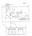
- FIG. 3 is a flowchart outlining a first mode of operation of the apparatus of FIGS. 1 and 2;
- FIG. 4 is a flowchart outlining in further detail the mode of operation of the apparatus of FIGS. 1 and 2;
- FIG. 5 a and 5 b are schematic views of intracardiac heart signals
- FIG. 6 is a schematic view of a cardiac cycle
- FIG. 7 is a schematic view of a set of cardiac cycles.
- FIG. 1 a schematic diagram of an embodiment of the apparatus for providing arrhythmia discrimination is shown.
- the apparatus 10 includes a set of electrodes 12 (seen as atrial electrode 12 a and ventricular electrode 12 b ) which are preferably located on the endocardium or epicardium of the atrium 14 and ventricle 16 of a patient's heart 18 .
- a set of leads 20 a and 20 b connect the electrodes 12 to I/O ports 22 (seen as I/O ports 22 a and 22 b ) located within a housing 24 .
- the housing 24 further includes a processor 26 , a heart signal monitor 28 to receive and compile signals from electrodes 12 and transmit them to processor 26 over communication bus 36 .
- the housing 22 also includes a treatment centre 32 , in communication with the processor 26 via communication bus 40 , to deliver a treatment protocol to the heart through the electrodes 12 .
- the housing 22 may also include a database 34 which stores a list of diagnostic tests along with a list of appropriate treatments corresponding to detected types of arrhythmia. These lists are accessed by the processor 26 via communication bus 38 .
- the processor 26 is shown in greater detail in FIG. 2.
- the processor 26 includes memory 50 , preferably in the form of First-in-First-out (FIFO) memory, to store the signals which are received from the heart signal monitor 28 .
- a central processing unit (CPU) 52 accesses the memory 50 over communication bus 54 to retrieve the stored signals and to calculate rate signals corresponding to the stored signals. After the rate signals are retrieved, they are stored in a rate memory location 56 .
- the CPU 52 may also retrieve morphology signals from the stored signals representing the shape of the heart signals which are then stored in a morphology memory location 57 .
- the rate signals are then transmitted to a comparator 58 which compares the rate signals with predetermined stored values 60 , such as a pre-stored detection threshold 62 .
- the CPU 52 accesses the database 34 via communication bus 38 , to access a diagnostic test from the list of diagnostic tests 64 .
- the CPU 52 accesses a treatment look-up table 66 within the database 34 .
- the look-up table 66 preferably includes a listing of types of arrhythmia along with their corresponding treatment.
- the apparatus 10 functions as shown schematically in FIG. 3.
- the electrodes 12 sense heart signals from their location within the heart 18 and transmit these heart signals to the I/O ports 22 (step 100 ).
- the atrial electrode 12 a and the ventricular electrode 12 b each transmit a set of heart signals to the heart signal monitor 28 .
- the number of electrodes 12 used may vary.
- the location of the electrodes 12 may also be varied within the patient's heart 18 provided that the selected location provides heart signals to be sensed.
- the I/O ports 22 After receiving the heart signals, the I/O ports 22 transmit the signals to the heart signal monitor which translates the heart signals into a format which is readable by the processor 26 such as shown in FIGS. 5 a and 5 b with FIG. 5 a showing heart signals received from the atrial electrode 12 a and FIG. 5 b showing heart signals received from the ventricular electrode 12 b.
- the formatted signals are then transmitted to the processor 26 via communication buses 36 and stored in memory 50 .
- the CPU 52 then accesses the signals and retrieves information such as rate signals from the formatted signals and extracts information from the rate signals to detect an arrhythmia state (step 102 ).
- the information and the rate signals are then stored in the rate memory location 56 .
- the rate signals and the detection threshold 62 are then sent to the comparator 58 for comparison with each other to determine when an arrhythmia state is being experienced by the heart (step 104 ).
- the detection threshold 62 is a predetermined value which is pre-stored within the processor 26 and represents a value which the heart rate is not expected to exceed.
- the processor 26 If the rate signals are lower than the detection threshold, the processor 26 simply receives the next set of formatted signals from the heart signal monitor 28 and stores them in the memory 50 before the CPU 52 accesses the signals to retrieve the rate signals for comparison with the detection threshold 62 to determine if an arrhythmia state is being experienced. However, if the rate signals are higher than the detection threshold, a check is performed to see whether the type of arrhythmia being experienced may be identified by the information contained in the rate signals (step 106 ). If the type of arrhythmia may be determined from the information in the rate signals, the appropriate treatment is identified by the processor 26 . The processor 26 identifies the appropriate treatment by accessing the treatment look-up table 66 in the database 34 .
- the processor 26 After retrieving the type of treatment, the processor 26 signals, via communication bus 40 , the treatment protocol to the treatment centre 32 which then sends out signals instructing the electrodes 12 to administer the treatment protocol, such as cardioversion therapy, to the heart (step 108 ). After administering the treatment, the electrodes 12 return to sensing and transmitting heart signals (step 109 ).
- the treatment protocol such as cardioversion therapy
- the processor 26 selects a diagnostic test (step 110 ) from the list of diagnostic tests 64 stored in the database 34 .
- the diagnostic test is used to produce stimulated heart signals which are monitored to determine the type of arrhythmia being experienced and is preferably based on the rate signals of the atrium or ventricle when the arrhythmia was detected.
- the processor 26 communicates with the treatment centre 32 to stimulate the heart according to the selected diagnostic test (step 112 ).
- the treatment centre 32 communicates with the electrodes 12 to administer the stimulation, which is preferably achieved via a pacing of the heart.
- the stimulation may be performed by only a select number of electrodes 12 and does not have to be performed by each electrode 12 . In this manner, some electrodes 12 may continue to sense and transmit heart signals to the I/O ports 22 .
- the electrodes 12 sense the heart signals (seen as stimulated heart signals) and transmit them to the I/O ports 22 (step 114 ) which, in turn, transmit them to the heart signal monitor 28 .
- the heart signal monitor 28 translates the stimulated heart signals into a format readable by the processor 26 and transmits the formatted stimulated heart signals to the processor 26 for storage in the memory 50 .
- the CPU 52 then accesses the formatted signals to retrieve information such as stimulated rate signals and morphology signals and extracts information from the stimulated rate signals to determine the type of arrhythmia being experienced (step 116 ) by comparing the stimulated rate signals with predetermined criteria. After determining the type of arrhythmia, the processor 26 determines whether or not treatment is required for the identified arrhythmia (step 118 ). If treatment is required, it is identified and administered (step 108 ), in the manner described above.
- arrhythmia which require treatment include supraventricular tachycardias such as atrial flutter, atrial fibrillation, ectopic atrial tachycardia, atrioventricular junctional re-entry, ventricular tachycardias and ventricular fibrillation.
- supraventricular tachycardias such as atrial flutter, atrial fibrillation, ectopic atrial tachycardia, atrioventricular junctional re-entry, ventricular tachycardias and ventricular fibrillation.
- there may be two or more of the above target arrhythmias simultaneously present double tachycardias or triple tachycardias etc.
- the electrodes 12 continue to sense and transmit heart signals to the I/O ports 22 (step 109 ).
- FIG. 4 The detailed operation of the apparatus 10 is exemplified in FIG. 4 using two electrodes (atrial electrode 12 a and ventricular electrode 12 b ), respectively connected to the atrium and ventricle of a patient's heart.
- heart signals are monitored to determine when an arrhythmia state is being experienced (step 200 ).
- the heart signals are sensed by the electrodes 12 and transmitted to the heart signal monitor 28 via the I/O ports 22 .
- the heart signals are then translated by the heart signal monitor 28 into a format which is readable by the processor 28 such as the electrograms shown in FIGS. 5 a and 5 b for the atrium and ventricle respectively.
- the CPU 52 retrieves the cycle length of the heart signals from the atrial electrode 12 a and the ventricular electrode 12 b by calculating the time elapsed between successive atrial electrograms 300 to determine an atrial cycle length 302 along with the time elapsed between successive ventricular electrograms 304 to determine a ventricular cycle length 306 .
- Rate signals representing an inverse of the cycle length, are then calculated and stored in the rate memory location 56 .
- morphology signals representing the shape of the heart signals may also be retrieved and stored in the morphology memory location 57 .
- the rate signals corresponding to the atrial and ventricular rates are then compared, using the comparator 58 , to the pre-stored detection threshold 62 in order to determine if the heart is experiencing an arrhythmia state. As discussed above, if the rate signals fall below the detection threshold, the processor 26 simply continues to monitor subsequent atrial 300 and ventricular electrograms 304 to determine when an arrhythmia state is being experienced. However, if either of the rate signals is above the detection threshold, the processor 26 determines that the heart is experiencing an arrhythmia state and initiates a treatment protocol. For the present embodiment, the ventricular rate signal is first compared to the detection threshold.
- the processor 26 After the processor 26 has detected an arrhythmia state (step 201 ), the processor 26 compares the atrial rate with the ventricular rate to ascertain whether the arrhythmia is determinable, such that the atrial rate is greater than the ventricular rate (step 202 ) or less than the ventricular rate (step 204 ), or not determinable, such that the atrial rate is equal to the ventricular rate (step 206 ).
- the processor 26 accesses the treatment look-up table 66 in database 34 to determine the treatment for this type of arrhythmia. After determining the type of treatment for this arrhythmia as being atrial therapy, the processor 26 communicates with the treatment centre 32 to administer this treatment protocol to the patient. The treatment centre 32 then sends signals to electrode 12 a to administer the treatment protocol (step 208 ). After the electrode 12 a administers the treatment, the electrodes 12 continue to sense and transmit heart signals (step 210 ).
- the processor 26 determines that the atrial rate is less than the ventricular rate (step 204 )
- the processor 26 accesses the look-up table 66 in the database 34 to determine the treatment for this type of arrhythmia.
- the processor 26 communicates with the treatment centre 32 to administer this treatment protocol to the patient.
- the treatment centre 32 then sends signals to electrode 12 b to administer the treatment protocol (step 212 ).
- the electrodes 12 continue to sense and transmit heart signals (step 210 ).
- the processor 26 determines that the type of arrhythmia is not determinable, or is ambiguous i.e. the atrial rate equals the ventricular rate, further arrhythmia discrimination is required to determine the type of arrhythmia and whether treatment is necessary.
- a diagnostic test is then selected from the list of diagnostic tests 64 stored in the database 34 in order to produce stimulated heart signals (step 214 ).
- the processor 26 determines from the list of tests 64 that monitoring the response of the heart to a paced atrial stimulation period shorter than the one detected will resolve the ambiguity. Accordingly, the processor 26 retrieves the measured atrial cycle length (CL) and ventricular CL when the arrhythmia was detected.
- the atrial CL is then used to determine stimulation for the treatment centre 32 to stimulate the patient's heart.
- the processor 26 After calculating the timing of the stimulation, as 50 ms less than the atrial cycle length, the processor 26 then signals the treatment centre 32 to stimulate the atrium 14 so that the atrium beats at the calculated timing as part of the diagnostic test.
- the treatment centre 32 then sends signals to electrode 12 a corresponding to a pacing of the atrium 14 at the calculated timing (step 216 ).
- both electrodes 12 a and 12 b continue to sense the heart signals, referred to as the stimulated heart signals, and transmit these signals to the I/O ports 22 .
- the stimulated heart signals are then transmitted to the heart signal monitor 28 which receives the stimulated heart signals and translates the stimulated heart signals into a readable format.
- the formatted signals are then received by the processor 26 (step 218 ).
- the stimulated ventricular rate is then calculated by inverting the cycle length of successive stimulated ventricular electrograms, in the same manner discussed above, while the stimulated atrial rate is known due to the previously calculated timing of stimulation.
- the processor 26 compares the ventricular rate to the detection threshold to determine if the stimulated ventricular rate falls below the detection threshold (step 220 ). If the stimulated ventricular rate falls below the detection threshold, the processor 26 determines that the detected arrhythmia does not require treatment and the apparatus 10 then continues to monitor heart signals to detect a subsequent arrhythmia state (step 210 ).
- the processor 26 compares the stimulated ventricular rate with the predetermined stimulated atrial rate. If the two stimulated rates are equal (step 222 ), the processor 26 accesses the treatment look-up table 66 in database 34 to determine the treatment for this type of arrhythmia. The type of treatment (in this case, atrial therapy) is retrieved from the database 34 and the processor 26 then signals the treatment centre 32 to administer atrial therapy for the arrhythmia (step 224 ). The treatment centre 32 then sends signals to electrode 12 a to administer the treatment. After the electrode 12 a administers the treatment, the electrodes 12 continue to sense and transmit heart signals (step 210 ).
- the type of treatment in this case, atrial therapy
- the processor 26 compares the rates to determine if the stimulated ventricular rate is less than the stimulated atrial rate (step 226 ). The processor 26 then calculates a stimulated ventricular CL and determines if the stimulated ventricular CL is less than the ventricular CL (the ventricular CL at the time the arrhythmia was detected) (step 228 ) or if the stimulated ventricular CL is equal to the ventricular CL (step 230 ) by comparing the two values using the comparator 58 . It will be understood that their values may be retrieved from the memory.
- the processor 26 accesses the treatment look-up table 66 in database 34 to determine the treatment for this type of arrhythmia. After determining the type of treatment for this arrhythmia as being ventricular therapy, the processor 26 communicates with the treatment centre 32 to administer this treatment to the patient. The treatment centre 32 then sends signals to electrode 12 b to administer the treatment (step 232 ). After the electrode 12 b administers the treatment, the electrodes 12 continue to sense and transmit heart signals (step 210 ).
- the processor 26 accesses the database 34 to determine the treatment for this type of arrhythmia. After determining the type of treatment for this arrhythmia as being atrial therapy, the processor 26 communicates with the treatment centre 32 to administer this treatment to the patient (step 234 ). The treatment centre 32 then sends signals to electrode 12 a to administer the treatment. After the electrode 12 a administers the treatment, the electrodes 12 continue to sense and transmit heart signals (step 210 ).
- the electrodes 12 may be located on the skin surface (around the heart) of a patient to transmit heart signals to the I/O ports 22 (step 100 ).
- the electrodes 12 each transmit a set of heart signals to the heart signal monitor 28 representing the rates and shapes of the heart signals measured at their respective locations. It will be understood that the present embodiment eliminates the need for surgery to implant the electrodes 12 and the apparatus 10 within the patient's body.
- the heart signals are monitored (step 102 ) to determine when an arrhythmia state is being experienced.
- the heart signals are sensed by the electrodes 12 and transmitted to the heart signal monitor 28 via the I/O ports 22 .
- the heart signals are then translated by the heart signal monitor 28 into a format which is readable by the processor 28 such as a cardiac cycle 250 as shown in FIG. 6.
- a normal heart beat is caused by the sinoatrial node of the heart initiating an electrical impulse to depolarize the heart and to cause the heart to contract which in turn results in a cardiac cycle 250 .
- the P wave 252 , the Q wave 254 , the R wave 256 , the S wave 258 and the T wave 260 and the intervals between these waves represent different aspects of the cardiac cycle for the heart.
- the P wave 252 and the PR interval 262 indicate atrial depolarization with a normal PR interval being 0.12 to 0.2 seconds in length.
- the QRS complex 264 represents the spread of the electrical impulse through the ventricular muscle, or depolarization and generally lasts 0.08 to 0.12 seconds.
- the ST segment 266 and the T wave 260 represent the cardiac repolarization or recovery.
- the CPU 52 retrieves a pair of rate signals by calculating the time elapsed between successive P waves 252 to determine an atrial cycle length 268 along with the time elapsed between successive R waves 256 to determine a ventricular cycle length 270 as shown in FIG. 7.
- the rate signals are then stored in the rate memory location 56 .
- the rate signals corresponding to these two rates are then compared, using the comparator 58 , to the pre-stored detection threshold 62 in order to determine if the heart is experiencing an arrhythmia state (step 104 ).
- the processor 26 simply continues to monitor subsequent cardiac cycles (step 102 ) to determine when an arrhythmia state is being experienced. However, if either of the rate signals is above the detection threshold, the processor 26 determines that the heart is experiencing an arrhythmia state.
- the processor 26 After the processor 26 has detected an arrhythmia state, the processor 26 checks whether the arrhythmia is determinable or not determinable (step 106 ). This may be performed by comparing the atrial rate with the ventricular rate.
- the processor 26 accesses the treatment look-up table 66 in database 34 to determine the treatment for this type of arrhythmia and to adminster the treatment (step 108 ). After administering the treatment, the apparatus returns to a heart signal sensing state (step 109 ).
- a diagnostic test is then selected from the list of diagnostic tests 64 stored in the database 34 in order to produce stimulated heart signals (step 110 ). After selecting the diagnostic test, the heart is stimulated (step 112 ) according to the parameters of the selected test. This stimulation may be via, for example, a mild shock to the heart, vagal stimulation or drug infusion.
- the electrodes 12 continue to sense the heart signals, referred to as the stimulated heart signals, and transmit these signals to the IO ports 22 (step 114 ).
- the stimulated heart signals are then transmitted to the heart signal monitor 28 which receives the stimulated heart signals and translates the stimulated heart signals into a cardiac cycle.
- the formatted signals are then received by the processor 26 which then extracts the rate signals for the atrial and ventricular stimulated cycle lengths in order to calculate stimulated atrial and ventricular rates.
- the stimulated atrial and ventricular rates are then monitored to determine the type of arrhythmia being experienced by the heart (step 116 ). After determining the type of arrhythmia, a check is performed to see whether or not the arrhythmia requires treatment (step 118 ). If the arrhythmia requires treatment, the treatment is identified and administered (step 108 ) and if not, the apparatus simply returns to a heart signal sensing state (step 109 ).
- arrhythmias which do not require treatment may be more readily detected and the number of unnecessary treatments reduced.
- each time treatment is administered to a patient to treat arrhythmia the patient experiences pain and discomfort. Therefore, a reduction in the number of unnecessary treatments provided to a patient may be realized by determining whether treatment is required each time an arrhythmia state is detected. As well, arrhythmias which were previously not discriminated, may be discriminated.
- the steps of stimulating the heart to create stimulated heart signals and monitoring of these signals may assist in discriminating the type of arrhythmia being experienced. Furthermore, more appropriate treatments are administered to the patient once arrhythmia is detected.
- the list of diagnostic tests may be stored within the processor 26 so that the time required to select the diagnostic test is reduced.
- the processor 26 may simply set a flag once the processor 26 has communicated the diagnostic test to the treatment centre 32 such that all heart signals received subsequent to the diagnostic test are seen as stimulated heart signals. Furthermore, if the diagnostic test causes the cycle length of the heart rate to be shortened, the expected cycle length of the retrieved stimulated rate signals may be used to identify that stimulated heart signals are being read.
- shape and morphology of the heart signals may also be retrieved from the formatted signals and used to determine the type of arrhythmia being experienced by the patient by comparing these signals to predetermined morphology or shape signals stored in the predetermined stored values 60 .
- pacing has been described as the method of stimulating the heart, other methods may also be implemented such as vagal stimulation or drug infusion.
- pacing of the heart may include subthreshold pacing, burst pacing, ultra-high frequency pacing, 60 cycle or n times 60 cycle pacing, extrastimulation, rapid overdrive pacing of the atrium or ventricle, vagal stimulation and high frequency stimulation.
Abstract
The present invention provides a method and apparatus for providing arrhythmia discrimination. Heart signals are monitored to determine when an arrhythmia state is being experienced by an individual. Once the arrhythmia state is detected, the heart of the patient is stimulated to produce stimulated heart signals. These stimulated signals are then monitored and compared with predetermined criteria in order to determine the type of arrhythmia being experienced as well as whether or not the arrhythmia requires treatment.
Description
- 1. Filed of the Invention
- The present invention is directed to medical treatment devices and more specifically to a method and apparatus for providing arrhythmia discrimination.
- 2. Description of the Prior Art
- In the field of arrhythmia treatment devices such as defibrillators, pacemakers and the like, recipients of such devices are dependent on their proper functioning for treatment of life-threatening cardiac arrhythmias. An arrhythmia is seen as any deviation from or disturbance of a normal heart rhythm. This includes an acceleration or a deceleration from the normal heart rhythm. Although known arrhythmia treatment devices attempt to discriminate between life-threatening arrhythmias, i.e. “target” arrhythmias, and those which are not life-threatening, they sometimes misclassify arrhythmias that are, in fact, benign as “target” arrhythmias. This results in inappropriate treatment being administered to the patient, generally in the form of cardioversion or “shock” therapy which is quite painful to patients. However, adjustment of the devices, by lowering a detection threshold, to minimize inappropriate treatment entails a risk of the treatment device not detecting the life-threatening target arrhythmias, which may possibly result in the death of the patient.
- Current arrhythmia treatment devices, such as implantable defibrillators, execute a detection process to monitor and analyze heart rate signals or electrocardiograms to determine when the heart rate of the patient is greater than a predetermined threshold such that arrhythmia, in the form of a tachycardia, is detected. Some prior art defibrillators such as U.S. Pat. No. 6,076,014, may also use the relative timing of heart signals from different locations within the heart such as the atrium or the ventricle to assist in the detection of other types of arrhythmia. After the arrhythmia has been detected, treatment necessary to treat the detected type of arrhythmia is administered to the patient. If an appropriate treatment cannot be determined for the detected arrhythmia, the device administers a default treatment to treat the arrhythmia in order to avoid missing a life-threatening situation. In some cases, the arrhythmia is not life-threatening and therefore the patient will receive inappropriate treatment which results in pain and discomfort.
- It is an object of the present invention to obviate and mitigate the above disadvantages.
- In an aspect of the present invention, there is provided a method of providing arrhythmia discrimination comprising the steps of receiving heart signals, representing a heart rate, from a heart; monitoring the heart signals to detect an arrhythmia state; detecting the arrhythmia state; performing a diagnostic test on the heart to produce stimulated heart signals; and monitoring the stimulated heart signals to determine the nature of the arrhythmia.
- In another aspect, there is provided apparatus for providing arrhythmia discrimination comprising a set of electrodes for sensing and transmitting heart signals from a heart; a heart signal monitor for receiving the heart signals and for translating the heart signals to processor-readable heart signals; a processor for retrieving rate signals from the processor-readable heart signals to detect an arrhythmia state based on the rate signals and for selecting a diagnostic test when the arrhythmia is detected; wherein the diagnostic test causes the heart to produce stimulated heart signals which are sensed and transmitted by the set of electrodes to the heart signal monitor for translating to processor-readable stimulated heart signals; and wherein the processor retrieves stimulated rate signals from the processor-readable stimulated heart signals and compares the stimulated rate signals with predetermined criteria to discriminate the arrhythmia.
- These and other features of the preferred embodiments of the invention will become more apparent in the following detailed description in which reference is made to the appended drawings wherein:
- FIG. 1 is a schematic diagram of an embodiment of apparatus for providing arrhythmia discrimination;
- FIG. 2 is a enlarged view of a processor and a database for use in providing arrhythmia discrimination;
- FIG. 3 is a flowchart outlining a first mode of operation of the apparatus of FIGS. 1 and 2;
- FIG. 4 is a flowchart outlining in further detail the mode of operation of the apparatus of FIGS. 1 and 2;
- FIG. 5 a and 5 b are schematic views of intracardiac heart signals;
- FIG. 6 is a schematic view of a cardiac cycle; and
- FIG. 7 is a schematic view of a set of cardiac cycles.
- Turning to FIG. 1, a schematic diagram of an embodiment of the apparatus for providing arrhythmia discrimination is shown. The
apparatus 10 includes a set of electrodes 12 (seen asatrial electrode 12 a andventricular electrode 12 b) which are preferably located on the endocardium or epicardium of theatrium 14 andventricle 16 of a patient'sheart 18. A set of leads 20 a and 20 b connect the electrodes 12 to I/O ports 22 (seen as I/O ports housing 24. Thehousing 24 further includes aprocessor 26, aheart signal monitor 28 to receive and compile signals from electrodes 12 and transmit them toprocessor 26 overcommunication bus 36. The housing 22 also includes atreatment centre 32, in communication with theprocessor 26 viacommunication bus 40, to deliver a treatment protocol to the heart through the electrodes 12. The housing 22 may also include adatabase 34 which stores a list of diagnostic tests along with a list of appropriate treatments corresponding to detected types of arrhythmia. These lists are accessed by theprocessor 26 viacommunication bus 38. - The
processor 26 is shown in greater detail in FIG. 2. Theprocessor 26 includesmemory 50, preferably in the form of First-in-First-out (FIFO) memory, to store the signals which are received from theheart signal monitor 28. A central processing unit (CPU) 52 accesses thememory 50 overcommunication bus 54 to retrieve the stored signals and to calculate rate signals corresponding to the stored signals. After the rate signals are retrieved, they are stored in arate memory location 56. TheCPU 52 may also retrieve morphology signals from the stored signals representing the shape of the heart signals which are then stored in a morphology memory location 57. The rate signals are then transmitted to acomparator 58 which compares the rate signals with predeterminedstored values 60, such as apre-stored detection threshold 62. This will be described in more detail below. Once an arrhythmia state has been detected, theCPU 52 accesses thedatabase 34 viacommunication bus 38, to access a diagnostic test from the list ofdiagnostic tests 64. In order to determine the appropriate treatment for a type of arrhythmia, theCPU 52 accesses a treatment look-up table 66 within thedatabase 34. The look-up table 66 preferably includes a listing of types of arrhythmia along with their corresponding treatment. - While U.S. Pat. 6,076,014 discloses one method of implanting the electrodes 12 and leads 20 within a patient's heart, other methods of implanting the electrodes 12 will be apparent to persons skilled in the art.
- In general terms, the
apparatus 10 functions as shown schematically in FIG. 3. The electrodes 12 sense heart signals from their location within theheart 18 and transmit these heart signals to the I/O ports 22 (step 100). Theatrial electrode 12 a and theventricular electrode 12 b each transmit a set of heart signals to theheart signal monitor 28. It will be understood that although two electrodes are shown in the present embodiment, the number of electrodes 12 used may vary. Furthermore, the location of the electrodes 12 may also be varied within the patient'sheart 18 provided that the selected location provides heart signals to be sensed. - After receiving the heart signals, the I/O ports 22 transmit the signals to the heart signal monitor which translates the heart signals into a format which is readable by the
processor 26 such as shown in FIGS. 5a and 5 b with FIG. 5a showing heart signals received from theatrial electrode 12 a and FIG. 5b showing heart signals received from theventricular electrode 12 b. - The formatted signals are then transmitted to the
processor 26 viacommunication buses 36 and stored inmemory 50. TheCPU 52 then accesses the signals and retrieves information such as rate signals from the formatted signals and extracts information from the rate signals to detect an arrhythmia state (step 102). The information and the rate signals are then stored in therate memory location 56. The rate signals and thedetection threshold 62 are then sent to thecomparator 58 for comparison with each other to determine when an arrhythmia state is being experienced by the heart (step 104). Thedetection threshold 62 is a predetermined value which is pre-stored within theprocessor 26 and represents a value which the heart rate is not expected to exceed. - If the rate signals are lower than the detection threshold, the
processor 26 simply receives the next set of formatted signals from the heart signal monitor 28 and stores them in thememory 50 before theCPU 52 accesses the signals to retrieve the rate signals for comparison with thedetection threshold 62 to determine if an arrhythmia state is being experienced. However, if the rate signals are higher than the detection threshold, a check is performed to see whether the type of arrhythmia being experienced may be identified by the information contained in the rate signals (step 106). If the type of arrhythmia may be determined from the information in the rate signals, the appropriate treatment is identified by theprocessor 26. Theprocessor 26 identifies the appropriate treatment by accessing the treatment look-up table 66 in thedatabase 34. After retrieving the type of treatment, theprocessor 26 signals, viacommunication bus 40, the treatment protocol to thetreatment centre 32 which then sends out signals instructing the electrodes 12 to administer the treatment protocol, such as cardioversion therapy, to the heart (step 108). After administering the treatment, the electrodes 12 return to sensing and transmitting heart signals (step 109). - If the type of arrhythmia is not determinable, or ambiguous, the
processor 26 selects a diagnostic test (step 110) from the list ofdiagnostic tests 64 stored in thedatabase 34. The diagnostic test is used to produce stimulated heart signals which are monitored to determine the type of arrhythmia being experienced and is preferably based on the rate signals of the atrium or ventricle when the arrhythmia was detected. - After the diagnostic test has been selected by the
processor 26, theprocessor 26 communicates with thetreatment centre 32 to stimulate the heart according to the selected diagnostic test (step 112). Thetreatment centre 32 communicates with the electrodes 12 to administer the stimulation, which is preferably achieved via a pacing of the heart. The stimulation may be performed by only a select number of electrodes 12 and does not have to be performed by each electrode 12. In this manner, some electrodes 12 may continue to sense and transmit heart signals to the I/O ports 22. - After the heart has been stimulated, the electrodes 12 sense the heart signals (seen as stimulated heart signals) and transmit them to the I/O ports 22 (step 114) which, in turn, transmit them to the heart signal monitor 28. As with heart signals, the heart signal monitor 28 translates the stimulated heart signals into a format readable by the
processor 26 and transmits the formatted stimulated heart signals to theprocessor 26 for storage in thememory 50. - The
CPU 52 then accesses the formatted signals to retrieve information such as stimulated rate signals and morphology signals and extracts information from the stimulated rate signals to determine the type of arrhythmia being experienced (step 116) by comparing the stimulated rate signals with predetermined criteria. After determining the type of arrhythmia, theprocessor 26 determines whether or not treatment is required for the identified arrhythmia (step 118). If treatment is required, it is identified and administered (step 108), in the manner described above. Examples of arrhythmia which require treatment include supraventricular tachycardias such as atrial flutter, atrial fibrillation, ectopic atrial tachycardia, atrioventricular junctional re-entry, ventricular tachycardias and ventricular fibrillation. In addition, there may be two or more of the above target arrhythmias simultaneously present (double tachycardias or triple tachycardias etc). After administering the treatment, the electrodes 12 continue to sense and transmit heart signals to the I/O ports 22 (step 109). - If treatment is not required, the electrodes 12 continue to sense and transmit heart signals to the I/O ports 22 (step 109).
- The detailed operation of the
apparatus 10 is exemplified in FIG. 4 using two electrodes (atrial electrode 12 a andventricular electrode 12 b), respectively connected to the atrium and ventricle of a patient's heart. - As described with respect to FIG. 3, heart signals are monitored to determine when an arrhythmia state is being experienced (step 200). The heart signals are sensed by the electrodes 12 and transmitted to the heart signal monitor 28 via the I/O ports 22. The heart signals are then translated by the heart signal monitor 28 into a format which is readable by the
processor 28 such as the electrograms shown in FIGS. 5a and 5 b for the atrium and ventricle respectively. - After receiving the formatted signals and storing the signals in
memory 50, theCPU 52 retrieves the cycle length of the heart signals from theatrial electrode 12 a and theventricular electrode 12 b by calculating the time elapsed between successiveatrial electrograms 300 to determine anatrial cycle length 302 along with the time elapsed between successive ventricular electrograms 304 to determine aventricular cycle length 306. Rate signals, representing an inverse of the cycle length, are then calculated and stored in therate memory location 56. Along with the rate signals, morphology signals representing the shape of the heart signals may also be retrieved and stored in the morphology memory location 57. The rate signals corresponding to the atrial and ventricular rates are then compared, using thecomparator 58, to thepre-stored detection threshold 62 in order to determine if the heart is experiencing an arrhythmia state. As discussed above, if the rate signals fall below the detection threshold, theprocessor 26 simply continues to monitor subsequent atrial 300 andventricular electrograms 304 to determine when an arrhythmia state is being experienced. However, if either of the rate signals is above the detection threshold, theprocessor 26 determines that the heart is experiencing an arrhythmia state and initiates a treatment protocol. For the present embodiment, the ventricular rate signal is first compared to the detection threshold. - After the
processor 26 has detected an arrhythmia state (step 201), theprocessor 26 compares the atrial rate with the ventricular rate to ascertain whether the arrhythmia is determinable, such that the atrial rate is greater than the ventricular rate (step 202) or less than the ventricular rate (step 204), or not determinable, such that the atrial rate is equal to the ventricular rate (step 206). - If the atrial rate is greater than the ventricular rate (step 202), the
processor 26 accesses the treatment look-up table 66 indatabase 34 to determine the treatment for this type of arrhythmia. After determining the type of treatment for this arrhythmia as being atrial therapy, theprocessor 26 communicates with thetreatment centre 32 to administer this treatment protocol to the patient. Thetreatment centre 32 then sends signals to electrode 12 a to administer the treatment protocol (step 208). After theelectrode 12 a administers the treatment, the electrodes 12 continue to sense and transmit heart signals (step 210). - If the
processor 26 determines that the atrial rate is less than the ventricular rate (step 204), theprocessor 26 accesses the look-up table 66 in thedatabase 34 to determine the treatment for this type of arrhythmia. After determining the type of treatment for this arrhythmia as being ventricular therapy/ventricular fibrillation therapy, theprocessor 26 communicates with thetreatment centre 32 to administer this treatment protocol to the patient. Thetreatment centre 32 then sends signals toelectrode 12 b to administer the treatment protocol (step 212). After theelectrode 12 b administers the treatment, the electrodes 12 continue to sense and transmit heart signals (step 210). - If the
processor 26 ascertains that the type of arrhythmia is not determinable, or is ambiguous i.e. the atrial rate equals the ventricular rate, further arrhythmia discrimination is required to determine the type of arrhythmia and whether treatment is necessary. A diagnostic test is then selected from the list ofdiagnostic tests 64 stored in thedatabase 34 in order to produce stimulated heart signals (step 214). In this embodiment, theprocessor 26 determines from the list oftests 64 that monitoring the response of the heart to a paced atrial stimulation period shorter than the one detected will resolve the ambiguity. Accordingly, theprocessor 26 retrieves the measured atrial cycle length (CL) and ventricular CL when the arrhythmia was detected. The atrial CL is then used to determine stimulation for thetreatment centre 32 to stimulate the patient's heart. After calculating the timing of the stimulation, as 50 ms less than the atrial cycle length, theprocessor 26 then signals thetreatment centre 32 to stimulate theatrium 14 so that the atrium beats at the calculated timing as part of the diagnostic test. Thetreatment centre 32 then sends signals to electrode 12 a corresponding to a pacing of theatrium 14 at the calculated timing (step 216). - During the pacing by
electrode 12 a to stimulate theatrium 14, bothelectrodes processor 26 then compares the ventricular rate to the detection threshold to determine if the stimulated ventricular rate falls below the detection threshold (step 220). If the stimulated ventricular rate falls below the detection threshold, theprocessor 26 determines that the detected arrhythmia does not require treatment and theapparatus 10 then continues to monitor heart signals to detect a subsequent arrhythmia state (step 210). - However, if the stimulated ventricular rate does not fall below the detection threshold, the
processor 26 compares the stimulated ventricular rate with the predetermined stimulated atrial rate. If the two stimulated rates are equal (step 222), theprocessor 26 accesses the treatment look-up table 66 indatabase 34 to determine the treatment for this type of arrhythmia. The type of treatment (in this case, atrial therapy) is retrieved from thedatabase 34 and theprocessor 26 then signals thetreatment centre 32 to administer atrial therapy for the arrhythmia (step 224). Thetreatment centre 32 then sends signals to electrode 12 a to administer the treatment. After theelectrode 12 a administers the treatment, the electrodes 12 continue to sense and transmit heart signals (step 210). - If the stimulated rates are not equal, the
processor 26 compares the rates to determine if the stimulated ventricular rate is less than the stimulated atrial rate (step 226). Theprocessor 26 then calculates a stimulated ventricular CL and determines if the stimulated ventricular CL is less than the ventricular CL (the ventricular CL at the time the arrhythmia was detected) (step 228) or if the stimulated ventricular CL is equal to the ventricular CL (step 230) by comparing the two values using thecomparator 58. It will be understood that their values may be retrieved from the memory. If the stimulated ventricular CL and the ventricular CL are equal (step 230), theprocessor 26 accesses the treatment look-up table 66 indatabase 34 to determine the treatment for this type of arrhythmia. After determining the type of treatment for this arrhythmia as being ventricular therapy, theprocessor 26 communicates with thetreatment centre 32 to administer this treatment to the patient. Thetreatment centre 32 then sends signals toelectrode 12 b to administer the treatment (step 232). After theelectrode 12 b administers the treatment, the electrodes 12 continue to sense and transmit heart signals (step 210). - Otherwise, if the stimulated ventricular CL is less than the ventricular CL (step 228), the
processor 26 accesses thedatabase 34 to determine the treatment for this type of arrhythmia. After determining the type of treatment for this arrhythmia as being atrial therapy, theprocessor 26 communicates with thetreatment centre 32 to administer this treatment to the patient (step 234). Thetreatment centre 32 then sends signals to electrode 12 a to administer the treatment. After theelectrode 12 a administers the treatment, the electrodes 12 continue to sense and transmit heart signals (step 210). - In another embodiment, as described with the first mode shown in FIG. 3, the electrodes 12 may be located on the skin surface (around the heart) of a patient to transmit heart signals to the I/O ports 22 (step 100). The electrodes 12 each transmit a set of heart signals to the heart signal monitor 28 representing the rates and shapes of the heart signals measured at their respective locations. It will be understood that the present embodiment eliminates the need for surgery to implant the electrodes 12 and the
apparatus 10 within the patient's body. - The heart signals are monitored (step 102) to determine when an arrhythmia state is being experienced. The heart signals are sensed by the electrodes 12 and transmitted to the heart signal monitor 28 via the I/O ports 22. The heart signals are then translated by the heart signal monitor 28 into a format which is readable by the
processor 28 such as a cardiac cycle 250 as shown in FIG. 6. - As will be understood by one skilled in the art, a normal heart beat is caused by the sinoatrial node of the heart initiating an electrical impulse to depolarize the heart and to cause the heart to contract which in turn results in a cardiac cycle 250. The
P wave 252, theQ wave 254, theR wave 256, theS wave 258 and theT wave 260 and the intervals between these waves represent different aspects of the cardiac cycle for the heart. TheP wave 252 and thePR interval 262 indicate atrial depolarization with a normal PR interval being 0.12 to 0.2 seconds in length. TheQRS complex 264 represents the spread of the electrical impulse through the ventricular muscle, or depolarization and generally lasts 0.08 to 0.12 seconds. TheST segment 266 and theT wave 260 represent the cardiac repolarization or recovery. - After receiving the formatted signals and storing the signals in
memory 50, theCPU 52 retrieves a pair of rate signals by calculating the time elapsed betweensuccessive P waves 252 to determine anatrial cycle length 268 along with the time elapsed between successive R waves 256 to determine aventricular cycle length 270 as shown in FIG. 7. The rate signals are then stored in therate memory location 56. The rate signals corresponding to these two rates are then compared, using thecomparator 58, to thepre-stored detection threshold 62 in order to determine if the heart is experiencing an arrhythmia state (step 104). As discussed above, if the rate signals fall below the detection threshold, theprocessor 26 simply continues to monitor subsequent cardiac cycles (step 102) to determine when an arrhythmia state is being experienced. However, if either of the rate signals is above the detection threshold, theprocessor 26 determines that the heart is experiencing an arrhythmia state. - After the
processor 26 has detected an arrhythmia state, theprocessor 26 checks whether the arrhythmia is determinable or not determinable (step 106). This may be performed by comparing the atrial rate with the ventricular rate. - If the arrhythmia is determinable, the
processor 26 accesses the treatment look-up table 66 indatabase 34 to determine the treatment for this type of arrhythmia and to adminster the treatment (step 108). After administering the treatment, the apparatus returns to a heart signal sensing state (step 109). - If the
processor 26 ascertains that the type of arrhythmia is not determinable, or is ambiguous i.e. the atrial rate equals the ventricular rate, further arrhythmia discrimination is required to determine the type of arrhythmia and whether treatment is necessary. A diagnostic test is then selected from the list ofdiagnostic tests 64 stored in thedatabase 34 in order to produce stimulated heart signals (step 110). After selecting the diagnostic test, the heart is stimulated (step 112) according to the parameters of the selected test. This stimulation may be via, for example, a mild shock to the heart, vagal stimulation or drug infusion. - After the heart has been stimulated, the electrodes 12 continue to sense the heart signals, referred to as the stimulated heart signals, and transmit these signals to the IO ports 22 (step 114). The stimulated heart signals are then transmitted to the heart signal monitor 28 which receives the stimulated heart signals and translates the stimulated heart signals into a cardiac cycle. The formatted signals are then received by the
processor 26 which then extracts the rate signals for the atrial and ventricular stimulated cycle lengths in order to calculate stimulated atrial and ventricular rates. - The stimulated atrial and ventricular rates are then monitored to determine the type of arrhythmia being experienced by the heart (step 116). After determining the type of arrhythmia, a check is performed to see whether or not the arrhythmia requires treatment (step 118). If the arrhythmia requires treatment, the treatment is identified and administered (step 108) and if not, the apparatus simply returns to a heart signal sensing state (step 109).
- By stimulating the patient's heart after an arrhythmia state has been detected to produce stimulated heart signals and monitoring these stimulated heart signals, arrhythmias which do not require treatment may be more readily detected and the number of unnecessary treatments reduced. As described above, each time treatment is administered to a patient to treat arrhythmia, the patient experiences pain and discomfort. Therefore, a reduction in the number of unnecessary treatments provided to a patient may be realized by determining whether treatment is required each time an arrhythmia state is detected. As well, arrhythmias which were previously not discriminated, may be discriminated. Instead of simply providing treatment by default to those arrhythmias which could not be determined, the steps of stimulating the heart to create stimulated heart signals and monitoring of these signals may assist in discriminating the type of arrhythmia being experienced. Furthermore, more appropriate treatments are administered to the patient once arrhythmia is detected.
- Alternatively, the list of diagnostic tests may be stored within the
processor 26 so that the time required to select the diagnostic test is reduced. - In another embodiment, in order to distinguish between heart signals and stimulated heart signals, the
processor 26 may simply set a flag once theprocessor 26 has communicated the diagnostic test to thetreatment centre 32 such that all heart signals received subsequent to the diagnostic test are seen as stimulated heart signals. Furthermore, if the diagnostic test causes the cycle length of the heart rate to be shortened, the expected cycle length of the retrieved stimulated rate signals may be used to identify that stimulated heart signals are being read. - It will be understood that other information such as shape and morphology of the heart signals may also be retrieved from the formatted signals and used to determine the type of arrhythmia being experienced by the patient by comparing these signals to predetermined morphology or shape signals stored in the predetermined stored values 60.
- It will also be understood that the parameters of the
detection threshold 62, the treatment look-up table 66 or the list of diagnostic tests may be changed. - Furthermore, although pacing has been described as the method of stimulating the heart, other methods may also be implemented such as vagal stimulation or drug infusion.
- The different treatments which are available for treating arrhythmia will be well known to those skilled in the art and is not restricted to those listed above. It will be understood that pacing of the heart may include subthreshold pacing, burst pacing, ultra-high frequency pacing, 60 cycle or
n times 60 cycle pacing, extrastimulation, rapid overdrive pacing of the atrium or ventricle, vagal stimulation and high frequency stimulation. - Although the invention has been described with reference to certain specific embodiments, various modifications thereof will be apparent to those skilled in the art without departing from the spirit and scope of the invention as outlined in the claims appended hereto.
Claims (13)
1. A method of providing arrhythmia discrimination comprising the steps of:
receiving signals from a heart;
monitoring said signals to detect a condition indicative of at least one of a number arrhythmia states;
detecting said arrhythmia state;
performing a diagnostic test on said heart to produce stimulated heart signals;
monitoring said stimulated heart signals to determine which of said states is detected.
2. The method of claim 1 wherein said step of performing said diagnostic test comprises the steps of:
selecting a diagnostic test corresponding to one of said arrhythmia states;
calculating a level of stimulation for said heart; and
stimulating said heart at said level of stimulation.
3. The method of claim 2 wherein said step of stimulating said heart is selected from the group comprising of pacing, vagal stimulation and drug infusion.
4. The method of claim 1 wherein said step of calculating a level of stimulation for said heart comprises the steps of:
calculating a cycle length of said heart rate; and
subtracting a predetermined value from said cycle length to produce a new cycle length.
5. The method of claim 1 wherein said step of monitoring said heart signals comprises the steps of:
retrieving rate signals from said heart signals; and
determining when said rate signals exceed a detection threshold.
6. The method of claim 1 wherein said step of monitoring said stimulated heart signals comprises the steps of:
retrieving stimulated signals from said stimulated heart signals;
comparing said stimulated signals with predetermined criteria to determine said arrhythmia.
7. The method of claim 6 wherein said stimulated signals are stimulated rate signals or morphology signals.
8. The method of claim 1 further comprising the step of comparing said arrhythmia with a list of target arrhythmias and treatments to determine treatment for said arrhythmia.
9. The method of claim 1 wherein said heart signals comprise atrial and ventricular heart signals.
10. Apparatus for providing arrhythmia discrimination comprising:
a set of electrodes for sensing and transmitting signals from a heart;
a heart signal monitor for receiving said signals and for translating said signals to processor-readable signals;
a processor for retrieving rate signals from said processor-readable heart signals to detect a condition indicative of an arrhythmia state based on said rate signals and for selecting a diagnostic test when said arrhythmia is detected;
wherein said diagnostic test causes said heart to produce stimulated heart signals which are sensed and transmitted by said set of electrodes to said heart signal monitor for translating to processor-readable stimulated heart signals; and
wherein said processor retrieves stimulated signals from said processor-readable stimulated heart signals and compares said stimulated signals with predetermined criteria to discriminate said arrhythmia state.
11. The apparatus of claim 10 further comprising a treatment centre for treating said arrhythmia.
12. The apparatus of claim 10 further comprises a database for storing treatments associated with a list of arrhythmias wherein after said arrhythmia has been discriminated, said processor accesses said database to compare said arrhythmia with said list of arrhythmias to determine treatment for said arrhythmia.
13. The apparatus of claim 10 wherein stimulated signals are stimulated rate signals or stimulated morphology signals.
Priority Applications (6)
| Application Number | Priority Date | Filing Date | Title |
|---|---|---|---|
| US10/117,187 US20030191404A1 (en) | 2002-04-08 | 2002-04-08 | Method and apparatus for providing arrhythmia discrimination |
| PCT/CA2003/000496 WO2003086536A1 (en) | 2002-04-08 | 2003-04-08 | Method and apparatus for providing arrhythmia discrimination |
| JP2003583544A JP2005528939A (en) | 2002-04-08 | 2003-04-08 | Method and apparatus for providing arrhythmia discrimination |
| EP03709530A EP1494755A1 (en) | 2002-04-08 | 2003-04-08 | Method and apparatus for providing arrhythmia discrimination |
| CN038131501A CN1658927A (en) | 2002-04-08 | 2003-04-08 | Method and apparatus for providing arrhythmia discrimination |
| AU2003213961A AU2003213961A1 (en) | 2002-04-08 | 2003-04-08 | Method and apparatus for providing arrhythmia discrimination |
Applications Claiming Priority (1)
| Application Number | Priority Date | Filing Date | Title |
|---|---|---|---|
| US10/117,187 US20030191404A1 (en) | 2002-04-08 | 2002-04-08 | Method and apparatus for providing arrhythmia discrimination |
Publications (1)
| Publication Number | Publication Date |
|---|---|
| US20030191404A1 true US20030191404A1 (en) | 2003-10-09 |
Family
ID=28674143
Family Applications (1)
| Application Number | Title | Priority Date | Filing Date |
|---|---|---|---|
| US10/117,187 Abandoned US20030191404A1 (en) | 2002-04-08 | 2002-04-08 | Method and apparatus for providing arrhythmia discrimination |
Country Status (6)
| Country | Link |
|---|---|
| US (1) | US20030191404A1 (en) |
| EP (1) | EP1494755A1 (en) |
| JP (1) | JP2005528939A (en) |
| CN (1) | CN1658927A (en) |
| AU (1) | AU2003213961A1 (en) |
| WO (1) | WO2003086536A1 (en) |
Cited By (45)
| Publication number | Priority date | Publication date | Assignee | Title |
|---|---|---|---|---|
| WO2008094800A1 (en) * | 2007-01-31 | 2008-08-07 | Medtronic, Inc. | Implantable medical device and method for physiological event monitoring |
| US20090259269A1 (en) * | 2008-04-09 | 2009-10-15 | Brown Mark L | Method and apparatus for detecting and treating tachyarrhythmias incorporating diagnostic/therapeutic pacing techniques |
| US7657312B2 (en) | 2003-11-03 | 2010-02-02 | Cardiac Pacemakers, Inc. | Multi-site ventricular pacing therapy with parasympathetic stimulation |
| WO2010085391A1 (en) | 2009-01-23 | 2010-07-29 | Medtronic, Inc. | Hybrid single-chamber to simultaneous pacing method for discrimination of tachycardias |
| US7783353B2 (en) | 2003-12-24 | 2010-08-24 | Cardiac Pacemakers, Inc. | Automatic neural stimulation modulation based on activity and circadian rhythm |
| US20110077703A1 (en) * | 2009-09-30 | 2011-03-31 | Medtronic, Inc. | Pace discrimination of tachycardia using atrial-ventricular pacing |
| US20110077704A1 (en) * | 2009-09-30 | 2011-03-31 | Medtronic, Inc. | Pace discrimination of tachycardia using atrial-ventricular pacing |
| US20110077705A1 (en) * | 2009-09-30 | 2011-03-31 | Medtronic, Inc | Pace discrimination of tachycardia using atrial-ventricular pacing |
| US8000793B2 (en) | 2003-12-24 | 2011-08-16 | Cardiac Pacemakers, Inc. | Automatic baroreflex modulation based on cardiac activity |
| US8024050B2 (en) | 2003-12-24 | 2011-09-20 | Cardiac Pacemakers, Inc. | Lead for stimulating the baroreceptors in the pulmonary artery |
| US8126560B2 (en) | 2003-12-24 | 2012-02-28 | Cardiac Pacemakers, Inc. | Stimulation lead for stimulating the baroreceptors in the pulmonary artery |
| US8170668B2 (en) | 2006-07-14 | 2012-05-01 | Cardiac Pacemakers, Inc. | Baroreflex sensitivity monitoring and trending for tachyarrhythmia detection and therapy |
| EP2510872A1 (en) * | 2011-04-13 | 2012-10-17 | BIOTRONIK SE & Co. KG | Method of determination of a type of arrhythmia in a heart of a patient and respective device |
| US8391970B2 (en) | 2007-08-27 | 2013-03-05 | The Feinstein Institute For Medical Research | Devices and methods for inhibiting granulocyte activation by neural stimulation |
| US8412338B2 (en) | 2008-11-18 | 2013-04-02 | Setpoint Medical Corporation | Devices and methods for optimizing electrode placement for anti-inflamatory stimulation |
| US8612002B2 (en) | 2009-12-23 | 2013-12-17 | Setpoint Medical Corporation | Neural stimulation devices and systems for treatment of chronic inflammation |
| US8729129B2 (en) | 2004-03-25 | 2014-05-20 | The Feinstein Institute For Medical Research | Neural tourniquet |
| US8788034B2 (en) | 2011-05-09 | 2014-07-22 | Setpoint Medical Corporation | Single-pulse activation of the cholinergic anti-inflammatory pathway to treat chronic inflammation |
| US8886339B2 (en) | 2009-06-09 | 2014-11-11 | Setpoint Medical Corporation | Nerve cuff with pocket for leadless stimulator |
| US8914114B2 (en) | 2000-05-23 | 2014-12-16 | The Feinstein Institute For Medical Research | Inhibition of inflammatory cytokine production by cholinergic agonists and vagus nerve stimulation |
| US8996116B2 (en) | 2009-10-30 | 2015-03-31 | Setpoint Medical Corporation | Modulation of the cholinergic anti-inflammatory pathway to treat pain or addiction |
| US9061155B2 (en) | 2010-12-23 | 2015-06-23 | Medtronic, Inc. | Implanted device data to guide ablation therapy |
| US9095715B2 (en) | 2010-12-23 | 2015-08-04 | Medtronic, Inc. | Implanted device data to guide ablation therapy |
| US9211410B2 (en) | 2009-05-01 | 2015-12-15 | Setpoint Medical Corporation | Extremely low duty-cycle activation of the cholinergic anti-inflammatory pathway to treat chronic inflammation |
| US9211409B2 (en) | 2008-03-31 | 2015-12-15 | The Feinstein Institute For Medical Research | Methods and systems for reducing inflammation by neuromodulation of T-cell activity |
| US9572983B2 (en) | 2012-03-26 | 2017-02-21 | Setpoint Medical Corporation | Devices and methods for modulation of bone erosion |
| US9662490B2 (en) | 2008-03-31 | 2017-05-30 | The Feinstein Institute For Medical Research | Methods and systems for reducing inflammation by neuromodulation and administration of an anti-inflammatory drug |
| US9675804B2 (en) | 2012-05-31 | 2017-06-13 | Zoll Medical Corporation | Medical monitoring and treatment device with external pacing |
| US9833621B2 (en) | 2011-09-23 | 2017-12-05 | Setpoint Medical Corporation | Modulation of sirtuins by vagus nerve stimulation |
| US10314501B2 (en) | 2016-01-20 | 2019-06-11 | Setpoint Medical Corporation | Implantable microstimulators and inductive charging systems |
| US10328266B2 (en) | 2012-05-31 | 2019-06-25 | Zoll Medical Corporation | External pacing device with discomfort management |
| US10583304B2 (en) | 2016-01-25 | 2020-03-10 | Setpoint Medical Corporation | Implantable neurostimulator having power control and thermal regulation and methods of use |
| US10596367B2 (en) | 2016-01-13 | 2020-03-24 | Setpoint Medical Corporation | Systems and methods for establishing a nerve block |
| US10695569B2 (en) | 2016-01-20 | 2020-06-30 | Setpoint Medical Corporation | Control of vagal stimulation |
| US10912712B2 (en) | 2004-03-25 | 2021-02-09 | The Feinstein Institutes For Medical Research | Treatment of bleeding by non-invasive stimulation |
| US11051744B2 (en) | 2009-11-17 | 2021-07-06 | Setpoint Medical Corporation | Closed-loop vagus nerve stimulation |
| US11097107B2 (en) | 2012-05-31 | 2021-08-24 | Zoll Medical Corporation | External pacing device with discomfort management |
| US11173307B2 (en) | 2017-08-14 | 2021-11-16 | Setpoint Medical Corporation | Vagus nerve stimulation pre-screening test |
| US11207518B2 (en) | 2004-12-27 | 2021-12-28 | The Feinstein Institutes For Medical Research | Treating inflammatory disorders by stimulation of the cholinergic anti-inflammatory pathway |
| US11260229B2 (en) | 2018-09-25 | 2022-03-01 | The Feinstein Institutes For Medical Research | Methods and apparatuses for reducing bleeding via coordinated trigeminal and vagal nerve stimulation |
| US11311725B2 (en) | 2014-10-24 | 2022-04-26 | Setpoint Medical Corporation | Systems and methods for stimulating and/or monitoring loci in the brain to treat inflammation and to enhance vagus nerve stimulation |
| US11344724B2 (en) | 2004-12-27 | 2022-05-31 | The Feinstein Institutes For Medical Research | Treating inflammatory disorders by electrical vagus nerve stimulation |
| US11406833B2 (en) | 2015-02-03 | 2022-08-09 | Setpoint Medical Corporation | Apparatus and method for reminding, prompting, or alerting a patient with an implanted stimulator |
| US11471681B2 (en) | 2016-01-20 | 2022-10-18 | Setpoint Medical Corporation | Batteryless implantable microstimulators |
| US11938324B2 (en) | 2020-05-21 | 2024-03-26 | The Feinstein Institutes For Medical Research | Systems and methods for vagus nerve stimulation |
Families Citing this family (8)
| Publication number | Priority date | Publication date | Assignee | Title |
|---|---|---|---|---|
| JP4563785B2 (en) * | 2004-12-03 | 2010-10-13 | テルモ株式会社 | Heart treatment equipment |
| JP4630653B2 (en) * | 2004-12-10 | 2011-02-09 | テルモ株式会社 | Heart treatment equipment |
| US8224436B2 (en) * | 2007-04-02 | 2012-07-17 | Cardiac Research, Inc. | Unidirectional neural stimulation systems, devices and methods |
| US9392948B2 (en) * | 2011-12-09 | 2016-07-19 | The Regents Of The University Of California | System and method of identifying sources for biological rhythms |
| KR101251081B1 (en) | 2011-02-17 | 2013-04-05 | (의료)길의료재단 | A shockable signal detection method of automated external defibrillator using neural network with weighted fuzzy membership function |
| US8165666B1 (en) * | 2011-05-02 | 2012-04-24 | Topera, Inc. | System and method for reconstructing cardiac activation information |
| US9744364B2 (en) * | 2013-09-25 | 2017-08-29 | Medtronic, Inc. | Method and apparatus for automatic configuration of implantable medical devices |
| JP6510660B2 (en) * | 2015-02-06 | 2019-05-08 | カーディアック ペースメイカーズ, インコーポレイテッド | System and method for treating cardiac arrhythmias |
Citations (10)
| Publication number | Priority date | Publication date | Assignee | Title |
|---|---|---|---|---|
| US4830006A (en) * | 1986-06-17 | 1989-05-16 | Intermedics, Inc. | Implantable cardiac stimulator for detection and treatment of ventricular arrhythmias |
| US5184615A (en) * | 1991-03-08 | 1993-02-09 | Telectronics Pacing Systems, Inc. | Apparatus and method for detecting abnormal cardiac rhythms using evoked potential measurements in an arrhythmia control system |
| US5243980A (en) * | 1992-06-30 | 1993-09-14 | Medtronic, Inc. | Method and apparatus for discrimination of ventricular and supraventricular tachycardia |
| US5411530A (en) * | 1992-11-13 | 1995-05-02 | Akhtar; Masood | Sensing algorithm for anti-tachycardia devices using dual chamber sensing |
| US5620471A (en) * | 1995-06-16 | 1997-04-15 | Pacesetter, Inc. | System and method for discriminating between atrial and ventricular arrhythmias and for applying cardiac therapy therefor |
| US5766225A (en) * | 1996-06-28 | 1998-06-16 | Medtronic, Inc. | System and method for distinguishing between VF/VT bradycardia or asystole |
| US5891169A (en) * | 1994-07-30 | 1999-04-06 | Biotronik Mess- Und Therapiegeraete Gmbh | Method of processing signals characteristic of cardiac activity and an associated device |
| US5925067A (en) * | 1997-12-11 | 1999-07-20 | Pacesetter, Inc. | Automatic capture detection during non-invasive programmed stimulation of a patient's heart |
| US6035232A (en) * | 1997-05-07 | 2000-03-07 | Biotronik Mess-Und Therapiegeraete Gmbh & Co. | Device for determining tachycardiac heart rhythm disturbances |
| US6076014A (en) * | 1997-08-01 | 2000-06-13 | Sulzer Intermedics, Inc. | Cardiac stimulator and defibrillator with means for identifying cardiac rhythm disorder and chamber of origin |
Family Cites Families (1)
| Publication number | Priority date | Publication date | Assignee | Title |
|---|---|---|---|---|
| US5782876A (en) * | 1996-04-15 | 1998-07-21 | Medtronic, Inc. | Method and apparatus using windows and an index value for identifying cardic arrhythmias |
-
2002
- 2002-04-08 US US10/117,187 patent/US20030191404A1/en not_active Abandoned
-
2003
- 2003-04-08 EP EP03709530A patent/EP1494755A1/en not_active Withdrawn
- 2003-04-08 JP JP2003583544A patent/JP2005528939A/en active Pending
- 2003-04-08 WO PCT/CA2003/000496 patent/WO2003086536A1/en not_active Application Discontinuation
- 2003-04-08 AU AU2003213961A patent/AU2003213961A1/en not_active Abandoned
- 2003-04-08 CN CN038131501A patent/CN1658927A/en active Pending
Patent Citations (11)
| Publication number | Priority date | Publication date | Assignee | Title |
|---|---|---|---|---|
| US4830006A (en) * | 1986-06-17 | 1989-05-16 | Intermedics, Inc. | Implantable cardiac stimulator for detection and treatment of ventricular arrhythmias |
| US4830006B1 (en) * | 1986-06-17 | 1997-10-28 | Intermedics Inc | Implantable cardiac stimulator for detection and treatment of ventricular arrhythmias |
| US5184615A (en) * | 1991-03-08 | 1993-02-09 | Telectronics Pacing Systems, Inc. | Apparatus and method for detecting abnormal cardiac rhythms using evoked potential measurements in an arrhythmia control system |
| US5243980A (en) * | 1992-06-30 | 1993-09-14 | Medtronic, Inc. | Method and apparatus for discrimination of ventricular and supraventricular tachycardia |
| US5411530A (en) * | 1992-11-13 | 1995-05-02 | Akhtar; Masood | Sensing algorithm for anti-tachycardia devices using dual chamber sensing |
| US5891169A (en) * | 1994-07-30 | 1999-04-06 | Biotronik Mess- Und Therapiegeraete Gmbh | Method of processing signals characteristic of cardiac activity and an associated device |
| US5620471A (en) * | 1995-06-16 | 1997-04-15 | Pacesetter, Inc. | System and method for discriminating between atrial and ventricular arrhythmias and for applying cardiac therapy therefor |
| US5766225A (en) * | 1996-06-28 | 1998-06-16 | Medtronic, Inc. | System and method for distinguishing between VF/VT bradycardia or asystole |
| US6035232A (en) * | 1997-05-07 | 2000-03-07 | Biotronik Mess-Und Therapiegeraete Gmbh & Co. | Device for determining tachycardiac heart rhythm disturbances |
| US6076014A (en) * | 1997-08-01 | 2000-06-13 | Sulzer Intermedics, Inc. | Cardiac stimulator and defibrillator with means for identifying cardiac rhythm disorder and chamber of origin |
| US5925067A (en) * | 1997-12-11 | 1999-07-20 | Pacesetter, Inc. | Automatic capture detection during non-invasive programmed stimulation of a patient's heart |
Cited By (85)
| Publication number | Priority date | Publication date | Assignee | Title |
|---|---|---|---|---|
| US10561846B2 (en) | 2000-05-23 | 2020-02-18 | The Feinstein Institutes For Medical Research | Inhibition of inflammatory cytokine production by cholinergic agonists and vagus nerve stimulation |
| US8914114B2 (en) | 2000-05-23 | 2014-12-16 | The Feinstein Institute For Medical Research | Inhibition of inflammatory cytokine production by cholinergic agonists and vagus nerve stimulation |
| US9987492B2 (en) | 2000-05-23 | 2018-06-05 | The Feinstein Institute For Medical Research | Inhibition of inflammatory cytokine production by cholinergic agonists and vagus nerve stimulation |
| US10166395B2 (en) | 2000-05-23 | 2019-01-01 | The Feinstein Institute For Medical Research | Inhibition of inflammatory cytokine production by cholinergic agonists and vagus nerve stimulation |
| US7657312B2 (en) | 2003-11-03 | 2010-02-02 | Cardiac Pacemakers, Inc. | Multi-site ventricular pacing therapy with parasympathetic stimulation |
| US8571655B2 (en) | 2003-11-03 | 2013-10-29 | Cardiac Pacemakers, Inc. | Multi-site ventricular pacing therapy with parasympathetic stimulation |
| US8874211B2 (en) | 2003-12-23 | 2014-10-28 | Cardiac Pacemakers, Inc. | Hypertension therapy based on activity and circadian rhythm |
| US8457746B2 (en) | 2003-12-24 | 2013-06-04 | Cardiac Pacemakers, Inc. | Implantable systems and devices for providing cardiac defibrillation and apnea therapy |
| US9950170B2 (en) | 2003-12-24 | 2018-04-24 | Cardiac Pacemakers, Inc. | System for providing stimulation pattern to modulate neural activity |
| US8024050B2 (en) | 2003-12-24 | 2011-09-20 | Cardiac Pacemakers, Inc. | Lead for stimulating the baroreceptors in the pulmonary artery |
| US8126560B2 (en) | 2003-12-24 | 2012-02-28 | Cardiac Pacemakers, Inc. | Stimulation lead for stimulating the baroreceptors in the pulmonary artery |
| US8626301B2 (en) | 2003-12-24 | 2014-01-07 | Cardiac Pacemakers, Inc. | Automatic baroreflex modulation based on cardiac activity |
| US8285389B2 (en) | 2003-12-24 | 2012-10-09 | Cardiac Pacemakers, Inc. | Automatic neural stimulation modulation based on motion and physiological activity |
| US10369367B2 (en) | 2003-12-24 | 2019-08-06 | Cardiac Pacemakers, Inc. | System for providing stimulation pattern to modulate neural activity |
| US7783353B2 (en) | 2003-12-24 | 2010-08-24 | Cardiac Pacemakers, Inc. | Automatic neural stimulation modulation based on activity and circadian rhythm |
| US11154716B2 (en) | 2003-12-24 | 2021-10-26 | Cardiac Pacemakers, Inc. | System for providing stimulation pattern to modulate neural activity |
| US8000793B2 (en) | 2003-12-24 | 2011-08-16 | Cardiac Pacemakers, Inc. | Automatic baroreflex modulation based on cardiac activity |
| US9561373B2 (en) | 2003-12-24 | 2017-02-07 | Cardiac Pacemakers, Inc. | System to stimulate a neural target and a heart |
| US9265948B2 (en) | 2003-12-24 | 2016-02-23 | Cardiac Pacemakers, Inc. | Automatic neural stimulation modulation based on activity |
| US8473076B2 (en) | 2003-12-24 | 2013-06-25 | Cardiac Pacemakers, Inc. | Lead for stimulating the baroreceptors in the pulmonary artery |
| US8729129B2 (en) | 2004-03-25 | 2014-05-20 | The Feinstein Institute For Medical Research | Neural tourniquet |
| US10912712B2 (en) | 2004-03-25 | 2021-02-09 | The Feinstein Institutes For Medical Research | Treatment of bleeding by non-invasive stimulation |
| US11207518B2 (en) | 2004-12-27 | 2021-12-28 | The Feinstein Institutes For Medical Research | Treating inflammatory disorders by stimulation of the cholinergic anti-inflammatory pathway |
| US11344724B2 (en) | 2004-12-27 | 2022-05-31 | The Feinstein Institutes For Medical Research | Treating inflammatory disorders by electrical vagus nerve stimulation |
| US8170668B2 (en) | 2006-07-14 | 2012-05-01 | Cardiac Pacemakers, Inc. | Baroreflex sensitivity monitoring and trending for tachyarrhythmia detection and therapy |
| US8540642B2 (en) | 2007-01-31 | 2013-09-24 | Medtronic, Inc. | Implantable medical device and method for physiological event monitoring |
| WO2008094800A1 (en) * | 2007-01-31 | 2008-08-07 | Medtronic, Inc. | Implantable medical device and method for physiological event monitoring |
| US8391970B2 (en) | 2007-08-27 | 2013-03-05 | The Feinstein Institute For Medical Research | Devices and methods for inhibiting granulocyte activation by neural stimulation |
| US9662490B2 (en) | 2008-03-31 | 2017-05-30 | The Feinstein Institute For Medical Research | Methods and systems for reducing inflammation by neuromodulation and administration of an anti-inflammatory drug |
| US9211409B2 (en) | 2008-03-31 | 2015-12-15 | The Feinstein Institute For Medical Research | Methods and systems for reducing inflammation by neuromodulation of T-cell activity |
| US20090259269A1 (en) * | 2008-04-09 | 2009-10-15 | Brown Mark L | Method and apparatus for detecting and treating tachyarrhythmias incorporating diagnostic/therapeutic pacing techniques |
| US8706220B2 (en) * | 2008-04-09 | 2014-04-22 | Medtronic, Inc. | Method and apparatus for detecting and treating tachyarrhythmias incorporating diagnostic/therapeutic pacing techniques |
| US8412338B2 (en) | 2008-11-18 | 2013-04-02 | Setpoint Medical Corporation | Devices and methods for optimizing electrode placement for anti-inflamatory stimulation |
| WO2010085391A1 (en) | 2009-01-23 | 2010-07-29 | Medtronic, Inc. | Hybrid single-chamber to simultaneous pacing method for discrimination of tachycardias |
| US8332032B2 (en) | 2009-01-23 | 2012-12-11 | Medtronic, Inc. | Hybrid single-chamber to simultaneous pacing method for discrimination of tachycardias |
| US9211410B2 (en) | 2009-05-01 | 2015-12-15 | Setpoint Medical Corporation | Extremely low duty-cycle activation of the cholinergic anti-inflammatory pathway to treat chronic inflammation |
| US9849286B2 (en) | 2009-05-01 | 2017-12-26 | Setpoint Medical Corporation | Extremely low duty-cycle activation of the cholinergic anti-inflammatory pathway to treat chronic inflammation |
| US8886339B2 (en) | 2009-06-09 | 2014-11-11 | Setpoint Medical Corporation | Nerve cuff with pocket for leadless stimulator |
| US9174041B2 (en) | 2009-06-09 | 2015-11-03 | Setpoint Medical Corporation | Nerve cuff with pocket for leadless stimulator |
| US10716936B2 (en) | 2009-06-09 | 2020-07-21 | Setpoint Medical Corporation | Nerve cuff with pocket for leadless stimulator |
| US10220203B2 (en) | 2009-06-09 | 2019-03-05 | Setpoint Medical Corporation | Nerve cuff with pocket for leadless stimulator |
| US9700716B2 (en) | 2009-06-09 | 2017-07-11 | Setpoint Medical Corporation | Nerve cuff with pocket for leadless stimulator |
| US20110077704A1 (en) * | 2009-09-30 | 2011-03-31 | Medtronic, Inc. | Pace discrimination of tachycardia using atrial-ventricular pacing |
| US20110077705A1 (en) * | 2009-09-30 | 2011-03-31 | Medtronic, Inc | Pace discrimination of tachycardia using atrial-ventricular pacing |
| US8718762B2 (en) | 2009-09-30 | 2014-05-06 | Medtronic, Inc. | Pace discrimination of tachycardia using atrial-ventricular pacing |
| US8306620B2 (en) | 2009-09-30 | 2012-11-06 | Medtronic, Inc. | Pace discrimination of tachycardia using atrial-ventricular pacing |
| US20110077703A1 (en) * | 2009-09-30 | 2011-03-31 | Medtronic, Inc. | Pace discrimination of tachycardia using atrial-ventricular pacing |
| US8831723B2 (en) | 2009-09-30 | 2014-09-09 | Medtronic, Inc. | Pace discrimination of tachycardia using atrial-ventricular pacing |
| US8996116B2 (en) | 2009-10-30 | 2015-03-31 | Setpoint Medical Corporation | Modulation of the cholinergic anti-inflammatory pathway to treat pain or addiction |
| US11051744B2 (en) | 2009-11-17 | 2021-07-06 | Setpoint Medical Corporation | Closed-loop vagus nerve stimulation |
| US11110287B2 (en) | 2009-12-23 | 2021-09-07 | Setpoint Medical Corporation | Neural stimulation devices and systems for treatment of chronic inflammation |
| US9162064B2 (en) | 2009-12-23 | 2015-10-20 | Setpoint Medical Corporation | Neural stimulation devices and systems for treatment of chronic inflammation |
| US8855767B2 (en) | 2009-12-23 | 2014-10-07 | Setpoint Medical Corporation | Neural stimulation devices and systems for treatment of chronic inflammation |
| US8612002B2 (en) | 2009-12-23 | 2013-12-17 | Setpoint Medical Corporation | Neural stimulation devices and systems for treatment of chronic inflammation |
| US10384068B2 (en) | 2009-12-23 | 2019-08-20 | Setpoint Medical Corporation | Neural stimulation devices and systems for treatment of chronic inflammation |
| US9993651B2 (en) | 2009-12-23 | 2018-06-12 | Setpoint Medical Corporation | Neural stimulation devices and systems for treatment of chronic inflammation |
| US9061155B2 (en) | 2010-12-23 | 2015-06-23 | Medtronic, Inc. | Implanted device data to guide ablation therapy |
| US9095715B2 (en) | 2010-12-23 | 2015-08-04 | Medtronic, Inc. | Implanted device data to guide ablation therapy |
| US8788026B2 (en) | 2011-04-13 | 2014-07-22 | Biotronik Se & Co. Kg | Methods and devices for determination of heart arrhythmia type |
| EP2510872A1 (en) * | 2011-04-13 | 2012-10-17 | BIOTRONIK SE & Co. KG | Method of determination of a type of arrhythmia in a heart of a patient and respective device |
| US8788034B2 (en) | 2011-05-09 | 2014-07-22 | Setpoint Medical Corporation | Single-pulse activation of the cholinergic anti-inflammatory pathway to treat chronic inflammation |
| US9833621B2 (en) | 2011-09-23 | 2017-12-05 | Setpoint Medical Corporation | Modulation of sirtuins by vagus nerve stimulation |
| US10449358B2 (en) | 2012-03-26 | 2019-10-22 | Setpoint Medical Corporation | Devices and methods for modulation of bone erosion |
| US9572983B2 (en) | 2012-03-26 | 2017-02-21 | Setpoint Medical Corporation | Devices and methods for modulation of bone erosion |
| US11857327B2 (en) | 2012-05-31 | 2024-01-02 | Zoll Medical Corporation | Medical monitoring and treatment device with external pacing |
| US10898095B2 (en) | 2012-05-31 | 2021-01-26 | Zoll Medical Corporation | Medical monitoring and treatment device with external pacing |
| US9675804B2 (en) | 2012-05-31 | 2017-06-13 | Zoll Medical Corporation | Medical monitoring and treatment device with external pacing |
| US11097107B2 (en) | 2012-05-31 | 2021-08-24 | Zoll Medical Corporation | External pacing device with discomfort management |
| US10384066B2 (en) | 2012-05-31 | 2019-08-20 | Zoll Medical Corporation | Medical monitoring and treatment device with external pacing |
| US10328266B2 (en) | 2012-05-31 | 2019-06-25 | Zoll Medical Corporation | External pacing device with discomfort management |
| US11311725B2 (en) | 2014-10-24 | 2022-04-26 | Setpoint Medical Corporation | Systems and methods for stimulating and/or monitoring loci in the brain to treat inflammation and to enhance vagus nerve stimulation |
| US11406833B2 (en) | 2015-02-03 | 2022-08-09 | Setpoint Medical Corporation | Apparatus and method for reminding, prompting, or alerting a patient with an implanted stimulator |
| US11278718B2 (en) | 2016-01-13 | 2022-03-22 | Setpoint Medical Corporation | Systems and methods for establishing a nerve block |
| US10596367B2 (en) | 2016-01-13 | 2020-03-24 | Setpoint Medical Corporation | Systems and methods for establishing a nerve block |
| US10695569B2 (en) | 2016-01-20 | 2020-06-30 | Setpoint Medical Corporation | Control of vagal stimulation |
| US10314501B2 (en) | 2016-01-20 | 2019-06-11 | Setpoint Medical Corporation | Implantable microstimulators and inductive charging systems |
| US11471681B2 (en) | 2016-01-20 | 2022-10-18 | Setpoint Medical Corporation | Batteryless implantable microstimulators |
| US11547852B2 (en) | 2016-01-20 | 2023-01-10 | Setpoint Medical Corporation | Control of vagal stimulation |
| US10583304B2 (en) | 2016-01-25 | 2020-03-10 | Setpoint Medical Corporation | Implantable neurostimulator having power control and thermal regulation and methods of use |
| US11383091B2 (en) | 2016-01-25 | 2022-07-12 | Setpoint Medical Corporation | Implantable neurostimulator having power control and thermal regulation and methods of use |
| US11173307B2 (en) | 2017-08-14 | 2021-11-16 | Setpoint Medical Corporation | Vagus nerve stimulation pre-screening test |
| US11890471B2 (en) | 2017-08-14 | 2024-02-06 | Setpoint Medical Corporation | Vagus nerve stimulation pre-screening test |
| US11260229B2 (en) | 2018-09-25 | 2022-03-01 | The Feinstein Institutes For Medical Research | Methods and apparatuses for reducing bleeding via coordinated trigeminal and vagal nerve stimulation |
| US11857788B2 (en) | 2018-09-25 | 2024-01-02 | The Feinstein Institutes For Medical Research | Methods and apparatuses for reducing bleeding via coordinated trigeminal and vagal nerve stimulation |
| US11938324B2 (en) | 2020-05-21 | 2024-03-26 | The Feinstein Institutes For Medical Research | Systems and methods for vagus nerve stimulation |
Also Published As
| Publication number | Publication date |
|---|---|
| CN1658927A (en) | 2005-08-24 |
| AU2003213961A1 (en) | 2003-10-27 |
| JP2005528939A (en) | 2005-09-29 |
| EP1494755A1 (en) | 2005-01-12 |
| WO2003086536A1 (en) | 2003-10-23 |
Similar Documents
| Publication | Publication Date | Title |
|---|---|---|
| US20030191404A1 (en) | Method and apparatus for providing arrhythmia discrimination | |
| US7266409B2 (en) | Method and apparatus for determining oversensing in a medical device | |
| JP4625463B2 (en) | Method and apparatus for detecting and identifying arrhythmia | |
| US5713932A (en) | Method and apparatus for determining atrial lead disclocation and confirming diagnosis of atrial tachyarrhythimias | |
| EP1737535B1 (en) | Automated template generation algorithm for implantable device | |
| US7333855B2 (en) | Method and apparatus for determining oversensing in a medical device | |
| JP4542094B2 (en) | How to eliminate ventricular proarrhythmic effects caused by atrial therapy | |
| US7167747B2 (en) | Identification of oversensing using sinus R-wave template | |
| JP4988553B2 (en) | How to generate a template in an implantable device | |
| WO2006060763A1 (en) | Arrhythmia termination detection based on beat pattern | |
| EP1177013A1 (en) | Apparatus for determining atrial lead dislocation | |
| US7809439B2 (en) | Spectrum-driven arrhythmia treatment method | |
| US7873414B2 (en) | Patient characteristic based adaptive anti-tachy pacing programming | |
| US7181273B2 (en) | Tachycardia synchronization delays |
Legal Events
| Date | Code | Title | Description |
|---|---|---|---|
| AS | Assignment |
Owner name: MEDTRONIC, INC., MINNESOTA Free format text: ASSIGNMENT OF ASSIGNORS INTEREST;ASSIGNOR:KLEIN, GEORGE J.;REEL/FRAME:016061/0613 Effective date: 20030508 |
|
| STCB | Information on status: application discontinuation |
Free format text: ABANDONED -- FAILURE TO RESPOND TO AN OFFICE ACTION |