US20030191453A1 - Catheter assembly - Google Patents
Catheter assembly Download PDFInfo
- Publication number
- US20030191453A1 US20030191453A1 US10/406,761 US40676103A US2003191453A1 US 20030191453 A1 US20030191453 A1 US 20030191453A1 US 40676103 A US40676103 A US 40676103A US 2003191453 A1 US2003191453 A1 US 2003191453A1
- Authority
- US
- United States
- Prior art keywords
- fluid
- elongated tube
- apertures
- catheter assembly
- air
- Prior art date
- Legal status (The legal status is an assumption and is not a legal conclusion. Google has not performed a legal analysis and makes no representation as to the accuracy of the status listed.)
- Abandoned
Links
Images


Classifications
-
- A—HUMAN NECESSITIES
- A61—MEDICAL OR VETERINARY SCIENCE; HYGIENE
- A61M—DEVICES FOR INTRODUCING MEDIA INTO, OR ONTO, THE BODY; DEVICES FOR TRANSDUCING BODY MEDIA OR FOR TAKING MEDIA FROM THE BODY; DEVICES FOR PRODUCING OR ENDING SLEEP OR STUPOR
- A61M25/00—Catheters; Hollow probes
- A61M25/0067—Catheters; Hollow probes characterised by the distal end, e.g. tips
- A61M25/0068—Static characteristics of the catheter tip, e.g. shape, atraumatic tip, curved tip or tip structure
-
- A—HUMAN NECESSITIES
- A61—MEDICAL OR VETERINARY SCIENCE; HYGIENE
- A61M—DEVICES FOR INTRODUCING MEDIA INTO, OR ONTO, THE BODY; DEVICES FOR TRANSDUCING BODY MEDIA OR FOR TAKING MEDIA FROM THE BODY; DEVICES FOR PRODUCING OR ENDING SLEEP OR STUPOR
- A61M25/00—Catheters; Hollow probes
- A61M25/0043—Catheters; Hollow probes characterised by structural features
- A61M2025/0057—Catheters delivering medicament other than through a conventional lumen, e.g. porous walls or hydrogel coatings
-
- A—HUMAN NECESSITIES
- A61—MEDICAL OR VETERINARY SCIENCE; HYGIENE
- A61M—DEVICES FOR INTRODUCING MEDIA INTO, OR ONTO, THE BODY; DEVICES FOR TRANSDUCING BODY MEDIA OR FOR TAKING MEDIA FROM THE BODY; DEVICES FOR PRODUCING OR ENDING SLEEP OR STUPOR
- A61M25/00—Catheters; Hollow probes
- A61M25/0043—Catheters; Hollow probes characterised by structural features
- A61M25/005—Catheters; Hollow probes characterised by structural features with embedded materials for reinforcement, e.g. wires, coils, braids
-
- A—HUMAN NECESSITIES
- A61—MEDICAL OR VETERINARY SCIENCE; HYGIENE
- A61M—DEVICES FOR INTRODUCING MEDIA INTO, OR ONTO, THE BODY; DEVICES FOR TRANSDUCING BODY MEDIA OR FOR TAKING MEDIA FROM THE BODY; DEVICES FOR PRODUCING OR ENDING SLEEP OR STUPOR
- A61M25/00—Catheters; Hollow probes
- A61M25/0067—Catheters; Hollow probes characterised by the distal end, e.g. tips
- A61M25/0068—Static characteristics of the catheter tip, e.g. shape, atraumatic tip, curved tip or tip structure
- A61M25/007—Side holes, e.g. their profiles or arrangements; Provisions to keep side holes unblocked
-
- A—HUMAN NECESSITIES
- A61—MEDICAL OR VETERINARY SCIENCE; HYGIENE
- A61M—DEVICES FOR INTRODUCING MEDIA INTO, OR ONTO, THE BODY; DEVICES FOR TRANSDUCING BODY MEDIA OR FOR TAKING MEDIA FROM THE BODY; DEVICES FOR PRODUCING OR ENDING SLEEP OR STUPOR
- A61M25/00—Catheters; Hollow probes
- A61M25/0067—Catheters; Hollow probes characterised by the distal end, e.g. tips
- A61M25/008—Strength or flexibility characteristics of the catheter tip
Definitions
- the present invention generally relates to a fluid delivery system for delivering fluid to an anatomical site. More specifically, the present invention relates to a catheter assembly of the fluid delivery system utilizing a plurality of apertures for delivering the fluid to the anatomical site.
- a typical fluid delivery system comprises a fluid source to hold fluid such as medication.
- a fluid conduit conveys the fluid from the fluid source to a catheter assembly.
- the catheter assembly conveys the fluid to an anatomical site of a patient.
- a connector couples the catheter assembly and fluid conduit.
- a typical catheter assembly comprises an elongated tube defining a central lumen and a plurality of apertures at an infusion section of the elongated tube to convey the fluid from the fluid source to the anatomical site.
- the apertures provide a corridor for the fluid to enter the anatomical site.
- An open proximal end of the elongated tube is connected to the connector and a closed distal end of the elongated tube is inserted in the anatomical site.
- the elongated tube extending from the open proximal end at the connector to the closed distal end at the anatomical site can comprise several sections either integrally formed together, or attached to one another by additional connectors. Either way, the central lumen conveys the fluid from the fluid source to the anatomical site via the plurality of apertures in the infusion section.
- connection of the fluid conduit to the fluid source and the connector may be one source of air infiltration.
- the connection of the catheter assembly to the connector may be another source.
- the air moves toward the closed distal end, the fluid is obstructed from exiting out of the plurality of apertures in the infusion section of the elongated tube.
- the air becomes permanently entrapped in the central lumen at the infusion section. The air either settles at the closed distal end of the elongated tube or gets trapped along the central lumen in the proximity of the apertures and permanently blocks a portion of the plurality of apertures in the infusion section.
- the priming of the elongated tube removes a large percentage of the air
- the air rushes in through the open proximal end when the user removes the syringe and makes the connection with the fluid conduit.
- the priming removes most of the air
- air can still be infiltrated at connection points such as between the connector and the elongated tube.
- the present invention provides a catheter assembly for conveying fluid from a fluid source to an anatomical site.
- a fluid connection mechanism provides fluid communication between the catheter assembly and the fluid source.
- the catheter assembly comprises an elongated tube having an open proximal end and a closed distal end. The open proximal end is coupled to the fluid connection mechanism to receive the fluid. The closed distal end enters the anatomical site to deliver the fluid.
- the elongated tube defines a central lumen and a plurality of apertures between the open proximal and closed distal ends. The fluid from the fluid source enters the elongated tube through the central lumen at the open proximal end and exits the elongated tube through the plurality of apertures near the closed distal end.
- An air elimination device is coupled to the elongated tube between the open proximal end and the plurality of apertures to remove trapped air from the central lumen to ensure that the air does not reach the closed distal end or block the fluid from exiting through the plurality of aperture to the anatomical site.
- the catheter assembly of the present invention overcomes the disadvantages of the prior art by removing air from the fluid in the fluid delivery system thereby eliminating obstruction of the plurality of apertures in the elongated tube and providing uniform fluid delivery. Uniform fluid delivery, especially when delivering medication for pain relief is essential in providing adequate pain relief to a patient.
- FIG. 1 is an elevational view of one embodiment of the fluid delivery system of the present invention
- FIG. 1A is an elevational view of another embodiment of the fluid delivery system
- FIG. 2 is cross-sectional view of a catheter assembly of the fluid delivery system taken along line 2 - 2 of FIG. 1 to illustrate a reinforcing coil of the catheter assembly;
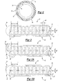
- FIG. 3 is a fragmentary perspective view of one embodiment of an elongated tube of the catheter assembly of the present invention illustrating an infusion section of the elongated tube;
- FIG. 3A is a fragmentary perspective view of another embodiment of the elongated tube of the catheter assembly of the present invention illustrating the infusion section of the elongated tube defining a vent hole;
- FIG. 3B is a fragmentary perspective view of another embodiment of the elongated tube of the catheter assembly of the present invention illustrating the infusion section of the elongated tube defining a vent hole in a tip of the elongated tube;
- FIG. 4 is an elevational view of an alternative embodiment of the fluid delivery system of the present invention.
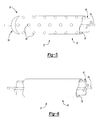
- FIG. 5 is a fragmentary perspective view of an elongated tube of a catheter assembly of the alternative embodiment illustrating a support in an infusion section of the elongated tube;
- FIG. 6 is a fragmentary perspective view of the elongated tube of the catheter assembly of the alternative embodiment illustrating the support in a continuous section of the elongated tube;
- FIG. 7 is a cross-sectional view taken along the line 7 - 7 of FIG. 4 to illustrate a guide system of the present invention
- FIG. 8 is a cross-sectional view taken along the line 8 - 8 of FIG. 4 to illustrate the guide system of the present invention.
- FIG. 9 is a perspective view of a support tip of the guide system of the present invention.
- a fluid delivery system for delivering fluid to an anatomical site 10 of a patient 11 is generally shown at 12 .
- the fluid can be medication, irrigation fluid such as a saline solution, and the like.
- the fluid delivery system could be used to supply the fluid to the anatomical site 10 , to irrigate the anatomical site 10 , or other related functions.
- the fluid delivery system 12 includes a fluid source 14 to supply the fluid to be delivered to the anatomical site 10 .
- the fluid source 14 can include any mechanism or manner to store and/or deliver the fluid to the anatomical site 10 of the patient. Such mechanisms may include, but are not limited to, pain medication pumps, intravenous bags, syringes to inject fluid, and the like.
- FIG. 1 illustrates the use of an intravenous bag as the fluid source 14
- FIG. 1A illustrates the use of a pain medication pump as the fluid source 14 .
- a fluid conduit 18 is in fluid communication with the fluid source 14 and conveys the fluid from the fluid source 14 to a catheter assembly 20 .
- the fluid conduit 18 includes a proximal end 29 coupled to the fluid source 14 and a distal end 30 coupled to the catheter assembly 20 .
- the fluid conduit 18 is generally illustrated as one possible configuration of a tube set 15 for the fluid delivery system 12 .
- any tube set i.e., a series of tubes and connectors, may be used to couple the fluid source 14 to the catheter assembly 20 .
- the fluid conduit 18 may include multiple tubes, a stopcock to control a flow rate of the fluid, a converter adapted to couple different diameter tubes, and the like.
- the fluid conduit 18 may be made from any number of materials, as recognized by those skilled in the art, including, but not limited to, any appropriate flexible polymer, sterilizable and biocompatible in the case of medical applications. Some typical materials include silicone, polyamide, polyether block amide, polyethylene, urethane, polyurethane, fluorinated ethylene propylene, PTFE, other fluoropolymers, and the like.
- a fluid connection mechanism 16 such as a connector 16 couples the fluid conduit 18 , i.e., tube set 15 , with the catheter assembly 20 . It should be appreciated that the catheter assembly 20 may directly engage the fluid source 14 by other well-known fluid connection mechanisms including, but not limited to, bonding, welding, or by being integrally formed therewith. Hence, eliminating the need for a fluid conduit 18 and connector 16 .
- the connector 16 comprises a first connector portion 16 A engaging the fluid conduit 18 at the distal end 30 and a second connector portion 16 B engaging the catheter assembly 20 .
- the connector portions 16 A, 16 B interlock to form the connector 16 thereby operatively interconnecting the fluid source 14 with the catheter assembly 20 .
- the connector portions 16 A, 16 B are preferably Luer-lock quick connect fittings.
- the connector portions 16 A, 16 B may be threaded fittings, snap fittings, or any type of fittings used by those skilled in the art to interlock the fluid conduit 18 and the catheter assembly 20 .
- the connector 16 may be made from any number of materials, as recognized by those skilled in the art, including, but not limited to, any appropriate polymer, sterilizable and biocompatible in the case of medical applications. Some typical materials include silicone, polyamide, polyether block amide, polyethylene, urethane, polyurethane, fluorinated ethylene propylene, PTFE, other fluoropolymers, and the like.
- the catheter assembly 20 includes an elongated tube 22 in fluid communication with the fluid source 14 to convey the fluid from the fluid source 14 to the anatomical site 10 .
- the elongated tube 22 extends between an open proximal end 32 and a closed distal end 34 .
- the open proximal end 32 engages the second connector portion 16 B.
- the open proximal end 32 is scaled to the second connector portion 16 B to provide a fluid-tight seal therewith.
- the second connector portion 16 B may be integrally formed with the elongated tube 22 at the open proximal end 32 or the second connector portion 16 B may be welded to the elongated tube 22 at the open proximal end 32 by way of a solvent weld, ultrasonic weld, thermal weld, adhesive, or the like.
- the elongated tube 22 defines a central lumen 24 and a plurality of apertures 38 therein for conveying the fluid from the fluid source 14 to the anatomical site 10 .
- a continuous section 40 and an infusion section 42 define the elongated tube 22 .
- the continuous section 40 extends from the open proximal end 32 to an intermediate point 44 and the infusion section 42 extends from the intermediate point 44 to the closed distal end 34 . It is to be appreciated that the differentiation between the continuous and infusion sections 40 , 42 is for descriptive purposes and does not indicate that the elongated tube 22 is discontinued or interrupted at the intermediate point 44 .
- the continuous section 40 is free of apertures, while the plurality of apertures 38 are defined in the infusion section 42 to deliver the fluid to the anatomical site 10 .
- each of the plurality of apertures 38 preferably have a diameter 46 between 0.0001 inches to 0.025 inches to convey the fluid from the central lumen 24 to the anatomical site 10 . It is to be understood, however, that the present invention can be used with any sized aperture 38 .
- the apertures 38 preferably assume a circular shape, but may take on a variety of shapes including elliptical, rectangular, triangular, or a combination of two or more different shapes.
- the apertures 38 may also be in the form of slots. See FIG. 3B.
- the plurality of apertures 38 are preferably laser-drilled into the elongated tube 22 , but alternative methods may also be used to form the apertures 38 .
- the elongated tube 22 may further define a vent hole 37 distal to the plurality of apertures 38 .
- the vent hole 37 is used to remove residual air that may otherwise may be trapped in the central lumen 24 of the elongated tube 22 between a tip 41 of the elongated tube 22 at the distal end 34 and the plurality of apertures 38 .
- air is forced out through the plurality of apertures 38 and the vent hole 37 .
- the vent hole 37 is defined between the plurality of apertures 38 and the tip 41 .
- the plurality of apertures 38 are axially and equally spaced from one another along said elongated tube by a first length L1.
- the vent hole 37 is axially spaced from said plurality of apertures by a second length L2.
- the second length L2 is shorter than the first length L1.
- This configuration allows the plurality of apertures 38 to maintain uniform fluid delivery along the infusion section 42 , while still providing a vent for air that may be trapped near the tip 41 .
- a small space is still available for air to be trapped, but this space is reduced considerably by the use of the vent hole 37 .
- the vent hole 37 in the embodiment of FIG. 3A assumes the same size and shape as the apertures 38 .
- the vent hole 37 is centrally positioned in the tip 41 and has a diameter smaller than the plurality of apertures 38 .
- the vent holes of FIGS. 3A and 3B are also laser-drilled into the elongated tube 22 .
- the apertures 38 illustrated in FIGS. 3 - 3 B are radially disposed from a central axis of the elongated tube 22 by one hundred twenty degrees, as illustrated. Hence, in these embodiments, three apertures 38 lie in each of a plurality of axially spaced planes (not illustrated) that are perpendicular to the central axis. The axially spaced planes are spaced by the length L1.
- the elongated tube 22 can be made from any number of materials including, but not limited to, any appropriate flexible polymer, sterilizable and biocompatible in the case of medical applications. Some typical materials include silicone, polyamide, polyether block amide, polyethylene, urethane, polyurethane, fluorinated ethylene propylene, PTFE, other fluoropolymers, and the like.
- an air elimination device 28 such as an air filter, is coupled to the elongated tube 22 between the open proximal end 32 and the plurality of apertures 38 to remove air from the central lumen 24 . This ensures that air does not reach the infusion section 42 and block the fluid from exiting through the plurality of apertures 38 to the anatomical site 10 . As previously discussed, air trapped in the infusion section 42 can obstruct one or more of the plurality of apertures 38 resulting in non-uniform fluid delivery. As can be appreciated by those skilled in the art, uniform fluid delivery is important in many medical procedures.
- the size of the plurality of apertures 38 is usually too small to permit the air to exit the central lumen 24 through the plurality of apertures 38 into the anatomical site 10 , at least under normal operating pressures.
- excess pressure such as by priming the catheter assembly 20 , is required to force any air from the central lumen 24 through the plurality of apertures 38 .
- the air elimination device 28 is in fluid communication with the central lumen 24 of the catheter assembly 20 .
- the air elimination device 28 separates any air or gas from the fluid and allows the air-free fluid to continue through the elongated tube 22 , while expelling the air to the atmosphere.
- the air elimination device 28 includes a liquid-permeable, gas-impermeable filter (not shown) and a liquid-impermeable, gas-permeable filter (not shown) positioned within a filter housing 39 to filter or remove any air from the fluid to facilitate uniform fluid delivery via the plurality of apertures 38 .
- the filter housing 39 is coupled to the elongated tube 22 and defines an inlet port 43 , a vent port 45 , and an outlet port 47 .
- the filter housing 39 may be one piece or multiple pieces bonded together using well-known methods.
- the air or gas that is prevented from exiting the filter housing then passes through the liquid-impermeable, gas-permeable filter and exits to the atmosphere through the vent port 45 .
- the filtered fluid continues from the outlet port 47 to the infusion section 42 .
- the liquid-permeable, gas-impermeable filter is a barrier to the outlet port 47 and the liquid-impermeable, air-permeable filter is a barrier to the vent port 45 .
- Seals 49 are placed between the elongated tube 22 and the filter housing 39 at both the inlet port 43 and the outlet port 47 . These seals 49 ensure that air cannot enter the catheter assembly 20 by way of connection between the elongated tube 22 and the air elimination device 28 . Hence, a closed fluid path is defined along said elongated tube 22 between the open proximal end 32 and the plurality of apertures 38 .
- the seals 49 may be solvent welds, ultrasonic welds, thermal welds, adhesives, and the like, or the seals 49 may result from the filter housing 39 being integrally molded with the elongated tube 22 . In this embodiment, there are no other connections distal to the air elimination device 28 . This further reduces the chance for air to enter the central lumen 24 at the infusion section 42 and block fluid flow through the plurality of apertures 38 .
- the air elimination device 28 can be made from any number of materials.
- the filter housing 39 may be made from any appropriate polymer or metal, sterilizable and biocompatible in the case of medical applications. Some typical materials include acrylic, ABS, polycarbonate, polypropylene, PVC, acetal, polyethylent, and the like.
- the filters described above may be a combination of a hydrophilic membrane and a hydrophobic membrane, or a composite membrane with combined characteristics. Materials for the filters may include, but are not limited to, PTFE, polyethersulfone, nylon, acrylic, polysulfone, and polypropylene. Factors such as sterilization, strength, flexibility, and weight may be taken into consideration in determining the materials to be used.
- the material used for the air elimination device 28 is not intended to limit the present invention.
- Suitable air elimination devices 28 for use in the fluid delivery system 12 of the present invention are shown in U.S. Pat. No. 4,571,244 to Knighton and U.S. Pat. No. 6,503,225 to Kirsch et al., both herein incorporated by reference.
- a reinforcing coil 57 is positioned in the central lumen 24 between the air elimination device 28 and the tip 41 . See FIGS. 2 and 3- 3 B.
- the reinforcing coil 57 freely floats within the central lumen 24 to reinforce the elongated tube 22 to prevent kinking along the infusion section 42 .
- the reinforcing coil 57 has spaced convolutions in an unstretched state. The fluid moves through and along the reinforcing coil 57 .
- the reinforcing coil 57 may be made from any appropriate metal, sterilizable, biocompatible, and rust-resistant in the case of medical applications, such as stainless steel, and the like.
- the fluid delivery system 12 is the same as the previous embodiments set forth above, with three notable exceptions.
- the tube set 15 of this alternative embodiment includes additional tubes and connectors.
- a second connector 19 similar to the connector 16 , couples the fluid conduit 18 to a second fluid conduit 23 , and the catheter assembly 16 is coupled to the second fluid conduit 23 .
- the air elimination device 28 is coupled to the second fluid conduit 23 of the tube set 15 .
- a guide system is illustrated for inserting the catheter assembly 20 into the anatomical site 10 .
- a housing 26 defining a priming port 25 is coupled to the tube set 15 .
- the priming port 25 provides a one-way valve, or check valve, to allow a user to prime the catheter assembly 20 prior to use, i.e., the priming port 25 is in fluid communication with the central lumen 24 .
- the housing 26 is a T-shaped or Y-shaped fitting that permits the flow of fluid therethrough to the central lumen 24 .
- the housing defines an inlet port 33 for receiving the fluid from the second fluid conduit 23 and an outlet port 35 for conveying the fluid back to the second fluid conduit 23 . Priming the catheter assembly 20 removes the air from the catheter assembly 20 to ensure uniform fluid delivery.
- the user primes the catheter assembly 20 by injecting the fluid at a high pressure into the priming port 25 , thus driving the air out through the plurality of apertures 38 .
- a syringe 51 is used to inject the fluid into the priming port 25 , as shown in FIG. 4.
- the housing 26 may be made from any appropriate polymer or metal, sterilizable and biocompatible in the case of medical applications. Some typical materials include acrylic, ABS, polycarbonate, polypropylene, PVC, acetal, polyethylent, and the like.
- the one-way valve or check valve may be made from any appropriate material, sterilizable and biocompatible in the case of medical applications. Some typical materials include, silicone, PVC, nitrile, latex, neoprene, urethane, polyurethane, fluoropolymers, and the like.
- the priming port 25 may assume any configuration that effectively allows the user to prime the catheter assembly 20 .
- the guide system for inserting the catheter assembly 20 into the anatomical site 10 is generally illustrated.
- the guide system includes a support 48 having a plurality of ribs 50 radially extending from a base 52 of the support 48 .
- the support 48 extends longitudinally through the central lumen 24 of the elongated tube 22 such that the plurality of ribs 50 radially extend from the base 52 toward an inner surface 36 of the elongated tube 22 .
- the support 48 partially performs the function of the reinforcing coil 57 in the previously described embodiment.
- the support 48 essentially divides the central lumen 24 into a plurality of lumens 54 to convey the fluid to the anatomical site 10 .
- a support tip 56 is formed at a distal end of the support 48 .
- the support tip 56 is integrally formed with the support 48 .
- the elongated tube 22 is sealed about the support 48 and support tip 56 such that the fluid that flows through the plurality of lumens 54 can only be discharged through the plurality of apertures 38 .
- the distal end 34 of the elongated tube 22 in this embodiment is open and abuts a ledge 55 of the support tip 56 .
- the elongated tube 22 is sealed to the support tip 56 at the ledge 55 , as shown by the hidden lines in FIG. 9.
- the base 52 of the support 48 defines a guide wire channel 58 to receive the guide wire 59 .
- the support 48 and support tip 56 can be formed from a variety of materials, giving due consideration to the goals of flexibility, weight, strength, and the like. Suitable materials include nylon, polyamide, Teflon, and the like.
- any suitable configuration should provide for sliding the catheter assembly 20 , via the guide wire channel 58 , over the guide wire 59 into the anatomical site, removing the guide wire 59 from the guide wire channel 58 once the catheter assembly 20 is in place in the anatomical site, and then occluding fluid flow through the guide wire channel 58 into the anatomical site.
- the air elimination device 28 functions to remove any additional air that may be introduced in the fluid proximally to the air elimination device 28 during use.
- the embodiment illustrated in FIG. 4 may be practiced without the guide system.
- the catheter assembly 20 illustrated in FIGS. 1, 1A, 2 , and 3 A- 3 B may be used in the embodiment of the fluid delivery system 12 of FIG. 4.
- one of the air elimination devices 28 either on the tube set 15 , or the elongated tube 22 , would be eliminated.
- the housing 26 with priming port 25 may be coupled to the fluid conduit 18 of the embodiment illustrated in FIGS. 1, 1 A, 2 , and 3 - 3 B. Either way, the combination of the housing 26 with the priming port 25 and the air elimination device 28 distal to the priming port 25 is used to remove unwanted air.
- the catheter assembly 20 is not limited to a single tube unit, that is, a single lumen.
- a multiple tube catheter assembly may be used that includes two or more tubes from several fluid sources converging into a single catheter assembly.
- a single fluid source may be connected onto a one-inlet/multiple outlet adapter so that a catheter assembly may be connected to each outlet to provide fluid delivery to multiple anatomical sites.
- the embodiments of the fluid delivery system 12 described herein are not limited in application.
- each of the embodiments may be used in high-pressure and high-flow rate systems, low-pressure and low-flow rate systems, or any combination thereof.
Abstract
A catheter assembly for conveying fluid from a fluid source to an anatomical site. A connector portion couples the catheter assembly to the fluid source. The catheter assembly comprises an elongated tube having an open proximal end engaging the connector portion and a closed distal end for inserting into the anatomical site. The elongated tube defines a central lumen and a plurality of apertures in an infusion section thereof to convey the fluid from the central lumen to the anatomical site. An air elimination device is coupled to the elongated tube between the connector portion and the infusion section. Seals are placed between the air elimination device and the elongated tube to prevent air from entering the central lumen of the elongated tube distally of the air elimination device and blocking fluid flow through the plurality of apertures into the anatomical site.
Description
- This application claims the benefit of U.S. Provisional Patent Application Serial No. 60/370,067, filed Apr. 3, 2002.
- The present invention generally relates to a fluid delivery system for delivering fluid to an anatomical site. More specifically, the present invention relates to a catheter assembly of the fluid delivery system utilizing a plurality of apertures for delivering the fluid to the anatomical site.
- A typical fluid delivery system comprises a fluid source to hold fluid such as medication. A fluid conduit conveys the fluid from the fluid source to a catheter assembly. The catheter assembly conveys the fluid to an anatomical site of a patient. A connector couples the catheter assembly and fluid conduit.
- A typical catheter assembly comprises an elongated tube defining a central lumen and a plurality of apertures at an infusion section of the elongated tube to convey the fluid from the fluid source to the anatomical site. The apertures provide a corridor for the fluid to enter the anatomical site.
- An open proximal end of the elongated tube is connected to the connector and a closed distal end of the elongated tube is inserted in the anatomical site. The elongated tube extending from the open proximal end at the connector to the closed distal end at the anatomical site can comprise several sections either integrally formed together, or attached to one another by additional connectors. Either way, the central lumen conveys the fluid from the fluid source to the anatomical site via the plurality of apertures in the infusion section.
- Unfortunately, air is easily introduced into the central lumen of the elongated tube due to the connections made throughout the fluid delivery system. For example, the connection of the fluid conduit to the fluid source and the connector may be one source of air infiltration. The connection of the catheter assembly to the connector may be another source. As the air moves toward the closed distal end, the fluid is obstructed from exiting out of the plurality of apertures in the infusion section of the elongated tube. Ultimately, due to the small diameter of the apertures, the air becomes permanently entrapped in the central lumen at the infusion section. The air either settles at the closed distal end of the elongated tube or gets trapped along the central lumen in the proximity of the apertures and permanently blocks a portion of the plurality of apertures in the infusion section.
- Current pain management pump systems used with catheter assemblies utilize devices to remove air from the pump system upstream of a restrictor orifice. However, the devices used in such systems are upstream of one or more connections to the fluid conduit, connector, or catheter assembly. Thus, air infiltrates the connections and moves through the central lumen to the infusion section of the tube as previously described. Alternatively, to remove the air, a user primes the elongated tube using a syringe by injecting the fluid at a high flow rate and pressure into the open proximal end of the elongated tube while the elongated tube is disconnected from the connector. This action is intended to drive or push the air out through the plurality of apertures. Many problems are associated with this activity. For instance, even if the priming of the elongated tube removes a large percentage of the air, the air rushes in through the open proximal end when the user removes the syringe and makes the connection with the fluid conduit. In addition, assuming the priming removes most of the air, air can still be infiltrated at connection points such as between the connector and the elongated tube. Hence, even if the elongated tube is primed, not all of the air can be removed in current systems.
- Accordingly, there is a need in the art to prevent the air from transcending through the central lumen of the elongated tube and restricting the uniform flow of fluid out of the plurality of apertures at the infusion section of the elongated tube.
- The present invention provides a catheter assembly for conveying fluid from a fluid source to an anatomical site. A fluid connection mechanism provides fluid communication between the catheter assembly and the fluid source. The catheter assembly comprises an elongated tube having an open proximal end and a closed distal end. The open proximal end is coupled to the fluid connection mechanism to receive the fluid. The closed distal end enters the anatomical site to deliver the fluid. The elongated tube defines a central lumen and a plurality of apertures between the open proximal and closed distal ends. The fluid from the fluid source enters the elongated tube through the central lumen at the open proximal end and exits the elongated tube through the plurality of apertures near the closed distal end. An air elimination device is coupled to the elongated tube between the open proximal end and the plurality of apertures to remove trapped air from the central lumen to ensure that the air does not reach the closed distal end or block the fluid from exiting through the plurality of aperture to the anatomical site.
- The catheter assembly of the present invention overcomes the disadvantages of the prior art by removing air from the fluid in the fluid delivery system thereby eliminating obstruction of the plurality of apertures in the elongated tube and providing uniform fluid delivery. Uniform fluid delivery, especially when delivering medication for pain relief is essential in providing adequate pain relief to a patient.
- Advantages of the present invention will be readily appreciated as the same becomes better understood by reference to the following detailed description when considered in connection with the accompanying drawings wherein:
- FIG. 1 is an elevational view of one embodiment of the fluid delivery system of the present invention;
- FIG. 1A is an elevational view of another embodiment of the fluid delivery system;
- FIG. 2 is cross-sectional view of a catheter assembly of the fluid delivery system taken along line 2-2 of FIG. 1 to illustrate a reinforcing coil of the catheter assembly;
- FIG. 3 is a fragmentary perspective view of one embodiment of an elongated tube of the catheter assembly of the present invention illustrating an infusion section of the elongated tube;
- FIG. 3A is a fragmentary perspective view of another embodiment of the elongated tube of the catheter assembly of the present invention illustrating the infusion section of the elongated tube defining a vent hole;
- FIG. 3B is a fragmentary perspective view of another embodiment of the elongated tube of the catheter assembly of the present invention illustrating the infusion section of the elongated tube defining a vent hole in a tip of the elongated tube;
- FIG. 4 is an elevational view of an alternative embodiment of the fluid delivery system of the present invention;
- FIG. 5 is a fragmentary perspective view of an elongated tube of a catheter assembly of the alternative embodiment illustrating a support in an infusion section of the elongated tube;
- FIG. 6 is a fragmentary perspective view of the elongated tube of the catheter assembly of the alternative embodiment illustrating the support in a continuous section of the elongated tube;
- FIG. 7 is a cross-sectional view taken along the line 7-7 of FIG. 4 to illustrate a guide system of the present invention;
- FIG. 8 is a cross-sectional view taken along the line 8-8 of FIG. 4 to illustrate the guide system of the present invention; and
- FIG. 9 is a perspective view of a support tip of the guide system of the present invention.
- Referring to the Figures, wherein like numerals indicate like or corresponding parts throughout the several views, a fluid delivery system for delivering fluid to an
anatomical site 10 of apatient 11 is generally shown at 12. It is to be appreciated that the fluid can be medication, irrigation fluid such as a saline solution, and the like. The fluid delivery system could be used to supply the fluid to theanatomical site 10, to irrigate theanatomical site 10, or other related functions. - Referring to FIGS. 1 and 1A, the
fluid delivery system 12 includes afluid source 14 to supply the fluid to be delivered to theanatomical site 10. Thefluid source 14 can include any mechanism or manner to store and/or deliver the fluid to theanatomical site 10 of the patient. Such mechanisms may include, but are not limited to, pain medication pumps, intravenous bags, syringes to inject fluid, and the like. FIG. 1 illustrates the use of an intravenous bag as thefluid source 14 and FIG. 1A illustrates the use of a pain medication pump as thefluid source 14. - A
fluid conduit 18 is in fluid communication with thefluid source 14 and conveys the fluid from thefluid source 14 to acatheter assembly 20. Thefluid conduit 18 includes aproximal end 29 coupled to thefluid source 14 and adistal end 30 coupled to thecatheter assembly 20. For purposes of this embodiment, thefluid conduit 18 is generally illustrated as one possible configuration of a tube set 15 for thefluid delivery system 12. Those skilled in the art will appreciate that any tube set, i.e., a series of tubes and connectors, may be used to couple thefluid source 14 to thecatheter assembly 20. For instance, thefluid conduit 18 may include multiple tubes, a stopcock to control a flow rate of the fluid, a converter adapted to couple different diameter tubes, and the like. - The
fluid conduit 18 may be made from any number of materials, as recognized by those skilled in the art, including, but not limited to, any appropriate flexible polymer, sterilizable and biocompatible in the case of medical applications. Some typical materials include silicone, polyamide, polyether block amide, polyethylene, urethane, polyurethane, fluorinated ethylene propylene, PTFE, other fluoropolymers, and the like. - A
fluid connection mechanism 16, such as aconnector 16 couples thefluid conduit 18, i.e., tube set 15, with thecatheter assembly 20. It should be appreciated that thecatheter assembly 20 may directly engage thefluid source 14 by other well-known fluid connection mechanisms including, but not limited to, bonding, welding, or by being integrally formed therewith. Hence, eliminating the need for afluid conduit 18 andconnector 16. - The
connector 16 comprises a first connector portion 16A engaging thefluid conduit 18 at thedistal end 30 and a second connector portion 16B engaging thecatheter assembly 20. The connector portions 16A, 16B interlock to form theconnector 16 thereby operatively interconnecting thefluid source 14 with thecatheter assembly 20. The connector portions 16A, 16B are preferably Luer-lock quick connect fittings. Of course, the connector portions 16A, 16B may be threaded fittings, snap fittings, or any type of fittings used by those skilled in the art to interlock thefluid conduit 18 and thecatheter assembly 20. - The
connector 16 may be made from any number of materials, as recognized by those skilled in the art, including, but not limited to, any appropriate polymer, sterilizable and biocompatible in the case of medical applications. Some typical materials include silicone, polyamide, polyether block amide, polyethylene, urethane, polyurethane, fluorinated ethylene propylene, PTFE, other fluoropolymers, and the like. - The
catheter assembly 20 includes anelongated tube 22 in fluid communication with thefluid source 14 to convey the fluid from thefluid source 14 to theanatomical site 10. Theelongated tube 22 extends between an openproximal end 32 and a closeddistal end 34. The openproximal end 32 engages the second connector portion 16B. Preferably, the openproximal end 32 is scaled to the second connector portion 16B to provide a fluid-tight seal therewith. For instance, the second connector portion 16B may be integrally formed with theelongated tube 22 at the openproximal end 32 or the second connector portion 16B may be welded to theelongated tube 22 at the openproximal end 32 by way of a solvent weld, ultrasonic weld, thermal weld, adhesive, or the like. - The elongated
tube 22 defines acentral lumen 24 and a plurality ofapertures 38 therein for conveying the fluid from thefluid source 14 to theanatomical site 10. Acontinuous section 40 and aninfusion section 42 define theelongated tube 22. Thecontinuous section 40 extends from the openproximal end 32 to anintermediate point 44 and theinfusion section 42 extends from theintermediate point 44 to the closeddistal end 34. It is to be appreciated that the differentiation between the continuous andinfusion sections elongated tube 22 is discontinued or interrupted at theintermediate point 44. Thecontinuous section 40 is free of apertures, while the plurality ofapertures 38 are defined in theinfusion section 42 to deliver the fluid to theanatomical site 10. - Referring to FIG. 3, each of the plurality of
apertures 38 preferably have adiameter 46 between 0.0001 inches to 0.025 inches to convey the fluid from thecentral lumen 24 to theanatomical site 10. It is to be understood, however, that the present invention can be used with anysized aperture 38. Theapertures 38 preferably assume a circular shape, but may take on a variety of shapes including elliptical, rectangular, triangular, or a combination of two or more different shapes. Theapertures 38 may also be in the form of slots. See FIG. 3B. The plurality ofapertures 38 are preferably laser-drilled into theelongated tube 22, but alternative methods may also be used to form theapertures 38. - Referring to alternative embodiments of the
infusion section 42 of theelongated tube 22, shown in FIGS. 3A and 3B, theelongated tube 22 may further define avent hole 37 distal to the plurality ofapertures 38. Thevent hole 37 is used to remove residual air that may otherwise may be trapped in thecentral lumen 24 of theelongated tube 22 between atip 41 of theelongated tube 22 at thedistal end 34 and the plurality ofapertures 38. When thecatheter assembly 20 of FIG. 1 is being primed, using methods well known to those skilled in the art, air is forced out through the plurality ofapertures 38 and thevent hole 37. - Referring to the embodiment of FIG. 3A, the
vent hole 37 is defined between the plurality ofapertures 38 and thetip 41. In this embodiment, the plurality ofapertures 38 are axially and equally spaced from one another along said elongated tube by a first length L1. Thevent hole 37 is axially spaced from said plurality of apertures by a second length L2. The second length L2 is shorter than the first length L1. This configuration allows the plurality ofapertures 38 to maintain uniform fluid delivery along theinfusion section 42, while still providing a vent for air that may be trapped near thetip 41. Of course, in this embodiment, a small space is still available for air to be trapped, but this space is reduced considerably by the use of thevent hole 37. Thevent hole 37 in the embodiment of FIG. 3A assumes the same size and shape as theapertures 38. - Referring to the embodiment of FIG. 3B, the
vent hole 37 is centrally positioned in thetip 41 and has a diameter smaller than the plurality ofapertures 38. The vent holes of FIGS. 3A and 3B are also laser-drilled into theelongated tube 22. - The
apertures 38 illustrated in FIGS. 3-3B are radially disposed from a central axis of theelongated tube 22 by one hundred twenty degrees, as illustrated. Hence, in these embodiments, threeapertures 38 lie in each of a plurality of axially spaced planes (not illustrated) that are perpendicular to the central axis. The axially spaced planes are spaced by the length L1. - The elongated
tube 22 can be made from any number of materials including, but not limited to, any appropriate flexible polymer, sterilizable and biocompatible in the case of medical applications. Some typical materials include silicone, polyamide, polyether block amide, polyethylene, urethane, polyurethane, fluorinated ethylene propylene, PTFE, other fluoropolymers, and the like. - Referring back to FIG. 1, an
air elimination device 28, such as an air filter, is coupled to theelongated tube 22 between the openproximal end 32 and the plurality ofapertures 38 to remove air from thecentral lumen 24. This ensures that air does not reach theinfusion section 42 and block the fluid from exiting through the plurality ofapertures 38 to theanatomical site 10. As previously discussed, air trapped in theinfusion section 42 can obstruct one or more of the plurality ofapertures 38 resulting in non-uniform fluid delivery. As can be appreciated by those skilled in the art, uniform fluid delivery is important in many medical procedures. In the present instance, while air embolism is a concern, the size of the plurality ofapertures 38 is usually too small to permit the air to exit thecentral lumen 24 through the plurality ofapertures 38 into theanatomical site 10, at least under normal operating pressures. Usually, excess pressure, such as by priming thecatheter assembly 20, is required to force any air from thecentral lumen 24 through the plurality ofapertures 38. - The
air elimination device 28 is in fluid communication with thecentral lumen 24 of thecatheter assembly 20. In essence, theair elimination device 28 separates any air or gas from the fluid and allows the air-free fluid to continue through theelongated tube 22, while expelling the air to the atmosphere. Preferably, theair elimination device 28 includes a liquid-permeable, gas-impermeable filter (not shown) and a liquid-impermeable, gas-permeable filter (not shown) positioned within afilter housing 39 to filter or remove any air from the fluid to facilitate uniform fluid delivery via the plurality ofapertures 38. - The
filter housing 39 is coupled to theelongated tube 22 and defines aninlet port 43, avent port 45, and anoutlet port 47. Thefilter housing 39 may be one piece or multiple pieces bonded together using well-known methods. The fluid, with air or gas, enters thefilter housing 39 via theinlet port 43, and the air or gas is separated from the fluid when the fluid moves through the liquid-permeable, gas-impermeable filter to theoutlet port 47. The air or gas that is prevented from exiting the filter housing then passes through the liquid-impermeable, gas-permeable filter and exits to the atmosphere through thevent port 45. The filtered fluid continues from theoutlet port 47 to theinfusion section 42. Hence, in this instance, the liquid-permeable, gas-impermeable filter is a barrier to theoutlet port 47 and the liquid-impermeable, air-permeable filter is a barrier to thevent port 45. -
Seals 49 are placed between theelongated tube 22 and thefilter housing 39 at both theinlet port 43 and theoutlet port 47. Theseseals 49 ensure that air cannot enter thecatheter assembly 20 by way of connection between theelongated tube 22 and theair elimination device 28. Hence, a closed fluid path is defined along saidelongated tube 22 between the openproximal end 32 and the plurality ofapertures 38. Theseals 49 may be solvent welds, ultrasonic welds, thermal welds, adhesives, and the like, or theseals 49 may result from thefilter housing 39 being integrally molded with theelongated tube 22. In this embodiment, there are no other connections distal to theair elimination device 28. This further reduces the chance for air to enter thecentral lumen 24 at theinfusion section 42 and block fluid flow through the plurality ofapertures 38. - The
air elimination device 28 can be made from any number of materials. For instance, thefilter housing 39 may be made from any appropriate polymer or metal, sterilizable and biocompatible in the case of medical applications. Some typical materials include acrylic, ABS, polycarbonate, polypropylene, PVC, acetal, polyethylent, and the like. The filters described above may be a combination of a hydrophilic membrane and a hydrophobic membrane, or a composite membrane with combined characteristics. Materials for the filters may include, but are not limited to, PTFE, polyethersulfone, nylon, acrylic, polysulfone, and polypropylene. Factors such as sterilization, strength, flexibility, and weight may be taken into consideration in determining the materials to be used. The material used for theair elimination device 28 is not intended to limit the present invention. - Suitable
air elimination devices 28 for use in thefluid delivery system 12 of the present invention are shown in U.S. Pat. No. 4,571,244 to Knighton and U.S. Pat. No. 6,503,225 to Kirsch et al., both herein incorporated by reference. - A reinforcing
coil 57 is positioned in thecentral lumen 24 between theair elimination device 28 and thetip 41. See FIGS. 2 and 3-3B. The reinforcingcoil 57 freely floats within thecentral lumen 24 to reinforce theelongated tube 22 to prevent kinking along theinfusion section 42. The reinforcingcoil 57 has spaced convolutions in an unstretched state. The fluid moves through and along the reinforcingcoil 57. - The reinforcing
coil 57 may be made from any appropriate metal, sterilizable, biocompatible, and rust-resistant in the case of medical applications, such as stainless steel, and the like. - Additional alternative embodiments of the
fluid delivery system 12 will now be described. In one alternative embodiment, shown in FIGS. 4-9, thefluid delivery system 12 is the same as the previous embodiments set forth above, with three notable exceptions. First, the tube set 15 of this alternative embodiment includes additional tubes and connectors. In this embodiment, asecond connector 19, similar to theconnector 16, couples thefluid conduit 18 to a secondfluid conduit 23, and thecatheter assembly 16 is coupled to the secondfluid conduit 23. Second, theair elimination device 28 is coupled to the secondfluid conduit 23 of the tube set 15. Third, a guide system is illustrated for inserting thecatheter assembly 20 into theanatomical site 10. - A
housing 26 defining apriming port 25 is coupled to the tube set 15. The primingport 25 provides a one-way valve, or check valve, to allow a user to prime thecatheter assembly 20 prior to use, i.e., the primingport 25 is in fluid communication with thecentral lumen 24. Thehousing 26 is a T-shaped or Y-shaped fitting that permits the flow of fluid therethrough to thecentral lumen 24. The housing defines aninlet port 33 for receiving the fluid from the secondfluid conduit 23 and anoutlet port 35 for conveying the fluid back to the secondfluid conduit 23. Priming thecatheter assembly 20 removes the air from thecatheter assembly 20 to ensure uniform fluid delivery. The user primes thecatheter assembly 20 by injecting the fluid at a high pressure into the primingport 25, thus driving the air out through the plurality ofapertures 38. Generally, asyringe 51 is used to inject the fluid into the primingport 25, as shown in FIG. 4. - The
housing 26 may be made from any appropriate polymer or metal, sterilizable and biocompatible in the case of medical applications. Some typical materials include acrylic, ABS, polycarbonate, polypropylene, PVC, acetal, polyethylent, and the like. The one-way valve or check valve may be made from any appropriate material, sterilizable and biocompatible in the case of medical applications. Some typical materials include, silicone, PVC, nitrile, latex, neoprene, urethane, polyurethane, fluoropolymers, and the like. Furthermore, the primingport 25 may assume any configuration that effectively allows the user to prime thecatheter assembly 20. - Referring to FIGS. 5-9, the guide system for inserting the
catheter assembly 20 into theanatomical site 10 is generally illustrated. The guide system includes asupport 48 having a plurality ofribs 50 radially extending from abase 52 of thesupport 48. Thesupport 48 extends longitudinally through thecentral lumen 24 of theelongated tube 22 such that the plurality ofribs 50 radially extend from the base 52 toward aninner surface 36 of theelongated tube 22. Thesupport 48 partially performs the function of the reinforcingcoil 57 in the previously described embodiment. - The
support 48 essentially divides thecentral lumen 24 into a plurality oflumens 54 to convey the fluid to theanatomical site 10. Asupport tip 56 is formed at a distal end of thesupport 48. Thesupport tip 56 is integrally formed with thesupport 48. Theelongated tube 22 is sealed about thesupport 48 andsupport tip 56 such that the fluid that flows through the plurality oflumens 54 can only be discharged through the plurality ofapertures 38. Furthermore, thedistal end 34 of theelongated tube 22 in this embodiment is open and abuts aledge 55 of thesupport tip 56. Theelongated tube 22 is sealed to thesupport tip 56 at theledge 55, as shown by the hidden lines in FIG. 9. Thebase 52 of thesupport 48 defines aguide wire channel 58 to receive theguide wire 59. - The
support 48 andsupport tip 56 can be formed from a variety of materials, giving due consideration to the goals of flexibility, weight, strength, and the like. Suitable materials include nylon, polyamide, Teflon, and the like. - Well-known methods and tube set configurations can be employed to insert the
catheter assembly 20 into theanatomical site 10 using the guide system. Such methods and configurations will not be described in detail. Any suitable configuration should provide for sliding thecatheter assembly 20, via theguide wire channel 58, over theguide wire 59 into the anatomical site, removing theguide wire 59 from theguide wire channel 58 once thecatheter assembly 20 is in place in the anatomical site, and then occluding fluid flow through theguide wire channel 58 into the anatomical site. Once the catheter assembly has been primed and positioned into theanatomical site 10, theair elimination device 28 functions to remove any additional air that may be introduced in the fluid proximally to theair elimination device 28 during use. - Of course, the embodiment illustrated in FIG. 4 may be practiced without the guide system. Instead, the
catheter assembly 20 illustrated in FIGS. 1, 1A, 2, and 3A-3B may be used in the embodiment of thefluid delivery system 12 of FIG. 4. In such an instance, one of theair elimination devices 28, either on the tube set 15, or theelongated tube 22, would be eliminated. Similarly, thehousing 26 with primingport 25 may be coupled to thefluid conduit 18 of the embodiment illustrated in FIGS. 1, 1 A, 2, and 3-3B. Either way, the combination of thehousing 26 with the primingport 25 and theair elimination device 28 distal to the primingport 25 is used to remove unwanted air. - It is to be understood that the
catheter assembly 20 is not limited to a single tube unit, that is, a single lumen. For instance, a multiple tube catheter assembly may be used that includes two or more tubes from several fluid sources converging into a single catheter assembly. Similarly, a single fluid source may be connected onto a one-inlet/multiple outlet adapter so that a catheter assembly may be connected to each outlet to provide fluid delivery to multiple anatomical sites. The embodiments of thefluid delivery system 12 described herein are not limited in application. For example, each of the embodiments may be used in high-pressure and high-flow rate systems, low-pressure and low-flow rate systems, or any combination thereof. - Obviously, many modifications and variations of the present invention are possible in light of the above teachings. The invention may be practiced otherwise than as specifically described within the scope of the appended claims.
Claims (27)
1. A catheter assembly for conveying fluid from a fluid source to an anatomical site comprising:
a fluid connection mechanism for providing fluid communication between said catheter assembly and the fluid source;
an elongated tube having an open proximal end coupled to said fluid connection mechanism and extending to a closed distal end and defining a central lumen and a plurality of apertures between said open proximal and closed distal ends whereby the fluid from the fluid source enters said central lumen at said open proximal end and exits through said plurality of apertures near said closed distal end; and
an air elimination device coupled to said elongated tube between said open proximal end and said plurality of apertures for removing air from said central lumen to ensure that trapped air does not reach said closed distal end or block the fluid from exiting through said plurality of apertures to the anatomical site.
2. A catheter assembly as set forth in claim 1 further including at least one seal between said air elimination device and said elongated tube for defining a closed fluid path along said elongated tube between said open proximal end and said plurality of apertures.
3. A catheter assembly as set forth in claim 2 wherein said seal comprises at least one of a solvent weld, ultrasonic weld, thermal weld, and adhesive.
4. A catheter assembly as set forth in claim 1 further including a reinforcing coil having spaced convolutions in an unstretched state and disposed in said central lumen of said elongated tube between said air elimination device and said closed distal end.
5. A catheter assembly as set forth in claim 2 wherein said elongated tube defines a continuous section and an infusion section whereby said continuous section is free of apertures to further define the closed fluid path and said infusion section includes said plurality of apertures to deliver the fluid to the anatomical site.
6. A catheter assembly as set forth in claim 5 wherein said plurality of apertures are laser-drilled in said elongated tube.
7. A catheter assembly as set forth in claim 6 wherein said plurality of apertures comprise at least two different shapes to facilitate uniform fluid delivery.
8. A catheter assembly as set forth in claim 5 wherein said elongated tube further defines a vent hole near said closed distal end wherein each of said plurality of apertures are axially and equally spaced from one another along said elongated tube by a first length and said vent hole is axially spaced from said plurality of apertures by a second length smaller than said first length thereby reducing space in said closed distal end for air to become entrapped.
9. A catheter assembly as set forth in claim 5 wherein said elongated tube further defines a vent hole centrally located in said closed distal end wherein said vent hole has a first diameter and each of said plurality of apertures have a second diameter greater than said first diameter.
10. A catheter assembly as set forth in claim 1 wherein each of said plurality of apertures have a diameter between 0.0001 inches and 0.025 inches.
11. A fluid delivery system for uniformly delivering fluid to an anatomical site comprising:
a fluid source;
an elongated tube in fluid communication with said fluid source and defining a central lumen and a plurality of apertures therein for uniformly conveying the fluid from said fluid source to the anatomical site;
an air elimination device positioned along said elongated tube and sealed to said elongated tube for defining a closed fluid path between said air elimination device and said plurality of apertures to prevent air from entering said elongated tube distally of said air elimination device; and
a reinforcing coil having spaced convolutions in an unstretched state and disposed in said central lumen of said elongated tube for reinforcing said elongated tube to prevent kinking and improve fluid delivery.
12. A fluid delivery system as set forth in claim 11 wherein said plurality of apertures are laser drilled into said elongated tube and comprise at least two different shapes to facilitate fluid delivery.
13. A fluid delivery system as set forth in claim 12 wherein each of said plurality of apertures have a diameter between 0.0001 inches and 0.025 inches.
14. A fluid delivery system as set forth in claim 11 further including a fluid conduit having a proximal end coupled to said fluid source and extending to a distal end.
15. A fluid delivery system as set forth in claim 14 further including a connector having a first connector portion engaging said distal end of said fluid conduit and a second connector portion engaging said first connector portion.
16. A fluid delivery system as set forth in claim 15 wherein said elongated tube includes an open proximal end engaging said second connector portion and extends to a closed distal end.
17. A fluid delivery system for uniformly delivering fluid to an anatomical site comprising:
a fluid source;
a fluid conduit having a proximal end in fluid communication with said fluid source and extending to a distal end;
a connector comprising a first connector portion engaging said fluid conduit and a second connector portion engaging said first connector portion;
an elongated tube having an open proximal end coupled to said second connector portion and extending to a distal end wherein said elongated tube defines a central lumen and a plurality of apertures between said open proximal and distal ends for uniformly conveying the fluid from said fluid source to the anatomical site;
a housing coupled to said fluid conduit and having a priming port in fluid communication with said central lumen for priming said elongated tube to force air out from said central lumen prior to use; and
an air elimination device distal to said housing and coupled to one of said fluid conduit and said elongated tube whereby said air elimination device removes air during use of said fluid delivery system and said priming port removes air prior to use of said fluid delivery system.
18. A fluid delivery system as set forth in claim 17 wherein said elongated tube defines a continuous section defining a closed fluid path and an infusion section distally extending from said continuous section and further defining said plurality of apertures.
19. A fluid delivery system as set forth in claim 17 further including a reinforcing coil having spaced convolutions in an unstretched state and disposed in said central lumen of said elongated tube between said air elimination device and said distal end.
20. A catheter assembly as set forth in claim 19 wherein said elongated tube further defines a vent hole near said distal end wherein each of said plurality of apertures are axially and equally spaced from one another along said elongated tube by a first length and said vent hole is axially spaced from said plurality of apertures by a second length smaller than said first length thereby reducing space in said distal end for air to become entrapped.
21. A catheter assembly as set forth in claim 19 wherein said elongated tube further defines a vent hole centrally located in said distal end wherein said vent hole has a first diameter and each of said plurality of apertures have a second diameter greater than said first diameter.
22. A fluid delivery system for uniformly delivering fluid to an anatomical site comprising:
a fluid source;
an elongated tube having an open proximal end in fluid communication with said fluid source and extending to a distal end wherein said elongated tube defines a central lumen and a plurality of apertures between said open proximal and distal ends for uniformly conveying the fluid from said fluid source to the anatomical site;
a housing having a priming port in fluid communication with said central lumen for priming said elongated tube to force air out from said central lumen prior to use; and
an air elimination device distal to said housing and in fluid communication with said central lumen whereby said air elimination device removes air during use of said fluid delivery system and said priming port removes air prior to use of said fluid delivery system.
23. A catheter assembly as set forth in claim 22 further including a reinforcing coil having spaced convolutions in an unstretched state and disposed in said central lumen of said elongated tube between said air elimination device and said distal end.
24. A catheter assembly as set forth in claim 23 wherein said plurality of apertures are laser-drilled in said elongated tube.
25. A catheter assembly as set forth in claim 24 wherein said elongated tube further defines a vent hole near said distal end wherein each of said plurality of apertures are axially and equally spaced from one another along said elongated tube by a first length and said vent hole is axially spaced from said plurality of apertures by a second length smaller than said first length thereby reducing space in said distal end for air to become entrapped.
26. A catheter assembly as set forth in claim 24 wherein said elongated tube further defines a vent hole centrally located in said distal end wherein said vent hole has a first diameter and each of said plurality of apertures have a second diameter greater than said first diameter.
27. A catheter assembly as set forth in claim 22 wherein each of said plurality of apertures have a diameter between 0.0001 inches and 0.025 inches.
Priority Applications (1)
| Application Number | Priority Date | Filing Date | Title |
|---|---|---|---|
| US10/406,761 US20030191453A1 (en) | 2002-04-03 | 2003-04-03 | Catheter assembly |
Applications Claiming Priority (2)
| Application Number | Priority Date | Filing Date | Title |
|---|---|---|---|
| US37006702P | 2002-04-03 | 2002-04-03 | |
| US10/406,761 US20030191453A1 (en) | 2002-04-03 | 2003-04-03 | Catheter assembly |
Publications (1)
| Publication Number | Publication Date |
|---|---|
| US20030191453A1 true US20030191453A1 (en) | 2003-10-09 |
Family
ID=28678308
Family Applications (1)
| Application Number | Title | Priority Date | Filing Date |
|---|---|---|---|
| US10/406,761 Abandoned US20030191453A1 (en) | 2002-04-03 | 2003-04-03 | Catheter assembly |
Country Status (1)
| Country | Link |
|---|---|
| US (1) | US20030191453A1 (en) |
Cited By (8)
| Publication number | Priority date | Publication date | Assignee | Title |
|---|---|---|---|---|
| US20030069553A1 (en) * | 2001-10-05 | 2003-04-10 | Talamonti Anthony R. | Oral gastric lavage kit with matched aspiration stream apertures |
| US20080077176A1 (en) * | 2006-09-21 | 2008-03-27 | Tyco Healthcare Group Lp | Safety connector assembly |
| US20080109008A1 (en) * | 2006-11-02 | 2008-05-08 | Stryker Trauma Gmbh | Implantation device and method for applying the same |
| US20090240178A1 (en) * | 2008-03-20 | 2009-09-24 | Tyco Healthcare Group Lp | Safety connector assembly |
| US20110015640A1 (en) * | 2006-01-30 | 2011-01-20 | Stryker Leibinger Gmbh & Co. Kg | Syringe |
| US20120265166A1 (en) * | 2009-03-30 | 2012-10-18 | Ofer Yodfat | Devices and methods for enhancing drug absorption rate |
| US20190232020A1 (en) * | 2018-01-29 | 2019-08-01 | Lifesavr Solutions Llc | Angiographic catheter for use with retrograde blood flow |
| US11141565B2 (en) * | 2016-06-23 | 2021-10-12 | Avent, Inc. | Echogenic coil member for a catheter assembly |
Citations (95)
| Publication number | Priority date | Publication date | Assignee | Title |
|---|---|---|---|---|
| US18318A (en) * | 1857-10-06 | Brick-pbess | ||
| US23190A (en) * | 1859-03-08 | Improvement in harvesters | ||
| US56275A (en) * | 1866-07-10 | Improvement in water-elevators | ||
| US82547A (en) * | 1868-09-29 | pedrick | ||
| US133142A (en) * | 1872-11-19 | Improvement in cases for writing materials | ||
| US243396A (en) * | 1881-06-28 | Edwaed peaeee | ||
| US343306A (en) * | 1886-06-08 | Paul fbtedeich feancke | ||
| US623022A (en) * | 1899-04-11 | johnson | ||
| US707775A (en) * | 1902-03-22 | 1902-08-26 | Max Huncke Chemical Company | Embalming-catheter. |
| US812020A (en) * | 1905-11-04 | 1906-02-06 | Max Huncke Chemical Co | Embalming-catheter. |
| US1477695A (en) * | 1920-04-17 | 1923-12-18 | Arthur H Dolge | Flexible spiral tube |
| US2583298A (en) * | 1947-08-05 | 1952-01-22 | Maurice H Kowan | Rectal irrigator |
| US3757768A (en) * | 1972-04-07 | 1973-09-11 | Medical Evaluation Devices And | Manipulable spring guide-catheter and tube for intravenous feeding |
| US3760806A (en) * | 1971-01-13 | 1973-09-25 | Alza Corp | Helical osmotic dispenser with non-planar membrane |
| US3841308A (en) * | 1973-10-15 | 1974-10-15 | Medical Evaluation Devices & I | Distally valved catheter device |
| US3938529A (en) * | 1974-07-22 | 1976-02-17 | Gibbons Robert P | Indwelling ureteral catheter |
| US4215703A (en) * | 1978-08-29 | 1980-08-05 | Willson James K V | Variable stiffness guide wire |
| US4276170A (en) * | 1978-08-16 | 1981-06-30 | Critikon, Inc. | Vented flexible filtration device for use in administering parenteral liquids |
| US4468224A (en) * | 1982-01-28 | 1984-08-28 | Advanced Cardiovascular Systems, Inc. | System and method for catheter placement in blood vessels of a human patient |
| US4498473A (en) * | 1982-12-07 | 1985-02-12 | Gereg Gordon A | Variable stiffness tracheal tube |
| US4571244A (en) * | 1984-05-07 | 1986-02-18 | Biogenesis, Inc. | System for removing gas bubbles from liquids |
| US4715378A (en) * | 1986-07-28 | 1987-12-29 | Mansfield Scientific, Inc. | Balloon catheter |
| US4737153A (en) * | 1986-02-07 | 1988-04-12 | Kuraray Co., Ltd. | Reinforced therapeutic tube |
| US4759751A (en) * | 1985-11-07 | 1988-07-26 | Becton, Dickinson And Company | Catheter assembly with air purging feature |
| US4784644A (en) * | 1986-01-13 | 1988-11-15 | Interface Biomedical Laboratories Corp. | Valve, catheter and method for preventing the introduction of air into the body of a patient |
| US4793350A (en) * | 1987-01-06 | 1988-12-27 | Advanced Cardiovascular Systems, Inc. | Liquid filled low profile dilatation catheter |
| US4795439A (en) * | 1986-06-06 | 1989-01-03 | Edward Weck Incorporated | Spiral multi-lumen catheter |
| US4834108A (en) * | 1986-06-09 | 1989-05-30 | Manresa, Inc. | Blocking filter to prevent air flow into a fluid conduit to a transducer |
| US4874366A (en) * | 1984-12-03 | 1989-10-17 | Baxter Internatiional Inc. | Housing enabling passive mixing of a beneficial agent with a diluent |
| US4941875A (en) * | 1979-07-18 | 1990-07-17 | Brennan John F | I.V. system for successive administration of two or more solutions at different rates |
| US4961731A (en) * | 1988-06-09 | 1990-10-09 | Sherwood Medical Company | Angiographic catheter with balanced dye injection openings |
| US4990143A (en) * | 1990-04-09 | 1991-02-05 | Sheridan Catheter Corporation | Reinforced medico-surgical tubes |
| US5021044A (en) * | 1989-01-30 | 1991-06-04 | Advanced Cardiovascular Systems, Inc. | Catheter for even distribution of therapeutic fluids |
| US5026348A (en) * | 1988-06-06 | 1991-06-25 | The General Hospital Corporation | Apparatus and method for the detection of IV catheter obstruction and extravasation |
| US5059175A (en) * | 1990-10-09 | 1991-10-22 | University Of Utah Research Foundation | Implantable drug delivery system with piston actuation |
| US5061257A (en) * | 1990-04-30 | 1991-10-29 | Cordis Corporation | Apertured, reinforced catheter |
| US5066278A (en) * | 1989-08-09 | 1991-11-19 | Siemens Aktiengesellschaft | Implantable injection body |
| US5071407A (en) * | 1990-04-12 | 1991-12-10 | Schneider (U.S.A.) Inc. | Radially expandable fixation member |
| US5080652A (en) * | 1989-10-31 | 1992-01-14 | Block Medical, Inc. | Infusion apparatus |
| US5104389A (en) * | 1991-06-27 | 1992-04-14 | Cordis Corporation | Medical instrument valve with foam partition member having vapor permeable skin |
| US5105983A (en) * | 1989-10-31 | 1992-04-21 | Block Medical, Inc. | Infusion apparatus |
| US5180362A (en) * | 1990-04-03 | 1993-01-19 | Worst J G F | Gonio seton |
| US5184627A (en) * | 1991-01-18 | 1993-02-09 | Boston Scientific Corporation | Infusion guidewire including proximal stiffening sheath |
| US5201723A (en) * | 1991-08-27 | 1993-04-13 | Cordis Corporation | Inclined side holes in the distal end of a catheter |
| US5213111A (en) * | 1991-07-10 | 1993-05-25 | Cook Incorporated | Composite wire guide construction |
| US5252222A (en) * | 1990-12-03 | 1993-10-12 | Pall Corporation | Filter for parenteral systems and method of using thereof |
| US5280481A (en) * | 1991-09-20 | 1994-01-18 | Extension Technology Corp. | Local area network transmission emulator |
| US5279596A (en) * | 1990-07-27 | 1994-01-18 | Cordis Corporation | Intravascular catheter with kink resistant tip |
| US5290238A (en) * | 1992-06-10 | 1994-03-01 | Imed Corporation | Self priming tubing set for an infusion device |
| US5344412A (en) * | 1991-12-10 | 1994-09-06 | The Kendall Company | Microbore catheter with side port(s) |
| US5356388A (en) * | 1992-09-22 | 1994-10-18 | Target Therapeutics, Inc. | Perfusion catheter system |
| US5403291A (en) * | 1993-08-02 | 1995-04-04 | Quinton Instrument Company | Catheter with elongated side holes |
| US5425723A (en) * | 1993-12-30 | 1995-06-20 | Boston Scientific Corporation | Infusion catheter with uniform distribution of fluids |
| US5437288A (en) * | 1992-09-04 | 1995-08-01 | Mayo Foundation For Medical Education And Research | Flexible catheter guidewire |
| US5484424A (en) * | 1992-11-19 | 1996-01-16 | Celsa L.G. (Societe Anonyme) | Blood filtering device having a catheter with longitudinally variable rigidity |
| US5554114A (en) * | 1994-10-20 | 1996-09-10 | Micro Therapeutics, Inc. | Infusion device with preformed shape |
| US5569219A (en) * | 1994-09-13 | 1996-10-29 | Hakki; A-Hamid | Collapsible catheter |
| US5569208A (en) * | 1995-08-01 | 1996-10-29 | Merit Medical Systems, Inc. | System for managing delivery of contrast media |
| US5569197A (en) * | 1994-12-21 | 1996-10-29 | Schneider (Usa) Inc | Drug delivery guidewire |
| US5571086A (en) * | 1992-11-02 | 1996-11-05 | Localmed, Inc. | Method and apparatus for sequentially performing multiple intraluminal procedures |
| US5571073A (en) * | 1994-01-28 | 1996-11-05 | Cordis Corporation | Catheter flexible tip assembly |
| US5634905A (en) * | 1996-02-14 | 1997-06-03 | W. L. Gore & Associates, Inc. | Apparatus for the prevention of retrograde movement of fluids during the use of air eliminating filters in intravenous therapy |
| US5643174A (en) * | 1993-08-18 | 1997-07-01 | Sumitomo Bakelite Company Limited | Endoscopic guide tube with embedded coil spring |
| US5643228A (en) * | 1995-11-13 | 1997-07-01 | Uresil Corporation | Catheter |
| US5709874A (en) * | 1993-04-14 | 1998-01-20 | Emory University | Device for local drug delivery and methods for using the same |
| US5741429A (en) * | 1991-09-05 | 1998-04-21 | Cardia Catheter Company | Flexible tubular device for use in medical applications |
| US5776111A (en) * | 1996-11-07 | 1998-07-07 | Medical Components, Inc. | Multiple catheter assembly |
| US5785706A (en) * | 1996-11-18 | 1998-07-28 | Daig Corporation | Nonsurgical mapping and treatment of cardiac arrhythmia using a catheter contained within a guiding introducer containing openings |
| US5800407A (en) * | 1995-12-21 | 1998-09-01 | Eldor; Joseph | Multiple hole epidural catheter |
| US5833652A (en) * | 1995-09-18 | 1998-11-10 | Y. Pierre Gobin | Component mixing catheter |
| US5947940A (en) * | 1997-06-23 | 1999-09-07 | Beisel; Robert F. | Catheter reinforced to prevent luminal collapse and tensile failure thereof |
| US5957901A (en) * | 1997-10-14 | 1999-09-28 | Merit Medical Systems, Inc. | Catheter with improved spray pattern for pharmaco-mechanical thrombolysis therapy |
| US5984877A (en) * | 1991-02-05 | 1999-11-16 | Fleischhacker, Jr.; Joseph F. | Guide wire marker technique and coil spring marker technique |
| US6027461A (en) * | 1995-10-11 | 2000-02-22 | Micro Therapeutics, Inc. | Infusion guidewire having fixed core wire and flexible radiopaque marker |
| US6059759A (en) * | 1997-10-14 | 2000-05-09 | Merit Medical Systems, Inc. | Infusion catheter systems with tactile sensing feedback |
| US6077257A (en) * | 1996-05-06 | 2000-06-20 | Vidacare, Inc. | Ablation of rectal and other internal body structures |
| US6106497A (en) * | 1997-01-31 | 2000-08-22 | Medical Instrument Development Laboratories | System and method for preventing an air embolism in a surgical procedure |
| US6107004A (en) * | 1991-09-05 | 2000-08-22 | Intra Therapeutics, Inc. | Method for making a tubular stent for use in medical applications |
| US6142980A (en) * | 1999-03-15 | 2000-11-07 | 3-T Medical Products, Llc | Multi-function medical control valve assembly |
| US6148818A (en) * | 1997-12-20 | 2000-11-21 | Smith Industries Public Limited Company | Helically-reinforced tubes |
| US6267747B1 (en) * | 1998-05-11 | 2001-07-31 | Cardeon Corporation | Aortic catheter with porous aortic root balloon and methods for inducing cardioplegic arrest |
| US6280413B1 (en) * | 1995-06-07 | 2001-08-28 | Medtronic Ave, Inc. | Thrombolytic filtration and drug delivery catheter with a self-expanding portion |
| US6293958B1 (en) * | 1998-07-27 | 2001-09-25 | Acist Medical Systems, Inc. | Catheter having flow diffusing tip |
| US6302990B1 (en) * | 1995-02-08 | 2001-10-16 | Medtronic, Inc. | Method of making a lined infusion catheter |
| US6306105B1 (en) * | 1998-05-14 | 2001-10-23 | Scimed Life Systems, Inc. | High performance coil wire |
| US6306124B1 (en) * | 1995-11-13 | 2001-10-23 | Micro Therapeutics, Inc. | Microcatheter |
| US6312406B1 (en) * | 1997-09-18 | 2001-11-06 | Iowa-India Investments Company Limited | Delivery mechanism for balloons, drugs, stents and other physical/mechanical agents and method of use |
| US6343174B1 (en) * | 1999-07-30 | 2002-01-29 | Ceramoptec Industries, Inc. | Laser delivery system with optical fibers having fluid delivery channels |
| US6347711B1 (en) * | 1998-06-27 | 2002-02-19 | B. Braun Melsungen Ag | Filter for medical fluids |
| US6350253B1 (en) * | 1999-07-19 | 2002-02-26 | I-Flow Corporation | Catheter for uniform delivery of medication |
| US6503225B1 (en) * | 1997-12-22 | 2003-01-07 | Celgard Inc. | Device for removal of gas bubbles and dissolved gasses in liquid |
| US20030018318A1 (en) * | 1999-07-29 | 2003-01-23 | Gerald Melsky | Irrigation and aspiration device |
| US20030023190A1 (en) * | 2001-06-20 | 2003-01-30 | Micro Vention, Inc. | Medical devices having full or partial polymer coatings and their methods of manufacture |
| US6533770B1 (en) * | 1998-01-21 | 2003-03-18 | Heartport, Inc. | Cannula and method of manufacture and use |
| US6676643B2 (en) * | 2000-03-24 | 2004-01-13 | Nicor, Inc. | Anesthesia conduction catheter |
-
2003
- 2003-04-03 US US10/406,761 patent/US20030191453A1/en not_active Abandoned
Patent Citations (99)
| Publication number | Priority date | Publication date | Assignee | Title |
|---|---|---|---|---|
| US343306A (en) * | 1886-06-08 | Paul fbtedeich feancke | ||
| US23190A (en) * | 1859-03-08 | Improvement in harvesters | ||
| US56275A (en) * | 1866-07-10 | Improvement in water-elevators | ||
| US82547A (en) * | 1868-09-29 | pedrick | ||
| US133142A (en) * | 1872-11-19 | Improvement in cases for writing materials | ||
| US243396A (en) * | 1881-06-28 | Edwaed peaeee | ||
| US623022A (en) * | 1899-04-11 | johnson | ||
| US18318A (en) * | 1857-10-06 | Brick-pbess | ||
| US707775A (en) * | 1902-03-22 | 1902-08-26 | Max Huncke Chemical Company | Embalming-catheter. |
| US812020A (en) * | 1905-11-04 | 1906-02-06 | Max Huncke Chemical Co | Embalming-catheter. |
| US1477695A (en) * | 1920-04-17 | 1923-12-18 | Arthur H Dolge | Flexible spiral tube |
| US2583298A (en) * | 1947-08-05 | 1952-01-22 | Maurice H Kowan | Rectal irrigator |
| US3760806A (en) * | 1971-01-13 | 1973-09-25 | Alza Corp | Helical osmotic dispenser with non-planar membrane |
| US3757768A (en) * | 1972-04-07 | 1973-09-11 | Medical Evaluation Devices And | Manipulable spring guide-catheter and tube for intravenous feeding |
| US3841308A (en) * | 1973-10-15 | 1974-10-15 | Medical Evaluation Devices & I | Distally valved catheter device |
| US3938529A (en) * | 1974-07-22 | 1976-02-17 | Gibbons Robert P | Indwelling ureteral catheter |
| US4276170A (en) * | 1978-08-16 | 1981-06-30 | Critikon, Inc. | Vented flexible filtration device for use in administering parenteral liquids |
| US4215703A (en) * | 1978-08-29 | 1980-08-05 | Willson James K V | Variable stiffness guide wire |
| US4941875A (en) * | 1979-07-18 | 1990-07-17 | Brennan John F | I.V. system for successive administration of two or more solutions at different rates |
| US4468224A (en) * | 1982-01-28 | 1984-08-28 | Advanced Cardiovascular Systems, Inc. | System and method for catheter placement in blood vessels of a human patient |
| US4498473A (en) * | 1982-12-07 | 1985-02-12 | Gereg Gordon A | Variable stiffness tracheal tube |
| US4571244A (en) * | 1984-05-07 | 1986-02-18 | Biogenesis, Inc. | System for removing gas bubbles from liquids |
| US4874366A (en) * | 1984-12-03 | 1989-10-17 | Baxter Internatiional Inc. | Housing enabling passive mixing of a beneficial agent with a diluent |
| US4759751A (en) * | 1985-11-07 | 1988-07-26 | Becton, Dickinson And Company | Catheter assembly with air purging feature |
| US4784644A (en) * | 1986-01-13 | 1988-11-15 | Interface Biomedical Laboratories Corp. | Valve, catheter and method for preventing the introduction of air into the body of a patient |
| US4737153A (en) * | 1986-02-07 | 1988-04-12 | Kuraray Co., Ltd. | Reinforced therapeutic tube |
| US4795439A (en) * | 1986-06-06 | 1989-01-03 | Edward Weck Incorporated | Spiral multi-lumen catheter |
| US4834108A (en) * | 1986-06-09 | 1989-05-30 | Manresa, Inc. | Blocking filter to prevent air flow into a fluid conduit to a transducer |
| US4715378A (en) * | 1986-07-28 | 1987-12-29 | Mansfield Scientific, Inc. | Balloon catheter |
| US4793350A (en) * | 1987-01-06 | 1988-12-27 | Advanced Cardiovascular Systems, Inc. | Liquid filled low profile dilatation catheter |
| US5026348A (en) * | 1988-06-06 | 1991-06-25 | The General Hospital Corporation | Apparatus and method for the detection of IV catheter obstruction and extravasation |
| US4961731A (en) * | 1988-06-09 | 1990-10-09 | Sherwood Medical Company | Angiographic catheter with balanced dye injection openings |
| US5021044A (en) * | 1989-01-30 | 1991-06-04 | Advanced Cardiovascular Systems, Inc. | Catheter for even distribution of therapeutic fluids |
| US5066278A (en) * | 1989-08-09 | 1991-11-19 | Siemens Aktiengesellschaft | Implantable injection body |
| US5080652A (en) * | 1989-10-31 | 1992-01-14 | Block Medical, Inc. | Infusion apparatus |
| US5105983A (en) * | 1989-10-31 | 1992-04-21 | Block Medical, Inc. | Infusion apparatus |
| US5180362A (en) * | 1990-04-03 | 1993-01-19 | Worst J G F | Gonio seton |
| US4990143A (en) * | 1990-04-09 | 1991-02-05 | Sheridan Catheter Corporation | Reinforced medico-surgical tubes |
| US5071407A (en) * | 1990-04-12 | 1991-12-10 | Schneider (U.S.A.) Inc. | Radially expandable fixation member |
| US5061257A (en) * | 1990-04-30 | 1991-10-29 | Cordis Corporation | Apertured, reinforced catheter |
| US5279596A (en) * | 1990-07-27 | 1994-01-18 | Cordis Corporation | Intravascular catheter with kink resistant tip |
| US5059175A (en) * | 1990-10-09 | 1991-10-22 | University Of Utah Research Foundation | Implantable drug delivery system with piston actuation |
| US5252222A (en) * | 1990-12-03 | 1993-10-12 | Pall Corporation | Filter for parenteral systems and method of using thereof |
| US5184627A (en) * | 1991-01-18 | 1993-02-09 | Boston Scientific Corporation | Infusion guidewire including proximal stiffening sheath |
| US5984877A (en) * | 1991-02-05 | 1999-11-16 | Fleischhacker, Jr.; Joseph F. | Guide wire marker technique and coil spring marker technique |
| US5104389A (en) * | 1991-06-27 | 1992-04-14 | Cordis Corporation | Medical instrument valve with foam partition member having vapor permeable skin |
| US5213111A (en) * | 1991-07-10 | 1993-05-25 | Cook Incorporated | Composite wire guide construction |
| US5201723A (en) * | 1991-08-27 | 1993-04-13 | Cordis Corporation | Inclined side holes in the distal end of a catheter |
| US6107004A (en) * | 1991-09-05 | 2000-08-22 | Intra Therapeutics, Inc. | Method for making a tubular stent for use in medical applications |
| US5741429A (en) * | 1991-09-05 | 1998-04-21 | Cardia Catheter Company | Flexible tubular device for use in medical applications |
| US5280481A (en) * | 1991-09-20 | 1994-01-18 | Extension Technology Corp. | Local area network transmission emulator |
| US5344412A (en) * | 1991-12-10 | 1994-09-06 | The Kendall Company | Microbore catheter with side port(s) |
| US5290238A (en) * | 1992-06-10 | 1994-03-01 | Imed Corporation | Self priming tubing set for an infusion device |
| US5437288A (en) * | 1992-09-04 | 1995-08-01 | Mayo Foundation For Medical Education And Research | Flexible catheter guidewire |
| US5356388A (en) * | 1992-09-22 | 1994-10-18 | Target Therapeutics, Inc. | Perfusion catheter system |
| US5571086A (en) * | 1992-11-02 | 1996-11-05 | Localmed, Inc. | Method and apparatus for sequentially performing multiple intraluminal procedures |
| US5484424A (en) * | 1992-11-19 | 1996-01-16 | Celsa L.G. (Societe Anonyme) | Blood filtering device having a catheter with longitudinally variable rigidity |
| US5709874A (en) * | 1993-04-14 | 1998-01-20 | Emory University | Device for local drug delivery and methods for using the same |
| US5403291A (en) * | 1993-08-02 | 1995-04-04 | Quinton Instrument Company | Catheter with elongated side holes |
| US5643174A (en) * | 1993-08-18 | 1997-07-01 | Sumitomo Bakelite Company Limited | Endoscopic guide tube with embedded coil spring |
| US5425723A (en) * | 1993-12-30 | 1995-06-20 | Boston Scientific Corporation | Infusion catheter with uniform distribution of fluids |
| US5571073A (en) * | 1994-01-28 | 1996-11-05 | Cordis Corporation | Catheter flexible tip assembly |
| US5569219A (en) * | 1994-09-13 | 1996-10-29 | Hakki; A-Hamid | Collapsible catheter |
| US5554114A (en) * | 1994-10-20 | 1996-09-10 | Micro Therapeutics, Inc. | Infusion device with preformed shape |
| US5569197A (en) * | 1994-12-21 | 1996-10-29 | Schneider (Usa) Inc | Drug delivery guidewire |
| US6302990B1 (en) * | 1995-02-08 | 2001-10-16 | Medtronic, Inc. | Method of making a lined infusion catheter |
| US6280413B1 (en) * | 1995-06-07 | 2001-08-28 | Medtronic Ave, Inc. | Thrombolytic filtration and drug delivery catheter with a self-expanding portion |
| US5569208A (en) * | 1995-08-01 | 1996-10-29 | Merit Medical Systems, Inc. | System for managing delivery of contrast media |
| US5833652A (en) * | 1995-09-18 | 1998-11-10 | Y. Pierre Gobin | Component mixing catheter |
| US6027461A (en) * | 1995-10-11 | 2000-02-22 | Micro Therapeutics, Inc. | Infusion guidewire having fixed core wire and flexible radiopaque marker |
| US5643228A (en) * | 1995-11-13 | 1997-07-01 | Uresil Corporation | Catheter |
| US6306124B1 (en) * | 1995-11-13 | 2001-10-23 | Micro Therapeutics, Inc. | Microcatheter |
| US5800407A (en) * | 1995-12-21 | 1998-09-01 | Eldor; Joseph | Multiple hole epidural catheter |
| US5634905A (en) * | 1996-02-14 | 1997-06-03 | W. L. Gore & Associates, Inc. | Apparatus for the prevention of retrograde movement of fluids during the use of air eliminating filters in intravenous therapy |
| US6077257A (en) * | 1996-05-06 | 2000-06-20 | Vidacare, Inc. | Ablation of rectal and other internal body structures |
| US5776111A (en) * | 1996-11-07 | 1998-07-07 | Medical Components, Inc. | Multiple catheter assembly |
| US5785706A (en) * | 1996-11-18 | 1998-07-28 | Daig Corporation | Nonsurgical mapping and treatment of cardiac arrhythmia using a catheter contained within a guiding introducer containing openings |
| US6106497A (en) * | 1997-01-31 | 2000-08-22 | Medical Instrument Development Laboratories | System and method for preventing an air embolism in a surgical procedure |
| US5947940A (en) * | 1997-06-23 | 1999-09-07 | Beisel; Robert F. | Catheter reinforced to prevent luminal collapse and tensile failure thereof |
| US6312406B1 (en) * | 1997-09-18 | 2001-11-06 | Iowa-India Investments Company Limited | Delivery mechanism for balloons, drugs, stents and other physical/mechanical agents and method of use |
| US6059759A (en) * | 1997-10-14 | 2000-05-09 | Merit Medical Systems, Inc. | Infusion catheter systems with tactile sensing feedback |
| US5957901A (en) * | 1997-10-14 | 1999-09-28 | Merit Medical Systems, Inc. | Catheter with improved spray pattern for pharmaco-mechanical thrombolysis therapy |
| US6179816B1 (en) * | 1997-10-14 | 2001-01-30 | Merit Medical Systems, Inc. | Catheter with uniform spray pattern along infusion length |
| US6148818A (en) * | 1997-12-20 | 2000-11-21 | Smith Industries Public Limited Company | Helically-reinforced tubes |
| US6503225B1 (en) * | 1997-12-22 | 2003-01-07 | Celgard Inc. | Device for removal of gas bubbles and dissolved gasses in liquid |
| US6533770B1 (en) * | 1998-01-21 | 2003-03-18 | Heartport, Inc. | Cannula and method of manufacture and use |
| US6267747B1 (en) * | 1998-05-11 | 2001-07-31 | Cardeon Corporation | Aortic catheter with porous aortic root balloon and methods for inducing cardioplegic arrest |
| US6306105B1 (en) * | 1998-05-14 | 2001-10-23 | Scimed Life Systems, Inc. | High performance coil wire |
| US6347711B1 (en) * | 1998-06-27 | 2002-02-19 | B. Braun Melsungen Ag | Filter for medical fluids |
| US6293958B1 (en) * | 1998-07-27 | 2001-09-25 | Acist Medical Systems, Inc. | Catheter having flow diffusing tip |
| US6142980A (en) * | 1999-03-15 | 2000-11-07 | 3-T Medical Products, Llc | Multi-function medical control valve assembly |
| US6350253B1 (en) * | 1999-07-19 | 2002-02-26 | I-Flow Corporation | Catheter for uniform delivery of medication |
| US20020082547A1 (en) * | 1999-07-19 | 2002-06-27 | Deniega Jose Castillo | Catheter for uniform delivery of medication |
| US20020133142A1 (en) * | 1999-07-19 | 2002-09-19 | Deniega Jose Castillo | Catheter for uniform delivery of medication |
| US6626885B2 (en) * | 1999-07-19 | 2003-09-30 | I-Flow Corporation | Method of fluid delivery and catheters for use with same |
| US20030018318A1 (en) * | 1999-07-29 | 2003-01-23 | Gerald Melsky | Irrigation and aspiration device |
| US6343174B1 (en) * | 1999-07-30 | 2002-01-29 | Ceramoptec Industries, Inc. | Laser delivery system with optical fibers having fluid delivery channels |
| US6676643B2 (en) * | 2000-03-24 | 2004-01-13 | Nicor, Inc. | Anesthesia conduction catheter |
| US20030023190A1 (en) * | 2001-06-20 | 2003-01-30 | Micro Vention, Inc. | Medical devices having full or partial polymer coatings and their methods of manufacture |
Cited By (14)
| Publication number | Priority date | Publication date | Assignee | Title |
|---|---|---|---|---|
| US7066917B2 (en) * | 2001-10-05 | 2006-06-27 | Talamonti Anthony R | Oral gastric lavage kit with matched aspiration stream apertures |
| US20030069553A1 (en) * | 2001-10-05 | 2003-04-10 | Talamonti Anthony R. | Oral gastric lavage kit with matched aspiration stream apertures |
| US20110015640A1 (en) * | 2006-01-30 | 2011-01-20 | Stryker Leibinger Gmbh & Co. Kg | Syringe |
| US8303599B2 (en) | 2006-01-30 | 2012-11-06 | Stryker Leibinger Gmbh & Co. Kg | Syringe |
| US8287517B2 (en) | 2006-09-21 | 2012-10-16 | Tyco Healtcare Group Lp | Safety connector assembly |
| US20080077176A1 (en) * | 2006-09-21 | 2008-03-27 | Tyco Healthcare Group Lp | Safety connector assembly |
| US9687249B2 (en) | 2006-09-21 | 2017-06-27 | Covidien Lp | Safety connector assembly |
| US8257286B2 (en) | 2006-09-21 | 2012-09-04 | Tyco Healthcare Group Lp | Safety connector apparatus |
| US20080109008A1 (en) * | 2006-11-02 | 2008-05-08 | Stryker Trauma Gmbh | Implantation device and method for applying the same |
| US8257287B2 (en) * | 2008-03-20 | 2012-09-04 | Tyco Healthcare Group Lp | Safety connector assembly |
| US20090240178A1 (en) * | 2008-03-20 | 2009-09-24 | Tyco Healthcare Group Lp | Safety connector assembly |
| US20120265166A1 (en) * | 2009-03-30 | 2012-10-18 | Ofer Yodfat | Devices and methods for enhancing drug absorption rate |
| US11141565B2 (en) * | 2016-06-23 | 2021-10-12 | Avent, Inc. | Echogenic coil member for a catheter assembly |
| US20190232020A1 (en) * | 2018-01-29 | 2019-08-01 | Lifesavr Solutions Llc | Angiographic catheter for use with retrograde blood flow |
Similar Documents
| Publication | Publication Date | Title |
|---|---|---|
| US7465291B2 (en) | Method of fluid delivery and catheters for use with same | |
| US5419770A (en) | Self priming tubing set for an infusion device | |
| EP1747390B1 (en) | Pressure relief methods in a medical catheter system | |
| US20210106769A1 (en) | Gas Removal Systems and Methods | |
| US5106363A (en) | Blood perfusion system and tube used therein | |
| US7217251B2 (en) | Pressure relief methods in a medical catheter system | |
| JP6091469B2 (en) | Systems and methods for improving the efficiency of catheter hole arrays | |
| US4346704A (en) | Sleeve valve for parenteral solution device | |
| US4568333A (en) | Valve arrangement especially suitable for preventing introduction of air into vascular systems | |
| WO2012128865A1 (en) | A catheter having a spiral slit | |
| JP6935830B2 (en) | Rapid administration | |
| US20040260271A1 (en) | Extended fenestration catheter with internal coil and method of making the same | |
| US20030191453A1 (en) | Catheter assembly | |
| US20220176080A1 (en) | Fluid storage unit, systems, and methods for catheter priming | |
| EP0456748B1 (en) | A single-lumen, bidirectional, check valve catheter | |
| CA1257162A (en) | Methods for preventing the introduction of air or fluid reflux into the body of a patient | |
| WO2001091830A1 (en) | Implantable fluid delivery system | |
| WO1993025262A1 (en) | Dual access catheter for implantable pump system |
Legal Events
| Date | Code | Title | Description |
|---|---|---|---|
| AS | Assignment |
Owner name: STRYKER INSTRUMENTS, MICHIGAN Free format text: ASSIGNMENT OF ASSIGNORS INTEREST;ASSIGNORS:VELEZ, OMARF E.;HUYSER, RICHARD F.;SALZBERGER, MARK T.;AND OTHERS;REEL/FRAME:014151/0095;SIGNING DATES FROM 20020517 TO 20020620 |
|
| STCB | Information on status: application discontinuation |
Free format text: ABANDONED -- FAILURE TO RESPOND TO AN OFFICE ACTION |