US20030191464A1 - Endoscopic forceps instrument - Google Patents
Endoscopic forceps instrument Download PDFInfo
- Publication number
- US20030191464A1 US20030191464A1 US10/404,559 US40455903A US2003191464A1 US 20030191464 A1 US20030191464 A1 US 20030191464A1 US 40455903 A US40455903 A US 40455903A US 2003191464 A1 US2003191464 A1 US 2003191464A1
- Authority
- US
- United States
- Prior art keywords
- clevis
- pair
- rod members
- jaws
- coupled
- Prior art date
- Legal status (The legal status is an assumption and is not a legal conclusion. Google has not performed a legal analysis and makes no representation as to the accuracy of the status listed.)
- Granted
Links
Images


Classifications
-
- A—HUMAN NECESSITIES
- A61—MEDICAL OR VETERINARY SCIENCE; HYGIENE
- A61B—DIAGNOSIS; SURGERY; IDENTIFICATION
- A61B18/00—Surgical instruments, devices or methods for transferring non-mechanical forms of energy to or from the body
- A61B18/04—Surgical instruments, devices or methods for transferring non-mechanical forms of energy to or from the body by heating
- A61B18/12—Surgical instruments, devices or methods for transferring non-mechanical forms of energy to or from the body by heating by passing a current through the tissue to be heated, e.g. high-frequency current
- A61B18/14—Probes or electrodes therefor
- A61B18/1442—Probes having pivoting end effectors, e.g. forceps
-
- A—HUMAN NECESSITIES
- A61—MEDICAL OR VETERINARY SCIENCE; HYGIENE
- A61B—DIAGNOSIS; SURGERY; IDENTIFICATION
- A61B18/00—Surgical instruments, devices or methods for transferring non-mechanical forms of energy to or from the body
- A61B18/04—Surgical instruments, devices or methods for transferring non-mechanical forms of energy to or from the body by heating
- A61B18/12—Surgical instruments, devices or methods for transferring non-mechanical forms of energy to or from the body by heating by passing a current through the tissue to be heated, e.g. high-frequency current
- A61B18/14—Probes or electrodes therefor
- A61B18/1492—Probes or electrodes therefor having a flexible, catheter-like structure, e.g. for heart ablation
Definitions
- the present invention relates to an endoscopic forceps instrument having a pair of opposed jaws at the distal end thereof.
- Typical endoscopic forceps instruments having a pair of opposed jaws include, for example, biopsy forceps, grasping forceps, and hemostatic forceps.
- FIG. 1 shows a distal end of a conventional endoscopic forceps instrument 10 .
- the endoscopic forceps instrument 10 includes a clevis 12 coupled to the distal end of a flexible sheath 11 .
- a pair of opposing jaws 14 is pivotably coupled to the distal end of the clevis 12 by a rivet 15 .
- the rivet 15 is inserted into the bores 16 formed to the distal end of the clevis, and extends across the slit 13 of the clevis 12 .
- a pair of control wires (not shown) are inserted through the sheath 11 and connected to the pair of jaws 14 .
- the pair of opposed jaws 14 open and close if the pair of wires is operated back and forth along the sheath 11 from the proximal end of the endoscopic forceps instrument 10 .
- the rivet 15 includes a body 15 b, a head 15 a having larger diameter than a body 15 b, and a tip portion 15 c having smaller diameter than the body 15 b.
- the tip portion 15 c is swaged after the rivet 15 is inserted into the bores 16 of the clevis 12 to fix the rivet 15 to the clevis 12 .
- the mechanical strength of the swaged tip portion 15 c of the rivet 15 is relatively low, the rivet 15 comes off from the clevis 15 , and hence the distal end of the forceps instrument becomes disassembled, when a large force is exerted on the clevis 15 that acts to widen the slit 13 of the clevis.
- the invention is advantageous in that an instrument that satisfies the above-mentioned need is provided.
- an endoscopic forceps instrument having an inserting portion to be inserted into a body cavity through an endoscope.
- the endoscopic forceps instrument includes a clevis, a pair of rod members, and a pair of opposing jaws.
- the clevis is coupled to a distal end of the inserting portion.
- the pair of rod members are inserted through bores formed to the clevis and thereby coupled to the clevis.
- Each of the rod members has a head formed at one end thereof and an engaging portion formed at other end thereof.
- the head is formed in a shape and size that does not allow the head passing through the bores.
- the engaging portion is engaged with the clevis, e.g., being swaged or screw coupled, to fix the rod member to the clevis.
- the pair of opposing jaws is pivotably coupled to respective rod members so as to be movable between an open position and a closed position.
- the pair of rod members is arranged in parallel to each other.
- the pair of rod members is arranged such that the engaging portions thereof, which may be swaged or screw coupled, for example, and therefore have relatively low mechanical strength, are located at opposite sides of the clevis.
- the heads of the rod members, which have larger mechanical strength than the engaged portions are located at opposite sides of the clevis.
- the pair of rod members is arranged such that a longitudinal axis of the clevis passes through a space defined between the pair of rivets.
- the pair of jaws are made of a conductive material and connected to a pair of wires so that high frequency electric power can be supplied to the pair of jaws.
- the endoscopic forceps instrument may further include an insulating block that is supported by the pair of rivets between the pair of jaws to ensure insulation between the jaws.
- a forceps jaw assembly includes a clevis having a base to be coupled to a distal end of an inserting portion of an endoscopic forceps instrument, a pair of rod members inserted through bores formed to the clevis to be coupled to the clevis, and a pair of opposing jaws pivotably coupled to respective rod members so as to be movable between an open position and a closed position.
- Each of the rod members has a head formed at one end thereof and an engaging portion formed at other end thereof. The head is formed in a shape and size that does not allow the head passing through the bores.
- the engaging portion are engaged with the clevis to fix the rod member to the clevis.
- the rod members are arranged in parallel to each other and such that the heads thereof are located at opposite sides of the clevis.
- FIG. 1 shows a distal end of a conventional endoscopic forceps instrument
- FIG. 2 schematically shows an endoscopic forceps instrument according to an embodiment of the invention connected to a high frequency power supply
- FIG. 3 is a perspective view of the distal end of the endoscopic forceps instrument shown in FIG. 2;
- FIG. 4 is a partially sectional side view of the distal end of the endoscopic forceps instrument shown in FIG. 2;
- FIG. 5 is a sectional view of the endoscopic forceps instrument shown in FIG. 4 observed from the direction indicated by an arrow A;
- FIG. 6 is an exploded perspective view of a forceps jaw assembly of the endoscopic forceps instrument shown in FIG. 2;
- FIGS. 7A and 7B respectively show a right side view and a rear side view of an insulating block of the endoscopic forceps instrument shown in FIG. 2;
- FIG. 8 is a sectional view of the forceps jaw assembly taken along the line VIII-VIII in FIG. 4;
- FIG. 9 is a sectional view of an end portion of a variation of the endoscopic forceps instrument shown in FIGS. 1 through 8;
- FIG. 10 is an exploded perspective view of the forceps jaw assembly of the variation of the endoscopic forceps instrument shown in FIG. 1.
- FIG. 2 schematically shows an endoscopic forceps instrument 100 according to an embodiment of the invention connected to a high frequency power supply 200 .
- the forceps instrument 100 includes an operation portion 102 and an inserting portion 104 connected to the distal end of the operation portion 102 .
- the inserting portion 104 is provided in a form and size that allows it to be introduced into a body cavity through a treatment tool inserting channel of an endoscope (not shown).
- the inserting portion 104 includes an elongated, flexible sheath 106 , and a pair of conductive wires 108 (only one is shown) slidably passed through the sheath 106 .
- the sheath 106 is made of insulating material such as poly-tetra-fluoro-ethylene (PTFE).
- PTFE poly-tetra-fluoro-ethylene
- the sheath 106 is 1 m to 2 m long and has an outer diameter of 2 mm to 3 mm.
- a forceps jaw assembly 109 is mounted to the distal end of the inserting portion 104 .
- the forceps jaw assembly 109 includes first and second jaws 110 a and 110 b that are connected to the conductive wires 108 .
- the operation portion 102 includes a cylindrical portion 112 and a rod portion 114 slidably inserted into the cylindrical portion 112 .
- the cylindrical portion 112 has a circumferential groove 112 a at a proximal end thereof.
- a user of the forceps instrument 100 can hold the operation portion 112 by pinching it at the groove 112 a with his index finger and long finger.
- the rod portion 114 has a ring 114 a into which the user can insert his thumb to slide the rod portion 114 within the cylindrical portion 112 back and forth.
- the rod portion 114 is connected with the pair of wires 108 in the cylindrical portion 112 such that the wires 108 retract and proceed in the sheath 106 as the rod portion 114 is moved back and forth with respect to the cylindrical portion 112 .
- the pair of wires 108 may be fixed to each other so that they slide integrally within the sheath 106 to move the pair of jaws 110 simultaneously.
- the conductive wires 108 are detachably connected to power supply lines of the high frequency power supply 200 via a pair of connectors 116 provided to the side surface of the cylindrical portion 112 .
- One of the conductive wires 106 is connected to the positive terminal of the power supply 200 and the other to the negative terminal.
- FIG. 3 is a perspective view of the distal end of the forceps instrument 100 shown in FIG. 2.
- FIG. 4 is a partially sectional side view of the distal end of the forceps instrument 100 shown in FIG. 2
- FIG. 5 is a sectional view of the distal end of the forceps instrument 100 shown in FIG. 4 observed from the direction indicated by the arrow A. Note that FIGS. 4 and 5 are drawn as a composite view combining cross sectional views at various positions.
- the forceps jaw assembly 109 includes a clevis 120 to which the first and second jaws 110 a and 110 b are pivotably coupled.
- the clevis 120 is made of hard insulating material such as rigid plastic and is mounted to the distal end of the flexible sheath 106 .
- the clevis 120 has a base 121 connected to the distal end of the flexible sheath 106 and first and second arms 122 a and 122 b extending forwards from the base 121 in parallel to each other to form a slit 124 therebetween having a constant width.
- First and second rivets 128 a and 128 b are supported by the arms ( 122 a, 122 b ) in the vicinity of the distal end of the arms ( 122 a and 122 b ) (see also FIG. 4).
- the first and second rivets 128 a and 128 b are arranged parallel to and spaced apart from each other, and perpendicular to first and second inner side surfaces 124 a and 124 b of the slit 124 . Further, the first and second rivets 128 a and 128 b are arranged such that the longitudinal axis B of the clevis 120 passes the center of the space defined therebetween.
- the first and second rivets 128 a and 128 b are made of stainless steel, for example.
- the first and second jaws 110 a and 110 b are partially inserted into the slit 124 of the clevis 120 and pivotably mounted to the first and second rivets 128 a and 128 b.
- the jaws 110 a and 110 b can move between a closed position, at which the jaws 110 a and 110 b come into contact with each other as shown in solid lines in FIG. 4, and an open position, at which the jaws 110 a and 110 b are located apart from each other as shown in chain double-dashed lies in FIG. 4.
- the rear ends or proximal ends of the jaws 110 a and 110 b are connected with the respective conductive wires 108 .
- Each of the conductive wires 108 is covered with a insulating tube 126 except the end portion 108 a thereof at which the conductive wire 108 is connected to the corresponding jaw ( 110 a, 110 b ).
- An insulating block 130 is provided in the slit 124 of the clevis 120 to prevent the first and second jaws 110 a and 110 b from coming into contact to each other within the slit 124 .
- the insulating block 130 is located between the first and second jaws 110 a and 110 b and supported, by the first and second rivets 128 a and 128 b.
- FIG. 6 is an exploded perspective view of the forceps jaw assembly 109 . Note that the clevis 120 is not shown in FIG. 6 for clarity of the drawing.
- Each of the first and second jaws 110 a and 110 b is an elongated member made of conductive metal such as stainless steel.
- Each jaw ( 110 a, 110 b ) includes an elongated front (distal) portion 140 and an elongated rear (proximal) portion 142 .
- the front portions 140 thereof are located outside of the slit 124 and the rear portions 142 thereof are located between the two arms 122 .
- Two through holes are formed to the rear portion 142 of each jaw ( 110 a, 110 b ).
- the first one is a supporting hole 144 provided at substantially the center of each jaw ( 110 a, 110 b ).
- the other one is a connection hole 146 formed in the vicinity of the rear end of each jaw ( 110 a, 110 b ).
- the first jaw 110 a is pivotably mounted to the clevis 120 by inserting the first rivet 128 a through the supporting hole 144 thereof, while the second jaw 110 b is pivotably mounted to the clevis 120 by inserting the second rivet 128 b through the supporting hole 144 thereof.
- each conductive wire 108 which is exposed from the insulating tube 126 , is passed through the connecting hole 146 and thereby connected with the corresponding jaw ( 110 a, 110 b ).
- each jaw 110 a, 110 b
- the rear portion 142 of each jaw is slightly bent so that the conductive wires 108 sliding back and forth within the sheath 106 can swing the jaws 110 a and 110 b around the respective rivets 128 a and 128 b between the open and closed positions.
- each jaw has a cup like shape.
- the jaws 110 a and 110 b are arranged such that the cup like portions come in contact with each other at the concave sides thereof when the jaws 110 a and 110 b are in the closed position.
- the insulating block 130 is made of ceramic or resin such as poly-tetra-fluoro-ethylene.
- the insulating block 130 has front and rear sides ( 150 , 152 ) and right and left sides ( 154 , 156 ).
- the insulating block 130 is located within the slit 124 of the clevis 120 such that the right and left sides ( 154 , 156 ) face the right and left inner side surfaces 124 a and 124 b of the slit 124 , respectively.
- First and second through holes 158 a and 158 b are formed to the insulating block 130 which are perpendicular to the right and left sides 154 and 156 of the insulating block 130 .
- the insulating block 130 is mounted to the clevis 120 by inserting the first and second rivets 128 a and 128 b through the first and second through holes 158 a and 158 b, respectively. Since the insulating block 130 is supported by two rivets ( 128 a, 128 b ), it does not rotate within the slit 124 .
- Each of the rivets ( 128 a and 128 b ) has a body 160 , a head 162 having a larger diameter than the body 160 , and a tip portion 164 having a smaller diameter than the body 160 .
- FIG. 7A and 7B show the right side 154 and the rear side 152 of the insulating block 130 , respectively.
- FIG. 8 is a sectional view of the forceps jaw assembly 109 taken along the line VIII-VIII in FIG. 4.
- the right side 154 of the insulating block 130 is provided with a first protrusion 154 a.
- the first protrusion 154 a has a substantially flat side surface 154 b.
- the left side 156 of the insulating block 130 is provided with a second protrusion 156 a which also has a substantially flat side surface 156 b.
- the first and second protrusions 154 a and 154 b are formed such that the distance between the side surfaces 154 b and 156 b of the first and second protrusions 154 a and 156 a, or the total width of the insulating block 130 , is substantially same as the width of the slit 124 .
- the side surfaces 154 b and 156 b of the first and second protrusions 154 a and 156 a come in contact with the right and left inner side surface 124 a and 124 b of the slit 124 when the insulating block 130 is located in the slit 124 .
- first and second protrusions 154 a and 154 b serve to form first and second spaces 170 a and 170 b between the insulating block 130 and the arms 122 of the clevis 120 for receiving the first and second jaws 110 a and 110 b, respectively.
- the first and second jaws 110 a and 110 b are pivotably coupled to the first and second rivets 128 a and 128 b within the first and second spaces 170 a and 170 b, respectively.
- the first and second protrusions 154 a and 156 a are formed such that the widths of the first and second spaces 170 a and 170 b become slightly larger than the widths of the first and second jaws 110 a and 110 b, respectively.
- the first and second jaw 110 a and 110 b can smoothly swing about the first and second rivets 128 a and 128 b, respectively.
- the first protrusion 154 a is formed such that it surrounds the second rivet 128 b in the vicinity of the first jaw 110 a and the second protrusion 156 a is formed such that it surrounds the first rivet 128 a in the vicinity of the second jaw 110 b.
- the first and second protrusions configured as above prevent the first and second jaws 110 a and 110 b from coming into contact with the second and first rivets 128 a and 128 b, respectively, and making a short circuit.
- the first arm 122 a of the clevis 120 is provided with two bores 180 and 182
- the second arm 122 b is also provided with two bores 184 and 186 .
- Each of the bores 180 and 184 includes a large diameter portion ( 180 a, 184 a ) and a small diameter portion ( 180 b, 184 b ), which have substantially the same diameters as the head 162 and body 160 of the rivets ( 128 a, 128 b ), respectively.
- the other two bores 182 and 186 are formed in substantially the same diameter as the tip portions of the rivets ( 128 a, 128 b ).
- the first rivet 128 a is coupled to the clevis 120 by inserting it into the bores 180 and 186 in a direction from right to left in FIG. 8.
- the second rivet 128 b is coupled to the clevis 120 by inserting it into the bores 182 and 184 in the opposite direction of the first rivet 128 a, i.e. from left to right in FIG. 8.
- the head 162 of the first rivet 128 a (the second rivet 128 b ) inserted into the bore 180 ( 184 ) fits into the large diameter portion 180 a ( 184 a ) of the bore 180 ( 184 ).
- a stepped portion formed between the large diameter portion 180 a ( 184 a ) and the small diameter portion 180 b ( 184 b ) prevents the head 162 of the first rivet 128 a (the second rivet 128 b ) from passing through the bore 180 ( 184 ).
- the end portions of the rivets 128 a and 128 b are swaged so that the rivets 128 a and 128 b do not come off from the clevis 120 .
- the first and second rivets 128 a and 128 b are coupled to the clevis 120 in opposite directions.
- the swaged portions of the rivets ( 128 a, 128 b ), which have lower mechanical strength than the heads 162 thereof, are located at different arms ( 122 a, 122 b ) of the clevis 120 .
- the head 162 of the first rivet 128 a prevents the first arm 122 a from bending outwardly and coming disengaged with the tip portion 164 of the second rivet 128 b.
- the head 162 of the second rivet 128 b prevents the tip portion 164 of the first rivet 128 a from coming off from the second arm 122 b of the clevis 120 .
- the forceps assembly 109 does not disassemble due to an external force.
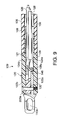
- FIG. 9 is a sectional view of an end portion of a variation of the endoscopic forceps instrument 100 shown in FIGS. 1 through 8.
- first and second rivets 128 a and 128 b are replaced with first and second pins 200 a and 200 b (only first pins 200 a is shown in FIG. 9), which are made from metal such as stainless steel, for example.
- the tip portion of the first and second pins 200 a and 200 b are provided with a thread and screw coupled with the corresponding bore ( 182 , 184 ).
- the variation of the endoscopic forceps instrument shown in FIG. 9 has essentially the same configuration as the endoscopic forceps instrument shown in FIGS. 1 through 8.
- FIG. 10 is an exploded perspective view of the forceps jaw assembly of the endoscopic forceps instrument shown in FIG. 1, in which the first and second pins 200 a and 200 b are used instead of the first and second rivets 128 a and 128 b. Note that the clevis 120 is not shown in FIG. 10 for clarity of the drawing.
- each of the first and second pins 200 a and 200 b has a body 202 , a head 204 having a larger diameter than the body 202 , and a tip portion 206 having a smaller diameter than the body 202 .
- a thread is formed to each of the tip portions 206 .
- the first and second pins are arranged such that the tip portions 206 thereof are coupled to opposite arms ( 122 a, 122 b ) of the clevis 120 , or the heads 204 are coupled at different arms ( 122 a, 122 b ).
- the heads 204 of the pins ( 200 a, 200 b ) prevents the tip portions 206 thereof from disengaging from the arms ( 122 a, 122 b ) as like in the endoscopic forceps instrument shown in FIGS. 1 through 8.
- the insertion portion 104 of forceps instrument 100 configured as above is introduced into a body cavity such as a stomach through an endoscope and the forceps jaw assembly 109 are located in the vicinity of a target portion such as a bleeding portion.
- the operation portion 102 is operated such that the pair of conductive wires 108 is slid forwards within the sheath 106 and swing the first and second jaws 110 a and 110 b to the open position. Then, the jaws 110 a and 110 b are moved by the endoscope such that bleeding portion is located between the jaws 110 a and 110 b.
- the pair of conductive wires 108 are retracted by pulling back the rod portion 114 with respect to the cylindrical portion 112 to move the front portions 140 of the jaws 110 a and 110 b to the closed position and thereby grasping the bleeding portion.
- a high frequency electrical power is supplied from the power supply 200 to the first and second jaws 110 a and 110 b via the conductive wires 108 .
- a high frequency current flows through the bleeding portion placed between the jaws 110 to coagulate the bleeding portion and thereby stop bleeding therefrom.
Abstract
Description
- The present invention relates to an endoscopic forceps instrument having a pair of opposed jaws at the distal end thereof.
- Typical endoscopic forceps instruments having a pair of opposed jaws include, for example, biopsy forceps, grasping forceps, and hemostatic forceps.
- FIG. 1 shows a distal end of a conventional
endoscopic forceps instrument 10. Theendoscopic forceps instrument 10 includes aclevis 12 coupled to the distal end of aflexible sheath 11. A pair ofopposing jaws 14 is pivotably coupled to the distal end of theclevis 12 by arivet 15. Therivet 15 is inserted into thebores 16 formed to the distal end of the clevis, and extends across theslit 13 of theclevis 12. - A pair of control wires (not shown) are inserted through the
sheath 11 and connected to the pair ofjaws 14. The pair ofopposed jaws 14 open and close if the pair of wires is operated back and forth along thesheath 11 from the proximal end of theendoscopic forceps instrument 10. - The
rivet 15 includes abody 15 b, ahead 15 a having larger diameter than abody 15 b, and atip portion 15 c having smaller diameter than thebody 15 b. Thetip portion 15 c is swaged after therivet 15 is inserted into thebores 16 of theclevis 12 to fix therivet 15 to theclevis 12. However, since the mechanical strength of theswaged tip portion 15 c of therivet 15 is relatively low, therivet 15 comes off from theclevis 15, and hence the distal end of the forceps instrument becomes disassembled, when a large force is exerted on theclevis 15 that acts to widen theslit 13 of the clevis. - Thus, there is a need for an endoscopic forceps instrument of which distal end hardly disassemble.
- The invention is advantageous in that an instrument that satisfies the above-mentioned need is provided.
- According to an aspect of the invention, there is provided an endoscopic forceps instrument having an inserting portion to be inserted into a body cavity through an endoscope. The endoscopic forceps instrument includes a clevis, a pair of rod members, and a pair of opposing jaws.
- The clevis is coupled to a distal end of the inserting portion. The pair of rod members are inserted through bores formed to the clevis and thereby coupled to the clevis. Each of the rod members has a head formed at one end thereof and an engaging portion formed at other end thereof. The head is formed in a shape and size that does not allow the head passing through the bores. The engaging portion is engaged with the clevis, e.g., being swaged or screw coupled, to fix the rod member to the clevis. The pair of opposing jaws is pivotably coupled to respective rod members so as to be movable between an open position and a closed position. The pair of rod members is arranged in parallel to each other. Further, the pair of rod members is arranged such that the engaging portions thereof, which may be swaged or screw coupled, for example, and therefore have relatively low mechanical strength, are located at opposite sides of the clevis. In other words, heads of the rod members, which have larger mechanical strength than the engaged portions, are located at opposite sides of the clevis. Thus, firm engagement between the rivets and the clevis are ensured at both sides of the clevis.
- Optionally, the pair of rod members is arranged such that a longitudinal axis of the clevis passes through a space defined between the pair of rivets.
- Optionally, the pair of jaws are made of a conductive material and connected to a pair of wires so that high frequency electric power can be supplied to the pair of jaws. In this case, the endoscopic forceps instrument may further include an insulating block that is supported by the pair of rivets between the pair of jaws to ensure insulation between the jaws.
- According to another aspect of the invention, a forceps jaw assembly is provided that includes a clevis having a base to be coupled to a distal end of an inserting portion of an endoscopic forceps instrument, a pair of rod members inserted through bores formed to the clevis to be coupled to the clevis, and a pair of opposing jaws pivotably coupled to respective rod members so as to be movable between an open position and a closed position. Each of the rod members has a head formed at one end thereof and an engaging portion formed at other end thereof. The head is formed in a shape and size that does not allow the head passing through the bores. The engaging portion are engaged with the clevis to fix the rod member to the clevis. The rod members are arranged in parallel to each other and such that the heads thereof are located at opposite sides of the clevis.
- FIG. 1 shows a distal end of a conventional endoscopic forceps instrument;
- FIG. 2 schematically shows an endoscopic forceps instrument according to an embodiment of the invention connected to a high frequency power supply;
- FIG. 3 is a perspective view of the distal end of the endoscopic forceps instrument shown in FIG. 2;
- FIG. 4 is a partially sectional side view of the distal end of the endoscopic forceps instrument shown in FIG. 2;
- FIG. 5 is a sectional view of the endoscopic forceps instrument shown in FIG. 4 observed from the direction indicated by an arrow A;
- FIG. 6 is an exploded perspective view of a forceps jaw assembly of the endoscopic forceps instrument shown in FIG. 2;
- FIGS. 7A and 7B respectively show a right side view and a rear side view of an insulating block of the endoscopic forceps instrument shown in FIG. 2;
- FIG. 8 is a sectional view of the forceps jaw assembly taken along the line VIII-VIII in FIG. 4;
- FIG. 9 is a sectional view of an end portion of a variation of the endoscopic forceps instrument shown in FIGS. 1 through 8; and
- FIG. 10 is an exploded perspective view of the forceps jaw assembly of the variation of the endoscopic forceps instrument shown in FIG. 1.
- Hereinafter, an embodiment of the invention will be described with reference to the accompanying drawings.
- FIG. 2 schematically shows an
endoscopic forceps instrument 100 according to an embodiment of the invention connected to a highfrequency power supply 200. - The
forceps instrument 100 includes anoperation portion 102 and aninserting portion 104 connected to the distal end of theoperation portion 102. - The
inserting portion 104 is provided in a form and size that allows it to be introduced into a body cavity through a treatment tool inserting channel of an endoscope (not shown). Theinserting portion 104 includes an elongated,flexible sheath 106, and a pair of conductive wires 108 (only one is shown) slidably passed through thesheath 106. Thesheath 106 is made of insulating material such as poly-tetra-fluoro-ethylene (PTFE). In an exemplary embodiment, thesheath 106 is 1 m to 2 m long and has an outer diameter of 2 mm to 3 mm. - A
forceps jaw assembly 109 is mounted to the distal end of theinserting portion 104. Theforceps jaw assembly 109 includes first andsecond jaws conductive wires 108. - The
operation portion 102 includes acylindrical portion 112 and arod portion 114 slidably inserted into thecylindrical portion 112. - The
cylindrical portion 112 has acircumferential groove 112 a at a proximal end thereof. A user of theforceps instrument 100 can hold theoperation portion 112 by pinching it at thegroove 112 a with his index finger and long finger. - The
rod portion 114 has aring 114 a into which the user can insert his thumb to slide therod portion 114 within thecylindrical portion 112 back and forth. - The
rod portion 114 is connected with the pair ofwires 108 in thecylindrical portion 112 such that thewires 108 retract and proceed in thesheath 106 as therod portion 114 is moved back and forth with respect to thecylindrical portion 112. It should be noted that the pair ofwires 108 may be fixed to each other so that they slide integrally within thesheath 106 to move the pair of jaws 110 simultaneously. - The
conductive wires 108 are detachably connected to power supply lines of the highfrequency power supply 200 via a pair ofconnectors 116 provided to the side surface of thecylindrical portion 112. One of theconductive wires 106 is connected to the positive terminal of thepower supply 200 and the other to the negative terminal. - FIG. 3 is a perspective view of the distal end of the
forceps instrument 100 shown in FIG. 2. FIG. 4 is a partially sectional side view of the distal end of theforceps instrument 100 shown in FIG. 2, and FIG. 5 is a sectional view of the distal end of theforceps instrument 100 shown in FIG. 4 observed from the direction indicated by the arrow A. Note that FIGS. 4 and 5 are drawn as a composite view combining cross sectional views at various positions. - The
forceps jaw assembly 109 includes aclevis 120 to which the first andsecond jaws clevis 120 is made of hard insulating material such as rigid plastic and is mounted to the distal end of theflexible sheath 106. - As shown in FIG. 5, the
clevis 120 has a base 121 connected to the distal end of theflexible sheath 106 and first andsecond arms slit 124 therebetween having a constant width. First andsecond rivets - The first and
second rivets slit 124. Further, the first andsecond rivets clevis 120 passes the center of the space defined therebetween. The first andsecond rivets - The first and
second jaws slit 124 of theclevis 120 and pivotably mounted to the first andsecond rivets jaws jaws jaws - As shown in FIG. 4, the rear ends or proximal ends of the
jaws conductive wires 108. Each of theconductive wires 108 is covered with a insulatingtube 126 except theend portion 108 a thereof at which theconductive wire 108 is connected to the corresponding jaw (110 a, 110 b). - An insulating
block 130 is provided in theslit 124 of theclevis 120 to prevent the first andsecond jaws slit 124. The insulatingblock 130 is located between the first andsecond jaws second rivets - FIG. 6 is an exploded perspective view of the
forceps jaw assembly 109. Note that theclevis 120 is not shown in FIG. 6 for clarity of the drawing. - Each of the first and
second jaws portion 140 and an elongated rear (proximal)portion 142. When thejaws clevis 120, thefront portions 140 thereof are located outside of theslit 124 and therear portions 142 thereof are located between the two arms 122. - Two through holes are formed to the
rear portion 142 of each jaw (110 a, 110 b). The first one is a supportinghole 144 provided at substantially the center of each jaw (110 a, 110 b). The other one is aconnection hole 146 formed in the vicinity of the rear end of each jaw (110 a, 110 b). - The
first jaw 110 a is pivotably mounted to theclevis 120 by inserting thefirst rivet 128 a through the supportinghole 144 thereof, while thesecond jaw 110 b is pivotably mounted to theclevis 120 by inserting thesecond rivet 128 b through the supportinghole 144 thereof. - The tip end of each
conductive wire 108, which is exposed from the insulatingtube 126, is passed through the connectinghole 146 and thereby connected with the corresponding jaw (110 a, 110 b). - The
rear portion 142 of each jaw (110 a, 110 b) is slightly bent so that theconductive wires 108 sliding back and forth within thesheath 106 can swing thejaws respective rivets - The
front portion 140 of each jaw (110 a, 110 b) has a cup like shape. Thejaws jaws - The insulating
block 130 is made of ceramic or resin such as poly-tetra-fluoro-ethylene. The insulatingblock 130 has front and rear sides (150, 152) and right and left sides (154, 156). The insulatingblock 130 is located within theslit 124 of theclevis 120 such that the right and left sides (154, 156) face the right and left inner side surfaces 124 a and 124 b of theslit 124, respectively. - First and second through
holes block 130 which are perpendicular to the right and leftsides block 130. The insulatingblock 130 is mounted to theclevis 120 by inserting the first andsecond rivets holes block 130 is supported by two rivets (128 a, 128 b), it does not rotate within theslit 124. - Each of the rivets ( 128 a and 128 b) has a
body 160, ahead 162 having a larger diameter than thebody 160, and atip portion 164 having a smaller diameter than thebody 160. - FIGS. 7A and 7B show the
right side 154 and therear side 152 of the insulatingblock 130, respectively. Further, FIG. 8 is a sectional view of theforceps jaw assembly 109 taken along the line VIII-VIII in FIG. 4. - The
right side 154 of the insulatingblock 130 is provided with afirst protrusion 154 a. Thefirst protrusion 154 a has a substantiallyflat side surface 154 b. Similarly, theleft side 156 of the insulatingblock 130 is provided with asecond protrusion 156 a which also has a substantiallyflat side surface 156 b. The first andsecond protrusions second protrusions block 130, is substantially same as the width of theslit 124. Thus, the side surfaces 154 b and 156 b of the first andsecond protrusions inner side surface slit 124 when the insulatingblock 130 is located in theslit 124. - As shown in FIG. 8, first and
second protrusions second spaces block 130 and the arms 122 of theclevis 120 for receiving the first andsecond jaws - The first and
second jaws second rivets second spaces - The first and
second protrusions second spaces second jaws second jaw second rivets - As can be seen in FIG. 8, the
first protrusion 154 a is formed such that it surrounds thesecond rivet 128 b in the vicinity of thefirst jaw 110 a and thesecond protrusion 156 a is formed such that it surrounds thefirst rivet 128 a in the vicinity of thesecond jaw 110 b. The first and second protrusions configured as above prevent the first andsecond jaws first rivets - As shown in FIG. 8, the
first arm 122 a of theclevis 120 is provided with twobores 180 and 182, and thesecond arm 122 b is also provided with twobores - Each of the
bores 180 and 184 includes a large diameter portion (180 a, 184 a) and a small diameter portion (180 b, 184 b), which have substantially the same diameters as thehead 162 andbody 160 of the rivets (128 a, 128 b), respectively. The other twobores - The
first rivet 128 a is coupled to theclevis 120 by inserting it into thebores 180 and 186 in a direction from right to left in FIG. 8. Similarly, thesecond rivet 128 b is coupled to theclevis 120 by inserting it into thebores first rivet 128 a, i.e. from left to right in FIG. 8. Thehead 162 of thefirst rivet 128 a (thesecond rivet 128 b) inserted into the bore 180 (184) fits into the large diameter portion 180 a (184 a) of the bore 180 (184). A stepped portion formed between the large diameter portion 180 a (184 a) and thesmall diameter portion 180 b (184 b) prevents thehead 162 of thefirst rivet 128 a (thesecond rivet 128 b) from passing through the bore 180 (184). The end portions of therivets rivets clevis 120. - As described above, the first and
second rivets clevis 120 in opposite directions. Thus, the swaged portions of the rivets (128 a, 128 b), which have lower mechanical strength than theheads 162 thereof, are located at different arms (122 a, 122 b) of theclevis 120. - If an external force is exerted on the arms ( 122 a, 122 b) of the
clevis 120 that acts to widen the width of theslit 124, thehead 162 of thefirst rivet 128 a prevents thefirst arm 122 a from bending outwardly and coming disengaged with thetip portion 164 of thesecond rivet 128 b. Similarly, thehead 162 of thesecond rivet 128 b prevents thetip portion 164 of thefirst rivet 128 a from coming off from thesecond arm 122 b of theclevis 120. Thus, theforceps assembly 109 does not disassemble due to an external force. - FIG. 9 is a sectional view of an end portion of a variation of the
endoscopic forceps instrument 100 shown in FIGS. 1 through 8. In the endoscopic forceps instrument shown in FIG. 9, first andsecond rivets second pins first pins 200 a is shown in FIG. 9), which are made from metal such as stainless steel, for example. The tip portion of the first andsecond pins - FIG. 10 is an exploded perspective view of the forceps jaw assembly of the endoscopic forceps instrument shown in FIG. 1, in which the first and
second pins second rivets clevis 120 is not shown in FIG. 10 for clarity of the drawing. - As shown in FIG. 10, each of the first and
second pins body 202, ahead 204 having a larger diameter than thebody 202, and atip portion 206 having a smaller diameter than thebody 202. As mentioned above, a thread is formed to each of thetip portions 206. The first and second pins are arranged such that thetip portions 206 thereof are coupled to opposite arms (122 a, 122 b) of theclevis 120, or theheads 204 are coupled at different arms (122 a, 122 b). Thus, theheads 204 of the pins (200 a, 200 b) prevents thetip portions 206 thereof from disengaging from the arms (122 a, 122 b) as like in the endoscopic forceps instrument shown in FIGS. 1 through 8. - The
insertion portion 104 offorceps instrument 100 configured as above is introduced into a body cavity such as a stomach through an endoscope and theforceps jaw assembly 109 are located in the vicinity of a target portion such as a bleeding portion. - Then, the
operation portion 102 is operated such that the pair ofconductive wires 108 is slid forwards within thesheath 106 and swing the first andsecond jaws jaws jaws - Next, the pair of
conductive wires 108 are retracted by pulling back therod portion 114 with respect to thecylindrical portion 112 to move thefront portions 140 of thejaws - Next, a high frequency electrical power is supplied from the
power supply 200 to the first andsecond jaws conductive wires 108. As a result, a high frequency current flows through the bleeding portion placed between the jaws 110 to coagulate the bleeding portion and thereby stop bleeding therefrom. - The invention has been described in detail with particular reference to an embodiment thereof, but it will be understood that variations and modifications can be effected within the spirit and scope of the invention. For example, although the forceps instrument described above is supplied with high frequency electric power, the invention can be applied also to forceps instruments that do not utilize high frequency electric power.
- The present disclosure relates to the subject matters contained in Japanese Patent Applications No. P2002-106012, filed on Apr. 9, 2002, and No. P2002-278651, filed on Sep. 25, 2002, which are expressly incorporated herein by reference in their entireties.
Claims (12)
Applications Claiming Priority (4)
| Application Number | Priority Date | Filing Date | Title |
|---|---|---|---|
| JP2002106012 | 2002-04-09 | ||
| JP2002-106012 | 2002-04-09 | ||
| JP2002-278651 | 2002-09-25 | ||
| JP2002278651A JP4131011B2 (en) | 2002-04-09 | 2002-09-25 | Endoscopic sputum treatment device |
Publications (2)
| Publication Number | Publication Date |
|---|---|
| US20030191464A1 true US20030191464A1 (en) | 2003-10-09 |
| US6964662B2 US6964662B2 (en) | 2005-11-15 |
Family
ID=28677629
Family Applications (1)
| Application Number | Title | Priority Date | Filing Date |
|---|---|---|---|
| US10/404,559 Expired - Lifetime US6964662B2 (en) | 2002-04-09 | 2003-04-02 | Endoscopic forceps instrument |
Country Status (3)
| Country | Link |
|---|---|
| US (1) | US6964662B2 (en) |
| JP (1) | JP4131011B2 (en) |
| DE (1) | DE10316134B4 (en) |
Cited By (18)
| Publication number | Priority date | Publication date | Assignee | Title |
|---|---|---|---|---|
| US20050049633A1 (en) * | 2003-08-08 | 2005-03-03 | Olympus Corporation | Hemostatic forceps for endoscope |
| US6953430B2 (en) | 2003-03-18 | 2005-10-11 | Pentax Corporation | Pincerlike instrument for endoscope |
| US20080132891A1 (en) * | 2006-12-05 | 2008-06-05 | Ethicon Endo-Surgery, Inc. | Monopolar resection device and method of use |
| WO2009032623A2 (en) * | 2007-08-31 | 2009-03-12 | Ethicon Endo-Surgery, Inc | Electrical albation surgical instruments |
| US20090124852A1 (en) * | 2005-06-30 | 2009-05-14 | Olympus Medical Systems Corp. | Endoscope device |
| US20090264918A1 (en) * | 2003-12-10 | 2009-10-22 | Boston Scientific Scimed, Inc. | Clevis assemblies for medical instruments and methods of manufacture of same |
| US20100016855A1 (en) * | 2008-07-15 | 2010-01-21 | Immersion Corporation | Modular Tool With Signal Feedback |
| US7762960B2 (en) | 2005-05-13 | 2010-07-27 | Boston Scientific Scimed, Inc. | Biopsy forceps assemblies |
| WO2010101897A1 (en) * | 2009-03-02 | 2010-09-10 | Bovie Medical Corporation | Surgical apparatus for tissue sealing and cutting |
| US20100305564A1 (en) * | 2009-06-02 | 2010-12-02 | Bovie Medical Corporation | Surgical jaws for sealing tissue |
| US7871422B2 (en) | 2004-05-24 | 2011-01-18 | Hoya Corporation | Forceps unit for endoscope |
| US7909850B2 (en) | 1999-10-25 | 2011-03-22 | Boston Scientific Scimed, Inc. | Forceps for medical use |
| US7942896B2 (en) | 2003-11-25 | 2011-05-17 | Scimed Life Systems, Inc. | Forceps and collection assembly and related methods of use and manufacture |
| US8083686B2 (en) | 2003-09-10 | 2011-12-27 | Boston Scientific Scimed, Inc. | Forceps and collection assembly with accompanying mechanisms and related methods of use |
| US8469993B2 (en) | 2003-06-18 | 2013-06-25 | Boston Scientific Scimed, Inc. | Endoscopic instruments |
| US8579897B2 (en) * | 2007-11-21 | 2013-11-12 | Ethicon Endo-Surgery, Inc. | Bipolar forceps |
| CN105125278A (en) * | 2014-05-29 | 2015-12-09 | 陆骏 | Combined endoscope surgical instrument |
| US9681857B2 (en) | 2003-06-18 | 2017-06-20 | Boston Scientific Scimed, Inc. | Endoscopic instruments and methods of manufacture |
Families Citing this family (213)
| Publication number | Priority date | Publication date | Assignee | Title |
|---|---|---|---|---|
| US6267761B1 (en) * | 1997-09-09 | 2001-07-31 | Sherwood Services Ag | Apparatus and method for sealing and cutting tissue |
| US6726686B2 (en) | 1997-11-12 | 2004-04-27 | Sherwood Services Ag | Bipolar electrosurgical instrument for sealing vessels |
| US7435249B2 (en) | 1997-11-12 | 2008-10-14 | Covidien Ag | Electrosurgical instruments which reduces collateral damage to adjacent tissue |
| US6228083B1 (en) | 1997-11-14 | 2001-05-08 | Sherwood Services Ag | Laparoscopic bipolar electrosurgical instrument |
| US7364577B2 (en) | 2002-02-11 | 2008-04-29 | Sherwood Services Ag | Vessel sealing system |
| US7118570B2 (en) | 2001-04-06 | 2006-10-10 | Sherwood Services Ag | Vessel sealing forceps with disposable electrodes |
| US7582087B2 (en) | 1998-10-23 | 2009-09-01 | Covidien Ag | Vessel sealing instrument |
| US7267677B2 (en) | 1998-10-23 | 2007-09-11 | Sherwood Services Ag | Vessel sealing instrument |
| US7887535B2 (en) | 1999-10-18 | 2011-02-15 | Covidien Ag | Vessel sealing wave jaw |
| US20030109875A1 (en) | 1999-10-22 | 2003-06-12 | Tetzlaff Philip M. | Open vessel sealing forceps with disposable electrodes |
| US10849681B2 (en) | 2001-04-06 | 2020-12-01 | Covidien Ag | Vessel sealer and divider |
| US7101371B2 (en) | 2001-04-06 | 2006-09-05 | Dycus Sean T | Vessel sealer and divider |
| DE60121229T2 (en) | 2001-04-06 | 2007-05-24 | Sherwood Services Ag | DEVICE FOR SEALING AND SHARING A VESSEL WITH NON-LASTING END STOP |
| EP1527747B1 (en) | 2001-04-06 | 2015-09-30 | Covidien AG | Electrosurgical instrument which reduces collateral damage to adjacent tissue |
| JP5073895B2 (en) | 2001-09-25 | 2012-11-14 | オリンパス株式会社 | Endoscopic treatment tool |
| US7276068B2 (en) | 2002-10-04 | 2007-10-02 | Sherwood Services Ag | Vessel sealing instrument with electrical cutting mechanism |
| US7270664B2 (en) | 2002-10-04 | 2007-09-18 | Sherwood Services Ag | Vessel sealing instrument with electrical cutting mechanism |
| US7931649B2 (en) | 2002-10-04 | 2011-04-26 | Tyco Healthcare Group Lp | Vessel sealing instrument with electrical cutting mechanism |
| US7799026B2 (en) | 2002-11-14 | 2010-09-21 | Covidien Ag | Compressible jaw configuration with bipolar RF output electrodes for soft tissue fusion |
| US7776036B2 (en) | 2003-03-13 | 2010-08-17 | Covidien Ag | Bipolar concentric electrode assembly for soft tissue fusion |
| US20050245789A1 (en) | 2003-04-01 | 2005-11-03 | Boston Scientific Scimed, Inc. | Fluid manifold for endoscope system |
| US7591783B2 (en) | 2003-04-01 | 2009-09-22 | Boston Scientific Scimed, Inc. | Articulation joint for video endoscope |
| US8118732B2 (en) | 2003-04-01 | 2012-02-21 | Boston Scientific Scimed, Inc. | Force feedback control system for video endoscope |
| US20040199052A1 (en) | 2003-04-01 | 2004-10-07 | Scimed Life Systems, Inc. | Endoscopic imaging system |
| US7578786B2 (en) | 2003-04-01 | 2009-08-25 | Boston Scientific Scimed, Inc. | Video endoscope |
| US7160299B2 (en) | 2003-05-01 | 2007-01-09 | Sherwood Services Ag | Method of fusing biomaterials with radiofrequency energy |
| US8128624B2 (en) | 2003-05-01 | 2012-03-06 | Covidien Ag | Electrosurgical instrument that directs energy delivery and protects adjacent tissue |
| CA2523675C (en) | 2003-05-01 | 2016-04-26 | Sherwood Services Ag | Electrosurgical instrument which reduces thermal damage to adjacent tissue |
| AU2004241092B2 (en) | 2003-05-15 | 2009-06-04 | Covidien Ag | Tissue sealer with non-conductive variable stop members and method of sealing tissue |
| USD956973S1 (en) | 2003-06-13 | 2022-07-05 | Covidien Ag | Movable handle for endoscopic vessel sealer and divider |
| US7150749B2 (en) | 2003-06-13 | 2006-12-19 | Sherwood Services Ag | Vessel sealer and divider having elongated knife stroke and safety cutting mechanism |
| US7156846B2 (en) | 2003-06-13 | 2007-01-02 | Sherwood Services Ag | Vessel sealer and divider for use with small trocars and cannulas |
| US7857812B2 (en) | 2003-06-13 | 2010-12-28 | Covidien Ag | Vessel sealer and divider having elongated knife stroke and safety for cutting mechanism |
| US9848938B2 (en) | 2003-11-13 | 2017-12-26 | Covidien Ag | Compressible jaw configuration with bipolar RF output electrodes for soft tissue fusion |
| US7367976B2 (en) | 2003-11-17 | 2008-05-06 | Sherwood Services Ag | Bipolar forceps having monopolar extension |
| US7811283B2 (en) | 2003-11-19 | 2010-10-12 | Covidien Ag | Open vessel sealing instrument with hourglass cutting mechanism and over-ratchet safety |
| US7500975B2 (en) | 2003-11-19 | 2009-03-10 | Covidien Ag | Spring loaded reciprocating tissue cutting mechanism in a forceps-style electrosurgical instrument |
| US7131970B2 (en) | 2003-11-19 | 2006-11-07 | Sherwood Services Ag | Open vessel sealing instrument with cutting mechanism |
| US7442193B2 (en) | 2003-11-20 | 2008-10-28 | Covidien Ag | Electrically conductive/insulative over-shoe for tissue fusion |
| US7780662B2 (en) | 2004-03-02 | 2010-08-24 | Covidien Ag | Vessel sealing system using capacitive RF dielectric heating |
| US7670282B2 (en) | 2004-06-14 | 2010-03-02 | Pneumrx, Inc. | Lung access device |
| US7766891B2 (en) | 2004-07-08 | 2010-08-03 | Pneumrx, Inc. | Lung device with sealing features |
| EP1781182B1 (en) | 2004-07-08 | 2019-11-13 | PneumRx, Inc. | Pleural effusion treatment device |
| US8353091B2 (en) * | 2004-08-02 | 2013-01-15 | Global Pathogen Solutions, Inc. | Stun gun dart active retrieval system |
| US7195631B2 (en) | 2004-09-09 | 2007-03-27 | Sherwood Services Ag | Forceps with spring loaded end effector assembly |
| US7540872B2 (en) | 2004-09-21 | 2009-06-02 | Covidien Ag | Articulating bipolar electrosurgical instrument |
| US7479106B2 (en) | 2004-09-30 | 2009-01-20 | Boston Scientific Scimed, Inc. | Automated control of irrigation and aspiration in a single-use endoscope |
| US8083671B2 (en) | 2004-09-30 | 2011-12-27 | Boston Scientific Scimed, Inc. | Fluid delivery system for use with an endoscope |
| EP1799095A2 (en) | 2004-09-30 | 2007-06-27 | Boston Scientific Scimed, Inc. | Adapter for use with digital imaging medical device |
| US7955332B2 (en) | 2004-10-08 | 2011-06-07 | Covidien Ag | Mechanism for dividing tissue in a hemostat-style instrument |
| US7686827B2 (en) | 2004-10-21 | 2010-03-30 | Covidien Ag | Magnetic closure mechanism for hemostat |
| JP4874259B2 (en) | 2004-11-23 | 2012-02-15 | ヌームアールエックス・インコーポレーテッド | Steerable device for accessing the target site |
| US7909823B2 (en) | 2005-01-14 | 2011-03-22 | Covidien Ag | Open vessel sealing instrument |
| US7686804B2 (en) | 2005-01-14 | 2010-03-30 | Covidien Ag | Vessel sealer and divider with rotating sealer and cutter |
| US8109981B2 (en) | 2005-01-25 | 2012-02-07 | Valam Corporation | Optical therapies and devices |
| US7491202B2 (en) | 2005-03-31 | 2009-02-17 | Covidien Ag | Electrosurgical forceps with slow closure sealing plates and method of sealing tissue |
| US7837685B2 (en) | 2005-07-13 | 2010-11-23 | Covidien Ag | Switch mechanisms for safe activation of energy on an electrosurgical instrument |
| US7628791B2 (en) | 2005-08-19 | 2009-12-08 | Covidien Ag | Single action tissue sealer |
| US7879035B2 (en) | 2005-09-30 | 2011-02-01 | Covidien Ag | Insulating boot for electrosurgical forceps |
| US7846161B2 (en) | 2005-09-30 | 2010-12-07 | Covidien Ag | Insulating boot for electrosurgical forceps |
| US7789878B2 (en) | 2005-09-30 | 2010-09-07 | Covidien Ag | In-line vessel sealer and divider |
| US7922953B2 (en) | 2005-09-30 | 2011-04-12 | Covidien Ag | Method for manufacturing an end effector assembly |
| CA2561034C (en) | 2005-09-30 | 2014-12-09 | Sherwood Services Ag | Flexible endoscopic catheter with an end effector for coagulating and transfecting tissue |
| US7722607B2 (en) | 2005-09-30 | 2010-05-25 | Covidien Ag | In-line vessel sealer and divider |
| US8882766B2 (en) | 2006-01-24 | 2014-11-11 | Covidien Ag | Method and system for controlling delivery of energy to divide tissue |
| US7766910B2 (en) | 2006-01-24 | 2010-08-03 | Tyco Healthcare Group Lp | Vessel sealer and divider for large tissue structures |
| US8241282B2 (en) | 2006-01-24 | 2012-08-14 | Tyco Healthcare Group Lp | Vessel sealing cutting assemblies |
| US8298232B2 (en) | 2006-01-24 | 2012-10-30 | Tyco Healthcare Group Lp | Endoscopic vessel sealer and divider for large tissue structures |
| US8734443B2 (en) | 2006-01-24 | 2014-05-27 | Covidien Lp | Vessel sealer and divider for large tissue structures |
| US20070191839A1 (en) * | 2006-01-27 | 2007-08-16 | Sdgi Holdings, Inc. | Non-locking multi-axial joints in a vertebral implant and methods of use |
| US7833252B2 (en) * | 2006-01-27 | 2010-11-16 | Warsaw Orthopedic, Inc. | Pivoting joints for spinal implants including designed resistance to motion and methods of use |
| US7722652B2 (en) * | 2006-01-27 | 2010-05-25 | Warsaw Orthopedic, Inc. | Pivoting joints for spinal implants including designed resistance to motion and methods of use |
| US8157837B2 (en) | 2006-03-13 | 2012-04-17 | Pneumrx, Inc. | Minimally invasive lung volume reduction device and method |
| US8888800B2 (en) | 2006-03-13 | 2014-11-18 | Pneumrx, Inc. | Lung volume reduction devices, methods, and systems |
| US9402633B2 (en) | 2006-03-13 | 2016-08-02 | Pneumrx, Inc. | Torque alleviating intra-airway lung volume reduction compressive implant structures |
| US7857827B2 (en) | 2006-04-14 | 2010-12-28 | Ethicon Endo-Surgery, Inc. | Endoscopic device |
| US7998167B2 (en) | 2006-04-14 | 2011-08-16 | Ethicon Endo-Surgery, Inc. | End effector and method of manufacture |
| US20070244510A1 (en) | 2006-04-14 | 2007-10-18 | Ethicon Endo-Surgery, Inc. | Endoscopic device |
| US7955255B2 (en) | 2006-04-20 | 2011-06-07 | Boston Scientific Scimed, Inc. | Imaging assembly with transparent distal cap |
| US8202265B2 (en) | 2006-04-20 | 2012-06-19 | Boston Scientific Scimed, Inc. | Multiple lumen assembly for use in endoscopes or other medical devices |
| US7846158B2 (en) | 2006-05-05 | 2010-12-07 | Covidien Ag | Apparatus and method for electrode thermosurgery |
| DE102006028001B4 (en) * | 2006-06-14 | 2009-11-26 | Paul Peschke Gmbh | Surgical grasping forceps |
| US7776037B2 (en) | 2006-07-07 | 2010-08-17 | Covidien Ag | System and method for controlling electrode gap during tissue sealing |
| US7744615B2 (en) | 2006-07-18 | 2010-06-29 | Covidien Ag | Apparatus and method for transecting tissue on a bipolar vessel sealing instrument |
| US8597297B2 (en) | 2006-08-29 | 2013-12-03 | Covidien Ag | Vessel sealing instrument with multiple electrode configurations |
| DE102006040529A1 (en) * | 2006-08-30 | 2008-03-13 | Paul Peschke Gmbh | Surgical grasping forceps |
| US8070746B2 (en) | 2006-10-03 | 2011-12-06 | Tyco Healthcare Group Lp | Radiofrequency fusion of cardiac tissue |
| CA2664111C (en) | 2006-10-06 | 2016-02-16 | Tyco Healthcare Group Lp | Endoscopic vessel sealer and divider having a flexible articulating shaft |
| US8475453B2 (en) | 2006-10-06 | 2013-07-02 | Covidien Lp | Endoscopic vessel sealer and divider having a flexible articulating shaft |
| US7951149B2 (en) | 2006-10-17 | 2011-05-31 | Tyco Healthcare Group Lp | Ablative material for use with tissue treatment device |
| USD649249S1 (en) | 2007-02-15 | 2011-11-22 | Tyco Healthcare Group Lp | End effectors of an elongated dissecting and dividing instrument |
| US7655004B2 (en) | 2007-02-15 | 2010-02-02 | Ethicon Endo-Surgery, Inc. | Electroporation ablation apparatus, system, and method |
| US7815662B2 (en) | 2007-03-08 | 2010-10-19 | Ethicon Endo-Surgery, Inc. | Surgical suture anchors and deployment device |
| US8267935B2 (en) | 2007-04-04 | 2012-09-18 | Tyco Healthcare Group Lp | Electrosurgical instrument reducing current densities at an insulator conductor junction |
| US8075572B2 (en) | 2007-04-26 | 2011-12-13 | Ethicon Endo-Surgery, Inc. | Surgical suturing apparatus |
| US8100922B2 (en) | 2007-04-27 | 2012-01-24 | Ethicon Endo-Surgery, Inc. | Curved needle suturing tool |
| US20090036881A1 (en) * | 2007-07-30 | 2009-02-05 | Ryan Artale | Polyp removal jaws and method of use |
| US8568410B2 (en) | 2007-08-31 | 2013-10-29 | Ethicon Endo-Surgery, Inc. | Electrical ablation surgical instruments |
| US8262655B2 (en) | 2007-11-21 | 2012-09-11 | Ethicon Endo-Surgery, Inc. | Bipolar forceps |
| US7877853B2 (en) | 2007-09-20 | 2011-02-01 | Tyco Healthcare Group Lp | Method of manufacturing end effector assembly for sealing tissue |
| US7877852B2 (en) | 2007-09-20 | 2011-02-01 | Tyco Healthcare Group Lp | Method of manufacturing an end effector assembly for sealing tissue |
| US8241283B2 (en) | 2007-09-28 | 2012-08-14 | Tyco Healthcare Group Lp | Dual durometer insulating boot for electrosurgical forceps |
| US8221416B2 (en) | 2007-09-28 | 2012-07-17 | Tyco Healthcare Group Lp | Insulating boot for electrosurgical forceps with thermoplastic clevis |
| US8235993B2 (en) | 2007-09-28 | 2012-08-07 | Tyco Healthcare Group Lp | Insulating boot for electrosurgical forceps with exohinged structure |
| US20090088745A1 (en) * | 2007-09-28 | 2009-04-02 | Tyco Healthcare Group Lp | Tapered Insulating Boot for Electrosurgical Forceps |
| US8235992B2 (en) | 2007-09-28 | 2012-08-07 | Tyco Healthcare Group Lp | Insulating boot with mechanical reinforcement for electrosurgical forceps |
| US8267936B2 (en) | 2007-09-28 | 2012-09-18 | Tyco Healthcare Group Lp | Insulating mechanically-interfaced adhesive for electrosurgical forceps |
| US8251996B2 (en) | 2007-09-28 | 2012-08-28 | Tyco Healthcare Group Lp | Insulating sheath for electrosurgical forceps |
| US8236025B2 (en) | 2007-09-28 | 2012-08-07 | Tyco Healthcare Group Lp | Silicone insulated electrosurgical forceps |
| US9023043B2 (en) * | 2007-09-28 | 2015-05-05 | Covidien Lp | Insulating mechanically-interfaced boot and jaws for electrosurgical forceps |
| US20090112059A1 (en) | 2007-10-31 | 2009-04-30 | Nobis Rudolph H | Apparatus and methods for closing a gastrotomy |
| US8480657B2 (en) | 2007-10-31 | 2013-07-09 | Ethicon Endo-Surgery, Inc. | Detachable distal overtube section and methods for forming a sealable opening in the wall of an organ |
| US8764748B2 (en) | 2008-02-06 | 2014-07-01 | Covidien Lp | End effector assembly for electrosurgical device and method for making the same |
| US8623276B2 (en) | 2008-02-15 | 2014-01-07 | Covidien Lp | Method and system for sterilizing an electrosurgical instrument |
| US8262680B2 (en) | 2008-03-10 | 2012-09-11 | Ethicon Endo-Surgery, Inc. | Anastomotic device |
| US8771260B2 (en) | 2008-05-30 | 2014-07-08 | Ethicon Endo-Surgery, Inc. | Actuating and articulating surgical device |
| US8070759B2 (en) | 2008-05-30 | 2011-12-06 | Ethicon Endo-Surgery, Inc. | Surgical fastening device |
| US8652150B2 (en) | 2008-05-30 | 2014-02-18 | Ethicon Endo-Surgery, Inc. | Multifunction surgical device |
| US8114072B2 (en) | 2008-05-30 | 2012-02-14 | Ethicon Endo-Surgery, Inc. | Electrical ablation device |
| US8679003B2 (en) | 2008-05-30 | 2014-03-25 | Ethicon Endo-Surgery, Inc. | Surgical device and endoscope including same |
| US8317806B2 (en) | 2008-05-30 | 2012-11-27 | Ethicon Endo-Surgery, Inc. | Endoscopic suturing tension controlling and indication devices |
| US8906035B2 (en) | 2008-06-04 | 2014-12-09 | Ethicon Endo-Surgery, Inc. | Endoscopic drop off bag |
| US8403926B2 (en) | 2008-06-05 | 2013-03-26 | Ethicon Endo-Surgery, Inc. | Manually articulating devices |
| US8361112B2 (en) | 2008-06-27 | 2013-01-29 | Ethicon Endo-Surgery, Inc. | Surgical suture arrangement |
| US8888792B2 (en) | 2008-07-14 | 2014-11-18 | Ethicon Endo-Surgery, Inc. | Tissue apposition clip application devices and methods |
| US8262563B2 (en) | 2008-07-14 | 2012-09-11 | Ethicon Endo-Surgery, Inc. | Endoscopic translumenal articulatable steerable overtube |
| US9204923B2 (en) | 2008-07-16 | 2015-12-08 | Intuitive Surgical Operations, Inc. | Medical instrument electronically energized using drive cables |
| US8469956B2 (en) | 2008-07-21 | 2013-06-25 | Covidien Lp | Variable resistor jaw |
| US8257387B2 (en) | 2008-08-15 | 2012-09-04 | Tyco Healthcare Group Lp | Method of transferring pressure in an articulating surgical instrument |
| US8211125B2 (en) | 2008-08-15 | 2012-07-03 | Ethicon Endo-Surgery, Inc. | Sterile appliance delivery device for endoscopic procedures |
| US8162973B2 (en) | 2008-08-15 | 2012-04-24 | Tyco Healthcare Group Lp | Method of transferring pressure in an articulating surgical instrument |
| US9603652B2 (en) | 2008-08-21 | 2017-03-28 | Covidien Lp | Electrosurgical instrument including a sensor |
| US8529563B2 (en) | 2008-08-25 | 2013-09-10 | Ethicon Endo-Surgery, Inc. | Electrical ablation devices |
| US8317787B2 (en) | 2008-08-28 | 2012-11-27 | Covidien Lp | Tissue fusion jaw angle improvement |
| US8795274B2 (en) | 2008-08-28 | 2014-08-05 | Covidien Lp | Tissue fusion jaw angle improvement |
| US8784417B2 (en) | 2008-08-28 | 2014-07-22 | Covidien Lp | Tissue fusion jaw angle improvement |
| US8241204B2 (en) | 2008-08-29 | 2012-08-14 | Ethicon Endo-Surgery, Inc. | Articulating end cap |
| US8480689B2 (en) | 2008-09-02 | 2013-07-09 | Ethicon Endo-Surgery, Inc. | Suturing device |
| US8409200B2 (en) | 2008-09-03 | 2013-04-02 | Ethicon Endo-Surgery, Inc. | Surgical grasping device |
| US8114119B2 (en) | 2008-09-09 | 2012-02-14 | Ethicon Endo-Surgery, Inc. | Surgical grasping device |
| US9173669B2 (en) | 2008-09-12 | 2015-11-03 | Pneumrx, Inc. | Enhanced efficacy lung volume reduction devices, methods, and systems |
| US8303582B2 (en) | 2008-09-15 | 2012-11-06 | Tyco Healthcare Group Lp | Electrosurgical instrument having a coated electrode utilizing an atomic layer deposition technique |
| US8535312B2 (en) | 2008-09-25 | 2013-09-17 | Covidien Lp | Apparatus, system and method for performing an electrosurgical procedure |
| US9375254B2 (en) | 2008-09-25 | 2016-06-28 | Covidien Lp | Seal and separate algorithm |
| US8968314B2 (en) | 2008-09-25 | 2015-03-03 | Covidien Lp | Apparatus, system and method for performing an electrosurgical procedure |
| US8337394B2 (en) | 2008-10-01 | 2012-12-25 | Ethicon Endo-Surgery, Inc. | Overtube with expandable tip |
| US8142473B2 (en) | 2008-10-03 | 2012-03-27 | Tyco Healthcare Group Lp | Method of transferring rotational motion in an articulating surgical instrument |
| US8469957B2 (en) | 2008-10-07 | 2013-06-25 | Covidien Lp | Apparatus, system, and method for performing an electrosurgical procedure |
| US8636761B2 (en) | 2008-10-09 | 2014-01-28 | Covidien Lp | Apparatus, system, and method for performing an endoscopic electrosurgical procedure |
| US8016827B2 (en) | 2008-10-09 | 2011-09-13 | Tyco Healthcare Group Lp | Apparatus, system, and method for performing an electrosurgical procedure |
| US8486107B2 (en) | 2008-10-20 | 2013-07-16 | Covidien Lp | Method of sealing tissue using radiofrequency energy |
| US8157834B2 (en) | 2008-11-25 | 2012-04-17 | Ethicon Endo-Surgery, Inc. | Rotational coupling device for surgical instrument with flexible actuators |
| US8197479B2 (en) | 2008-12-10 | 2012-06-12 | Tyco Healthcare Group Lp | Vessel sealer and divider |
| US8172772B2 (en) | 2008-12-11 | 2012-05-08 | Ethicon Endo-Surgery, Inc. | Specimen retrieval device |
| US8828031B2 (en) | 2009-01-12 | 2014-09-09 | Ethicon Endo-Surgery, Inc. | Apparatus for forming an anastomosis |
| US8361066B2 (en) | 2009-01-12 | 2013-01-29 | Ethicon Endo-Surgery, Inc. | Electrical ablation devices |
| US8114122B2 (en) | 2009-01-13 | 2012-02-14 | Tyco Healthcare Group Lp | Apparatus, system, and method for performing an electrosurgical procedure |
| US8252057B2 (en) | 2009-01-30 | 2012-08-28 | Ethicon Endo-Surgery, Inc. | Surgical access device |
| US9226772B2 (en) | 2009-01-30 | 2016-01-05 | Ethicon Endo-Surgery, Inc. | Surgical device |
| US8037591B2 (en) | 2009-02-02 | 2011-10-18 | Ethicon Endo-Surgery, Inc. | Surgical scissors |
| WO2010104755A1 (en) * | 2009-03-05 | 2010-09-16 | Tyco Healthcare Group Lp | Endoscopic vessel sealer and divider having a flexible articulating shaft |
| US8187273B2 (en) | 2009-05-07 | 2012-05-29 | Tyco Healthcare Group Lp | Apparatus, system, and method for performing an electrosurgical procedure |
| CN104622599B (en) | 2009-05-18 | 2017-04-12 | 纽姆克斯股份有限公司 | Cross-sectional modification during deployment of an elongate lung volume reduction device |
| US8246618B2 (en) | 2009-07-08 | 2012-08-21 | Tyco Healthcare Group Lp | Electrosurgical jaws with offset knife |
| US8382791B2 (en) * | 2009-08-28 | 2013-02-26 | The Penn State Research Foundation | Surgical tool |
| US8133254B2 (en) | 2009-09-18 | 2012-03-13 | Tyco Healthcare Group Lp | In vivo attachable and detachable end effector assembly and laparoscopic surgical instrument and methods therefor |
| US8112871B2 (en) | 2009-09-28 | 2012-02-14 | Tyco Healthcare Group Lp | Method for manufacturing electrosurgical seal plates |
| US20110098704A1 (en) | 2009-10-28 | 2011-04-28 | Ethicon Endo-Surgery, Inc. | Electrical ablation devices |
| US8608652B2 (en) | 2009-11-05 | 2013-12-17 | Ethicon Endo-Surgery, Inc. | Vaginal entry surgical devices, kit, system, and method |
| US8353487B2 (en) | 2009-12-17 | 2013-01-15 | Ethicon Endo-Surgery, Inc. | User interface support devices for endoscopic surgical instruments |
| US8496574B2 (en) | 2009-12-17 | 2013-07-30 | Ethicon Endo-Surgery, Inc. | Selectively positionable camera for surgical guide tube assembly |
| US8506564B2 (en) | 2009-12-18 | 2013-08-13 | Ethicon Endo-Surgery, Inc. | Surgical instrument comprising an electrode |
| US9028483B2 (en) | 2009-12-18 | 2015-05-12 | Ethicon Endo-Surgery, Inc. | Surgical instrument comprising an electrode |
| US9005198B2 (en) | 2010-01-29 | 2015-04-14 | Ethicon Endo-Surgery, Inc. | Surgical instrument comprising an electrode |
| US9339341B2 (en) * | 2010-02-08 | 2016-05-17 | Intuitive Surgical Operations, Inc. | Direct pull surgical gripper |
| JP4933684B2 (en) * | 2010-05-31 | 2012-05-16 | オリンパスメディカルシステムズ株式会社 | Endoscopic treatment tool |
| USD670808S1 (en) | 2010-10-01 | 2012-11-13 | Tyco Healthcare Group Lp | Open vessel sealing forceps |
| US9345534B2 (en) | 2010-10-04 | 2016-05-24 | Covidien Lp | Vessel sealing instrument |
| US9655672B2 (en) | 2010-10-04 | 2017-05-23 | Covidien Lp | Vessel sealing instrument |
| US9113940B2 (en) | 2011-01-14 | 2015-08-25 | Covidien Lp | Trigger lockout and kickback mechanism for surgical instruments |
| US10092291B2 (en) | 2011-01-25 | 2018-10-09 | Ethicon Endo-Surgery, Inc. | Surgical instrument with selectively rigidizable features |
| US9233241B2 (en) | 2011-02-28 | 2016-01-12 | Ethicon Endo-Surgery, Inc. | Electrical ablation devices and methods |
| US9314620B2 (en) | 2011-02-28 | 2016-04-19 | Ethicon Endo-Surgery, Inc. | Electrical ablation devices and methods |
| US9254169B2 (en) | 2011-02-28 | 2016-02-09 | Ethicon Endo-Surgery, Inc. | Electrical ablation devices and methods |
| US9049987B2 (en) | 2011-03-17 | 2015-06-09 | Ethicon Endo-Surgery, Inc. | Hand held surgical device for manipulating an internal magnet assembly within a patient |
| US9060780B2 (en) * | 2011-09-29 | 2015-06-23 | Covidien Lp | Methods of manufacturing shafts for surgical instruments |
| USD680220S1 (en) | 2012-01-12 | 2013-04-16 | Coviden IP | Slider handle for laparoscopic device |
| US8986199B2 (en) | 2012-02-17 | 2015-03-24 | Ethicon Endo-Surgery, Inc. | Apparatus and methods for cleaning the lens of an endoscope |
| WO2013152019A1 (en) | 2012-04-02 | 2013-10-10 | Nutech Ventures | Compliant surgical graspers and methods of making and using |
| US9427255B2 (en) | 2012-05-14 | 2016-08-30 | Ethicon Endo-Surgery, Inc. | Apparatus for introducing a steerable camera assembly into a patient |
| US9078662B2 (en) | 2012-07-03 | 2015-07-14 | Ethicon Endo-Surgery, Inc. | Endoscopic cap electrode and method for using the same |
| US9545290B2 (en) | 2012-07-30 | 2017-01-17 | Ethicon Endo-Surgery, Inc. | Needle probe guide |
| US10314649B2 (en) | 2012-08-02 | 2019-06-11 | Ethicon Endo-Surgery, Inc. | Flexible expandable electrode and method of intraluminal delivery of pulsed power |
| US9572623B2 (en) | 2012-08-02 | 2017-02-21 | Ethicon Endo-Surgery, Inc. | Reusable electrode and disposable sheath |
| US9277957B2 (en) | 2012-08-15 | 2016-03-08 | Ethicon Endo-Surgery, Inc. | Electrosurgical devices and methods |
| US9265566B2 (en) | 2012-10-16 | 2016-02-23 | Covidien Lp | Surgical instrument |
| US9433462B2 (en) | 2012-12-21 | 2016-09-06 | Cook Medical Technologies Llc | Tissue fusion system, apparatus and method |
| US10098527B2 (en) | 2013-02-27 | 2018-10-16 | Ethidcon Endo-Surgery, Inc. | System for performing a minimally invasive surgical procedure |
| US10646267B2 (en) | 2013-08-07 | 2020-05-12 | Covidien LLP | Surgical forceps |
| USD788302S1 (en) | 2013-10-01 | 2017-05-30 | Covidien Lp | Knife for endoscopic electrosurgical forceps |
| US10390838B1 (en) | 2014-08-20 | 2019-08-27 | Pneumrx, Inc. | Tuned strength chronic obstructive pulmonary disease treatment |
| US10231777B2 (en) | 2014-08-26 | 2019-03-19 | Covidien Lp | Methods of manufacturing jaw members of an end-effector assembly for a surgical instrument |
| JP1527556S (en) * | 2014-10-30 | 2015-06-29 | ||
| JP1527839S (en) * | 2014-10-30 | 2015-06-29 | ||
| US9987078B2 (en) | 2015-07-22 | 2018-06-05 | Covidien Lp | Surgical forceps |
| WO2017031712A1 (en) | 2015-08-26 | 2017-03-02 | Covidien Lp | Electrosurgical end effector assemblies and electrosurgical forceps configured to reduce thermal spread |
| US10213250B2 (en) | 2015-11-05 | 2019-02-26 | Covidien Lp | Deployment and safety mechanisms for surgical instruments |
| US10856933B2 (en) | 2016-08-02 | 2020-12-08 | Covidien Lp | Surgical instrument housing incorporating a channel and methods of manufacturing the same |
| US10918407B2 (en) | 2016-11-08 | 2021-02-16 | Covidien Lp | Surgical instrument for grasping, treating, and/or dividing tissue |
| US10792060B2 (en) | 2017-03-14 | 2020-10-06 | Gyrus Acmi, Inc. | Instrument with a controlled jaw movement |
| CA3060663C (en) | 2017-04-28 | 2024-03-26 | Edwards Lifesciences Corporation | Prosthetic heart valve with collapsible holder |
| US11166759B2 (en) | 2017-05-16 | 2021-11-09 | Covidien Lp | Surgical forceps |
| US11291514B2 (en) | 2018-11-15 | 2022-04-05 | Intuitive Surgical Operations, Inc. | Medical devices having multiple blades and methods of use |
Citations (11)
| Publication number | Priority date | Publication date | Assignee | Title |
|---|---|---|---|---|
| US123667A (en) * | 1872-02-13 | Improvement in machines for cutting out and flanging metallic disks | ||
| US5035248A (en) * | 1987-04-23 | 1991-07-30 | Zinnecker Hal P | Polyolefin sheath and silicone O-ring for medical instrument |
| US5330471A (en) * | 1991-06-07 | 1994-07-19 | Hemostatic Surgery Corporation | Bi-polar electrosurgical endoscopic instruments and methods of use |
| US5762613A (en) * | 1996-05-07 | 1998-06-09 | Spectrascience, Inc. | Optical biopsy forceps |
| US5843000A (en) * | 1996-05-07 | 1998-12-01 | The General Hospital Corporation | Optical biopsy forceps and method of diagnosing tissue |
| US5906630A (en) * | 1998-06-30 | 1999-05-25 | Boston Scientific Limited | Eccentric surgical forceps |
| US6063103A (en) * | 1998-07-24 | 2000-05-16 | Olympus Optical Co., Ltd. | Endoscope forceps |
| US6066102A (en) * | 1998-03-09 | 2000-05-23 | Spectrascience, Inc. | Optical biopsy forceps system and method of diagnosing tissue |
| US6083240A (en) * | 1997-01-29 | 2000-07-04 | Asahi Kogaku Kogyo Kabushiki Kaisha | Link mechanism unit included in a link mechanism for an endoscopic forceps |
| US20010021859A1 (en) * | 2000-02-24 | 2001-09-13 | Toshikazu Kawai | Forceps and manipulator with using thereof |
| US6887240B1 (en) * | 1995-09-19 | 2005-05-03 | Sherwood Services Ag | Vessel sealing wave jaw |
Family Cites Families (5)
| Publication number | Priority date | Publication date | Assignee | Title |
|---|---|---|---|---|
| JPS61263443A (en) | 1985-05-16 | 1986-11-21 | オリンパス光学工業株式会社 | Forcept apparatus for endoscope |
| JPH08140987A (en) | 1994-11-21 | 1996-06-04 | Olympus Optical Co Ltd | Forceps assembling jig for endoscope |
| DE19608716C1 (en) * | 1996-03-06 | 1997-04-17 | Aesculap Ag | Bipolar surgical holding instrument |
| JP2000271128A (en) * | 1999-03-29 | 2000-10-03 | Asahi Optical Co Ltd | High frequency biopsy forceps for endoscope |
| JP4295925B2 (en) | 2001-03-01 | 2009-07-15 | Hoya株式会社 | Bipolar high-frequency treatment instrument for endoscope |
-
2002
- 2002-09-25 JP JP2002278651A patent/JP4131011B2/en not_active Expired - Lifetime
-
2003
- 2003-04-02 US US10/404,559 patent/US6964662B2/en not_active Expired - Lifetime
- 2003-04-09 DE DE10316134A patent/DE10316134B4/en not_active Expired - Lifetime
Patent Citations (12)
| Publication number | Priority date | Publication date | Assignee | Title |
|---|---|---|---|---|
| US123667A (en) * | 1872-02-13 | Improvement in machines for cutting out and flanging metallic disks | ||
| US5035248A (en) * | 1987-04-23 | 1991-07-30 | Zinnecker Hal P | Polyolefin sheath and silicone O-ring for medical instrument |
| US5330471A (en) * | 1991-06-07 | 1994-07-19 | Hemostatic Surgery Corporation | Bi-polar electrosurgical endoscopic instruments and methods of use |
| US6887240B1 (en) * | 1995-09-19 | 2005-05-03 | Sherwood Services Ag | Vessel sealing wave jaw |
| US5762613A (en) * | 1996-05-07 | 1998-06-09 | Spectrascience, Inc. | Optical biopsy forceps |
| US5843000A (en) * | 1996-05-07 | 1998-12-01 | The General Hospital Corporation | Optical biopsy forceps and method of diagnosing tissue |
| US6129683A (en) * | 1996-05-07 | 2000-10-10 | Spectrascience, Inc. | Optical biopsy forceps |
| US6083240A (en) * | 1997-01-29 | 2000-07-04 | Asahi Kogaku Kogyo Kabushiki Kaisha | Link mechanism unit included in a link mechanism for an endoscopic forceps |
| US6066102A (en) * | 1998-03-09 | 2000-05-23 | Spectrascience, Inc. | Optical biopsy forceps system and method of diagnosing tissue |
| US5906630A (en) * | 1998-06-30 | 1999-05-25 | Boston Scientific Limited | Eccentric surgical forceps |
| US6063103A (en) * | 1998-07-24 | 2000-05-16 | Olympus Optical Co., Ltd. | Endoscope forceps |
| US20010021859A1 (en) * | 2000-02-24 | 2001-09-13 | Toshikazu Kawai | Forceps and manipulator with using thereof |
Cited By (28)
| Publication number | Priority date | Publication date | Assignee | Title |
|---|---|---|---|---|
| US7909850B2 (en) | 1999-10-25 | 2011-03-22 | Boston Scientific Scimed, Inc. | Forceps for medical use |
| US6953430B2 (en) | 2003-03-18 | 2005-10-11 | Pentax Corporation | Pincerlike instrument for endoscope |
| US9681857B2 (en) | 2003-06-18 | 2017-06-20 | Boston Scientific Scimed, Inc. | Endoscopic instruments and methods of manufacture |
| US8469993B2 (en) | 2003-06-18 | 2013-06-25 | Boston Scientific Scimed, Inc. | Endoscopic instruments |
| US20050049633A1 (en) * | 2003-08-08 | 2005-03-03 | Olympus Corporation | Hemostatic forceps for endoscope |
| US7736363B2 (en) * | 2003-08-08 | 2010-06-15 | Olympus Corporation | Hemostatic forceps for endoscope |
| US8460205B2 (en) | 2003-09-10 | 2013-06-11 | Boston Scientific Scimed, Inc. | Forceps and collection assembly with accompanying mechanisms and related methods of use |
| US8083686B2 (en) | 2003-09-10 | 2011-12-27 | Boston Scientific Scimed, Inc. | Forceps and collection assembly with accompanying mechanisms and related methods of use |
| US7942896B2 (en) | 2003-11-25 | 2011-05-17 | Scimed Life Systems, Inc. | Forceps and collection assembly and related methods of use and manufacture |
| US20090264918A1 (en) * | 2003-12-10 | 2009-10-22 | Boston Scientific Scimed, Inc. | Clevis assemblies for medical instruments and methods of manufacture of same |
| US7871422B2 (en) | 2004-05-24 | 2011-01-18 | Hoya Corporation | Forceps unit for endoscope |
| US8672859B2 (en) | 2005-05-13 | 2014-03-18 | Boston Scientific Scimed, Inc. | Biopsy forceps assemblies |
| US7762960B2 (en) | 2005-05-13 | 2010-07-27 | Boston Scientific Scimed, Inc. | Biopsy forceps assemblies |
| US8317726B2 (en) | 2005-05-13 | 2012-11-27 | Boston Scientific Scimed, Inc. | Biopsy forceps assemblies |
| US20090124852A1 (en) * | 2005-06-30 | 2009-05-14 | Olympus Medical Systems Corp. | Endoscope device |
| US20080132891A1 (en) * | 2006-12-05 | 2008-06-05 | Ethicon Endo-Surgery, Inc. | Monopolar resection device and method of use |
| US7758577B2 (en) * | 2006-12-05 | 2010-07-20 | Ethicon Endo-Surgery, Inc. | Monopolar resection device and method of use |
| WO2009032623A2 (en) * | 2007-08-31 | 2009-03-12 | Ethicon Endo-Surgery, Inc | Electrical albation surgical instruments |
| WO2009032623A3 (en) * | 2007-08-31 | 2009-07-23 | Ethicon Endo Surgery Inc | Electrical albation surgical instruments |
| US8579897B2 (en) * | 2007-11-21 | 2013-11-12 | Ethicon Endo-Surgery, Inc. | Bipolar forceps |
| US8834465B2 (en) * | 2008-07-15 | 2014-09-16 | Immersion Corporation | Modular tool with signal feedback |
| US20100016855A1 (en) * | 2008-07-15 | 2010-01-21 | Immersion Corporation | Modular Tool With Signal Feedback |
| US20100292690A1 (en) * | 2009-03-02 | 2010-11-18 | Bovie Medical Corporation | Surgical apparatus for tissue sealing and cutting |
| US8647342B2 (en) | 2009-03-02 | 2014-02-11 | Bovie Medical Corporation | Surgical apparatus for tissue sealing and cutting |
| WO2010101897A1 (en) * | 2009-03-02 | 2010-09-10 | Bovie Medical Corporation | Surgical apparatus for tissue sealing and cutting |
| US20100305564A1 (en) * | 2009-06-02 | 2010-12-02 | Bovie Medical Corporation | Surgical jaws for sealing tissue |
| US9572621B2 (en) | 2009-06-02 | 2017-02-21 | Bovie Medical Corporation | Surgical jaws for sealing tissue |
| CN105125278A (en) * | 2014-05-29 | 2015-12-09 | 陆骏 | Combined endoscope surgical instrument |
Also Published As
| Publication number | Publication date |
|---|---|
| DE10316134A1 (en) | 2003-10-30 |
| JP2004000424A (en) | 2004-01-08 |
| US6964662B2 (en) | 2005-11-15 |
| DE10316134B4 (en) | 2008-11-27 |
| JP4131011B2 (en) | 2008-08-13 |
Similar Documents
| Publication | Publication Date | Title |
|---|---|---|
| US6964662B2 (en) | Endoscopic forceps instrument | |
| US6969389B2 (en) | Bipolar hemostatic forceps for an endoscope | |
| US10870143B2 (en) | Connection structure and connection method | |
| US7326209B2 (en) | Bipolar high frequency treatment tool for endoscope | |
| KR102257277B1 (en) | Bipolar cautery instrument | |
| KR101055526B1 (en) | Surgical surgical device | |
| US7276066B2 (en) | Medical instrument for endoscope | |
| US6953430B2 (en) | Pincerlike instrument for endoscope | |
| US8177804B2 (en) | Surgical instrument | |
| US7824407B2 (en) | Treatment tool for endoscope | |
| US8795273B2 (en) | Treatment tool for endoscope | |
| US6458124B1 (en) | Electrosurgical handle for bipolar/unipolar electrodes | |
| US20060178669A1 (en) | High-frequency treatment tool for endoscope | |
| JP2001046393A (en) | Operation wire connecting part for treatment implement of endoscope | |
| WO2004108001A1 (en) | Medical treatment tool and medical treatment equipment comprising it | |
| US20030191465A1 (en) | Electrosurgicalscissors for endoscopic mucosal resection | |
| US20090264918A1 (en) | Clevis assemblies for medical instruments and methods of manufacture of same | |
| US7354439B2 (en) | Treatment tool for endoscope having end effector operating like pincers | |
| US6951560B1 (en) | Bipolar high frequency treatment tool for an endoscope | |
| JP5290658B2 (en) | Endoscopic treatment tool | |
| US20220022956A1 (en) | Endoscope snare | |
| US20070088353A1 (en) | High-frequency incision instrument for endoscope | |
| JP2010142279A (en) | Treatment instrument | |
| US7967819B2 (en) | Soft bipolar forceps | |
| JP2010035695A (en) | Treatment tool for endoscope |
Legal Events
| Date | Code | Title | Description |
|---|---|---|---|
| AS | Assignment |
Owner name: PENTAX CORPORATION, JAPAN Free format text: ASSIGNMENT OF ASSIGNORS INTEREST;ASSIGNOR:KIDOOKA, SATOSHI;REEL/FRAME:013932/0640 Effective date: 20030327 |
|
| STCF | Information on status: patent grant |
Free format text: PATENTED CASE |
|
| FEPP | Fee payment procedure |
Free format text: PAYOR NUMBER ASSIGNED (ORIGINAL EVENT CODE: ASPN); ENTITY STATUS OF PATENT OWNER: LARGE ENTITY |
|
| FPAY | Fee payment |
Year of fee payment: 4 |
|
| FPAY | Fee payment |
Year of fee payment: 8 |
|
| AS | Assignment |
Owner name: HOYA CORPORATION, JAPAN Free format text: MERGER;ASSIGNOR:PENTAX CORPORATION;REEL/FRAME:042114/0463 Effective date: 20080407 |
|
| FPAY | Fee payment |
Year of fee payment: 12 |
|
| AS | Assignment |
Owner name: HOYA CORPORATION, JAPAN Free format text: CHANGE OF ADDRESS OF ASSIGNEE;ASSIGNOR:HOYA CORPORATION;REEL/FRAME:042424/0318 Effective date: 20160401 |