US20030191494A1 - Surgical device with malleable shaft - Google Patents
Surgical device with malleable shaft Download PDFInfo
- Publication number
- US20030191494A1 US20030191494A1 US10/412,044 US41204403A US2003191494A1 US 20030191494 A1 US20030191494 A1 US 20030191494A1 US 41204403 A US41204403 A US 41204403A US 2003191494 A1 US2003191494 A1 US 2003191494A1
- Authority
- US
- United States
- Prior art keywords
- tissue engaging
- surgical device
- engaging means
- shaft member
- jaws
- Prior art date
- Legal status (The legal status is an assumption and is not a legal conclusion. Google has not performed a legal analysis and makes no representation as to the accuracy of the status listed.)
- Abandoned
Links
Images


Classifications
-
- A—HUMAN NECESSITIES
- A61—MEDICAL OR VETERINARY SCIENCE; HYGIENE
- A61B—DIAGNOSIS; SURGERY; IDENTIFICATION
- A61B17/00—Surgical instruments, devices or methods, e.g. tourniquets
- A61B17/12—Surgical instruments, devices or methods, e.g. tourniquets for ligaturing or otherwise compressing tubular parts of the body, e.g. blood vessels, umbilical cord
- A61B17/128—Surgical instruments, devices or methods, e.g. tourniquets for ligaturing or otherwise compressing tubular parts of the body, e.g. blood vessels, umbilical cord for applying or removing clamps or clips
- A61B17/1285—Surgical instruments, devices or methods, e.g. tourniquets for ligaturing or otherwise compressing tubular parts of the body, e.g. blood vessels, umbilical cord for applying or removing clamps or clips for minimally invasive surgery
-
- A—HUMAN NECESSITIES
- A61—MEDICAL OR VETERINARY SCIENCE; HYGIENE
- A61B—DIAGNOSIS; SURGERY; IDENTIFICATION
- A61B17/00—Surgical instruments, devices or methods, e.g. tourniquets
- A61B17/12—Surgical instruments, devices or methods, e.g. tourniquets for ligaturing or otherwise compressing tubular parts of the body, e.g. blood vessels, umbilical cord
- A61B17/122—Clamps or clips, e.g. for the umbilical cord
-
- A—HUMAN NECESSITIES
- A61—MEDICAL OR VETERINARY SCIENCE; HYGIENE
- A61B—DIAGNOSIS; SURGERY; IDENTIFICATION
- A61B17/00—Surgical instruments, devices or methods, e.g. tourniquets
- A61B17/28—Surgical forceps
- A61B17/29—Forceps for use in minimally invasive surgery
-
- A—HUMAN NECESSITIES
- A61—MEDICAL OR VETERINARY SCIENCE; HYGIENE
- A61B—DIAGNOSIS; SURGERY; IDENTIFICATION
- A61B17/00—Surgical instruments, devices or methods, e.g. tourniquets
- A61B2017/0023—Surgical instruments, devices or methods, e.g. tourniquets disposable
-
- A—HUMAN NECESSITIES
- A61—MEDICAL OR VETERINARY SCIENCE; HYGIENE
- A61B—DIAGNOSIS; SURGERY; IDENTIFICATION
- A61B17/00—Surgical instruments, devices or methods, e.g. tourniquets
- A61B17/00234—Surgical instruments, devices or methods, e.g. tourniquets for minimally invasive surgery
- A61B2017/00292—Surgical instruments, devices or methods, e.g. tourniquets for minimally invasive surgery mounted on or guided by flexible, e.g. catheter-like, means
- A61B2017/003—Steerable
- A61B2017/00305—Constructional details of the flexible means
- A61B2017/00314—Separate linked members
-
- A—HUMAN NECESSITIES
- A61—MEDICAL OR VETERINARY SCIENCE; HYGIENE
- A61B—DIAGNOSIS; SURGERY; IDENTIFICATION
- A61B17/00—Surgical instruments, devices or methods, e.g. tourniquets
- A61B2017/0046—Surgical instruments, devices or methods, e.g. tourniquets with a releasable handle; with handle and operating part separable
-
- A—HUMAN NECESSITIES
- A61—MEDICAL OR VETERINARY SCIENCE; HYGIENE
- A61B—DIAGNOSIS; SURGERY; IDENTIFICATION
- A61B17/00—Surgical instruments, devices or methods, e.g. tourniquets
- A61B17/28—Surgical forceps
- A61B17/29—Forceps for use in minimally invasive surgery
- A61B2017/2901—Details of shaft
- A61B2017/2905—Details of shaft flexible
-
- A—HUMAN NECESSITIES
- A61—MEDICAL OR VETERINARY SCIENCE; HYGIENE
- A61B—DIAGNOSIS; SURGERY; IDENTIFICATION
- A61B17/00—Surgical instruments, devices or methods, e.g. tourniquets
- A61B17/28—Surgical forceps
- A61B17/29—Forceps for use in minimally invasive surgery
- A61B17/2909—Handles
- A61B2017/2912—Handles transmission of forces to actuating rod or piston
- A61B2017/2919—Handles transmission of forces to actuating rod or piston details of linkages or pivot points
- A61B2017/292—Handles transmission of forces to actuating rod or piston details of linkages or pivot points connection of actuating rod to handle, e.g. ball end in recess
-
- A—HUMAN NECESSITIES
- A61—MEDICAL OR VETERINARY SCIENCE; HYGIENE
- A61B—DIAGNOSIS; SURGERY; IDENTIFICATION
- A61B17/00—Surgical instruments, devices or methods, e.g. tourniquets
- A61B17/28—Surgical forceps
- A61B17/29—Forceps for use in minimally invasive surgery
- A61B2017/2926—Details of heads or jaws
- A61B2017/2932—Transmission of forces to jaw members
- A61B2017/2933—Transmission of forces to jaw members camming or guiding means
- A61B2017/2936—Pins in guiding slots
-
- A—HUMAN NECESSITIES
- A61—MEDICAL OR VETERINARY SCIENCE; HYGIENE
- A61B—DIAGNOSIS; SURGERY; IDENTIFICATION
- A61B17/00—Surgical instruments, devices or methods, e.g. tourniquets
- A61B17/28—Surgical forceps
- A61B17/29—Forceps for use in minimally invasive surgery
- A61B2017/2926—Details of heads or jaws
- A61B2017/2932—Transmission of forces to jaw members
- A61B2017/2939—Details of linkages or pivot points
- A61B2017/294—Connection of actuating rod to jaw, e.g. releasable
-
- A—HUMAN NECESSITIES
- A61—MEDICAL OR VETERINARY SCIENCE; HYGIENE
- A61B—DIAGNOSIS; SURGERY; IDENTIFICATION
- A61B90/00—Instruments, implements or accessories specially adapted for surgery or diagnosis and not covered by any of the groups A61B1/00 - A61B50/00, e.g. for luxation treatment or for protecting wound edges
- A61B90/50—Supports for surgical instruments, e.g. articulated arms
- A61B2090/508—Supports for surgical instruments, e.g. articulated arms with releasable brake mechanisms
Definitions
- This invention relates generally to surgical devices and more specifically to a surgical device with a malleable shaft for use in grasping, securing, and occluding body tissue and conduits.
- Surgical devices generally include, but are not limited to, clamps, scissors, forceps, dissectors, and retractors.
- Such surgical devices consist of three elements: a handle, tissue engaging means, and a member extending between the handle and the tissue engaging means.
- the handle opens and closes the jaws of the tissue engaging means and often has a locking mechanism to hold the jaws closed.
- the jaws of the tissue engaging means vary extensively in configuration, length, angle, and delicacy depending upon the function of the device and the tissue being engaged.
- the member provided between the handle and the tissue engaging means.
- Such members have been provided in a large number of lengths, bends, and angles in order to allow the surgeon to place the jaws in a large number of locations in a wide variety of human body shapes and sizes.
- MIS minimally-invasive surgery
- the present invention provides a surgical device which minimizes the degree which it potentially interferes with the surgeon during surgery, particularly but not limited to, MIS.
- the present invention also provides a surgical device that allows proper positioning to predetermined body locations.
- the present invention achieves these objectives by utilizing a surgical device with a malleable shaft which allows the surgeon to bend and adjust the shape of the device to minimize its intrusion and to allow for proper positioning in predetermined body locations.
- the surgical device of the present invention is further provided with tissue engaging means and a handle portion.
- FIG. 1 is a side view of a preferred embodiment made in accordance with the principles of the present invention.
- FIG. 2 is a side view of an alternate embodiment of the handle and ratchet assembly of the present invention.
- FIG. 2 a is a side view of the ratcheting means shown in the assembly of FIG. 2.
- FIG. 3 is a side view of an alternate embodiment made in accordance with the principles of the present invention.
- FIG. 3 a is a side view of the tissue engaging means of the embodiment of FIG. 3, the tissue engaging means being in the closed position.
- FIG. 3 b is a side view of the tissue engaging means of the embodiment of FIG. 3, the tissue engaging means being in the open position.
- FIG. 3 c is a cross sectional view of the tissue engaging means of the embodiment of FIG. 3.
- FIG. 4 is a cross-sectional view of the mechanism which enables handle to shaft rotation.
- FIG. 5 is a cross-sectional view of a malleable embodiment of the shaft member made in accordance with the principles of the present invention.
- FIGS. 6 a - 6 c are side views of an alternate embodiment of the jaw actuating mechanism made in accordance with the principles of the present invention.
- FIG. 7 is a side view of a wound tubing embodiment of the shaft member made in accordance with the principles of the present invention.
- FIG. 7 a is a cross-sectional view of the wound tubing embodiment of the shaft member shown in FIG. 7.
- FIG. 7 b is a cross-sectional view of the wound tubing embodiment of the shaft member shown in FIG. 7, placed in a bent shape.
- FIG. 7 c is a side view of a ball and socket embodiment of the shaft member made in accordance with the principles of the present invention.
- FIG. 7 d is a cross-sectional view of the ball and socket embodiment of the shaft member shown in FIG. 7 c.
- FIG. 7 e is a cross-sectional view of the ball and socket embodiment of the shaft member shown in FIG. 7 c , placed in a bent shape.
- FIG. 8 is a top view of an alternate embodiment of the jaw actuating mechanism made in accordance with the principles of the present invention.
- FIG. 8 a is a cross-sectional view of the jaw actuating mechanism shown in FIG. 8, taken along the plane of line 8 a - 8 a.
- FIG. 8 b is a top view of the jaw actuating mechanism shown in FIG. 8, in the closed position.
- FIG. 8 c is a top view of the jaw actuating mechanism shown in FIG. 8, shown with alternate jaws.
- FIG. 9 is a perspective view of an alternate preferred embodiment made in accordance with the principles of the present invention.
- FIG. 9 a is a detail view of the ball and socket arrangement used in the embodiment of FIG. 9.
- FIG. 10 is a perspective view of a disposable embodiment made in accordance with the principles of the present invention.
- FIGS. 11 and 12 are cross-sectional views of the coupling arrangement between the jaw actuating means and the tissue engaging means of the embodiment of FIG. 10.
- FIGS. 13 and 14 are cross-sectional views of the coupling arrangement between the jaw actuating means and the handle assembly of the embodiment of FIG. 10.
- FIG. 15 a is a cross-sectional view of the coupling arrangement of FIGS. 11 and 12, in the locked position.
- FIG. 15 b is a cross-sectional view taken along the plane of line 15 a - 15 a of FIG. 15 a.
- FIG. 16 a is a cross-sectional view of the coupling arrangement of FIGS. 11 and 12, in the unlocked position.
- FIG. 16 b is a cross-sectional view taken along the plane of line 16 a - 16 a of FIG. 16 a.
- FIG. 17 is a cross-sectional view of an alternate embodiment of the jaw actuating mechanism made in accordance with the principles of the present invention.
- FIG. 17 a is a top view of the jaw actuating mechanism shown in FIG. 17.
- FIG. 17 b is a cross-sectional view of the jaw actuating mechanism shown in FIG. 17, in the closed position.
- FIGS. 18 and 19 are cross-sectional views of an alternate embodiment of the coupling arrangement between the jaw actuating means and the handle assembly made in accordance with the principles of the present invention.
- FIG. 18 a is an enlarged view of the coupling arrangement of FIG. 18.
- FIG. 19 a is an enlarged view of the coupling arrangement of FIG. 19.
- the surgical device 10 generally includes a handle portion 12 , a shaft member 14 , and tissue engaging means 16 .
- tissue engaging means 16 Although the figures depict a clamping device, it should be understood that the principles of the present invention are not limited to clamping devices and can be applied to other surgical devices such as, for example, scissors, forceps, dissectors, and retractors.
- the handle portion 12 functions to move the tissue engaging means 16 between open and closed positions.
- the handle portion 12 comprises a ratchet handle assembly 19 having an angled handle. It should be understood that alternate handle assemblies having different orientations or ratchet designs could also be employed.
- the handle assembly 19 of the present invention includes a pair of elongate legs 21 , 23 which terminate at distal ends with finger grips and which are pivotably connected together at an intermediate location along the lengths thereof at a pivot element 26 .
- a shaft support element 28 for the shaft member 14 is mounted to the proximal end of leg 21 . While leg 21 remains stationary with respect to the shaft support element 28 , leg 23 moves with respect to leg 21 about the pivot element 26 .
- actuating means 31 which extends axially through the shaft member 14 and is operatively coupled to the tissue engaging means 16 .
- the actuating means 31 comprises a cable.
- other alternate equivalent actuating means could also be employed.
- the handle assembly 19 is further provided with a ratcheting mechanism 35 which is mounted on one of the legs and which interacts with the other leg to hold the tissue engaging means in the closed position.
- a ratcheting mechanism 35 which is mounted on one of the legs and which interacts with the other leg to hold the tissue engaging means in the closed position.
- lever 36 is depressed to release leg 23 and the tissue engaging means from the closed position.
- leg 23 is pushed toward leg 21 , the proximal end of leg 23 pulling back on the actuating means 31 and thereby actuating the tissue engaging means. Actuation of the tissue engaging means will be discussed in more detail below.
- FIG. 2 An alternate handle assembly and ratcheting mechanism that could be used with the present invention is shown in FIG. 2.
- the handle assembly 19 includes two elongate legs 22 , 24 operatively coupled together at one end. The legs terminate at distal ends with finger grips. Each of the legs is also provided with a lateral extension 25 , 27 carrying ratcheting means 29 .
- the ratcheting means 29 .cooperate in the manner shown in FIG. 2 a . As the legs are moved relative to one another, the ratcheting means cooperate to set the tissue engaging means of the device in the desired position.
- leg 123 can be mounted on a shaft support element 128 for shaft member 114 while leg 121 moves about the pivot element 126 .
- the proximal end of leg 121 is operatively connected to piston 130 which reciprocates axially within shaft support element 128 .
- leg 121 acts upon piston 130 which in turn pushes on the actuating means 131 .
- the actuating means 131 in turn acts on the tissue engaging means 116 .
- the present invention can also be provided with a mechanism that enables the handle assembly 19 to rotate freely relative to the shaft member 14 to allow the handle to lie flat on the operating table and out of the surgeon's way.
- FIG. 4 shows the detailed view of this mechanism.
- the knob 39 is loosened from its attachment with the support element 28 of the handle assembly, the force applied by the knob 39 against bearing 40 and gasket 41 is removed. Consequently, the shaft member 14 can then rotate freely with respect to the support element 28 .
- the knob 39 is tightened against the support element 28 , thereby acting against the gasket.
- the gasket 41 thereby functions as a brake, preventing the shaft member to be rotated with respect to the handle assembly after tightening.
- the surgical device is further provided with a shaft member 14 which connects the handle assembly 12 to the tissue engaging means 16 .
- a shaft member 14 which connects the handle assembly 12 to the tissue engaging means 16 .
- one end of the shaft member 14 is operatively coupled to the shaft support element 28 of the handle assembly 19 while the opposite end of the shaft member 14 is operatively coupled to the tissue engaging means 16 .
- the shape of the shaft member 14 can be reconfigured in order to enable proper positioning of the tissue engaging means to predetermined body locations.
- the shaft member 14 can be manipulated to the desired shape to avoid obstructions in an area of work or placed out of the way of the surgeon. It can take a number of forms to accomplish its function.
- the shaft member can take a malleable form. Due to its malleable nature, the shaft can be placed in various arrangements to reach desired body locations.
- the shaft member comprises a malleable tube with the actuating means extending axially there through.
- One end of the actuating means is operatively connected to the tissue engaging means while the other end is operatively coupled to the handle assembly.
- the ends of the actuating means can be coupled to the tissue engaging means and to the handle assembly via a ball and socket coupling.
- Each end of the actuating means is provided with a member in the shape of a ball which mates with a socket carried by the tissue engaging means and the handle assembly.
- FIG. 9 a is a detailed view of the ball and socket coupling arrangement between the actuating means and the tissue engaging means.
- alternate equivalent coupling means could also be utilized.
- the malleable tube of the shaft member could comprise tubing made of soft metal such as, for example, annealed stainless steel, brass, or aluminum, or wound tubing made of steel that is bendable and that can be placed in different shapes.
- Such a wound tubing embodiment of the shaft member 14 is depicted in FIGS. 7 - 7 b .
- the shaft member 414 could comprise a dual-channeled tube 416 having the actuating means extending through one channel 419 and a malleable rod 422 extending through the other channel 425 along the length of the tube.
- the channel 419 housing the jaw actuating means preferably extends through the center of the tube 416 , with the channel 425 housing the malleable rod 422 extending off-center, as shown in FIG. 5.
- the malleable rod 422 can be positioned in other locations in the tube 416 with respect to its center. Due to the presence of the malleable rod 422 , the tube 416 can be placed in various shapes. In a further alternate embodiment, a plurality of malleable rods, rather than a single malleable rod, can be employed to keep the tube in the desired shape.
- the shaft member can also take a form that is both flexible and rigid. This form has the ability to be flexible so that the surgeon can form a predetermined shape to fit into a particular body opening and pathway. The state of the shaft can be changed from rigid to flexible and vice versa.
- FIG. 1 Such an embodiment of the present invention is shown in FIG. 1 and in detail in FIGS. 7 c - 7 e .
- the shaft member 14 comprises a series of interconnected ball and socket segments 38 through which the actuating cable 31 passes.
- FIGS. 7 d - 7 e show the cross-section of a typical ball and socket segment, while FIG. 7 e shows the interaction between adjacent segments when the shaft member is placed in a desired shape. Referring back to FIG.
- a tightening knob 42 is also provided adjacent the shaft support element 28 which can be actuated in order to exert axial compression on the segments 38 . This compression allows the ball and socket segments 38 of the shaft member 14 to be locked in any shape selected by the surgeon or other user of the surgical device.
- the shaft member comprises a flexible tube with the actuating cable extending axially there through.
- a second applier instrument that is malleable grasps the shaft member and together the two are inserted into the incision. Once the tissue engaging means are in the closed position, the applier instrument is released and removed.
- the surgical device is further provided with a tissue engaging means 16 which functions to grasp, secure, and occlude body tissue and conduits.
- the tissue engaging means 16 includes a pair of jaws 46 , 48 , the jaws being connected at one end by a hinge 50 .
- the jaws are moveable by various mechanisms between an open position and a closed position.
- the tissue engaging means can also be provided with a compression return spring 53 to assist the jaws in returning to the open position.
- the jaws are coaxial with the longitudinal axis of the shaft member. This orientation, which is shown in FIGS. 3, 6, 8 and 9 , reduces the size and bulk of the hinge while still maintaining the strength required by the jaws.
- the tissue engaging means can be placed in alternate arrangements with respect to the shaft member. For example, in FIG. 1, the tissue engaging means is arranged at approximately a 90° angle with respect to the shaft member.
- the shaft member is separable from the tissue engaging means.
- the shaft member is utilized to place the tissue engaging means in the location desired.
- the shaft member is then released from the tissue engaging means and removed from the patient's body, leaving the tissue engaging means within the body.
- the tissue engaging means has a suture or tether attached to it, which extends out of the incision.
- the shaft member is inserted back into the incision and is guided to the tissue engaging means by the suture or tether.
- the shaft member then is coupled to the tissue engaging means and the entire device is removed.
- the jaws can be actuated by a number of different mechanisms, as shown in FIGS. 3, 6, 8 , 9 , and 10 .
- the present invention is capable of exerting a force on the tissue engaging means in the range of approximately 10-20 lbs.
- the hinged end of each jaw is provided with a reduced thickness portion 154 , 155 .
- a jaw actuating member 156 mates with the reduced thickness portions of the jaws.
- the handle assembly 112 is actuated, thereby pushing the actuating means 131 forward.
- the actuating means 131 in turn pushes the actuating member 156 , thereby causing it to slide forward and out of the reduced thickness portions, as shown in FIG. 3 a .
- This motion squeezes the jaws 146 , 148 to the closed position while the reverse motion separates the jaws 146 , 148 to the open position.
- each jaw is provided with a hole 259 which interacts with a hook 261 provided at the end of the actuating cable 231 .
- Spring 253 is provided to maintain the jaws 246 , 248 in the open position, as shown in FIG. 6 a .
- the handle assembly is actuated, thereby pulling the cable 231 and hook 261 back through the shaft member 214 .
- the jaws 246 , 248 are actuated to the closed position by their interaction with a conical end member 264 provided on the shaft member 214 .
- FIG. 8 depicts a further alternate embodiment of the jaw actuating mechanism.
- the mechanism includes a cylindrical clevis 520 having two longitudinal slots 522 , 524 along its length, the slots located opposite of one another.
- the clevis 520 further includes a longitudinal cut-out 527 along its length.
- the jaws 546 , 548 are disposed at one end of the clevis 520 .
- the opposite end of the clevis 520 is provided with a cylindrical extension 529 through which the jaw actuating mechanism extends.
- the jaw actuating mechanism comprises a wire driver 531 which extends through the cylindrical extension 529 and is operatively connected to one end of the jaws.
- the jaws 546 , 548 of this embodiment are provided with a diagonal slot 567 , 569 at one end. As shown in FIG. 8 b , the slotted ends of the jaws are disposed within the cut-out 527 of the clevis when the jaws are in the closed position.
- the jaws are attached along their median portion to the clevis by a screw 572 extending transversely across the longitudinal cut-out 527 . The remainder of the jaws, the tissue engaging ends, extend from the clevis 520 .
- the end of the wire driver 531 which is coupled to the jaws 546 , 548 is provided with a hook 561 .
- a portion of the hook 561 is accommodated within each of the longitudinal slots.
- the remaining portion of the hook is coupled to the slots 567 , 569 of the jaws.
- the driver 531 is pushed toward the jaws. This motion causes the hook 561 to travel to one end of each of the slots 567 , 569 , thereby causing the jaws 546 , 548 to pivot about the screw and move to the open position.
- FIG. 8 a a portion of the hook 561 is accommodated within each of the longitudinal slots.
- the remaining portion of the hook is coupled to the slots 567 , 569 of the jaws.
- the slotted ends of the jaws extended outwardly from the longitudinal cut-out 527 when the jaws are in the open position.
- the driver 531 is moved in the direction away from the jaws, thereby causing the driver to move to the opposite end of the slots 567 , 569 .
- the jaws again move about the screw to the closed position.
- the slotted ends of the jaws are within the cut-out 527 .
- this type of actuating mechanism can be used with different tissue engaging means.
- the surgical device 510 generally includes a handle assembly 512 comprising shaft support 528 and legs 521 , 523 , a shaft member 514 with an actuating cable 531 extending therethrough, and tissue engaging means 516 including jaws 646 , 648 .
- the actuating cable 531 is coupled to the leg 523 and to jaw 646 by a ball and socket arrangement, as mentioned above and as shown in detail in FIG. 9 a .
- leg 523 of the handle assembly is moved toward leg 521 , this movement pulls on the actuating cable 531 .
- the actuating cable 531 in turn pulls jaw 646 , causing it to move toward jaw 648 and to the closed position.
- leg 523 is released, thereby releasing the force on the cable and returning the jaws to the open position.
- the shaft member 514 can take one of two forms.
- the shaft member 514 can comprise the dual-channeled tube, as discussed above and shown in FIG. 5.
- the shaft member can be comprised of tubing made of soft metal such as, for example, annealed stainless steel, brass or aluminum that is bendable and that can be placed in different shapes. In either instance, the shaft member is of a malleable type so that it can be placed in various arrangements to reach desired body locations.
- the surgical device of the present invention can be made in part of disposable material so that the remainder of the surgical device is reusable.
- the tissue engaging means and the shaft member are made of disposable material, and a handle portion is made of re-useable material such as stainless steel.
- only the tissue engaging means is made of disposable material, and the shaft member and the handle portion of re-useable material.
- the device 710 includes a disposable shaft member 714 operatively coupled to the tissue engaging means 716 and to the handle assembly 712 , both made of re-useable material.
- the shaft member 714 is comprised of a malleable tube, preferably of a soft metal such as, for example, annealed stainless steel, brass or aluminum, having a plastic covering for cosmetic purposes.
- the shaft member 714 is comprised of a malleable plastic tube, preferably of polyethylene or some other suitable plastic extrusion.
- a jaw actuating means 731 comprising either a flexible cable or rod, extends through the tube 715 , the actuating means 731 being capable of sliding freely within the tube.
- Each end of the actuating means 731 extends from a respective end of the malleable tube 715 and is provided with a spherical ball 720 , 722 at its tip.
- both the tissue engaging means 716 and the handle assembly 712 are provided with a mating socket 724 , 726 for the spherical ball 720 , 722 .
- the malleable tube 715 is coupled to the tissue engaging means 716 and to the handle assembly 712 by the mating of the spherical balls 720 , 722 with the sockets 724 , 726 .
- one of the jaws 748 of the tissue engaging means 716 is provided at one end with a cylinder 733 .
- the other jaw 746 of the tissue engaging means 716 is provided with a bolt 737 .
- the bolt 737 includes a cut-out portion 739 in which one end of jaw 746 pivots. The bolt 737 then extends away from jaw 746 through the cylinder 733 to mate with the jaw actuating means 731 .
- the bolt 737 is provided with the socket 724 which mates with the spherical ball 720 of the jaw actuating means 731 .
- the cylinder 733 is also provided with a spring 741 which biases the bolt 737 and in turn the jaw 746 to the open position.
- the handle assembly 712 is actuated to pull one end of the jaw actuating means 731 in the direction away from the tissue engaging means 716 . Due to the ball and socket coupling, the bolt 737 is also pulled away from the tissue engaging means 716 . This action causes the bolt 737 to act on jaw 746 via the cut-out portion 739 , the jaw 746 pivoting to the closed position shown in FIG. 12. Since the jaws are spring biased to the open position, upon release of the pressure on the legs of the handle assembly, the jaws are returned to the open position.
- a similar ball and socket coupling is employed to couple the jaw actuating means 731 to the handle assembly 712 .
- One of the legs of the handle assembly 712 is provided at one end with a cylinder 735 while the other leg 723 is provided with a bolt 739 .
- the bolt 739 includes a cut-out portion 743 in which the end of leg 723 pivots. The bolt 739 then extends away from the leg 723 through the cylinder 735 to mate with the jaw actuating means 731 .
- the bolt 739 is provided with a socket 726 .
- the legs 721 , 723 of the handle assembly 712 are moved from the position shown in FIG. 13, in which the legs are apart from one another, to the position shown in FIG. 14, in which the legs are brought together.
- leg 723 acts on the bolt 739 pulling it in a direction away from the tissue engaging means 716 .
- the bolt 739 in turn acts on the jaw actuating means 731 , pulling it in a direction away from the tissue engaging means 716 .
- this action causes the opposite end of the jaw actuating means 731 to act on jaw 746 of the tissue engaging means 716 , thereby bringing the jaws together to the closed position, as shown in FIG. 12.
- each clip 751 , 753 is provided at each ball and socket coupling. As seen from FIGS. 15 b and 16 b , each clip is provided with an opening 755 generally in the shape of the numeral “8.” To lock the ball 720 of the jaw actuating means 731 to the socket 724 of the bolt 737 , the locking clip 751 is placed in the position shown in FIG. 15 b . To unlock the ball 720 of the jaw actuating means 731 from the socket 724 of the bolt 737 and thus allow the shaft member 714 to be separated and disposed, the locking clip 751 is placed in the position shown in FIG. 16 b.
- the device 810 includes a tissue engaging means 816 with jaws 846 , 848 , a shaft member 814 , and a handle assembly 812 with handles 821 , 823 .
- the shaft member 814 is comprised of a malleable tube, preferably of a soft metal such as, for example, annealed stainless steel, brass or aluminum. Each end of the shaft member is provided with a terminal member 840 , 841 .
- a jaw actuating means 831 comprising a cable extends through the shaft member 814 .
- the jaw actuating means is provided at each end with a terminal member 818 , 819 , each terminal member having a spherical ball 820 , 822 associated therewith.
- the tissue engaging means 816 is carried by a housing 824 .
- a bolt member 837 moves, the bolt member being provided with a pin 832 and a socket 838 which cooperates with the spherical ball 820 of the jaw actuating means 831 .
- Jaw 846 of the tissue engaging means is provided with a slot 825 which is operatively coupled to a bolt member 837 via pin 832 .
- the shaft member 814 is coupled to the housing 824 by the cooperation between terminal member 840 and cap 833 . To couple the shaft member with the housing, terminal member 840 is abutted against the housing 840 and the cap 833 is then attached to housing 824 via a suitable means such as screw threads.
- the jaw actuating means is pulled in a direction away from the tissue engaging means. This movement in turn causes the bolt member 837 to move away from the tissue engaging means. As the bolt member moves away, the pin 832 travels from one end of the slot to the other, thereby causing the jaw to pivot about the fulcrum 850 to its closed position.
- the coupling arrangement between the jaw actuating means and the tissue engaging means allows the force required to remain relatively low, particularly when taking into consideration the long, thin configuration of the shaft member. Once the jaw actuating means is released, it moves back towards the jaw actuating means and the jaw 846 returns to its open position.
- handle 821 of the handle assembly is provided at one end with a housing 852 .
- a bolt member 839 moves, the bolt member 839 being provided with a socket 855 for coupling with the jaw actuating means and a cut-out portion 843 in which the end of leg 823 pivots.
- the shaft member 814 is coupled to the housing 852 by the cooperation between terminal member 841 and cap 834 .
- terminal member 841 is abutted against the housing 852 and the cap 834 is then attached to housing 852 via a suitable means such as screw threads.
- the legs 821 , 823 of the handle assembly 812 are moved from the position shown in FIG. 18, in which the legs are apart from one another, to the position shown in FIG. 19, in which the legs are brought together.
- leg 823 acts on the bolt member 839 pulling it in a direction away from the tissue engaging means 816 .
- the bolt member 839 in turn acts on the jaw actuating means 831 , pulling it in a direction away from the tissue engaging means 816 .
- this action causes the opposite end of the jaw actuating means 831 to act on jaw 846 of the tissue engaging means 816 , thereby bringing the jaws together to the closed position, as shown in FIG. 17 b.
Abstract
The present invention provides a surgical device having a tissue engaging portion, a shaft member, and a handle assembly. The tissue engaging portion includes first and second opposed jaws for grasping, securing, and occluding body tissue and conduits. The shaft member is operatively coupled to the tissue engaging portion and is capable of being placed in different curvatures. The handle assembly is operatively coupled to both the shaft member and to the tissue engaging portion. The shaft member of the present invention allows the surgeon to bend and adjust the shape of the surgical device to minimize its intrusion and to allow for proper positioning in predetermined body locations. In a preferred embodiment, a portion of the device is disposable.
Description
- This invention relates generally to surgical devices and more specifically to a surgical device with a malleable shaft for use in grasping, securing, and occluding body tissue and conduits.
- Surgical devices generally include, but are not limited to, clamps, scissors, forceps, dissectors, and retractors. Typically, such surgical devices consist of three elements: a handle, tissue engaging means, and a member extending between the handle and the tissue engaging means. The handle opens and closes the jaws of the tissue engaging means and often has a locking mechanism to hold the jaws closed. The jaws of the tissue engaging means vary extensively in configuration, length, angle, and delicacy depending upon the function of the device and the tissue being engaged. There are many variations of the member provided between the handle and the tissue engaging means. Such members have been provided in a large number of lengths, bends, and angles in order to allow the surgeon to place the jaws in a large number of locations in a wide variety of human body shapes and sizes.
- Traditionally, surgeries have been quite invasive to the patient's body, often involving large open incisions. Such surgeries result in great trauma to the patients and require long periods of recovery time. Because these surgeries often involve large incisions, there has not been a strong need for providing surgical devices of a size and detail appropriate for a limited work area. In addition, in order to provide surgeons with a number of choices, surgical devices of various shapes have been provided.
- In the recent past, minimally-invasive surgery (MIS) has grown in popularity as an alternative to traditional, large incision surgery. The term MIS refers to performing surgery in smaller incisions in order to reduce the trauma experienced by the patient, increase the speed of healing, and reduce the recovery time. For the patient, this ultimately equates to less time in the hospital which adds to the cost effectiveness of these procedures.
- Understandably, it is very challenging for surgeons to perform surgical tasks in small, MIS incisions. The normal concerns of surgery are compounded with the unique problems brought about by MIS procedures. For example, since the objectives of open surgeries and MIS surgeries are often the same, the occluding of body conduits is still of concern. However, surgical devices of the past were designed for occluding of body conduits during open surgery wherein the size of the surgical device was not constrained by narrow diameters of small, MIS incisions. Thus, such surgical devices, which are necessary in most all procedures, protrude out of the MIS incision and have the potential to interfere with the surgeons' hands as they try to visualize, cut, dissect or suture within the incision. Additionally, in the area of non-minimally invasive surgery, the use of instruments has increased as the surgery techniques have become more and more complex.
- Thus, it would be advantageous to have a surgical device which minimizes the degree to which it potentially interferes with the surgeon during any surgery, thereby allowing the surgeon to perform more efficient surgery. It would be further advantageous to have a surgical device that allows proper positioning to predetermined body locations within the small incisions.
- The present invention provides a surgical device which minimizes the degree which it potentially interferes with the surgeon during surgery, particularly but not limited to, MIS. The present invention also provides a surgical device that allows proper positioning to predetermined body locations. The present invention achieves these objectives by utilizing a surgical device with a malleable shaft which allows the surgeon to bend and adjust the shape of the device to minimize its intrusion and to allow for proper positioning in predetermined body locations. The surgical device of the present invention is further provided with tissue engaging means and a handle portion.
- FIG. 1 is a side view of a preferred embodiment made in accordance with the principles of the present invention.
- FIG. 2 is a side view of an alternate embodiment of the handle and ratchet assembly of the present invention.
- FIG. 2 a is a side view of the ratcheting means shown in the assembly of FIG. 2.
- FIG. 3 is a side view of an alternate embodiment made in accordance with the principles of the present invention.
- FIG. 3 a is a side view of the tissue engaging means of the embodiment of FIG. 3, the tissue engaging means being in the closed position.
- FIG. 3 b is a side view of the tissue engaging means of the embodiment of FIG. 3, the tissue engaging means being in the open position.
- FIG. 3 c is a cross sectional view of the tissue engaging means of the embodiment of FIG. 3.
- FIG. 4 is a cross-sectional view of the mechanism which enables handle to shaft rotation.
- FIG. 5 is a cross-sectional view of a malleable embodiment of the shaft member made in accordance with the principles of the present invention.
- FIGS. 6 a-6 c are side views of an alternate embodiment of the jaw actuating mechanism made in accordance with the principles of the present invention.
- FIG. 7 is a side view of a wound tubing embodiment of the shaft member made in accordance with the principles of the present invention.
- FIG. 7 a is a cross-sectional view of the wound tubing embodiment of the shaft member shown in FIG. 7.
- FIG. 7 b is a cross-sectional view of the wound tubing embodiment of the shaft member shown in FIG. 7, placed in a bent shape.
- FIG. 7 c is a side view of a ball and socket embodiment of the shaft member made in accordance with the principles of the present invention.
- FIG. 7 d is a cross-sectional view of the ball and socket embodiment of the shaft member shown in FIG. 7c.
- FIG. 7 e is a cross-sectional view of the ball and socket embodiment of the shaft member shown in FIG. 7c, placed in a bent shape.
- FIG. 8 is a top view of an alternate embodiment of the jaw actuating mechanism made in accordance with the principles of the present invention.
- FIG. 8 a is a cross-sectional view of the jaw actuating mechanism shown in FIG. 8, taken along the plane of line 8 a-8 a.
- FIG. 8 b is a top view of the jaw actuating mechanism shown in FIG. 8, in the closed position.
- FIG. 8 c is a top view of the jaw actuating mechanism shown in FIG. 8, shown with alternate jaws.
- FIG. 9 is a perspective view of an alternate preferred embodiment made in accordance with the principles of the present invention.
- FIG. 9 a is a detail view of the ball and socket arrangement used in the embodiment of FIG. 9.
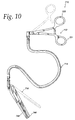
- FIG. 10 is a perspective view of a disposable embodiment made in accordance with the principles of the present invention.
- FIGS. 11 and 12 are cross-sectional views of the coupling arrangement between the jaw actuating means and the tissue engaging means of the embodiment of FIG. 10.
- FIGS. 13 and 14 are cross-sectional views of the coupling arrangement between the jaw actuating means and the handle assembly of the embodiment of FIG. 10.
- FIG. 15 a is a cross-sectional view of the coupling arrangement of FIGS. 11 and 12, in the locked position.
- FIG. 15 b is a cross-sectional view taken along the plane of line 15 a-15 a of FIG. 15a.
- FIG. 16 a is a cross-sectional view of the coupling arrangement of FIGS. 11 and 12, in the unlocked position.
- FIG. 16 b is a cross-sectional view taken along the plane of
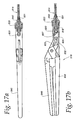
line 16 a-16 a of FIG. 16a. - FIG. 17 is a cross-sectional view of an alternate embodiment of the jaw actuating mechanism made in accordance with the principles of the present invention.
- FIG. 17 a is a top view of the jaw actuating mechanism shown in FIG. 17.
- FIG. 17 b is a cross-sectional view of the jaw actuating mechanism shown in FIG. 17, in the closed position.
- FIGS. 18 and 19 are cross-sectional views of an alternate embodiment of the coupling arrangement between the jaw actuating means and the handle assembly made in accordance with the principles of the present invention.
- FIG. 18 a is an enlarged view of the coupling arrangement of FIG. 18.
- FIG. 19 a is an enlarged view of the coupling arrangement of FIG. 19.
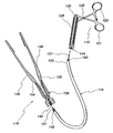
- Referring first to FIG. 1, a
surgical device 10 made in accordance with the principles of the present invention is shown. Thesurgical device 10 generally includes ahandle portion 12, ashaft member 14, andtissue engaging means 16. Although the figures depict a clamping device, it should be understood that the principles of the present invention are not limited to clamping devices and can be applied to other surgical devices such as, for example, scissors, forceps, dissectors, and retractors. - The
handle portion 12 functions to move the tissue engaging means 16 between open and closed positions. Thehandle portion 12 comprises aratchet handle assembly 19 having an angled handle. It should be understood that alternate handle assemblies having different orientations or ratchet designs could also be employed. Thehandle assembly 19 of the present invention includes a pair ofelongate legs pivot element 26. Ashaft support element 28 for theshaft member 14 is mounted to the proximal end ofleg 21. Whileleg 21 remains stationary with respect to theshaft support element 28,leg 23 moves with respect toleg 21 about thepivot element 26. Additionally, the proximal end ofleg 23 is operatively connected to an actuating means 31 which extends axially through theshaft member 14 and is operatively coupled to thetissue engaging means 16. In the preferred embodiment, the actuating means 31 comprises a cable. However, other alternate equivalent actuating means could also be employed. - The
handle assembly 19 is further provided with aratcheting mechanism 35 which is mounted on one of the legs and which interacts with the other leg to hold the tissue engaging means in the closed position. To move the tissue engaging means to the open position,lever 36 is depressed to releaseleg 23 and the tissue engaging means from the closed position. To move the tissue engaging means from the open position to the closed position,leg 23 is pushed towardleg 21, the proximal end ofleg 23 pulling back on the actuating means 31 and thereby actuating the tissue engaging means. Actuation of the tissue engaging means will be discussed in more detail below. - An alternate handle assembly and ratcheting mechanism that could be used with the present invention is shown in FIG. 2. The
handle assembly 19 includes twoelongate legs lateral extension - In an alternate embodiment of the handle assembly, shown in FIG. 3,
leg 123 can be mounted on ashaft support element 128 forshaft member 114 whileleg 121 moves about thepivot element 126. The proximal end ofleg 121 is operatively connected topiston 130 which reciprocates axially withinshaft support element 128. Whenleg 121 is moved towardleg 123,leg 121 acts uponpiston 130 which in turn pushes on the actuating means 131. The actuating means 131 in turn acts on thetissue engaging means 116. - The present invention can also be provided with a mechanism that enables the
handle assembly 19 to rotate freely relative to theshaft member 14 to allow the handle to lie flat on the operating table and out of the surgeon's way. FIG. 4 shows the detailed view of this mechanism. Asknob 39 is loosened from its attachment with thesupport element 28 of the handle assembly, the force applied by theknob 39 against bearing 40 andgasket 41 is removed. Consequently, theshaft member 14 can then rotate freely with respect to thesupport element 28. To set the handle assembly in the desired position with respect to the shaft member, theknob 39 is tightened against thesupport element 28, thereby acting against the gasket. Thegasket 41 thereby functions as a brake, preventing the shaft member to be rotated with respect to the handle assembly after tightening. - The surgical device is further provided with a
shaft member 14 which connects thehandle assembly 12 to thetissue engaging means 16. As seen in FIG. 1, one end of theshaft member 14 is operatively coupled to theshaft support element 28 of thehandle assembly 19 while the opposite end of theshaft member 14 is operatively coupled to thetissue engaging means 16. In the present invention, the shape of theshaft member 14 can be reconfigured in order to enable proper positioning of the tissue engaging means to predetermined body locations. Theshaft member 14 can be manipulated to the desired shape to avoid obstructions in an area of work or placed out of the way of the surgeon. It can take a number of forms to accomplish its function. - The shaft member can take a malleable form. Due to its malleable nature, the shaft can be placed in various arrangements to reach desired body locations. In such an embodiment of the present invention, the shaft member comprises a malleable tube with the actuating means extending axially there through. One end of the actuating means is operatively connected to the tissue engaging means while the other end is operatively coupled to the handle assembly. In one embodiment of the present invention, the ends of the actuating means can be coupled to the tissue engaging means and to the handle assembly via a ball and socket coupling. Each end of the actuating means is provided with a member in the shape of a ball which mates with a socket carried by the tissue engaging means and the handle assembly. FIG. 9 a is a detailed view of the ball and socket coupling arrangement between the actuating means and the tissue engaging means. However, alternate equivalent coupling means could also be utilized.
- The malleable tube of the shaft member could comprise tubing made of soft metal such as, for example, annealed stainless steel, brass, or aluminum, or wound tubing made of steel that is bendable and that can be placed in different shapes. Such a wound tubing embodiment of the
shaft member 14 is depicted in FIGS. 7-7 b. For a soft metal tube, the bending moment required to create a permanent set in the shaft in the range of approximately 0.5 in-lbs to 8 in-lbs, and preferably approximately 2 in-lbs. Alternately, theshaft member 414 could comprise a dual-channeledtube 416 having the actuating means extending through onechannel 419 and amalleable rod 422 extending through theother channel 425 along the length of the tube. Thechannel 419 housing the jaw actuating means (not shown) preferably extends through the center of thetube 416, with thechannel 425 housing themalleable rod 422 extending off-center, as shown in FIG. 5. Alternately, themalleable rod 422 can be positioned in other locations in thetube 416 with respect to its center. Due to the presence of themalleable rod 422, thetube 416 can be placed in various shapes. In a further alternate embodiment, a plurality of malleable rods, rather than a single malleable rod, can be employed to keep the tube in the desired shape. - The shaft member can also take a form that is both flexible and rigid. This form has the ability to be flexible so that the surgeon can form a predetermined shape to fit into a particular body opening and pathway. The state of the shaft can be changed from rigid to flexible and vice versa. Such an embodiment of the present invention is shown in FIG. 1 and in detail in FIGS. 7 c-7 e. The
shaft member 14 comprises a series of interconnected ball andsocket segments 38 through which theactuating cable 31 passes. FIGS. 7d-7 e show the cross-section of a typical ball and socket segment, while FIG. 7e shows the interaction between adjacent segments when the shaft member is placed in a desired shape. Referring back to FIG. 1, a tighteningknob 42 is also provided adjacent theshaft support element 28 which can be actuated in order to exert axial compression on thesegments 38. This compression allows the ball andsocket segments 38 of theshaft member 14 to be locked in any shape selected by the surgeon or other user of the surgical device. - Alternately, the shaft member comprises a flexible tube with the actuating cable extending axially there through. A second applier instrument that is malleable grasps the shaft member and together the two are inserted into the incision. Once the tissue engaging means are in the closed position, the applier instrument is released and removed.
- The surgical device is further provided with a tissue engaging means 16 which functions to grasp, secure, and occlude body tissue and conduits. The tissue engaging means 16 includes a pair of
jaws hinge 50. The jaws are moveable by various mechanisms between an open position and a closed position. The tissue engaging means can also be provided with acompression return spring 53 to assist the jaws in returning to the open position. - Since it is important to surgeons to reduce the size and bulk of the hinge of the jaws in order to increase visualization and to minimize the space the tissue engaging means occupies, in one embodiment of the present invention, the jaws are coaxial with the longitudinal axis of the shaft member. This orientation, which is shown in FIGS. 3, 6, 8 and 9, reduces the size and bulk of the hinge while still maintaining the strength required by the jaws. However, the tissue engaging means can be placed in alternate arrangements with respect to the shaft member. For example, in FIG. 1, the tissue engaging means is arranged at approximately a 90° angle with respect to the shaft member.
- In one embodiment of the invention, the shaft member is separable from the tissue engaging means. In use, the shaft member is utilized to place the tissue engaging means in the location desired. The shaft member is then released from the tissue engaging means and removed from the patient's body, leaving the tissue engaging means within the body. The tissue engaging means has a suture or tether attached to it, which extends out of the incision. When the tissue engaging means is to be removed, the shaft member is inserted back into the incision and is guided to the tissue engaging means by the suture or tether. The shaft member then is coupled to the tissue engaging means and the entire device is removed.
- The jaws can be actuated by a number of different mechanisms, as shown in FIGS. 3, 6, 8, 9, and 10. Despite the use of a non-rigid shaft member, the present invention is capable of exerting a force on the tissue engaging means in the range of approximately 10-20 lbs. In the embodiment of FIG. 3, the hinged end of each jaw is provided with a reduced
thickness portion jaw actuating member 156 mates with the reduced thickness portions of the jaws. In use, thehandle assembly 112 is actuated, thereby pushing the actuating means 131 forward. The actuating means 131 in turn pushes the actuatingmember 156, thereby causing it to slide forward and out of the reduced thickness portions, as shown in FIG. 3a. This motion squeezes thejaws jaws - In the alternate embodiment of FIGS. 6 a to 6 c, the hinged end of each jaw is provided with a
hole 259 which interacts with ahook 261 provided at the end of theactuating cable 231.Spring 253 is provided to maintain thejaws jaws cable 231 and hook 261 back through theshaft member 214. As thecable 231 is pulled back, thejaws conical end member 264 provided on theshaft member 214. - FIG. 8 depicts a further alternate embodiment of the jaw actuating mechanism. The mechanism includes a
cylindrical clevis 520 having twolongitudinal slots clevis 520 further includes a longitudinal cut-out 527 along its length. Thejaws clevis 520. The opposite end of theclevis 520 is provided with acylindrical extension 529 through which the jaw actuating mechanism extends. In this embodiment, the jaw actuating mechanism comprises awire driver 531 which extends through thecylindrical extension 529 and is operatively connected to one end of the jaws. - The
jaws diagonal slot screw 572 extending transversely across the longitudinal cut-out 527. The remainder of the jaws, the tissue engaging ends, extend from theclevis 520. - The end of the
wire driver 531 which is coupled to thejaws hook 561. As seen in FIG. 8a, a portion of thehook 561 is accommodated within each of the longitudinal slots. The remaining portion of the hook is coupled to theslots driver 531 is pushed toward the jaws. This motion causes thehook 561 to travel to one end of each of theslots jaws driver 531 is moved in the direction away from the jaws, thereby causing the driver to move to the opposite end of theslots - A further preferred alternate embodiment of the present invention is depicted in FIG. 9. The
surgical device 510 generally includes ahandle assembly 512 comprisingshaft support 528 andlegs shaft member 514 with anactuating cable 531 extending therethrough, and tissue engaging means 516 includingjaws actuating cable 531 is coupled to theleg 523 and tojaw 646 by a ball and socket arrangement, as mentioned above and as shown in detail in FIG. 9a. Whenleg 523 of the handle assembly is moved towardleg 521, this movement pulls on theactuating cable 531. Theactuating cable 531 in turn pullsjaw 646, causing it to move towardjaw 648 and to the closed position. When it is desired to return the jaws to the opened position,leg 523 is released, thereby releasing the force on the cable and returning the jaws to the open position. - In the embodiment of FIG. 9, the
shaft member 514 can take one of two forms. Theshaft member 514 can comprise the dual-channeled tube, as discussed above and shown in FIG. 5. Alternately, the shaft member can be comprised of tubing made of soft metal such as, for example, annealed stainless steel, brass or aluminum that is bendable and that can be placed in different shapes. In either instance, the shaft member is of a malleable type so that it can be placed in various arrangements to reach desired body locations. - In order to save the time and costs involved in sterilizing the surgical device and to reduce the cost and waste involved with fully disposable devices, the surgical device of the present invention can be made in part of disposable material so that the remainder of the surgical device is reusable. In one embodiment of the present invention, the tissue engaging means and the shaft member are made of disposable material, and a handle portion is made of re-useable material such as stainless steel. Alternately, only the tissue engaging means is made of disposable material, and the shaft member and the handle portion of re-useable material.
- One such disposable device is shown in FIG. 10. The
device 710 includes adisposable shaft member 714 operatively coupled to the tissue engaging means 716 and to thehandle assembly 712, both made of re-useable material. Theshaft member 714 is comprised of a malleable tube, preferably of a soft metal such as, for example, annealed stainless steel, brass or aluminum, having a plastic covering for cosmetic purposes. Alternately, theshaft member 714 is comprised of a malleable plastic tube, preferably of polyethylene or some other suitable plastic extrusion. - A jaw actuating means 731, comprising either a flexible cable or rod, extends through the
tube 715, the actuating means 731 being capable of sliding freely within the tube. Each end of the actuating means 731 extends from a respective end of themalleable tube 715 and is provided with aspherical ball handle assembly 712 are provided with amating socket spherical ball malleable tube 715 is coupled to the tissue engaging means 716 and to thehandle assembly 712 by the mating of thespherical balls sockets - Referring to FIGS. 11 and 12, one of the
jaws 748 of the tissue engaging means 716 is provided at one end with acylinder 733. Theother jaw 746 of the tissue engaging means 716 is provided with abolt 737. Thebolt 737 includes a cut-outportion 739 in which one end ofjaw 746 pivots. Thebolt 737 then extends away fromjaw 746 through thecylinder 733 to mate with the jaw actuating means 731. As mentioned above, thebolt 737 is provided with thesocket 724 which mates with thespherical ball 720 of the jaw actuating means 731. Thecylinder 733 is also provided with aspring 741 which biases thebolt 737 and in turn thejaw 746 to the open position. To actuate the jaws of the tissue engaging means from the open position shown in FIG. 11 to a closed position, thehandle assembly 712 is actuated to pull one end of the jaw actuating means 731 in the direction away from thetissue engaging means 716. Due to the ball and socket coupling, thebolt 737 is also pulled away from thetissue engaging means 716. This action causes thebolt 737 to act onjaw 746 via the cut-outportion 739, thejaw 746 pivoting to the closed position shown in FIG. 12. Since the jaws are spring biased to the open position, upon release of the pressure on the legs of the handle assembly, the jaws are returned to the open position. - As shown in FIGS. 13 and 14, a similar ball and socket coupling is employed to couple the jaw actuating means 731 to the
handle assembly 712. One of the legs of thehandle assembly 712 is provided at one end with acylinder 735 while theother leg 723 is provided with abolt 739. Thebolt 739 includes a cut-outportion 743 in which the end ofleg 723 pivots. Thebolt 739 then extends away from theleg 723 through thecylinder 735 to mate with the jaw actuating means 731. To mate with thespherical ball 722 of the jaw actuating means 731, thebolt 739 is provided with asocket 726. In order to actuate the tissue engaging means 716 to the closed position, thelegs handle assembly 712 are moved from the position shown in FIG. 13, in which the legs are apart from one another, to the position shown in FIG. 14, in which the legs are brought together. With this action,leg 723 acts on thebolt 739 pulling it in a direction away from thetissue engaging means 716. Thebolt 739 in turn acts on the jaw actuating means 731, pulling it in a direction away from thetissue engaging means 716. As discussed above, this action causes the opposite end of the jaw actuating means 731 to act onjaw 746 of the tissue engaging means 716, thereby bringing the jaws together to the closed position, as shown in FIG. 12. - To enable the
shaft member 714 to be separated from thehandle assembly 712 and the tissue engaging means 716 and thus disposable, lockingclips opening 755 generally in the shape of the numeral “8.” To lock theball 720 of the jaw actuating means 731 to thesocket 724 of thebolt 737, thelocking clip 751 is placed in the position shown in FIG. 15b. To unlock theball 720 of the jaw actuating means 731 from thesocket 724 of thebolt 737 and thus allow theshaft member 714 to be separated and disposed, thelocking clip 751 is placed in the position shown in FIG. 16b. - Another preferred alternate embodiment of the present invention is depicted in FIGS. 17-19. The
device 810 includes a tissue engaging means 816 withjaws shaft member 814, and ahandle assembly 812 withhandles shaft member 814 is comprised of a malleable tube, preferably of a soft metal such as, for example, annealed stainless steel, brass or aluminum. Each end of the shaft member is provided with aterminal member shaft member 814. The jaw actuating means is provided at each end with aterminal member spherical ball - Referring to FIGS. 17-17 b, the tissue engaging means 816 is carried by a
housing 824. Within thehousing 824, abolt member 837 moves, the bolt member being provided with apin 832 and asocket 838 which cooperates with thespherical ball 820 of the jaw actuating means 831.Jaw 846 of the tissue engaging means is provided with aslot 825 which is operatively coupled to abolt member 837 viapin 832. Theshaft member 814 is coupled to thehousing 824 by the cooperation betweenterminal member 840 andcap 833. To couple the shaft member with the housing,terminal member 840 is abutted against thehousing 840 and thecap 833 is then attached tohousing 824 via a suitable means such as screw threads. - To actuate the tissue engaging means from its open position, shown in FIG. 17, to its closed position, shown in FIG. 17 b, the jaw actuating means is pulled in a direction away from the tissue engaging means. This movement in turn causes the
bolt member 837 to move away from the tissue engaging means. As the bolt member moves away, thepin 832 travels from one end of the slot to the other, thereby causing the jaw to pivot about thefulcrum 850 to its closed position. The coupling arrangement between the jaw actuating means and the tissue engaging means allows the force required to remain relatively low, particularly when taking into consideration the long, thin configuration of the shaft member. Once the jaw actuating means is released, it moves back towards the jaw actuating means and thejaw 846 returns to its open position. - Referring to FIGS. 18-19, handle 821 of the handle assembly is provided at one end with a
housing 852. Within thehousing 852, abolt member 839 moves, thebolt member 839 being provided with asocket 855 for coupling with the jaw actuating means and a cut-outportion 843 in which the end ofleg 823 pivots. Theshaft member 814 is coupled to thehousing 852 by the cooperation betweenterminal member 841 andcap 834. To couple theshaft member 814 with thehousing 852,terminal member 841 is abutted against thehousing 852 and thecap 834 is then attached tohousing 852 via a suitable means such as screw threads. - In order to actuate the tissue engaging means 816 to the closed position, the
legs handle assembly 812 are moved from the position shown in FIG. 18, in which the legs are apart from one another, to the position shown in FIG. 19, in which the legs are brought together. With this action,leg 823 acts on thebolt member 839 pulling it in a direction away from thetissue engaging means 816. Thebolt member 839 in turn acts on the jaw actuating means 831, pulling it in a direction away from thetissue engaging means 816. As discussed above, this action causes the opposite end of the jaw actuating means 831 to act onjaw 846 of the tissue engaging means 816, thereby bringing the jaws together to the closed position, as shown in FIG. 17b. - It should be understood that various changes in modifications to the preferred embodiment described herein will be apparent to those skilled in the art. Such changes and modifications can be made without departing from the spirit and scope of the present invention and without diminishing its attendant advantages. It is therefore intended that such changes and modifications be within the scope of the claims.
Claims (36)
1. A surgical device having a longitudinal axis extending between a proximal end and a distal end, comprising:
tissue engaging means including first and second opposed jaws for grasping, securing, and occluding body tissue and conduits;
a shaft member operatively coupled to the tissue engaging means, the shaft member capable of being placed in different curvatures; and
a handle assembly operatively coupled to the shaft member and to the tissue engaging means.
2. The surgical device of claim 1 further comprising a jaw actuating means for actuating the jaws of the tissue engaging means between an open position and a closed position, the actuating means being operatively connected to the tissue engaging means and to the handle assembly.
3. The surgical device of claim 2 wherein the shaft member comprises a malleable tube with the jaw actuating means extending axially there through.
4. The surgical device of claim 2 wherein the shaft member comprises a series of interconnected ball and socket segments with the jaw actuating means extending axially there through.
5. The surgical device of claim 2 wherein the shaft member comprises soft metal tubing with the jaw actuating means extending axially there through.
6. The surgical device of claim 2 wherein the shaft member comprises wound metal tubing with the jaw actuating means extending axially there through.
7. The surgical device of claim 2 wherein the shaft member comprises a dual-channeled plastic tube having a first and a second channel, the jaw actuating means extending axially through the first channel and a malleable rod extending axially through the second channel.
8. The surgical device of claim 1 further comprising a compression return spring for biasing the tissue engaging means to an open position.
9. The surgical device of claim 1 wherein the tissue engaging means further includes a hinged end at which the jaws are hinged together.
10. The surgical device of claim 9 further comprising a jaw actuating means for actuating the jaws of the tissue engaging means between an open position and a closed position, the actuating means operatively connected to the tissue engaging means and to the handle assembly.
11. The surgical device of claim 10 wherein the jaw actuating means comprises a drive rod.
12. The surgical device of claim 11 wherein a jaw actuating member is provided at the hinged end of the tissue engaging means for squeezing together the jaws of the tissue engaging means in response to actuation of the drive rod by the handle assembly.
13. The surgical device of claim 10 wherein the jaw actuating means comprises a cable.
14. The surgical device of claim 13 wherein the hinged end of the tissue engaging means includes a hole there through, the hole interacting with a hook provided at one end of the cable.
15. The surgical device of claim 14 wherein the shaft member is provided with a end member which, upon actuation of the cable by the handle assembly, interacts with the jaws of the tissue engaging means to bring the jaws to the closed position.
16. The surgical device of claim 10 wherein the jaw actuating means comprises a wire member having a hook at one end operatively coupled to the jaws of the tissue engaging means.
17. The surgical device of claim 18 wherein each jaw is provided with a diagonal slot at one end, the hook of the wire member interacting with the diagonal slots of the jaws to move the jaws between the open and closed positions.
18. The surgical device of claim 17 further provided with a clevis which houses a portion of the wire member and the slotted ends of the jaws.
19. The surgical device of claim 10 wherein one jaw of the tissue engaging means is provided with a slot at one end, the jaw actuating means being operatively coupled with the slot via a pin.
20. The surgical device of claim 11 wherein the tissue engaging means is further provided with a socket for coupling to the jaw actuating means.
21. The surgical device of claim 20 wherein one end of the jaw actuating means is provided with a ball for coupling to the socket of the tissue engaging means.
22. The surgical device of claim 21 wherein another end of the jaw actuating means is provided with a ball for coupling to the handle assembly.
23. The surgical device of claim 1 wherein the tissue engaging means and the shaft member are disposable.
24. The surgical device of claim 1 wherein the tissue engaging means is disposable
25. The surgical device of claim 1 wherein the shaft member is disposable.
26. A surgical device having a longitudinal axis extending between a proximal end and a distal end, comprising:
tissue engaging means including first and second opposed jaws for grasping, securing, and occluding body tissue and conduits;
a shaft member operatively coupled to the tissue engaging means, the shaft member capable of being placed and locked in different curvatures;
a handle assembly operatively coupled to the shaft member and to the tissue engaging means; and
a jaw actuating means for actuating the jaws of the tissue engaging means between an open and a closed position.
27. The surgical device of claim 26 wherein the jaw actuating means comprises a cable operatively connected to the tissue engaging means, extending through the shaft member, and operatively connected to the handle assembly.
28. The surgical device of claim 27 wherein the shaft member comprises a series of interconnected ball and socket segments with the jaw actuating cable extending axially there through.
29. The surgical device of claim 28 further comprising a tightening knob for exerting axial compression on the segments, thereby allowing the shaft member to be locked in any shape.
30. The surgical device of claim 27 wherein the shaft member comprises a flexible tube with the jaw actuating cable extending axially there through.
31. The surgical device of claim 30 further comprising a malleable applier instrument for grasping the jaws of the tissue engaging means for insertion together into an incision.
32. The surgical device of claim 31 wherein the malleable applier instrument is capable of being released and removed from the incision once the jaws of the tissue engaging means have been actuated to the closed position.
33. A surgical device having a longitudinal axis extending between a proximal end and a distal end, comprising:
tissue engaging means including first and second opposed jaws for grasping, securing, and occluding body tissue and conduits;
a shaft member operatively coupled to the tissue engaging means, the shaft member being constructed of malleable material and thus capable of being placed in different curvatures;
a handle assembly operatively coupled to the shaft member and to the tissue engaging means; and
a jaw actuating means for actuating the jaws of the tissue engaging means between an open and a closed position, the jaw actuating means extending axially through the shaft member and being provided with coupling means at each end which enable the jaw actuating means and the shaft member to be separated from the remainder of the device to be disposed.
34. The surgical device of claim 33 wherein the tissue engaging means is provided with a socket for coupling to the jaw actuating means.
35. The surgical device of claim 34 wherein the coupling means of the jaw actuating means comprises a first ball provided at one end of the actuating means for coupling with the socket of the tissue engaging means.
36. The surgical device of claim 35 wherein the coupling means of the jaw actuating means further comprises a second ball provided at another end of the jaw actuating means for coupling with the handle assembly.
Priority Applications (1)
| Application Number | Priority Date | Filing Date | Title |
|---|---|---|---|
| US10/412,044 US20030191494A1 (en) | 1997-09-25 | 2003-04-11 | Surgical device with malleable shaft |
Applications Claiming Priority (3)
| Application Number | Priority Date | Filing Date | Title |
|---|---|---|---|
| US08/936,394 US6139563A (en) | 1997-09-25 | 1997-09-25 | Surgical device with malleable shaft |
| US43252399A | 1999-11-03 | 1999-11-03 | |
| US10/412,044 US20030191494A1 (en) | 1997-09-25 | 2003-04-11 | Surgical device with malleable shaft |
Related Parent Applications (1)
| Application Number | Title | Priority Date | Filing Date |
|---|---|---|---|
| US43252399A Division | 1997-09-25 | 1999-11-03 |
Publications (1)
| Publication Number | Publication Date |
|---|---|
| US20030191494A1 true US20030191494A1 (en) | 2003-10-09 |
Family
ID=25468567
Family Applications (2)
| Application Number | Title | Priority Date | Filing Date |
|---|---|---|---|
| US08/936,394 Expired - Lifetime US6139563A (en) | 1997-09-25 | 1997-09-25 | Surgical device with malleable shaft |
| US10/412,044 Abandoned US20030191494A1 (en) | 1997-09-25 | 2003-04-11 | Surgical device with malleable shaft |
Family Applications Before (1)
| Application Number | Title | Priority Date | Filing Date |
|---|---|---|---|
| US08/936,394 Expired - Lifetime US6139563A (en) | 1997-09-25 | 1997-09-25 | Surgical device with malleable shaft |
Country Status (12)
| Country | Link |
|---|---|
| US (2) | US6139563A (en) |
| EP (6) | EP1340466A1 (en) |
| JP (2) | JP4488257B2 (en) |
| AT (1) | ATE322218T1 (en) |
| AU (1) | AU756859B2 (en) |
| CA (5) | CA2517468C (en) |
| CY (1) | CY1105218T1 (en) |
| DE (1) | DE69834144T2 (en) |
| DK (1) | DK1342451T3 (en) |
| ES (1) | ES2261868T3 (en) |
| PT (1) | PT1342451E (en) |
| WO (1) | WO1999015089A1 (en) |
Cited By (19)
| Publication number | Priority date | Publication date | Assignee | Title |
|---|---|---|---|---|
| US20030181945A1 (en) * | 2002-03-15 | 2003-09-25 | Nmt Medical, Inc. | Coupling system useful in placement of implants |
| US20080021278A1 (en) * | 2006-07-24 | 2008-01-24 | Leonard Robert F | Surgical device with removable end effector |
| US20090069842A1 (en) * | 2007-09-11 | 2009-03-12 | Woojin Lee | Surgical instrument |
| US7666203B2 (en) | 2003-11-06 | 2010-02-23 | Nmt Medical, Inc. | Transseptal puncture apparatus |
| US7691112B2 (en) | 2003-09-11 | 2010-04-06 | Nmt Medical, Inc. | Devices, systems, and methods for suturing tissue |
| US20100094287A1 (en) * | 2008-10-09 | 2010-04-15 | Tyco Heathcare Group Lp | Apparatus, System, and Method for Performing an Endoscopic Electrosurgical Procedure |
| US8292910B2 (en) | 2003-11-06 | 2012-10-23 | Pressure Products Medical Supplies, Inc. | Transseptal puncture apparatus |
| US20150320438A1 (en) * | 2014-04-22 | 2015-11-12 | Ethicon Endo-Surgery, Inc. | Ultrasonic surgical instrument with end effector having restricted articulation |
| KR20150127284A (en) * | 2013-03-18 | 2015-11-16 | 인튜어티브 서지컬 오퍼레이션즈 인코포레이티드 | Surgical instrument drive element, and related devices, systems, and methods |
| US9375218B2 (en) | 2006-05-03 | 2016-06-28 | Datascope Corp. | Systems and methods of tissue closure |
| EP3437571A3 (en) * | 2009-12-22 | 2019-04-03 | Cook Medical Technologies LLC | Medical devices with detachable pivotable jaws |
| US10258363B2 (en) | 2014-04-22 | 2019-04-16 | Ethicon Llc | Method of operating an articulating ultrasonic surgical instrument |
| US10420573B2 (en) | 2015-02-02 | 2019-09-24 | Olympus Corporation | Surgical tool |
| US10485545B2 (en) | 2013-11-19 | 2019-11-26 | Datascope Corp. | Fastener applicator with interlock |
| US20220031324A1 (en) * | 2020-07-28 | 2022-02-03 | Cilag Gmbh International | Surgical instruments with dual spherical articulation joint arrangements |
| EP3903709A4 (en) * | 2018-12-27 | 2022-03-16 | Beijing Surgerii Technology Co., Ltd. | Surgical tool |
| US11446046B2 (en) * | 2017-08-26 | 2022-09-20 | Nutech Ventures | Tool exchange system for a surgical robot |
| US11653928B2 (en) | 2018-03-28 | 2023-05-23 | Datascope Corp. | Device for atrial appendage exclusion |
| US11844913B2 (en) | 2012-03-23 | 2023-12-19 | Boston Scientific Medical Device Limited | Transseptal puncture apparatus and method for using the same |
Families Citing this family (237)
| Publication number | Priority date | Publication date | Assignee | Title |
|---|---|---|---|---|
| US6161543A (en) * | 1993-02-22 | 2000-12-19 | Epicor, Inc. | Methods of epicardial ablation for creating a lesion around the pulmonary veins |
| US6719755B2 (en) | 1996-10-22 | 2004-04-13 | Epicor Medical, Inc. | Methods and devices for ablation |
| US6311692B1 (en) | 1996-10-22 | 2001-11-06 | Epicor, Inc. | Apparatus and method for diagnosis and therapy of electrophysiological disease |
| US7052493B2 (en) | 1996-10-22 | 2006-05-30 | Epicor Medical, Inc. | Methods and devices for ablation |
| US6139563A (en) * | 1997-09-25 | 2000-10-31 | Allegiance Corporation | Surgical device with malleable shaft |
| US8709007B2 (en) * | 1997-10-15 | 2014-04-29 | St. Jude Medical, Atrial Fibrillation Division, Inc. | Devices and methods for ablating cardiac tissue |
| WO2002080786A1 (en) | 2001-04-06 | 2002-10-17 | Sherwood Services Ag | Electrosurgical instrument which reduces collateral damage to adjacent tissue |
| US6726686B2 (en) | 1997-11-12 | 2004-04-27 | Sherwood Services Ag | Bipolar electrosurgical instrument for sealing vessels |
| US7435249B2 (en) | 1997-11-12 | 2008-10-14 | Covidien Ag | Electrosurgical instruments which reduces collateral damage to adjacent tissue |
| US6228083B1 (en) | 1997-11-14 | 2001-05-08 | Sherwood Services Ag | Laparoscopic bipolar electrosurgical instrument |
| US8308719B2 (en) | 1998-09-21 | 2012-11-13 | St. Jude Medical, Atrial Fibrillation Division, Inc. | Apparatus and method for ablating tissue |
| US7364577B2 (en) | 2002-02-11 | 2008-04-29 | Sherwood Services Ag | Vessel sealing system |
| US7582087B2 (en) | 1998-10-23 | 2009-09-01 | Covidien Ag | Vessel sealing instrument |
| US7118570B2 (en) | 2001-04-06 | 2006-10-10 | Sherwood Services Ag | Vessel sealing forceps with disposable electrodes |
| US7267677B2 (en) | 1998-10-23 | 2007-09-11 | Sherwood Services Ag | Vessel sealing instrument |
| US6626929B1 (en) * | 1999-04-15 | 2003-09-30 | Classic Wire Cut | Surgical instrument with locking ratchet apparatus and method |
| EP1207788A4 (en) * | 1999-07-19 | 2009-12-09 | St Jude Medical Atrial Fibrill | Apparatus and method for ablating tissue |
| US20030109875A1 (en) | 1999-10-22 | 2003-06-12 | Tetzlaff Philip M. | Open vessel sealing forceps with disposable electrodes |
| US6692491B1 (en) | 2000-03-24 | 2004-02-17 | Scimed Life Systems, Inc. | Surgical methods and apparatus for positioning a diagnostic or therapeutic element around one or more pulmonary veins or other body structures |
| US6926712B2 (en) * | 2000-03-24 | 2005-08-09 | Boston Scientific Scimed, Inc. | Clamp having at least one malleable clamp member and surgical method employing the same |
| US6743239B1 (en) * | 2000-05-25 | 2004-06-01 | St. Jude Medical, Inc. | Devices with a bendable tip for medical procedures |
| AU2002224520A1 (en) * | 2000-07-21 | 2002-02-05 | Atropos Limited | A cannula |
| AU2002224519A1 (en) * | 2000-07-21 | 2002-02-05 | Atropos Limited | A surgical instrument |
| AU2001288462A1 (en) | 2000-08-30 | 2002-03-13 | Cerebral Vascular Applications Inc. | Medical instrument |
| US6986772B2 (en) | 2001-03-01 | 2006-01-17 | Michelson Gary K | Dynamic lordotic guard with movable extensions for creating an implantation space posteriorly in the lumbar spine |
| WO2002069891A2 (en) | 2001-03-01 | 2002-09-12 | Michelson Gary K | Dynamic lordotic guard with movable extensions for creating an implantation space posteriorly in the lumbar spine and method for use thereof |
| US6896680B2 (en) * | 2001-03-01 | 2005-05-24 | Gary K. Michelson | Arcuate dynamic lordotic guard with movable extensions for creating an implantation space posteriorly in the lumbar spine |
| US7473253B2 (en) | 2001-04-06 | 2009-01-06 | Covidien Ag | Vessel sealer and divider with non-conductive stop members |
| US6676676B2 (en) | 2001-05-02 | 2004-01-13 | Novare Surgical Systems | Clamp having bendable shaft |
| US6544274B2 (en) | 2001-05-02 | 2003-04-08 | Novare Surgical Systems, Inc. | Clamp having bendable shaft |
| US6685715B2 (en) | 2001-05-02 | 2004-02-03 | Novare Surgical Systems | Clamp having bendable shaft |
| US6916332B2 (en) * | 2001-05-23 | 2005-07-12 | Scimed Life Systems, Inc. | Endoluminal fundoplication device and related method for installing tissue fastener |
| US7041084B2 (en) | 2001-05-24 | 2006-05-09 | Fojtik Shawn P | Hand-held, hand operated power syringe and methods |
| US6755338B2 (en) * | 2001-08-29 | 2004-06-29 | Cerebral Vascular Applications, Inc. | Medical instrument |
| US7867243B2 (en) * | 2001-09-06 | 2011-01-11 | Design Standards Corporation | Tissue grasping and clipping/stapling device |
| US7094245B2 (en) | 2001-10-05 | 2006-08-22 | Scimed Life Systems, Inc. | Device and method for through the scope endoscopic hemostatic clipping |
| FR2831417B1 (en) * | 2001-10-30 | 2004-08-06 | Eurosurgical | SURGICAL INSTRUMENT |
| US7753908B2 (en) | 2002-02-19 | 2010-07-13 | Endoscopic Technologies, Inc. (Estech) | Apparatus for securing an electrophysiology probe to a clamp |
| US7785324B2 (en) | 2005-02-25 | 2010-08-31 | Endoscopic Technologies, Inc. (Estech) | Clamp based lesion formation apparatus and methods configured to protect non-target tissue |
| US6932816B2 (en) | 2002-02-19 | 2005-08-23 | Boston Scientific Scimed, Inc. | Apparatus for converting a clamp into an electrophysiology device |
| US8454628B2 (en) * | 2002-09-20 | 2013-06-04 | Syntheon, Llc | Surgical fastener aligning instrument particularly for transoral treatment of gastroesophageal reflux disease |
| US6966919B2 (en) * | 2002-09-20 | 2005-11-22 | Id, Llc | Instrument for applying a surgical fastener particularly for the transoral treatment of gastroesophageal reflux disease (GERD) |
| US7033378B2 (en) * | 2002-09-20 | 2006-04-25 | Id, Llc | Surgical fastener, particularly for the endoluminal treatment of gastroesophageal reflux disease (GERD) |
| US7678122B2 (en) * | 2002-09-20 | 2010-03-16 | Id, Llc | Method of performing a treatment for gastroesophagheal reflux disease (GERD) |
| US7276068B2 (en) | 2002-10-04 | 2007-10-02 | Sherwood Services Ag | Vessel sealing instrument with electrical cutting mechanism |
| US7931649B2 (en) | 2002-10-04 | 2011-04-26 | Tyco Healthcare Group Lp | Vessel sealing instrument with electrical cutting mechanism |
| US7270664B2 (en) | 2002-10-04 | 2007-09-18 | Sherwood Services Ag | Vessel sealing instrument with electrical cutting mechanism |
| US7083620B2 (en) * | 2002-10-30 | 2006-08-01 | Medtronic, Inc. | Electrosurgical hemostat |
| US7799026B2 (en) | 2002-11-14 | 2010-09-21 | Covidien Ag | Compressible jaw configuration with bipolar RF output electrodes for soft tissue fusion |
| WO2004082495A1 (en) | 2003-03-13 | 2004-09-30 | Sherwood Services Ag | Bipolar concentric electrode assembly for soft tissue fusion |
| US7160299B2 (en) | 2003-05-01 | 2007-01-09 | Sherwood Services Ag | Method of fusing biomaterials with radiofrequency energy |
| EP1617778A2 (en) | 2003-05-01 | 2006-01-25 | Sherwood Services AG | Electrosurgical instrument which reduces thermal damage to adjacent tissue |
| US7025775B2 (en) * | 2003-05-15 | 2006-04-11 | Applied Medical Resources Corporation | Surgical instrument with removable shaft apparatus and method |
| WO2004103156A2 (en) | 2003-05-15 | 2004-12-02 | Sherwood Services Ag | Tissue sealer with non-conductive variable stop members and method of sealing tissue |
| US8398632B1 (en) * | 2003-06-10 | 2013-03-19 | Medtronic Cryocath Lp | Surgical clamp having treatment elements |
| US7044946B2 (en) | 2003-06-10 | 2006-05-16 | Cryocath Technologies Inc. | Surgical clamp having treatment elements |
| US7819860B2 (en) * | 2003-06-10 | 2010-10-26 | Medtronic Cryocath Lp | Surgical clamp having trasmurality assessment capabilities |
| US7156846B2 (en) | 2003-06-13 | 2007-01-02 | Sherwood Services Ag | Vessel sealer and divider for use with small trocars and cannulas |
| US7857812B2 (en) | 2003-06-13 | 2010-12-28 | Covidien Ag | Vessel sealer and divider having elongated knife stroke and safety for cutting mechanism |
| USD956973S1 (en) | 2003-06-13 | 2022-07-05 | Covidien Ag | Movable handle for endoscopic vessel sealer and divider |
| US7150749B2 (en) | 2003-06-13 | 2006-12-19 | Sherwood Services Ag | Vessel sealer and divider having elongated knife stroke and safety cutting mechanism |
| CN1859874A (en) * | 2003-06-16 | 2006-11-08 | 伊西康内外科公司 | Surgical system with stapling instrument and retractor |
| US7960935B2 (en) | 2003-07-08 | 2011-06-14 | The Board Of Regents Of The University Of Nebraska | Robotic devices with agent delivery components and related methods |
| DE10333342B4 (en) * | 2003-07-23 | 2009-12-10 | Aesculap Ag | Surgical tubular shaft instrument |
| EP3443915B2 (en) | 2003-09-30 | 2024-01-31 | Boston Scientific Scimed, Inc. | Apparatus for deployment of a hemostatic clip |
| US20050090817A1 (en) * | 2003-10-22 | 2005-04-28 | Scimed Life Systems, Inc. | Bendable endoscopic bipolar device |
| US9848938B2 (en) | 2003-11-13 | 2017-12-26 | Covidien Ag | Compressible jaw configuration with bipolar RF output electrodes for soft tissue fusion |
| US7367976B2 (en) | 2003-11-17 | 2008-05-06 | Sherwood Services Ag | Bipolar forceps having monopolar extension |
| US7811283B2 (en) | 2003-11-19 | 2010-10-12 | Covidien Ag | Open vessel sealing instrument with hourglass cutting mechanism and over-ratchet safety |
| US7500975B2 (en) | 2003-11-19 | 2009-03-10 | Covidien Ag | Spring loaded reciprocating tissue cutting mechanism in a forceps-style electrosurgical instrument |
| US7131970B2 (en) | 2003-11-19 | 2006-11-07 | Sherwood Services Ag | Open vessel sealing instrument with cutting mechanism |
| US7442193B2 (en) | 2003-11-20 | 2008-10-28 | Covidien Ag | Electrically conductive/insulative over-shoe for tissue fusion |
| US8002770B2 (en) | 2003-12-02 | 2011-08-23 | Endoscopic Technologies, Inc. (Estech) | Clamp based methods and apparatus for forming lesions in tissue and confirming whether a therapeutic lesion has been formed |
| JP4504000B2 (en) * | 2003-12-11 | 2010-07-14 | 健純 土肥 | Bending motion member, actuator and manipulator |
| US20050131457A1 (en) * | 2003-12-15 | 2005-06-16 | Ethicon, Inc. | Variable stiffness shaft |
| US7780662B2 (en) | 2004-03-02 | 2010-08-24 | Covidien Ag | Vessel sealing system using capacitive RF dielectric heating |
| US7195631B2 (en) | 2004-09-09 | 2007-03-27 | Sherwood Services Ag | Forceps with spring loaded end effector assembly |
| US7540872B2 (en) | 2004-09-21 | 2009-06-02 | Covidien Ag | Articulating bipolar electrosurgical instrument |
| US7727256B2 (en) * | 2004-09-24 | 2010-06-01 | Arthrex, Inc. | Grasper assembly |
| US7955332B2 (en) | 2004-10-08 | 2011-06-07 | Covidien Ag | Mechanism for dividing tissue in a hemostat-style instrument |
| ATE554717T1 (en) | 2004-10-20 | 2012-05-15 | Atricure Inc | SURGICAL CLAMP |
| US8876820B2 (en) * | 2004-10-20 | 2014-11-04 | Atricure, Inc. | Surgical clamp |
| US7727231B2 (en) | 2005-01-08 | 2010-06-01 | Boston Scientific Scimed, Inc. | Apparatus and methods for forming lesions in tissue and applying stimulation energy to tissue in which lesions are formed |
| US7909823B2 (en) | 2005-01-14 | 2011-03-22 | Covidien Ag | Open vessel sealing instrument |
| US7686804B2 (en) | 2005-01-14 | 2010-03-30 | Covidien Ag | Vessel sealer and divider with rotating sealer and cutter |
| EP1838228A1 (en) * | 2005-01-19 | 2007-10-03 | Applied Medical Resources Corporation | Disposable laparoscopic instrument |
| US7491202B2 (en) | 2005-03-31 | 2009-02-17 | Covidien Ag | Electrosurgical forceps with slow closure sealing plates and method of sealing tissue |
| US20070072466A1 (en) | 2005-09-27 | 2007-03-29 | Manabu Miyamoto | Instrument for endoscope |
| CA2561034C (en) | 2005-09-30 | 2014-12-09 | Sherwood Services Ag | Flexible endoscopic catheter with an end effector for coagulating and transfecting tissue |
| EP1769765B1 (en) | 2005-09-30 | 2012-03-21 | Covidien AG | Insulating boot for electrosurgical forceps |
| US7722607B2 (en) | 2005-09-30 | 2010-05-25 | Covidien Ag | In-line vessel sealer and divider |
| US7789878B2 (en) | 2005-09-30 | 2010-09-07 | Covidien Ag | In-line vessel sealer and divider |
| US7879035B2 (en) | 2005-09-30 | 2011-02-01 | Covidien Ag | Insulating boot for electrosurgical forceps |
| US7922953B2 (en) | 2005-09-30 | 2011-04-12 | Covidien Ag | Method for manufacturing an end effector assembly |
| US8734443B2 (en) | 2006-01-24 | 2014-05-27 | Covidien Lp | Vessel sealer and divider for large tissue structures |
| US8882766B2 (en) | 2006-01-24 | 2014-11-11 | Covidien Ag | Method and system for controlling delivery of energy to divide tissue |
| US8241282B2 (en) | 2006-01-24 | 2012-08-14 | Tyco Healthcare Group Lp | Vessel sealing cutting assemblies |
| US8298232B2 (en) | 2006-01-24 | 2012-10-30 | Tyco Healthcare Group Lp | Endoscopic vessel sealer and divider for large tissue structures |
| US8679096B2 (en) | 2007-06-21 | 2014-03-25 | Board Of Regents Of The University Of Nebraska | Multifunctional operational component for robotic devices |
| US9579088B2 (en) | 2007-02-20 | 2017-02-28 | Board Of Regents Of The University Of Nebraska | Methods, systems, and devices for surgical visualization and device manipulation |
| WO2007149559A2 (en) | 2006-06-22 | 2007-12-27 | Board Of Regents Of The University Of Nebraska | Magnetically coupleable robotic devices and related methods |
| US7846177B2 (en) * | 2006-06-26 | 2010-12-07 | Carefusion 2200, Inc. | Surgical device |
| US7776037B2 (en) | 2006-07-07 | 2010-08-17 | Covidien Ag | System and method for controlling electrode gap during tissue sealing |
| US8597297B2 (en) | 2006-08-29 | 2013-12-03 | Covidien Ag | Vessel sealing instrument with multiple electrode configurations |
| US8070746B2 (en) | 2006-10-03 | 2011-12-06 | Tyco Healthcare Group Lp | Radiofrequency fusion of cardiac tissue |
| EP2081481B1 (en) | 2006-10-05 | 2015-03-11 | Covidien LP | Flexible endoscopic stitching devices |
| EP2083702B1 (en) | 2006-10-05 | 2019-02-13 | Covidien LP | Axial stitching device |
| US8795325B2 (en) * | 2006-10-05 | 2014-08-05 | Covidien Lp | Handle assembly for articulated endoscopic instruments |
| US8475453B2 (en) | 2006-10-06 | 2013-07-02 | Covidien Lp | Endoscopic vessel sealer and divider having a flexible articulating shaft |
| CN101522127B (en) | 2006-10-06 | 2011-11-16 | Tyco医疗健康集团 | Endoscopic vessel sealer and divider having a flexible articulating shaft |
| USD649249S1 (en) | 2007-02-15 | 2011-11-22 | Tyco Healthcare Group Lp | End effectors of an elongated dissecting and dividing instrument |
| US8267935B2 (en) | 2007-04-04 | 2012-09-18 | Tyco Healthcare Group Lp | Electrosurgical instrument reducing current densities at an insulator conductor junction |
| US9314298B2 (en) | 2007-04-17 | 2016-04-19 | St. Jude Medical, Atrial Fibrillation Divisions, Inc. | Vacuum-stabilized ablation system |
| WO2009014917A2 (en) * | 2007-07-12 | 2009-01-29 | Board Of Regents Of The University Of Nebraska | Methods and systems of actuation in robotic devices |
| JP2010536435A (en) | 2007-08-15 | 2010-12-02 | ボード オブ リージェンツ オブ ザ ユニバーシティ オブ ネブラスカ | Medical inflation, attachment and delivery devices and associated methods |
| US9005238B2 (en) | 2007-08-23 | 2015-04-14 | Covidien Lp | Endoscopic surgical devices |
| US8235992B2 (en) | 2007-09-28 | 2012-08-07 | Tyco Healthcare Group Lp | Insulating boot with mechanical reinforcement for electrosurgical forceps |
| US8236025B2 (en) | 2007-09-28 | 2012-08-07 | Tyco Healthcare Group Lp | Silicone insulated electrosurgical forceps |
| AU2008221509B2 (en) | 2007-09-28 | 2013-10-10 | Covidien Lp | Dual durometer insulating boot for electrosurgical forceps |
| US8221416B2 (en) | 2007-09-28 | 2012-07-17 | Tyco Healthcare Group Lp | Insulating boot for electrosurgical forceps with thermoplastic clevis |
| US8251996B2 (en) | 2007-09-28 | 2012-08-28 | Tyco Healthcare Group Lp | Insulating sheath for electrosurgical forceps |
| US8267936B2 (en) | 2007-09-28 | 2012-09-18 | Tyco Healthcare Group Lp | Insulating mechanically-interfaced adhesive for electrosurgical forceps |
| US8235993B2 (en) | 2007-09-28 | 2012-08-07 | Tyco Healthcare Group Lp | Insulating boot for electrosurgical forceps with exohinged structure |
| US9023043B2 (en) | 2007-09-28 | 2015-05-05 | Covidien Lp | Insulating mechanically-interfaced boot and jaws for electrosurgical forceps |
| US9707003B2 (en) * | 2007-10-02 | 2017-07-18 | Covidien Lp | Articulating surgical instrument |
| US8764748B2 (en) | 2008-02-06 | 2014-07-01 | Covidien Lp | End effector assembly for electrosurgical device and method for making the same |
| US8623276B2 (en) | 2008-02-15 | 2014-01-07 | Covidien Lp | Method and system for sterilizing an electrosurgical instrument |
| DE102008017298A1 (en) * | 2008-03-31 | 2009-10-01 | Karl Storz Gmbh & Co. Kg | Medical instrument with flexible use |
| US8864776B2 (en) | 2008-04-11 | 2014-10-21 | Covidien Lp | Deployment system for surgical suture |
| US8628545B2 (en) | 2008-06-13 | 2014-01-14 | Covidien Lp | Endoscopic stitching devices |
| US20110040308A1 (en) | 2008-06-13 | 2011-02-17 | Ramiro Cabrera | Endoscopic Stitching Devices |
| US8579921B2 (en) * | 2008-06-18 | 2013-11-12 | Covidien Lp | Spring-type suture securing device |
| CA2725776A1 (en) | 2008-06-19 | 2009-12-23 | Boston Scientific Scimed, Inc. | Hemostatic clipping devices and methods |
| US8469956B2 (en) | 2008-07-21 | 2013-06-25 | Covidien Lp | Variable resistor jaw |
| US8162973B2 (en) | 2008-08-15 | 2012-04-24 | Tyco Healthcare Group Lp | Method of transferring pressure in an articulating surgical instrument |
| US8257387B2 (en) | 2008-08-15 | 2012-09-04 | Tyco Healthcare Group Lp | Method of transferring pressure in an articulating surgical instrument |
| US9603652B2 (en) | 2008-08-21 | 2017-03-28 | Covidien Lp | Electrosurgical instrument including a sensor |
| US8795274B2 (en) | 2008-08-28 | 2014-08-05 | Covidien Lp | Tissue fusion jaw angle improvement |
| US8317787B2 (en) | 2008-08-28 | 2012-11-27 | Covidien Lp | Tissue fusion jaw angle improvement |
| US8784417B2 (en) | 2008-08-28 | 2014-07-22 | Covidien Lp | Tissue fusion jaw angle improvement |
| US8303582B2 (en) | 2008-09-15 | 2012-11-06 | Tyco Healthcare Group Lp | Electrosurgical instrument having a coated electrode utilizing an atomic layer deposition technique |
| US9375254B2 (en) | 2008-09-25 | 2016-06-28 | Covidien Lp | Seal and separate algorithm |
| US8535312B2 (en) | 2008-09-25 | 2013-09-17 | Covidien Lp | Apparatus, system and method for performing an electrosurgical procedure |
| US8968314B2 (en) | 2008-09-25 | 2015-03-03 | Covidien Lp | Apparatus, system and method for performing an electrosurgical procedure |
| US8142473B2 (en) | 2008-10-03 | 2012-03-27 | Tyco Healthcare Group Lp | Method of transferring rotational motion in an articulating surgical instrument |
| US8469957B2 (en) | 2008-10-07 | 2013-06-25 | Covidien Lp | Apparatus, system, and method for performing an electrosurgical procedure |
| US8016827B2 (en) | 2008-10-09 | 2011-09-13 | Tyco Healthcare Group Lp | Apparatus, system, and method for performing an electrosurgical procedure |
| US8486107B2 (en) | 2008-10-20 | 2013-07-16 | Covidien Lp | Method of sealing tissue using radiofrequency energy |
| GB2466180B (en) * | 2008-12-05 | 2013-07-10 | Surgical Innovations Ltd | Surgical instrument, handle for a surgical instrument and surgical instrument system |
| US8197479B2 (en) | 2008-12-10 | 2012-06-12 | Tyco Healthcare Group Lp | Vessel sealer and divider |
| US8114122B2 (en) | 2009-01-13 | 2012-02-14 | Tyco Healthcare Group Lp | Apparatus, system, and method for performing an electrosurgical procedure |
| US20100254850A1 (en) * | 2009-04-07 | 2010-10-07 | United Technologies Corporation | Ceracon forging of l12 aluminum alloys |
| US8187273B2 (en) | 2009-05-07 | 2012-05-29 | Tyco Healthcare Group Lp | Apparatus, system, and method for performing an electrosurgical procedure |
| DE102009022119A1 (en) * | 2009-05-20 | 2010-11-25 | Karl Storz Gmbh & Co. Kg | Endoscopic manipulator |
| USD708746S1 (en) | 2009-06-10 | 2014-07-08 | Covidien Lp | Handle for surgical device |
| US8246618B2 (en) | 2009-07-08 | 2012-08-21 | Tyco Healthcare Group Lp | Electrosurgical jaws with offset knife |
| US8133254B2 (en) | 2009-09-18 | 2012-03-13 | Tyco Healthcare Group Lp | In vivo attachable and detachable end effector assembly and laparoscopic surgical instrument and methods therefor |
| US8112871B2 (en) | 2009-09-28 | 2012-02-14 | Tyco Healthcare Group Lp | Method for manufacturing electrosurgical seal plates |
| US8490713B2 (en) | 2009-10-06 | 2013-07-23 | Covidien Lp | Handle assembly for endoscopic suturing device |
| US10010336B2 (en) | 2009-12-22 | 2018-07-03 | Cook Medical Technologies, Inc. | Medical devices with detachable pivotable jaws |
| US9433421B2 (en) * | 2010-03-12 | 2016-09-06 | Jms Co., Ltd. | Surgical tool for anastomosis |
| USD667553S1 (en) * | 2010-05-07 | 2012-09-18 | Karl Storz Gmbh & Co. Kg | Forceps |
| US20110276083A1 (en) * | 2010-05-07 | 2011-11-10 | Ethicon Endo-Surgery, Inc. | Bendable shaft for handle positioning |
| US11278345B2 (en) | 2010-05-25 | 2022-03-22 | Covidien Lp | Accurate jaw closure force in a catheter based instrument |
| CN103124530B (en) | 2010-09-22 | 2016-03-30 | 富士胶片株式会社 | Apparatus for ligating and the clip unit used in this apparatus for ligating |
| JP2012065835A (en) * | 2010-09-22 | 2012-04-05 | Fujifilm Corp | Ligature device and clip unit used therein |
| DK2627264T3 (en) | 2010-10-11 | 2015-09-07 | Cook Medical Technologies Llc | MEDICAL DEVICES WITH DETACHABLE, pivotal jaws |
| EP3378414B1 (en) | 2010-10-11 | 2019-11-20 | Cook Medical Technologies LLC | Medical devices with detachable pivotable jaws |
| US9113940B2 (en) | 2011-01-14 | 2015-08-25 | Covidien Lp | Trigger lockout and kickback mechanism for surgical instruments |
| US8968340B2 (en) | 2011-02-23 | 2015-03-03 | Covidien Lp | Single actuating jaw flexible endolumenal stitching device |
| US9974928B2 (en) * | 2011-05-10 | 2018-05-22 | Safesharp Technologies Corporation | Apparatus for securing a medical clamp to a patient |
| US10188415B2 (en) | 2011-05-26 | 2019-01-29 | Masanori Ishii | Forceps and forceps unit |
| EP2717796B1 (en) | 2011-06-10 | 2020-02-26 | Board of Regents of the University of Nebraska | In vivo vessel sealing end effector |
| CA3082073C (en) | 2011-07-11 | 2023-07-25 | Board Of Regents Of The University Of Nebraska | Robotic surgical devices, systems, and related methods |
| US8940005B2 (en) * | 2011-08-08 | 2015-01-27 | Gyrus Ent L.L.C. | Locking flexible surgical instruments |
| JP5816527B2 (en) * | 2011-11-08 | 2015-11-18 | オリンパス株式会社 | Medical treatment tool and manipulator having the same |
| US9044258B2 (en) | 2011-12-27 | 2015-06-02 | Specialty Surgical Instrumentation Inc. | Instrument with removable tip |
| EP3970784A1 (en) | 2012-01-10 | 2022-03-23 | Board of Regents of the University of Nebraska | Systems and devices for surgical access and insertion |
| USD680220S1 (en) | 2012-01-12 | 2013-04-16 | Coviden IP | Slider handle for laparoscopic device |
| US8968360B2 (en) | 2012-01-25 | 2015-03-03 | Covidien Lp | Surgical instrument with resilient driving member and related methods of use |
| EP2814432B1 (en) * | 2012-02-13 | 2019-05-01 | Boston Scientific Scimed, Inc. | Releasably securable needle and handle system |
| CA2871149C (en) | 2012-05-01 | 2020-08-25 | Board Of Regents Of The University Of Nebraska | Single site robotic device and related systems and methods |
| US8679140B2 (en) | 2012-05-30 | 2014-03-25 | Covidien Lp | Surgical clamping device with ratcheting grip lock |
| JP6228196B2 (en) | 2012-06-22 | 2017-11-08 | ボード オブ リージェンツ オブ ザ ユニバーシティ オブ ネブラスカ | Locally controlled robotic surgical device |
| WO2014008492A1 (en) | 2012-07-06 | 2014-01-09 | Intuitive Surgical Operations, Inc. | Remotely actuated surgical gripper with seize resistance |
| US9770305B2 (en) | 2012-08-08 | 2017-09-26 | Board Of Regents Of The University Of Nebraska | Robotic surgical devices, systems, and related methods |
| JP2015526171A (en) | 2012-08-08 | 2015-09-10 | ボード オブ リージェンツ オブ ザ ユニバーシティ オブ ネブラスカ | Robotic surgical device, system and related methods |
| US9433462B2 (en) | 2012-12-21 | 2016-09-06 | Cook Medical Technologies Llc | Tissue fusion system, apparatus and method |
| WO2014152418A1 (en) | 2013-03-14 | 2014-09-25 | Board Of Regents Of The University Of Nebraska | Methods, systems, and devices relating to force control surgical systems |
| US9743987B2 (en) | 2013-03-14 | 2017-08-29 | Board Of Regents Of The University Of Nebraska | Methods, systems, and devices relating to robotic surgical devices, end effectors, and controllers |
| EP3970604A1 (en) | 2013-03-15 | 2022-03-23 | Board of Regents of the University of Nebraska | Robotic surgical devices and systems |
| US9357984B2 (en) | 2013-04-23 | 2016-06-07 | Covidien Lp | Constant value gap stabilizer for articulating links |
| JP5629357B1 (en) * | 2013-06-21 | 2014-11-19 | ナシモト工業株式会社 | Work equipment |
| US8986330B2 (en) * | 2013-07-12 | 2015-03-24 | Miami Instruments Llc | Aortic cross clamp |
| EP3021779A4 (en) | 2013-07-17 | 2017-08-23 | Board of Regents of the University of Nebraska | Robotic surgical devices, systems and related methods |
| WO2015017992A1 (en) | 2013-08-07 | 2015-02-12 | Covidien Lp | Surgical forceps |
| US9468434B2 (en) | 2014-06-03 | 2016-10-18 | Covidien Lp | Stitching end effector |
| US9636103B2 (en) | 2014-08-28 | 2017-05-02 | Covidien Lp | Surgical suturing instrument |
| US10342561B2 (en) | 2014-09-12 | 2019-07-09 | Board Of Regents Of The University Of Nebraska | Quick-release end effectors and related systems and methods |
| JP6608928B2 (en) | 2014-11-11 | 2019-11-20 | ボード オブ リージェンツ オブ ザ ユニバーシティ オブ ネブラスカ | Robotic device with miniature joint design and related systems and methods |
| USD804029S1 (en) * | 2015-01-16 | 2017-11-28 | Karl Storz Gmbh & Co. Kg | Scissor |
| US10092286B2 (en) | 2015-05-27 | 2018-10-09 | Covidien Lp | Suturing loading unit |
| CA2994823A1 (en) | 2015-08-03 | 2017-02-09 | Board Of Regents Of The University Of Nebraska | Robotic surgical devices, systems and related methods |
| WO2017031712A1 (en) | 2015-08-26 | 2017-03-02 | Covidien Lp | Electrosurgical end effector assemblies and electrosurgical forceps configured to reduce thermal spread |
| US10987129B2 (en) | 2015-09-04 | 2021-04-27 | Medos International Sarl | Multi-shield spinal access system |
| US11672562B2 (en) | 2015-09-04 | 2023-06-13 | Medos International Sarl | Multi-shield spinal access system |
| US11744447B2 (en) | 2015-09-04 | 2023-09-05 | Medos International | Surgical visualization systems and related methods |
| CN113143355A (en) | 2015-09-04 | 2021-07-23 | 美多斯国际有限公司 | Multi-shield spinal access system |
| US11439380B2 (en) * | 2015-09-04 | 2022-09-13 | Medos International Sarl | Surgical instrument connectors and related methods |
| US10213250B2 (en) | 2015-11-05 | 2019-02-26 | Covidien Lp | Deployment and safety mechanisms for surgical instruments |
| WO2017156618A1 (en) * | 2016-03-15 | 2017-09-21 | Titan Medical Inc. | Apparatus for removably receiving an end effector for performing surgical operations |
| JP7176757B2 (en) | 2016-05-18 | 2022-11-22 | バーチャル インシジョン コーポレイション | ROBOTIC SURGICAL DEVICES, SYSTEMS AND RELATED METHODS |
| US10542970B2 (en) | 2016-05-31 | 2020-01-28 | Covidien Lp | Endoscopic stitching device |
| JP2019524371A (en) | 2016-08-25 | 2019-09-05 | ボード オブ リージェンツ オブ ザ ユニバーシティ オブ ネブラスカ | Quick release tool coupler and related systems and methods |
| CN114872081A (en) | 2016-08-30 | 2022-08-09 | 内布拉斯加大学董事会 | Robotic devices with compact joint design and additional degrees of freedom and related systems and methods |
| EP3544539A4 (en) | 2016-11-22 | 2020-08-05 | Board of Regents of the University of Nebraska | Improved gross positioning device and related systems and methods |
| KR102034690B1 (en) * | 2016-11-29 | 2019-10-22 | 경북대학교 산학협력단 | Surgical clip application apparatus with maximum degree of freedom of motion |
| EP3548773A4 (en) | 2016-11-29 | 2020-08-05 | Virtual Incision Corporation | User controller with user presence detection and related systems and methods |
| US10722319B2 (en) | 2016-12-14 | 2020-07-28 | Virtual Incision Corporation | Releasable attachment device for coupling to medical devices and related systems and methods |
| US10709439B2 (en) | 2017-02-06 | 2020-07-14 | Covidien Lp | Endoscopic stitching device |
| US11166759B2 (en) | 2017-05-16 | 2021-11-09 | Covidien Lp | Surgical forceps |
| US11051894B2 (en) | 2017-09-27 | 2021-07-06 | Virtual Incision Corporation | Robotic surgical devices with tracking camera technology and related systems and methods |
| KR20230116094A (en) * | 2017-10-02 | 2023-08-03 | 보스톤 싸이엔티픽 싸이메드 인코포레이티드 | Devices and methods for tissue retraction |
| US10905411B2 (en) | 2017-11-03 | 2021-02-02 | Covidien Lp | Surgical suturing and grasping device |
| JP7286641B2 (en) * | 2017-11-14 | 2023-06-05 | アトリキュア, インコーポレイテッド | clip applier |
| EP3735341A4 (en) | 2018-01-05 | 2021-10-06 | Board of Regents of the University of Nebraska | Single-arm robotic device with compact joint design and related systems and methods |
| GB2571281B (en) * | 2018-02-22 | 2022-11-30 | Gyrus Medical Ltd | Surgical grasper instruments |
| US11197665B2 (en) | 2018-08-06 | 2021-12-14 | Covidien Lp | Needle reload device for use with endostitch device |
| US10874412B2 (en) | 2018-08-23 | 2020-12-29 | Titan Medical Inc. | Surgical instrument and removable end effector apparatus |
| US11219457B2 (en) | 2018-10-11 | 2022-01-11 | Covidien Lp | Laparoscopic purse string suture device |
| CN114302665A (en) | 2019-01-07 | 2022-04-08 | 虚拟切割有限公司 | Robot-assisted surgical system and related devices and methods |
| CN113811251B (en) * | 2019-03-12 | 2022-11-15 | 氏平功祐 | Minimally invasive surgical instrument |
| JP1684172S (en) * | 2020-01-31 | 2021-04-26 | ||
| USD952844S1 (en) * | 2020-01-31 | 2022-05-24 | Karl Storz Se & Co. Kg | Handle for medical instruments |
| USD953529S1 (en) * | 2020-07-30 | 2022-05-31 | Karl Storz Se & Co. Kg | Handle for medical instruments |
| US11931057B2 (en) | 2020-09-24 | 2024-03-19 | Arthrex, Inc. | Bendable handheld medical actuator |
| WO2023147587A1 (en) * | 2022-01-31 | 2023-08-03 | Simon William H | Surgical devices and methods for achilles tendon repair |
Citations (9)
| Publication number | Priority date | Publication date | Assignee | Title |
|---|---|---|---|---|
| US3915169A (en) * | 1974-11-14 | 1975-10-28 | George Mcguire | Surgical knife having malleable shank |
| US5053041A (en) * | 1990-03-12 | 1991-10-01 | Ansari Shapoor S | Vessel holder |
| US5318589A (en) * | 1992-04-15 | 1994-06-07 | Microsurge, Inc. | Surgical instrument for endoscopic surgery |
| US5395367A (en) * | 1992-07-29 | 1995-03-07 | Wilk; Peter J. | Laparoscopic instrument with bendable shaft and removable actuator |
| US5467763A (en) * | 1992-01-21 | 1995-11-21 | Mcmahon; Michael J. | Surgical instruments |
| US5626607A (en) * | 1995-04-03 | 1997-05-06 | Heartport, Inc. | Clamp assembly and method of use |
| US5782748A (en) * | 1996-07-10 | 1998-07-21 | Symbiosis Corporation | Endoscopic surgical instruments having detachable proximal and distal portions |
| US6096037A (en) * | 1997-07-29 | 2000-08-01 | Medtronic, Inc. | Tissue sealing electrosurgery device and methods of sealing tissue |
| US6461363B1 (en) * | 1997-03-10 | 2002-10-08 | Donald L. Gadberry | Surgical clips and clamps |
Family Cites Families (84)
| Publication number | Priority date | Publication date | Assignee | Title |
|---|---|---|---|---|
| US1519938A (en) * | 1923-09-13 | 1924-12-16 | Donald V Smith | Flexible pliers |
| US3190286A (en) * | 1961-10-31 | 1965-06-22 | Bausch & Lomb | Flexible viewing probe for endoscopic use |
| US3162214A (en) * | 1963-01-16 | 1964-12-22 | American Optical Corp | Flexible tubular structures |
| US3503398A (en) * | 1965-09-10 | 1970-03-31 | American Hospital Supply Corp | Atraumatic clamp for vascular surgery |
| US3858578A (en) * | 1974-01-21 | 1975-01-07 | Pravel Wilson & Matthews | Surgical retaining device |
| US5133727A (en) * | 1990-05-10 | 1992-07-28 | Symbiosis Corporation | Radial jaw biopsy forceps |
| JPS558709A (en) * | 1978-07-01 | 1980-01-22 | Chiyouei Takahashi | Curve operating device of medical coelom inside inserting tool |
| JPS5812637A (en) * | 1981-07-13 | 1983-01-24 | オリンパス光学工業株式会社 | Apparatus for erecting treating tool of endoscope |
| US4483562A (en) * | 1981-10-16 | 1984-11-20 | Arnold Schoolman | Locking flexible shaft device with live distal end attachment |
| SU1111748A1 (en) * | 1983-04-08 | 1984-09-07 | Киевский медицинский институт | Apparatus for osteosynthesis of tubular bones |
| ATE60704T1 (en) * | 1984-05-18 | 1991-02-15 | Harald Maslanka | SURGICAL GRIPPER. |
| FR2582504A1 (en) * | 1985-06-04 | 1986-12-05 | Schintgen Jean Marie | IMPROVEMENTS ON BIOPSY CLAMPS |
| US4763668A (en) * | 1985-10-28 | 1988-08-16 | Mill Rose Laboratories | Partible forceps instrument for endoscopy |
| DE8535164U1 (en) * | 1985-12-13 | 1986-02-27 | Maslanka, Harald, 7200 Tuttlingen | Surgical grasping instrument |
| DE3704094A1 (en) * | 1985-12-13 | 1988-08-18 | Harald Maslanka | Surgical instrument |
| US4865030A (en) * | 1987-01-21 | 1989-09-12 | American Medical Systems, Inc. | Apparatus for removal of objects from body passages |
| US5035248A (en) * | 1987-04-23 | 1991-07-30 | Zinnecker Hal P | Polyolefin sheath and silicone O-ring for medical instrument |
| JPH0725924Y2 (en) * | 1987-11-17 | 1995-06-14 | オリンパス光学工業株式会社 | Bending mechanism of medical treatment tool |
| US4945920A (en) * | 1988-03-28 | 1990-08-07 | Cordis Corporation | Torqueable and formable biopsy forceps |
| US4944287A (en) * | 1988-03-29 | 1990-07-31 | Asahi Kogaku Kogyo K.K. | Flexible tube of endoscope |
| DE3819123A1 (en) * | 1988-06-04 | 1989-12-14 | Karl Schad | Surgical instrument |
| DE8808285U1 (en) * | 1988-06-28 | 1988-08-18 | Maslanka, Harald, 7200 Tuttlingen, De | |
| DE8814560U1 (en) * | 1988-11-14 | 1989-01-26 | Jakoubek, Franz, 7201 Emmingen-Liptingen, De | |
| DE8905099U1 (en) * | 1989-04-22 | 1989-08-03 | Pauldrach, Georg, 3008 Garbsen, De | |
| JPH0651018B2 (en) * | 1989-05-02 | 1994-07-06 | 株式会社東芝 | Endoscope |
| US5002041A (en) * | 1989-05-12 | 1991-03-26 | Kabushiki Kaisha Machida Seisakusho | Bending device and flexible tube structure |
| DE3920706A1 (en) * | 1989-06-24 | 1991-01-10 | Foerster Ernst | Catheter for carrying out a biopsy - has mini-endoscope and a forceps combined with an inner sheath which slides in an outer sheath |
| JPH069622Y2 (en) * | 1989-08-11 | 1994-03-16 | オリンパス光学工業株式会社 | Operation part of forceps device |
| EP0422887B1 (en) * | 1989-10-13 | 1996-12-11 | Kabushiki Kaisha Machida Seisakusho | Bending device |
| US4949927A (en) * | 1989-10-17 | 1990-08-21 | John Madocks | Articulable column |
| US5156609A (en) * | 1989-12-26 | 1992-10-20 | Nakao Naomi L | Endoscopic stapling device and method |
| JP2938486B2 (en) * | 1989-12-28 | 1999-08-23 | 株式会社町田製作所 | Curved tube and manufacturing method thereof |
| JPH03218723A (en) * | 1990-01-24 | 1991-09-26 | Toshiba Corp | Endoscope |
| US5084054A (en) * | 1990-03-05 | 1992-01-28 | C.R. Bard, Inc. | Surgical gripping instrument |
| JP2852785B2 (en) * | 1990-03-14 | 1999-02-03 | 株式会社町田製作所 | Angle for flexible tube |
| US5439478A (en) * | 1990-05-10 | 1995-08-08 | Symbiosis Corporation | Steerable flexible microsurgical instrument with rotatable clevis |
| US5454378A (en) * | 1993-02-11 | 1995-10-03 | Symbiosis Corporation | Biopsy forceps having a detachable proximal handle and distal jaws |
| JP2926189B2 (en) * | 1990-05-14 | 1999-07-28 | 旭光学工業株式会社 | Flexible tube for endoscope and method for manufacturing the same |
| US5100430A (en) * | 1990-08-31 | 1992-03-31 | Cordis Corporation | Biopsy forceps device having a ball and socket flexible coupling |
| JPH05208014A (en) * | 1991-04-10 | 1993-08-20 | Olympus Optical Co Ltd | Treating tool |
| GB9109109D0 (en) * | 1991-04-26 | 1991-06-12 | Wild Andrew M | Surgical instruments |
| US5251611A (en) * | 1991-05-07 | 1993-10-12 | Zehel Wendell E | Method and apparatus for conducting exploratory procedures |
| FR2682877B1 (en) * | 1991-06-25 | 1999-02-05 | Sgro Jean C | ADJUSTABLE DEVICE FOR HANDLING SURGICAL INSTRUMENTS, PARTICULARLY IN CÓOELIOSCOPIC SURGERY. |
| DE4136861C2 (en) * | 1991-11-11 | 1994-12-15 | Kernforschungsz Karlsruhe | Controllable surgical instrument |
| US5271381A (en) * | 1991-11-18 | 1993-12-21 | Vision Sciences, Inc. | Vertebrae for a bending section of an endoscope |
| DE4137950A1 (en) * | 1991-11-18 | 1993-05-19 | Frimberger Eckart Dr Med | PROBE FOR MEDICAL INTERVENTIONS IN BODIES |
| US5271543A (en) * | 1992-02-07 | 1993-12-21 | Ethicon, Inc. | Surgical anastomosis stapling instrument with flexible support shaft and anvil adjusting mechanism |
| US5348259A (en) * | 1992-02-10 | 1994-09-20 | Massachusetts Institute Of Technology | Flexible, articulable column |
| US5542432A (en) * | 1992-02-18 | 1996-08-06 | Symbiosis Corporation | Endoscopic multiple sample bioptome |
| US5419339A (en) * | 1992-04-09 | 1995-05-30 | Symbiosis Corporation | Flexible microsurgical instrument having ground distal coil portion |
| US5254130A (en) * | 1992-04-13 | 1993-10-19 | Raychem Corporation | Surgical device |
| US5417203A (en) * | 1992-04-23 | 1995-05-23 | United States Surgical Corporation | Articulating endoscopic surgical apparatus |
| CA2113193A1 (en) * | 1992-05-12 | 1993-11-25 | David L. Swindler | System for monitoring circuit breaker operations and alerting need of preventative maintenance |
| US5238002A (en) * | 1992-06-08 | 1993-08-24 | C. R. Bard, Inc. | Disposable biopsy forceps |
| US5250073A (en) * | 1992-06-10 | 1993-10-05 | Cordis Corporation | Torqueable and formable biopsy forceps |
| US5368606A (en) * | 1992-07-02 | 1994-11-29 | Marlow Surgical Technologies, Inc. | Endoscopic instrument system |
| US5339800A (en) * | 1992-09-10 | 1994-08-23 | Devmed Group Inc. | Lens cleaning means for invasive viewing medical instruments with anti-contamination means |
| ATE177324T1 (en) * | 1992-12-21 | 1999-03-15 | Urotech Med Tech Gmbh | MEDICAL FORCEPS |
| DE4243715C2 (en) * | 1992-12-23 | 1994-09-29 | Stefan Koscher | Surgical instrument |
| US5540706A (en) * | 1993-01-25 | 1996-07-30 | Aust; Gilbert M. | Surgical instrument |
| US5593416A (en) * | 1993-01-26 | 1997-01-14 | Donahue; John R. | Method of using flexible surgical instrument |
| US5454826A (en) * | 1993-02-26 | 1995-10-03 | Mineluba Co., Ltd. | Temporary clip with balloon activation means for controlling blood flow |
| JP3345786B2 (en) * | 1993-03-17 | 2002-11-18 | ジャパンゴアテックス株式会社 | Flexible tube and method of manufacturing the same |
| US5318528A (en) * | 1993-04-13 | 1994-06-07 | Advanced Surgical Inc. | Steerable surgical devices |
| US5386818A (en) * | 1993-05-10 | 1995-02-07 | Schneebaum; Cary W. | Laparoscopic and endoscopic instrument guiding method and apparatus |
| US5514115A (en) * | 1993-07-07 | 1996-05-07 | Device For Vascular Intervention, Inc. | Flexible housing for intracorporeal use |
| AU7960894A (en) * | 1993-09-29 | 1995-05-01 | Hingeless Tool Company ("Hit") | Hingeless tool useful in surgery |
| US5496333A (en) * | 1993-10-20 | 1996-03-05 | Applied Medical Resources Corporation | Laparoscopic surgical clamp |
| US5465894A (en) * | 1993-12-06 | 1995-11-14 | Ethicon, Inc. | Surgical stapling instrument with articulated stapling head assembly on rotatable and flexible support shaft |
| JPH07178038A (en) * | 1993-12-22 | 1995-07-18 | Olympus Optical Co Ltd | Medical device |
| US5535754A (en) * | 1994-03-04 | 1996-07-16 | Doherty; Thomas E. | Endoscopic biopsy forceps - disposable |
| DE9404423U1 (en) * | 1994-03-16 | 1994-05-11 | Wolf Gmbh Richard | Surgical forceps |
| DE69532486T2 (en) * | 1994-03-17 | 2004-12-23 | Terumo K.K. | Surgical instrument |
| US5569298A (en) * | 1994-05-02 | 1996-10-29 | Schnell; William J. | Resposable scissors |
| US5454827A (en) * | 1994-05-24 | 1995-10-03 | Aust; Gilbert M. | Surgical instrument |
| US5558665A (en) * | 1994-06-24 | 1996-09-24 | Archimedes Surgical, Inc. | Surgical instrument and method for intraluminal retraction of an anatomic structure |
| US5490861A (en) * | 1994-07-14 | 1996-02-13 | Symbiosis Corporation | Track guided end effector assembly for use with endoscopic instruments |
| US5478350A (en) * | 1994-07-14 | 1995-12-26 | Symbiosis Corporation | Rack and pinion actuator handle for endoscopic instruments |
| US5522788A (en) * | 1994-10-26 | 1996-06-04 | Kuzmak; Lubomyr I. | Finger-like laparoscopic blunt dissector device |
| JP3780008B2 (en) * | 1994-12-15 | 2006-05-31 | テルモ株式会社 | Surgical instruments |
| US5578056A (en) * | 1994-12-21 | 1996-11-26 | Ballard Medical Products | Separable economically partially disposable flexible biopsy forceps |
| DE19520717C2 (en) * | 1995-06-12 | 1998-09-24 | Aesculap Ag & Co Kg | Surgical tubular shaft instrument |
| US5624379A (en) * | 1995-10-13 | 1997-04-29 | G. I. Medical Technologies, Inc. | Endoscopic probe with discrete rotatable tip |
| US6139563A (en) * | 1997-09-25 | 2000-10-31 | Allegiance Corporation | Surgical device with malleable shaft |
-
1997
- 1997-09-25 US US08/936,394 patent/US6139563A/en not_active Expired - Lifetime
-
1998
- 1998-09-24 EP EP03076759A patent/EP1340466A1/en not_active Withdrawn
- 1998-09-24 EP EP03076767A patent/EP1342451B1/en not_active Expired - Lifetime
- 1998-09-24 EP EP98948559A patent/EP0941035A1/en not_active Withdrawn
- 1998-09-24 DE DE69834144T patent/DE69834144T2/en not_active Expired - Fee Related
- 1998-09-24 CA CA002517468A patent/CA2517468C/en not_active Expired - Lifetime
- 1998-09-24 CA CA002272895A patent/CA2272895C/en not_active Expired - Fee Related
- 1998-09-24 AT AT03076767T patent/ATE322218T1/en not_active IP Right Cessation
- 1998-09-24 WO PCT/US1998/020217 patent/WO1999015089A1/en not_active Application Discontinuation
- 1998-09-24 PT PT03076767T patent/PT1342451E/en unknown
- 1998-09-24 EP EP03076758A patent/EP1340465A1/en not_active Ceased
- 1998-09-24 ES ES03076767T patent/ES2261868T3/en not_active Expired - Lifetime
- 1998-09-24 CA CA002482416A patent/CA2482416C/en not_active Expired - Fee Related
- 1998-09-24 EP EP03076755A patent/EP1340464A1/en not_active Withdrawn
- 1998-09-24 DK DK03076767T patent/DK1342451T3/en active
- 1998-09-24 AU AU95106/98A patent/AU756859B2/en not_active Ceased
- 1998-09-24 CA CA2482198A patent/CA2482198C/en not_active Expired - Fee Related
- 1998-09-24 EP EP03076756A patent/EP1340463A1/en not_active Ceased
- 1998-09-24 JP JP51940599A patent/JP4488257B2/en not_active Expired - Fee Related
- 1998-09-24 CA CA002516531A patent/CA2516531C/en not_active Expired - Lifetime
-
2003
- 2003-04-11 US US10/412,044 patent/US20030191494A1/en not_active Abandoned
-
2006
- 2006-06-05 CY CY20061100729T patent/CY1105218T1/en unknown
- 2006-08-02 JP JP2006210793A patent/JP4652294B2/en not_active Expired - Fee Related
Patent Citations (9)
| Publication number | Priority date | Publication date | Assignee | Title |
|---|---|---|---|---|
| US3915169A (en) * | 1974-11-14 | 1975-10-28 | George Mcguire | Surgical knife having malleable shank |
| US5053041A (en) * | 1990-03-12 | 1991-10-01 | Ansari Shapoor S | Vessel holder |
| US5467763A (en) * | 1992-01-21 | 1995-11-21 | Mcmahon; Michael J. | Surgical instruments |
| US5318589A (en) * | 1992-04-15 | 1994-06-07 | Microsurge, Inc. | Surgical instrument for endoscopic surgery |
| US5395367A (en) * | 1992-07-29 | 1995-03-07 | Wilk; Peter J. | Laparoscopic instrument with bendable shaft and removable actuator |
| US5626607A (en) * | 1995-04-03 | 1997-05-06 | Heartport, Inc. | Clamp assembly and method of use |
| US5782748A (en) * | 1996-07-10 | 1998-07-21 | Symbiosis Corporation | Endoscopic surgical instruments having detachable proximal and distal portions |
| US6461363B1 (en) * | 1997-03-10 | 2002-10-08 | Donald L. Gadberry | Surgical clips and clamps |
| US6096037A (en) * | 1997-07-29 | 2000-08-01 | Medtronic, Inc. | Tissue sealing electrosurgery device and methods of sealing tissue |
Cited By (34)
| Publication number | Priority date | Publication date | Assignee | Title |
|---|---|---|---|---|
| US20030181945A1 (en) * | 2002-03-15 | 2003-09-25 | Nmt Medical, Inc. | Coupling system useful in placement of implants |
| US7344553B2 (en) | 2002-03-15 | 2008-03-18 | Nmt Medical, Inc. | Coupling system useful in placement of implants |
| US8491627B2 (en) | 2002-03-15 | 2013-07-23 | W. L. Gore & Associates, Inc. | Coupling system useful in the placement of implants |
| US7691112B2 (en) | 2003-09-11 | 2010-04-06 | Nmt Medical, Inc. | Devices, systems, and methods for suturing tissue |
| US8157829B2 (en) | 2003-11-06 | 2012-04-17 | Pressure Products Medical Supplies, Inc. | Transseptal puncture apparatus |
| US8992556B2 (en) | 2003-11-06 | 2015-03-31 | Pressure Products Medical Supplies, Inc. | Transseptal puncture apparatus |
| US7666203B2 (en) | 2003-11-06 | 2010-02-23 | Nmt Medical, Inc. | Transseptal puncture apparatus |
| US8292910B2 (en) | 2003-11-06 | 2012-10-23 | Pressure Products Medical Supplies, Inc. | Transseptal puncture apparatus |
| US9375218B2 (en) | 2006-05-03 | 2016-06-28 | Datascope Corp. | Systems and methods of tissue closure |
| US11369374B2 (en) | 2006-05-03 | 2022-06-28 | Datascope Corp. | Systems and methods of tissue closure |
| US10595861B2 (en) | 2006-05-03 | 2020-03-24 | Datascope Corp. | Systems and methods of tissue closure |
| US20080021278A1 (en) * | 2006-07-24 | 2008-01-24 | Leonard Robert F | Surgical device with removable end effector |
| US8257386B2 (en) | 2007-09-11 | 2012-09-04 | Cambridge Endoscopic Devices, Inc. | Surgical instrument |
| US20090069842A1 (en) * | 2007-09-11 | 2009-03-12 | Woojin Lee | Surgical instrument |
| WO2009035508A1 (en) * | 2007-09-11 | 2009-03-19 | Cambridge Endoscopic Devices, Inc. | Surgical instrument |
| US20100094287A1 (en) * | 2008-10-09 | 2010-04-15 | Tyco Heathcare Group Lp | Apparatus, System, and Method for Performing an Endoscopic Electrosurgical Procedure |
| US8636761B2 (en) * | 2008-10-09 | 2014-01-28 | Covidien Lp | Apparatus, system, and method for performing an endoscopic electrosurgical procedure |
| US10813650B2 (en) | 2009-12-22 | 2020-10-27 | Cook Medical Technologies Llc | Medical devices with detachable pivotable jaws |
| EP3437571A3 (en) * | 2009-12-22 | 2019-04-03 | Cook Medical Technologies LLC | Medical devices with detachable pivotable jaws |
| US11844913B2 (en) | 2012-03-23 | 2023-12-19 | Boston Scientific Medical Device Limited | Transseptal puncture apparatus and method for using the same |
| KR20150127284A (en) * | 2013-03-18 | 2015-11-16 | 인튜어티브 서지컬 오퍼레이션즈 인코포레이티드 | Surgical instrument drive element, and related devices, systems, and methods |
| KR102256358B1 (en) * | 2013-03-18 | 2021-05-27 | 인튜어티브 서지컬 오퍼레이션즈 인코포레이티드 | Surgical instrument drive element, and related devices, systems, and methods |
| US10485545B2 (en) | 2013-11-19 | 2019-11-26 | Datascope Corp. | Fastener applicator with interlock |
| US11564689B2 (en) | 2013-11-19 | 2023-01-31 | Datascope Corp. | Fastener applicator with interlock |
| US10667835B2 (en) * | 2014-04-22 | 2020-06-02 | Ethicon Llc | Ultrasonic surgical instrument with end effector having restricted articulation |
| US20150320438A1 (en) * | 2014-04-22 | 2015-11-12 | Ethicon Endo-Surgery, Inc. | Ultrasonic surgical instrument with end effector having restricted articulation |
| US11484333B2 (en) | 2014-04-22 | 2022-11-01 | Cilag Gmbh International | Method of operating an articulating ultrasonic surgical instrument |
| US10258363B2 (en) | 2014-04-22 | 2019-04-16 | Ethicon Llc | Method of operating an articulating ultrasonic surgical instrument |
| US10420573B2 (en) | 2015-02-02 | 2019-09-24 | Olympus Corporation | Surgical tool |
| US11446046B2 (en) * | 2017-08-26 | 2022-09-20 | Nutech Ventures | Tool exchange system for a surgical robot |
| US11653928B2 (en) | 2018-03-28 | 2023-05-23 | Datascope Corp. | Device for atrial appendage exclusion |
| EP3903709A4 (en) * | 2018-12-27 | 2022-03-16 | Beijing Surgerii Technology Co., Ltd. | Surgical tool |
| US20220031324A1 (en) * | 2020-07-28 | 2022-02-03 | Cilag Gmbh International | Surgical instruments with dual spherical articulation joint arrangements |
| US11871925B2 (en) * | 2020-07-28 | 2024-01-16 | Cilag Gmbh International | Surgical instruments with dual spherical articulation joint arrangements |
Also Published As
| Publication number | Publication date |
|---|---|
| DE69834144T2 (en) | 2006-09-21 |
| CA2272895C (en) | 2006-12-19 |
| ATE322218T1 (en) | 2006-04-15 |
| WO1999015089A1 (en) | 1999-04-01 |
| EP1342451A1 (en) | 2003-09-10 |
| CA2516531A1 (en) | 1999-04-01 |
| EP1340466A1 (en) | 2003-09-03 |
| PT1342451E (en) | 2006-06-30 |
| EP1342451B1 (en) | 2006-04-05 |
| CA2516531C (en) | 2009-12-29 |
| JP4652294B2 (en) | 2011-03-16 |
| CA2517468A1 (en) | 1999-04-01 |
| JP2006341111A (en) | 2006-12-21 |
| DK1342451T3 (en) | 2006-08-07 |
| CY1105218T1 (en) | 2010-03-03 |
| CA2517468C (en) | 2010-01-12 |
| EP1340464A1 (en) | 2003-09-03 |
| JP2001505810A (en) | 2001-05-08 |
| EP1340463A1 (en) | 2003-09-03 |
| CA2272895A1 (en) | 1999-04-01 |
| US6139563A (en) | 2000-10-31 |
| CA2482416C (en) | 2007-01-02 |
| AU9510698A (en) | 1999-04-12 |
| EP1340465A1 (en) | 2003-09-03 |
| CA2482416A1 (en) | 1999-04-01 |
| JP4488257B2 (en) | 2010-06-23 |
| CA2482198A1 (en) | 1999-04-01 |
| DE69834144D1 (en) | 2006-05-18 |
| CA2482198C (en) | 2010-12-07 |
| EP0941035A1 (en) | 1999-09-15 |
| ES2261868T3 (en) | 2006-11-16 |
| AU756859B2 (en) | 2003-01-23 |
Similar Documents
| Publication | Publication Date | Title |
|---|---|---|
| US6139563A (en) | Surgical device with malleable shaft | |
| US20010034536A1 (en) | Surgical device with malleable shaft | |
| EP3441017B1 (en) | Geared actuation mechanism and surgical clip applier including the same | |
| US10433850B2 (en) | Endoscopic ligation | |
| US6238414B1 (en) | Laparoscopic instrument with parallel actuated jaws | |
| US20190046202A1 (en) | Geared actuation mechanism and surgical clip applier including the same | |
| US6461363B1 (en) | Surgical clips and clamps | |
| US6843794B2 (en) | Surgical clip applier having jaws adapted to guide and deform a clip | |
| US6824547B2 (en) | Endoscopic clip applier and method | |
| EP0531710B1 (en) | Surgical Retractor | |
| US8092489B2 (en) | Tissue grasping apparatus | |
| US8591523B2 (en) | Mid-point lock suture cutter | |
| CN110811746A (en) | Rotary knob assembly and surgical instrument including the same | |
| US20110152895A1 (en) | Apparatus for clamping an organ during surgery | |
| US20040158233A1 (en) | Enhanced dexterity surgical hand piece | |
| US20190076160A1 (en) | Articulable Endoscopic Instruments | |
| US20230310017A1 (en) | Surgical tissue grasper including a compliant jaw assembly |
Legal Events
| Date | Code | Title | Description |
|---|---|---|---|
| STCB | Information on status: application discontinuation |
Free format text: ABANDONED -- FAILURE TO RESPOND TO AN OFFICE ACTION |