US20030191606A1 - Plant maintenanace method and apparatus - Google Patents
Plant maintenanace method and apparatus Download PDFInfo
- Publication number
- US20030191606A1 US20030191606A1 US10/409,278 US40927803A US2003191606A1 US 20030191606 A1 US20030191606 A1 US 20030191606A1 US 40927803 A US40927803 A US 40927803A US 2003191606 A1 US2003191606 A1 US 2003191606A1
- Authority
- US
- United States
- Prior art keywords
- operational
- efficiency
- failure
- function
- unreliability
- Prior art date
- Legal status (The legal status is an assumption and is not a legal conclusion. Google has not performed a legal analysis and makes no representation as to the accuracy of the status listed.)
- Granted
Links
Images


Classifications
-
- G—PHYSICS
- G06—COMPUTING; CALCULATING OR COUNTING
- G06Q—INFORMATION AND COMMUNICATION TECHNOLOGY [ICT] SPECIALLY ADAPTED FOR ADMINISTRATIVE, COMMERCIAL, FINANCIAL, MANAGERIAL OR SUPERVISORY PURPOSES; SYSTEMS OR METHODS SPECIALLY ADAPTED FOR ADMINISTRATIVE, COMMERCIAL, FINANCIAL, MANAGERIAL OR SUPERVISORY PURPOSES, NOT OTHERWISE PROVIDED FOR
- G06Q10/00—Administration; Management
- G06Q10/06—Resources, workflows, human or project management; Enterprise or organisation planning; Enterprise or organisation modelling
Definitions
- the present invention relates to risk-based plant-maintenance apparatus and method for maintaining plant equipment such as steam turbines for thermal power plants, against damage, efficiency decay and shutdown.
- a known RBM is to decide maintenance priority allocations based ranking in the order of combinations of classified plant-equipment failure rates and consequence of failure, such as, disclosed by Kihara et el., in Piping Technology, pages 76 to 79, issued in December, 2000.
- the present invention provides an apparatus for maintaining plant equipment, which includes: an input unit configured to receive data on inspection, diagnosis, repair and operation histories for equipment that constitute a plant; a failure-event tree breakdown unit configured to perform failure-event tree breakdown on failures to be expected for the equipment, in order to obtain a failure-event tree; a probabilistic life assessment unit configured to predict unreliability of a starting item in the failure-event tree breakdown; a failure-unreliability function calculation unit configured to calculate unreliability of each item in the failure-event tree; a failure-derived monetary loss calculation unit configured to multiply each unreliability and a cost of recovery from each failure event in the failure-event tree and accumulate results of the multiplication in accordance with the failure-event tree breakdown, thus obtaining a recovery cost; a preventive-maintenance expense calculation unit configured to calculate preventive maintenance expenses for preventing failure events; and an operation and maintenance decision-making unit configured to decide maintenance timing and technique through comparison between the recovery cost and the preventive maintenance expenses.
- the present invention provides an apparatus for maintaining plant equipment, which includes: an input unit configured to receive data on inspection, diagnosis, repair and operation histories for equipment that constitute a plant; an efficiency and operational-function decay-event tree breakdown unit configured to perform efficiency and operational-function decay-event tree breakdown on efficiency and operational-function decay factors to be expected for the equipment, in order to obtain an efficiency and operational-function decay-event tree; an efficiency and operational-function decay parameter assessment unit configured to predict unreliability of a starting item in the efficiency and operational-function decay-event tree breakdown; an efficiency and operational-function decay unreliability calculation unit configured to calculate unreliability of each item in the efficiency and operational-function decay-event tree based on failure unreliability function; an efficiency and operational-function decay prediction unit configured to calculate efficiency and operational-function decay to be expected based on prediction by the efficiency and operational-function decay unreliability calculation unit; an efficiency and operational-function decay derived monetary loss calculation unit configured to multiply each unreliability and monetary loss due to efficiency and operational-function decay and a
- the present invention provides a method of maintaining plant equipment, which includes the steps of: receiving data on inspection, diagnosis, repair and operation histories for equipment that constitute a plant; performing failure-event tree breakdown on failures to be expected for the equipment, thereby obtaining a failure-event tree; predicting unreliability of a starting item in the failure-event tree breakdown; calculating unreliability of each item in the failure-event tree based on failure unreliability function; multiplying each unreliability and a cost of recovery from each failure event in the failure-event tree breakdown and accumulating results of the multiplication in accordance with the tree breakdown, thus obtaining a recovery cost; calculating preventive maintenance expenses for preventing failure events; and deciding maintenance timing and technique through comparison between the recovery cost and the preventive maintenance expenses.
- the present invention provides a method of maintaining plant equipment, which includes the steps of: receiving data on inspection, diagnosis, repair and operation histories for equipment that constitute a plant; performing efficiency and operational-function decay event-tree breakdown on efficiency and operational-function decay factors to be expected for the equipment, thereby obtaining an efficiency and operational-function decay event-tree; predicting unreliability of at least one starting item in the efficiency and operational-function decay event-tree breakdown; calculating unreliability of each item in the efficiency and operational-function decay-event tree based on failure unreliability function; calculating efficiency and operational-function decay to be expected from the calculation based on the failure unreliability function; multiplying each unreliability and monetary loss due to efficiency and operational-function decay and a cost of recovery from the decay and accumulating results of the multiplication in accordance with the efficiency and operational-function decay-event tree breakdown; calculating preventive maintenance expenses for preventing the efficiency and operational-function decay; and deciding maintenance timing and technique through comparison between the recovery cost and the preventive maintenance expenses.
- FIG. 1 shows a block diagram of a first embodiment according to the present invention
- FIG. 2 shows a block diagram indicating failure-event tree breakdown in the first embodiment according to the present invention
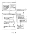
- FIG. 3 shows a block diagram indicating a life assessment procedure in the first embodiment according to the present invention
- FIG. 4 shows a block diagram indicating probabilistic creep- and fatigue-life assessment procedures with hardness analysis in the first embodiment according to the present invention
- FIG. 5 shows a matrix indicating a failure-unreliability function database in the first embodiment according to the present invention
- FIG. 6 shows a block diagram indicating a probabilistic creep-life assessment procedure with hardness analysis in the first embodiment according to the present invention
- FIG. 7 shows a block diagram indicating a probabilistic fatigue-life assessment procedure with replica analysis in the first embodiment according to the present invention
- FIG. 8 shows a block diagram indicating a probabilistic developed crack-affected life assessment procedure with embrittlement measurements in the first embodiment according to the present invention
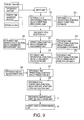
- FIG. 9 shows a block diagram of a second embodiment according to the present invention.
- FIG. 10 shows a block diagram indicating efficiency and operational-function decay-event tree breakdown in the second embodiment according to the present invention
- FIG. 11 shows a block diagram indicating an efficiency and operational-function decay parameter assessment procedure in the second embodiment according to the present invention
- FIG. 12 shows a block diagram indicating an efficiency and operational-function decay parameter assessment procedure with erosion-amount trend analysis in the second embodiment according to the present invention
- FIG. 13 shows a block diagram indicating an efficiency and operational-function decay parameter assessment procedure with creep deformation analysis in the second embodiment according to the present invention
- FIG. 14 shows a block diagram indicating efficiency and operational-function decay-event tree breakdown according to the present invention
- FIG. 15 shows a block diagram indicating an efficiency and operational-function decay parameter assessment procedure according to the present invention
- FIG. 16 shows a block diagram indicating an efficiency and operational-function decay parameter assessment procedure with oxide-layer thickness trend analysis according to the present invention.
- FIG. 17 shows a block diagram indicating an efficiency and operational-function decay parameter assessment procedure with hardness analysis to creep deformation and variation in oxide-layer thickness according to the present invention.
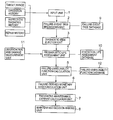
- FIG. 1 shows a block diagram of a first embodiment according to the present invention.
- a plant-maintenance apparatus incorporates an input unit 1 , a failure-event tree breakdown (FETB) unit 2 , a diagnostic item election (DIS) unit 3 , a probabilistic life assessment (PLA) unit 4 , a failure-unreliability function calculation (FUFC) unit 5 , a failure-derived monetary loss calculation (FDMLC) unit 6 , a preventive-maintenance expense calculation (PMEC) unit 7 and a maintenance decision-making (MDM) unit 8 .
- FETB failure-event tree breakdown
- DIS diagnostic item election
- PDA probabilistic life assessment
- FUFC failure-unreliability function calculation
- FDMLC failure-derived monetary loss calculation
- PMEC preventive-maintenance expense calculation
- MDM maintenance decision-making
- inspection-, diagnosis-, repair- and operation-history information such as, targets and ranges or a list of component parts of the plant equipment to be maintained, operation hours and operation-start/halt times, failures, damage, degradations and their indications.
- inspection-, diagnosis-, repair- and operation-history information such as, targets and ranges or a list of component parts of the plant equipment to be maintained, operation hours and operation-start/halt times, failures, damage, degradations and their indications.
- operations of the first embodiment against cracks to steam-turbine casing Disclosed below are operations of the first embodiment against cracks to steam-turbine casing.
- a steam-turbine casing could suffer fatigue damage accumulation due to thermo-mechanical stresses caused by variation in steam temperature and pressure during startup and shutdown, and also creep damage accumulation due to pressure and thermal stresses during steady operation. The creeps lead to cracks and deformation.
- the FETB unit 2 constructs a failure-event tree indicating causal sequences, such as shown in FIG. 2, based on data stored in a failure-event tree (FET) database 9 .
- Items for life assessments are cracks due to thermal fatigue of internal-casing corners, outer-casing pipings and welded sections about extraction ports of an outer-casing and creep deformation of horizontal joints. These four items are starting items (starting failure events) in the failure-event tree and selected as diagnostic items at the DIS unit 3 .
- the PLA unit 4 predicts unreliability of the starting items in the failure-event tree based on stored data from a statistical life assessment (SLA) database 10 and also measured data from a degradation and damage measurement (DDM) unit 11 .
- the PLA unit 4 comprises a temperature and stress analysis (TSA) unit 13 , a probabilistic temperature and stress fluctuation analysis (PTSFA) unit 14 and a probabilistic life calculation (PLC) unit 15 .
- the DDM unit 11 comprises a hardness measurement (HM) unit 16 , a replication and microstructural measurement (RMM) unit 17 and an embrittlement measurement (EM) unit 18 .
- the PLA unit 4 and the DDM unit 11 select material properties stored in the SLA database 10 in accordance with damage to or degradations of equipment or parts to be diagnosed.
- the TSA unit 13 calculates fluctuation of temperature and stress using the finite element method based on several factors indicating operational conditions such as fluid temperature, fluid pressure, flowrate, rotation speed and load, in steady operation. These input factors have been listed in tables as probability distributions that are statistical fluctuations obtained from the plant operation history.
- the probability distributions are converted by the PTSFA unit 14 into a temperature probability distribution Ps(T) with a temperature representative value Tss and a stress probability distributions Ps( ⁇ ) with a stress representative value ⁇ ss, respectively.
- the temperature and stress probability distributions may be obtained through simulation analysis with the finite element method using operational-condition-factor-probability-distribution parameters. Alternatively, the probability distributions may be obtained through Monte Carlo simulation with established relationship between the operational-condition factors and temperature and also stress based on analysis with the finite element method using experimental design.
- Creep damage is accumulated in component part materials as time elapses in steady operation.
- a creep rupture time tr(h) which can be used for creep-damage estimation based on temperature and stress, is expressed as below, with hardness HV, temperature T(° C.) and stress ⁇ (MPa)
- Parameters for probability distribution Pr is decided from a ratio of experimental value tr(h) to an estimated average value given by the expression (1).
- the probability distribution Pr is preferably logarithmic normal distribution or Weibull distribution.
- the HM unit 16 employs probability distribution with hardness HV 0 measured for sections degraded at the same temperature as the damaged sections for assessment of creeps.
- the probability distribution Ph is preferably logarithmic normal distribution.
- the TSA unit 13 calculates temperature variations ⁇ Tc, ⁇ Tw and ⁇ Th, rate of temperature changes dT/dt
- the elastic-to-plastic-repeated stress property is expressed as shown below at the SLA database 10 , given for each material with tensile strength and Young's modulus corresponding to measured hardness HV 0 .
- E(T) Young's modulus at an assessment temperature T
- a i is a constant (i: natural number)
- ⁇ B is tensile strength at assessment temperature (at room temperature or estimated from hardness)
- D 0 and “n” are constants.
- Conversion from stress to strain range is preferably performed with Neuber method or elastic-plastic infinite analysis.
- the probability distribution of the strain range is preferably performed with Monte Carlo simulation.
- the PLC unit 15 gives fatigue life with application of the total strain range and its probability distribution to the low-cycle fatigue life property.
- a low-cycle fatigue life N f is expressed at the SLA database 10 as shown below with a probability distribution P f .
- E(T) is Young's modulus at an assessment temperature T
- C e , ⁇ e, C p and ⁇ p are constants.
- the SLA database 10 and its probability distribution Pp to calculate the remaining life (duration and the number of times) in accordance with the damage accumulated so far and a future operation-expected pattern.
- FIG. 5 shows a list of unreliability allocated to the failure-event tree breakdown indicated in FIG. 2.
- unreliability F 01 is assigned to internal-casing corner-section thermal-fatigue cracks, one of the events for life assessments among the starting items in the failure-event tree breakdown.
- the subsequent events are assigned unreliability F(t), the rate of failures up to a given time “t” based on failure unreliability function in a failure-unreliability function (FUF) database 12 shown in FIG. 1.
- FUF failure-unreliability function
- the following technique can also be applied to the PLA unit 4 for directly calculating creep damage from hardness HV, as indicated in FIG. 6.
- the probability distribution given by experimental-data statistical processing with approximate expressions is applied to stochastic life-time calculation.
- tr( ⁇ , T, HV) is the creep rupture time, ⁇ stress and T temperature (K).
- Hardness HV, temperature T and stress ⁇ for materials of low initial transition density, such as CrMo-piping base materials, have the following relationship based on coarse-carbide modeling.
- HV Ce 1/2 /[ ⁇ T′ ⁇ ( ⁇ / E ( T ) So ) v exp( ⁇ Qx/T ) t/T ⁇ A +( Ce 1/2 /HVo ) 3 ] 1/3 (7)
- T′ temperature (° C.);
- HVo initial hardness
- Cc carbon content
- C B critical dissolving point
- E(T) Young's modulus at temperature T
- hardness HV, temperature T and stress ⁇ for materials of high initial transition density have the following relationship based on coarse-carbide modeling.
- HV 1/[1 /HVo 2 +Bt ( ⁇ / E ( T ) So ) v exp( ⁇ Qy/T )] 1/2 (8)
- Fatigue damage and the probability distribution are assessed as indicated in FIG. 7 with the maximum crack length a max and crack length density L, parameters given by measurements of fatigue crack distribution using a replica.
- n the number of repetition of strain application
- ⁇ t the total strain range
- T temperature
- HV hardness
- ⁇ p plastic strain range
- FIG. 8 is developed crack-affected life assessment employed by the PLA unit 4 .
- the EM unit 18 measures a temperature increase ⁇ FATT of each fractured-surface transition temperature FATT for equipment or parts, as embrittlement, with a known technique such as polarization measurements.
- the embrittlement is supplied to the SLA database 10 for giving fatigue-caused crack development property da/dN, creep-caused crack development property da/dt and fracture toughness as functions of ⁇ FATT, with probability distribution.
- the PLC unit 15 calculates stress intensity factor range ⁇ K or J-integration range ⁇ J in unsteady operation and stress intensity factor K or creep J-integration C* in steady operation, as fracture mechanics parameters, with calculation of fatigue-crack and creep-crack developments using the following expressions.
- the fracture toughness K Ic or J Ic that gives the limit acr is selected from the data in the SLA database 10 , as a function of ⁇ FATT.
- the FDMLC unit 6 calculates a cumulative cost Cr as shown below from unreliability Fij and cost Ci based on recovery costs (failure-derived monetary loss) assigned to events expected from these life-time assessments.
- the unreliability Fij if employing posterior-event unreliability, is required to be combined with unreliability of an event that occurs before each event expected from the life-time assessments.
- the cumulative cost Cr is sent to the PMEC unit 7 for calculation of the total preventive maintenance expenses based on preventive maintenance expense assigned to several preventive measures against those events.
- the total preventive maintenance expenses are sent to the MDM unit 8 for addition of depreciation and several maintenance fees to the total expenses.
- the expenses are expressed as a time-based function and compared with a risk cost.
- Maintenance timing is decided when the former is lower than the latter. If the plant is required to operate beyond the maintenance timing, life-time calculation is performed with switching the future operation patterns to select the pattern with the minimum risk cost among feasible operation patterns.
- the failure-event tree breakdown unit has the failure-event tree database constructed based on inspection and operation histories for the plant and also other plants, for tree breakdown starting with the life-assessment candidate items based on entered equipment parts and events.
- the life-assessment candidate items are employed by the diagnostic item selection unit as input data or starting events in the failure-event tree, thus all of the life-assessment candidate items and the items for risk calculations being covered.
- the first embodiment calculates the life probability distribution covering the occurrence of cracks to resultant damage to equipment parts as unreliability based on the probability variation in operational requirements including temperature and stress to the parts and material-life probability distribution while referring to the data stored in the statistical life assessment database.
- the first embodiment accurately provides unreliability of failure events expected due to aging and also failure events that will rarely occur but cause adverse effects in the failure-event tree breakdown.
- the first embodiment calculates unreliability based on the failure unreliability function on events in the failure-event tree breakdown using the entered data on parts and events and also the unreliability of items to be diagnosed based on the results given by the probabilistic life assessment unit, thus offering reliability assessments feasible to the actual plant conditions.
- the first embodiment can further adjust the order of failure-event tree breakdown and the failure unreliability function, thus achieving further accurate risk assessments in accordance with accumulated diagnostic records and data.
- the probabilistic life assessment database constructed as disclosed above allows selection of the material property required for probabilistic life assessments with probability-distribution parameters based on replica observations and/or embrittlement measurements, thus offering material-life probability-distribution property matching the actual equipment conditions.
- An original form of the failure-event tree is stored beforehand in the failure-event tree database 9 .
- the original form of the failure-event tree is made by expert engineers of the plant engineering by analyzing inspection histories and operation histories of plants similar to the plant to be maintained and by examining the correlation between the failure-events based on their technical experience.
- the FUFC unit 5 re-calculates the unreliability between the failure events (items).
- the re-calculated unreliability is stored in the failure-unreliability function database 12 .
- the FETB unit 2 modifies the original form of the failure-event tree (or the failure-event tree having been previously modified) stored in the failure-event tree database 9 on the basis of the re-calculation of the unreliability, in other words, the FETB unit 2 performs re-breakdown of the failure-event tree.
- the FETB unit 2 reverses the order of “steam leakage” and “casing erosion” in the failure-event tree shown in FIG. 2.
- the FETB unit 2 makes a new branch directly connecting “creep damage and fatigue crack development” to “casing failure” in the failure-event tree shown in FIG. 2.
- FIG. 9 shows a block diagram of a second embodiment according to the present invention. Elements shown in FIG. 9 the same as or analogous to the elements shown in FIG. 1 are referenced by the same numerals.
- an efficiency and operational-function decay-event tree breakdown (EOFDETB) unit 19 performs efficiency and operational-function decay-event tree breakdown starting with erosion of the initial-stage nozzle blade and creep deformation of a nozzle diaphragm, as shown in FIG. 10, based on data stored in an efficiency and operational-function decay-event tree (EOFDET) database 20 .
- EFDET efficiency and operational-function decay-event tree
- Erosion of the first-stage nozzle blade causes variation in the area of a nozzle throat and erosion of the shrouds and tenons of the moving-blades. Creep deformation of a nozzle diaphragm causes damage to the nozzle and a blade rotor wheel due to contact therewith. Either case results in increasing in an area of steam passages (including increasing in an area of the gap of the labyrinth seal), resulting in reduction in internal efficiency.
- FIG. 11 illustrates major procedures performed in the second embodiment shown in FIG. 9.
- EOFDPA efficiency and operational-function decay parameter assessment
- FIG. 12 Illustrated in FIG. 12 are assessments of erosion of the nozzle blades at the TA unit 29 .
- Statistical approximation to the relationship between each past operation time “t” and an erosion amount Er, and their probability distribution P Er are given by the TA unit 29 based on erosion amounts measured by an erosion-amount measurement (EAM) unit 31 through image processing, etc.
- EAM erosion-amount measurement
- the EOFDUFC unit 30 gives a life distribution P Er (t cr ) of the timing in which the erosion amount reaches the allowable limit in view of efficiency.
- the life distribution P Er (t cr ) is combined with life distributions based on other factors and sent to an efficiency and operational-function decay unreliability calculation (EOFDUC) unit 24 . These life distributions are allocated as unreliability to the efficiency and operational-function decay.
- EOFDUC efficiency and operational-function decay unreliability calculation
- FIG. 13 Illustrated in FIG. 13 are assessments based on temperature and stress analysis.
- ⁇ c C ( ⁇ / E ( T ))[1 ⁇ exp ⁇ r ( t m /t r mo ) ⁇ ]+ MCR ( tr )* t (16)
- E(T) Young's modulus at an assessment temperature
- tr function of creep fracture time ( ⁇ , T, HV);
- MCR minimum creep rate (function of tr);
- the EOFDUFC unit 30 calculates creep deformation dc with its probability distribution to give distribution P dc of the timing in which the creep deformation reaches the allowable limit in view of efficiency.
- the distribution P dc is combined with efficiency and operational function decay parameter distributions based on other factors and sent to the EOFDUC unit 24 . These distributions are allocated as unreliability to the efficiency and operational-function decay.
- An efficiency-and-operational-function decay parameter selection (EOFDPS) unit 33 in an efficiency and operational-function decay prediction (EOFDP) unit 27 sets parameters, such as, pressure and flow rate, for converting the efficiency and operational-function decay factors (loosened joints of steam pipes and sealing) to losses in steam flow based on the calculation at the EOFDUC unit 24 .
- the parameters are sent to an efficiency and operational-function calculation (SOFC) unit 34 to calculate the level of efficiency decay.
- SOFC operational-function calculation
- a total efficiency measurement unit 36 measures the total efficiency based on plant input and output while a partial efficiency measurement unit 37 measures partial efficiency based on signals from temperature, pressure and flow-rate sensors, etc.
- the measured data are sent to the EOFDP unit 27 in which an efficiency and operational-function modification (SOFM) unit 35 makes adjustments with comparison of the measured data and the results of efficiency and operational-function decay calculation, to establish efficiency- and operational-function decay assessments to the target equipment.
- SOFM efficiency and operational-function modification
- the cumulative cost is sent to the PMEC unit 7 for calculation of the total preventive maintenance expenses based on preventive maintenance expense assigned to several preventive measures against those events.
- the total preventive maintenance expenses are sent to the MDM unit 8 for addition of depreciation and several maintenance fees to the total expenses.
- the expenses are expressed as a time-based function and compared with a risk cost.
- Maintenance timing is decided when the former is lower than the latter. If the plant is required to operate beyond the decided maintenance timing, life-time calculation is performed with switching the future operation patterns to select the pattern with the minimum risk cost among feasible operation patterns.
- valve stems for major valves in a steam turbine as an efficiency and operational-function decay factor.
- valve stem is also suffered creep deformation and thus bent, which also results in operational stoppage.
- the efficiency and operational-function decay-event tree breakdown is then performed at the EOFDETB unit 19 starting with the efficiency and operational-function decay factor, based on data stored in the EOFDET database 20 .
- the results of two procedures performed by the TA unit 29 and also the TSA and PTSFA units 13 and 14 are sent to the EOFDUFC unit 30 for calculation of efficiency and operational-function decay unreliability function.
- FIG. 16 Illustrated in FIG. 16 are assessments of oxide-layer thickness at the TA unit 29 .
- Statistical approximation to the relationship between each past operation time “t” and an oxide-layer thickness dox, and their probability distribution P dox are given by the TA unit 29 based on oxide-layer thicknesses measured by an oxide-layer thickness measurement (OLTM) unit 38 through image processing, etc.
- OLTTM oxide-layer thickness measurement
- the EOFDUFC unit 30 gives a life distribution P dox (t cr ) of the timing in which the oxide-layer thickness “dox” reaches the limit for causing sticking.
- the life distribution P dox (t cr ) is combined with life distributions based on other factors and sent to the EOFDUC unit 24 . These life distributions are allocated as unreliability to the efficiency and operational-function decay.
- FIG. 17 Illustrated in FIG. 17 are assessments based on temperature and stress analysis.
- the temperature and stress representative values in steady operation are given by the TSA unit 13 and also the PTSFA unit 14 in the same way as the first embodiment.
- the hardness HV 0 measured by the HM unit 16 and its probability distribution Ph are applied to a creep-deformation property in the EOFDPA database 23 .
- the creep-deformation property is given by the expression (16) with probability distribution Pt.
- the oxide-layer thickness dox is given as follows.
- T temperature (K).
- the EOFDUFC unit 30 calculates creep deformation dc and oxide-layer thickness dox to the valve-opening bar with the probability distribution to give distributions P dc and Pox of the timing in which the creep deformation reaches the allowable limit in view of efficiency.
- the cumulative cost is sent to the PMEC unit 7 for calculation of the total preventive maintenance expenses based on preventive maintenance expense assigned to several preventive measures against those events.
- the total preventive maintenance expenses are sent to the MDM unit 8 for addition of depreciation and several maintenance fees to the total expenses.
- the expenses are expressed as a time-based function and compared with a risk cost function.
- Maintenance timing is decided when the former is lower than the latter. If the plant is required to operate beyond the decided maintenance timing, life-time calculation is performed with switching the future operation patterns to select the pattern with the minimum risk cost among feasible operation patterns.
- risks are expressed as costs against any predicted failure and operational function decay for plant equipment and compared with the preventive maintenance expenses, thus the second embodiment also offering a lowest-cost maintenance technique with the lowest risk probability.
- the efficiency and operational function decay assessment candidate items are employed by the diagnostic item selection unit, thus all of the efficiency and operational function decay assessment candidate items and the items for risk calculations being covered.
- the second embodiment gives quantitative unreliability function to efficiency and operational function decay factors, thus achieving accurate prediction of efficiency and operational function decay.
- An original form of the efficiency and operational-function decay-event tree is stored beforehand in the EOFDET database 20 .
- the original form of the decay-event tree is made by expert engineers of the plant engineering by analyzing inspection histories and operation histories of plants similar to the plant to be maintained and by examining the correlation between the decay-events based on their technical experience.
- the EOFDUC unit 24 re-calculates the decay unreliability between the decay events (items).
- the re-calculated decay unreliability is stored in the EOFDUC database 25 .
- the EOFDETB unit 19 modifies the original form of the decay-event tree (or the decay-event tree having been previously modified) stored in the EOFDET database 20 on the basis of the re-calculation of the decay-unreliability, in other words, the EOFDETB unit 19 performs re-breakdown of the decay-event tree.
- the EOFDETB unit 19 reverses the order of the items in the decay-event tree, and makes a new branch.
- the present invention combines life assessments and risk assessments, which have conventionally performed separately, thus achieving risk management against any failure events that lead to damage, efficiency decay and shutdown to plant equipment, the minimum management costs and also feasible plant operations with less losses.
Abstract
Description
- This application is based upon and claims the benefit of priority from the prior Japanese Patent Application No. 2002-106705, filed on Apr. 9, 2002, the entire contents of which are incorporated herein by reference.
- The present invention relates to risk-based plant-maintenance apparatus and method for maintaining plant equipment such as steam turbines for thermal power plants, against damage, efficiency decay and shutdown.
- Increase in the number of plants such as thermal power plants operating for long years has demanded maintenance at low cost but with no failures. Risk-based maintenance (RBM) has been recently introduced as one of the solutions to match the demands.
- A known RBM is to decide maintenance priority allocations based ranking in the order of combinations of classified plant-equipment failure rates and consequence of failure, such as, disclosed by Kihara et el., in Piping Technology, pages 76 to 79, issued in December, 2000.
- Classification of consequence of failure, however, requires experimental qualitative decision making, and hence has several drawbacks, for example, it does not necessarily involve quantitative evaluation.
- In addition, no one has proposed so far is an assessment technique, the combination of risk-based assessment and life, efficiency and operational-function diagnosis already employed in plant management.
- With the foregoing as background, it is an object of the present invention to provide a method and an apparatus for objectively and quantitatively deciding the optimum maintenance timing with by risk-based cost estimation covering all expected failure events based on prediction of damage, efficiency decay and shutdown.
- The present invention provides an apparatus for maintaining plant equipment, which includes: an input unit configured to receive data on inspection, diagnosis, repair and operation histories for equipment that constitute a plant; a failure-event tree breakdown unit configured to perform failure-event tree breakdown on failures to be expected for the equipment, in order to obtain a failure-event tree; a probabilistic life assessment unit configured to predict unreliability of a starting item in the failure-event tree breakdown; a failure-unreliability function calculation unit configured to calculate unreliability of each item in the failure-event tree; a failure-derived monetary loss calculation unit configured to multiply each unreliability and a cost of recovery from each failure event in the failure-event tree and accumulate results of the multiplication in accordance with the failure-event tree breakdown, thus obtaining a recovery cost; a preventive-maintenance expense calculation unit configured to calculate preventive maintenance expenses for preventing failure events; and an operation and maintenance decision-making unit configured to decide maintenance timing and technique through comparison between the recovery cost and the preventive maintenance expenses.
- Moreover, the present invention provides an apparatus for maintaining plant equipment, which includes: an input unit configured to receive data on inspection, diagnosis, repair and operation histories for equipment that constitute a plant; an efficiency and operational-function decay-event tree breakdown unit configured to perform efficiency and operational-function decay-event tree breakdown on efficiency and operational-function decay factors to be expected for the equipment, in order to obtain an efficiency and operational-function decay-event tree; an efficiency and operational-function decay parameter assessment unit configured to predict unreliability of a starting item in the efficiency and operational-function decay-event tree breakdown; an efficiency and operational-function decay unreliability calculation unit configured to calculate unreliability of each item in the efficiency and operational-function decay-event tree based on failure unreliability function; an efficiency and operational-function decay prediction unit configured to calculate efficiency and operational-function decay to be expected based on prediction by the efficiency and operational-function decay unreliability calculation unit; an efficiency and operational-function decay derived monetary loss calculation unit configured to multiply each unreliability and monetary loss due to efficiency and operational-function decay and a cost of recovery from the decay and accumulate results of the multiplication in accordance with the efficiency and operational-function decay-event tree breakdown; a preventive-maintenance expense calculation unit configured to calculate preventive maintenance expenses for preventing the efficiency and operational-function decay; and an operation and maintenance decision-making unit configured to decide maintenance timing and technique through comparison between the recovery cost and the preventive maintenance expenses.
- Furthermore, the present invention provides a method of maintaining plant equipment, which includes the steps of: receiving data on inspection, diagnosis, repair and operation histories for equipment that constitute a plant; performing failure-event tree breakdown on failures to be expected for the equipment, thereby obtaining a failure-event tree; predicting unreliability of a starting item in the failure-event tree breakdown; calculating unreliability of each item in the failure-event tree based on failure unreliability function; multiplying each unreliability and a cost of recovery from each failure event in the failure-event tree breakdown and accumulating results of the multiplication in accordance with the tree breakdown, thus obtaining a recovery cost; calculating preventive maintenance expenses for preventing failure events; and deciding maintenance timing and technique through comparison between the recovery cost and the preventive maintenance expenses.
- Moreover, the present invention provides a method of maintaining plant equipment, which includes the steps of: receiving data on inspection, diagnosis, repair and operation histories for equipment that constitute a plant; performing efficiency and operational-function decay event-tree breakdown on efficiency and operational-function decay factors to be expected for the equipment, thereby obtaining an efficiency and operational-function decay event-tree; predicting unreliability of at least one starting item in the efficiency and operational-function decay event-tree breakdown; calculating unreliability of each item in the efficiency and operational-function decay-event tree based on failure unreliability function; calculating efficiency and operational-function decay to be expected from the calculation based on the failure unreliability function; multiplying each unreliability and monetary loss due to efficiency and operational-function decay and a cost of recovery from the decay and accumulating results of the multiplication in accordance with the efficiency and operational-function decay-event tree breakdown; calculating preventive maintenance expenses for preventing the efficiency and operational-function decay; and deciding maintenance timing and technique through comparison between the recovery cost and the preventive maintenance expenses.
- FIG. 1 shows a block diagram of a first embodiment according to the present invention;
- FIG. 2 shows a block diagram indicating failure-event tree breakdown in the first embodiment according to the present invention;
- FIG. 3 shows a block diagram indicating a life assessment procedure in the first embodiment according to the present invention;
- FIG. 4 shows a block diagram indicating probabilistic creep- and fatigue-life assessment procedures with hardness analysis in the first embodiment according to the present invention;
- FIG. 5 shows a matrix indicating a failure-unreliability function database in the first embodiment according to the present invention;
- FIG. 6 shows a block diagram indicating a probabilistic creep-life assessment procedure with hardness analysis in the first embodiment according to the present invention;
- FIG. 7 shows a block diagram indicating a probabilistic fatigue-life assessment procedure with replica analysis in the first embodiment according to the present invention;
- FIG. 8 shows a block diagram indicating a probabilistic developed crack-affected life assessment procedure with embrittlement measurements in the first embodiment according to the present invention;
- FIG. 9 shows a block diagram of a second embodiment according to the present invention;
- FIG. 10 shows a block diagram indicating efficiency and operational-function decay-event tree breakdown in the second embodiment according to the present invention;
- FIG. 11 shows a block diagram indicating an efficiency and operational-function decay parameter assessment procedure in the second embodiment according to the present invention;
- FIG. 12 shows a block diagram indicating an efficiency and operational-function decay parameter assessment procedure with erosion-amount trend analysis in the second embodiment according to the present invention;
- FIG. 13 shows a block diagram indicating an efficiency and operational-function decay parameter assessment procedure with creep deformation analysis in the second embodiment according to the present invention;
- FIG. 14 shows a block diagram indicating efficiency and operational-function decay-event tree breakdown according to the present invention;
- FIG. 15 shows a block diagram indicating an efficiency and operational-function decay parameter assessment procedure according to the present invention;
- FIG. 16 shows a block diagram indicating an efficiency and operational-function decay parameter assessment procedure with oxide-layer thickness trend analysis according to the present invention; and
- FIG. 17 shows a block diagram indicating an efficiency and operational-function decay parameter assessment procedure with hardness analysis to creep deformation and variation in oxide-layer thickness according to the present invention.
- Several embodiments according to the present invention will be disclosed with reference to the attached drawings.
- FIG. 1 shows a block diagram of a first embodiment according to the present invention. A plant-maintenance apparatus incorporates an
input unit 1, a failure-event tree breakdown (FETB)unit 2, a diagnostic item election (DIS)unit 3, a probabilistic life assessment (PLA)unit 4, a failure-unreliability function calculation (FUFC)unit 5, a failure-derived monetary loss calculation (FDMLC)unit 6, a preventive-maintenance expense calculation (PMEC) unit 7 and a maintenance decision-making (MDM)unit 8. - Entered via the
input unit 1 are inspection-, diagnosis-, repair- and operation-history information, such as, targets and ranges or a list of component parts of the plant equipment to be maintained, operation hours and operation-start/halt times, failures, damage, degradations and their indications. Disclosed below are operations of the first embodiment against cracks to steam-turbine casing. - A steam-turbine casing could suffer fatigue damage accumulation due to thermo-mechanical stresses caused by variation in steam temperature and pressure during startup and shutdown, and also creep damage accumulation due to pressure and thermal stresses during steady operation. The creeps lead to cracks and deformation. Against such events, the FETB
unit 2 constructs a failure-event tree indicating causal sequences, such as shown in FIG. 2, based on data stored in a failure-event tree (FET)database 9. Items for life assessments are cracks due to thermal fatigue of internal-casing corners, outer-casing pipings and welded sections about extraction ports of an outer-casing and creep deformation of horizontal joints. These four items are starting items (starting failure events) in the failure-event tree and selected as diagnostic items at theDIS unit 3. - The
PLA unit 4 predicts unreliability of the starting items in the failure-event tree based on stored data from a statistical life assessment (SLA)database 10 and also measured data from a degradation and damage measurement (DDM)unit 11. As shown in FIG. 3, thePLA unit 4 comprises a temperature and stress analysis (TSA)unit 13, a probabilistic temperature and stress fluctuation analysis (PTSFA)unit 14 and a probabilistic life calculation (PLC)unit 15. Also as shown in FIG. 3, theDDM unit 11 comprises a hardness measurement (HM)unit 16, a replication and microstructural measurement (RMM)unit 17 and an embrittlement measurement (EM)unit 18. ThePLA unit 4 and theDDM unit 11 select material properties stored in theSLA database 10 in accordance with damage to or degradations of equipment or parts to be diagnosed. - Shown in FIG. 4 is a functional procedure for the
PLA unit 4. TheTSA unit 13 calculates fluctuation of temperature and stress using the finite element method based on several factors indicating operational conditions such as fluid temperature, fluid pressure, flowrate, rotation speed and load, in steady operation. These input factors have been listed in tables as probability distributions that are statistical fluctuations obtained from the plant operation history. The probability distributions are converted by thePTSFA unit 14 into a temperature probability distribution Ps(T) with a temperature representative value Tss and a stress probability distributions Ps(σ) with a stress representative value σss, respectively. The temperature and stress probability distributions may be obtained through simulation analysis with the finite element method using operational-condition-factor-probability-distribution parameters. Alternatively, the probability distributions may be obtained through Monte Carlo simulation with established relationship between the operational-condition factors and temperature and also stress based on analysis with the finite element method using experimental design. - Creep damage is accumulated in component part materials as time elapses in steady operation. A creep rupture time tr(h), which can be used for creep-damage estimation based on temperature and stress, is expressed as below, with hardness HV, temperature T(° C.) and stress σ(MPa)
- tr(h)=10[{A 0 +A 1 log(σ/HV)+A 2 (log(σ/HV))
2 +A 3 (log(σ/HV))}3 /(T+273)−C 0 ] (1) - Parameters for probability distribution Pr is decided from a ratio of experimental value tr(h) to an estimated average value given by the expression (1). The probability distribution Pr is preferably logarithmic normal distribution or Weibull distribution. The
HM unit 16 employs probability distribution with hardness HV0 measured for sections degraded at the same temperature as the damaged sections for assessment of creeps. The probability distribution Ph is preferably logarithmic normal distribution. - The
PLC unit 15 combines the probability distribution Ph for hardness with the probability distribution Pr for creep rupture time based on the expression (1) and further the temperature and stress probability distributions Ps(T) and Ps(σ). It further calculates probability distribution Pc of creep life tr(h) for equipment or parts and a ratio of the creep life tr(h) to the operation time “t” as creep damage Φc=∫dt/tr(σ, T, HV) with its probability distribution PΦc. - The combination of probability distributions is performed with integration of probability density function or Monte Carlo simulation.
- In unsteady operation, the
TSA unit 13 calculates temperature variations ΔTc, ΔTw and ΔTh, rate of temperature changes dT/dt|tc, dT/dt|tw and dT/dt|th and also their probability distributions PtdT and PtdTdt per typical operation patterns, such as, cold start, hot start and thermal start, from the operation history, with thermal analysis using statistical calculation and the infinite element method, etc., for thermal stress analysis - The
PTSFA unit 14 calculates stress variations Δσi(i=c, w, h), the peak-stress temperature Ti(i=c, w, h) and their probability distributions PtS and PtT corresponding to the respective operation patters from the analysis with same the techniques for the steady operation. - The
unit 14 also converts a stress range into the total strain range Δε(i=c, w, h) and its probability distribution Ptε using material elastic-to-plastic repeated stress property. - The elastic-to-plastic-repeated stress property is expressed as shown below at the
SLA database 10, given for each material with tensile strength and Young's modulus corresponding to measured hardness HV0. - Δεt =Δσ/E(T)+(Δσ/(D 0σB))l/n (2)
- E(T)=Σai T i−1
- where E(T) is Young's modulus at an assessment temperature T, “a i” is a constant (i: natural number), σB is tensile strength at assessment temperature (at room temperature or estimated from hardness) and D0 and “n” are constants.
- Conversion from stress to strain range is preferably performed with Neuber method or elastic-plastic infinite analysis. The probability distribution of the strain range is preferably performed with Monte Carlo simulation. The
PLC unit 15 gives fatigue life with application of the total strain range and its probability distribution to the low-cycle fatigue life property. A low-cycle fatigue life Nf is expressed at theSLA database 10 as shown below with a probability distribution Pf. - Δεt =C e/(Δσ/E)N f αe +C p N f αp (2)
- where E(T) is Young's modulus at an assessment temperature T, and C e, αe, Cp and αp are constants.
- For each startup pattern, the number of startups n i(i=c, w, h) and a ratio of fatigue life Nfi(i=c, w, h) to the total strain range Δεti(i=c, w, h) are added to each other to calculate fatigue damage Φf=Σni/Nfi and its probability distribution PΦf with probability parameter calculation or Monte Carlo simulation based on the probability distribution of fatigue life. The creep damage Φc and the fatigue damage Φf given as above are applied to creep-fatigue interaction property
- Φf+Φc =Dc(Φf,Φc) (4)
- in the
SLA database 10 and its probability distribution Pp to calculate the remaining life (duration and the number of times) in accordance with the damage accumulated so far and a future operation-expected pattern. The remaining life is expressed as the equivalent operation time teq=t+ΣBi*ni at thePLC unit 15, the accumulated probability distribution PL of the remaining life teq is employed as unreliability. - FIG. 5 shows a list of unreliability allocated to the failure-event tree breakdown indicated in FIG. 2. For example, unreliability F 01 is assigned to internal-casing corner-section thermal-fatigue cracks, one of the events for life assessments among the starting items in the failure-event tree breakdown. The subsequent events are assigned unreliability F(t), the rate of failures up to a given time “t” based on failure unreliability function in a failure-unreliability function (FUF)
database 12 shown in FIG. 1. - The following technique can also be applied to the
PLA unit 4 for directly calculating creep damage from hardness HV, as indicated in FIG. 6. The probability distribution given by experimental-data statistical processing with approximate expressions is applied to stochastic life-time calculation. - In detail, the creep damage based on the initial hardness HV 0 is calculated as follows:
- Φc =t/tr(σ, T, HV 0) (5)
- where tr(σ, T, HV) is the creep rupture time, σ stress and T temperature (K).
- The creep damage based on the present hardness HV of a creep-damaged section is calculated as follows:
- Φc =t/{t+tr(σ, T, HV)} (6)
- Hardness HV, temperature T and stress σ for materials of low initial transition density, such as CrMo-piping base materials, have the following relationship based on coarse-carbide modeling.
- HV=Ce 1/2 /[{T′ α(σ/E(T)So)v exp(−Qx/T)t/T}A+(Ce 1/2 /HVo)3]1/3 (7)
- where
- Ce=Cc−C B, E(T)=ΣaiTi−1;
- T′: temperature (° C.);
- A, v, α, So and Qx: constants;
- HVo: initial hardness;
- Cc: carbon content;
- C B: critical dissolving point;
- E(T): Young's modulus at temperature T; and
- a i: constant (i: natural number)
- Moreover, hardness HV, temperature T and stress σ for materials of high initial transition density, such as CrMo HAZ-materials and CrMoV materials, have the following relationship based on coarse-carbide modeling.
- HV=1/[1/HVo 2 +Bt(σ/E(T)So)v exp(−Qy/T)]1/2 (8)
- where B and Qy are constants.
- Fatigue damage and the probability distribution are assessed as indicated in FIG. 7 with the maximum crack length a max and crack length density L, parameters given by measurements of fatigue crack distribution using a replica.
- The maximum crack length a max and the fatigue damage Φf=n/Nf have the following relationship:
- a max =E exp(Fn/N f) (9)
- where E and F are constants.
- The crack length density L and the fatigue damage Φ f=n/Nf have the following relationship:

- μ Le=D1Δεp ml
- where
- n: the number of repetition of strain application;
- N f(Δεt, T, HV): the number of fatigue damage;
- Δε t: the total strain range;
- T: temperature;
- HV: hardness;
- Δε p: plastic strain range; and
- lc, σ′ Le, D1 and m1: constants.
- Indicated FIG. 8 is developed crack-affected life assessment employed by the
PLA unit 4. TheEM unit 18 measures a temperature increase ΔFATT of each fractured-surface transition temperature FATT for equipment or parts, as embrittlement, with a known technique such as polarization measurements. The embrittlement is supplied to theSLA database 10 for giving fatigue-caused crack development property da/dN, creep-caused crack development property da/dt and fracture toughness as functions of ΔFATT, with probability distribution. Based on the calculations at the TSA andPTSFA units PLC unit 15 calculates stress intensity factor range ΔK or J-integration range ΔJ in unsteady operation and stress intensity factor K or creep J-integration C* in steady operation, as fracture mechanics parameters, with calculation of fatigue-crack and creep-crack developments using the following expressions. - fatigue-crack developments:
- a=∫da/dN·dN=∫CΔK m da (11)
- or
- a=∫da/dN·dN=∫C′ΔJ m′ da (12)
- creep-crack developments:
- a=∫da/dt·dt=∫DK n dt (13)
- or
- a=∫da/dt·dt=∫D′C* n′ dt (14)
- These calculations are performed in accordance with the operation patterns for obtaining the probability distribution through Monte Carlo simulation.
- The life time is decided when the crack length reaches the limit acr=f(K Ic or JIc). The fracture toughness KIc or JIc that gives the limit acr is selected from the data in the
SLA database 10, as a function of ΔFATT. - The
FDMLC unit 6 calculates a cumulative cost Cr as shown below from unreliability Fij and cost Ci based on recovery costs (failure-derived monetary loss) assigned to events expected from these life-time assessments. The unreliability Fij, if employing posterior-event unreliability, is required to be combined with unreliability of an event that occurs before each event expected from the life-time assessments. - Cr=σ( . . . Fhi·Fij)Ci (15)
- The cumulative cost Cr is sent to the PMEC unit 7 for calculation of the total preventive maintenance expenses based on preventive maintenance expense assigned to several preventive measures against those events.
- The total preventive maintenance expenses are sent to the
MDM unit 8 for addition of depreciation and several maintenance fees to the total expenses. The expenses are expressed as a time-based function and compared with a risk cost. Maintenance timing is decided when the former is lower than the latter. If the plant is required to operate beyond the maintenance timing, life-time calculation is performed with switching the future operation patterns to select the pattern with the minimum risk cost among feasible operation patterns. - As disclosed in detail, risks are expressed as costs against any failure events to plant equipment expected based on life-time prediction and compared with the preventive maintenance expenses, thus the first embodiment offering a lowest-cost maintenance technique with the lowest risk possibility, and also the operation pattern that allows plant operation up to a desired timing with the least risk. Moreover, the failure-event tree breakdown unit has the failure-event tree database constructed based on inspection and operation histories for the plant and also other plants, for tree breakdown starting with the life-assessment candidate items based on entered equipment parts and events. The life-assessment candidate items are employed by the diagnostic item selection unit as input data or starting events in the failure-event tree, thus all of the life-assessment candidate items and the items for risk calculations being covered.
- Moreover, the first embodiment calculates the life probability distribution covering the occurrence of cracks to resultant damage to equipment parts as unreliability based on the probability variation in operational requirements including temperature and stress to the parts and material-life probability distribution while referring to the data stored in the statistical life assessment database. Thus, the first embodiment accurately provides unreliability of failure events expected due to aging and also failure events that will rarely occur but cause adverse effects in the failure-event tree breakdown. Furthermore, the first embodiment calculates unreliability based on the failure unreliability function on events in the failure-event tree breakdown using the entered data on parts and events and also the unreliability of items to be diagnosed based on the results given by the probabilistic life assessment unit, thus offering reliability assessments feasible to the actual plant conditions.
- The first embodiment can further adjust the order of failure-event tree breakdown and the failure unreliability function, thus achieving further accurate risk assessments in accordance with accumulated diagnostic records and data. Moreover, the probabilistic life assessment database constructed as disclosed above allows selection of the material property required for probabilistic life assessments with probability-distribution parameters based on replica observations and/or embrittlement measurements, thus offering material-life probability-distribution property matching the actual equipment conditions.
- An original form of the failure-event tree is stored beforehand in the failure-
event tree database 9. The original form of the failure-event tree is made by expert engineers of the plant engineering by analyzing inspection histories and operation histories of plants similar to the plant to be maintained and by examining the correlation between the failure-events based on their technical experience. When inspection data on the plant to be maintained and/or on other similar plants and operation histories of the plants are renewed, theFUFC unit 5 re-calculates the unreliability between the failure events (items). The re-calculated unreliability is stored in the failure-unreliability function database 12. In addition, theFETB unit 2 modifies the original form of the failure-event tree (or the failure-event tree having been previously modified) stored in the failure-event tree database 9 on the basis of the re-calculation of the unreliability, in other words, theFETB unit 2 performs re-breakdown of the failure-event tree. In detail, in the event that the unreliability of “casing erosion” with respect to “creep damage and fatigue crack development” becomes higher than the unreliability of “steam leakage” with respect to “creep damage and fatigue crack development,” theFETB unit 2 reverses the order of “steam leakage” and “casing erosion” in the failure-event tree shown in FIG. 2. In addition, in the event that “casing failure” is occurred after the occurrence of “creep damage and fatigue crack development” without occurring “steam leakage” and “casing erosion”, theFETB unit 2 makes a new branch directly connecting “creep damage and fatigue crack development” to “casing failure” in the failure-event tree shown in FIG. 2. - FIG. 9 shows a block diagram of a second embodiment according to the present invention. Elements shown in FIG. 9 the same as or analogous to the elements shown in FIG. 1 are referenced by the same numerals.
- Disclosed below are operations of the second embodiment against decay in efficiency and operational function, not damage to equipment parts, for life assessments.
- Entered via the
input unit 1 are targets and ranges of assessments, operation-, inspection-, diagnosis- and repair-history information, etc. - Against efficiency-decay events on a steam-turbine nozzle, an efficiency and operational-function decay-event tree breakdown (EOFDETB)
unit 19 performs efficiency and operational-function decay-event tree breakdown starting with erosion of the initial-stage nozzle blade and creep deformation of a nozzle diaphragm, as shown in FIG. 10, based on data stored in an efficiency and operational-function decay-event tree (EOFDET)database 20. - Erosion of the first-stage nozzle blade causes variation in the area of a nozzle throat and erosion of the shrouds and tenons of the moving-blades. Creep deformation of a nozzle diaphragm causes damage to the nozzle and a blade rotor wheel due to contact therewith. Either case results in increasing in an area of steam passages (including increasing in an area of the gap of the labyrinth seal), resulting in reduction in internal efficiency.
- These events are subjected to the efficiency and operational-function decay-event tree breakdown at the
EOFDETB unit 19. The four items discussed above are the starting items in the tree breakdown and selected by theDIS unit 3 as the items to diagnosed. - FIG. 11 illustrates major procedures performed in the second embodiment shown in FIG. 9.
- In an efficiency and operational-function decay parameter assessment (EOFDPA)
unit 21, the results of two procedures performed by a trend analysis (TA)unit 29 and also the TSA andPTSFA units unit 30. - Illustrated in FIG. 12 are assessments of erosion of the nozzle blades at the
TA unit 29. Statistical approximation to the relationship between each past operation time “t” and an erosion amount Er, and their probability distribution PEr are given by theTA unit 29 based on erosion amounts measured by an erosion-amount measurement (EAM)unit 31 through image processing, etc. - The
EOFDUFC unit 30 gives a life distribution PEr(tcr) of the timing in which the erosion amount reaches the allowable limit in view of efficiency. - The life distribution P Er(tcr) is combined with life distributions based on other factors and sent to an efficiency and operational-function decay unreliability calculation (EOFDUC)
unit 24. These life distributions are allocated as unreliability to the efficiency and operational-function decay. - Illustrated in FIG. 13 are assessments based on temperature and stress analysis.
- In detail, the temperature and stress representative values in steady operation are given by the
TSA unit 13 and also thePTSFA unit 14 in the same way as the first embodiment. - Along with this, the hardness HV 0 measured by the
HM unit 16 and its probability distribution Ph are applied to a creep-deformation property in an efficiency and operational-function decay parameter assessment (EOFDPA)database 23. - The creep-deformation property is expressed as follows and given with probability distribution Pr.
- εc =C(σ/E(T))[1−exp{−r(t m /t r mo)}]+MCR(tr)*t (16)
- where
- ε c: creep strain (%);
- E(T): Young's modulus at an assessment temperature;
- σ: stress;
- tr: function of creep fracture time (σ, T, HV);
- MCR: minimum creep rate (function of tr);
- t: time; and
- C, r, m and mo: constants.
- The results of calculation at the
PTSFA unit 14 are applied to the expression (16). - The
EOFDUFC unit 30 calculates creep deformation dc with its probability distribution to give distribution Pdc of the timing in which the creep deformation reaches the allowable limit in view of efficiency. - The distribution P dc is combined with efficiency and operational function decay parameter distributions based on other factors and sent to the
EOFDUC unit 24. These distributions are allocated as unreliability to the efficiency and operational-function decay. - An efficiency-and-operational-function decay parameter selection (EOFDPS)
unit 33 in an efficiency and operational-function decay prediction (EOFDP)unit 27 sets parameters, such as, pressure and flow rate, for converting the efficiency and operational-function decay factors (loosened joints of steam pipes and sealing) to losses in steam flow based on the calculation at theEOFDUC unit 24. - The parameters are sent to an efficiency and operational-function calculation (SOFC)
unit 34 to calculate the level of efficiency decay. - In an efficiency-
decay measurement unit 26, a totalefficiency measurement unit 36 measures the total efficiency based on plant input and output while a partialefficiency measurement unit 37 measures partial efficiency based on signals from temperature, pressure and flow-rate sensors, etc. - The measured data are sent to the
EOFDP unit 27 in which an efficiency and operational-function modification (SOFM)unit 35 makes adjustments with comparison of the measured data and the results of efficiency and operational-function decay calculation, to establish efficiency- and operational-function decay assessments to the target equipment. - Monetary losses expected from the efficiency and operational-function decay assessments and recovery costs against the efficiency and operational-function decay factors are sent to an efficiency and operational-function decay derived monetary loss calculation (EOFDDMLC)
unit 28 shown in FIG. 9, for calculation of a cumulative cost, in the same as the first embodiment. - The cumulative cost is sent to the PMEC unit 7 for calculation of the total preventive maintenance expenses based on preventive maintenance expense assigned to several preventive measures against those events.
- The total preventive maintenance expenses are sent to the
MDM unit 8 for addition of depreciation and several maintenance fees to the total expenses. The expenses are expressed as a time-based function and compared with a risk cost. Maintenance timing is decided when the former is lower than the latter. If the plant is required to operate beyond the decided maintenance timing, life-time calculation is performed with switching the future operation patterns to select the pattern with the minimum risk cost among feasible operation patterns. - Discussed below is operational stoppage of valve stems for major valves in a steam turbine as an efficiency and operational-function decay factor.
- As indicated in FIG. 14, steam-oxide layer is gradually formed in the gap between a valve stem and a valve casing as plant operation continues, which causes sticking due to decrease in the gap, thus resulting in operational stoppage.
- The valve stem is also suffered creep deformation and thus bent, which also results in operational stoppage.
- The efficiency and operational-function decay-event tree breakdown is then performed at the
EOFDETB unit 19 starting with the efficiency and operational-function decay factor, based on data stored in theEOFDET database 20. - In the
EOFDPA unit 21, the results of two procedures performed by theTA unit 29 and also the TSA andPTSFA units EOFDUFC unit 30 for calculation of efficiency and operational-function decay unreliability function. - Illustrated in FIG. 16 are assessments of oxide-layer thickness at the
TA unit 29. Statistical approximation to the relationship between each past operation time “t” and an oxide-layer thickness dox, and their probability distribution Pdox are given by theTA unit 29 based on oxide-layer thicknesses measured by an oxide-layer thickness measurement (OLTM)unit 38 through image processing, etc. - The
EOFDUFC unit 30 gives a life distribution Pdox(tcr) of the timing in which the oxide-layer thickness “dox” reaches the limit for causing sticking. - The life distribution P dox(tcr) is combined with life distributions based on other factors and sent to the
EOFDUC unit 24. These life distributions are allocated as unreliability to the efficiency and operational-function decay. - Illustrated in FIG. 17 are assessments based on temperature and stress analysis. In detail, the temperature and stress representative values in steady operation are given by the
TSA unit 13 and also thePTSFA unit 14 in the same way as the first embodiment. Along with this, the hardness HV0 measured by theHM unit 16 and its probability distribution Ph are applied to a creep-deformation property in theEOFDPA database 23. The creep-deformation property is given by the expression (16) with probability distribution Pt. - The oxide-layer thickness dox is given as follows.
- dox=Dt β exp(−Q/kT) (17)
- where
- t: time;
- Q: activating energy;
- k: Boltzmann constant;
- T: temperature (K); and
- D, β: constants.
- The results of calculation at the
PTSFA unit 14 are applied to the expressions (9) and (10). - The
EOFDUFC unit 30 calculates creep deformation dc and oxide-layer thickness dox to the valve-opening bar with the probability distribution to give distributions Pdc and Pox of the timing in which the creep deformation reaches the allowable limit in view of efficiency. - The distributions Pdc and Pox are combined with each other and sent to the
EOFDUC unit 24. These distributions are assigned as unreliability which reads to the condition in that valve-opening bar cannot operate properly. - Monetary losses due to failures expected from the efficiency and operational-function decay assessments and recovery costs are sent to the
EOFDDMLC unit 28 shown in FIG. 9, for calculation of cumulative cost, in the same as the first embodiment. - The cumulative cost is sent to the PMEC unit 7 for calculation of the total preventive maintenance expenses based on preventive maintenance expense assigned to several preventive measures against those events.
- The total preventive maintenance expenses are sent to the
MDM unit 8 for addition of depreciation and several maintenance fees to the total expenses. The expenses are expressed as a time-based function and compared with a risk cost function. Maintenance timing is decided when the former is lower than the latter. If the plant is required to operate beyond the decided maintenance timing, life-time calculation is performed with switching the future operation patterns to select the pattern with the minimum risk cost among feasible operation patterns. - As disclosed in detail, risks are expressed as costs against any predicted failure and operational function decay for plant equipment and compared with the preventive maintenance expenses, thus the second embodiment also offering a lowest-cost maintenance technique with the lowest risk probability.
- Moreover, the efficiency and operational function decay assessment candidate items are employed by the diagnostic item selection unit, thus all of the efficiency and operational function decay assessment candidate items and the items for risk calculations being covered.
- Furthermore, the second embodiment gives quantitative unreliability function to efficiency and operational function decay factors, thus achieving accurate prediction of efficiency and operational function decay.
- An original form of the efficiency and operational-function decay-event tree is stored beforehand in the
EOFDET database 20. The original form of the decay-event tree is made by expert engineers of the plant engineering by analyzing inspection histories and operation histories of plants similar to the plant to be maintained and by examining the correlation between the decay-events based on their technical experience. When inspection data on the plant to be maintained and/or on other similar plants and operation histories of the plants are renewed, theEOFDUC unit 24 re-calculates the decay unreliability between the decay events (items). The re-calculated decay unreliability is stored in theEOFDUC database 25. In addition, theEOFDETB unit 19 modifies the original form of the decay-event tree (or the decay-event tree having been previously modified) stored in theEOFDET database 20 on the basis of the re-calculation of the decay-unreliability, in other words, theEOFDETB unit 19 performs re-breakdown of the decay-event tree. In detail, as described in the first embodiment, theEOFDETB unit 19 reverses the order of the items in the decay-event tree, and makes a new branch. - As disclosed above in detail, the present invention combines life assessments and risk assessments, which have conventionally performed separately, thus achieving risk management against any failure events that lead to damage, efficiency decay and shutdown to plant equipment, the minimum management costs and also feasible plant operations with less losses.
Claims (12)
Applications Claiming Priority (2)
| Application Number | Priority Date | Filing Date | Title |
|---|---|---|---|
| JP2002106705A JP4058289B2 (en) | 2002-04-09 | 2002-04-09 | Plant equipment life diagnosis / maintenance management method and apparatus |
| JP2002-106705 | 2002-04-09 |
Publications (2)
| Publication Number | Publication Date |
|---|---|
| US20030191606A1 true US20030191606A1 (en) | 2003-10-09 |
| US6928391B2 US6928391B2 (en) | 2005-08-09 |
Family
ID=28449927
Family Applications (1)
| Application Number | Title | Priority Date | Filing Date |
|---|---|---|---|
| US10/409,278 Expired - Fee Related US6928391B2 (en) | 2002-04-09 | 2003-04-09 | Plant maintenance method and apparatus |
Country Status (5)
| Country | Link |
|---|---|
| US (1) | US6928391B2 (en) |
| EP (1) | EP1353284A3 (en) |
| JP (1) | JP4058289B2 (en) |
| AU (1) | AU2003203598B2 (en) |
| MX (1) | MXPA03003044A (en) |
Cited By (32)
| Publication number | Priority date | Publication date | Assignee | Title |
|---|---|---|---|---|
| US20050102119A1 (en) * | 2003-11-11 | 2005-05-12 | International Business Machines Corporation | Automated knowledge system for equipment repair based on component failure history |
| US20070050221A1 (en) * | 2005-08-29 | 2007-03-01 | Abtar Singh | Dispatch management model |
| US20100023359A1 (en) * | 2008-07-23 | 2010-01-28 | Accenture Global Services Gmbh | Integrated prouction loss management |
| US20100036702A1 (en) * | 2008-08-08 | 2010-02-11 | Pinnacleais, Llc | Asset Management Systems and Methods |
| US7689873B1 (en) * | 2005-09-19 | 2010-03-30 | Google Inc. | Systems and methods for prioritizing error notification |
| US20100114836A1 (en) * | 2008-10-17 | 2010-05-06 | Oracle International Corporation | Data decay management |
| CN102052104A (en) * | 2009-10-30 | 2011-05-11 | 通用电气公司 | Turbine life assessment and inspection system and methods |
| CN102539129A (en) * | 2010-11-30 | 2012-07-04 | 通用电气公司 | Turbine performance diagnostic system and methods |
| US20130031424A1 (en) * | 2011-07-27 | 2013-01-31 | Oracle International Corporation | Proactive and adaptive cloud monitoring |
| US8964338B2 (en) | 2012-01-11 | 2015-02-24 | Emerson Climate Technologies, Inc. | System and method for compressor motor protection |
| US8974573B2 (en) | 2004-08-11 | 2015-03-10 | Emerson Climate Technologies, Inc. | Method and apparatus for monitoring a refrigeration-cycle system |
| US9121407B2 (en) | 2004-04-27 | 2015-09-01 | Emerson Climate Technologies, Inc. | Compressor diagnostic and protection system and method |
| US9140728B2 (en) | 2007-11-02 | 2015-09-22 | Emerson Climate Technologies, Inc. | Compressor sensor module |
| US20150369253A1 (en) * | 2014-06-20 | 2015-12-24 | Dell Products, Lp | System and Method for Improving Fan Life in an Information Handling System |
| US9285802B2 (en) | 2011-02-28 | 2016-03-15 | Emerson Electric Co. | Residential solutions HVAC monitoring and diagnosis |
| US9310439B2 (en) | 2012-09-25 | 2016-04-12 | Emerson Climate Technologies, Inc. | Compressor having a control and diagnostic module |
| US9310094B2 (en) | 2007-07-30 | 2016-04-12 | Emerson Climate Technologies, Inc. | Portable method and apparatus for monitoring refrigerant-cycle systems |
| US9551504B2 (en) | 2013-03-15 | 2017-01-24 | Emerson Electric Co. | HVAC system remote monitoring and diagnosis |
| US9638436B2 (en) | 2013-03-15 | 2017-05-02 | Emerson Electric Co. | HVAC system remote monitoring and diagnosis |
| US9765979B2 (en) | 2013-04-05 | 2017-09-19 | Emerson Climate Technologies, Inc. | Heat-pump system with refrigerant charge diagnostics |
| US9803902B2 (en) | 2013-03-15 | 2017-10-31 | Emerson Climate Technologies, Inc. | System for refrigerant charge verification using two condenser coil temperatures |
| US9823632B2 (en) | 2006-09-07 | 2017-11-21 | Emerson Climate Technologies, Inc. | Compressor data module |
| US9885507B2 (en) | 2006-07-19 | 2018-02-06 | Emerson Climate Technologies, Inc. | Protection and diagnostic module for a refrigeration system |
| CN109154811A (en) * | 2016-06-13 | 2019-01-04 | Abb瑞士股份有限公司 | Method for assessing the health status of industrial equipment |
| CN110033128A (en) * | 2019-03-18 | 2019-07-19 | 西安科技大学 | Drag conveyor loaded self-adaptive prediction technique based on limited Boltzmann machine |
| CN110482815A (en) * | 2019-07-23 | 2019-11-22 | 湖南九层台环境科技有限公司 | A kind of rural area village septic tank handles O&M expense low level management system |
| US10504062B2 (en) * | 2013-01-28 | 2019-12-10 | Mike Wilson | Disaster mitigation and recovery system and method |
| CN111105847A (en) * | 2019-12-20 | 2020-05-05 | 广东石油化工学院 | Cr-Ni-Fe alloy creep damage early stage and failure critical state judgment and early warning method based on magnetic signal |
| CN112668794A (en) * | 2020-12-31 | 2021-04-16 | 南京航空航天大学 | Maintenance optimization method for aircraft engine under uncertain life prediction information |
| EP3855019A1 (en) * | 2020-01-23 | 2021-07-28 | General Electric Company | System and method for operating a wind turbine |
| US11181897B2 (en) * | 2018-03-22 | 2021-11-23 | Mitsubishi Heavy Industries, Ltd. | Damage probability calculation device and damage probability calculation method |
| WO2022077204A1 (en) * | 2020-10-13 | 2022-04-21 | 华东理工大学 | Time-dependent local stress-strain method and tool software for high-temperature structural strength and service life analysis |
Families Citing this family (31)
| Publication number | Priority date | Publication date | Assignee | Title |
|---|---|---|---|---|
| JP2003303014A (en) * | 2002-04-09 | 2003-10-24 | Toshiba Corp | Maintenance management method for plant equipment and device |
| JP4141937B2 (en) * | 2003-11-10 | 2008-08-27 | 株式会社日立製作所 | Data storage method, data storage program, and computer-readable recording medium |
| US7769568B2 (en) * | 2004-07-09 | 2010-08-03 | The United States Of America As Represented By The Secretary Of The Army | Employing a dynamic lifecycle condition index (CI) to accommodate for changes in the expected service life of an item based on observance of the item and select extrinsic factors |
| US7058544B2 (en) * | 2004-07-09 | 2006-06-06 | The United States Of America As Represented By The Secretary Of The Army | Knowledge-based condition survey inspection (KBCSI) framework and procedure |
| JP2006125299A (en) * | 2004-10-28 | 2006-05-18 | Toshiba Corp | Device for evaluating remaining life of steam turbine rotor, method of evaluating remaining life of steam turbine rotor, rotor blade and steam turbine |
| US20060111871A1 (en) * | 2004-11-19 | 2006-05-25 | Winston Howard A | Method of and system for representing unscheduled events in a service plan |
| US20060184383A1 (en) * | 2005-02-14 | 2006-08-17 | Domestic Auto Experts | Methods and systems for pricing parts and components |
| JP2006252136A (en) * | 2005-03-10 | 2006-09-21 | Tokyo Electric Power Co Inc:The | Maintenance and management support method for breakwater covered with wave dissipating block and program therefor |
| JP4699344B2 (en) * | 2005-12-07 | 2011-06-08 | 三菱重工業株式会社 | Equipment maintenance planning method for plant equipment |
| JP4915210B2 (en) * | 2005-12-27 | 2012-04-11 | 東京電力株式会社 | Information processing method and apparatus |
| US7467045B2 (en) * | 2006-01-20 | 2008-12-16 | Schlumberger Technology Corporation | Method for assessment of uncertainty and risk |
| JP4885008B2 (en) * | 2007-02-23 | 2012-02-29 | 三菱重工業株式会社 | Maintenance planning method |
| US7715991B2 (en) * | 2007-05-17 | 2010-05-11 | General Electric Company | Systems and methods for monitoring energy system components |
| JP4919875B2 (en) * | 2007-05-30 | 2012-04-18 | 株式会社東芝 | Structure stress analysis method and apparatus |
| US7634383B2 (en) * | 2007-07-31 | 2009-12-15 | Northrop Grumman Corporation | Prognosis adaptation method |
| US7822577B2 (en) * | 2007-08-15 | 2010-10-26 | General Electric Company | Methods and systems to develop an experience-based probabilistic lifing process |
| US9063541B2 (en) * | 2008-06-20 | 2015-06-23 | Honeywell International Inc. | Method and means for tracking corrosion-related plant operation costs |
| KR101135168B1 (en) * | 2009-08-07 | 2012-04-16 | 한국전력공사 | Method and system for inspecting creep and thinned damage in heat exchanger steam tube |
| US8660875B2 (en) * | 2009-11-02 | 2014-02-25 | Applied Materials, Inc. | Automated corrective and predictive maintenance system |
| JP2013117754A (en) * | 2011-12-01 | 2013-06-13 | Ihi Corp | Risk assessment apparatus and risk assessment program |
| WO2013191596A1 (en) * | 2012-06-19 | 2013-12-27 | Gkn Aerospace Sweden Ab | Method for generating a simplified calculation model and method for predicting life consumption of a component |
| JP5870910B2 (en) * | 2012-12-20 | 2016-03-01 | Jfeスチール株式会社 | Drum deterioration evaluation method and drum deterioration recovery method of drum mixer |
| JP6104643B2 (en) | 2013-03-04 | 2017-03-29 | 三菱重工業株式会社 | Operation plan creation device, operation plan creation method, and operation plan creation program |
| US9200984B2 (en) | 2013-10-11 | 2015-12-01 | Solar Turbines Incorporated | Condition based lifing of gas turbine engine components |
| KR101526313B1 (en) * | 2013-11-20 | 2015-06-09 | 국립대학법인 울산과학기술대학교 산학협력단 | Method for predicting fatigue life |
| US20180253087A1 (en) * | 2017-03-06 | 2018-09-06 | General Electric Company | Scheduling maintenance to reduce degradation of a power generation system |
| US10597988B2 (en) | 2017-11-28 | 2020-03-24 | Saudi Arabian Oil Company | Systems and methods for operating downhole inflow control valves |
| CN111386540B (en) | 2017-11-29 | 2023-07-21 | 三菱电机株式会社 | Maintenance planning system and maintenance planning method |
| JP2020046814A (en) * | 2018-09-18 | 2020-03-26 | 東電設計株式会社 | Operation support method, operation support device, and operation support program |
| WO2020066197A1 (en) * | 2018-09-27 | 2020-04-02 | 株式会社テイエルブイ | Operating cost assessment method and operating cost assessment program |
| WO2023058086A1 (en) * | 2021-10-04 | 2023-04-13 | 日本電信電話株式会社 | Hydrogen embrittlement risk assessment method and device therefor |
Citations (2)
| Publication number | Priority date | Publication date | Assignee | Title |
|---|---|---|---|---|
| US6505145B1 (en) * | 1999-02-22 | 2003-01-07 | Northeast Equipment Inc. | Apparatus and method for monitoring and maintaining plant equipment |
| US6618692B2 (en) * | 2000-09-20 | 2003-09-09 | Hitachi, Ltd. | Remote diagnostic system and method for semiconductor manufacturing equipment |
Family Cites Families (14)
| Publication number | Priority date | Publication date | Assignee | Title |
|---|---|---|---|---|
| JPH0660918B2 (en) * | 1988-02-15 | 1994-08-10 | 沖ユニシス株式会社 | Electronic device self-diagnosis device |
| JP2642438B2 (en) * | 1988-09-05 | 1997-08-20 | 株式会社東芝 | Plant equipment maintenance management support device |
| US5311562A (en) | 1992-12-01 | 1994-05-10 | Westinghouse Electric Corp. | Plant maintenance with predictive diagnostics |
| US5648919A (en) | 1993-02-15 | 1997-07-15 | Babcock-Hitachi Kabushiki Kaisha | Maintenance systems for degradation of plant component parts |
| JP3353441B2 (en) * | 1994-02-22 | 2002-12-03 | 三菱電機株式会社 | Numerical control device and its failure diagnosis system |
| JP3392526B2 (en) * | 1994-07-29 | 2003-03-31 | 株式会社東芝 | Equipment maintenance management support equipment |
| JPH08115108A (en) * | 1994-10-17 | 1996-05-07 | Hitachi Ltd | Ranking display device for preventive maintenance equipment |
| JPH0933684A (en) * | 1995-07-17 | 1997-02-07 | Hitachi Ltd | Method and device for preventive maintenance |
| JPH0954613A (en) * | 1995-08-11 | 1997-02-25 | Toshiba Corp | Plant facility monitor device |
| WO1997015877A2 (en) * | 1995-10-27 | 1997-05-01 | Siemens Aktiengesellschaft | Computer-aided work and information system and associated module |
| JPH09305218A (en) * | 1996-05-17 | 1997-11-28 | Hitachi Ltd | Method and device for optimizing preventive maintenance |
| US5970437A (en) | 1996-10-03 | 1999-10-19 | Gorman; Alexander J. | Computerized management of plant maintenance and program therefor |
| JP4056032B2 (en) * | 1999-10-27 | 2008-03-05 | 株式会社東芝 | Plant equipment management device |
| AU2001255714A1 (en) * | 2000-06-13 | 2001-12-24 | Industria Solutions, Incorporated | Systems and methods for the collaborative design, construction, and maintenance of fluid processing plants |
-
2002
- 2002-04-09 JP JP2002106705A patent/JP4058289B2/en not_active Expired - Fee Related
-
2003
- 2003-04-08 MX MXPA03003044A patent/MXPA03003044A/en active IP Right Grant
- 2003-04-09 US US10/409,278 patent/US6928391B2/en not_active Expired - Fee Related
- 2003-04-09 AU AU2003203598A patent/AU2003203598B2/en not_active Ceased
- 2003-04-09 EP EP03007957A patent/EP1353284A3/en not_active Withdrawn
Patent Citations (2)
| Publication number | Priority date | Publication date | Assignee | Title |
|---|---|---|---|---|
| US6505145B1 (en) * | 1999-02-22 | 2003-01-07 | Northeast Equipment Inc. | Apparatus and method for monitoring and maintaining plant equipment |
| US6618692B2 (en) * | 2000-09-20 | 2003-09-09 | Hitachi, Ltd. | Remote diagnostic system and method for semiconductor manufacturing equipment |
Cited By (70)
| Publication number | Priority date | Publication date | Assignee | Title |
|---|---|---|---|---|
| US7206771B2 (en) * | 2003-11-11 | 2007-04-17 | International Business Machines Corporation | Automated knowledge system for equipment repair based on component failure history |
| US20050102119A1 (en) * | 2003-11-11 | 2005-05-12 | International Business Machines Corporation | Automated knowledge system for equipment repair based on component failure history |
| US10335906B2 (en) | 2004-04-27 | 2019-07-02 | Emerson Climate Technologies, Inc. | Compressor diagnostic and protection system and method |
| US9121407B2 (en) | 2004-04-27 | 2015-09-01 | Emerson Climate Technologies, Inc. | Compressor diagnostic and protection system and method |
| US9669498B2 (en) | 2004-04-27 | 2017-06-06 | Emerson Climate Technologies, Inc. | Compressor diagnostic and protection system and method |
| US9086704B2 (en) | 2004-08-11 | 2015-07-21 | Emerson Climate Technologies, Inc. | Method and apparatus for monitoring a refrigeration-cycle system |
| US8974573B2 (en) | 2004-08-11 | 2015-03-10 | Emerson Climate Technologies, Inc. | Method and apparatus for monitoring a refrigeration-cycle system |
| US9046900B2 (en) | 2004-08-11 | 2015-06-02 | Emerson Climate Technologies, Inc. | Method and apparatus for monitoring refrigeration-cycle systems |
| US9023136B2 (en) | 2004-08-11 | 2015-05-05 | Emerson Climate Technologies, Inc. | Method and apparatus for monitoring a refrigeration-cycle system |
| US9690307B2 (en) | 2004-08-11 | 2017-06-27 | Emerson Climate Technologies, Inc. | Method and apparatus for monitoring refrigeration-cycle systems |
| US10558229B2 (en) | 2004-08-11 | 2020-02-11 | Emerson Climate Technologies Inc. | Method and apparatus for monitoring refrigeration-cycle systems |
| US9021819B2 (en) | 2004-08-11 | 2015-05-05 | Emerson Climate Technologies, Inc. | Method and apparatus for monitoring a refrigeration-cycle system |
| US9304521B2 (en) | 2004-08-11 | 2016-04-05 | Emerson Climate Technologies, Inc. | Air filter monitoring system |
| US9017461B2 (en) | 2004-08-11 | 2015-04-28 | Emerson Climate Technologies, Inc. | Method and apparatus for monitoring a refrigeration-cycle system |
| US9081394B2 (en) | 2004-08-11 | 2015-07-14 | Emerson Climate Technologies, Inc. | Method and apparatus for monitoring a refrigeration-cycle system |
| US20070050221A1 (en) * | 2005-08-29 | 2007-03-01 | Abtar Singh | Dispatch management model |
| US8380556B2 (en) | 2005-08-29 | 2013-02-19 | Emerson Climate Technologies Retail Solutions, Inc. | Dispatch management model |
| US8150720B2 (en) * | 2005-08-29 | 2012-04-03 | Emerson Retail Services, Inc. | Dispatch management model |
| US7689873B1 (en) * | 2005-09-19 | 2010-03-30 | Google Inc. | Systems and methods for prioritizing error notification |
| US9885507B2 (en) | 2006-07-19 | 2018-02-06 | Emerson Climate Technologies, Inc. | Protection and diagnostic module for a refrigeration system |
| US9823632B2 (en) | 2006-09-07 | 2017-11-21 | Emerson Climate Technologies, Inc. | Compressor data module |
| US10352602B2 (en) | 2007-07-30 | 2019-07-16 | Emerson Climate Technologies, Inc. | Portable method and apparatus for monitoring refrigerant-cycle systems |
| US9310094B2 (en) | 2007-07-30 | 2016-04-12 | Emerson Climate Technologies, Inc. | Portable method and apparatus for monitoring refrigerant-cycle systems |
| US9140728B2 (en) | 2007-11-02 | 2015-09-22 | Emerson Climate Technologies, Inc. | Compressor sensor module |
| US9194894B2 (en) | 2007-11-02 | 2015-11-24 | Emerson Climate Technologies, Inc. | Compressor sensor module |
| US10458404B2 (en) | 2007-11-02 | 2019-10-29 | Emerson Climate Technologies, Inc. | Compressor sensor module |
| US9104998B2 (en) | 2008-07-23 | 2015-08-11 | Accenture Global Services Limited | Integrated production loss managment |
| US20100023359A1 (en) * | 2008-07-23 | 2010-01-28 | Accenture Global Services Gmbh | Integrated prouction loss management |
| US8510151B2 (en) * | 2008-07-23 | 2013-08-13 | Accenture Global Services Limited | Integrated production loss management |
| US20100036702A1 (en) * | 2008-08-08 | 2010-02-11 | Pinnacleais, Llc | Asset Management Systems and Methods |
| US8423397B2 (en) * | 2008-08-08 | 2013-04-16 | Pinnacleais, Llc | Asset management systems and methods |
| US20100114836A1 (en) * | 2008-10-17 | 2010-05-06 | Oracle International Corporation | Data decay management |
| US8452733B2 (en) * | 2008-10-17 | 2013-05-28 | Oracle International Corporation | Data decay management |
| CN102052104A (en) * | 2009-10-30 | 2011-05-11 | 通用电气公司 | Turbine life assessment and inspection system and methods |
| US20150095720A1 (en) * | 2010-03-25 | 2015-04-02 | Oracle International Corporation | Proactive and adaptive cloud monitoring |
| US9842019B2 (en) * | 2010-03-25 | 2017-12-12 | Oracle International Corporation | Proactive and adaptive cloud monitoring |
| CN102539129A (en) * | 2010-11-30 | 2012-07-04 | 通用电气公司 | Turbine performance diagnostic system and methods |
| US10234854B2 (en) | 2011-02-28 | 2019-03-19 | Emerson Electric Co. | Remote HVAC monitoring and diagnosis |
| US9285802B2 (en) | 2011-02-28 | 2016-03-15 | Emerson Electric Co. | Residential solutions HVAC monitoring and diagnosis |
| US9703287B2 (en) | 2011-02-28 | 2017-07-11 | Emerson Electric Co. | Remote HVAC monitoring and diagnosis |
| US10884403B2 (en) | 2011-02-28 | 2021-01-05 | Emerson Electric Co. | Remote HVAC monitoring and diagnosis |
| US20130031424A1 (en) * | 2011-07-27 | 2013-01-31 | Oracle International Corporation | Proactive and adaptive cloud monitoring |
| US8904241B2 (en) * | 2011-07-27 | 2014-12-02 | Oracle International Corporation | Proactive and adaptive cloud monitoring |
| US9590413B2 (en) | 2012-01-11 | 2017-03-07 | Emerson Climate Technologies, Inc. | System and method for compressor motor protection |
| US9876346B2 (en) | 2012-01-11 | 2018-01-23 | Emerson Climate Technologies, Inc. | System and method for compressor motor protection |
| US8964338B2 (en) | 2012-01-11 | 2015-02-24 | Emerson Climate Technologies, Inc. | System and method for compressor motor protection |
| US9762168B2 (en) | 2012-09-25 | 2017-09-12 | Emerson Climate Technologies, Inc. | Compressor having a control and diagnostic module |
| US9310439B2 (en) | 2012-09-25 | 2016-04-12 | Emerson Climate Technologies, Inc. | Compressor having a control and diagnostic module |
| US10504062B2 (en) * | 2013-01-28 | 2019-12-10 | Mike Wilson | Disaster mitigation and recovery system and method |
| US10775084B2 (en) | 2013-03-15 | 2020-09-15 | Emerson Climate Technologies, Inc. | System for refrigerant charge verification |
| US10488090B2 (en) | 2013-03-15 | 2019-11-26 | Emerson Climate Technologies, Inc. | System for refrigerant charge verification |
| US10274945B2 (en) | 2013-03-15 | 2019-04-30 | Emerson Electric Co. | HVAC system remote monitoring and diagnosis |
| US9638436B2 (en) | 2013-03-15 | 2017-05-02 | Emerson Electric Co. | HVAC system remote monitoring and diagnosis |
| US9803902B2 (en) | 2013-03-15 | 2017-10-31 | Emerson Climate Technologies, Inc. | System for refrigerant charge verification using two condenser coil temperatures |
| US9551504B2 (en) | 2013-03-15 | 2017-01-24 | Emerson Electric Co. | HVAC system remote monitoring and diagnosis |
| US10443863B2 (en) | 2013-04-05 | 2019-10-15 | Emerson Climate Technologies, Inc. | Method of monitoring charge condition of heat pump system |
| US10060636B2 (en) | 2013-04-05 | 2018-08-28 | Emerson Climate Technologies, Inc. | Heat pump system with refrigerant charge diagnostics |
| US9765979B2 (en) | 2013-04-05 | 2017-09-19 | Emerson Climate Technologies, Inc. | Heat-pump system with refrigerant charge diagnostics |
| US20150369253A1 (en) * | 2014-06-20 | 2015-12-24 | Dell Products, Lp | System and Method for Improving Fan Life in an Information Handling System |
| US10212844B2 (en) * | 2014-06-20 | 2019-02-19 | Dell Products, Lp | System and method for improving fan life in an information handling system |
| CN109154811A (en) * | 2016-06-13 | 2019-01-04 | Abb瑞士股份有限公司 | Method for assessing the health status of industrial equipment |
| US11181897B2 (en) * | 2018-03-22 | 2021-11-23 | Mitsubishi Heavy Industries, Ltd. | Damage probability calculation device and damage probability calculation method |
| CN110033128A (en) * | 2019-03-18 | 2019-07-19 | 西安科技大学 | Drag conveyor loaded self-adaptive prediction technique based on limited Boltzmann machine |
| CN110482815A (en) * | 2019-07-23 | 2019-11-22 | 湖南九层台环境科技有限公司 | A kind of rural area village septic tank handles O&M expense low level management system |
| CN111105847A (en) * | 2019-12-20 | 2020-05-05 | 广东石油化工学院 | Cr-Ni-Fe alloy creep damage early stage and failure critical state judgment and early warning method based on magnetic signal |
| EP3855019A1 (en) * | 2020-01-23 | 2021-07-28 | General Electric Company | System and method for operating a wind turbine |
| US20210232109A1 (en) * | 2020-01-23 | 2021-07-29 | General Electric Company | System and method for operating a wind turbine |
| US11340570B2 (en) * | 2020-01-23 | 2022-05-24 | General Electric Company | System and method for operating a wind turbine |
| WO2022077204A1 (en) * | 2020-10-13 | 2022-04-21 | 华东理工大学 | Time-dependent local stress-strain method and tool software for high-temperature structural strength and service life analysis |
| CN112668794A (en) * | 2020-12-31 | 2021-04-16 | 南京航空航天大学 | Maintenance optimization method for aircraft engine under uncertain life prediction information |
Also Published As
| Publication number | Publication date |
|---|---|
| EP1353284A2 (en) | 2003-10-15 |
| AU2003203598A1 (en) | 2003-10-23 |
| US6928391B2 (en) | 2005-08-09 |
| EP1353284A3 (en) | 2005-07-27 |
| AU2003203598B2 (en) | 2008-10-30 |
| JP4058289B2 (en) | 2008-03-05 |
| JP2003303243A (en) | 2003-10-24 |
| MXPA03003044A (en) | 2004-05-24 |
Similar Documents
| Publication | Publication Date | Title |
|---|---|---|
| US6928391B2 (en) | Plant maintenance method and apparatus | |
| US6925418B2 (en) | Plant maintenance method and apparatus | |
| RU2617720C2 (en) | Device and method for forecasting and optimization of gas turbine service life | |
| Fujiyama et al. | Risk-based inspection and maintenance systems for steam turbines | |
| US7283929B2 (en) | Plant apparatus operation support device | |
| JP4176777B2 (en) | Method for predicting crack growth in gas turbine high-temperature parts and crack growth prediction apparatus using this method | |
| JP2002073155A (en) | Device and method for diagnosing operation of plant equipment | |
| Choi et al. | A Bayesian approach for a damage growth model using sporadically measured and heterogeneous on-site data from a steam turbine | |
| JP2002122005A (en) | Thermal efficiency diagnostic method and device for thermal power plant | |
| EP2806405B1 (en) | Facility diagnosis method, facility diagnosis calculation system operation method, and facility diagnosis calculation system | |
| Bucciarelli et al. | Operation and maintenance improvements of steam turbines subject to frequent start by rotor stress monitoring | |
| Banaszkiewicz | Creep life assessment method for online monitoring of steam turbine rotors | |
| KR20100033794A (en) | Turbine life assessment method using portable hardness tester | |
| US20230126306A1 (en) | Material deterioration evaluation device and material deterioration evaluation method | |
| Wa¨ rja et al. | Customer adapted maintenance plan (CAMP): A process for optimization of gas turbine maintenance | |
| JP2723383B2 (en) | Method and apparatus for diagnosing life of plant equipment | |
| US11698000B2 (en) | Damage evaluation device, damage evaluation method | |
| KR102524553B1 (en) | System and Method for inspection to prevent demage of tube caused by high temperature | |
| KR20220008119A (en) | A method of assessment of probability of failure for gas fuel supply system | |
| Wa¨ rja et al. | Customer adapted optimized maintenance plan for gas turbines | |
| Lošák et al. | Evaluation of the technical condition of medium-sized boilers | |
| Sulaiman et al. | Development of Gas Compressor Diagnostic Program Using Knowledge Based Management Concept | |
| Caccialupi et al. | Approach to residual life assessment of large steam turbine components | |
| Sun | The role of hardness on condition monitoring and lifing for power plant structure risk management | |
| Gotoh et al. | Remote Monitoring life management System for gas turbines |
Legal Events
| Date | Code | Title | Description |
|---|---|---|---|
| AS | Assignment |
Owner name: KABUSHIKI KAISHA TOSHIBA, JAPAN Free format text: ASSIGNMENT OF ASSIGNORS INTEREST;ASSIGNORS:FUJIYAMA, KAZUNARI;FUJIWARA, TOSHIHIRO;SAITO, KAZUHIRO;AND OTHERS;REEL/FRAME:013955/0366 Effective date: 20030401 |
|
| FEPP | Fee payment procedure |
Free format text: PAYOR NUMBER ASSIGNED (ORIGINAL EVENT CODE: ASPN); ENTITY STATUS OF PATENT OWNER: LARGE ENTITY |
|
| FPAY | Fee payment |
Year of fee payment: 4 |
|
| FPAY | Fee payment |
Year of fee payment: 8 |
|
| REMI | Maintenance fee reminder mailed | ||
| LAPS | Lapse for failure to pay maintenance fees |
Free format text: PATENT EXPIRED FOR FAILURE TO PAY MAINTENANCE FEES (ORIGINAL EVENT CODE: EXP.) |
|
| STCH | Information on status: patent discontinuation |
Free format text: PATENT EXPIRED DUE TO NONPAYMENT OF MAINTENANCE FEES UNDER 37 CFR 1.362 |
|
| FP | Lapsed due to failure to pay maintenance fee |
Effective date: 20170809 |