US20030192053A1 - Method and apparatus for transmitting wireless signals over media - Google Patents
Method and apparatus for transmitting wireless signals over media Download PDFInfo
- Publication number
- US20030192053A1 US20030192053A1 US10/443,744 US44374403A US2003192053A1 US 20030192053 A1 US20030192053 A1 US 20030192053A1 US 44374403 A US44374403 A US 44374403A US 2003192053 A1 US2003192053 A1 US 2003192053A1
- Authority
- US
- United States
- Prior art keywords
- video
- signals
- channel select
- signal
- wireless signal
- Prior art date
- Legal status (The legal status is an assumption and is not a legal conclusion. Google has not performed a legal analysis and makes no representation as to the accuracy of the status listed.)
- Abandoned
Links
- 238000000034 method Methods 0.000 title claims description 22
- 230000004044 response Effects 0.000 claims description 3
- 239000000284 extract Substances 0.000 abstract description 7
- 230000003287 optical effect Effects 0.000 description 19
- 230000005540 biological transmission Effects 0.000 description 13
- 239000013307 optical fiber Substances 0.000 description 5
- 239000000835 fiber Substances 0.000 description 3
- 238000013507 mapping Methods 0.000 description 3
- 238000012545 processing Methods 0.000 description 3
- 239000003990 capacitor Substances 0.000 description 2
- 230000006870 function Effects 0.000 description 2
- 238000007726 management method Methods 0.000 description 2
- 238000001228 spectrum Methods 0.000 description 2
- 238000012546 transfer Methods 0.000 description 2
- 230000032258 transport Effects 0.000 description 2
- 240000002791 Brassica napus Species 0.000 description 1
- RYGMFSIKBFXOCR-UHFFFAOYSA-N Copper Chemical compound [Cu] RYGMFSIKBFXOCR-UHFFFAOYSA-N 0.000 description 1
- 241000906446 Theraps Species 0.000 description 1
- 230000003044 adaptive effect Effects 0.000 description 1
- 230000009286 beneficial effect Effects 0.000 description 1
- 230000008901 benefit Effects 0.000 description 1
- 230000008859 change Effects 0.000 description 1
- 238000006243 chemical reaction Methods 0.000 description 1
- 230000006835 compression Effects 0.000 description 1
- 238000007906 compression Methods 0.000 description 1
- 239000004020 conductor Substances 0.000 description 1
- 230000006837 decompression Effects 0.000 description 1
- 238000010586 diagram Methods 0.000 description 1
- 230000009977 dual effect Effects 0.000 description 1
- 238000005516 engineering process Methods 0.000 description 1
- 238000009434 installation Methods 0.000 description 1
- 230000002452 interceptive effect Effects 0.000 description 1
- 238000012986 modification Methods 0.000 description 1
- 230000004048 modification Effects 0.000 description 1
- 238000002310 reflectometry Methods 0.000 description 1
- 230000011218 segmentation Effects 0.000 description 1
- 230000005236 sound signal Effects 0.000 description 1
- 230000001360 synchronised effect Effects 0.000 description 1
- 238000011144 upstream manufacturing Methods 0.000 description 1
- 230000000007 visual effect Effects 0.000 description 1
Images


Classifications
-
- H—ELECTRICITY
- H04—ELECTRIC COMMUNICATION TECHNIQUE
- H04H—BROADCAST COMMUNICATION
- H04H20/00—Arrangements for broadcast or for distribution combined with broadcast
- H04H20/53—Arrangements specially adapted for specific applications, e.g. for traffic information or for mobile receivers
- H04H20/61—Arrangements specially adapted for specific applications, e.g. for traffic information or for mobile receivers for local area broadcast, e.g. instore broadcast
- H04H20/63—Arrangements specially adapted for specific applications, e.g. for traffic information or for mobile receivers for local area broadcast, e.g. instore broadcast to plural spots in a confined site, e.g. MATV [Master Antenna Television]
-
- H—ELECTRICITY
- H04—ELECTRIC COMMUNICATION TECHNIQUE
- H04L—TRANSMISSION OF DIGITAL INFORMATION, e.g. TELEGRAPHIC COMMUNICATION
- H04L12/00—Data switching networks
- H04L12/28—Data switching networks characterised by path configuration, e.g. LAN [Local Area Networks] or WAN [Wide Area Networks]
- H04L12/2801—Broadband local area networks
-
- H—ELECTRICITY
- H04—ELECTRIC COMMUNICATION TECHNIQUE
- H04L—TRANSMISSION OF DIGITAL INFORMATION, e.g. TELEGRAPHIC COMMUNICATION
- H04L12/00—Data switching networks
- H04L12/28—Data switching networks characterised by path configuration, e.g. LAN [Local Area Networks] or WAN [Wide Area Networks]
- H04L12/2803—Home automation networks
-
- H—ELECTRICITY
- H04—ELECTRIC COMMUNICATION TECHNIQUE
- H04L—TRANSMISSION OF DIGITAL INFORMATION, e.g. TELEGRAPHIC COMMUNICATION
- H04L12/00—Data switching networks
- H04L12/28—Data switching networks characterised by path configuration, e.g. LAN [Local Area Networks] or WAN [Wide Area Networks]
- H04L12/2854—Wide area networks, e.g. public data networks
- H04L12/2856—Access arrangements, e.g. Internet access
- H04L12/2869—Operational details of access network equipments
- H04L12/287—Remote access server, e.g. BRAS
- H04L12/2874—Processing of data for distribution to the subscribers
-
- H—ELECTRICITY
- H04—ELECTRIC COMMUNICATION TECHNIQUE
- H04L—TRANSMISSION OF DIGITAL INFORMATION, e.g. TELEGRAPHIC COMMUNICATION
- H04L65/00—Network arrangements, protocols or services for supporting real-time applications in data packet communication
- H04L65/10—Architectures or entities
- H04L65/102—Gateways
- H04L65/1023—Media gateways
- H04L65/1026—Media gateways at the edge
-
- H—ELECTRICITY
- H04—ELECTRIC COMMUNICATION TECHNIQUE
- H04L—TRANSMISSION OF DIGITAL INFORMATION, e.g. TELEGRAPHIC COMMUNICATION
- H04L65/00—Network arrangements, protocols or services for supporting real-time applications in data packet communication
- H04L65/10—Architectures or entities
- H04L65/102—Gateways
- H04L65/1033—Signalling gateways
- H04L65/1036—Signalling gateways at the edge
-
- H—ELECTRICITY
- H04—ELECTRIC COMMUNICATION TECHNIQUE
- H04M—TELEPHONIC COMMUNICATION
- H04M11/00—Telephonic communication systems specially adapted for combination with other electrical systems
- H04M11/06—Simultaneous speech and data transmission, e.g. telegraphic transmission over the same conductors
- H04M11/062—Simultaneous speech and data transmission, e.g. telegraphic transmission over the same conductors using different frequency bands for speech and other data
-
- H—ELECTRICITY
- H04—ELECTRIC COMMUNICATION TECHNIQUE
- H04M—TELEPHONIC COMMUNICATION
- H04M3/00—Automatic or semi-automatic exchanges
- H04M3/42—Systems providing special services or facilities to subscribers
- H04M3/42025—Calling or Called party identification service
- H04M3/42034—Calling party identification service
- H04M3/42042—Notifying the called party of information on the calling party
-
- H—ELECTRICITY
- H04—ELECTRIC COMMUNICATION TECHNIQUE
- H04M—TELEPHONIC COMMUNICATION
- H04M7/00—Arrangements for interconnection between switching centres
- H04M7/006—Networks other than PSTN/ISDN providing telephone service, e.g. Voice over Internet Protocol (VoIP), including next generation networks with a packet-switched transport layer
- H04M7/0066—Details of access arrangements to the networks
- H04M7/0069—Details of access arrangements to the networks comprising a residential gateway, e.g. those which provide an adapter for POTS or ISDN terminals
-
- H—ELECTRICITY
- H04—ELECTRIC COMMUNICATION TECHNIQUE
- H04N—PICTORIAL COMMUNICATION, e.g. TELEVISION
- H04N21/00—Selective content distribution, e.g. interactive television or video on demand [VOD]
- H04N21/40—Client devices specifically adapted for the reception of or interaction with content, e.g. set-top-box [STB]; Operations thereof
- H04N21/41—Structure of client; Structure of client peripherals
- H04N21/418—External card to be used in combination with the client device, e.g. for conditional access
- H04N21/4183—External card to be used in combination with the client device, e.g. for conditional access providing its own processing capabilities, e.g. external module for video decoding
-
- H—ELECTRICITY
- H04—ELECTRIC COMMUNICATION TECHNIQUE
- H04N—PICTORIAL COMMUNICATION, e.g. TELEVISION
- H04N21/00—Selective content distribution, e.g. interactive television or video on demand [VOD]
- H04N21/40—Client devices specifically adapted for the reception of or interaction with content, e.g. set-top-box [STB]; Operations thereof
- H04N21/41—Structure of client; Structure of client peripherals
- H04N21/422—Input-only peripherals, i.e. input devices connected to specially adapted client devices, e.g. global positioning system [GPS]
- H04N21/42204—User interfaces specially adapted for controlling a client device through a remote control device; Remote control devices therefor
-
- H—ELECTRICITY
- H04—ELECTRIC COMMUNICATION TECHNIQUE
- H04N—PICTORIAL COMMUNICATION, e.g. TELEVISION
- H04N21/00—Selective content distribution, e.g. interactive television or video on demand [VOD]
- H04N21/40—Client devices specifically adapted for the reception of or interaction with content, e.g. set-top-box [STB]; Operations thereof
- H04N21/43—Processing of content or additional data, e.g. demultiplexing additional data from a digital video stream; Elementary client operations, e.g. monitoring of home network or synchronising decoder's clock; Client middleware
- H04N21/434—Disassembling of a multiplex stream, e.g. demultiplexing audio and video streams, extraction of additional data from a video stream; Remultiplexing of multiplex streams; Extraction or processing of SI; Disassembling of packetised elementary stream
- H04N21/4347—Demultiplexing of several video streams
-
- H—ELECTRICITY
- H04—ELECTRIC COMMUNICATION TECHNIQUE
- H04N—PICTORIAL COMMUNICATION, e.g. TELEVISION
- H04N21/00—Selective content distribution, e.g. interactive television or video on demand [VOD]
- H04N21/40—Client devices specifically adapted for the reception of or interaction with content, e.g. set-top-box [STB]; Operations thereof
- H04N21/43—Processing of content or additional data, e.g. demultiplexing additional data from a digital video stream; Elementary client operations, e.g. monitoring of home network or synchronising decoder's clock; Client middleware
- H04N21/436—Interfacing a local distribution network, e.g. communicating with another STB or one or more peripheral devices inside the home
- H04N21/43615—Interfacing a Home Network, e.g. for connecting the client to a plurality of peripherals
-
- H—ELECTRICITY
- H04—ELECTRIC COMMUNICATION TECHNIQUE
- H04N—PICTORIAL COMMUNICATION, e.g. TELEVISION
- H04N21/00—Selective content distribution, e.g. interactive television or video on demand [VOD]
- H04N21/40—Client devices specifically adapted for the reception of or interaction with content, e.g. set-top-box [STB]; Operations thereof
- H04N21/43—Processing of content or additional data, e.g. demultiplexing additional data from a digital video stream; Elementary client operations, e.g. monitoring of home network or synchronising decoder's clock; Client middleware
- H04N21/44—Processing of video elementary streams, e.g. splicing a video clip retrieved from local storage with an incoming video stream, rendering scenes according to MPEG-4 scene graphs
- H04N21/4402—Processing of video elementary streams, e.g. splicing a video clip retrieved from local storage with an incoming video stream, rendering scenes according to MPEG-4 scene graphs involving reformatting operations of video signals for household redistribution, storage or real-time display
-
- H—ELECTRICITY
- H04—ELECTRIC COMMUNICATION TECHNIQUE
- H04N—PICTORIAL COMMUNICATION, e.g. TELEVISION
- H04N21/00—Selective content distribution, e.g. interactive television or video on demand [VOD]
- H04N21/40—Client devices specifically adapted for the reception of or interaction with content, e.g. set-top-box [STB]; Operations thereof
- H04N21/47—End-user applications
-
- H—ELECTRICITY
- H04—ELECTRIC COMMUNICATION TECHNIQUE
- H04N—PICTORIAL COMMUNICATION, e.g. TELEVISION
- H04N21/00—Selective content distribution, e.g. interactive television or video on demand [VOD]
- H04N21/60—Network structure or processes for video distribution between server and client or between remote clients; Control signalling between clients, server and network components; Transmission of management data between server and client, e.g. sending from server to client commands for recording incoming content stream; Communication details between server and client
- H04N21/61—Network physical structure; Signal processing
- H04N21/6106—Network physical structure; Signal processing specially adapted to the downstream path of the transmission network
- H04N21/6137—Network physical structure; Signal processing specially adapted to the downstream path of the transmission network involving transmission via a telephone network, e.g. POTS
-
- H—ELECTRICITY
- H04—ELECTRIC COMMUNICATION TECHNIQUE
- H04N—PICTORIAL COMMUNICATION, e.g. TELEVISION
- H04N21/00—Selective content distribution, e.g. interactive television or video on demand [VOD]
- H04N21/60—Network structure or processes for video distribution between server and client or between remote clients; Control signalling between clients, server and network components; Transmission of management data between server and client, e.g. sending from server to client commands for recording incoming content stream; Communication details between server and client
- H04N21/63—Control signaling related to video distribution between client, server and network components; Network processes for video distribution between server and clients or between remote clients, e.g. transmitting basic layer and enhancement layers over different transmission paths, setting up a peer-to-peer communication via Internet between remote STB's; Communication protocols; Addressing
- H04N21/643—Communication protocols
- H04N21/64307—ATM
-
- H—ELECTRICITY
- H04—ELECTRIC COMMUNICATION TECHNIQUE
- H04N—PICTORIAL COMMUNICATION, e.g. TELEVISION
- H04N5/00—Details of television systems
- H04N5/44—Receiver circuitry for the reception of television signals according to analogue transmission standards
- H04N5/50—Tuning indicators; Automatic tuning control
-
- H—ELECTRICITY
- H04—ELECTRIC COMMUNICATION TECHNIQUE
- H04N—PICTORIAL COMMUNICATION, e.g. TELEVISION
- H04N7/00—Television systems
- H04N7/10—Adaptations for transmission by electrical cable
- H04N7/106—Adaptations for transmission by electrical cable for domestic distribution
-
- H—ELECTRICITY
- H04—ELECTRIC COMMUNICATION TECHNIQUE
- H04N—PICTORIAL COMMUNICATION, e.g. TELEVISION
- H04N7/00—Television systems
- H04N7/10—Adaptations for transmission by electrical cable
- H04N7/108—Adaptations for transmission by electrical cable the cable being constituted by a pair of wires
-
- H—ELECTRICITY
- H04—ELECTRIC COMMUNICATION TECHNIQUE
- H04N—PICTORIAL COMMUNICATION, e.g. TELEVISION
- H04N7/00—Television systems
- H04N7/14—Systems for two-way working
- H04N7/141—Systems for two-way working between two video terminals, e.g. videophone
- H04N7/147—Communication arrangements, e.g. identifying the communication as a video-communication, intermediate storage of the signals
-
- H—ELECTRICITY
- H04—ELECTRIC COMMUNICATION TECHNIQUE
- H04N—PICTORIAL COMMUNICATION, e.g. TELEVISION
- H04N7/00—Television systems
- H04N7/14—Systems for two-way working
- H04N7/141—Systems for two-way working between two video terminals, e.g. videophone
- H04N7/148—Interfacing a video terminal to a particular transmission medium, e.g. ISDN
-
- H—ELECTRICITY
- H04—ELECTRIC COMMUNICATION TECHNIQUE
- H04N—PICTORIAL COMMUNICATION, e.g. TELEVISION
- H04N7/00—Television systems
- H04N7/16—Analogue secrecy systems; Analogue subscription systems
-
- H—ELECTRICITY
- H04—ELECTRIC COMMUNICATION TECHNIQUE
- H04N—PICTORIAL COMMUNICATION, e.g. TELEVISION
- H04N7/00—Television systems
- H04N7/16—Analogue secrecy systems; Analogue subscription systems
- H04N7/173—Analogue secrecy systems; Analogue subscription systems with two-way working, e.g. subscriber sending a programme selection signal
-
- H—ELECTRICITY
- H04—ELECTRIC COMMUNICATION TECHNIQUE
- H04N—PICTORIAL COMMUNICATION, e.g. TELEVISION
- H04N7/00—Television systems
- H04N7/24—Systems for the transmission of television signals using pulse code modulation
-
- H—ELECTRICITY
- H04—ELECTRIC COMMUNICATION TECHNIQUE
- H04N—PICTORIAL COMMUNICATION, e.g. TELEVISION
- H04N7/00—Television systems
- H04N7/24—Systems for the transmission of television signals using pulse code modulation
- H04N7/52—Systems for transmission of a pulse code modulated video signal with one or more other pulse code modulated signals, e.g. an audio signal or a synchronizing signal
-
- H—ELECTRICITY
- H04—ELECTRIC COMMUNICATION TECHNIQUE
- H04L—TRANSMISSION OF DIGITAL INFORMATION, e.g. TELEGRAPHIC COMMUNICATION
- H04L12/00—Data switching networks
- H04L12/28—Data switching networks characterised by path configuration, e.g. LAN [Local Area Networks] or WAN [Wide Area Networks]
- H04L12/2803—Home automation networks
- H04L12/2816—Controlling appliance services of a home automation network by calling their functionalities
- H04L12/282—Controlling appliance services of a home automation network by calling their functionalities based on user interaction within the home
-
- H—ELECTRICITY
- H04—ELECTRIC COMMUNICATION TECHNIQUE
- H04L—TRANSMISSION OF DIGITAL INFORMATION, e.g. TELEGRAPHIC COMMUNICATION
- H04L12/00—Data switching networks
- H04L12/28—Data switching networks characterised by path configuration, e.g. LAN [Local Area Networks] or WAN [Wide Area Networks]
- H04L12/2803—Home automation networks
- H04L12/283—Processing of data at an internetworking point of a home automation network
- H04L12/2836—Protocol conversion between an external network and a home network
-
- H—ELECTRICITY
- H04—ELECTRIC COMMUNICATION TECHNIQUE
- H04L—TRANSMISSION OF DIGITAL INFORMATION, e.g. TELEGRAPHIC COMMUNICATION
- H04L12/00—Data switching networks
- H04L12/28—Data switching networks characterised by path configuration, e.g. LAN [Local Area Networks] or WAN [Wide Area Networks]
- H04L12/2803—Home automation networks
- H04L2012/284—Home automation networks characterised by the type of medium used
- H04L2012/2841—Wireless
-
- H—ELECTRICITY
- H04—ELECTRIC COMMUNICATION TECHNIQUE
- H04L—TRANSMISSION OF DIGITAL INFORMATION, e.g. TELEGRAPHIC COMMUNICATION
- H04L12/00—Data switching networks
- H04L12/28—Data switching networks characterised by path configuration, e.g. LAN [Local Area Networks] or WAN [Wide Area Networks]
- H04L12/2803—Home automation networks
- H04L2012/2847—Home automation networks characterised by the type of home appliance used
- H04L2012/2849—Audio/video appliances
-
- H—ELECTRICITY
- H04—ELECTRIC COMMUNICATION TECHNIQUE
- H04L—TRANSMISSION OF DIGITAL INFORMATION, e.g. TELEGRAPHIC COMMUNICATION
- H04L65/00—Network arrangements, protocols or services for supporting real-time applications in data packet communication
- H04L65/1066—Session management
- H04L65/1101—Session protocols
-
- H—ELECTRICITY
- H04—ELECTRIC COMMUNICATION TECHNIQUE
- H04M—TELEPHONIC COMMUNICATION
- H04M2207/00—Type of exchange or network, i.e. telephonic medium, in which the telephonic communication takes place
- H04M2207/20—Type of exchange or network, i.e. telephonic medium, in which the telephonic communication takes place hybrid systems
-
- H—ELECTRICITY
- H04—ELECTRIC COMMUNICATION TECHNIQUE
- H04M—TELEPHONIC COMMUNICATION
- H04M7/00—Arrangements for interconnection between switching centres
- H04M7/12—Arrangements for interconnection between switching centres for working between exchanges having different types of switching equipment, e.g. power-driven and step by step or decimal and non-decimal
- H04M7/1205—Arrangements for interconnection between switching centres for working between exchanges having different types of switching equipment, e.g. power-driven and step by step or decimal and non-decimal where the types of switching equipement comprises PSTN/ISDN equipment and switching equipment of networks other than PSTN/ISDN, e.g. Internet Protocol networks
- H04M7/121—Details of network access arrangements or protocols
- H04M7/1215—Details of network access arrangements or protocols where a cable TV network is used as an access to the PSTN/ISDN
-
- H—ELECTRICITY
- H04—ELECTRIC COMMUNICATION TECHNIQUE
- H04M—TELEPHONIC COMMUNICATION
- H04M7/00—Arrangements for interconnection between switching centres
- H04M7/12—Arrangements for interconnection between switching centres for working between exchanges having different types of switching equipment, e.g. power-driven and step by step or decimal and non-decimal
- H04M7/1205—Arrangements for interconnection between switching centres for working between exchanges having different types of switching equipment, e.g. power-driven and step by step or decimal and non-decimal where the types of switching equipement comprises PSTN/ISDN equipment and switching equipment of networks other than PSTN/ISDN, e.g. Internet Protocol networks
- H04M7/1225—Details of core network interconnection arrangements
- H04M7/1235—Details of core network interconnection arrangements where one of the core networks is a wireless network
-
- H—ELECTRICITY
- H04—ELECTRIC COMMUNICATION TECHNIQUE
- H04M—TELEPHONIC COMMUNICATION
- H04M7/00—Arrangements for interconnection between switching centres
- H04M7/12—Arrangements for interconnection between switching centres for working between exchanges having different types of switching equipment, e.g. power-driven and step by step or decimal and non-decimal
- H04M7/1205—Arrangements for interconnection between switching centres for working between exchanges having different types of switching equipment, e.g. power-driven and step by step or decimal and non-decimal where the types of switching equipement comprises PSTN/ISDN equipment and switching equipment of networks other than PSTN/ISDN, e.g. Internet Protocol networks
- H04M7/125—Details of gateway equipment
- H04M7/1255—Details of gateway equipment where the switching fabric and the switching logic are decomposed such as in Media Gateway Control
-
- H—ELECTRICITY
- H04—ELECTRIC COMMUNICATION TECHNIQUE
- H04N—PICTORIAL COMMUNICATION, e.g. TELEVISION
- H04N21/00—Selective content distribution, e.g. interactive television or video on demand [VOD]
- H04N21/40—Client devices specifically adapted for the reception of or interaction with content, e.g. set-top-box [STB]; Operations thereof
- H04N21/41—Structure of client; Structure of client peripherals
- H04N21/426—Internal components of the client ; Characteristics thereof
-
- H—ELECTRICITY
- H04—ELECTRIC COMMUNICATION TECHNIQUE
- H04N—PICTORIAL COMMUNICATION, e.g. TELEVISION
- H04N5/00—Details of television systems
- H04N5/38—Transmitter circuitry for the transmission of television signals according to analogue transmission standards
Definitions
- the present invention relates to an apparatus and method for the distribution of video, data, telephony and other telecommunications services from a single point to multiple devices within a residence.
- Digital telecommunications networks can provide both traditional telecommunications services such as Plain Old Telephone Service (POTS) as well as advanced services such as Switched Digital Video (SDV) and high-speed data access.
- POTS Plain Old Telephone Service
- SDV Switched Digital Video
- Devices inside the residence will be connected to the network by twisted wire pairs which provide telephone services today, or by coaxial cable similar to that used by cable operators to provide cable TV services. Because of this range of services, it is likely that digital networks will be widely deployed. In a widespread deployment of digital networks, millions of homes will connect to the digital network.
- a centralized unit in the residence which can provide: a central connectivity point to the digital network; digital to analog conversion; and supporting communications with multiple locations within the home (e.g., telephone, computer, TV).
- a centrally located in-home device is usually referred to as a residential gateway (RG).
- the present invention discloses a method and an apparatus for receiving signals from a telecommunications network, decoding the signals, and transmitting the decoded signals to a plurality of devices.
- the telecommunications network is a digital network and the signals include video signals, and may possibly include telephone signals, computer signals, and signals for other devices.
- the plurality of devices includes multiple televisions (TVs) and may possibly include telephones, computers and other devices.
- the apparatus is commonly known as residential gateway (RG).
- a method of distributing video signals from a RG within a residential environment having a plurality of TVs locatable in at least two separate locations includes receiving at least one channel select command from one of a plurality of remote control devices associated with a respective one of the plurality of TVs. At least a first one of the plurality of remote control devices is a wireless remote control device that transmits the channel select command as a wireless signal. A video signal from a telecommunications network is received in response to the at least one channel select command. At least one series of video packets corresponding to the at least one channel select command is constructed from the video signal.
- the at least one series of video packets is transmitted over a video packet bus to a plurality of video decoders.
- the at least one series of video packets is decoded to produce at least one TV signal.
- the decoding is performed by at least one of the plurality of video decoders.
- a method of distributing video signals from a RG within a residential environment having a plurality of TVs locatable in at least two separate locations includes receiving at least one channel select command from one of a plurality of remote control devices associated with a respective one of the plurality of TVs. At least a first one of the plurality of remote control devices is a optical remote control device that transmits the channel select command directly to the RG as a optical signal. A video signal from a telecommunications network is received in response to the at least one channel select command. At least one series of video packets corresponding to the at least one channel select command is constructed from the video signal.
- the at least one series of video packets is transmitted over a video packet bus to a plurality of video decoders.
- the at least one series of video packets is decoded to produce at least one TV signal.
- the decoding is performed by at least one of the plurality of video decoders.
- a RG for distributing video signals to a plurality of TVs locatable within at least two separate locations in a residential environment.
- the RG includes a plurality of remote control devices associated with a respective one of the plurality of TVs for transmitting channel select commands. At least a first one of the plurality of remote control devices is a wireless remote control device that transmits the channel select command as a wireless signal.
- a network interface module receives signals including video signals from a telecommunications network. The received video signals correspond to the channel select commands.
- a means for constructing at least one series of video packets from the received video signals is provided.
- a plurality of video processors decode the at least one series of video packets to produce at least one TV signal.
- a video packet bus transports the at least one series of video packets to the plurality of video processors.
- a RG for distributing video signals to a plurality of TVs locatable within at least two separate locations in a residential environment.
- the RG includes a plurality of remote control devices associated with a respective one of the plurality of TVs for transmitting channel select commands. At least a first one of the plurality of remote control devices is a optical remote control device that transmits the channel select command directly to the RG as a optical signal.
- a network interface module receives signals including video signals from a telecommunications network. The received video signals correspond to the channel select commands.
- a means for constructing at least one series of video packets from the received video signals is provided.
- a plurality of video processors decode the at least one series of video packets to produce at least one TV signal.
- a video packet bus transports the at least one series of video packets to the plurality of video processors.
- a method for receiving and decoding signals from a telecommunications network at a RG, and transmitting decoded signals from the RG to a plurality of devices including multiple TVs includes connecting the RG to the telecommunications network and to each of the plurality of devices so that all communications between the devices and the telecommunications network must pass through the RG.
- a first one of the multiple TVs can be directly coupled to and located in close proximity to the RG.
- a TV channel is selected for at least one of the multiple TVs by programming an associated remote control device to transmit a channel select command.
- Each of the multiple TVs have an associated remote control device and the remote control device associated with the first TV transmits the channel select command to a receiver within the RG.
- the at least one channel select command is transmitted to the telecommunications network.
- a video signal is received from the telecommunications network corresponding to the at least one channel select command.
- the video signal is converted into at least one series of video packets.
- the at least one series of video packets is decoded into at least one TV signal. The decoding performed by at least one of a plurality of video decoders.
- the at least one TV signal is then transmitted to the appropriate TV.
- a RG for receiving and decoding signals from a telecommunications network and transmitting decoded signals to a plurality of devices including multiple TVs.
- the RG includes a network interface module for receiving the signals, including video signals, from the telecommunications network.
- a means for converting the video signal into at least one series of video packets is provided.
- a plurality of video decoders decodes the at least one series of video packets into at least one TV signal corresponding to at least one channel select command, and transmits the at least one TV signal to the corresponding TV.
- a receiver receives the channel select commands from a first remote control device associated with a first one of the multiple TVs that can be directly coupled to and in close proximity to the RG.
- a method for receiving and decoding signals from a telecommunications network at a RG, and transmitting the decoded signals from the RG to a plurality of devices including multiple TVs includes connecting the RG to the telecommunications network and to each of the plurality of devices that will communicate with the telecommunications network through the RG.
- a TV channel to view for at least one of the multiple TVs is selected by programming an associated remote control device to transmit a channel select command.
- At least one of the remote control devices transmits the channel select command directly to a receiver within the RG.
- the at least one channel select command is transmitted to the telecommunications network.
- a video signal is received from the telecommunications network corresponding to the at least one channel select command.
- the video signal is decoded into at least one TV signal.
- the decoding is performed by at least one of a plurality of video decoders.
- the at least one TV signal is transmitted to the appropriate TV.
- a RG for receiving and decoding signals from a telecommunications network and transmitting the decoded signals to a plurality of devices including multiple TVs.
- the RG includes: a network interface module for receiving the signals, including video signals, from the telecommunications network; a plurality of video decoders for decoding the video signals into at least one TV signal corresponding to at least one channel select command, and transmitting the at least one TV signal to the corresponding TV; and a receiver for directly receiving channel select commands from at least one remote control device associated with one of the multiple TVs.
- a method for receiving and decoding signals from a telecommunications network at a RG, and transmitting the decoded signals from the RG to a plurality of devices including multiple TVs includes: connecting the RG to the telecommunications network and to at least one TV that is remotely located from the RG; selecting a TV channel to view for the at least one TV by programming an associated wireless remote control device, wherein the wireless remote control device transmits a channel select command as a wireless signal to a remote antennae package connected to the TV, the remote antennae package receives the wireless signal and transmits the wireless signal over cable to a remote antennae module which demodulates the wireless signal and extracts the portion corresponding to the channel select command; transmitting the channel select command to the telecommunications network; receiving a video signal from the telecommunications network corresponding to the channel select command; decoding the video signal into a TV signal, the decoding performed by one of multiple video decoders associated with the multiple TVs; and transmitting the TV
- a RG for receiving and decoding signals from a telecommunications network and transmitting the decoded signals to a plurality of devices including multiple TVs.
- the RG includes: a network interface module for transmitting upstream signals, including channel select commands, to the telecommunications network and receiving downstream signals, including video signals, from the telecommunications network; a plurality of video decoders for decoding the video signals into at least one TV signal corresponding to at least one channel select command, and transmitting the at least one TV signal to the corresponding TV; and a remote control device for processing the channel select commands.
- At least one of the channel select commands is extracted from a wireless signal which was transmitted from a wireless remote control device to a remote antennae package connected to the associated TV.
- the remote antennae package transmits the wireless signal over cable to a remote antennae module which demodulates the wireless signal and extracts the portion corresponding to the channel select command.
- FIG. 1 illustrates a hybrid-fiber-coax (HFC) access system
- FIG. 2 illustrates a fiber-to-the-curb (FTTC) access system
- FIG. 3 illustrates an FTTC access system including a residential gateway (RG), according to one embodiment
- FIG. 4 illustrates a Digital Subscriber Line (DSL) access system including an RG, according to one embodiment
- FIG. 5 illustrates an RG architecture, according to one embodiment
- FIG. 6 illustrates the use of the RG with the residence, according to one embodiment
- FIG. 7 illustrates the use of the RG with the residence, according to one embodiment
- FIG. 8 illustrates an RG architecture, according to one embodiment
- FIG. 9 illustrates a schematic of the RG configuration of FIG. 7
- FIG. 10 illustrates a schematic of the Remote Antennae Package (RAP), according to one embodiment.
- FIG. 11 illustrates a schematic of the Remote Antennae Module (RAM), according to one embodiment.
- FIGS. 1 through 11 in particular, the method and apparatus of the present invention are disclosed.
- FIG. 1 illustrates a Hybrid-Fiber-Coax (HFC) digital network in which various devices within a residence 190 are connected to a Video Network (VN) 408 or a data and voice network (DVN) 404 .
- the devices in the residence 190 can include a Premises Interface Device (PID) 196 connected to a telephone 194 , a television (TV) set top-counter 198 connected to a TV 199 , an Ethernet Bridge or Router (EBR) 191 connected to a computer 193 , or other devices.
- PID Premises Interface Device
- TV television
- EBR Ethernet Bridge or Router
- the HFC network illustrated in FIG. 1 works by connecting a cable headend (HE) 400 to the DVN 404 and the VN 408 .
- the physical interface to the DVN 404 may be copper wire pairs carrying either DS-1 or DS-3 signals.
- the physical interface to the VN 408 may be via a wide area network (WAN).
- WAN wide area network
- the Cable HE 400 is connected to a plurality of optical to electrical (O/E) nodes 410 (only one illustrated) with fiber optic cables 160 .
- the O/E nodes 410 are located within the communities serviced by the HFC network. Each O/E node 410 provides service for up to 500 residences within the given community. Since such a large number of users are being serviced by one O/E node 410 , amplifiers 420 are required.
- the O/E node 410 connects to the residence 190 via coaxial cable 170 .
- the coaxial cable 170 is received by a splitter 177 within the residence 190 so that internal coaxial wiring 171 can route the data being transmitted to the various devices.
- Each device connected to the internal coaxial wiring 171 will require an interface sub-system which can convert the current format of the signal being transmitted over the internal coaxial wiring 171 to the service interface required by the devices (i.e., telephone, TV, computer, or other devices).
- the PID 196 extracts time division multiplexed information carried on the internal coaxial wiring and generates a telephone signal compatible with the telephone 194 .
- the TV set-top 198 converts digital video signals to analog signals compatible with the TV 199 .
- the EBR 191 generates a signal compatible with the computer 193 .
- FIG. 2 illustrates a Fiber-to-the-Curb (FTTC) network in which various devices in the residence 190 are connected to a Public Switched Telecommunications Network (PSTN) 100 or an Asynchronous Transfer Mode (ATM) network 110 .
- PSTN Public Switched Telecommunications Network
- ATM Asynchronous Transfer Mode
- the devices in the residence 190 can include telephones 194 (with or without a PID 196 ), TV 199 with a TV set-top 198 , and computer 193 with a EBR 191 .
- the FTTC network illustrated in FIG. 2 works by connecting a Host Digital Terminal (HDT) 130 to the PSTN 100 and the ATM network 110 .
- a PSTN-HDT interface 103 is specified by standards bodies, and in the U.S. is specified by Bellcore specifications TR-TSY-000008, TR-NWT-000057 or GR-NWT-000303, which are incorporated herein by reference.
- the HDT 130 can also receive special service signals from private or non-switched public networks.
- the physical interface to the PSTN 100 may be twisted wire pairs carrying DS-1 signals, or optical fibers carrying Optical Carrier (OC)-3 optical signals.
- An ATM network-HDT interface 113 can be realized using an OC-3 or OC-12 c optical interface carrying ATM cells.
- the HDT 130 has three OC-12 c broadcast ports, which receive signals carrying ATM cells, and one OC-12 c interactive port which receives and transmits signals.
- An element management system (EMS) 150 is connected to the HDT 130 and forms part of an Element Management Layer (EML) which is used to provision services and equipment on the FTTC network, in the central office where the HDT 130 is located, in the field, or in the residences 190 .
- EML Element Management Layer
- the EMS 150 is software based and can be run on a personal computer in which case it will support one HDT 130 and the associated digital network equipment connected to it, or can be run on a workstation to support multiple HDTs 130 and the associated digital network equipment.
- Optical Network Units (ONUs) 140 are located in the serving area and are connected to the HDT 130 via optical fiber 160 .
- Digital signals having a format which is similar to the Synchronous Digital Hierarchy (SDH) format, are transmitted to and from each ONU 140 over the optical fiber 160 at a rate of at least 155 Mb/s, and preferably 622 Mb/s.
- the optical fiber 160 is a single-mode fiber and a dual wavelength transmission scheme is used to communicate between the ONU 140 and the HDT 130 .
- a single wavelength scheme is used in which low reflectivity components are used to permit transmission and reception on one fiber.
- a Telephony Interface Unit (TIU) 145 in the ONU 140 generates an analog Plain Old Telephone signal (POTs) which is transported to the residence 190 via a twisted wire pair, drop line cable 180 .
- POTs Plain Old Telephone signal
- NID Network Interface Device
- the TIU 145 generates POTs signals for six residences 190 , each having a separate twisted wire pair, drop line cable 180 connected to the ONU 140 .
- a Broadband Interface Unit (BIU) 152 is located in the ONU 140 and generates broadband signals which contain video, data and voice information.
- the BIU 152 modulates data onto a RF carrier and transmits the data to the residence 190 over media 170 , such as a coaxial, drop line cable or a twisted wire pair, drop line cable.
- media 170 connects to the residence 190 at a splitter 177 .
- the data then travels from the splitter 177 to the devices within the residence 190 over coaxial wiring 171 internal to the residence 190 .
- each ONU 140 is served by each HDT 130 and each ONU 140 serves 8 residences 190 . In an alternate embodiment, each ONU 140 serves 16 residences 190 .
- each device connected to the internal coaxial wiring 171 will require an interface sub-system which can convert the current format of the signal being transmitted over the internal coaxial wiring 171 to the service interface required by the devices (i.e., telephone 194 , TV 199 , computer, or other devices).
- the PID 196 extracts time division multiplexed information carried on the internal coaxial wiring 171 and generates a telephone signal compatible with the telephone 194 .
- the TV set-top 198 converts digital video signals to analog signals compatible with the TV 199 .
- the EBR 191 generates a signal compatible with the computer.
- the NID 183 is located external to the residence 190 , at what is known in the industry as the network demarcation point.
- the NID 183 is a passive device whose principal functions are lightning protection and the ability to troubleshoot the network by allowing connection of a telephone 194 to the twisted wire pair, drop line cable 180 to determine if wiring problems exist on the internal twisted wire pairs 181 .
- FIG. 3 illustrates a residential gateway (RG) 200 located within the residence 190 .
- the digital network is an FTTC network and the media 170 is a coaxial, drop line cable for connecting to and communicating with the RG 200 .
- the RG 200 generates signals compatible with the devices in the residence 190 , thus reducing the number of interface sub-systems required in the residence 190 to interface between the FTTC network and the devices (i.e., telephone 194 , TV 199 , and the computer 193 ).
- the devices are connected either directly or indirectly to the RG 200 instead of to an interface sub-system.
- the computer 193 and the telephone 194 may be directly connected to the RG 200 via internal twisted wire pairs 181 .
- multiple computers 193 or telephones 194 could be connected to the RG 200 by using a splitter external to the RG 200 , or by having additional Ethernet ports for the computers 193 or telephone jacks for the telephones 194 in the housing of the RG 200 .
- the TV 199 may be connected directly to the RG 200 via video cables 205 .
- the video cables 205 used 25 for the direct RG-TV connection 205 are a four-conductor cable carrying S-video signals.
- additional TVs 199 could be directly connected to the RG 200 by using a splitter or additional S-video connectors in the housing of the RG 200 .
- the preferred embodiment would be to have additional S-video connectors so that the quality of the video signals would be maintained.
- the TVs 199 directly connected to the RG 200 would have to be within close proximity to the RG 200 as S-video signals can only maintain their quality for a limited distance.
- Additional devices 192 such as additional TVs 199 , which are remotely located from the RG 200 (hereinafter referred to as remotely located TVs 199 ) may be connected to the RG 200 .
- One embodiment connects the additional devices 192 to the RG 200 via media 210 , such as internal coaxial cable wiring, and the splitter 177 . That is, one port, such as a coaxial connector, on the RG 200 can connect multiple additional devices 192 to the RG 200 .
- This type of connection is known as a point-to-multipoint connection.
- each additional device 192 could be directly connected to the RG 200 using the single media 210 , the splitter 177 is not used. This type of connection is known as a point-to-point connection and would require the RG 200 to have multiple ports, such as coaxial connectors.
- any of the devices could be connected to the RG 200 with any type of cable that can transmit signals compatible with the particular device.
- the RG 200 can include any type of ports that can receive signals compatible with a particular device.
- FIG. 4 illustrates an embodiment, in which the digital network is a Digital Subscriber Line (DSL) network.
- the DSL network replaces the ONU 140 with a Universal Service Access Multiplexer (USAM) 340 .
- the USAM 340 is located in the serving area, and is connected to the HDT 130 via optical fiber 160 .
- a twisted wire pair, drop line cable 180 to provide communications to and from the RG 200 .
- the USAM 340 includes a xDSL modem 350 which provides for the transmission of high-speed digital data to and from the residence 190 , over the twisted wire pair, drop line cable 180 .
- xDSL refers to any one of the twisted wire pair digital subscriber loop transmission techniques including High Speed Digital Subscriber Loop, Asymmetric Digital Subscriber Loop, Very high speed Digital Subscriber Loop, Rate Adaptive Digital Subscriber Loop, or other similar twisted wire pair transmission techniques. Such transmission techniques are known to those skilled in the art.
- the xDSL modem 350 contains the circuitry and software to generate a signal which can be transmitted over the twisted wire pair, drop line cable 180 , and which can receive high speed digital signals transmitted from the RG 200 or other devices connected to the subscriber network.
- a NID/filter 360 replaces the NID 183 of FIGS. 2 and 3, and is used to separate the analog telephone signals from the digital signals.
- the majority of xDSL transmission techniques leave the analog voice portion of the spectrum (from approximately 400 Hz to 4,000 Hz) undisturbed.
- the analog telephone signal once separated from any digital data signals in the spectrum, is sent to the telephone 194 over the internal twisted wire pairs 181 .
- the digital signals that are separated at the NID/filter 360 are 20 sent from a separate port on the NID/filter 360 to the RG 200 .
- the RG 200 serves as the interface to the other devices (TVs 199 , computers 193 , and additional telephones 194 ) in the residence 190 .
- the connection of the devices within the residence 190 to the RG 200 is the same as described above with respect to FIG. 3.
- the embodiment illustrated in FIG. 4 is a central office configuration, which includes a USAM Central Office Terminal (COT) 324 connected to the HDT 130 .
- a USAM COT-HDT connection 325 is a twisted wire pair which transmits a STS3c signal in a preferred embodiment.
- a PSTN-USAM COT interface 303 is one of 30 the Bellcore specified interfaces including TR-TSY-000008, TR-NWT-000057 or TR-NWT-000303, which are all incorporated herein by reference.
- the USAM COT 324 has the same mechanical configuration as the USAM 340 in terms of power supplies and common control cards, but has line cards which support twisted wire pair interfaces to the PSTN 100 (including DS-1 interfaces) and cards which support STS3c transmission over the twisted wire pair of the USAM COT-HDT connection 325 .
- the embodiment illustrated in FIG. 4 also includes a Channel Bank (CB) 322 in the central office.
- the CB 322 is used to connect special networks 310 , comprised of signals from special private or public networks, to the DSL network via a special networks-CB interface 313 .
- a 10 CB-USAM COT connection 320 includes DS1 signals over twisted wire pairs.
- the RG 200 can be located anywhere within the residence 190 (i.e., in any of the living spaces, in the basement, in the garage, in a wiring closet, in the attic), or external to the residence (i.e., on an external wall). For external locations, the RG 200 will require a hardened enclosure and components which work over a larger temperature range than those used for the RG 200 located internal to the residence 190 . Techniques for developing hardened enclosures and selecting temperature tolerant components are known to those skilled in the art.
- FIG. 5 illustrates one embodiment of the RG 200 .
- the RG 200 includes a network connection 460 for connecting to the digital network.
- the network connection 460 will vary depending on the digital network that the RG is connecting to. That is, the network connection 460 will depend on whether the digital network for the area the residence 190 is located within is an FTTC network, a DSL network, or other type of digital network. For example, if the drop line from the digital network to the RG 200 is a coaxial cable (i.e., the FTTC network of FIG. 3) the network connection 460 should be a coaxial cable connector. If the drop line from the digital network to the RG 200 is twisted wire pair cable (i.e., the DSL network of FIG.
- the network connection 460 should be a connector capable of receiving twisted wire pairs, such as a telephone jack.
- the network connection 460 could be various different types of connectors as long as the connector is capable of receiving the signals being transmitted over the drop line from the digital network.
- the network connection 460 is connected to a Network Interface Module (NIM) 410 .
- the NIM 410 receives all data from and transmits all data to the digital network and thus contains the appropriate modem technology.
- the type of NIM 410 utilized depends on the type of digital network that the RG 200 is connected to.
- different types of NIMs 410 are utilized for digital networks having coaxial drop line cables (i.e., the FTTC network of FIG. 3) than for digital networks having twisted wire pair drop line cables (i.e., the DSL network of FIG. 4).
- the NIM 410 interfaces to a mother board 414 which provides the basic functionality of the RG 200 .
- the mother board 414 may contain a microprocessor 434 , memory 436 , a power supply 440 , a main MPEG processor 430 , an Ethernet processor 438 , and a Remote Control (RC) processor 442 .
- RC Remote Control
- the mother board 414 could contain additional components, or some of the components illustrated as being part of the mother board 414 could removed from or located elsewhere within the RG 200 , without departing from the scope of the current invention.
- the RG 200 receives power from a power source, which in a preferred embodiment is an AC outlet, via a plug 476 , which in a preferred embodiment is an AC plug.
- the power supply 440 converts the voltage from the AC outlet, for example 120 volts AC in a typical residence 190 , to the voltages necessary for each of the components of the RG 200 to operate.
- the power supply 440 is illustrated as being an element of the mother board 414 , but as one skilled in the art would know, the power supply 440 could be a separate component within the RG 200 .
- the microprocessor 434 controls the operation of the RG 200 .
- the microprocessor 434 may control the transfer of data between each of the elements of the RG 200 .
- the memory 436 may store operating programs required by the microprocessor 434 , data received from the digital network or any of the devices in the residence 190 connected to the RG 200 , or other data or programs required by the RG 200 .
- the Ethernet processor 438 converts ATM cells received by the NIM 410 into the appropriate form for transmission to the devices, such as the computers 193 .
- the computers 193 are connected to the RG 200 via an Ethernet connector 478 located in the housing of the RG 200 .
- the RG 200 has only one Ethernet connector 478 . This would seem to infer that only one computer could be connected to the RG 200 .
- a splitter could be used to connect additional computers 193 to the RG 200 .
- an alternative embodiment could include additional Ethernet connectors 478 located in the housing of the RG 200 so that additional computers 193 could be connected to the RG 200 .
- VSAR Video Segmentation and Re-assembly
- MPEG Motion Picture Experts Group
- the VSAR module 432 can reduce jitter in the MPEG packets which arises from transmission of those packets over the ATM network 110 , as well as constructing a useable MPEG stream in spite of lost ATM cells which contain partial MPEG packets. It would be obvious to one skilled in the art that the VSAR module 432 does not have to be part of the main MPEG processor 430 .
- the VSAR module 432 could be its own module on the mother board 414 , could be its own subassembly, or could be part of another processor, such as the NIM 410 .
- VSAR module 432 has been described as constructing MPEG packets from received ATM streams, this is in no way intended to limit the scope of the invention. Rather, this is simply the current preferred embodiment. That is, digital data is currently transmitted over the digital network in ATM streams and digital video data is currently compressed according to an MPEG standard (currently the MPEG-2 standard). It is within the scope of the current invention to receive digital data from a digital network in any format and for the video data to be compressed in any format. That is, one skilled in the art could modify the VSAR module 432 to handle new transmission or compression formats without departing from the scope of the current invention.
- the main MPEG processor 430 can also decompress the MPEG packets, which are constructed by the VSAR module 432 , to generate video signal(s) compatible with present TVs 199 .
- the main MPEG processor 430 generates video signal(s) having an S-video format.
- the S-video signal(s) can be transmitted over an S-video connector 474 to a TV 199 having an S-video port via an S-video cable 205 .
- S-video signals are a higher quality video signal because the chrominance and luminance information are separated.
- the TV 199 receiving the S-video signals should be located in close proximity to the RG 200 to ensure the quality of the S-video signal.
- the main MPEG processor 430 may decompress multiple MPEG packets corresponding to multiple TV channel selections to generate video signal(s) compatible with the current TV format, which in the U.S. is currently the National TV System Committee (NTSC) format.
- NTSC National TV System Committee
- the invention however is not limited to the NTSC format. It is well within the scope of the current invention for the TV signals to be generated in accordance with the current standard for the time, whether it be the NTSC format or a new format.
- the main MPEG processor 430 may decompress three video streams simultaneously to generate three video signals associated with three TV channel selections.
- the TV signals may be transmitted to the TVs 199 by either combining and modulating each TV signal over one media or by modulating each TV signal over a separate media.
- the RC processor 442 is capable of processing RC signals received by the RG 200 .
- the RC processor 442 receives optical signals, such as infrared (IR) signals, from an optical receiver 472 , such as an IR receiver, and wireless signals, such as UHF signals, from a wireless receiver 470 , such as a UHF receiver.
- IR infrared
- UHF wireless receiver
- the RC processor 442 could be designed to handle any type of channel select signals that were received from a variety of different RC devices.
- the RC processor 442 is not limited to the illustrated configuration of being a module located on the mother board 414 .
- the RC processor 442 could be located on another board or could be incorporated as part of another module.
- the embodiment of the RG 200 illustrated in FIG. 5, further includes the optical receiver 472 .
- the optical receiver 472 receives channel select commands for the TV 199 that is directly connected to the RG 200 , preferably via the S-video port 474 .
- this TV 199 will be in close proximity to the RG.
- the RG 200 would be located in a stereo cabinet with the TV 199 or on top of the TV 199 , much like a VCR.
- the TV 199 would be set to a particular channel, for example channel 3 or 4 just like a VCR, and the control of the channel selection for the TV 199 would then be controlled by the optical RC sending channel select commands to the RG 200 directly.
- the illustrated embodiment is the preferred embodiment, the current invention is not limited to using an optical RC to control the TV 199 directly connected to the RG 200 .
- the RC could be a wireless RC or a hard wired RC device.
- the RG 200 illustrated in FIG. 5, further includes the wireless receiver 470 for receiving channel select signals from the remotely located TVs 199 that are connected to the RG 200 and are located in separate rooms or even separate floors of the residence 190 .
- the remotely located TVs 199 would be set to a particular channel, for example channel 3 or 4 just like a VCR, and the control of the channel selection for the remotely located TVs 199 would then be controlled by a wireless RC associated with each TV 199 .
- the wireless RC transmits the channel select commands to the RG 200 directly.
- the RG 200 also includes a set of buses 429 used to route information within the RG 200 .
- the set of buses 429 includes a Time Division Multiplexing (TDM) bus 420 , a control bus 422 , a MPEG bus 424 , and an ATM bus 428 .
- TDM Time Division Multiplexing
- the RG 200 may also include a number of optional modules which can be inserted into the RG 200 .
- the optional modules include MPEG modules 450 , a Digital Audio Visual Council (DAVIC) module 452 , and a telephony module 454 . All of the optional modules are connected to the control bus 422 in addition to being connected to at least one other bus which provides those modules with the appropriate types of data for the services supported by the module.
- DAVIC Digital Audio Visual Council
- the MPEG modules 450 provide for decompression of MPEG packets which are constructed by the VSAR processor 432 .
- the MPEG modules are associated with remotely located TVs 199 .
- the output of the MPEG modules 450 is a signal having a format compatible with present TVs 199 .
- the MPEG modules 450 can modulate the decompressed analog format video signal onto an available channel for transmission to the remotely located TVs 199 in the residence 190 .
- the MPEG modules 450 are insertable cards. Thus, the cards could be added after an initial installation to handle additional TVs 199 .
- the main MPEG processor 430 may be capable of generating three TV signals so that the RG 200 can accommodate three TVs 199 without the need for any MPEG modules 450 . If a fourth TV 199 was added, or one of the TVs 199 had picture-in-picture, a MPEG module 450 would be required to generate a fourth TV signal.
- the DAVIC module 452 is for communicating with devices that have a signal format that is compatible with a signal format received from the digital network. That is, the DAVIC module transmits ATM signals to and receives ATM signal from these devices. Thus, the DAVIC module 452 allows the RG 200 to act as a pass through for these devices. These devices may include the interface sub-systems illustrated in FIGS. 1 and 2. This is beneficial because the RG 200 can be used in conjunction with previously purchased interface sub-systems if required or desired.
- the MPEG modules 450 and the DAVIC module 452 are connected to a combiner 418 which combines the RF signals from those modules.
- this embodiment has only one RF connector 466 so that the combiner 418 is necessary to combine all the TV signals and ATM signals so they can be transmitted over a single media 210 connected to the RF connector 466 . If multiple RF connectors 466 were provided, it is possible that the combiner 418 would not be required or could be externally located. However, the combiner 418 can also add other RF signals, such as off-air broadcast TV signals or Community Antenna TV (CATV) signals supplied by a cable TV company.
- CATV Community Antenna TV
- Signals from the antenna or cable system are coupled to the RF pass-through 464 , which in a preferred embodiment is an F-connector.
- a low pass filter 482 is used in the combiner 418 to insure that the frequencies used by MPEG modules 450 are available.
- the output of the combiner 418 is connected to the RF connector 466 , which in a preferred embodiment is an F-connector.
- An optional CATV module 480 can be inserted into the RG 200 to allow for mapping of off-air or cable video channels from their original frequencies to new frequencies for in-home distribution.
- the RC processor 442 can control the channel selection and mapping via the control bus 422 which is connected to the CATV module 480 .
- Either a hand-held optical RC or a wireless RC can be used to change the channel mapping of the CATV module 480 .
- the RG 200 includes a front panel interface 462 , which provides for connectivity between the front panel controls (buttons) and the microprocessor 434 . Through the front panel controls, the user can make channel changes as well as changing the configuration of the channels transmitted on the in-home coaxial network.
- the RG 200 also includes a telephony module 454 , which transmits and receives information from the TDM bus 420 and produces an analog telephone signal which is compatible with telephones 194 .
- the interface for the telephones 194 is a telephone jack 468 , which in a preferred embodiment is an RJ-11 jack.
- FIG. 6 illustrates one embodiment of how the RG 200 could be configured within the residence 190 .
- the remotely located TVs 199 use a wireless RC 500 to transmit channel select commands to the RG 200 .
- TVs 1 and 2 are located on a second floor while the RG 200 and TV3, which is directly connected to the RG 200 via the S-video connector 474 , are located on a first floor of the residence 190 .
- Wireless RCs 1 and 2 are associated with TVs 1 and 2 and transmit channel select commands for the associated TVs to the RG 200 as wireless signals.
- the wireless channel select commands are received by the RG 200 via the wireless receiver 470 .
- the channel select commands for TV 3 are transmitted using an optical RC 510 .
- the optical channel select command is received by the optical receiver 472 within the RG 200 .
- This embodiment illustrates TVs 1 and 2 being connected to the RG 200 via a splitter.
- This is in no way intended to limit the scope of the invention. Rather, as previously discussed it is within the scope of this invention to have multiple coaxial connectors within the housing of the RG 200 so that each remotely located TV 199 can be directly connected to the RG 200 .
- there is a limit to how many ports can be added to the housing so there is a limit to how many separate remotely located TVs 199 can be connected directly to the RG 200 .
- One drawback to the embodiment that utilizes wireless RCs 500 and the wireless receiver 470 within the RG 200 is that the further the wireless signals have to be transmitted and the more obstacles, such as walls, that the signals have to navigate around, the weaker the signal at the wireless receiver 470 , and the more likely that the channel select command is lost or distorted. Moreover, the average consumer will more than likely point the wireless RC 500 at the TV 199 , which is more than likely away from the RG 200 and the wireless receiver 470 .
- FIG. 7 An alternative embodiment, for transmitting channel select commands from the remotely located TVs 199 to the RG 200 is illustrated in FIG. 7.
- a Remote Antennae Package (RAP) 900 is connected to each remotely located TV 199 .
- the RAP 900 is a passive device for receiving and transmitting the wireless signals.
- the RAP 900 includes an antenna 910 , such as a 1 ⁇ 4 wave dipole antenna, located in close proximity to the TV 199 , and preferably mounted to the TV 199 .
- a wireless RC 500 is used to select a channel.
- the wireless RC 500 transmits a channel select command at one of the common wireless frequencies known to those skilled in the art.
- the wireless signal is transmitted at a frequency of approximately 433 MHz.
- the FCC regulations for wireless RCs imposes a maximum transmit power of 80.5 dbu V/m at a distance of 3 meters.
- One such wireless RC 500 that can be used along with the current invention is the RCK-431N manufactured by DAE-Ryung.
- the antenna 910 receives the channel select command and the RAP 900 transmits the wireless signal over the media 210 (i.e., coaxial cable) or the media 210 and the splitter 177 .
- a Remote Antenna Module (RAM) 920 which is located near, and preferably connected to the RG 200 , receives the wireless signal.
- the RAM 920 demodulates the wireless signal and extracts the channel select command therefrom.
- the channel select command is extracted as an approximately 1 KHz audio signal.
- the RAM 920 then transmits the channel select command to the RG 200 for processing.
- the RAM 920 may be connected to the RG 200 with, for example audio wire better known as “speaker wire”.
- the RAM 920 may be directly mounted on the RG 200 .
- the RAM 920 may be an integral part of the RG 200 .
- FIG. 8 illustrates an embodiment of the RG 200 that includes a port 750 for receiving channel select commands from the RAM 920 .
- the channel select commands are provided directly to the RC processor 442 .
- a wireless antennae is not required to receive the wireless signals.
- this embodiment includes multiple ports 630 , such as TV connectors.
- the combiner 418 of FIG. 5 is not required. Rather, this embodiment illustrates TV modules 654 for modulating the appropriate video channel over the appropriate port 630 .
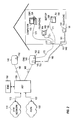
- FIG. 9 illustrates a schematic diagram of an RG system utilizing the RAP 900 and the RAM 920 for communications between the RG 200 and the remotely located TVs 199 .
- the RAM 920 is connected to the RG 200 with both speaker wire 990 and coaxial cable 210 .
- the RAM 920 is further connected to a splitter 177 that in turn connects to two RAPS 900 .
- the RAPS 900 are connected to the remotely located TVs 199 .
- Channel select commands are received by the antennae 910 as wireless signals and the RAP 900 transmits the wireless signals over coaxial cable 210 to the RAM 920 .
- the RAM 920 extracts the channel select commands and transmits them to the RG 200 over the speaker wire 990 .
- TV signals are transmitted from the RG 200 to the TVs 199 .
- the RAM 920 is connected to the RG 200 and thus receives the TV signals. However, the RAM 920 simply forwards the TV signals.
- the splitter 177 splits the TV signals so as to provide the TV signals to the two TVs 199 .
- the TV signals simply pass through the RAP 900 in this direction.
- FIG. 10 illustrates one embodiment of the RAP 900 .
- the RAP includes a combination of inductors and capacitors.
- FIG. 11 illustrates one embodiment of RAM 920 that includes a combination of inductors and capacitors.
- FIGS. 10 and 11 depict values associated with each of the components, however, this is only an example and should not be construed as limiting the scope of this invention. Rather, as one skilled in the art would know, different components, configurations of components, and/or values of components could be used to accomplish the same or a similar purpose and would thus be well within the scope of the current invention.
Abstract
A residential gateway (RG) for distributing video, data and telephony services to multiple devices within a residence is disclosed. The RG receives signals from a telecommunications network, converts the signals to formats compatible with the multiple devices, and transmits the appropriate signals to the appropriate devices. Wireless remote control devices associated with remotely located televisions (TVs) transmit channel select commands as wireless signals to the RG. The wireless signals are received by a Remote Antennae Package (RAP) that transmits the wireless signal over cable. A Remote Antennae Module (RAM) receives the wireless signal and extracts the channel select command.
Description
- This application is a continuation of, and claims the benefit under 35 U.S.C. § 120 of, co-pending U.S. patent application Ser. No. 09/525,488, filed Mar. 15, 2000, which was a continuation-in-part (CIP) of U.S. patent application Ser. No. 09/488,275, filed Jan. 20, 2000, which was a continuation of U.S. patent application Ser. No. 09/026,036 (now abandoned), filed Oct. 12, 1999, which was a continuing prosecution application of U.S. patent application Ser. No. 09/026,036, filed on Feb. 19, 1998, which claimed priority to U.S. provisional patent application No. 60/038,276, filed on Feb. 19, 1997. Each of U.S. patent applications Ser. Nos. 09/488,275, 09/026,036, and 60/038,276 is hereby incorporated by reference in its entirety.
- The present invention relates to an apparatus and method for the distribution of video, data, telephony and other telecommunications services from a single point to multiple devices within a residence.
- Advances in the field of telecommunications allow large amounts of digital information to be delivered to a residence. Digital telecommunications networks (access systems), such as Hybrid-Fiber-Coax (HFC), Fiber-to-the-Curb (FTTC), and Digital Subscriber Line (DSL), can provide both traditional telecommunications services such as Plain Old Telephone Service (POTS) as well as advanced services such as Switched Digital Video (SDV) and high-speed data access. Devices inside the residence, will be connected to the network by twisted wire pairs which provide telephone services today, or by coaxial cable similar to that used by cable operators to provide cable TV services. Because of this range of services, it is likely that digital networks will be widely deployed. In a widespread deployment of digital networks, millions of homes will connect to the digital network.
- Because the majority of new video services will be digital, and because existing televisions (TVs) are analog, there is a requirement for a device which converts the digital signals supplied by the network to analog signals compatible with existing TVs. Presently available TV set-tops can perform this function, but are expensive. Moreover, many homes have more than one TV, and would therefore require multiple TV set-tops to receive and convert the digital signals at each location within the home. Furthermore, there is a need for an interface subsystem for each device connected to the digital network. For example, a Premises Interface Device (PID) to extract time division multiplexed information and generate a telephone signal, and an Ethernet Bridge or Router (EBR) to generate a signal compatible with a computer.
- For the foregoing reasons, there is a need for a centralized unit in the residence which can provide: a central connectivity point to the digital network; digital to analog conversion; and supporting communications with multiple locations within the home (e.g., telephone, computer, TV). A centrally located in-home device is usually referred to as a residential gateway (RG).
- The present invention discloses a method and an apparatus for receiving signals from a telecommunications network, decoding the signals, and transmitting the decoded signals to a plurality of devices. In a preferred embodiment, the telecommunications network is a digital network and the signals include video signals, and may possibly include telephone signals, computer signals, and signals for other devices. In a preferred embodiment, the plurality of devices includes multiple televisions (TVs) and may possibly include telephones, computers and other devices. The apparatus is commonly known as residential gateway (RG).
- In one embodiment, a method of distributing video signals from a RG within a residential environment having a plurality of TVs locatable in at least two separate locations is disclosed. The method includes receiving at least one channel select command from one of a plurality of remote control devices associated with a respective one of the plurality of TVs. At least a first one of the plurality of remote control devices is a wireless remote control device that transmits the channel select command as a wireless signal. A video signal from a telecommunications network is received in response to the at least one channel select command. At least one series of video packets corresponding to the at least one channel select command is constructed from the video signal. The at least one series of video packets is transmitted over a video packet bus to a plurality of video decoders. The at least one series of video packets is decoded to produce at least one TV signal. The decoding is performed by at least one of the plurality of video decoders.
- In one embodiment, a method of distributing video signals from a RG within a residential environment having a plurality of TVs locatable in at least two separate locations is disclosed. The method includes receiving at least one channel select command from one of a plurality of remote control devices associated with a respective one of the plurality of TVs. At least a first one of the plurality of remote control devices is a optical remote control device that transmits the channel select command directly to the RG as a optical signal. A video signal from a telecommunications network is received in response to the at least one channel select command. At least one series of video packets corresponding to the at least one channel select command is constructed from the video signal. The at least one series of video packets is transmitted over a video packet bus to a plurality of video decoders. The at least one series of video packets is decoded to produce at least one TV signal. The decoding is performed by at least one of the plurality of video decoders.
- In one embodiment, a RG for distributing video signals to a plurality of TVs locatable within at least two separate locations in a residential environment is disclosed. The RG includes a plurality of remote control devices associated with a respective one of the plurality of TVs for transmitting channel select commands. At least a first one of the plurality of remote control devices is a wireless remote control device that transmits the channel select command as a wireless signal. A network interface module receives signals including video signals from a telecommunications network. The received video signals correspond to the channel select commands. A means for constructing at least one series of video packets from the received video signals is provided. A plurality of video processors decode the at least one series of video packets to produce at least one TV signal. A video packet bus transports the at least one series of video packets to the plurality of video processors.
- In one embodiment, a RG for distributing video signals to a plurality of TVs locatable within at least two separate locations in a residential environment is disclosed. The RG includes a plurality of remote control devices associated with a respective one of the plurality of TVs for transmitting channel select commands. At least a first one of the plurality of remote control devices is a optical remote control device that transmits the channel select command directly to the RG as a optical signal. A network interface module receives signals including video signals from a telecommunications network. The received video signals correspond to the channel select commands. A means for constructing at least one series of video packets from the received video signals is provided. A plurality of video processors decode the at least one series of video packets to produce at least one TV signal. A video packet bus transports the at least one series of video packets to the plurality of video processors.
- In one embodiment, a method for receiving and decoding signals from a telecommunications network at a RG, and transmitting decoded signals from the RG to a plurality of devices including multiple TVs is disclosed. The method includes connecting the RG to the telecommunications network and to each of the plurality of devices so that all communications between the devices and the telecommunications network must pass through the RG. A first one of the multiple TVs can be directly coupled to and located in close proximity to the RG. A TV channel is selected for at least one of the multiple TVs by programming an associated remote control device to transmit a channel select command. Each of the multiple TVs have an associated remote control device and the remote control device associated with the first TV transmits the channel select command to a receiver within the RG. The at least one channel select command is transmitted to the telecommunications network. A video signal is received from the telecommunications network corresponding to the at least one channel select command. The video signal is converted into at least one series of video packets. The at least one series of video packets is decoded into at least one TV signal. The decoding performed by at least one of a plurality of video decoders. The at least one TV signal is then transmitted to the appropriate TV.
- In one embodiment, a RG for receiving and decoding signals from a telecommunications network and transmitting decoded signals to a plurality of devices including multiple TVs is disclosed. The RG includes a network interface module for receiving the signals, including video signals, from the telecommunications network. A means for converting the video signal into at least one series of video packets is provided. A plurality of video decoders decodes the at least one series of video packets into at least one TV signal corresponding to at least one channel select command, and transmits the at least one TV signal to the corresponding TV. A receiver receives the channel select commands from a first remote control device associated with a first one of the multiple TVs that can be directly coupled to and in close proximity to the RG.
- In one embodiment, a method for receiving and decoding signals from a telecommunications network at a RG, and transmitting the decoded signals from the RG to a plurality of devices including multiple TVs is disclosed. The method includes connecting the RG to the telecommunications network and to each of the plurality of devices that will communicate with the telecommunications network through the RG. A TV channel to view for at least one of the multiple TVs is selected by programming an associated remote control device to transmit a channel select command. At least one of the remote control devices transmits the channel select command directly to a receiver within the RG. The at least one channel select command is transmitted to the telecommunications network. A video signal is received from the telecommunications network corresponding to the at least one channel select command. The video signal is decoded into at least one TV signal. The decoding is performed by at least one of a plurality of video decoders. The at least one TV signal is transmitted to the appropriate TV.
- In one embodiment, a RG for receiving and decoding signals from a telecommunications network and transmitting the decoded signals to a plurality of devices including multiple TVs is disclosed. The RG includes: a network interface module for receiving the signals, including video signals, from the telecommunications network; a plurality of video decoders for decoding the video signals into at least one TV signal corresponding to at least one channel select command, and transmitting the at least one TV signal to the corresponding TV; and a receiver for directly receiving channel select commands from at least one remote control device associated with one of the multiple TVs.
- In one embodiment, a method for receiving and decoding signals from a telecommunications network at a RG, and transmitting the decoded signals from the RG to a plurality of devices including multiple TVs is disclosed. The method includes: connecting the RG to the telecommunications network and to at least one TV that is remotely located from the RG; selecting a TV channel to view for the at least one TV by programming an associated wireless remote control device, wherein the wireless remote control device transmits a channel select command as a wireless signal to a remote antennae package connected to the TV, the remote antennae package receives the wireless signal and transmits the wireless signal over cable to a remote antennae module which demodulates the wireless signal and extracts the portion corresponding to the channel select command; transmitting the channel select command to the telecommunications network; receiving a video signal from the telecommunications network corresponding to the channel select command; decoding the video signal into a TV signal, the decoding performed by one of multiple video decoders associated with the multiple TVs; and transmitting the TV signal to the at least one TV.
- In one embodiment, a RG for receiving and decoding signals from a telecommunications network and transmitting the decoded signals to a plurality of devices including multiple TVs is disclosed. The RG includes: a network interface module for transmitting upstream signals, including channel select commands, to the telecommunications network and receiving downstream signals, including video signals, from the telecommunications network; a plurality of video decoders for decoding the video signals into at least one TV signal corresponding to at least one channel select command, and transmitting the at least one TV signal to the corresponding TV; and a remote control device for processing the channel select commands. At least one of the channel select commands is extracted from a wireless signal which was transmitted from a wireless remote control device to a remote antennae package connected to the associated TV. The remote antennae package transmits the wireless signal over cable to a remote antennae module which demodulates the wireless signal and extracts the portion corresponding to the channel select command.
- These and other features and objects of the invention will be more fully understood from the following detailed description of the preferred embodiments which should be read in light of the accompanying drawings.
- The accompanying drawings, which are incorporated in and form a part of the specification, illustrate the embodiments of the present invention and, together with the description serve to explain the principles of the invention.
- In the drawings:
- FIG. 1 illustrates a hybrid-fiber-coax (HFC) access system;
- FIG. 2 illustrates a fiber-to-the-curb (FTTC) access system;
- FIG. 3 illustrates an FTTC access system including a residential gateway (RG), according to one embodiment;
- FIG. 4 illustrates a Digital Subscriber Line (DSL) access system including an RG, according to one embodiment;
- FIG. 5 illustrates an RG architecture, according to one embodiment;
- FIG. 6 illustrates the use of the RG with the residence, according to one embodiment;
- FIG. 7 illustrates the use of the RG with the residence, according to one embodiment;
- FIG. 8 illustrates an RG architecture, according to one embodiment;
- FIG. 9 illustrates a schematic of the RG configuration of FIG. 7;
- FIG. 10 illustrates a schematic of the Remote Antennae Package (RAP), according to one embodiment; and
- FIG. 11 illustrates a schematic of the Remote Antennae Module (RAM), according to one embodiment.
- In describing a preferred embodiment of the invention illustrated in the drawings, specific terminology will be used for the sake of clarity. However, the invention is not intended to be limited to the specific terms so selected, and it is to be understood that each specific term includes all technical equivalents which operate in a similar manner to accomplish a similar purpose.
- With reference to the drawings, in general, and FIGS. 1 through 11 in particular, the method and apparatus of the present invention are disclosed.
- FIG. 1 illustrates a Hybrid-Fiber-Coax (HFC) digital network in which various devices within a
residence 190 are connected to a Video Network (VN) 408 or a data and voice network (DVN) 404. The devices in theresidence 190 can include a Premises Interface Device (PID) 196 connected to atelephone 194, a television (TV) set top-counter 198 connected to aTV 199, an Ethernet Bridge or Router (EBR) 191 connected to acomputer 193, or other devices. - The HFC network illustrated in FIG. 1 works by connecting a cable headend (HE) 400 to the
DVN 404 and theVN 408. The physical interface to theDVN 404 may be copper wire pairs carrying either DS-1 or DS-3 signals. The physical interface to theVN 408 may be via a wide area network (WAN). - The
Cable HE 400 is connected to a plurality of optical to electrical (O/E) nodes 410 (only one illustrated) withfiber optic cables 160. The O/E nodes 410 are located within the communities serviced by the HFC network. Each O/E node 410 provides service for up to 500 residences within the given community. Since such a large number of users are being serviced by one O/E node 410,amplifiers 420 are required. The O/E node 410 connects to theresidence 190 viacoaxial cable 170. Thecoaxial cable 170 is received by asplitter 177 within theresidence 190 so that internalcoaxial wiring 171 can route the data being transmitted to the various devices. Each device connected to the internalcoaxial wiring 171 will require an interface sub-system which can convert the current format of the signal being transmitted over the internalcoaxial wiring 171 to the service interface required by the devices (i.e., telephone, TV, computer, or other devices). In a preferred embodiment, thePID 196 extracts time division multiplexed information carried on the internal coaxial wiring and generates a telephone signal compatible with thetelephone 194. Similarly, the TV set-top 198 converts digital video signals to analog signals compatible with theTV 199. Likewise, theEBR 191 generates a signal compatible with thecomputer 193. - FIG. 2 illustrates a Fiber-to-the-Curb (FTTC) network in which various devices in the
residence 190 are connected to a Public Switched Telecommunications Network (PSTN) 100 or an Asynchronous Transfer Mode (ATM)network 110. The devices in theresidence 190 can include telephones 194 (with or without a PID 196),TV 199 with a TV set-top 198, andcomputer 193 with aEBR 191. - The FTTC network illustrated in FIG. 2 works by connecting a Host Digital Terminal (HDT) 130 to the
PSTN 100 and theATM network 110. A PSTN-HDT interface 103 is specified by standards bodies, and in the U.S. is specified by Bellcore specifications TR-TSY-000008, TR-NWT-000057 or GR-NWT-000303, which are incorporated herein by reference. TheHDT 130 can also receive special service signals from private or non-switched public networks. The physical interface to thePSTN 100 may be twisted wire pairs carrying DS-1 signals, or optical fibers carrying Optical Carrier (OC)-3 optical signals. - An ATM network-
HDT interface 113 can be realized using an OC-3 or OC-12c optical interface carrying ATM cells. In a preferred embodiment, theHDT 130 has three OC-12c broadcast ports, which receive signals carrying ATM cells, and one OC-12c interactive port which receives and transmits signals. - An element management system (EMS) 150 is connected to the
HDT 130 and forms part of an Element Management Layer (EML) which is used to provision services and equipment on the FTTC network, in the central office where theHDT 130 is located, in the field, or in theresidences 190. TheEMS 150 is software based and can be run on a personal computer in which case it will support oneHDT 130 and the associated digital network equipment connected to it, or can be run on a workstation to supportmultiple HDTs 130 and the associated digital network equipment. - Optical Network Units (ONUs) 140 are located in the serving area and are connected to the
HDT 130 viaoptical fiber 160. Digital signals, having a format which is similar to the Synchronous Digital Hierarchy (SDH) format, are transmitted to and from eachONU 140 over theoptical fiber 160 at a rate of at least 155 Mb/s, and preferably 622 Mb/s. In a preferred embodiment, theoptical fiber 160 is a single-mode fiber and a dual wavelength transmission scheme is used to communicate between theONU 140 and theHDT 130. In an alternate embodiment, a single wavelength scheme is used in which low reflectivity components are used to permit transmission and reception on one fiber. - A Telephony Interface Unit (TIU) 145 in the
ONU 140 generates an analog Plain Old Telephone signal (POTs) which is transported to theresidence 190 via a twisted wire pair,drop line cable 180. At the residence 190 a Network Interface Device (NID) 183 provides for high-voltage protection and serves as the interface and demarcation point between the twisted wire pair,drop line cable 180 and the twisted wire pairs 181 internal to theresidence 190. In a preferred embodiment, theTIU 145 generates POTs signals for sixresidences 190, each having a separate twisted wire pair,drop line cable 180 connected to theONU 140. - As shown in FIG. 2, a Broadband Interface Unit (BIU) 152 is located in the
ONU 140 and generates broadband signals which contain video, data and voice information. TheBIU 152 modulates data onto a RF carrier and transmits the data to theresidence 190 overmedia 170, such as a coaxial, drop line cable or a twisted wire pair, drop line cable. Themedia 170 connects to theresidence 190 at asplitter 177. The data then travels from thesplitter 177 to the devices within theresidence 190 overcoaxial wiring 171 internal to theresidence 190. - In a preferred embodiment, 64
ONUs 140 are served by eachHDT 130 and eachONU 140 serves 8residences 190. In an alternate embodiment, eachONU 140 serves 16residences 190. - As shown in FIG. 2, each device connected to the internal
coaxial wiring 171 will require an interface sub-system which can convert the current format of the signal being transmitted over the internalcoaxial wiring 171 to the service interface required by the devices (i.e.,telephone 194,TV 199, computer, or other devices). In a preferred embodiment, thePID 196 extracts time division multiplexed information carried on the internalcoaxial wiring 171 and generates a telephone signal compatible with thetelephone 194. Similarly, the TV set-top 198 converts digital video signals to analog signals compatible with theTV 199. Likewise, theEBR 191 generates a signal compatible with the computer. - In the system illustrated in FIG. 2, the
NID 183 is located external to theresidence 190, at what is known in the industry as the network demarcation point. For the delivery of telephony services theNID 183 is a passive device whose principal functions are lightning protection and the ability to troubleshoot the network by allowing connection of atelephone 194 to the twisted wire pair,drop line cable 180 to determine if wiring problems exist on the internal twisted wire pairs 181. - FIG. 3 illustrates a residential gateway (RG) 200 located within the
residence 190. In the embodiment illustrated, the digital network is an FTTC network and themedia 170 is a coaxial, drop line cable for connecting to and communicating with theRG 200. TheRG 200 generates signals compatible with the devices in theresidence 190, thus reducing the number of interface sub-systems required in theresidence 190 to interface between the FTTC network and the devices (i.e.,telephone 194,TV 199, and the computer 193). The devices are connected either directly or indirectly to theRG 200 instead of to an interface sub-system. For example, thecomputer 193 and thetelephone 194 may be directly connected to theRG 200 via internal twisted wire pairs 181. As one skilled in the art would know,multiple computers 193 ortelephones 194 could be connected to theRG 200 by using a splitter external to theRG 200, or by having additional Ethernet ports for thecomputers 193 or telephone jacks for thetelephones 194 in the housing of theRG 200. - The
TV 199 may be connected directly to theRG 200 viavideo cables 205. In a preferred embodiment, thevideo cables 205 used 25 for the direct RG-TV connection 205 are a four-conductor cable carrying S-video signals. As one skilled in the art would know,additional TVs 199 could be directly connected to theRG 200 by using a splitter or additional S-video connectors in the housing of theRG 200. The preferred embodiment would be to have additional S-video connectors so that the quality of the video signals would be maintained. Moreover, theTVs 199 directly connected to theRG 200 would have to be within close proximity to theRG 200 as S-video signals can only maintain their quality for a limited distance. -
Additional devices 192, such asadditional TVs 199, which are remotely located from the RG 200 (hereinafter referred to as remotely located TVs 199) may be connected to theRG 200. One embodiment connects theadditional devices 192 to theRG 200 viamedia 210, such as internal coaxial cable wiring, and thesplitter 177. That is, one port, such as a coaxial connector, on theRG 200 can connect multipleadditional devices 192 to theRG 200. This type of connection is known as a point-to-multipoint connection. Alternatively, eachadditional device 192 could be directly connected to theRG 200 using thesingle media 210, thesplitter 177 is not used. This type of connection is known as a point-to-point connection and would require theRG 200 to have multiple ports, such as coaxial connectors. - It would be obvious to one skilled in the art that any of the devices (
TVs 199,telephones 194,computers 193, etc.) could be connected to theRG 200 with any type of cable that can transmit signals compatible with the particular device. Moreover, theRG 200 can include any type of ports that can receive signals compatible with a particular device. - FIG. 4 illustrates an embodiment, in which the digital network is a Digital Subscriber Line (DSL) network. In this embodiment, the DSL network replaces the
ONU 140 with a Universal Service Access Multiplexer (USAM) 340. TheUSAM 340 is located in the serving area, and is connected to theHDT 130 viaoptical fiber 160. A twisted wire pair,drop line cable 180 to provide communications to and from theRG 200. - The
USAM 340 includes axDSL modem 350 which provides for the transmission of high-speed digital data to and from theresidence 190, over the twisted wire pair,drop line cable 180. When used herein, the term xDSL refers to any one of the twisted wire pair digital subscriber loop transmission techniques including High Speed Digital Subscriber Loop, Asymmetric Digital Subscriber Loop, Very high speed Digital Subscriber Loop, Rate Adaptive Digital Subscriber Loop, or other similar twisted wire pair transmission techniques. Such transmission techniques are known to those skilled in the art. ThexDSL modem 350 contains the circuitry and software to generate a signal which can be transmitted over the twisted wire pair,drop line cable 180, and which can receive high speed digital signals transmitted from theRG 200 or other devices connected to the subscriber network. - Traditional analog telephone signals are combined with the digital signals for transmission to the
residence 190. A NID/filter 360 replaces theNID 183 of FIGS. 2 and 3, and is used to separate the analog telephone signals from the digital signals. The majority of xDSL transmission techniques leave the analog voice portion of the spectrum (from approximately 400 Hz to 4,000 Hz) undisturbed. The analog telephone signal, once separated from any digital data signals in the spectrum, is sent to thetelephone 194 over the internal twisted wire pairs 181. The digital signals that are separated at the NID/filter 360 are 20 sent from a separate port on the NID/filter 360 to theRG 200. TheRG 200 serves as the interface to the other devices (TVs 199,computers 193, and additional telephones 194) in theresidence 190. The connection of the devices within theresidence 190 to theRG 200 is the same as described above with respect to FIG. 3. - The embodiment illustrated in FIG. 4 is a central office configuration, which includes a USAM Central Office Terminal (COT) 324 connected to the
HDT 130. A USAM COT-HDT connection 325, is a twisted wire pair which transmits a STS3c signal in a preferred embodiment. A PSTN-USAM COT interface 303 is one of 30 the Bellcore specified interfaces including TR-TSY-000008, TR-NWT-000057 or TR-NWT-000303, which are all incorporated herein by reference. TheUSAM COT 324 has the same mechanical configuration as theUSAM 340 in terms of power supplies and common control cards, but has line cards which support twisted wire pair interfaces to the PSTN 100 (including DS-1 interfaces) and cards which support STS3c transmission over the twisted wire pair of the USAM COT-HDT connection 325. - The embodiment illustrated in FIG. 4, also includes a Channel Bank (CB) 322 in the central office. The
CB 322 is used to connectspecial networks 310, comprised of signals from special private or public networks, to the DSL network via a special networks-CB interface 313. In a preferred embodiment, a 10 CB-USAM COT connection 320 includes DS1 signals over twisted wire pairs. - The
RG 200 can be located anywhere within the residence 190 (i.e., in any of the living spaces, in the basement, in the garage, in a wiring closet, in the attic), or external to the residence (i.e., on an external wall). For external locations, theRG 200 will require a hardened enclosure and components which work over a larger temperature range than those used for theRG 200 located internal to theresidence 190. Techniques for developing hardened enclosures and selecting temperature tolerant components are known to those skilled in the art. - FIG. 5 illustrates one embodiment of the
RG 200. TheRG 200 includes anetwork connection 460 for connecting to the digital network. Thenetwork connection 460 will vary depending on the digital network that the RG is connecting to. That is, thenetwork connection 460 will depend on whether the digital network for the area theresidence 190 is located within is an FTTC network, a DSL network, or other type of digital network. For example, if the drop line from the digital network to theRG 200 is a coaxial cable (i.e., the FTTC network of FIG. 3) thenetwork connection 460 should be a coaxial cable connector. If the drop line from the digital network to theRG 200 is twisted wire pair cable (i.e., the DSL network of FIG. 4) thenetwork connection 460 should be a connector capable of receiving twisted wire pairs, such as a telephone jack. As one skilled in the art would know, thenetwork connection 460 could be various different types of connectors as long as the connector is capable of receiving the signals being transmitted over the drop line from the digital network. - The
network connection 460 is connected to a Network Interface Module (NIM) 410. TheNIM 410 receives all data from and transmits all data to the digital network and thus contains the appropriate modem technology. As with thenetwork connection 460, the type ofNIM 410 utilized depends on the type of digital network that theRG 200 is connected to. In a preferred embodiment, different types ofNIMs 410 are utilized for digital networks having coaxial drop line cables (i.e., the FTTC network of FIG. 3) than for digital networks having twisted wire pair drop line cables (i.e., the DSL network of FIG. 4). - Regardless of the type of
NIM 410 utilized, theNIM 410 interfaces to amother board 414 which provides the basic functionality of theRG 200. Themother board 414 may contain amicroprocessor 434,memory 436, apower supply 440, amain MPEG processor 430, anEthernet processor 438, and a Remote Control (RC)processor 442. As one skilled in the art would recognize, themother board 414 could contain additional components, or some of the components illustrated as being part of themother board 414 could removed from or located elsewhere within theRG 200, without departing from the scope of the current invention. - The
RG 200 receives power from a power source, which in a preferred embodiment is an AC outlet, via aplug 476, which in a preferred embodiment is an AC plug. Thepower supply 440 converts the voltage from the AC outlet, for example 120 volts AC in atypical residence 190, to the voltages necessary for each of the components of theRG 200 to operate. Thepower supply 440 is illustrated as being an element of themother board 414, but as one skilled in the art would know, thepower supply 440 could be a separate component within theRG 200. - The
microprocessor 434 controls the operation of theRG 200. For example, themicroprocessor 434 may control the transfer of data between each of the elements of theRG 200. Thememory 436 may store operating programs required by themicroprocessor 434, data received from the digital network or any of the devices in theresidence 190 connected to theRG 200, or other data or programs required by theRG 200. - The
Ethernet processor 438 converts ATM cells received by theNIM 410 into the appropriate form for transmission to the devices, such as thecomputers 193. Thecomputers 193 are connected to theRG 200 via anEthernet connector 478 located in the housing of theRG 200. As illustrated in FIG. 5, theRG 200 has only oneEthernet connector 478. This would seem to infer that only one computer could be connected to theRG 200. However, as one skilled in the art would know, a splitter could be used to connectadditional computers 193 to theRG 200. Furthermore, an alternative embodiment could includeadditional Ethernet connectors 478 located in the housing of theRG 200 so thatadditional computers 193 could be connected to theRG 200. - Within the
main MPEG processor 430 there is a Video Segmentation and Re-assembly (VSAR)module 432 which constructs Motion Picture Experts Group (MPEG) packets from an ATM stream received from theNIM 410. In addition to constructing the MPEG packets, theVSAR module 432 can reduce jitter in the MPEG packets which arises from transmission of those packets over theATM network 110, as well as constructing a useable MPEG stream in spite of lost ATM cells which contain partial MPEG packets. It would be obvious to one skilled in the art that theVSAR module 432 does not have to be part of themain MPEG processor 430. For example, theVSAR module 432 could be its own module on themother board 414, could be its own subassembly, or could be part of another processor, such as theNIM 410. - While the
VSAR module 432 has been described as constructing MPEG packets from received ATM streams, this is in no way intended to limit the scope of the invention. Rather, this is simply the current preferred embodiment. That is, digital data is currently transmitted over the digital network in ATM streams and digital video data is currently compressed according to an MPEG standard (currently the MPEG-2 standard). It is within the scope of the current invention to receive digital data from a digital network in any format and for the video data to be compressed in any format. That is, one skilled in the art could modify theVSAR module 432 to handle new transmission or compression formats without departing from the scope of the current invention. - The
main MPEG processor 430 can also decompress the MPEG packets, which are constructed by theVSAR module 432, to generate video signal(s) compatible withpresent TVs 199. In one embodiment, themain MPEG processor 430 generates video signal(s) having an S-video format. The S-video signal(s) can be transmitted over an S-video connector 474 to aTV 199 having an S-video port via an S-video cable 205. As one skilled in the art knows, S-video signals are a higher quality video signal because the chrominance and luminance information are separated. TheTV 199 receiving the S-video signals should be located in close proximity to theRG 200 to ensure the quality of the S-video signal. As illustrated, there is only oneTV 199 connected to theRG 200 with the S-video cable 205 and only one S-video connector 474. However, this is not intended to limit the scope of the invention as it would be possible to have multiple TVs 199 (assuming they are located in close proximity to the RG 200) receive S-video signals from theRG 200 by splitting the signal transmitted from the single S-video connector 474 or by providing multiple S-video connectors in the housing of theRG 200. - In one embodiment, the
main MPEG processor 430 may decompress multiple MPEG packets corresponding to multiple TV channel selections to generate video signal(s) compatible with the current TV format, which in the U.S. is currently the National TV System Committee (NTSC) format. The invention however is not limited to the NTSC format. It is well within the scope of the current invention for the TV signals to be generated in accordance with the current standard for the time, whether it be the NTSC format or a new format. For example, themain MPEG processor 430 may decompress three video streams simultaneously to generate three video signals associated with three TV channel selections. The TV signals may be transmitted to theTVs 199 by either combining and modulating each TV signal over one media or by modulating each TV signal over a separate media. - The
RC processor 442 is capable of processing RC signals received by theRG 200. For example, in the embodiment illustrated in FIG. 5, theRC processor 442 receives optical signals, such as infrared (IR) signals, from anoptical receiver 472, such as an IR receiver, and wireless signals, such as UHF signals, from awireless receiver 470, such as a UHF receiver. One skilled in the art would recognize that theRC processor 442 could be designed to handle any type of channel select signals that were received from a variety of different RC devices. Moreover, one skilled in the art would recognize that theRC processor 442 is not limited to the illustrated configuration of being a module located on themother board 414. For example, theRC processor 442 could be located on another board or could be incorporated as part of another module. - The embodiment of the
RG 200 illustrated in FIG. 5, further includes theoptical receiver 472. Theoptical receiver 472 receives channel select commands for theTV 199 that is directly connected to theRG 200, preferably via the S-video port 474. As stated earlier, thisTV 199 will be in close proximity to the RG. In a preferred embodiment, theRG 200 would be located in a stereo cabinet with theTV 199 or on top of theTV 199, much like a VCR. As with a VCR, theTV 199 would be set to a particular channel, forexample channel 3 or 4 just like a VCR, and the control of the channel selection for theTV 199 would then be controlled by the optical RC sending channel select commands to theRG 200 directly. While the illustrated embodiment is the preferred embodiment, the current invention is not limited to using an optical RC to control theTV 199 directly connected to theRG 200. For example, the RC could be a wireless RC or a hard wired RC device. - The
RG 200 illustrated in FIG. 5, further includes thewireless receiver 470 for receiving channel select signals from the remotely locatedTVs 199 that are connected to theRG 200 and are located in separate rooms or even separate floors of theresidence 190. As with theTV 199 directly connected to the and located in close proximity to theRG 200, the remotely locatedTVs 199 would be set to a particular channel, forexample channel 3 or 4 just like a VCR, and the control of the channel selection for the remotely locatedTVs 199 would then be controlled by a wireless RC associated with eachTV 199. The wireless RC transmits the channel select commands to theRG 200 directly. - The
RG 200 also includes a set ofbuses 429 used to route information within theRG 200. As illustrated in FIG. 5, the set ofbuses 429 includes a Time Division Multiplexing (TDM)bus 420, a control bus 422, a MPEG bus 424, and an ATM bus 428. - The
RG 200 may also include a number of optional modules which can be inserted into theRG 200. The optional modules includeMPEG modules 450, a Digital Audio Visual Council (DAVIC)module 452, and atelephony module 454. All of the optional modules are connected to the control bus 422 in addition to being connected to at least one other bus which provides those modules with the appropriate types of data for the services supported by the module. - The
MPEG modules 450 provide for decompression of MPEG packets which are constructed by theVSAR processor 432. The MPEG modules are associated with remotely locatedTVs 199. As with the output of themain MPEG processor 430, the output of theMPEG modules 450 is a signal having a format compatible withpresent TVs 199. TheMPEG modules 450 can modulate the decompressed analog format video signal onto an available channel for transmission to the remotely locatedTVs 199 in theresidence 190. In a preferred embodiment, theMPEG modules 450 are insertable cards. Thus, the cards could be added after an initial installation to handleadditional TVs 199. For example, in one embodiment themain MPEG processor 430 may be capable of generating three TV signals so that theRG 200 can accommodate threeTVs 199 without the need for anyMPEG modules 450. If afourth TV 199 was added, or one of theTVs 199 had picture-in-picture, aMPEG module 450 would be required to generate a fourth TV signal. - The
DAVIC module 452 is for communicating with devices that have a signal format that is compatible with a signal format received from the digital network. That is, the DAVIC module transmits ATM signals to and receives ATM signal from these devices. Thus, theDAVIC module 452 allows theRG 200 to act as a pass through for these devices. These devices may include the interface sub-systems illustrated in FIGS. 1 and 2. This is beneficial because theRG 200 can be used in conjunction with previously purchased interface sub-systems if required or desired. - As illustrated in FIG. 5, the
MPEG modules 450 and theDAVIC module 452 are connected to acombiner 418 which combines the RF signals from those modules. It should be noted that this embodiment has only oneRF connector 466 so that thecombiner 418 is necessary to combine all the TV signals and ATM signals so they can be transmitted over asingle media 210 connected to theRF connector 466. Ifmultiple RF connectors 466 were provided, it is possible that thecombiner 418 would not be required or could be externally located. However, thecombiner 418 can also add other RF signals, such as off-air broadcast TV signals or Community Antenna TV (CATV) signals supplied by a cable TV company. Signals from the antenna or cable system are coupled to the RF pass-through 464, which in a preferred embodiment is an F-connector. Alow pass filter 482 is used in thecombiner 418 to insure that the frequencies used byMPEG modules 450 are available. The output of thecombiner 418 is connected to theRF connector 466, which in a preferred embodiment is an F-connector. - An
optional CATV module 480 can be inserted into theRG 200 to allow for mapping of off-air or cable video channels from their original frequencies to new frequencies for in-home distribution. TheRC processor 442 can control the channel selection and mapping via the control bus 422 which is connected to theCATV module 480. Either a hand-held optical RC or a wireless RC can be used to change the channel mapping of theCATV module 480. - The
RG 200 includes afront panel interface 462, which provides for connectivity between the front panel controls (buttons) and themicroprocessor 434. Through the front panel controls, the user can make channel changes as well as changing the configuration of the channels transmitted on the in-home coaxial network. - The
RG 200 also includes atelephony module 454, which transmits and receives information from theTDM bus 420 and produces an analog telephone signal which is compatible withtelephones 194. The interface for thetelephones 194 is atelephone jack 468, which in a preferred embodiment is an RJ-11 jack. - FIG. 6 illustrates one embodiment of how the
RG 200 could be configured within theresidence 190. As illustrated, the remotely locatedTVs 199 use awireless RC 500 to transmit channel select commands to theRG 200. In particular,TVs RG 200 and TV3, which is directly connected to theRG 200 via the S-video connector 474, are located on a first floor of theresidence 190.Wireless RCs TVs RG 200 as wireless signals. The wireless channel select commands are received by theRG 200 via thewireless receiver 470. The channel select commands forTV 3 are transmitted using anoptical RC 510. The optical channel select command is received by theoptical receiver 472 within theRG 200. - This embodiment illustrates
TVs RG 200 via a splitter. This is in no way intended to limit the scope of the invention. Rather, as previously discussed it is within the scope of this invention to have multiple coaxial connectors within the housing of theRG 200 so that each remotely locatedTV 199 can be directly connected to theRG 200. As one skilled in the art would know, there is a limit to how many ports can be added to the housing so there is a limit to how many separate remotely locatedTVs 199 can be connected directly to theRG 200. Thus, it possible to have some of the remotely locatedTVs 199 connected directly to a port in theRG 200 and others that are connected to a port via thesplitter 177. - One drawback to the embodiment that utilizes wireless RCs 500 and the
wireless receiver 470 within the RG 200 (as illustrated in FIG. 7), is that the further the wireless signals have to be transmitted and the more obstacles, such as walls, that the signals have to navigate around, the weaker the signal at thewireless receiver 470, and the more likely that the channel select command is lost or distorted. Moreover, the average consumer will more than likely point thewireless RC 500 at theTV 199, which is more than likely away from theRG 200 and thewireless receiver 470. - An alternative embodiment, for transmitting channel select commands from the remotely located
TVs 199 to theRG 200 is illustrated in FIG. 7. In this embodiment, a Remote Antennae Package (RAP) 900 is connected to each remotely locatedTV 199. 10 TheRAP 900 is a passive device for receiving and transmitting the wireless signals. TheRAP 900 includes anantenna 910, such as a ¼ wave dipole antenna, located in close proximity to theTV 199, and preferably mounted to theTV 199. Awireless RC 500 is used to select a channel. Thewireless RC 500 transmits a channel select command at one of the common wireless frequencies known to those skilled in the art. In a preferred embodiment, the wireless signal is transmitted at a frequency of approximately 433 MHz. The FCC regulations for wireless RCs imposes a maximum transmit power of 80.5 dbu V/m at a distance of 3 meters. Onesuch wireless RC 500 that can be used along with the current invention is the RCK-431N manufactured by DAE-Ryung. Theantenna 910 receives the channel select command and theRAP 900 transmits the wireless signal over the media 210 (i.e., coaxial cable) or themedia 210 and thesplitter 177. - A Remote Antenna Module (RAM) 920 which is located near, and preferably connected to the
RG 200, receives the wireless signal. TheRAM 920 demodulates the wireless signal and extracts the channel select command therefrom. In a preferred embodiment, the channel select command is extracted as an approximately 1 KHz audio signal. TheRAM 920 then transmits the channel select command to theRG 200 for processing. TheRAM 920 may be connected to theRG 200 with, for example audio wire better known as “speaker wire”. In an alternative embodiment, theRAM 920 may be directly mounted on theRG 200. In another alternative embodiment, theRAM 920 may be an integral part of theRG 200. - FIG. 8 illustrates an embodiment of the
RG 200 that includes aport 750 for receiving channel select commands from theRAM 920. The channel select commands are provided directly to theRC processor 442. In this embodiment, a wireless antennae is not required to receive the wireless signals. Moreover, this embodiment includesmultiple ports 630, such as TV connectors. Thus, thecombiner 418 of FIG. 5 is not required. Rather, this embodiment illustratesTV modules 654 for modulating the appropriate video channel over theappropriate port 630. - FIG. 9 illustrates a schematic diagram of an RG system utilizing the
RAP 900 and theRAM 920 for communications between theRG 200 and the remotely locatedTVs 199. As illustrated, theRAM 920 is connected to theRG 200 with bothspeaker wire 990 andcoaxial cable 210. TheRAM 920 is further connected to asplitter 177 that in turn connects to twoRAPS 900. TheRAPS 900 are connected to the remotely locatedTVs 199. Channel select commands are received by theantennae 910 as wireless signals and theRAP 900 transmits the wireless signals overcoaxial cable 210 to theRAM 920. TheRAM 920 extracts the channel select commands and transmits them to theRG 200 over thespeaker wire 990. TV signals are transmitted from theRG 200 to theTVs 199. As illustrated, theRAM 920 is connected to theRG 200 and thus receives the TV signals. However, theRAM 920 simply forwards the TV signals. Thesplitter 177 splits the TV signals so as to provide the TV signals to the twoTVs 199. The TV signals simply pass through theRAP 900 in this direction. - FIG. 10 illustrates one embodiment of the
RAP 900. In addition to theantenna 910, the RAP includes a combination of inductors and capacitors. FIG. 11 illustrates one embodiment ofRAM 920 that includes a combination of inductors and capacitors. FIGS. 10 and 11 depict values associated with each of the components, however, this is only an example and should not be construed as limiting the scope of this invention. Rather, as one skilled in the art would know, different components, configurations of components, and/or values of components could be used to accomplish the same or a similar purpose and would thus be well within the scope of the current invention. - Although this invention has been illustrated by reference to specific embodiments, it will be apparent to those skilled in the art that various changes and modifications may be made which clearly fall within the scope of the invention. The invention is intended to be protected broadly within the spirit and scope of the appended claims.
Claims (3)
1. In a residential environment having a plurality of televisions locatable in at least two separate locations, a method of distributing video signals from a residential gateway, the method comprising:
receiving at least one channel select command from one of a plurality of remote control devices associated with a respective one of the plurality of televisions, wherein at least a first one of the plurality of remote control devices is a wireless remote control device that transmits the channel select command as a wireless signal;
receiving the wireless signal from the first one of the plurality of remote control devices at a remote antennae package connected to the first one of the plurality of televisions;
transmitting the wireless signal from the remote antennae package over media;
receiving the wireless signal from the media at a remote antennae module located in close proximity to the residential gateway;
demodulating the wireless signal and extracting the portion corresponding to the channel select command;
transmitting the channel select command to the residential gateway;
receiving a video signal from a telecommunications network in response to the at least one channel select command;
constructing, from the video signal, at least one series of video packets corresponding to the at least one channel select command;
transporting the at least one series of video packets over a video packet bus to a plurality of video decoders; and
decoding the at least one series of video packets to produce at least one television signal, the decoding performed by at least one of the plurality of video decoders.
2. The method of claim 1 , wherein said demodulating the wireless signal includes demodulating the wireless signal and extracting therefrom the channel select command as an approximately 1 KHz signal.
3. A residential gateway for distributing video signals to a plurality of televisions locatable within at least two separate locations in a residential environment, said residential gateway comprising:
a plurality of remote control devices associated with a respective one of the plurality of televisions for transmitting channel select commands, wherein at least a first one of the plurality of remote control devices is a wireless remote control device that transmits the channel select command as a wireless signal;
a remote antennae package connected to the first one of the plurality of televisions associated with the first one of the plurality of remote control devices, the remote antennae package receiving the wireless signal and transmitting the wireless signal over media;
a remote antennae module for receiving the wireless signal from the remote antennae package, demodulating the wireless signal, extracting the portion corresponding to the channel select command, and transmitting the channel select command to the residential gateway;
a network interface module for receiving signals including video signals from a telecommunications network, wherein the received video signals correspond to the channel select commands;
means for constructing at least one series of video packets from the received video signals;
a plurality of video processors for decoding the at least one series of video packets to produce at least one television signal; and
a video packet bus for transporting the at least one series of video packets to said plurality of video processors.
Priority Applications (1)
| Application Number | Priority Date | Filing Date | Title |
|---|---|---|---|
| US10/443,744 US20030192053A1 (en) | 1997-02-19 | 2003-05-23 | Method and apparatus for transmitting wireless signals over media |
Applications Claiming Priority (5)
| Application Number | Priority Date | Filing Date | Title |
|---|---|---|---|
| US3827697P | 1997-02-19 | 1997-02-19 | |
| US09/026,036 US6317884B1 (en) | 1997-02-19 | 1998-02-19 | Video, data and telephony gateway |
| US48827500A | 2000-01-20 | 2000-01-20 | |
| US52548800A | 2000-03-15 | 2000-03-15 | |
| US10/443,744 US20030192053A1 (en) | 1997-02-19 | 2003-05-23 | Method and apparatus for transmitting wireless signals over media |
Related Parent Applications (1)
| Application Number | Title | Priority Date | Filing Date |
|---|---|---|---|
| US52548800A Continuation | 1997-02-19 | 2000-03-15 |
Publications (1)
| Publication Number | Publication Date |
|---|---|
| US20030192053A1 true US20030192053A1 (en) | 2003-10-09 |
Family
ID=28679020
Family Applications (1)
| Application Number | Title | Priority Date | Filing Date |
|---|---|---|---|
| US10/443,744 Abandoned US20030192053A1 (en) | 1997-02-19 | 2003-05-23 | Method and apparatus for transmitting wireless signals over media |
Country Status (1)
| Country | Link |
|---|---|
| US (1) | US20030192053A1 (en) |
Cited By (202)
| Publication number | Priority date | Publication date | Assignee | Title |
|---|---|---|---|---|
| US20020006137A1 (en) * | 2000-05-08 | 2002-01-17 | Rabenko Theodore F. | System and method for supporting multiple voice channels |
| US20030099245A1 (en) * | 2001-11-29 | 2003-05-29 | Yong-Hoe Kim | Host digital terminal |
| US20030177499A1 (en) * | 2002-03-14 | 2003-09-18 | Rodolico Joseph T. | Radio frequency distribution network system |
| US20030185177A1 (en) * | 2002-03-26 | 2003-10-02 | Interdigital Technology Corporation | TDD-RLAN wireless telecommunication system with RAN IP gateway and methods |
| US20030185178A1 (en) * | 2002-03-26 | 2003-10-02 | Interdigital Technology Corporation | TDD-RLAN wireless telecommunication system with RAN IP gateway and methods |
| US20040132403A1 (en) * | 2003-01-02 | 2004-07-08 | Agere Systems, Inc. | Wireless cable networking gateway and Wi-Fi system incorporating the same |
| WO2005062535A1 (en) * | 2003-12-22 | 2005-07-07 | Siemens Aktiengesellschaft | Method, telecommunications system and telecommunications handset for wireless communication and telecommunication in a 'smart home' environment |
| US20050249205A1 (en) * | 1997-12-15 | 2005-11-10 | Tellabs Research Limited | Telecommunication systems |
| US20060095940A1 (en) * | 2004-11-03 | 2006-05-04 | Yearwood Bradley N | Method and apparatus for distributing digital stream data to a user terminal |
| US20060197834A1 (en) * | 2005-03-07 | 2006-09-07 | Dorin Balanica | Matrix home studio |
| US20070174876A1 (en) * | 2006-01-24 | 2007-07-26 | Media Ip Holdings Llc | Method and system for providing broadband access, HDTV, and broadband-enabled services |
| US7313811B1 (en) * | 1997-02-19 | 2007-12-25 | General Instrument Corporation | Optical conversion device |
| US20080037520A1 (en) * | 2006-07-31 | 2008-02-14 | Robert C. Stein | Residential Gateway Translating Call Signaling Text Received With a Packet-Switched Telephony Call |
| US20080120655A1 (en) * | 2006-11-22 | 2008-05-22 | The Directv Group, Inc. | Integrated satellite master antenna television unit |
| US20090113492A1 (en) * | 2007-10-31 | 2009-04-30 | Norin John L | Smatv headend using ip transport stream input and method for operating the same |
| US20090300219A1 (en) * | 2008-05-30 | 2009-12-03 | At & T Delaware Intellectual Property, Inc. | Transfer of contact data to a navigation device |
| US7698723B2 (en) * | 2000-12-28 | 2010-04-13 | At&T Intellectual Property I, L.P. | System and method for multimedia on demand services |
| US20110202952A1 (en) * | 2005-09-02 | 2011-08-18 | The Directv Group, Inc. | Network fraud prevention via registration and verification |
| US20130023203A1 (en) * | 2010-03-29 | 2013-01-24 | James Kakaire | Transputer |
| US8601519B1 (en) | 2000-12-28 | 2013-12-03 | At&T Intellectual Property I, L.P. | Digital residential entertainment system |
| US8677423B2 (en) | 2000-12-28 | 2014-03-18 | At&T Intellectual Property I, L. P. | Digital residential entertainment system |
| US8789115B2 (en) | 2005-09-02 | 2014-07-22 | The Directv Group, Inc. | Frequency translation module discovery and configuration |
| US8839312B1 (en) | 2005-04-01 | 2014-09-16 | The Directv Group, Inc. | Power balancing signal combiner |
| US20150029397A1 (en) * | 2013-07-25 | 2015-01-29 | DvineWave Inc. | Tv with integrated wireless power transmitter |
| US8978084B2 (en) | 2006-06-09 | 2015-03-10 | The Directv Group, Inc. | Presentation modes for various format bit streams |
| US20160100124A1 (en) * | 2013-05-10 | 2016-04-07 | Energous Corporation | Tv system with wireless power transmitter |
| US20160164301A1 (en) * | 2014-12-08 | 2016-06-09 | Disney Enterprises, Inc. | Resonant cavity mode enabled wireless power transfer |
| US9787103B1 (en) | 2013-08-06 | 2017-10-10 | Energous Corporation | Systems and methods for wirelessly delivering power to electronic devices that are unable to communicate with a transmitter |
| US9793758B2 (en) | 2014-05-23 | 2017-10-17 | Energous Corporation | Enhanced transmitter using frequency control for wireless power transmission |
| US9800080B2 (en) | 2013-05-10 | 2017-10-24 | Energous Corporation | Portable wireless charging pad |
| US9800172B1 (en) | 2014-05-07 | 2017-10-24 | Energous Corporation | Integrated rectifier and boost converter for boosting voltage received from wireless power transmission waves |
| US9806564B2 (en) | 2014-05-07 | 2017-10-31 | Energous Corporation | Integrated rectifier and boost converter for wireless power transmission |
| US9812890B1 (en) | 2013-07-11 | 2017-11-07 | Energous Corporation | Portable wireless charging pad |
| US9819230B2 (en) | 2014-05-07 | 2017-11-14 | Energous Corporation | Enhanced receiver for wireless power transmission |
| US9824815B2 (en) | 2013-05-10 | 2017-11-21 | Energous Corporation | Wireless charging and powering of healthcare gadgets and sensors |
| US9825674B1 (en) | 2014-05-23 | 2017-11-21 | Energous Corporation | Enhanced transmitter that selects configurations of antenna elements for performing wireless power transmission and receiving functions |
| US9838083B2 (en) | 2014-07-21 | 2017-12-05 | Energous Corporation | Systems and methods for communication with remote management systems |
| US9843213B2 (en) | 2013-08-06 | 2017-12-12 | Energous Corporation | Social power sharing for mobile devices based on pocket-forming |
| US9843229B2 (en) | 2013-05-10 | 2017-12-12 | Energous Corporation | Wireless sound charging and powering of healthcare gadgets and sensors |
| US9843201B1 (en) | 2012-07-06 | 2017-12-12 | Energous Corporation | Wireless power transmitter that selects antenna sets for transmitting wireless power to a receiver based on location of the receiver, and methods of use thereof |
| US9847679B2 (en) | 2014-05-07 | 2017-12-19 | Energous Corporation | System and method for controlling communication between wireless power transmitter managers |
| US9847669B2 (en) | 2013-05-10 | 2017-12-19 | Energous Corporation | Laptop computer as a transmitter for wireless charging |
| US9847677B1 (en) | 2013-10-10 | 2017-12-19 | Energous Corporation | Wireless charging and powering of healthcare gadgets and sensors |
| US9853458B1 (en) | 2014-05-07 | 2017-12-26 | Energous Corporation | Systems and methods for device and power receiver pairing |
| US9853692B1 (en) | 2014-05-23 | 2017-12-26 | Energous Corporation | Systems and methods for wireless power transmission |
| US9853485B2 (en) | 2015-10-28 | 2017-12-26 | Energous Corporation | Antenna for wireless charging systems |
| US9859756B2 (en) | 2012-07-06 | 2018-01-02 | Energous Corporation | Transmittersand methods for adjusting wireless power transmission based on information from receivers |
| US9859757B1 (en) | 2013-07-25 | 2018-01-02 | Energous Corporation | Antenna tile arrangements in electronic device enclosures |
| US9859797B1 (en) | 2014-05-07 | 2018-01-02 | Energous Corporation | Synchronous rectifier design for wireless power receiver |
| US9859758B1 (en) | 2014-05-14 | 2018-01-02 | Energous Corporation | Transducer sound arrangement for pocket-forming |
| US9866279B2 (en) | 2013-05-10 | 2018-01-09 | Energous Corporation | Systems and methods for selecting which power transmitter should deliver wireless power to a receiving device in a wireless power delivery network |
| US9867062B1 (en) | 2014-07-21 | 2018-01-09 | Energous Corporation | System and methods for using a remote server to authorize a receiving device that has requested wireless power and to determine whether another receiving device should request wireless power in a wireless power transmission system |
| US9871301B2 (en) | 2014-07-21 | 2018-01-16 | Energous Corporation | Integrated miniature PIFA with artificial magnetic conductor metamaterials |
| US9871387B1 (en) | 2015-09-16 | 2018-01-16 | Energous Corporation | Systems and methods of object detection using one or more video cameras in wireless power charging systems |
| US9871398B1 (en) | 2013-07-01 | 2018-01-16 | Energous Corporation | Hybrid charging method for wireless power transmission based on pocket-forming |
| US9876394B1 (en) | 2014-05-07 | 2018-01-23 | Energous Corporation | Boost-charger-boost system for enhanced power delivery |
| US9876379B1 (en) | 2013-07-11 | 2018-01-23 | Energous Corporation | Wireless charging and powering of electronic devices in a vehicle |
| US9876648B2 (en) | 2014-08-21 | 2018-01-23 | Energous Corporation | System and method to control a wireless power transmission system by configuration of wireless power transmission control parameters |
| US9876536B1 (en) | 2014-05-23 | 2018-01-23 | Energous Corporation | Systems and methods for assigning groups of antennas to transmit wireless power to different wireless power receivers |
| US9877167B2 (en) * | 2015-05-23 | 2018-01-23 | Rodney Goossen | Communication router apparatus and method of use thereof |
| US9882430B1 (en) | 2014-05-07 | 2018-01-30 | Energous Corporation | Cluster management of transmitters in a wireless power transmission system |
| US9882427B2 (en) | 2013-05-10 | 2018-01-30 | Energous Corporation | Wireless power delivery using a base station to control operations of a plurality of wireless power transmitters |
| US9887739B2 (en) | 2012-07-06 | 2018-02-06 | Energous Corporation | Systems and methods for wireless power transmission by comparing voltage levels associated with power waves transmitted by antennas of a plurality of antennas of a transmitter to determine appropriate phase adjustments for the power waves |
| US9887584B1 (en) | 2014-08-21 | 2018-02-06 | Energous Corporation | Systems and methods for a configuration web service to provide configuration of a wireless power transmitter within a wireless power transmission system |
| US9893554B2 (en) | 2014-07-14 | 2018-02-13 | Energous Corporation | System and method for providing health safety in a wireless power transmission system |
| US9891669B2 (en) | 2014-08-21 | 2018-02-13 | Energous Corporation | Systems and methods for a configuration web service to provide configuration of a wireless power transmitter within a wireless power transmission system |
| US9893535B2 (en) | 2015-02-13 | 2018-02-13 | Energous Corporation | Systems and methods for determining optimal charging positions to maximize efficiency of power received from wirelessly delivered sound wave energy |
| US9893555B1 (en) | 2013-10-10 | 2018-02-13 | Energous Corporation | Wireless charging of tools using a toolbox transmitter |
| US9893538B1 (en) | 2015-09-16 | 2018-02-13 | Energous Corporation | Systems and methods of object detection in wireless power charging systems |
| US9893768B2 (en) | 2012-07-06 | 2018-02-13 | Energous Corporation | Methodology for multiple pocket-forming |
| US9899873B2 (en) | 2014-05-23 | 2018-02-20 | Energous Corporation | System and method for generating a power receiver identifier in a wireless power network |
| US9899861B1 (en) | 2013-10-10 | 2018-02-20 | Energous Corporation | Wireless charging methods and systems for game controllers, based on pocket-forming |
| US9899744B1 (en) | 2015-10-28 | 2018-02-20 | Energous Corporation | Antenna for wireless charging systems |
| US9900057B2 (en) | 2012-07-06 | 2018-02-20 | Energous Corporation | Systems and methods for assigning groups of antenas of a wireless power transmitter to different wireless power receivers, and determining effective phases to use for wirelessly transmitting power using the assigned groups of antennas |
| US9906065B2 (en) | 2012-07-06 | 2018-02-27 | Energous Corporation | Systems and methods of transmitting power transmission waves based on signals received at first and second subsets of a transmitter's antenna array |
| US9906275B2 (en) | 2015-09-15 | 2018-02-27 | Energous Corporation | Identifying receivers in a wireless charging transmission field |
| US9912199B2 (en) | 2012-07-06 | 2018-03-06 | Energous Corporation | Receivers for wireless power transmission |
| US9917477B1 (en) * | 2014-08-21 | 2018-03-13 | Energous Corporation | Systems and methods for automatically testing the communication between power transmitter and wireless receiver |
| US9923386B1 (en) | 2012-07-06 | 2018-03-20 | Energous Corporation | Systems and methods for wireless power transmission by modifying a number of antenna elements used to transmit power waves to a receiver |
| US9935482B1 (en) | 2014-02-06 | 2018-04-03 | Energous Corporation | Wireless power transmitters that transmit at determined times based on power availability and consumption at a receiving mobile device |
| US9941747B2 (en) | 2014-07-14 | 2018-04-10 | Energous Corporation | System and method for manually selecting and deselecting devices to charge in a wireless power network |
| US9941752B2 (en) | 2015-09-16 | 2018-04-10 | Energous Corporation | Systems and methods of object detection in wireless power charging systems |
| US9939864B1 (en) | 2014-08-21 | 2018-04-10 | Energous Corporation | System and method to control a wireless power transmission system by configuration of wireless power transmission control parameters |
| US9941707B1 (en) | 2013-07-19 | 2018-04-10 | Energous Corporation | Home base station for multiple room coverage with multiple transmitters |
| US9941754B2 (en) | 2012-07-06 | 2018-04-10 | Energous Corporation | Wireless power transmission with selective range |
| US9948135B2 (en) | 2015-09-22 | 2018-04-17 | Energous Corporation | Systems and methods for identifying sensitive objects in a wireless charging transmission field |
| US9954374B1 (en) | 2014-05-23 | 2018-04-24 | Energous Corporation | System and method for self-system analysis for detecting a fault in a wireless power transmission Network |
| US9965009B1 (en) | 2014-08-21 | 2018-05-08 | Energous Corporation | Systems and methods for assigning a power receiver to individual power transmitters based on location of the power receiver |
| US9967743B1 (en) | 2013-05-10 | 2018-05-08 | Energous Corporation | Systems and methods for using a transmitter access policy at a network service to determine whether to provide power to wireless power receivers in a wireless power network |
| US9966765B1 (en) * | 2013-06-25 | 2018-05-08 | Energous Corporation | Multi-mode transmitter |
| US9966784B2 (en) | 2014-06-03 | 2018-05-08 | Energous Corporation | Systems and methods for extending battery life of portable electronic devices charged by sound |
| US9973021B2 (en) | 2012-07-06 | 2018-05-15 | Energous Corporation | Receivers for wireless power transmission |
| US9973008B1 (en) | 2014-05-07 | 2018-05-15 | Energous Corporation | Wireless power receiver with boost converters directly coupled to a storage element |
| US9979440B1 (en) * | 2013-07-25 | 2018-05-22 | Energous Corporation | Antenna tile arrangements configured to operate as one functional unit |
| US9991741B1 (en) | 2014-07-14 | 2018-06-05 | Energous Corporation | System for tracking and reporting status and usage information in a wireless power management system |
| US9992525B1 (en) | 2008-09-15 | 2018-06-05 | The Directv Group, Inc. | Method and system for inserting local channel insertion in a multi-terminal system |
| US10003211B1 (en) | 2013-06-17 | 2018-06-19 | Energous Corporation | Battery life of portable electronic devices |
| US10008889B2 (en) | 2014-08-21 | 2018-06-26 | Energous Corporation | Method for automatically testing the operational status of a wireless power receiver in a wireless power transmission system |
| US10008875B1 (en) | 2015-09-16 | 2018-06-26 | Energous Corporation | Wireless power transmitter configured to transmit power waves to a predicted location of a moving wireless power receiver |
| US10008886B2 (en) | 2015-12-29 | 2018-06-26 | Energous Corporation | Modular antennas with heat sinks in wireless power transmission systems |
| US10020678B1 (en) | 2015-09-22 | 2018-07-10 | Energous Corporation | Systems and methods for selecting antennas to generate and transmit power transmission waves |
| US10021437B1 (en) | 2008-09-15 | 2018-07-10 | The Directv Group, Inc. | Method and system for discontinuing a channel stream in a multi-terminal system |
| US10021523B2 (en) | 2013-07-11 | 2018-07-10 | Energous Corporation | Proximity transmitters for wireless power charging systems |
| US10027180B1 (en) | 2015-11-02 | 2018-07-17 | Energous Corporation | 3D triple linear antenna that acts as heat sink |
| US10027168B2 (en) | 2015-09-22 | 2018-07-17 | Energous Corporation | Systems and methods for generating and transmitting wireless power transmission waves using antennas having a spacing that is selected by the transmitter |
| US10027158B2 (en) | 2015-12-24 | 2018-07-17 | Energous Corporation | Near field transmitters for wireless power charging of an electronic device by leaking RF energy through an aperture |
| US10027159B2 (en) | 2015-12-24 | 2018-07-17 | Energous Corporation | Antenna for transmitting wireless power signals |
| US10033222B1 (en) | 2015-09-22 | 2018-07-24 | Energous Corporation | Systems and methods for determining and generating a waveform for wireless power transmission waves |
| US10038337B1 (en) | 2013-09-16 | 2018-07-31 | Energous Corporation | Wireless power supply for rescue devices |
| US10038332B1 (en) | 2015-12-24 | 2018-07-31 | Energous Corporation | Systems and methods of wireless power charging through multiple receiving devices |
| US10050462B1 (en) | 2013-08-06 | 2018-08-14 | Energous Corporation | Social power sharing for mobile devices based on pocket-forming |
| US10050470B1 (en) | 2015-09-22 | 2018-08-14 | Energous Corporation | Wireless power transmission device having antennas oriented in three dimensions |
| US10056782B1 (en) | 2013-05-10 | 2018-08-21 | Energous Corporation | Methods and systems for maximum power point transfer in receivers |
| US10063106B2 (en) | 2014-05-23 | 2018-08-28 | Energous Corporation | System and method for a self-system analysis in a wireless power transmission network |
| US10063064B1 (en) | 2014-05-23 | 2018-08-28 | Energous Corporation | System and method for generating a power receiver identifier in a wireless power network |
| US10063105B2 (en) | 2013-07-11 | 2018-08-28 | Energous Corporation | Proximity transmitters for wireless power charging systems |
| US10063108B1 (en) | 2015-11-02 | 2018-08-28 | Energous Corporation | Stamped three-dimensional antenna |
| US10068703B1 (en) | 2014-07-21 | 2018-09-04 | Energous Corporation | Integrated miniature PIFA with artificial magnetic conductor metamaterials |
| US10075017B2 (en) | 2014-02-06 | 2018-09-11 | Energous Corporation | External or internal wireless power receiver with spaced-apart antenna elements for charging or powering mobile devices using wirelessly delivered power |
| US10075008B1 (en) | 2014-07-14 | 2018-09-11 | Energous Corporation | Systems and methods for manually adjusting when receiving electronic devices are scheduled to receive wirelessly delivered power from a wireless power transmitter in a wireless power network |
| US10079515B2 (en) | 2016-12-12 | 2018-09-18 | Energous Corporation | Near-field RF charging pad with multi-band antenna element with adaptive loading to efficiently charge an electronic device at any position on the pad |
| US10090886B1 (en) | 2014-07-14 | 2018-10-02 | Energous Corporation | System and method for enabling automatic charging schedules in a wireless power network to one or more devices |
| US10090699B1 (en) | 2013-11-01 | 2018-10-02 | Energous Corporation | Wireless powered house |
| US10103582B2 (en) | 2012-07-06 | 2018-10-16 | Energous Corporation | Transmitters for wireless power transmission |
| US10103552B1 (en) | 2013-06-03 | 2018-10-16 | Energous Corporation | Protocols for authenticated wireless power transmission |
| US10116143B1 (en) | 2014-07-21 | 2018-10-30 | Energous Corporation | Integrated antenna arrays for wireless power transmission |
| US10116170B1 (en) | 2014-05-07 | 2018-10-30 | Energous Corporation | Methods and systems for maximum power point transfer in receivers |
| US10122219B1 (en) | 2017-10-10 | 2018-11-06 | Energous Corporation | Systems, methods, and devices for using a battery as a antenna for receiving wirelessly delivered power from radio frequency power waves |
| US10122415B2 (en) | 2014-12-27 | 2018-11-06 | Energous Corporation | Systems and methods for assigning a set of antennas of a wireless power transmitter to a wireless power receiver based on a location of the wireless power receiver |
| US10128695B2 (en) | 2013-05-10 | 2018-11-13 | Energous Corporation | Hybrid Wi-Fi and power router transmitter |
| US10128699B2 (en) | 2014-07-14 | 2018-11-13 | Energous Corporation | Systems and methods of providing wireless power using receiver device sensor inputs |
| US10128693B2 (en) | 2014-07-14 | 2018-11-13 | Energous Corporation | System and method for providing health safety in a wireless power transmission system |
| US10124754B1 (en) | 2013-07-19 | 2018-11-13 | Energous Corporation | Wireless charging and powering of electronic sensors in a vehicle |
| US10128686B1 (en) | 2015-09-22 | 2018-11-13 | Energous Corporation | Systems and methods for identifying receiver locations using sensor technologies |
| US10135112B1 (en) | 2015-11-02 | 2018-11-20 | Energous Corporation | 3D antenna mount |
| US10134260B1 (en) | 2013-05-10 | 2018-11-20 | Energous Corporation | Off-premises alert system and method for wireless power receivers in a wireless power network |
| US10135295B2 (en) | 2015-09-22 | 2018-11-20 | Energous Corporation | Systems and methods for nullifying energy levels for wireless power transmission waves |
| US10135294B1 (en) | 2015-09-22 | 2018-11-20 | Energous Corporation | Systems and methods for preconfiguring transmission devices for power wave transmissions based on location data of one or more receivers |
| US10141768B2 (en) | 2013-06-03 | 2018-11-27 | Energous Corporation | Systems and methods for maximizing wireless power transfer efficiency by instructing a user to change a receiver device's position |
| US10141791B2 (en) | 2014-05-07 | 2018-11-27 | Energous Corporation | Systems and methods for controlling communications during wireless transmission of power using application programming interfaces |
| US10148097B1 (en) | 2013-11-08 | 2018-12-04 | Energous Corporation | Systems and methods for using a predetermined number of communication channels of a wireless power transmitter to communicate with different wireless power receivers |
| US10148133B2 (en) | 2012-07-06 | 2018-12-04 | Energous Corporation | Wireless power transmission with selective range |
| US10153653B1 (en) | 2014-05-07 | 2018-12-11 | Energous Corporation | Systems and methods for using application programming interfaces to control communications between a transmitter and a receiver |
| US10153660B1 (en) | 2015-09-22 | 2018-12-11 | Energous Corporation | Systems and methods for preconfiguring sensor data for wireless charging systems |
| US10153645B1 (en) | 2014-05-07 | 2018-12-11 | Energous Corporation | Systems and methods for designating a master power transmitter in a cluster of wireless power transmitters |
| US10158257B2 (en) | 2014-05-01 | 2018-12-18 | Energous Corporation | System and methods for using sound waves to wirelessly deliver power to electronic devices |
| US10158259B1 (en) | 2015-09-16 | 2018-12-18 | Energous Corporation | Systems and methods for identifying receivers in a transmission field by transmitting exploratory power waves towards different segments of a transmission field |
| US10170917B1 (en) | 2014-05-07 | 2019-01-01 | Energous Corporation | Systems and methods for managing and controlling a wireless power network by establishing time intervals during which receivers communicate with a transmitter |
| US10186913B2 (en) | 2012-07-06 | 2019-01-22 | Energous Corporation | System and methods for pocket-forming based on constructive and destructive interferences to power one or more wireless power receivers using a wireless power transmitter including a plurality of antennas |
| US10186893B2 (en) | 2015-09-16 | 2019-01-22 | Energous Corporation | Systems and methods for real time or near real time wireless communications between a wireless power transmitter and a wireless power receiver |
| US10193396B1 (en) | 2014-05-07 | 2019-01-29 | Energous Corporation | Cluster management of transmitters in a wireless power transmission system |
| US10199849B1 (en) | 2014-08-21 | 2019-02-05 | Energous Corporation | Method for automatically testing the operational status of a wireless power receiver in a wireless power transmission system |
| US10199850B2 (en) | 2015-09-16 | 2019-02-05 | Energous Corporation | Systems and methods for wirelessly transmitting power from a transmitter to a receiver by determining refined locations of the receiver in a segmented transmission field associated with the transmitter |
| US10199835B2 (en) | 2015-12-29 | 2019-02-05 | Energous Corporation | Radar motion detection using stepped frequency in wireless power transmission system |
| US10205239B1 (en) | 2014-05-07 | 2019-02-12 | Energous Corporation | Compact PIFA antenna |
| US10206185B2 (en) | 2013-05-10 | 2019-02-12 | Energous Corporation | System and methods for wireless power transmission to an electronic device in accordance with user-defined restrictions |
| US10211680B2 (en) | 2013-07-19 | 2019-02-19 | Energous Corporation | Method for 3 dimensional pocket-forming |
| US10211674B1 (en) | 2013-06-12 | 2019-02-19 | Energous Corporation | Wireless charging using selected reflectors |
| US10211685B2 (en) | 2015-09-16 | 2019-02-19 | Energous Corporation | Systems and methods for real or near real time wireless communications between a wireless power transmitter and a wireless power receiver |
| US10211682B2 (en) | 2014-05-07 | 2019-02-19 | Energous Corporation | Systems and methods for controlling operation of a transmitter of a wireless power network based on user instructions received from an authenticated computing device powered or charged by a receiver of the wireless power network |
| US10218227B2 (en) | 2014-05-07 | 2019-02-26 | Energous Corporation | Compact PIFA antenna |
| US10224758B2 (en) | 2013-05-10 | 2019-03-05 | Energous Corporation | Wireless powering of electronic devices with selective delivery range |
| US10224982B1 (en) | 2013-07-11 | 2019-03-05 | Energous Corporation | Wireless power transmitters for transmitting wireless power and tracking whether wireless power receivers are within authorized locations |
| US10223717B1 (en) | 2014-05-23 | 2019-03-05 | Energous Corporation | Systems and methods for payment-based authorization of wireless power transmission service |
| US10230266B1 (en) | 2014-02-06 | 2019-03-12 | Energous Corporation | Wireless power receivers that communicate status data indicating wireless power transmission effectiveness with a transmitter using a built-in communications component of a mobile device, and methods of use thereof |
| US10243414B1 (en) | 2014-05-07 | 2019-03-26 | Energous Corporation | Wearable device with wireless power and payload receiver |
| US10256677B2 (en) | 2016-12-12 | 2019-04-09 | Energous Corporation | Near-field RF charging pad with adaptive loading to efficiently charge an electronic device at any position on the pad |
| US10256657B2 (en) | 2015-12-24 | 2019-04-09 | Energous Corporation | Antenna having coaxial structure for near field wireless power charging |
| US10263432B1 (en) | 2013-06-25 | 2019-04-16 | Energous Corporation | Multi-mode transmitter with an antenna array for delivering wireless power and providing Wi-Fi access |
| US10270261B2 (en) | 2015-09-16 | 2019-04-23 | Energous Corporation | Systems and methods of object detection in wireless power charging systems |
| US10291056B2 (en) | 2015-09-16 | 2019-05-14 | Energous Corporation | Systems and methods of controlling transmission of wireless power based on object indentification using a video camera |
| US10291055B1 (en) | 2014-12-29 | 2019-05-14 | Energous Corporation | Systems and methods for controlling far-field wireless power transmission based on battery power levels of a receiving device |
| US10291066B1 (en) | 2014-05-07 | 2019-05-14 | Energous Corporation | Power transmission control systems and methods |
| US10320446B2 (en) | 2015-12-24 | 2019-06-11 | Energous Corporation | Miniaturized highly-efficient designs for near-field power transfer system |
| US10333332B1 (en) | 2015-10-13 | 2019-06-25 | Energous Corporation | Cross-polarized dipole antenna |
| US10381880B2 (en) | 2014-07-21 | 2019-08-13 | Energous Corporation | Integrated antenna structure arrays for wireless power transmission |
| US10389161B2 (en) | 2017-03-15 | 2019-08-20 | Energous Corporation | Surface mount dielectric antennas for wireless power transmitters |
| US10439448B2 (en) | 2014-08-21 | 2019-10-08 | Energous Corporation | Systems and methods for automatically testing the communication between wireless power transmitter and wireless power receiver |
| US10439442B2 (en) | 2017-01-24 | 2019-10-08 | Energous Corporation | Microstrip antennas for wireless power transmitters |
| US10511097B2 (en) | 2017-05-12 | 2019-12-17 | Energous Corporation | Near-field antennas for accumulating energy at a near-field distance with minimal far-field gain |
| US10523033B2 (en) | 2015-09-15 | 2019-12-31 | Energous Corporation | Receiver devices configured to determine location within a transmission field |
| US10615647B2 (en) | 2018-02-02 | 2020-04-07 | Energous Corporation | Systems and methods for detecting wireless power receivers and other objects at a near-field charging pad |
| US10680319B2 (en) | 2017-01-06 | 2020-06-09 | Energous Corporation | Devices and methods for reducing mutual coupling effects in wireless power transmission systems |
| US10734717B2 (en) | 2015-10-13 | 2020-08-04 | Energous Corporation | 3D ceramic mold antenna |
| US10778041B2 (en) | 2015-09-16 | 2020-09-15 | Energous Corporation | Systems and methods for generating power waves in a wireless power transmission system |
| US10848853B2 (en) | 2017-06-23 | 2020-11-24 | Energous Corporation | Systems, methods, and devices for utilizing a wire of a sound-producing device as an antenna for receipt of wirelessly delivered power |
| US10923954B2 (en) | 2016-11-03 | 2021-02-16 | Energous Corporation | Wireless power receiver with a synchronous rectifier |
| US10965164B2 (en) | 2012-07-06 | 2021-03-30 | Energous Corporation | Systems and methods of wirelessly delivering power to a receiver device |
| US10992187B2 (en) | 2012-07-06 | 2021-04-27 | Energous Corporation | System and methods of using electromagnetic waves to wirelessly deliver power to electronic devices |
| US10992185B2 (en) | 2012-07-06 | 2021-04-27 | Energous Corporation | Systems and methods of using electromagnetic waves to wirelessly deliver power to game controllers |
| US11011942B2 (en) | 2017-03-30 | 2021-05-18 | Energous Corporation | Flat antennas having two or more resonant frequencies for use in wireless power transmission systems |
| US11018779B2 (en) | 2019-02-06 | 2021-05-25 | Energous Corporation | Systems and methods of estimating optimal phases to use for individual antennas in an antenna array |
| US11159057B2 (en) | 2018-03-14 | 2021-10-26 | Energous Corporation | Loop antennas with selectively-activated feeds to control propagation patterns of wireless power signals |
| US11245289B2 (en) | 2016-12-12 | 2022-02-08 | Energous Corporation | Circuit for managing wireless power transmitting devices |
| US11342798B2 (en) | 2017-10-30 | 2022-05-24 | Energous Corporation | Systems and methods for managing coexistence of wireless-power signals and data signals operating in a same frequency band |
| US11437735B2 (en) | 2018-11-14 | 2022-09-06 | Energous Corporation | Systems for receiving electromagnetic energy using antennas that are minimally affected by the presence of the human body |
| US11462949B2 (en) | 2017-05-16 | 2022-10-04 | Wireless electrical Grid LAN, WiGL Inc | Wireless charging method and system |
| US11502551B2 (en) | 2012-07-06 | 2022-11-15 | Energous Corporation | Wirelessly charging multiple wireless-power receivers using different subsets of an antenna array to focus energy at different locations |
| US11515732B2 (en) | 2018-06-25 | 2022-11-29 | Energous Corporation | Power wave transmission techniques to focus wirelessly delivered power at a receiving device |
| US11539243B2 (en) | 2019-01-28 | 2022-12-27 | Energous Corporation | Systems and methods for miniaturized antenna for wireless power transmissions |
| US11710321B2 (en) | 2015-09-16 | 2023-07-25 | Energous Corporation | Systems and methods of object detection in wireless power charging systems |
| US11863001B2 (en) | 2015-12-24 | 2024-01-02 | Energous Corporation | Near-field antenna for wireless power transmission with antenna elements that follow meandering patterns |
Citations (74)
| Publication number | Priority date | Publication date | Assignee | Title |
|---|---|---|---|---|
| US4739406A (en) * | 1986-04-11 | 1988-04-19 | Morton Richard G | Method and apparatus for interacting with television images |
| US4792849A (en) * | 1987-08-04 | 1988-12-20 | Telaction Corporation | Digital interactive communication system |
| US4989081A (en) * | 1988-11-14 | 1991-01-29 | Sony Corporation | Home-bus-information system |
| US5321846A (en) * | 1990-04-28 | 1994-06-14 | Sony Corporation | Signal transmission system with quicker response and with parallel and serial outputs |
| US5379453A (en) * | 1992-09-24 | 1995-01-03 | Colorado Meadowlark Corporation | Remote control system |
| US5459506A (en) * | 1993-12-28 | 1995-10-17 | At&T Corp. | Enhanced pay per view system |
| US5481757A (en) * | 1992-10-26 | 1996-01-02 | Sanyo Electric Co., Ltd. | CATV terminal device in two-way communication CATV system |
| US5500691A (en) * | 1995-01-04 | 1996-03-19 | Sony Corporation | Remote control identifier setup in a video system having both IR and RF transmitters |
| US5515511A (en) * | 1994-06-06 | 1996-05-07 | International Business Machines Corporation | Hybrid digital/analog multimedia hub with dynamically allocated/released channels for video processing and distribution |
| US5521631A (en) * | 1994-05-25 | 1996-05-28 | Spectravision, Inc. | Interactive digital video services system with store and forward capabilities |
| US5528582A (en) * | 1994-07-29 | 1996-06-18 | At&T Corp. | Network apparatus and method for providing two way broadband communications |
| US5544161A (en) * | 1995-03-28 | 1996-08-06 | Bell Atlantic Network Services, Inc. | ATM packet demultiplexer for use in full service network having distributed architecture |
| US5574964A (en) * | 1995-05-30 | 1996-11-12 | Apple Computer, Inc. | Signal distribution system |
| US5579308A (en) * | 1995-11-22 | 1996-11-26 | Samsung Electronics, Ltd. | Crossbar/hub arrangement for multimedia network |
| US5596373A (en) * | 1995-01-04 | 1997-01-21 | Sony Corporation | Method and apparatus for providing program oriented information in a multiple station broadcast system |
| US5608864A (en) * | 1994-04-29 | 1997-03-04 | Cirrus Logic, Inc. | Variable pixel depth and format for video windows |
| US5608447A (en) * | 1994-05-27 | 1997-03-04 | Bell Atlantic | Full service network |
| US5610916A (en) * | 1995-03-16 | 1997-03-11 | Bell Atlantic Network Services, Inc. | Shared receiving systems utilizing telephone cables as video drops |
| US5613191A (en) * | 1995-05-01 | 1997-03-18 | Bell Atlantic Network Services, Inc. | Customer premise wireless distribution of audio-video, control signals and voice using CDMA |
| US5613190A (en) * | 1995-05-01 | 1997-03-18 | Bell Atlantic Network Services, Inc. | Customer premise wireless distribution of audio-video, control signals and voice |
| US5628055A (en) * | 1993-03-04 | 1997-05-06 | Telefonaktiebolaget L M Ericsson Publ | Modular radio communications system |
| US5630204A (en) * | 1995-05-01 | 1997-05-13 | Bell Atlantic Network Services, Inc. | Customer premise wireless distribution of broad band signals and two-way communication of control signals over power lines |
| US5659353A (en) * | 1995-03-17 | 1997-08-19 | Bell Atlantic Network Services, Inc. | Television distribution system and method |
| US5699105A (en) * | 1995-09-28 | 1997-12-16 | Lucent Technologies Inc. | Curbside circuitry for interactive communication services |
| US5701152A (en) * | 1995-09-28 | 1997-12-23 | Lucent Technologies Inc. | Arrangement for billing interactive communication services |
| US5708961A (en) * | 1995-05-01 | 1998-01-13 | Bell Atlantic Network Services, Inc. | Wireless on-premises video distribution using digital multiplexing |
| US5715020A (en) * | 1993-08-13 | 1998-02-03 | Kabushiki Kaisha Toshiba | Remote control system in which a plurality of remote control units are managed by a single remote control device |
| US5729279A (en) * | 1995-01-26 | 1998-03-17 | Spectravision, Inc. | Video distribution system |
| US5770971A (en) * | 1996-07-26 | 1998-06-23 | Northern Telecom Limited | Distortion compensation control for a power amplifier |
| US5793413A (en) * | 1995-05-01 | 1998-08-11 | Bell Atlantic Network Services, Inc. | Wireless video distribution |
| US5805591A (en) * | 1996-02-28 | 1998-09-08 | Ericsson Raynet | Subscriber network interface |
| US5808662A (en) * | 1995-11-08 | 1998-09-15 | Silicon Graphics, Inc. | Synchronized, interactive playback of digital movies across a network |
| US5812184A (en) * | 1986-05-14 | 1998-09-22 | Radio Telecom & Technology, Inc. | Transmission of frame-to-frame reversed polarity signals in a two-way cable TV conversion system |
| US5828403A (en) * | 1995-12-22 | 1998-10-27 | U S West, Inc. | Method and system for selecting and receiving digitally transmitted signals at a plurality of television receivers |
| US5842111A (en) * | 1996-08-23 | 1998-11-24 | Lucent Technologies Inc. | Customer premise equipment for use with a fiber access architecture in a telecommunications network |
| US5850340A (en) * | 1996-04-05 | 1998-12-15 | York; Matthew | Integrated remote controlled computer and television system |
| US5867223A (en) * | 1995-07-17 | 1999-02-02 | Gateway 2000, Inc. | System for assigning multichannel audio signals to independent wireless audio output devices |
| US5892508A (en) * | 1995-04-25 | 1999-04-06 | Bellsouth Corporation | System and method for providing television services |
| US5901340A (en) * | 1995-06-28 | 1999-05-04 | The Whitaker Corporation | Wideband signal distribution system |
| US5905941A (en) * | 1995-12-20 | 1999-05-18 | U.S. Philips Corporation | Television signal cable distribution installation |
| US5905726A (en) * | 1996-05-21 | 1999-05-18 | Cisco Technology, Inc. | Broadband communication system having a virtual circuit space switch |
| US5917624A (en) * | 1996-08-07 | 1999-06-29 | Bell Communications Research, Inc. | Method and system for applying fiber to the curb architecture using a broadband gateway at service locations, including homes |
| US5928327A (en) * | 1996-08-08 | 1999-07-27 | Wang; Pong-Sheng | System and process for delivering digital data on demand |
| US5933192A (en) * | 1997-06-18 | 1999-08-03 | Hughes Electronics Corporation | Multi-channel digital video transmission receiver with improved channel-changing response |
| US5936660A (en) * | 1996-12-12 | 1999-08-10 | Rockwell Semiconductor System, Inc. | Digital video converter box for subscriber/home with multiple television sets |
| US5940387A (en) * | 1995-11-22 | 1999-08-17 | Samsung Information Systems America | Home multimedia network architecture |
| US5945988A (en) * | 1996-06-06 | 1999-08-31 | Intel Corporation | Method and apparatus for automatically determining and dynamically updating user preferences in an entertainment system |
| US5953045A (en) * | 1996-03-25 | 1999-09-14 | Fujitsu Limited | Channel selection type radio transmission apparatus |
| US5963872A (en) * | 1993-03-04 | 1999-10-05 | Telefonaktiebolaget Lm Ericsson (Publ) | Electronic equipment audio system |
| US5969714A (en) * | 1994-09-15 | 1999-10-19 | Northern Telecom Limited | Interactive video system with frame reference number |
| US5987061A (en) * | 1996-05-09 | 1999-11-16 | Texas Instruments Incorporated | Modem initialization process for line code and rate selection in DSL data communication |
| US5991800A (en) * | 1997-05-22 | 1999-11-23 | Motorola, Inc. | Method and apparatus for providing internet service at a subscriber premise |
| US6021324A (en) * | 1995-06-08 | 2000-02-01 | Lucent Technologies Inc. | System and apparatus for controlling an appliance situated within a premises using premises recording unit |
| US6047175A (en) * | 1996-06-28 | 2000-04-04 | Aironet Wireless Communications, Inc. | Wireless communication method and device with auxiliary receiver for selecting different channels |
| US6049693A (en) * | 1996-08-15 | 2000-04-11 | Com21, Inc. | Upstream ingress noise blocking filter for cable television system |
| US6069621A (en) * | 1994-05-10 | 2000-05-30 | Schupak; Donald | Distributed computer system for providing audio, video, and information signals to plural modules throughout a home |
| US6104908A (en) * | 1997-02-28 | 2000-08-15 | Hughes Electronics Corporation | System for and method of combining signals of combining signals of diverse modulation formats for distribution in multiple dwelling units |
| US6108331A (en) * | 1998-07-10 | 2000-08-22 | Upstate Systems Tec, Inc. | Single medium wiring scheme for multiple signal distribution in building and access port therefor |
| US6167443A (en) * | 1996-01-22 | 2000-12-26 | Svi Systems, Inc. | Entertainment and information systems and related management networks for a remote video delivery system |
| US6177963B1 (en) * | 1996-04-22 | 2001-01-23 | Multiplex Technology, Inc. | Video signal distribution system |
| US6185205B1 (en) * | 1998-06-01 | 2001-02-06 | Motorola, Inc. | Method and apparatus for providing global communications interoperability |
| US6188397B1 (en) * | 1995-11-22 | 2001-02-13 | Samsung Electronics Co., Ltd. | Set-top electronics and network interface unit arrangement |
| US6192399B1 (en) * | 1997-07-11 | 2001-02-20 | Inline Connections Corporation | Twisted pair communication system |
| US6202211B1 (en) * | 1998-02-06 | 2001-03-13 | Henry R. Williams, Jr. | Method and apparatus for providing television signals to multiple viewing systems on a network |
| US6286142B1 (en) * | 1996-02-23 | 2001-09-04 | Alcatel Usa, Inc. | Method and system for communicating video signals to a plurality of television sets |
| US6317884B1 (en) * | 1997-02-19 | 2001-11-13 | Next Level Communications | Video, data and telephony gateway |
| US6381748B1 (en) * | 1997-05-02 | 2002-04-30 | Gte Main Street Incorporated | Apparatus and methods for network access using a set top box and television |
| US6396531B1 (en) * | 1997-12-31 | 2002-05-28 | At+T Corp. | Set top integrated visionphone user interface having multiple menu hierarchies |
| US6481013B1 (en) * | 1998-11-09 | 2002-11-12 | Peracom Networks, Inc. | Entertainment and computer coaxial network and method of distributing signals therethrough |
| US20020178452A1 (en) * | 1998-06-22 | 2002-11-28 | Daniel Lecomte | In-home network for distributing data |
| US6493875B1 (en) * | 1997-02-19 | 2002-12-10 | Next Level Communications, Inc. | In-home wireless |
| US6536042B1 (en) * | 1998-05-21 | 2003-03-18 | Avaya Technology Corp. | Signal distribution system with integrated IR signal control |
| US20030068155A1 (en) * | 2001-10-05 | 2003-04-10 | Alexander Vasilevsky | Centralized digital video recording and playback system accessible to multiple reproduction and control units via a home area network |
| US6617443B2 (en) * | 2000-03-06 | 2003-09-09 | Merck Patent Gmbh | Method for removing endotoxins |
-
2003
- 2003-05-23 US US10/443,744 patent/US20030192053A1/en not_active Abandoned
Patent Citations (75)
| Publication number | Priority date | Publication date | Assignee | Title |
|---|---|---|---|---|
| US4739406A (en) * | 1986-04-11 | 1988-04-19 | Morton Richard G | Method and apparatus for interacting with television images |
| US5812184A (en) * | 1986-05-14 | 1998-09-22 | Radio Telecom & Technology, Inc. | Transmission of frame-to-frame reversed polarity signals in a two-way cable TV conversion system |
| US4792849A (en) * | 1987-08-04 | 1988-12-20 | Telaction Corporation | Digital interactive communication system |
| US4989081A (en) * | 1988-11-14 | 1991-01-29 | Sony Corporation | Home-bus-information system |
| US5321846A (en) * | 1990-04-28 | 1994-06-14 | Sony Corporation | Signal transmission system with quicker response and with parallel and serial outputs |
| US5379453A (en) * | 1992-09-24 | 1995-01-03 | Colorado Meadowlark Corporation | Remote control system |
| US5481757A (en) * | 1992-10-26 | 1996-01-02 | Sanyo Electric Co., Ltd. | CATV terminal device in two-way communication CATV system |
| US5963872A (en) * | 1993-03-04 | 1999-10-05 | Telefonaktiebolaget Lm Ericsson (Publ) | Electronic equipment audio system |
| US5628055A (en) * | 1993-03-04 | 1997-05-06 | Telefonaktiebolaget L M Ericsson Publ | Modular radio communications system |
| US5715020A (en) * | 1993-08-13 | 1998-02-03 | Kabushiki Kaisha Toshiba | Remote control system in which a plurality of remote control units are managed by a single remote control device |
| US5459506A (en) * | 1993-12-28 | 1995-10-17 | At&T Corp. | Enhanced pay per view system |
| US5608864A (en) * | 1994-04-29 | 1997-03-04 | Cirrus Logic, Inc. | Variable pixel depth and format for video windows |
| US6069621A (en) * | 1994-05-10 | 2000-05-30 | Schupak; Donald | Distributed computer system for providing audio, video, and information signals to plural modules throughout a home |
| US5521631A (en) * | 1994-05-25 | 1996-05-28 | Spectravision, Inc. | Interactive digital video services system with store and forward capabilities |
| US5608447A (en) * | 1994-05-27 | 1997-03-04 | Bell Atlantic | Full service network |
| US5515511A (en) * | 1994-06-06 | 1996-05-07 | International Business Machines Corporation | Hybrid digital/analog multimedia hub with dynamically allocated/released channels for video processing and distribution |
| US5528582A (en) * | 1994-07-29 | 1996-06-18 | At&T Corp. | Network apparatus and method for providing two way broadband communications |
| US5969714A (en) * | 1994-09-15 | 1999-10-19 | Northern Telecom Limited | Interactive video system with frame reference number |
| US5596373A (en) * | 1995-01-04 | 1997-01-21 | Sony Corporation | Method and apparatus for providing program oriented information in a multiple station broadcast system |
| US5500691A (en) * | 1995-01-04 | 1996-03-19 | Sony Corporation | Remote control identifier setup in a video system having both IR and RF transmitters |
| US5729279A (en) * | 1995-01-26 | 1998-03-17 | Spectravision, Inc. | Video distribution system |
| US5651010A (en) * | 1995-03-16 | 1997-07-22 | Bell Atlantic Network Services, Inc. | Simultaneous overlapping broadcasting of digital programs |
| US5610916A (en) * | 1995-03-16 | 1997-03-11 | Bell Atlantic Network Services, Inc. | Shared receiving systems utilizing telephone cables as video drops |
| US5659353A (en) * | 1995-03-17 | 1997-08-19 | Bell Atlantic Network Services, Inc. | Television distribution system and method |
| US5544161A (en) * | 1995-03-28 | 1996-08-06 | Bell Atlantic Network Services, Inc. | ATM packet demultiplexer for use in full service network having distributed architecture |
| US5892508A (en) * | 1995-04-25 | 1999-04-06 | Bellsouth Corporation | System and method for providing television services |
| US5793413A (en) * | 1995-05-01 | 1998-08-11 | Bell Atlantic Network Services, Inc. | Wireless video distribution |
| US5630204A (en) * | 1995-05-01 | 1997-05-13 | Bell Atlantic Network Services, Inc. | Customer premise wireless distribution of broad band signals and two-way communication of control signals over power lines |
| US5613190A (en) * | 1995-05-01 | 1997-03-18 | Bell Atlantic Network Services, Inc. | Customer premise wireless distribution of audio-video, control signals and voice |
| US5708961A (en) * | 1995-05-01 | 1998-01-13 | Bell Atlantic Network Services, Inc. | Wireless on-premises video distribution using digital multiplexing |
| US5613191A (en) * | 1995-05-01 | 1997-03-18 | Bell Atlantic Network Services, Inc. | Customer premise wireless distribution of audio-video, control signals and voice using CDMA |
| US5574964A (en) * | 1995-05-30 | 1996-11-12 | Apple Computer, Inc. | Signal distribution system |
| US6021324A (en) * | 1995-06-08 | 2000-02-01 | Lucent Technologies Inc. | System and apparatus for controlling an appliance situated within a premises using premises recording unit |
| US5901340A (en) * | 1995-06-28 | 1999-05-04 | The Whitaker Corporation | Wideband signal distribution system |
| US5867223A (en) * | 1995-07-17 | 1999-02-02 | Gateway 2000, Inc. | System for assigning multichannel audio signals to independent wireless audio output devices |
| US5701152A (en) * | 1995-09-28 | 1997-12-23 | Lucent Technologies Inc. | Arrangement for billing interactive communication services |
| US5699105A (en) * | 1995-09-28 | 1997-12-16 | Lucent Technologies Inc. | Curbside circuitry for interactive communication services |
| US5808662A (en) * | 1995-11-08 | 1998-09-15 | Silicon Graphics, Inc. | Synchronized, interactive playback of digital movies across a network |
| US6188397B1 (en) * | 1995-11-22 | 2001-02-13 | Samsung Electronics Co., Ltd. | Set-top electronics and network interface unit arrangement |
| US5579308A (en) * | 1995-11-22 | 1996-11-26 | Samsung Electronics, Ltd. | Crossbar/hub arrangement for multimedia network |
| US5940387A (en) * | 1995-11-22 | 1999-08-17 | Samsung Information Systems America | Home multimedia network architecture |
| US5905941A (en) * | 1995-12-20 | 1999-05-18 | U.S. Philips Corporation | Television signal cable distribution installation |
| US5828403A (en) * | 1995-12-22 | 1998-10-27 | U S West, Inc. | Method and system for selecting and receiving digitally transmitted signals at a plurality of television receivers |
| US6167443A (en) * | 1996-01-22 | 2000-12-26 | Svi Systems, Inc. | Entertainment and information systems and related management networks for a remote video delivery system |
| US6286142B1 (en) * | 1996-02-23 | 2001-09-04 | Alcatel Usa, Inc. | Method and system for communicating video signals to a plurality of television sets |
| US5805591A (en) * | 1996-02-28 | 1998-09-08 | Ericsson Raynet | Subscriber network interface |
| US5953045A (en) * | 1996-03-25 | 1999-09-14 | Fujitsu Limited | Channel selection type radio transmission apparatus |
| US5850340A (en) * | 1996-04-05 | 1998-12-15 | York; Matthew | Integrated remote controlled computer and television system |
| US6177963B1 (en) * | 1996-04-22 | 2001-01-23 | Multiplex Technology, Inc. | Video signal distribution system |
| US5987061A (en) * | 1996-05-09 | 1999-11-16 | Texas Instruments Incorporated | Modem initialization process for line code and rate selection in DSL data communication |
| US5905726A (en) * | 1996-05-21 | 1999-05-18 | Cisco Technology, Inc. | Broadband communication system having a virtual circuit space switch |
| US5945988A (en) * | 1996-06-06 | 1999-08-31 | Intel Corporation | Method and apparatus for automatically determining and dynamically updating user preferences in an entertainment system |
| US6047175A (en) * | 1996-06-28 | 2000-04-04 | Aironet Wireless Communications, Inc. | Wireless communication method and device with auxiliary receiver for selecting different channels |
| US5770971A (en) * | 1996-07-26 | 1998-06-23 | Northern Telecom Limited | Distortion compensation control for a power amplifier |
| US5917624A (en) * | 1996-08-07 | 1999-06-29 | Bell Communications Research, Inc. | Method and system for applying fiber to the curb architecture using a broadband gateway at service locations, including homes |
| US5928327A (en) * | 1996-08-08 | 1999-07-27 | Wang; Pong-Sheng | System and process for delivering digital data on demand |
| US6049693A (en) * | 1996-08-15 | 2000-04-11 | Com21, Inc. | Upstream ingress noise blocking filter for cable television system |
| US5842111A (en) * | 1996-08-23 | 1998-11-24 | Lucent Technologies Inc. | Customer premise equipment for use with a fiber access architecture in a telecommunications network |
| US5936660A (en) * | 1996-12-12 | 1999-08-10 | Rockwell Semiconductor System, Inc. | Digital video converter box for subscriber/home with multiple television sets |
| US6493875B1 (en) * | 1997-02-19 | 2002-12-10 | Next Level Communications, Inc. | In-home wireless |
| US6317884B1 (en) * | 1997-02-19 | 2001-11-13 | Next Level Communications | Video, data and telephony gateway |
| US6104908A (en) * | 1997-02-28 | 2000-08-15 | Hughes Electronics Corporation | System for and method of combining signals of combining signals of diverse modulation formats for distribution in multiple dwelling units |
| US6381748B1 (en) * | 1997-05-02 | 2002-04-30 | Gte Main Street Incorporated | Apparatus and methods for network access using a set top box and television |
| US5991800A (en) * | 1997-05-22 | 1999-11-23 | Motorola, Inc. | Method and apparatus for providing internet service at a subscriber premise |
| US5933192A (en) * | 1997-06-18 | 1999-08-03 | Hughes Electronics Corporation | Multi-channel digital video transmission receiver with improved channel-changing response |
| US6192399B1 (en) * | 1997-07-11 | 2001-02-20 | Inline Connections Corporation | Twisted pair communication system |
| US6396531B1 (en) * | 1997-12-31 | 2002-05-28 | At+T Corp. | Set top integrated visionphone user interface having multiple menu hierarchies |
| US6202211B1 (en) * | 1998-02-06 | 2001-03-13 | Henry R. Williams, Jr. | Method and apparatus for providing television signals to multiple viewing systems on a network |
| US6536042B1 (en) * | 1998-05-21 | 2003-03-18 | Avaya Technology Corp. | Signal distribution system with integrated IR signal control |
| US6185205B1 (en) * | 1998-06-01 | 2001-02-06 | Motorola, Inc. | Method and apparatus for providing global communications interoperability |
| US20020178452A1 (en) * | 1998-06-22 | 2002-11-28 | Daniel Lecomte | In-home network for distributing data |
| US6108331A (en) * | 1998-07-10 | 2000-08-22 | Upstate Systems Tec, Inc. | Single medium wiring scheme for multiple signal distribution in building and access port therefor |
| US6481013B1 (en) * | 1998-11-09 | 2002-11-12 | Peracom Networks, Inc. | Entertainment and computer coaxial network and method of distributing signals therethrough |
| US6617443B2 (en) * | 2000-03-06 | 2003-09-09 | Merck Patent Gmbh | Method for removing endotoxins |
| US20030068155A1 (en) * | 2001-10-05 | 2003-04-10 | Alexander Vasilevsky | Centralized digital video recording and playback system accessible to multiple reproduction and control units via a home area network |
Cited By (284)
| Publication number | Priority date | Publication date | Assignee | Title |
|---|---|---|---|---|
| US7313811B1 (en) * | 1997-02-19 | 2007-12-25 | General Instrument Corporation | Optical conversion device |
| US20050249205A1 (en) * | 1997-12-15 | 2005-11-10 | Tellabs Research Limited | Telecommunication systems |
| US7974274B2 (en) * | 1997-12-15 | 2011-07-05 | Tellabs Research Limited | Telecommunication systems |
| US8761177B2 (en) | 1997-12-15 | 2014-06-24 | Tellabs Emea Holdings Limited | Telecommunication systems |
| US7961712B2 (en) * | 2000-05-08 | 2011-06-14 | Broadcom Corporation | System and method for supporting multiple voice channels |
| US20020006137A1 (en) * | 2000-05-08 | 2002-01-17 | Rabenko Theodore F. | System and method for supporting multiple voice channels |
| US8001574B2 (en) | 2000-12-28 | 2011-08-16 | At&T Intellectual Property I, L. P. | Methods, systems, and products for media on-demand |
| US7698723B2 (en) * | 2000-12-28 | 2010-04-13 | At&T Intellectual Property I, L.P. | System and method for multimedia on demand services |
| US8677423B2 (en) | 2000-12-28 | 2014-03-18 | At&T Intellectual Property I, L. P. | Digital residential entertainment system |
| US8601519B1 (en) | 2000-12-28 | 2013-12-03 | At&T Intellectual Property I, L.P. | Digital residential entertainment system |
| US7263101B2 (en) * | 2001-11-29 | 2007-08-28 | Samsung Electronics Co., Ltd. | Host digital terminal |
| US20030099245A1 (en) * | 2001-11-29 | 2003-05-29 | Yong-Hoe Kim | Host digital terminal |
| US20030177499A1 (en) * | 2002-03-14 | 2003-09-18 | Rodolico Joseph T. | Radio frequency distribution network system |
| US7102699B2 (en) * | 2002-03-14 | 2006-09-05 | Matsushita Electric Industrial Co. Ltd. | Radio frequency distribution network system |
| US9667438B2 (en) | 2002-03-26 | 2017-05-30 | Signal Trust For Wireless Innovation | Wireless communication system |
| US10361883B2 (en) | 2002-03-26 | 2019-07-23 | Signal Trust For Wireless Innovation | Wireless communication system |
| US20030185178A1 (en) * | 2002-03-26 | 2003-10-02 | Interdigital Technology Corporation | TDD-RLAN wireless telecommunication system with RAN IP gateway and methods |
| US8432893B2 (en) | 2002-03-26 | 2013-04-30 | Interdigital Technology Corporation | RLAN wireless telecommunication system with RAN IP gateway and methods |
| US20030185177A1 (en) * | 2002-03-26 | 2003-10-02 | Interdigital Technology Corporation | TDD-RLAN wireless telecommunication system with RAN IP gateway and methods |
| US11005686B2 (en) | 2002-03-26 | 2021-05-11 | Rnb Wireless Llc | Wireless communication system |
| US9357390B2 (en) | 2002-03-26 | 2016-05-31 | Signal Trust For Wireless Innovation | U-plane and C-plane communications |
| US8897186B2 (en) | 2002-03-26 | 2014-11-25 | Signal Trust For Wireless Innovation | RLAN wireless telecommunications with radio access network (RAN) gateway and methods |
| US7657222B2 (en) * | 2003-01-02 | 2010-02-02 | Agere Systems Inc. | Wireless cable networking gateway and Wi-Fi system incorporating the same |
| US20040132403A1 (en) * | 2003-01-02 | 2004-07-08 | Agere Systems, Inc. | Wireless cable networking gateway and Wi-Fi system incorporating the same |
| US7627313B2 (en) | 2003-12-22 | 2009-12-01 | Gigaset Communications Gmbh | Method, telecommunication system and telecommunication handset for wireless communication and telecommunication in a smart home environment |
| US20080220767A1 (en) * | 2003-12-22 | 2008-09-11 | Kurt Aretz | Method, Telecommunication System and Telecommunication Handset for Wireless Communication and Telecommunication in a Smart Home Environment |
| WO2005062535A1 (en) * | 2003-12-22 | 2005-07-07 | Siemens Aktiengesellschaft | Method, telecommunications system and telecommunications handset for wireless communication and telecommunication in a 'smart home' environment |
| EP1668839B1 (en) * | 2003-12-22 | 2018-12-19 | Gigaset Communications GmbH | Method, telecommuncations system and telecommunications handset for wireless communication and telecommunication in a "smart home" environment |
| EP1810427A4 (en) * | 2004-11-03 | 2009-04-22 | Gen Instrument Corp | Method and apparatus for distributing digital stream data to a user terminal |
| EP1810427A2 (en) * | 2004-11-03 | 2007-07-25 | General Instrument Corporation | Method and apparatus for distributing digital stream data to a user terminal |
| US20060095940A1 (en) * | 2004-11-03 | 2006-05-04 | Yearwood Bradley N | Method and apparatus for distributing digital stream data to a user terminal |
| US20060197834A1 (en) * | 2005-03-07 | 2006-09-07 | Dorin Balanica | Matrix home studio |
| US8839312B1 (en) | 2005-04-01 | 2014-09-16 | The Directv Group, Inc. | Power balancing signal combiner |
| US9936171B2 (en) | 2005-09-02 | 2018-04-03 | The Directv Group, Inc. | Network fraud prevention via registration and verification |
| US20110202952A1 (en) * | 2005-09-02 | 2011-08-18 | The Directv Group, Inc. | Network fraud prevention via registration and verification |
| US8789115B2 (en) | 2005-09-02 | 2014-07-22 | The Directv Group, Inc. | Frequency translation module discovery and configuration |
| US20070174876A1 (en) * | 2006-01-24 | 2007-07-26 | Media Ip Holdings Llc | Method and system for providing broadband access, HDTV, and broadband-enabled services |
| US8978084B2 (en) | 2006-06-09 | 2015-03-10 | The Directv Group, Inc. | Presentation modes for various format bit streams |
| US20080037520A1 (en) * | 2006-07-31 | 2008-02-14 | Robert C. Stein | Residential Gateway Translating Call Signaling Text Received With a Packet-Switched Telephony Call |
| US20080120655A1 (en) * | 2006-11-22 | 2008-05-22 | The Directv Group, Inc. | Integrated satellite master antenna television unit |
| US9942618B2 (en) * | 2007-10-31 | 2018-04-10 | The Directv Group, Inc. | SMATV headend using IP transport stream input and method for operating the same |
| US20090113492A1 (en) * | 2007-10-31 | 2009-04-30 | Norin John L | Smatv headend using ip transport stream input and method for operating the same |
| US8560730B2 (en) * | 2008-05-30 | 2013-10-15 | At&T Intellectual Property I, L.P. | Transfer of contact data to a navigation device |
| US20090300219A1 (en) * | 2008-05-30 | 2009-12-03 | At & T Delaware Intellectual Property, Inc. | Transfer of contact data to a navigation device |
| US9992525B1 (en) | 2008-09-15 | 2018-06-05 | The Directv Group, Inc. | Method and system for inserting local channel insertion in a multi-terminal system |
| US10021437B1 (en) | 2008-09-15 | 2018-07-10 | The Directv Group, Inc. | Method and system for discontinuing a channel stream in a multi-terminal system |
| US20130023203A1 (en) * | 2010-03-29 | 2013-01-24 | James Kakaire | Transputer |
| US9906065B2 (en) | 2012-07-06 | 2018-02-27 | Energous Corporation | Systems and methods of transmitting power transmission waves based on signals received at first and second subsets of a transmitter's antenna array |
| US10965164B2 (en) | 2012-07-06 | 2021-03-30 | Energous Corporation | Systems and methods of wirelessly delivering power to a receiver device |
| US9912199B2 (en) | 2012-07-06 | 2018-03-06 | Energous Corporation | Receivers for wireless power transmission |
| US10148133B2 (en) | 2012-07-06 | 2018-12-04 | Energous Corporation | Wireless power transmission with selective range |
| US9973021B2 (en) | 2012-07-06 | 2018-05-15 | Energous Corporation | Receivers for wireless power transmission |
| US9900057B2 (en) | 2012-07-06 | 2018-02-20 | Energous Corporation | Systems and methods for assigning groups of antenas of a wireless power transmitter to different wireless power receivers, and determining effective phases to use for wirelessly transmitting power using the assigned groups of antennas |
| US11652369B2 (en) | 2012-07-06 | 2023-05-16 | Energous Corporation | Systems and methods of determining a location of a receiver device and wirelessly delivering power to a focus region associated with the receiver device |
| US9893768B2 (en) | 2012-07-06 | 2018-02-13 | Energous Corporation | Methodology for multiple pocket-forming |
| US9887739B2 (en) | 2012-07-06 | 2018-02-06 | Energous Corporation | Systems and methods for wireless power transmission by comparing voltage levels associated with power waves transmitted by antennas of a plurality of antennas of a transmitter to determine appropriate phase adjustments for the power waves |
| US9923386B1 (en) | 2012-07-06 | 2018-03-20 | Energous Corporation | Systems and methods for wireless power transmission by modifying a number of antenna elements used to transmit power waves to a receiver |
| US9843201B1 (en) | 2012-07-06 | 2017-12-12 | Energous Corporation | Wireless power transmitter that selects antenna sets for transmitting wireless power to a receiver based on location of the receiver, and methods of use thereof |
| US10992187B2 (en) | 2012-07-06 | 2021-04-27 | Energous Corporation | System and methods of using electromagnetic waves to wirelessly deliver power to electronic devices |
| US10992185B2 (en) | 2012-07-06 | 2021-04-27 | Energous Corporation | Systems and methods of using electromagnetic waves to wirelessly deliver power to game controllers |
| US10298024B2 (en) | 2012-07-06 | 2019-05-21 | Energous Corporation | Wireless power transmitters for selecting antenna sets for transmitting wireless power based on a receiver's location, and methods of use thereof |
| US9941754B2 (en) | 2012-07-06 | 2018-04-10 | Energous Corporation | Wireless power transmission with selective range |
| US10186913B2 (en) | 2012-07-06 | 2019-01-22 | Energous Corporation | System and methods for pocket-forming based on constructive and destructive interferences to power one or more wireless power receivers using a wireless power transmitter including a plurality of antennas |
| US11502551B2 (en) | 2012-07-06 | 2022-11-15 | Energous Corporation | Wirelessly charging multiple wireless-power receivers using different subsets of an antenna array to focus energy at different locations |
| US9859756B2 (en) | 2012-07-06 | 2018-01-02 | Energous Corporation | Transmittersand methods for adjusting wireless power transmission based on information from receivers |
| US10103582B2 (en) | 2012-07-06 | 2018-10-16 | Energous Corporation | Transmitters for wireless power transmission |
| US9847669B2 (en) | 2013-05-10 | 2017-12-19 | Energous Corporation | Laptop computer as a transmitter for wireless charging |
| US10224758B2 (en) | 2013-05-10 | 2019-03-05 | Energous Corporation | Wireless powering of electronic devices with selective delivery range |
| US9866279B2 (en) | 2013-05-10 | 2018-01-09 | Energous Corporation | Systems and methods for selecting which power transmitter should deliver wireless power to a receiving device in a wireless power delivery network |
| US9824815B2 (en) | 2013-05-10 | 2017-11-21 | Energous Corporation | Wireless charging and powering of healthcare gadgets and sensors |
| US20160100124A1 (en) * | 2013-05-10 | 2016-04-07 | Energous Corporation | Tv system with wireless power transmitter |
| US10128695B2 (en) | 2013-05-10 | 2018-11-13 | Energous Corporation | Hybrid Wi-Fi and power router transmitter |
| US10134260B1 (en) | 2013-05-10 | 2018-11-20 | Energous Corporation | Off-premises alert system and method for wireless power receivers in a wireless power network |
| US9800080B2 (en) | 2013-05-10 | 2017-10-24 | Energous Corporation | Portable wireless charging pad |
| US10206185B2 (en) | 2013-05-10 | 2019-02-12 | Energous Corporation | System and methods for wireless power transmission to an electronic device in accordance with user-defined restrictions |
| US9843229B2 (en) | 2013-05-10 | 2017-12-12 | Energous Corporation | Wireless sound charging and powering of healthcare gadgets and sensors |
| US9882427B2 (en) | 2013-05-10 | 2018-01-30 | Energous Corporation | Wireless power delivery using a base station to control operations of a plurality of wireless power transmitters |
| US9967743B1 (en) | 2013-05-10 | 2018-05-08 | Energous Corporation | Systems and methods for using a transmitter access policy at a network service to determine whether to provide power to wireless power receivers in a wireless power network |
| US10056782B1 (en) | 2013-05-10 | 2018-08-21 | Energous Corporation | Methods and systems for maximum power point transfer in receivers |
| US9843763B2 (en) * | 2013-05-10 | 2017-12-12 | Energous Corporation | TV system with wireless power transmitter |
| US10141768B2 (en) | 2013-06-03 | 2018-11-27 | Energous Corporation | Systems and methods for maximizing wireless power transfer efficiency by instructing a user to change a receiver device's position |
| US10291294B2 (en) | 2013-06-03 | 2019-05-14 | Energous Corporation | Wireless power transmitter that selectively activates antenna elements for performing wireless power transmission |
| US11722177B2 (en) | 2013-06-03 | 2023-08-08 | Energous Corporation | Wireless power receivers that are externally attachable to electronic devices |
| US10103552B1 (en) | 2013-06-03 | 2018-10-16 | Energous Corporation | Protocols for authenticated wireless power transmission |
| US10211674B1 (en) | 2013-06-12 | 2019-02-19 | Energous Corporation | Wireless charging using selected reflectors |
| US10003211B1 (en) | 2013-06-17 | 2018-06-19 | Energous Corporation | Battery life of portable electronic devices |
| US10263432B1 (en) | 2013-06-25 | 2019-04-16 | Energous Corporation | Multi-mode transmitter with an antenna array for delivering wireless power and providing Wi-Fi access |
| US9966765B1 (en) * | 2013-06-25 | 2018-05-08 | Energous Corporation | Multi-mode transmitter |
| US9871398B1 (en) | 2013-07-01 | 2018-01-16 | Energous Corporation | Hybrid charging method for wireless power transmission based on pocket-forming |
| US10396588B2 (en) | 2013-07-01 | 2019-08-27 | Energous Corporation | Receiver for wireless power reception having a backup battery |
| US10523058B2 (en) | 2013-07-11 | 2019-12-31 | Energous Corporation | Wireless charging transmitters that use sensor data to adjust transmission of power waves |
| US10224982B1 (en) | 2013-07-11 | 2019-03-05 | Energous Corporation | Wireless power transmitters for transmitting wireless power and tracking whether wireless power receivers are within authorized locations |
| US10021523B2 (en) | 2013-07-11 | 2018-07-10 | Energous Corporation | Proximity transmitters for wireless power charging systems |
| US10063105B2 (en) | 2013-07-11 | 2018-08-28 | Energous Corporation | Proximity transmitters for wireless power charging systems |
| US9876379B1 (en) | 2013-07-11 | 2018-01-23 | Energous Corporation | Wireless charging and powering of electronic devices in a vehicle |
| US10305315B2 (en) | 2013-07-11 | 2019-05-28 | Energous Corporation | Systems and methods for wireless charging using a cordless transceiver |
| US9812890B1 (en) | 2013-07-11 | 2017-11-07 | Energous Corporation | Portable wireless charging pad |
| US10211680B2 (en) | 2013-07-19 | 2019-02-19 | Energous Corporation | Method for 3 dimensional pocket-forming |
| US9941707B1 (en) | 2013-07-19 | 2018-04-10 | Energous Corporation | Home base station for multiple room coverage with multiple transmitters |
| US10124754B1 (en) | 2013-07-19 | 2018-11-13 | Energous Corporation | Wireless charging and powering of electronic sensors in a vehicle |
| US9831718B2 (en) * | 2013-07-25 | 2017-11-28 | Energous Corporation | TV with integrated wireless power transmitter |
| US20150029397A1 (en) * | 2013-07-25 | 2015-01-29 | DvineWave Inc. | Tv with integrated wireless power transmitter |
| US9979440B1 (en) * | 2013-07-25 | 2018-05-22 | Energous Corporation | Antenna tile arrangements configured to operate as one functional unit |
| US9859757B1 (en) | 2013-07-25 | 2018-01-02 | Energous Corporation | Antenna tile arrangements in electronic device enclosures |
| US9843213B2 (en) | 2013-08-06 | 2017-12-12 | Energous Corporation | Social power sharing for mobile devices based on pocket-forming |
| US10498144B2 (en) | 2013-08-06 | 2019-12-03 | Energous Corporation | Systems and methods for wirelessly delivering power to electronic devices in response to commands received at a wireless power transmitter |
| US9787103B1 (en) | 2013-08-06 | 2017-10-10 | Energous Corporation | Systems and methods for wirelessly delivering power to electronic devices that are unable to communicate with a transmitter |
| US10050462B1 (en) | 2013-08-06 | 2018-08-14 | Energous Corporation | Social power sharing for mobile devices based on pocket-forming |
| US10038337B1 (en) | 2013-09-16 | 2018-07-31 | Energous Corporation | Wireless power supply for rescue devices |
| US9847677B1 (en) | 2013-10-10 | 2017-12-19 | Energous Corporation | Wireless charging and powering of healthcare gadgets and sensors |
| US9899861B1 (en) | 2013-10-10 | 2018-02-20 | Energous Corporation | Wireless charging methods and systems for game controllers, based on pocket-forming |
| US9893555B1 (en) | 2013-10-10 | 2018-02-13 | Energous Corporation | Wireless charging of tools using a toolbox transmitter |
| US10090699B1 (en) | 2013-11-01 | 2018-10-02 | Energous Corporation | Wireless powered house |
| US10148097B1 (en) | 2013-11-08 | 2018-12-04 | Energous Corporation | Systems and methods for using a predetermined number of communication channels of a wireless power transmitter to communicate with different wireless power receivers |
| US10075017B2 (en) | 2014-02-06 | 2018-09-11 | Energous Corporation | External or internal wireless power receiver with spaced-apart antenna elements for charging or powering mobile devices using wirelessly delivered power |
| US10230266B1 (en) | 2014-02-06 | 2019-03-12 | Energous Corporation | Wireless power receivers that communicate status data indicating wireless power transmission effectiveness with a transmitter using a built-in communications component of a mobile device, and methods of use thereof |
| US9935482B1 (en) | 2014-02-06 | 2018-04-03 | Energous Corporation | Wireless power transmitters that transmit at determined times based on power availability and consumption at a receiving mobile device |
| US10158257B2 (en) | 2014-05-01 | 2018-12-18 | Energous Corporation | System and methods for using sound waves to wirelessly deliver power to electronic devices |
| US10516301B2 (en) | 2014-05-01 | 2019-12-24 | Energous Corporation | System and methods for using sound waves to wirelessly deliver power to electronic devices |
| US9882395B1 (en) | 2014-05-07 | 2018-01-30 | Energous Corporation | Cluster management of transmitters in a wireless power transmission system |
| US9847679B2 (en) | 2014-05-07 | 2017-12-19 | Energous Corporation | System and method for controlling communication between wireless power transmitter managers |
| US10243414B1 (en) | 2014-05-07 | 2019-03-26 | Energous Corporation | Wearable device with wireless power and payload receiver |
| US9973008B1 (en) | 2014-05-07 | 2018-05-15 | Energous Corporation | Wireless power receiver with boost converters directly coupled to a storage element |
| US10014728B1 (en) | 2014-05-07 | 2018-07-03 | Energous Corporation | Wireless power receiver having a charger system for enhanced power delivery |
| US10141791B2 (en) | 2014-05-07 | 2018-11-27 | Energous Corporation | Systems and methods for controlling communications during wireless transmission of power using application programming interfaces |
| US9800172B1 (en) | 2014-05-07 | 2017-10-24 | Energous Corporation | Integrated rectifier and boost converter for boosting voltage received from wireless power transmission waves |
| US9806564B2 (en) | 2014-05-07 | 2017-10-31 | Energous Corporation | Integrated rectifier and boost converter for wireless power transmission |
| US10291066B1 (en) | 2014-05-07 | 2019-05-14 | Energous Corporation | Power transmission control systems and methods |
| US10298133B2 (en) | 2014-05-07 | 2019-05-21 | Energous Corporation | Synchronous rectifier design for wireless power receiver |
| US10218227B2 (en) | 2014-05-07 | 2019-02-26 | Energous Corporation | Compact PIFA antenna |
| US10211682B2 (en) | 2014-05-07 | 2019-02-19 | Energous Corporation | Systems and methods for controlling operation of a transmitter of a wireless power network based on user instructions received from an authenticated computing device powered or charged by a receiver of the wireless power network |
| US10153653B1 (en) | 2014-05-07 | 2018-12-11 | Energous Corporation | Systems and methods for using application programming interfaces to control communications between a transmitter and a receiver |
| US10396604B2 (en) | 2014-05-07 | 2019-08-27 | Energous Corporation | Systems and methods for operating a plurality of antennas of a wireless power transmitter |
| US10153645B1 (en) | 2014-05-07 | 2018-12-11 | Energous Corporation | Systems and methods for designating a master power transmitter in a cluster of wireless power transmitters |
| US9819230B2 (en) | 2014-05-07 | 2017-11-14 | Energous Corporation | Enhanced receiver for wireless power transmission |
| US9853458B1 (en) | 2014-05-07 | 2017-12-26 | Energous Corporation | Systems and methods for device and power receiver pairing |
| US9882430B1 (en) | 2014-05-07 | 2018-01-30 | Energous Corporation | Cluster management of transmitters in a wireless power transmission system |
| US10170917B1 (en) | 2014-05-07 | 2019-01-01 | Energous Corporation | Systems and methods for managing and controlling a wireless power network by establishing time intervals during which receivers communicate with a transmitter |
| US10116170B1 (en) | 2014-05-07 | 2018-10-30 | Energous Corporation | Methods and systems for maximum power point transfer in receivers |
| US9859797B1 (en) | 2014-05-07 | 2018-01-02 | Energous Corporation | Synchronous rectifier design for wireless power receiver |
| US10205239B1 (en) | 2014-05-07 | 2019-02-12 | Energous Corporation | Compact PIFA antenna |
| US10193396B1 (en) | 2014-05-07 | 2019-01-29 | Energous Corporation | Cluster management of transmitters in a wireless power transmission system |
| US9876394B1 (en) | 2014-05-07 | 2018-01-23 | Energous Corporation | Boost-charger-boost system for enhanced power delivery |
| US11233425B2 (en) | 2014-05-07 | 2022-01-25 | Energous Corporation | Wireless power receiver having an antenna assembly and charger for enhanced power delivery |
| US10186911B2 (en) | 2014-05-07 | 2019-01-22 | Energous Corporation | Boost converter and controller for increasing voltage received from wireless power transmission waves |
| US9859758B1 (en) | 2014-05-14 | 2018-01-02 | Energous Corporation | Transducer sound arrangement for pocket-forming |
| US9899873B2 (en) | 2014-05-23 | 2018-02-20 | Energous Corporation | System and method for generating a power receiver identifier in a wireless power network |
| US10223717B1 (en) | 2014-05-23 | 2019-03-05 | Energous Corporation | Systems and methods for payment-based authorization of wireless power transmission service |
| US9876536B1 (en) | 2014-05-23 | 2018-01-23 | Energous Corporation | Systems and methods for assigning groups of antennas to transmit wireless power to different wireless power receivers |
| US9853692B1 (en) | 2014-05-23 | 2017-12-26 | Energous Corporation | Systems and methods for wireless power transmission |
| US10063064B1 (en) | 2014-05-23 | 2018-08-28 | Energous Corporation | System and method for generating a power receiver identifier in a wireless power network |
| US10063106B2 (en) | 2014-05-23 | 2018-08-28 | Energous Corporation | System and method for a self-system analysis in a wireless power transmission network |
| US9793758B2 (en) | 2014-05-23 | 2017-10-17 | Energous Corporation | Enhanced transmitter using frequency control for wireless power transmission |
| US9825674B1 (en) | 2014-05-23 | 2017-11-21 | Energous Corporation | Enhanced transmitter that selects configurations of antenna elements for performing wireless power transmission and receiving functions |
| US9954374B1 (en) | 2014-05-23 | 2018-04-24 | Energous Corporation | System and method for self-system analysis for detecting a fault in a wireless power transmission Network |
| US9966784B2 (en) | 2014-06-03 | 2018-05-08 | Energous Corporation | Systems and methods for extending battery life of portable electronic devices charged by sound |
| US9991741B1 (en) | 2014-07-14 | 2018-06-05 | Energous Corporation | System for tracking and reporting status and usage information in a wireless power management system |
| US9893554B2 (en) | 2014-07-14 | 2018-02-13 | Energous Corporation | System and method for providing health safety in a wireless power transmission system |
| US10128693B2 (en) | 2014-07-14 | 2018-11-13 | Energous Corporation | System and method for providing health safety in a wireless power transmission system |
| US9941747B2 (en) | 2014-07-14 | 2018-04-10 | Energous Corporation | System and method for manually selecting and deselecting devices to charge in a wireless power network |
| US10128699B2 (en) | 2014-07-14 | 2018-11-13 | Energous Corporation | Systems and methods of providing wireless power using receiver device sensor inputs |
| US10090886B1 (en) | 2014-07-14 | 2018-10-02 | Energous Corporation | System and method for enabling automatic charging schedules in a wireless power network to one or more devices |
| US10554052B2 (en) | 2014-07-14 | 2020-02-04 | Energous Corporation | Systems and methods for determining when to transmit power waves to a wireless power receiver |
| US10075008B1 (en) | 2014-07-14 | 2018-09-11 | Energous Corporation | Systems and methods for manually adjusting when receiving electronic devices are scheduled to receive wirelessly delivered power from a wireless power transmitter in a wireless power network |
| US9871301B2 (en) | 2014-07-21 | 2018-01-16 | Energous Corporation | Integrated miniature PIFA with artificial magnetic conductor metamaterials |
| US10490346B2 (en) | 2014-07-21 | 2019-11-26 | Energous Corporation | Antenna structures having planar inverted F-antenna that surrounds an artificial magnetic conductor cell |
| US9838083B2 (en) | 2014-07-21 | 2017-12-05 | Energous Corporation | Systems and methods for communication with remote management systems |
| US10068703B1 (en) | 2014-07-21 | 2018-09-04 | Energous Corporation | Integrated miniature PIFA with artificial magnetic conductor metamaterials |
| US10381880B2 (en) | 2014-07-21 | 2019-08-13 | Energous Corporation | Integrated antenna structure arrays for wireless power transmission |
| US10116143B1 (en) | 2014-07-21 | 2018-10-30 | Energous Corporation | Integrated antenna arrays for wireless power transmission |
| US9867062B1 (en) | 2014-07-21 | 2018-01-09 | Energous Corporation | System and methods for using a remote server to authorize a receiving device that has requested wireless power and to determine whether another receiving device should request wireless power in a wireless power transmission system |
| US9882394B1 (en) | 2014-07-21 | 2018-01-30 | Energous Corporation | Systems and methods for using servers to generate charging schedules for wireless power transmission systems |
| US10199849B1 (en) | 2014-08-21 | 2019-02-05 | Energous Corporation | Method for automatically testing the operational status of a wireless power receiver in a wireless power transmission system |
| US10790674B2 (en) | 2014-08-21 | 2020-09-29 | Energous Corporation | User-configured operational parameters for wireless power transmission control |
| US9891669B2 (en) | 2014-08-21 | 2018-02-13 | Energous Corporation | Systems and methods for a configuration web service to provide configuration of a wireless power transmitter within a wireless power transmission system |
| US9965009B1 (en) | 2014-08-21 | 2018-05-08 | Energous Corporation | Systems and methods for assigning a power receiver to individual power transmitters based on location of the power receiver |
| US9887584B1 (en) | 2014-08-21 | 2018-02-06 | Energous Corporation | Systems and methods for a configuration web service to provide configuration of a wireless power transmitter within a wireless power transmission system |
| US9917477B1 (en) * | 2014-08-21 | 2018-03-13 | Energous Corporation | Systems and methods for automatically testing the communication between power transmitter and wireless receiver |
| US9876648B2 (en) | 2014-08-21 | 2018-01-23 | Energous Corporation | System and method to control a wireless power transmission system by configuration of wireless power transmission control parameters |
| US10008889B2 (en) | 2014-08-21 | 2018-06-26 | Energous Corporation | Method for automatically testing the operational status of a wireless power receiver in a wireless power transmission system |
| US9939864B1 (en) | 2014-08-21 | 2018-04-10 | Energous Corporation | System and method to control a wireless power transmission system by configuration of wireless power transmission control parameters |
| US10439448B2 (en) | 2014-08-21 | 2019-10-08 | Energous Corporation | Systems and methods for automatically testing the communication between wireless power transmitter and wireless power receiver |
| US9899844B1 (en) | 2014-08-21 | 2018-02-20 | Energous Corporation | Systems and methods for configuring operational conditions for a plurality of wireless power transmitters at a system configuration interface |
| US20160164301A1 (en) * | 2014-12-08 | 2016-06-09 | Disney Enterprises, Inc. | Resonant cavity mode enabled wireless power transfer |
| US10707685B2 (en) * | 2014-12-08 | 2020-07-07 | Disney Enterprises, Inc. | Resonant cavity mode enabled wireless power transfer |
| US10122415B2 (en) | 2014-12-27 | 2018-11-06 | Energous Corporation | Systems and methods for assigning a set of antennas of a wireless power transmitter to a wireless power receiver based on a location of the wireless power receiver |
| US10291055B1 (en) | 2014-12-29 | 2019-05-14 | Energous Corporation | Systems and methods for controlling far-field wireless power transmission based on battery power levels of a receiving device |
| US9893535B2 (en) | 2015-02-13 | 2018-02-13 | Energous Corporation | Systems and methods for determining optimal charging positions to maximize efficiency of power received from wirelessly delivered sound wave energy |
| US9877167B2 (en) * | 2015-05-23 | 2018-01-23 | Rodney Goossen | Communication router apparatus and method of use thereof |
| US11670970B2 (en) | 2015-09-15 | 2023-06-06 | Energous Corporation | Detection of object location and displacement to cause wireless-power transmission adjustments within a transmission field |
| US10523033B2 (en) | 2015-09-15 | 2019-12-31 | Energous Corporation | Receiver devices configured to determine location within a transmission field |
| US9906275B2 (en) | 2015-09-15 | 2018-02-27 | Energous Corporation | Identifying receivers in a wireless charging transmission field |
| US10291056B2 (en) | 2015-09-16 | 2019-05-14 | Energous Corporation | Systems and methods of controlling transmission of wireless power based on object indentification using a video camera |
| US10312715B2 (en) | 2015-09-16 | 2019-06-04 | Energous Corporation | Systems and methods for wireless power charging |
| US9871387B1 (en) | 2015-09-16 | 2018-01-16 | Energous Corporation | Systems and methods of object detection using one or more video cameras in wireless power charging systems |
| US10211685B2 (en) | 2015-09-16 | 2019-02-19 | Energous Corporation | Systems and methods for real or near real time wireless communications between a wireless power transmitter and a wireless power receiver |
| US11710321B2 (en) | 2015-09-16 | 2023-07-25 | Energous Corporation | Systems and methods of object detection in wireless power charging systems |
| US10158259B1 (en) | 2015-09-16 | 2018-12-18 | Energous Corporation | Systems and methods for identifying receivers in a transmission field by transmitting exploratory power waves towards different segments of a transmission field |
| US10008875B1 (en) | 2015-09-16 | 2018-06-26 | Energous Corporation | Wireless power transmitter configured to transmit power waves to a predicted location of a moving wireless power receiver |
| US10186893B2 (en) | 2015-09-16 | 2019-01-22 | Energous Corporation | Systems and methods for real time or near real time wireless communications between a wireless power transmitter and a wireless power receiver |
| US9941752B2 (en) | 2015-09-16 | 2018-04-10 | Energous Corporation | Systems and methods of object detection in wireless power charging systems |
| US11056929B2 (en) | 2015-09-16 | 2021-07-06 | Energous Corporation | Systems and methods of object detection in wireless power charging systems |
| US10778041B2 (en) | 2015-09-16 | 2020-09-15 | Energous Corporation | Systems and methods for generating power waves in a wireless power transmission system |
| US10270261B2 (en) | 2015-09-16 | 2019-04-23 | Energous Corporation | Systems and methods of object detection in wireless power charging systems |
| US9893538B1 (en) | 2015-09-16 | 2018-02-13 | Energous Corporation | Systems and methods of object detection in wireless power charging systems |
| US10199850B2 (en) | 2015-09-16 | 2019-02-05 | Energous Corporation | Systems and methods for wirelessly transmitting power from a transmitter to a receiver by determining refined locations of the receiver in a segmented transmission field associated with the transmitter |
| US10483768B2 (en) | 2015-09-16 | 2019-11-19 | Energous Corporation | Systems and methods of object detection using one or more sensors in wireless power charging systems |
| US11777328B2 (en) | 2015-09-16 | 2023-10-03 | Energous Corporation | Systems and methods for determining when to wirelessly transmit power to a location within a transmission field based on predicted specific absorption rate values at the location |
| US10050470B1 (en) | 2015-09-22 | 2018-08-14 | Energous Corporation | Wireless power transmission device having antennas oriented in three dimensions |
| US10020678B1 (en) | 2015-09-22 | 2018-07-10 | Energous Corporation | Systems and methods for selecting antennas to generate and transmit power transmission waves |
| US10027168B2 (en) | 2015-09-22 | 2018-07-17 | Energous Corporation | Systems and methods for generating and transmitting wireless power transmission waves using antennas having a spacing that is selected by the transmitter |
| US10135294B1 (en) | 2015-09-22 | 2018-11-20 | Energous Corporation | Systems and methods for preconfiguring transmission devices for power wave transmissions based on location data of one or more receivers |
| US9948135B2 (en) | 2015-09-22 | 2018-04-17 | Energous Corporation | Systems and methods for identifying sensitive objects in a wireless charging transmission field |
| US10033222B1 (en) | 2015-09-22 | 2018-07-24 | Energous Corporation | Systems and methods for determining and generating a waveform for wireless power transmission waves |
| US10135295B2 (en) | 2015-09-22 | 2018-11-20 | Energous Corporation | Systems and methods for nullifying energy levels for wireless power transmission waves |
| US10128686B1 (en) | 2015-09-22 | 2018-11-13 | Energous Corporation | Systems and methods for identifying receiver locations using sensor technologies |
| US10153660B1 (en) | 2015-09-22 | 2018-12-11 | Energous Corporation | Systems and methods for preconfiguring sensor data for wireless charging systems |
| US10333332B1 (en) | 2015-10-13 | 2019-06-25 | Energous Corporation | Cross-polarized dipole antenna |
| US10734717B2 (en) | 2015-10-13 | 2020-08-04 | Energous Corporation | 3D ceramic mold antenna |
| US10177594B2 (en) | 2015-10-28 | 2019-01-08 | Energous Corporation | Radiating metamaterial antenna for wireless charging |
| US9899744B1 (en) | 2015-10-28 | 2018-02-20 | Energous Corporation | Antenna for wireless charging systems |
| US9853485B2 (en) | 2015-10-28 | 2017-12-26 | Energous Corporation | Antenna for wireless charging systems |
| US10063108B1 (en) | 2015-11-02 | 2018-08-28 | Energous Corporation | Stamped three-dimensional antenna |
| US10511196B2 (en) | 2015-11-02 | 2019-12-17 | Energous Corporation | Slot antenna with orthogonally positioned slot segments for receiving electromagnetic waves having different polarizations |
| US10135112B1 (en) | 2015-11-02 | 2018-11-20 | Energous Corporation | 3D antenna mount |
| US10594165B2 (en) | 2015-11-02 | 2020-03-17 | Energous Corporation | Stamped three-dimensional antenna |
| US10027180B1 (en) | 2015-11-02 | 2018-07-17 | Energous Corporation | 3D triple linear antenna that acts as heat sink |
| US10218207B2 (en) | 2015-12-24 | 2019-02-26 | Energous Corporation | Receiver chip for routing a wireless signal for wireless power charging or data reception |
| US11689045B2 (en) | 2015-12-24 | 2023-06-27 | Energous Corporation | Near-held wireless power transmission techniques |
| US11114885B2 (en) | 2015-12-24 | 2021-09-07 | Energous Corporation | Transmitter and receiver structures for near-field wireless power charging |
| US10320446B2 (en) | 2015-12-24 | 2019-06-11 | Energous Corporation | Miniaturized highly-efficient designs for near-field power transfer system |
| US10256657B2 (en) | 2015-12-24 | 2019-04-09 | Energous Corporation | Antenna having coaxial structure for near field wireless power charging |
| US10516289B2 (en) | 2015-12-24 | 2019-12-24 | Energous Corportion | Unit cell of a wireless power transmitter for wireless power charging |
| US10141771B1 (en) | 2015-12-24 | 2018-11-27 | Energous Corporation | Near field transmitters with contact points for wireless power charging |
| US10277054B2 (en) | 2015-12-24 | 2019-04-30 | Energous Corporation | Near-field charging pad for wireless power charging of a receiver device that is temporarily unable to communicate |
| US10491029B2 (en) | 2015-12-24 | 2019-11-26 | Energous Corporation | Antenna with electromagnetic band gap ground plane and dipole antennas for wireless power transfer |
| US10958095B2 (en) | 2015-12-24 | 2021-03-23 | Energous Corporation | Near-field wireless power transmission techniques for a wireless-power receiver |
| US10447093B2 (en) | 2015-12-24 | 2019-10-15 | Energous Corporation | Near-field antenna for wireless power transmission with four coplanar antenna elements that each follows a respective meandering pattern |
| US10027158B2 (en) | 2015-12-24 | 2018-07-17 | Energous Corporation | Near field transmitters for wireless power charging of an electronic device by leaking RF energy through an aperture |
| US10027159B2 (en) | 2015-12-24 | 2018-07-17 | Energous Corporation | Antenna for transmitting wireless power signals |
| US10038332B1 (en) | 2015-12-24 | 2018-07-31 | Energous Corporation | Systems and methods of wireless power charging through multiple receiving devices |
| US10135286B2 (en) | 2015-12-24 | 2018-11-20 | Energous Corporation | Near field transmitters for wireless power charging of an electronic device by leaking RF energy through an aperture offset from a patch antenna |
| US10186892B2 (en) | 2015-12-24 | 2019-01-22 | Energous Corporation | Receiver device with antennas positioned in gaps |
| US11451096B2 (en) | 2015-12-24 | 2022-09-20 | Energous Corporation | Near-field wireless-power-transmission system that includes first and second dipole antenna elements that are switchably coupled to a power amplifier and an impedance-adjusting component |
| US10116162B2 (en) | 2015-12-24 | 2018-10-30 | Energous Corporation | Near field transmitters with harmonic filters for wireless power charging |
| US10879740B2 (en) | 2015-12-24 | 2020-12-29 | Energous Corporation | Electronic device with antenna elements that follow meandering patterns for receiving wireless power from a near-field antenna |
| US11863001B2 (en) | 2015-12-24 | 2024-01-02 | Energous Corporation | Near-field antenna for wireless power transmission with antenna elements that follow meandering patterns |
| US10008886B2 (en) | 2015-12-29 | 2018-06-26 | Energous Corporation | Modular antennas with heat sinks in wireless power transmission systems |
| US10164478B2 (en) | 2015-12-29 | 2018-12-25 | Energous Corporation | Modular antenna boards in wireless power transmission systems |
| US10199835B2 (en) | 2015-12-29 | 2019-02-05 | Energous Corporation | Radar motion detection using stepped frequency in wireless power transmission system |
| US10263476B2 (en) | 2015-12-29 | 2019-04-16 | Energous Corporation | Transmitter board allowing for modular antenna configurations in wireless power transmission systems |
| US10923954B2 (en) | 2016-11-03 | 2021-02-16 | Energous Corporation | Wireless power receiver with a synchronous rectifier |
| US11777342B2 (en) | 2016-11-03 | 2023-10-03 | Energous Corporation | Wireless power receiver with a transistor rectifier |
| US10476312B2 (en) | 2016-12-12 | 2019-11-12 | Energous Corporation | Methods of selectively activating antenna zones of a near-field charging pad to maximize wireless power delivered to a receiver |
| US10256677B2 (en) | 2016-12-12 | 2019-04-09 | Energous Corporation | Near-field RF charging pad with adaptive loading to efficiently charge an electronic device at any position on the pad |
| US10355534B2 (en) | 2016-12-12 | 2019-07-16 | Energous Corporation | Integrated circuit for managing wireless power transmitting devices |
| US11594902B2 (en) | 2016-12-12 | 2023-02-28 | Energous Corporation | Circuit for managing multi-band operations of a wireless power transmitting device |
| US10079515B2 (en) | 2016-12-12 | 2018-09-18 | Energous Corporation | Near-field RF charging pad with multi-band antenna element with adaptive loading to efficiently charge an electronic device at any position on the pad |
| US10840743B2 (en) | 2016-12-12 | 2020-11-17 | Energous Corporation | Circuit for managing wireless power transmitting devices |
| US11245289B2 (en) | 2016-12-12 | 2022-02-08 | Energous Corporation | Circuit for managing wireless power transmitting devices |
| US10680319B2 (en) | 2017-01-06 | 2020-06-09 | Energous Corporation | Devices and methods for reducing mutual coupling effects in wireless power transmission systems |
| US11063476B2 (en) | 2017-01-24 | 2021-07-13 | Energous Corporation | Microstrip antennas for wireless power transmitters |
| US10439442B2 (en) | 2017-01-24 | 2019-10-08 | Energous Corporation | Microstrip antennas for wireless power transmitters |
| US10389161B2 (en) | 2017-03-15 | 2019-08-20 | Energous Corporation | Surface mount dielectric antennas for wireless power transmitters |
| US11011942B2 (en) | 2017-03-30 | 2021-05-18 | Energous Corporation | Flat antennas having two or more resonant frequencies for use in wireless power transmission systems |
| US10511097B2 (en) | 2017-05-12 | 2019-12-17 | Energous Corporation | Near-field antennas for accumulating energy at a near-field distance with minimal far-field gain |
| US11245191B2 (en) | 2017-05-12 | 2022-02-08 | Energous Corporation | Fabrication of near-field antennas for accumulating energy at a near-field distance with minimal far-field gain |
| US11637456B2 (en) | 2017-05-12 | 2023-04-25 | Energous Corporation | Near-field antennas for accumulating radio frequency energy at different respective segments included in one or more channels of a conductive plate |
| US11462949B2 (en) | 2017-05-16 | 2022-10-04 | Wireless electrical Grid LAN, WiGL Inc | Wireless charging method and system |
| US11218795B2 (en) | 2017-06-23 | 2022-01-04 | Energous Corporation | Systems, methods, and devices for utilizing a wire of a sound-producing device as an antenna for receipt of wirelessly delivered power |
| US10848853B2 (en) | 2017-06-23 | 2020-11-24 | Energous Corporation | Systems, methods, and devices for utilizing a wire of a sound-producing device as an antenna for receipt of wirelessly delivered power |
| US10122219B1 (en) | 2017-10-10 | 2018-11-06 | Energous Corporation | Systems, methods, and devices for using a battery as a antenna for receiving wirelessly delivered power from radio frequency power waves |
| US11817721B2 (en) | 2017-10-30 | 2023-11-14 | Energous Corporation | Systems and methods for managing coexistence of wireless-power signals and data signals operating in a same frequency band |
| US11342798B2 (en) | 2017-10-30 | 2022-05-24 | Energous Corporation | Systems and methods for managing coexistence of wireless-power signals and data signals operating in a same frequency band |
| US10615647B2 (en) | 2018-02-02 | 2020-04-07 | Energous Corporation | Systems and methods for detecting wireless power receivers and other objects at a near-field charging pad |
| US11710987B2 (en) | 2018-02-02 | 2023-07-25 | Energous Corporation | Systems and methods for detecting wireless power receivers and other objects at a near-field charging pad |
| US11159057B2 (en) | 2018-03-14 | 2021-10-26 | Energous Corporation | Loop antennas with selectively-activated feeds to control propagation patterns of wireless power signals |
| US11515732B2 (en) | 2018-06-25 | 2022-11-29 | Energous Corporation | Power wave transmission techniques to focus wirelessly delivered power at a receiving device |
| US11699847B2 (en) | 2018-06-25 | 2023-07-11 | Energous Corporation | Power wave transmission techniques to focus wirelessly delivered power at a receiving device |
| US11437735B2 (en) | 2018-11-14 | 2022-09-06 | Energous Corporation | Systems for receiving electromagnetic energy using antennas that are minimally affected by the presence of the human body |
| US11539243B2 (en) | 2019-01-28 | 2022-12-27 | Energous Corporation | Systems and methods for miniaturized antenna for wireless power transmissions |
| US11018779B2 (en) | 2019-02-06 | 2021-05-25 | Energous Corporation | Systems and methods of estimating optimal phases to use for individual antennas in an antenna array |
| US11784726B2 (en) | 2019-02-06 | 2023-10-10 | Energous Corporation | Systems and methods of estimating optimal phases to use for individual antennas in an antenna array |
| US11463179B2 (en) | 2019-02-06 | 2022-10-04 | Energous Corporation | Systems and methods of estimating optimal phases to use for individual antennas in an antenna array |
Similar Documents
| Publication | Publication Date | Title |
|---|---|---|
| US6978474B1 (en) | Media interface device | |
| US20030192053A1 (en) | Method and apparatus for transmitting wireless signals over media | |
| US6317884B1 (en) | Video, data and telephony gateway | |
| US6493875B1 (en) | In-home wireless | |
| KR100383506B1 (en) | Set-top electronics and network interface unit | |
| US6844809B2 (en) | Passive optical network backhaul for powerline communications | |
| US7187418B2 (en) | Systems and methods for delivering picture-in-picture signals at diverse compressions and bandwidths | |
| US20020073434A1 (en) | System and method for supporting broadband communications services | |
| US20140321858A1 (en) | Optical Network Termination Systems and Methods | |
| US20010036199A1 (en) | Architecture and method for automatic distributed gain control for modem communications over passive multipoint networks | |
| US7313811B1 (en) | Optical conversion device | |
| US20030099228A1 (en) | Local area and multimedia network using radio frequency transceivers and coaxial cable | |
| US20040150748A1 (en) | Systems and methods for providing and displaying picture-in-picture signals | |
| US20040150751A1 (en) | Systems and methods for forming picture-in-picture signals | |
| US20040163126A1 (en) | Methods and apparatus for delivering a computer data stream to a video appliance with a network interface device | |
| US20040150749A1 (en) | Systems and methods for displaying data over video | |
| US20070266153A1 (en) | Video signal processing apparatus and methods | |
| US20040083493A1 (en) | Transmitting caller ID within a digital stream | |
| EP1300018A1 (en) | Method and apparatus for transmitting wireless signals over media | |
| WO2000039948A1 (en) | Wiring architecture for providing combined voice and vdsl service to residential buildings | |
| US20060056458A1 (en) | Multimedia residential gateway | |
| KR20000076771A (en) | Home multimedia network architecture | |
| WO2001005156A1 (en) | WIRELESS AND xDSL RESIDENTIAL GATEWAY AND SYSTEM | |
| MXPA99007470A (en) | Video, data and telephony gateway | |
| KR100414672B1 (en) | Video signal service apparatus using atm exchange and method therefor |
Legal Events
| Date | Code | Title | Description |
|---|---|---|---|
| STCB | Information on status: application discontinuation |
Free format text: ABANDONED -- FAILURE TO RESPOND TO AN OFFICE ACTION |