US20030192055A1 - Access point for local area radio communication and radio communication system using the same - Google Patents
Access point for local area radio communication and radio communication system using the same Download PDFInfo
- Publication number
- US20030192055A1 US20030192055A1 US10/375,002 US37500203A US2003192055A1 US 20030192055 A1 US20030192055 A1 US 20030192055A1 US 37500203 A US37500203 A US 37500203A US 2003192055 A1 US2003192055 A1 US 2003192055A1
- Authority
- US
- United States
- Prior art keywords
- communication
- radio
- signal
- access point
- tuner
- Prior art date
- Legal status (The legal status is an assumption and is not a legal conclusion. Google has not performed a legal analysis and makes no representation as to the accuracy of the status listed.)
- Abandoned
Links
- 230000005540 biological transmission Effects 0.000 claims abstract description 70
- 238000009826 distribution Methods 0.000 claims abstract description 29
- 230000005236 sound signal Effects 0.000 claims abstract description 7
- 230000008054 signal transmission Effects 0.000 claims description 11
- 230000003287 optical effect Effects 0.000 claims description 2
- 238000010586 diagram Methods 0.000 description 18
- 238000012508 change request Methods 0.000 description 2
- 101150012579 ADSL gene Proteins 0.000 description 1
- 102100020775 Adenylosuccinate lyase Human genes 0.000 description 1
- 108700040193 Adenylosuccinate lyases Proteins 0.000 description 1
- 102100031798 Protein eva-1 homolog A Human genes 0.000 description 1
- 102100022441 Sperm surface protein Sp17 Human genes 0.000 description 1
- 238000001514 detection method Methods 0.000 description 1
- 239000000835 fiber Substances 0.000 description 1
- 239000013307 optical fiber Substances 0.000 description 1
Images


Classifications
-
- H—ELECTRICITY
- H04—ELECTRIC COMMUNICATION TECHNIQUE
- H04N—PICTORIAL COMMUNICATION, e.g. TELEVISION
- H04N21/00—Selective content distribution, e.g. interactive television or video on demand [VOD]
- H04N21/20—Servers specifically adapted for the distribution of content, e.g. VOD servers; Operations thereof
- H04N21/21—Server components or server architectures
- H04N21/222—Secondary servers, e.g. proxy server, cable television Head-end
- H04N21/2223—Secondary servers, e.g. proxy server, cable television Head-end being a public access point, e.g. for downloading to or uploading from clients
-
- H—ELECTRICITY
- H04—ELECTRIC COMMUNICATION TECHNIQUE
- H04N—PICTORIAL COMMUNICATION, e.g. TELEVISION
- H04N21/00—Selective content distribution, e.g. interactive television or video on demand [VOD]
- H04N21/20—Servers specifically adapted for the distribution of content, e.g. VOD servers; Operations thereof
- H04N21/21—Server components or server architectures
- H04N21/214—Specialised server platform, e.g. server located in an airplane, hotel, hospital
- H04N21/2143—Specialised server platform, e.g. server located in an airplane, hotel, hospital located in a single building, e.g. hotel, hospital or museum
-
- H—ELECTRICITY
- H04—ELECTRIC COMMUNICATION TECHNIQUE
- H04N—PICTORIAL COMMUNICATION, e.g. TELEVISION
- H04N21/00—Selective content distribution, e.g. interactive television or video on demand [VOD]
- H04N21/20—Servers specifically adapted for the distribution of content, e.g. VOD servers; Operations thereof
- H04N21/25—Management operations performed by the server for facilitating the content distribution or administrating data related to end-users or client devices, e.g. end-user or client device authentication, learning user preferences for recommending movies
- H04N21/266—Channel or content management, e.g. generation and management of keys and entitlement messages in a conditional access system, merging a VOD unicast channel into a multicast channel
- H04N21/2665—Gathering content from different sources, e.g. Internet and satellite
-
- H—ELECTRICITY
- H04—ELECTRIC COMMUNICATION TECHNIQUE
- H04N—PICTORIAL COMMUNICATION, e.g. TELEVISION
- H04N21/00—Selective content distribution, e.g. interactive television or video on demand [VOD]
- H04N21/40—Client devices specifically adapted for the reception of or interaction with content, e.g. set-top-box [STB]; Operations thereof
- H04N21/47—End-user applications
- H04N21/478—Supplemental services, e.g. displaying phone caller identification, shopping application
- H04N21/4782—Web browsing, e.g. WebTV
-
- H—ELECTRICITY
- H04—ELECTRIC COMMUNICATION TECHNIQUE
- H04N—PICTORIAL COMMUNICATION, e.g. TELEVISION
- H04N7/00—Television systems
- H04N7/16—Analogue secrecy systems; Analogue subscription systems
- H04N7/173—Analogue secrecy systems; Analogue subscription systems with two-way working, e.g. subscriber sending a programme selection signal
- H04N7/17309—Transmission or handling of upstream communications
- H04N7/17318—Direct or substantially direct transmission and handling of requests
Definitions
- the present invention relates to an access point and a radio communication system and, more specifically, to local area radio communication between an access point and a plurality of radio information terminals.
- a gateway 32 and an AP-side radio LAN (Local Area Network) transmission module 38 are included in an access point 11 , and local area communication via a radio LAN is performed between access point 11 and notebook computers 12 , 13 and a PDA 14 .
- AP-side radio LAN Local Area Network
- Gateway 32 in access point 11 has a cable modem 25 , an ONU (Optical Network Unit) 26 and an xDSL (Digital Subscriber Line) modem 27 .
- Cable modem 25 is connected to a CATV (Community Antenna Television) circuit 27
- ONU 26 is connected to an FTTH (Fiber To The Home) circuit 29
- xDSL modem 27 is connected to an ads circuit 30 .
- AP-side radio LAN transmission module 38 includes a radio LAN transmission and reception module 4 and a transmission and reception antenna 7 .
- Transmission and reception antenna 7 is provided to perform a radio LAN communication with notebook computers 12 , 13 or PDA 14 , and each of notebook computers 12 , 13 and PDA 14 includes a transmission and reception antenna and a radio LAN transmission and reception module.
- a radio LAN is configured between, for example, a transmission and reception antenna of notebook computer 12 and transmission and reception antenna 7 of AP-side radio LAN transmission module 38 , and communication with one of CATV circuit 27 , FTTH circuit 29 and ads circuit 30 is performed by radio LAN transmission and reception module 4 via one of cable modem 25 , ONU 26 and xDSL modem 27 .
- an analog ground wave reception antenna 40 is connected to a ground wave tuner 15 , and ground wave broadcasting is received by ground wave tuner 15 and the received output is provided to an AV radio transmission module 41 .
- AV radio transmission module 41 has an AV transmission module 1 and a transmission antenna 5 . Broadcasting contents of video and audio are distributed from AV radio transmission module 41 to an AV radio reception module 42 .
- AV radio reception module 42 includes a transmission and reception antenna 8 and an AV reception module, and outputs video and audio signals to a TV monitor 43 .
- a conventional system was the internet or an intranet as shown in FIG. 15 which only communicated information data, or a system as shown in FIG. 16 which only transmitted broadcasting contents of video and audio by wireless.
- a radio LAN such as the internet or an intranet which communicates information data and a distribution service of broadcasting contents of video and audio in a combination of one access point and a plurality of radio information terminal devices.
- radio LAN such as the internet
- mobile information terminal devices such as notebook computers or PDAs in a cafe, an airport or the like
- other users may desire to receive the distribution of broadcasting contents with the mobile information terminal devices.
- a main object of the present invention is to provide an access point and a radio communication system of a local area which enable radio LAN communication such as internet communication with a mobile information terminal device as well as reception of broadcasting contents distribution with the mobile information terminal device.
- Another object of the present invention is to provide broadcasting contents distribution of a system to as many mobile information terminal devices as possible by wireless within a limited bandwidth with due consideration for clearness of video and audio.
- An access point is provided with a gateway unit enabling an internet connection in a plurality of different circuits, a settop box unit having a tuner to receive broadcasting from each of a plurality of different media and a selector selecting and outputting a video signal and an audio signal from the tuner corresponding to a request signal, and an AV/LAN radio transmission module unit having a video and audio communication module to transmit a video signal and an audio signal from the settop box unit by wireless and receive a request signal for changing a received broadcasting channel and broadcasting media, a transmission and reception module connected to pairs of communication antennas and the gateway unit and performing transmission and reception for local area radio communication, and a pair of transmission and reception antennas.
- a local area radio communication system which enables both of radio LAN communication such as the internet communication with a mobile information terminal such as a notebook computer or a PDA brought in a cafe, an airport or the like, and distribution of broadcasting contents to the mobile information terminal.
- broadcasting contents distribution of the system can be provided to as many information terminals as possible by wireless within a limited bandwidth with due consideration for clearness of video and audio.
- FIG. 1 is a block diagram of an access point according to a first embodiment of the present invention.
- FIGS. 2 A- 2 C are block diagrams of notebook computers and a PDA configuring a local area communication system with the access point shown in FIG. 1.
- FIG. 3 is a block diagram of a second embodiment of an access point.
- FIG. 4 is a specific circuit diagram of a selector shown in FIG. 3.
- FIG. 5 is a flow chart for describing operations of a selector and a change-over switch.
- FIG. 6 is a flow chart for describing operations of a selector and a change-over switch.
- FIGS. 7A and 7B are tables indicating relations between a control terminal input of a change-over switch and a selected terminal.
- FIG. 8 is a flow chart for describing operations of a selector and a change-over switch.
- FIG. 9 is a flow chart for describing operations of a selector and a change-over switch.
- FIGS. 10A and 10B show relations between a control terminal input of a change-over switch and a selected terminal.
- FIG. 11 is a block diagram of an access point according to a third embodiment of the present invention.
- FIG. 12 is a block diagram of an access point according to a fourth embodiment of the present invention.
- FIG. 13 is a block diagram of an access point according to a fifth embodiment of the present invention.
- FIG. 14 is a block diagram of an access point according to a sixth embodiment of the present invention.
- FIG. 15 is a block diagram of a conventional access point including a gateway and an AP-side radio LAN transmission module.
- FIG. 16 is a block diagram of a conventional system transmitting only broadcasting contents of video and audio by wireless.
- FIG. 1 is a block diagram of an access point according to a first embodiment of the present invention
- FIGS. 2 A- 2 C are block diagrams of notebook computers and a PDA configuring a local area communication system with the access point shown in FIG. 1.
- Access point 11 shown in FIG. 1 configures a local area communication system with one of notebook computers 12 , 13 and PDA 14 shown in FIGS. 2 A- 2 C via a radio LAN using a frequency band of 2.4 GHz.
- access point 11 is mainly formed with three portions as described below.
- a first portion thereof includes gateway 32 enabling an internet connection in a plurality of different circuits, while a second portion includes a settop box 33 receiving a plurality of different broadcastings and selecting from the received plurality of broadcastings corresponding to a request signal to output an AV signal, and a third portion includes a radio LAN transmission and reception unit connected to gateway 32 and performing transmission and reception as a radio LAN of 2.4 GHz and an access point-side AV/LAN radio transmission module 34 including a plurality of AV communication units connected to settop box 33 of the second portion to transmit an AV output signal of settop box 33 by wireless of a 2.4 GHz band and receive a received broadcasting channel change signal and a broadcasting media change signal by wireless of a 2.4 GHz band.
- the radio LAN transmission and reception unit of access point-side AV/LAN radio transmission module 34 includes radio LAN transmission and reception module 4 as a signal processing unit and transmission and reception antenna 7 of an antenna unit, and the plurality of AV communication units also include pairs of AV communication modules 1 , 2 as signal processing units and transmission and reception antennas 5 , 6 of the antenna unit.
- gateway 32 To enable connections to multiple kinds of circuits, that is, to CATV 28 , FTTH 29 and ads 30 , gateway 32 includes cable modem 25 for connection to CATV 28 , ONU 26 for connection to FTTH 29 of optical fiber communication, and xDSL modem 27 for connection to ads 30 (a generic name for ADSL, SDSL and VDSL).
- settop box 33 includes analog or digital ground wave tuners 15 , 16 , satellite tuners 17 , 18 , CATV tuners 19 , 20 , a selector 23 to select one of outputs of ground wave tuner 15 , satellite tuner 17 and CATV tuner 19 , and a selector 24 to select one of outputs of ground wave tuner 16 , satellite tuner 18 and CATV tuner 20 .
- An analog/digital ground wave reception antenna 21 is connected to ground wave tuners 15 , 16
- a satellite broadcasting reception antenna 22 is connected to satellite tuners 17 , 18 .
- FIG. 1 includes all of cable modem 25 , ONU 26 , xDSL 30 , ground wave tuner 15 / 16 , satellite tuner 17 / 18 , and CATV tuner 19 / 20 , the present invention is not limited to this and any of the elements may be eliminated.
- Each of notebook computers 12 , 13 shown in FIGS. 2A and 2B includes transmission and reception antenna 8 , a switching circuit 9 , an AV communication module 3 , and a radio LAN transmission and reception module 10 .
- PDA 14 includes transmission and reception antenna 8 , switching circuit 9 , AV communication module 3 , and radio LAN transmission and reception module 10 .
- These notebook computers 12 , 13 and PDA 14 are connected to access point 11 via a radio LAN or an AV transmission line.
- a user brings a radio terminal, which is any of notebook computers 12 , 13 and PDA 14 , in a communication area of the access point and, after starting the radio terminal, selects whether to receive AV signal distribution of broadcasting contents or to use a radio LAN by operating the radio terminal.
- switching circuit 9 starts one of AV communication module 3 and radio LAN transmission and reception module 10 based on this selection information.
- radio LAN transmission and reception module 10 When the radio LAN is selected, radio LAN transmission and reception module 10 is started, and radio LAN transmission and reception module 10 receives a radio terminal sense signal originated from transmission and reception antenna 7 by radio LAN transmission and reception module 4 in AV/LAN radio transmission module 34 of a side of access point 11 , and sends back a radio LAN connection request signal by wireless via transmission and reception antenna 8 to start radio LAN communication.
- AV communication module 3 of the radio terminal is started, and AV communication module 3 receives a radio terminal sense signal originated from transmission and reception antenna 5 or 6 by one of a plurality of AV communication modules 1 and 2 in AV/LAN radio transmission module 34 of a side of access point 11 , and sends back an AV signal distribution request signal by wireless via transmission and reception antenna 8 to start communication.
- a tuner can first be selected.
- a list of tuners is sent from AV communication module 1 or 2 , and the radio terminal side sends a selection signal of the tuner to AV communication module 3 based on the received list, and AV communication module 1 or 2 controls selector 23 , 24 for connection with the requested tuner and starts transmission of the AV signal to the connected radio terminal.
- FIGS. 2 A- 2 C a situation is shown wherein notebook computer 12 communicates with access point-side AV communication module 1 shown in FIG. 1 to receive the AV signal distribution, while notebook computer 13 communicates with access point-side radio LAN transmission and reception module 4 to perform the radio LAN communication, and PDA 14 communicates with access point-side AV communication module 2 to receive the AV signal distribution.
- radio terminal sense signals are originated from all of these AV communication modules.
- the radio terminal senses by successively switching a reception frequency bandwidth in a 2.4 GHz band and starts communication with the AV communication module originating the radio terminal sense signal which can first be received. It cannot be predicted which AV communication module is to be connected, because it also depends on a communication environment at that time.
- priorities may previously be assigned to AV communication modules to make an AV communication module having the highest priority of unconnected AV communication modules communicate with the radio terminal.
- unconnected AV communication modules first transmit radio terminal sense signals including priorities thereof.
- the radio terminal sends back the AV signal distribution request signal to the access point-side AV communication module originating a signal including the highest priority of the received priority-added radio terminal sense signals to start communication.
- a local area radio communication system By configuring the local area communication system as such, a local area radio communication system can be provided which enables radio LAN communication such as the internet communication with notebook computers 12 , 13 or PDA 14 as well as reception of broadcasting contents distribution with notebook computers 12 , 13 or PDA 14 .
- radio LAN communication such as the internet communication with notebook computers 12 , 13 or PDA 14
- broadcasting contents distribution can be provided to as many notebook computers 12 , 13 or PDA 14 as possible by wireless within a limited bandwidth with due consideration for clearness of video and audio.
- FIG. 3 is a block diagram of a second embodiment of an access point.
- the embodiment shown in FIG. 1 includes two tuners of each kind for respective AV communication modules 1 , 2 in settop box 33
- the embodiment shown in FIG. 3 includes only each ones of ground wave tuner 15 , satellite tuner 17 and CATV tuner 19 .
- Change-over switches 35 - 37 are provided to switch outputs of respective tuners 15 , 17 , 19 and provide to selectors 23 , 24 .
- An AV output and channel change signal input transmission path of ground wave tuner 15 is connected to a d1 terminal of change-over switch 35 .
- Change-over switch 35 connects the d1 terminal to an a1 terminal when a control input c1 is set to the “L” level, and connects the d1 terminal to a b1 terminal when control input c1 is set to the “H” level.
- the a1 terminal is connected to selector 23
- the b1 terminal is connected to selector 24 .
- a control terminal c1 is connected to a three-state output outputting an “H”/“L” level signal of change-over switch control for both selectors 23 and 24 to form a bus line of the change-over switch control.
- An output from each selector to this bus line is such that, while selector 23 is outputting a control signal of the “H” level, selector 24 sets a control signal output to a high impedance state and keeps the change-over switch control bus line at the “H” level. With this, al-side of change-over switch 35 is turned on, and an AV signal output and channel change signal transmission path of ground wave tuner 15 is input to selector 23 .
- selector 24 While selector 24 is outputting a control signal of the “L” level, selector 23 sets a control signal output to a high impedance state and keeps the change-over switch control bus line at the “L” level. With this, b 1 -side of change-over switch 35 is turned on, and the AV signal output and channel change signal transmission path of ground wave tuner 15 is input to selector 24 . An AV output and channel change signal input transmission path of satellite tuner 17 is connected to a d2 terminal of change-over switch 36 .
- Change-over switch 36 connects the d2 terminal to an a2 terminal when a control input c2 is set to the “L” level, and connects the d2 terminal to a b 2 terminal when control input c 2 is set to the “H” level.
- the a2 terminal is connected to selector 23 as the a1 terminal, while the b2 terminal is connected to selector 24 .
- a control terminal c2 is also connected to a three-state output outputting an “H”/“L” level signal of change-over switch control for both selectors 23 and 24 to form a bus line of the changeover switch control. While selector 23 is outputting a control signal of the “H” level, selector 24 sets a control signal output to a high impedance state and keeps the change-over switch control bus line at the “H” level. With this, a2-side of change-over switch 36 is turned on, and an AV signal output and channel change signal transmission path of satellite tuner 17 is input to selector 23 .
- selector 24 While selector 24 is outputting a control signal of the “L” level, selector 23 sets a control signal output to a high impedance state and keeps the change-over switch control bus line at the “L” level. With this, b 2 -side of change-over switch 36 is turned on, and the AV signal output and channel change signal transmission path of satellite tuner 17 is input to selector 24 .
- Change-over switch 37 switches an AV output and channel change signal of CATV tuner 19 to connect a d3 terminal to an a3 terminal when a control input c3 connected to the d3 terminal is set to the “L” level, and connect the d3 terminal to a b3 terminal when control input c3 is set to the “H” level.
- the a3 terminal is connected to selector 23 as the a1/a2 terminal, while the b3 terminal is connected to selector 24 as the b1/b2 terminal.
- a control terminal c3 is also connected to a three-state output outputting an “H”/“L” level signal of change-over switch control for both selectors 23 and 24 to form a bus line of the change-over switch control, and determines to which selector an AV signal output and channel change signal transmission path of CATV tuner 19 is to be connected corresponding to control signal outputs of selectors 23 , 24 .
- an AV signal output and channel change signal input terminal Ya of selector 23 and an AV signal output and channel change signal input terminal Yb of selector 24 as well as SW1/SW2 terminals inputting a control signal for selecting a tuner from the AV communication module-side are connected to AV communication modules 1 and 2 .
- AV communication modules 1 , 2 receive a tuner selection signal from a radio communication terminal, a control signal of combination of the “H”/“L” levels is sent to SW1/SW2 of a selector A/B.
- each of selectors 23 , 24 detects whether the other selector has already selected the selected change-over switch and is controlling the change-over switch by sending a control output from the control bus line or not, and if the change-over switch is not controlled, outputs a control signal to the control bus line and turns the switch to a side thereof.
- the change-over switch remains connected to a side of the other selector controlling the control bus.
- FIG. 4 is a specific circuit diagram of the selector shown in FIG. 3.
- the selector is formed with generalized circuits including three-input video switches 201 , 202 , D type latch circuits 211 , 212 , 213 , and delay circuits 221 , 222 , 223 as main circuits, and also including a three-state buffer gate, an exclusive OR gate, an AND gate, an inverter gate, a pull-up resistor, and a pull-down gate.
- FIGS. 5 and 6 are flow charts for describing operations of selector 23 and change-over switch 35 .
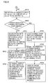
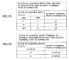
- FIGS. 7A and 7B show relations between a control terminal input of the change-over switch and a selected terminal.
- FIGS. 8 and 9 are flow charts for describing operations of selector 24 and change-over switch 36 .
- FIGS. 10A and 10B show relations between a control terminal input of the change-over switch and a selected terminal.
- selector 23 A switching operation of selector 23 shown in FIG. 3 will now be described referring to FIG. 5 to FIGS. 7A and 7B.
- step is abbreviated as SP in the drawings
- selector 23 connects an input of a1 out of three inputs of a1, a2, a3 to output Ya at a step SP 3 .
- a1 terminal of change-over switch 35 is set to a no-signal state at a step SP 8 , and a signal distributed to the radio mobile terminal by wireless from AV output Ya of selector 23 via AV communication module 1 is set to the no-signal state at a step SP 9 .
- a user of a radio communication terminal sends a selection request signal of another tuner from the radio communication terminal to the AV communication module.
- selector 23 connects an input of a2 out of three inputs of a1, a2, a3 to AV output Ya at a step SP 11 . Then, a determination is made as to whether the other selector is turning on change-over switch 36 or not at a step SP 12 . If not, selector 23 sets control input c2 of change-over switch 36 to the “H” level and releases the control of switch 35 / 37 to control input c1/c3 at a step SP 13 . At a step SP 14 , a2 of change-over switch 36 is turned on and an AV signal output of satellite tuner 17 is output to a2. The AV signal output of satellite tuner 17 is distributed to a radio mobile terminal by wireless from AV output Ya of selector 23 via AV communication module 1 at a step SP 15 .
- a2 of change-over switch 36 remains in an off-state and is set to a no-signal state at a step SP 16 .
- a signal distributed to the radio mobile terminal by wireless from AV output Ya of selector 23 via AV communication module 1 is set to the no-signal state at a step SP 17 .
- a user of a radio communication terminal sends a selection request signal of another tuner from the radio communication terminal to AV communication module 1 .
- selector 23 connects an input of a3 out of three inputs of a1, a2, a3 to AV output Ya at a step SP 19 shown in FIG. 6.
- a determination is made as to whether the other selector is turning on change-over switch 37 or not at a step SP 20 . If not, selector 23 sets control input c3 of change-over switch 37 to the “H” level and releases the control of switch 35 / 36 to control input c1/c2 at a step SP 21 .
- a3 of change-over switch 35 is turned on and an AV signal output of CATV tuner 20 is output to a3.
- the AV signal output of CATV tuner 20 is distributed to a radio mobile terminal by wireless from AV output Ya of selector 23 via AV communication module 1 at a step SP 23 .
- a3 of change-over switch 37 remains in an off-state and is set to a no-signal state at a step SP 24 .
- a signal distributed to the radio mobile terminal by wireless from AV output Ya of selector 23 via the AV communication module is set to the no-signal state at a step SP 25 .
- a user of a radio communication terminal sends a selection request signal of another tuner from the radio communication terminal to AV communication module 1 .
- Selector 24 similarly operates as shown in FIG. 8 to FIGS. 10A and 10B. As only selector 23 in FIGS. 5 - 7 A, 7 B is replaced by selector 24 and AV communication module 1 is replaced by AV communication module 2 in FIGS. 8 - 10 A, 10 B, overlapping descriptions thereof will not be repeated.
- FIG. 11 is a block diagram of an access point according to a third embodiment of the present invention.
- a tuner selection disable signal is sent from a Za terminal and a Zb terminal to AV communication modules 1 , 2 , and AV communication modules 1 , 2 send this signal to a radio terminal which is in communication by wireless.
- Other structures are similar to that in FIG. 3. With this access point 11 , the radio terminal can rapidly notice when the tuner to be selected is already used by another radio terminal and smoothly select another tuner.
- FIG. 12 is a block diagram of an access point according to a fourth embodiment of the present invention.
- AV communication module 1 is set to have a first priority and AV communication module 2 is set to have a second priority.
- AV communication module 1 detects an output signal from an output terminal V 2 of AV communication module 2 , which is the other AV communication module, at input terminal W 1 to detect whether the AV communication module is in communication with a communication terminal or not.
- V 2 of AV communication module 2 which is the other AV communication module
- Similar connection and detection are performed to each of the other AV communication modules.
- AV communication module 1 sends a signal noticing that it is not connected to a radio terminal from output terminal V 1 to input terminal W 2 of AV communication module 2 .
- each of the other AV communication modules is similarly connected and a non-connection notice signal is sent. With this, the AV communication module can recognize connected/non-connected states of the other AV communication modules.
- AV communication module 1 recognizes that it has a first priority of non-connected AV communication modules, and sends a radio terminal sense signal.
- notebook computer 12 as a radio terminal detects the signal and sends back a connection request signal to this AV communication module to start communication
- a radio terminal connection signal is originated from an output terminal (V 1 ) 45 of AV communication module 1 .
- AV communication module 2 receives this signal at an input terminal (W 2 ) 48 and recognizes that now it has the highest priority of non-connected AV communication modules, and starts to originate the radio terminal sense signal.
- PDA 14 as a radio terminal detects this signal and starts communication with the AV communication module.
- FIG. 13 is a block diagram of an access point according to a fifth embodiment of the present invention.
- a terminal detecting a control bus signal of each change-over switch is provided in each AV communication module. More specifically, an O 1 terminal, a P 1 terminal and a Q 1 terminal are provided in AV communication module 1 , while an O 2 terminal, a P 2 terminal and a Q 2 terminal are provided in AV communication module 2 .
- the tuner selected by the other AV communication module can be recognized, and this information can be sent to a radio terminal.
- the radio terminal receives this information and indicates the information on a display.
- the radio terminal can select a tuner which is not selected by seeing the indication of the information.
- FIG. 14 is a block diagram of an access point according to a sixth embodiment of the present invention.
- This embodiment includes an AV communication module controller 44 which, when further radio terminal requests the AV signal distribution while no non-communicating AV communication module is left, compares a desired channel in the requested AV signal with the channels in the AV communication modules which are already in communication, and if there is the same channel, directs to the corresponding AV communication module to divide a bandwidth of an error resending and switch the one-to-one connection to a one-to-multiple connection, and thereby increases the number of radio communication terminals that can receive AV distribution.
- a system administrator may be able to set the AV communication module which can always maintain the one-to-one connection.
- the number of radio communication terminal devices which can receive AV distribution may be increased while suppressing the interference between AV signal transmissions by increasing the transmission bandwidth by adding a 5.2 MHz band to a 2.4 GHz band as a radio frequency bandwidth to be used.
Abstract
An access point includes a gateway enabling an internet connection, a settop box selecting and outputting a video signal and an audio signal from a plurality of tuners respectively receiving broadcastings corresponding to a request signal, and an AV/LAN radio transmission module having an AV communication module for transmitting and receiving a video signal and an audio signal by wireless, a radio LAN transmission and reception module performing transmission and reception, and transmission and reception antenna, and local area radio communication and communication for a plurality of AV signal distributions are performed in frequency bands that are not overlapping one another. Therefore, a radio LAN such as the internet as well as broadcasting contents distribution can be provided to a mobile information terminal device.
Description
- 1. Field of the Invention
- The present invention relates to an access point and a radio communication system and, more specifically, to local area radio communication between an access point and a plurality of radio information terminals.
- 2. Description of the Background Art
- Local area communication between a plurality of mobile information terminal devices such as notebook-type personal computers (hereafter referred to as notebook computers) or PDAs (Personal Digital Assistants) and an access point is performed in a system as shown in FIG. 15 or 16.
- In an example shown in FIG. 15, a
gateway 32 and an AP-side radio LAN (Local Area Network)transmission module 38 are included in anaccess point 11, and local area communication via a radio LAN is performed betweenaccess point 11 andnotebook computers PDA 14. - Gateway 32 in
access point 11 has acable modem 25, an ONU (Optical Network Unit) 26 and an xDSL (Digital Subscriber Line)modem 27.Cable modem 25 is connected to a CATV (Community Antenna Television)circuit 27, while ONU 26 is connected to an FTTH (Fiber To The Home) circuit 29, andxDSL modem 27 is connected to an ads circuit 30. AP-side radioLAN transmission module 38 includes a radio LAN transmission andreception module 4 and a transmission andreception antenna 7. Transmission andreception antenna 7 is provided to perform a radio LAN communication withnotebook computers PDA 14, and each ofnotebook computers PDA 14 includes a transmission and reception antenna and a radio LAN transmission and reception module. - In this example, a radio LAN is configured between, for example, a transmission and reception antenna of
notebook computer 12 and transmission andreception antenna 7 of AP-side radioLAN transmission module 38, and communication with one ofCATV circuit 27, FTTH circuit 29 and ads circuit 30 is performed by radio LAN transmission andreception module 4 via one ofcable modem 25, ONU 26 andxDSL modem 27. - In a system shown in FIG. 16, on the other hand, an analog ground
wave reception antenna 40 is connected to aground wave tuner 15, and ground wave broadcasting is received byground wave tuner 15 and the received output is provided to an AVradio transmission module 41. AVradio transmission module 41 has anAV transmission module 1 and atransmission antenna 5. Broadcasting contents of video and audio are distributed from AVradio transmission module 41 to an AVradio reception module 42. AVradio reception module 42 includes a transmission andreception antenna 8 and an AV reception module, and outputs video and audio signals to aTV monitor 43. - As described above, a conventional system was the internet or an intranet as shown in FIG. 15 which only communicated information data, or a system as shown in FIG. 16 which only transmitted broadcasting contents of video and audio by wireless. There was no system which can provide both a radio LAN such as the internet or an intranet which communicates information data and a distribution service of broadcasting contents of video and audio in a combination of one access point and a plurality of radio information terminal devices.
- Some users, however, may desire to use the radio LAN such as the internet with their mobile information terminal devices such as notebook computers or PDAs in a cafe, an airport or the like, while other users may desire to receive the distribution of broadcasting contents with the mobile information terminal devices.
- Therefore, a main object of the present invention is to provide an access point and a radio communication system of a local area which enable radio LAN communication such as internet communication with a mobile information terminal device as well as reception of broadcasting contents distribution with the mobile information terminal device.
- Another object of the present invention is to provide broadcasting contents distribution of a system to as many mobile information terminal devices as possible by wireless within a limited bandwidth with due consideration for clearness of video and audio.
- An access point according to the present invention is provided with a gateway unit enabling an internet connection in a plurality of different circuits, a settop box unit having a tuner to receive broadcasting from each of a plurality of different media and a selector selecting and outputting a video signal and an audio signal from the tuner corresponding to a request signal, and an AV/LAN radio transmission module unit having a video and audio communication module to transmit a video signal and an audio signal from the settop box unit by wireless and receive a request signal for changing a received broadcasting channel and broadcasting media, a transmission and reception module connected to pairs of communication antennas and the gateway unit and performing transmission and reception for local area radio communication, and a pair of transmission and reception antennas.
- With this, as the local area radio communication and communication for a plurality of AV signal distributions and reception of the request signal for changing a received broadcasting channel and broadcasting media are respectively performed in frequency bands that are not overlapping one another, a local area radio communication system can be provided which enables both of radio LAN communication such as the internet communication with a mobile information terminal such as a notebook computer or a PDA brought in a cafe, an airport or the like, and distribution of broadcasting contents to the mobile information terminal.
- Furthermore, broadcasting contents distribution of the system can be provided to as many information terminals as possible by wireless within a limited bandwidth with due consideration for clearness of video and audio.
- The foregoing and other objects, features, aspects and advantages of the present invention will become more apparent from the following detailed description of the present invention when taken in conjunction with the accompanying drawings.
- FIG. 1 is a block diagram of an access point according to a first embodiment of the present invention.
- FIGS. 2A-2C are block diagrams of notebook computers and a PDA configuring a local area communication system with the access point shown in FIG. 1.
- FIG. 3 is a block diagram of a second embodiment of an access point.
- FIG. 4 is a specific circuit diagram of a selector shown in FIG. 3.
- FIG. 5 is a flow chart for describing operations of a selector and a change-over switch.
- FIG. 6 is a flow chart for describing operations of a selector and a change-over switch.
- FIGS. 7A and 7B are tables indicating relations between a control terminal input of a change-over switch and a selected terminal.
- FIG. 8 is a flow chart for describing operations of a selector and a change-over switch.
- FIG. 9 is a flow chart for describing operations of a selector and a change-over switch.
- FIGS. 10A and 10B show relations between a control terminal input of a change-over switch and a selected terminal.
- FIG. 11 is a block diagram of an access point according to a third embodiment of the present invention.
- FIG. 12 is a block diagram of an access point according to a fourth embodiment of the present invention.
- FIG. 13 is a block diagram of an access point according to a fifth embodiment of the present invention.
- FIG. 14 is a block diagram of an access point according to a sixth embodiment of the present invention.
- FIG. 15 is a block diagram of a conventional access point including a gateway and an AP-side radio LAN transmission module.
- FIG. 16 is a block diagram of a conventional system transmitting only broadcasting contents of video and audio by wireless.
- FIG. 1 is a block diagram of an access point according to a first embodiment of the present invention, and FIGS. 2A-2C are block diagrams of notebook computers and a PDA configuring a local area communication system with the access point shown in FIG. 1.
-
Access point 11 shown in FIG. 1 configures a local area communication system with one ofnotebook computers PDA 14 shown in FIGS. 2A-2C via a radio LAN using a frequency band of 2.4 GHz. - In FIG. 1,
access point 11 is mainly formed with three portions as described below. A first portion thereof includesgateway 32 enabling an internet connection in a plurality of different circuits, while a second portion includes asettop box 33 receiving a plurality of different broadcastings and selecting from the received plurality of broadcastings corresponding to a request signal to output an AV signal, and a third portion includes a radio LAN transmission and reception unit connected togateway 32 and performing transmission and reception as a radio LAN of 2.4 GHz and an access point-side AV/LANradio transmission module 34 including a plurality of AV communication units connected tosettop box 33 of the second portion to transmit an AV output signal ofsettop box 33 by wireless of a 2.4 GHz band and receive a received broadcasting channel change signal and a broadcasting media change signal by wireless of a 2.4 GHz band. - Herein, the radio LAN transmission and reception unit of access point-side AV/LAN
radio transmission module 34 includes radio LAN transmission andreception module 4 as a signal processing unit and transmission andreception antenna 7 of an antenna unit, and the plurality of AV communication units also include pairs ofAV communication modules reception antennas - To enable connections to multiple kinds of circuits, that is, to CATV 28, FTTH 29 and ads 30,
gateway 32 includescable modem 25 for connection to CATV 28, ONU 26 for connection to FTTH 29 of optical fiber communication, andxDSL modem 27 for connection to ads 30 (a generic name for ADSL, SDSL and VDSL). To enable reception of a plurality of different broadcasting media,settop box 33 includes analog or digitalground wave tuners satellite tuners CATV tuners selector 23 to select one of outputs ofground wave tuner 15,satellite tuner 17 andCATV tuner 19, and aselector 24 to select one of outputs ofground wave tuner 16,satellite tuner 18 andCATV tuner 20. An analog/digital groundwave reception antenna 21 is connected toground wave tuners broadcasting reception antenna 22 is connected tosatellite tuners - Though the example shown in FIG. 1 includes all of
cable modem 25, ONU 26, xDSL 30,ground wave tuner 15/16,satellite tuner 17/18, andCATV tuner 19/20, the present invention is not limited to this and any of the elements may be eliminated. - Each of
notebook computers reception antenna 8, aswitching circuit 9, anAV communication module 3, and a radio LAN transmission andreception module 10.PDA 14 includes transmission andreception antenna 8,switching circuit 9,AV communication module 3, and radio LAN transmission andreception module 10. Thesenotebook computers PDA 14 are connected toaccess point 11 via a radio LAN or an AV transmission line. - Operations in this embodiment will now be described. First, a user brings a radio terminal, which is any of
notebook computers PDA 14, in a communication area of the access point and, after starting the radio terminal, selects whether to receive AV signal distribution of broadcasting contents or to use a radio LAN by operating the radio terminal. In the radio terminal, switchingcircuit 9 starts one ofAV communication module 3 and radio LAN transmission andreception module 10 based on this selection information. - When the radio LAN is selected, radio LAN transmission and
reception module 10 is started, and radio LAN transmission andreception module 10 receives a radio terminal sense signal originated from transmission andreception antenna 7 by radio LAN transmission andreception module 4 in AV/LANradio transmission module 34 of a side ofaccess point 11, and sends back a radio LAN connection request signal by wireless via transmission andreception antenna 8 to start radio LAN communication. - When the AV signal distribution is selected,
AV communication module 3 of the radio terminal is started, andAV communication module 3 receives a radio terminal sense signal originated from transmission andreception antenna AV communication modules radio transmission module 34 of a side ofaccess point 11, and sends back an AV signal distribution request signal by wireless via transmission andreception antenna 8 to start communication. When the communication is started, a tuner can first be selected. - A list of tuners is sent from
AV communication module AV communication module 3 based on the received list, andAV communication module controls selector - This distribution is continued until a change request signal for the selected tuner or a communication termination request signal is originated from the radio terminal. Change of a channel in the selected tuner is implemented by sending a channel change request signal from the radio terminal side to access point-side
AV communication module - In FIGS. 2A-2C, a situation is shown wherein
notebook computer 12 communicates with access point-sideAV communication module 1 shown in FIG. 1 to receive the AV signal distribution, whilenotebook computer 13 communicates with access point-side radio LAN transmission andreception module 4 to perform the radio LAN communication, andPDA 14 communicates with access point-sideAV communication module 2 to receive the AV signal distribution. - In this embodiment, when there are a plurality of AV access point-side AV communication modules which are not in communication with the radio terminals, radio terminal sense signals are originated from all of these AV communication modules. After the AV communication module is started, the radio terminal senses by successively switching a reception frequency bandwidth in a 2.4 GHz band and starts communication with the AV communication module originating the radio terminal sense signal which can first be received. It cannot be predicted which AV communication module is to be connected, because it also depends on a communication environment at that time.
- On the contrary, priorities may previously be assigned to AV communication modules to make an AV communication module having the highest priority of unconnected AV communication modules communicate with the radio terminal. In this situation, unconnected AV communication modules first transmit radio terminal sense signals including priorities thereof. The radio terminal, on the other hand, sends back the AV signal distribution request signal to the access point-side AV communication module originating a signal including the highest priority of the received priority-added radio terminal sense signals to start communication.
- By configuring the local area communication system as such, a local area radio communication system can be provided which enables radio LAN communication such as the internet communication with
notebook computers PDA 14 as well as reception of broadcasting contents distribution withnotebook computers PDA 14. In addition, broadcasting contents distribution can be provided to asmany notebook computers PDA 14 as possible by wireless within a limited bandwidth with due consideration for clearness of video and audio. - FIG. 3 is a block diagram of a second embodiment of an access point. Though the embodiment shown in FIG. 1 includes two tuners of each kind for respective
AV communication modules settop box 33, the embodiment shown in FIG. 3 includes only each ones ofground wave tuner 15,satellite tuner 17 andCATV tuner 19. Change-over switches 35-37 are provided to switch outputs ofrespective tuners selectors - An AV output and channel change signal input transmission path of
ground wave tuner 15 is connected to a d1 terminal of change-over switch 35. Change-overswitch 35 connects the d1 terminal to an a1 terminal when a control input c1 is set to the “L” level, and connects the d1 terminal to a b1 terminal when control input c1 is set to the “H” level. The a1 terminal is connected toselector 23, while the b1 terminal is connected toselector 24. A control terminal c1 is connected to a three-state output outputting an “H”/“L” level signal of change-over switch control for bothselectors - An output from each selector to this bus line is such that, while
selector 23 is outputting a control signal of the “H” level,selector 24 sets a control signal output to a high impedance state and keeps the change-over switch control bus line at the “H” level. With this, al-side of change-over switch 35 is turned on, and an AV signal output and channel change signal transmission path ofground wave tuner 15 is input toselector 23. - While
selector 24 is outputting a control signal of the “L” level,selector 23 sets a control signal output to a high impedance state and keeps the change-over switch control bus line at the “L” level. With this, b1-side of change-over switch 35 is turned on, and the AV signal output and channel change signal transmission path ofground wave tuner 15 is input toselector 24. An AV output and channel change signal input transmission path ofsatellite tuner 17 is connected to a d2 terminal of change-over switch 36. Change-overswitch 36 connects the d2 terminal to an a2 terminal when a control input c2 is set to the “L” level, and connects the d2 terminal toa b 2 terminal when control input c2 is set to the “H” level. The a2 terminal is connected toselector 23 as the a1 terminal, while the b2 terminal is connected toselector 24. - Similar to control terminal cl, a control terminal c2 is also connected to a three-state output outputting an “H”/“L” level signal of change-over switch control for both
selectors selector 23 is outputting a control signal of the “H” level,selector 24 sets a control signal output to a high impedance state and keeps the change-over switch control bus line at the “H” level. With this, a2-side of change-over switch 36 is turned on, and an AV signal output and channel change signal transmission path ofsatellite tuner 17 is input toselector 23. - While
selector 24 is outputting a control signal of the “L” level,selector 23 sets a control signal output to a high impedance state and keeps the change-over switch control bus line at the “L” level. With this, b2-side of change-over switch 36 is turned on, and the AV signal output and channel change signal transmission path ofsatellite tuner 17 is input toselector 24. Change-overswitch 37 switches an AV output and channel change signal ofCATV tuner 19 to connect a d3 terminal to an a3 terminal when a control input c3 connected to the d3 terminal is set to the “L” level, and connect the d3 terminal to a b3 terminal when control input c3 is set to the “H” level. The a3 terminal is connected toselector 23 as the a1/a2 terminal, while the b3 terminal is connected toselector 24 as the b1/b2 terminal. Similar to the c1/c2 terminal, a control terminal c3 is also connected to a three-state output outputting an “H”/“L” level signal of change-over switch control for bothselectors CATV tuner 19 is to be connected corresponding to control signal outputs ofselectors - In addition, an AV signal output and channel change signal input terminal Ya of
selector 23 and an AV signal output and channel change signal input terminal Yb ofselector 24 as well as SW1/SW2 terminals inputting a control signal for selecting a tuner from the AV communication module-side are connected toAV communication modules AV communication modules selector 23 is determined, and one of the terminals of the change-over switches b1/b2/b3 to be connected to AV signal output and channel change signal input terminal Yb ofselector 24 is determined. Concurrently with this selection of the change-over switch, each ofselectors - If the control bus is already controlled by the other selector, the change-over switch remains connected to a side of the other selector controlling the control bus.
- FIG. 4 is a specific circuit diagram of the selector shown in FIG. 3. In FIG. 4, the selector is formed with generalized circuits including three-input video switches 201, 202, D
type latch circuits circuits - FIGS. 5 and 6 are flow charts for describing operations of
selector 23 and change-overswitch 35. FIGS. 7A and 7B show relations between a control terminal input of the change-over switch and a selected terminal. FIGS. 8 and 9 are flow charts for describing operations ofselector 24 and change-overswitch 36. FIGS. 10A and 10B show relations between a control terminal input of the change-over switch and a selected terminal. - A switching operation of
selector 23 shown in FIG. 3 will now be described referring to FIG. 5 to FIGS. 7A and 7B. When SW2 terminal ofselector 23 is determined as not being at the “H” level at a step SP1 (“step” is abbreviated as SP in the drawings) shown in FIG. 5, and when SW1 terminal ofselector 23 is determined as not being at the “H” level at a step SP2,selector 23 connects an input of a1 out of three inputs of a1, a2, a3 to output Ya at a step SP3. - A determination is made as to whether the
other selector 24 is turning on change-over switch 35 or not at a step SP4. If not,selector 23 sets control input c1 of change-over switch 35 to the “H” level and releases the control ofswitch 36/37 to control input c2/c3 at a step SP5. At a step SP6, a1 terminal of change-over switch 35 is turned on and an AV signal output ofground wave tuner 15 is output to a1 terminal. The AV signal ofground wave tuner 15 is distributed to a radio mobile terminal by wireless from AV output Ya ofselector 23 viaAV communication module 1. - If the other selector is turning on change-
over switch 35 at step SP4, a1 terminal of change-over switch 35 is set to a no-signal state at a step SP8, and a signal distributed to the radio mobile terminal by wireless from AV output Ya ofselector 23 viaAV communication module 1 is set to the no-signal state at a step SP9. At a step SP10, a user of a radio communication terminal sends a selection request signal of another tuner from the radio communication terminal to the AV communication module. - If SW1 terminal of
selector 23 is at the “H” level at the aforementioned step SP2,selector 23 connects an input of a2 out of three inputs of a1, a2, a3 to AV output Ya at a step SP11. Then, a determination is made as to whether the other selector is turning on change-over switch 36 or not at a step SP12. If not,selector 23 sets control input c2 of change-over switch 36 to the “H” level and releases the control ofswitch 35/37 to control input c1/c3 at a step SP13. At a step SP14, a2 of change-over switch 36 is turned on and an AV signal output ofsatellite tuner 17 is output to a2. The AV signal output ofsatellite tuner 17 is distributed to a radio mobile terminal by wireless from AV output Ya ofselector 23 viaAV communication module 1 at astep SP 15. - If the other selector is turning on change-
over switch 36 at the aforementioned step SP12, a2 of change-over switch 36 remains in an off-state and is set to a no-signal state at a step SP16. A signal distributed to the radio mobile terminal by wireless from AV output Ya ofselector 23 viaAV communication module 1 is set to the no-signal state at a step SP17. At a step SP18, a user of a radio communication terminal sends a selection request signal of another tuner from the radio communication terminal toAV communication module 1. - If SW2 terminal of
selector 23 is determined as being at the “H” level at the aforementioned step SP1,selector 23 connects an input of a3 out of three inputs of a1, a2, a3 to AV output Ya at a step SP19 shown in FIG. 6. A determination is made as to whether the other selector is turning on change-over switch 37 or not at a step SP20. If not,selector 23 sets control input c3 of change-over switch 37 to the “H” level and releases the control ofswitch 35/36 to control input c1/c2 at a step SP21. At a step SP22, a3 of change-over switch 35 is turned on and an AV signal output ofCATV tuner 20 is output to a3. The AV signal output ofCATV tuner 20 is distributed to a radio mobile terminal by wireless from AV output Ya ofselector 23 viaAV communication module 1 at astep SP 23. - If the other selector is turning on change-
over switch 37 at the aforementioned step SP20, a3 of change-over switch 37 remains in an off-state and is set to a no-signal state at a step SP24. A signal distributed to the radio mobile terminal by wireless from AV output Ya ofselector 23 via the AV communication module is set to the no-signal state at a step SP25. At a step SP26, a user of a radio communication terminal sends a selection request signal of another tuner from the radio communication terminal toAV communication module 1. -
Selector 24 similarly operates as shown in FIG. 8 to FIGS. 10A and 10B. As onlyselector 23 in FIGS. 5-7A, 7B is replaced byselector 24 andAV communication module 1 is replaced byAV communication module 2 in FIGS. 8-10A, 10B, overlapping descriptions thereof will not be repeated. - FIG. 11 is a block diagram of an access point according to a third embodiment of the present invention. In the embodiment shown in FIG. 11, when the tuner to be selected is already used by the other selector and the change-over switch cannot be turned, a tuner selection disable signal is sent from a Za terminal and a Zb terminal to
AV communication modules AV communication modules access point 11, the radio terminal can rapidly notice when the tuner to be selected is already used by another radio terminal and smoothly select another tuner. - FIG. 12 is a block diagram of an access point according to a fourth embodiment of the present invention. In this embodiment, among a plurality of AV communication modules having priorities assigned thereto in
access point 11, only an AV communication module having the highest priority of AV communication modules which are not connected with radio terminals originates a radio terminal sense signal. A situation will be described whereinAV communication module 1 is set to have a first priority andAV communication module 2 is set to have a second priority. -
AV communication module 1 detects an output signal from an output terminal V2 ofAV communication module 2, which is the other AV communication module, at input terminal W1 to detect whether the AV communication module is in communication with a communication terminal or not. When three or more AV communication modules are provided, similar connection and detection are performed to each of the other AV communication modules. At the same time,AV communication module 1 sends a signal noticing that it is not connected to a radio terminal from output terminal V1 to input terminal W2 ofAV communication module 2. When three or more AV communication modules are provided, each of the other AV communication modules is similarly connected and a non-connection notice signal is sent. With this, the AV communication module can recognize connected/non-connected states of the other AV communication modules. - Then,
AV communication module 1 recognizes that it has a first priority of non-connected AV communication modules, and sends a radio terminal sense signal. Whennotebook computer 12 as a radio terminal detects the signal and sends back a connection request signal to this AV communication module to start communication, a radio terminal connection signal is originated from an output terminal (V1) 45 ofAV communication module 1.AV communication module 2 receives this signal at an input terminal (W2) 48 and recognizes that now it has the highest priority of non-connected AV communication modules, and starts to originate the radio terminal sense signal.PDA 14 as a radio terminal detects this signal and starts communication with the AV communication module. By making only one of non-connected AV communication modules originate the radio terminal sense signal, interference and power consumption can be reduced. - FIG. 13 is a block diagram of an access point according to a fifth embodiment of the present invention. In this embodiment, a terminal detecting a control bus signal of each change-over switch is provided in each AV communication module. More specifically, an O 1 terminal, a P1 terminal and a Q1 terminal are provided in
AV communication module 1, while an O2 terminal, a P2 terminal and a Q2 terminal are provided inAV communication module 2. With this, the tuner selected by the other AV communication module can be recognized, and this information can be sent to a radio terminal. The radio terminal receives this information and indicates the information on a display. The radio terminal can select a tuner which is not selected by seeing the indication of the information. - With this, by
AV communication module 1 continuing a one-to-one connection with a radio terminal until no non-communicating AV communication module is left, a transmission system of resending when an error occurs as indicated in Japanese Patent Application No. 2000-312890 can be implemented. - FIG. 14 is a block diagram of an access point according to a sixth embodiment of the present invention. This embodiment includes an AV
communication module controller 44 which, when further radio terminal requests the AV signal distribution while no non-communicating AV communication module is left, compares a desired channel in the requested AV signal with the channels in the AV communication modules which are already in communication, and if there is the same channel, directs to the corresponding AV communication module to divide a bandwidth of an error resending and switch the one-to-one connection to a one-to-multiple connection, and thereby increases the number of radio communication terminals that can receive AV distribution. - It is to be noted that, a system administrator may be able to set the AV communication module which can always maintain the one-to-one connection.
- It is also possible to reduce interference between AV signal transmissions by ensuring frequency bandwidths used by a plurality of AV communication modules in separate bandwidths within a 2.4 GHz band, and ensuring a transmission bandwidth of a radio LAN therebetween.
- Further, the number of radio communication terminal devices which can receive AV distribution may be increased while suppressing the interference between AV signal transmissions by increasing the transmission bandwidth by adding a 5.2 MHz band to a 2.4 GHz band as a radio frequency bandwidth to be used.
- Although the present invention has been described and illustrated in detail, it is clearly understood that the same is by way of illustration and example only and is not to be taken by way of limitation, the spirit and scope of the present invention being limited only by the terms of the appended claims.
Claims (18)
1. An access point for local area radio communication with a plurality of radio information terminal devices, comprising:
a gateway unit enabling an internet connection in a plurality of different circuits;
a settop box unit having a tuner to receive broadcasting from each of a plurality of different media and a selector selecting and outputting a video signal and an audio signal from said tuner corresponding to a request signal; and
an AV/LAN radio transmission unit having a video and audio communication module to transmit a video signal and an audio signal output from said settop box unit by wireless and receive a request signal for changing a received broadcasting channel and broadcasting media, a transmission and reception module connected to pairs of communication antennas and said gateway unit and performing transmission and reception for local area radio communication, and a pair of transmission and reception antennas; wherein
said local area radio communication and communication for a plurality of said AV signal distributions and reception of a request signal for changing a received broadcasting channel and broadcasting media are respectively performed in frequency bands that are not overlapping one another.
2. The access point according to claim 1 , wherein
when reception of AV signal distribution is requested from said radio information terminal device, a connection with the radio information terminal device is established according to priorities assigned to a plurality of said AV communication modules.
3. The access point according to claim 2 , further comprising:
an output terminal provided corresponding to number of all other AV communication module and noticing that an AV signal is distributed to said radio information terminal device in said plurality of AV communication modules;
an input terminal receiving a signal noticing that an AV signal is distributed from all other AV communication module; and
means for connecting said input terminal and said output terminal, allowing only an AV communication module having the highest priority of AV communication modules not connected to said radio information terminal device to originate a radio signal sensing a radio information terminal device, and allowing the AV communication module originating the sense signal to start connection with a radio information terminal device and to concurrently send a signal noticing that it is connected to other AV communication module.
4. The access point according to claim 2 , wherein
in a plurality of AV communication modules having said priorities allocated thereto, the lowest priority is allocated when distribution of an AV signal to said radio information terminal device is ended.
5. The access point according to claim 1 , comprising:
all or a part of a cable modem, an optical network unit and an xDSL modem to enable said gateway unit to establish an internet connection in said plurality of different circuits; and
all or a part of an analog ground wave tuner, a digital ground wave tuner, a satellite broadcasting tuner, and a CATV tuner to enable reception of a plurality of different broadcasting media.
6. The access point according to claim 1 , wherein
number of said tuners for each broadcasting media included is same as number of said AV communication modules, and
said selector selects a tuner corresponding to desired broadcasting media to be distributed among said plurality of tuners and connects with said AV communication module.
7. The access point according to claim 1 , having
a change-over switch switching connections between an AV output portion of a tuner provided for each of said different broadcasting media and said plurality of selectors, wherein
each said selector operates said change-over switch relating to a certain tuner corresponding to a tuner selection request signal from said AV communication module when other selector is not operating, and enables switching of a change-over switch relating to other tuner from other selector.
8. The access point according to claim 7 , wherein
when said selector cannot select a certain tuner corresponding to said tuner selection request signal because other tuner has already selected the tuner, said AV communication module detects a selection disable signal from the selector and notices to a radio information communication terminal device in communication that the tuner is used by other user and cannot be selected.
9. A radio communication system, comprising:
an access point according to claim 1; and
one or more mobile information terminal device including an AV communication module receiving an AV signal transmitted from said access point and transmitting a request signal for changing a received broadcasting channel and broadcasting media, a local area radio communication transmission and reception module transmitting and receiving local area radio communication data to and from said access point, switching means for selectively validating communication of one of the AV communication module and the local area radio communication transmission and reception module, and an AV/LAN radio transmission module having an antenna for transmission and reception transmitting a signal from a module validated by the switching means and receiving a radio signal; wherein
a local area radio communication service and a broadcasting contents distribution service provided from the access point can be switched and received corresponding to a request from said mobile information terminal device.
10. The radio communication system according to claim 9 , wherein
each of the plurality of AV communication modules monitors all selection state of said change-over switch of each said tuner, sends information of selectable tuner or non-selectable tuner by wireless to a radio communication terminal receiving radio distribution of an AV signal, and indicates the information on a display of the radio terminal.
11. The radio communication system according to claim 9 , wherein
when connection to said access point is attempted from said mobile radio terminal device after a determination is made whether to perform said local radio communication or to receive broadcasting contents distribution, said access point is connected with said radio LAN transmission and reception module when the local area radio communication is performed and is connected to an AV communication module that is not connected to other mobile information terminal among a plurality of AV communication modules when the broadcasting contents distribution is requested, the AV communication module is not connected to other mobile information terminal until a connection is ended by the connected mobile information terminal, and a selector keeps a connection of said tuner connected to the mobile information terminal device to prevent connection to other AV communication module until the mobile information terminal requests to change connected broadcasting media.
12. The radio communication system according to claim 9 , wherein
a plurality of said AV communication modules in said access point successively originate signals noticing a non-communication state continuously or at regular intervals when not communicating with said mobile information terminal device, and
said mobile information terminal device finds a non-communicating module from the plurality of AV communication modules based on said signal noticing the non-communication state and starts communication, and the AV communication module in said access point concurrently stops originating the non-communication signal to prevent access from other mobile information terminal device.
13. The radio communication system according to claim 12 , wherein
said plurality of AV communication modules in said access point successively originate signals noticing a non-communication state continuously or at regular intervals when not communicating with said mobile information terminal device, and
said mobile information terminal device finds a non-communicating module from the plurality of AV communication modules based on said signal noticing the non-communication state and starts communication, and the AV communication module in said access point concurrently stops originating the non-communication signal to prevent access from other mobile information terminal device until no non-communicating AV communication module is left in said access point, and said mobile information terminal device and said AV communication module maintain a one-to-one connection.
14. The radio communication system according to claim 12 , wherein
a transmission system of resending when an error occurs is used as radio transmission of said AV signal, and transmission from an AV communication module already in communication in said access point is not received by said plurality of radio mobile information terminal devices even when the same video is requested, but other non-communicating module is allocated to keep high-quality AV signal transmission with less errors.
15. The radio communication system according to claim 12 , comprising
an AV communication module controller that, when new one of said radio mobile information terminal device requests further AV signal distribution while no non-communicating said AV communication module is left, compares a desired channel in a requested AV signal with a channel in the AV communication module already in communication, and if there is the same channel, directs to the corresponding AV communication module to divide a bandwidth of an error resending and switch a one-to-one connection to a one-to-multiple connection, wherein
number of radio mobile information terminal devices that can receive broadcasting contents from said access point increases.
16. The radio communication system according to claim 15 , wherein
a system administrator can previously set a part of said plurality of AV communication modules in said access point as an AV communication module maintaining a one-to-one connection state to provide broadcasting contents only to a specific person of users each receiving the broadcasting contents with said radio information terminal device.
17. The radio communication system according to claim 9 , wherein
ensured bandwidths of said AV signal transmission are arranged in separate frequency bandwidths, and a transmission bandwidth of local area radio communication is allocated in a frequency bandwidth therebetween to reduce interference between said AV signals.
18. The radio communication system according to claim 9 , wherein
a transmission bandwidth of radio to be used is further increased, and a bandwidth used for AV signal transmission is allocated so as to always have the largest bandwidth space.
Applications Claiming Priority (2)
| Application Number | Priority Date | Filing Date | Title |
|---|---|---|---|
| JP2002101651A JP3964248B2 (en) | 2002-04-03 | 2002-04-03 | Access point and wireless communication system |
| JP2002-101651(P) | 2002-04-03 |
Publications (1)
| Publication Number | Publication Date |
|---|---|
| US20030192055A1 true US20030192055A1 (en) | 2003-10-09 |
Family
ID=28672122
Family Applications (1)
| Application Number | Title | Priority Date | Filing Date |
|---|---|---|---|
| US10/375,002 Abandoned US20030192055A1 (en) | 2002-04-03 | 2003-02-28 | Access point for local area radio communication and radio communication system using the same |
Country Status (2)
| Country | Link |
|---|---|
| US (1) | US20030192055A1 (en) |
| JP (1) | JP3964248B2 (en) |
Cited By (23)
| Publication number | Priority date | Publication date | Assignee | Title |
|---|---|---|---|---|
| US20030219008A1 (en) * | 2002-05-20 | 2003-11-27 | Scott Hrastar | System and method for wireless lan dynamic channel change with honeypot trap |
| US20040157624A1 (en) * | 2002-05-20 | 2004-08-12 | Hrastar Scott E. | Systems and methods for adaptive location tracking |
| US20050152323A1 (en) * | 2004-01-12 | 2005-07-14 | Vincent Bonnassieux | Plug-in Wi-Fi access point device and system |
| US20050152306A1 (en) * | 2004-01-12 | 2005-07-14 | Vincent Bonnassieux | Wi-Fi access point device and system |
| WO2005062975A2 (en) | 2003-12-23 | 2005-07-14 | Digital Networks North America, Inc. | Method and apparatus for distributing media in a pay per play architecture with remote playback within an enterprise |
| US20050174961A1 (en) * | 2004-02-06 | 2005-08-11 | Hrastar Scott E. | Systems and methods for adaptive monitoring with bandwidth constraints |
| US20070254714A1 (en) * | 2006-05-01 | 2007-11-01 | Martich Mark E | Wireless access point |
| US7715800B2 (en) | 2006-01-13 | 2010-05-11 | Airdefense, Inc. | Systems and methods for wireless intrusion detection using spectral analysis |
| US7779476B2 (en) | 2002-05-20 | 2010-08-17 | Airdefense, Inc. | Active defense against wireless intruders |
| US20100296496A1 (en) * | 2009-05-19 | 2010-11-25 | Amit Sinha | Systems and methods for concurrent wireless local area network access and sensing |
| US7971251B2 (en) | 2006-03-17 | 2011-06-28 | Airdefense, Inc. | Systems and methods for wireless security using distributed collaboration of wireless clients |
| US7970013B2 (en) | 2006-06-16 | 2011-06-28 | Airdefense, Inc. | Systems and methods for wireless network content filtering |
| US20110179462A1 (en) * | 2008-08-05 | 2011-07-21 | Seiji Kubo | Communication device, communication method, recording medium, and integrated circuit |
| US8196199B2 (en) | 2004-10-19 | 2012-06-05 | Airdefense, Inc. | Personal wireless monitoring agent |
| US20120163201A1 (en) * | 2010-12-27 | 2012-06-28 | Belair Networks | Cable modem with dual automatic attenuation |
| US8281392B2 (en) | 2006-08-11 | 2012-10-02 | Airdefense, Inc. | Methods and systems for wired equivalent privacy and Wi-Fi protected access protection |
| WO2013063134A1 (en) * | 2011-10-26 | 2013-05-02 | Aereo, Inc. | Method and system for assigning antennas in dense array |
| US8787975B2 (en) | 2010-11-18 | 2014-07-22 | Aereo, Inc. | Antenna system with individually addressable elements in dense array |
| US20150106855A1 (en) * | 2009-03-03 | 2015-04-16 | Mobilitie, Llc | System and method for multi-channel wifi video streaming |
| US9258575B2 (en) | 2011-02-18 | 2016-02-09 | Charter Communications Operating, Llc | Cloud based location shifting service |
| US20160323634A1 (en) * | 2015-04-30 | 2016-11-03 | Advanced Digital Broadcast S.A. | System and a method for distributing content via static channel assignment in a mobile content gateway |
| US10051293B2 (en) | 2009-03-03 | 2018-08-14 | Mobilitie, Llc | System and method for operation of a temporary control facility for video distribution in a venue |
| US10616619B2 (en) | 2009-03-03 | 2020-04-07 | Mobilitie, Llc | System and method for multi-channel WiFi video streaming |
Families Citing this family (3)
| Publication number | Priority date | Publication date | Assignee | Title |
|---|---|---|---|---|
| JP4307340B2 (en) * | 2004-06-25 | 2009-08-05 | シャープ株式会社 | Digital broadcast receiver having a plurality of receivers |
| KR101106750B1 (en) * | 2005-01-26 | 2012-01-18 | 삼성전자주식회사 | Apparatus and method for providing digital multimedia broadcasting service using wireless network |
| JP2015149655A (en) * | 2014-02-07 | 2015-08-20 | 船井電機株式会社 | television broadcast receiver |
Citations (11)
| Publication number | Priority date | Publication date | Assignee | Title |
|---|---|---|---|---|
| US5014350A (en) * | 1988-04-28 | 1991-05-07 | Sanyo Electric Co., Ltd. | Apparatus for and method of improving the AFC of a television broadcast satellite receiver |
| US5708961A (en) * | 1995-05-01 | 1998-01-13 | Bell Atlantic Network Services, Inc. | Wireless on-premises video distribution using digital multiplexing |
| US5930247A (en) * | 1997-02-27 | 1999-07-27 | At&T Corp. | Broadband data reception system for WorldNet™ access |
| US6094237A (en) * | 1996-05-16 | 2000-07-25 | Sharp Kabushiki Kaisha | Channel selecting system |
| US6182126B1 (en) * | 1994-10-12 | 2001-01-30 | Touchtunes Music Corporation | Home digital audiovisual information recording and playback system |
| US20020071401A1 (en) * | 2000-09-19 | 2002-06-13 | Katsuo Nire | Command processing method and radio communication apparatus |
| US20020126696A1 (en) * | 1997-05-12 | 2002-09-12 | Victor Company Of Japan, Ltd. | Communication system and circuit controller |
| US20040255326A1 (en) * | 2000-12-28 | 2004-12-16 | John Alson Hicks | Digital residential entertainment system |
| US6889385B1 (en) * | 2000-01-14 | 2005-05-03 | Terayon Communication Systems, Inc | Home network for receiving video-on-demand and other requested programs and services |
| US20060085717A1 (en) * | 2000-10-13 | 2006-04-20 | Tomonobu Tomaru | Communications method, communications apparatus and communications system using same communications apparatus |
| US7171677B1 (en) * | 1998-02-25 | 2007-01-30 | Nec Corporation | Broadcast storing and displaying apparatus and video apparatus |
-
2002
- 2002-04-03 JP JP2002101651A patent/JP3964248B2/en not_active Expired - Fee Related
-
2003
- 2003-02-28 US US10/375,002 patent/US20030192055A1/en not_active Abandoned
Patent Citations (12)
| Publication number | Priority date | Publication date | Assignee | Title |
|---|---|---|---|---|
| US5014350A (en) * | 1988-04-28 | 1991-05-07 | Sanyo Electric Co., Ltd. | Apparatus for and method of improving the AFC of a television broadcast satellite receiver |
| US6182126B1 (en) * | 1994-10-12 | 2001-01-30 | Touchtunes Music Corporation | Home digital audiovisual information recording and playback system |
| US20030074666A1 (en) * | 1994-10-12 | 2003-04-17 | Touchtunes Music Corporation | Audiovisual distribution system |
| US5708961A (en) * | 1995-05-01 | 1998-01-13 | Bell Atlantic Network Services, Inc. | Wireless on-premises video distribution using digital multiplexing |
| US6094237A (en) * | 1996-05-16 | 2000-07-25 | Sharp Kabushiki Kaisha | Channel selecting system |
| US5930247A (en) * | 1997-02-27 | 1999-07-27 | At&T Corp. | Broadband data reception system for WorldNet™ access |
| US20020126696A1 (en) * | 1997-05-12 | 2002-09-12 | Victor Company Of Japan, Ltd. | Communication system and circuit controller |
| US7171677B1 (en) * | 1998-02-25 | 2007-01-30 | Nec Corporation | Broadcast storing and displaying apparatus and video apparatus |
| US6889385B1 (en) * | 2000-01-14 | 2005-05-03 | Terayon Communication Systems, Inc | Home network for receiving video-on-demand and other requested programs and services |
| US20020071401A1 (en) * | 2000-09-19 | 2002-06-13 | Katsuo Nire | Command processing method and radio communication apparatus |
| US20060085717A1 (en) * | 2000-10-13 | 2006-04-20 | Tomonobu Tomaru | Communications method, communications apparatus and communications system using same communications apparatus |
| US20040255326A1 (en) * | 2000-12-28 | 2004-12-16 | John Alson Hicks | Digital residential entertainment system |
Cited By (46)
| Publication number | Priority date | Publication date | Assignee | Title |
|---|---|---|---|---|
| US20030219008A1 (en) * | 2002-05-20 | 2003-11-27 | Scott Hrastar | System and method for wireless lan dynamic channel change with honeypot trap |
| US20040157624A1 (en) * | 2002-05-20 | 2004-08-12 | Hrastar Scott E. | Systems and methods for adaptive location tracking |
| US8060939B2 (en) | 2002-05-20 | 2011-11-15 | Airdefense, Inc. | Method and system for securing wireless local area networks |
| US7779476B2 (en) | 2002-05-20 | 2010-08-17 | Airdefense, Inc. | Active defense against wireless intruders |
| US7042852B2 (en) * | 2002-05-20 | 2006-05-09 | Airdefense, Inc. | System and method for wireless LAN dynamic channel change with honeypot trap |
| US9160976B2 (en) | 2003-12-23 | 2015-10-13 | The Directv Group, Inc. | Method and apparatus for distributing media in a pay per play architecture with remote playback within an enterprise |
| EP1711154A4 (en) * | 2003-12-23 | 2011-11-30 | Directv Group Inc | Method and apparatus for distributing media in a pay per play architecture with remote playback within an enterprise |
| WO2005062975A2 (en) | 2003-12-23 | 2005-07-14 | Digital Networks North America, Inc. | Method and apparatus for distributing media in a pay per play architecture with remote playback within an enterprise |
| US20050283791A1 (en) * | 2003-12-23 | 2005-12-22 | Digital Networks North America, Inc. | Method and apparatus for distributing media in a pay per play architecture with remote playback within an enterprise |
| EP1711154A2 (en) * | 2003-12-23 | 2006-10-18 | Digital Networks North America, Inc. | Method and apparatus for distributing media in a pay per play architecture with remote playback within an enterprise |
| WO2005069757A3 (en) * | 2004-01-12 | 2009-03-26 | Ortronics Inc | Wi-access point device and system |
| US20050152306A1 (en) * | 2004-01-12 | 2005-07-14 | Vincent Bonnassieux | Wi-Fi access point device and system |
| US20050152323A1 (en) * | 2004-01-12 | 2005-07-14 | Vincent Bonnassieux | Plug-in Wi-Fi access point device and system |
| WO2005069757A2 (en) * | 2004-01-12 | 2005-08-04 | Ortronics, Inc. | Wi-access point device and system |
| US7785138B2 (en) | 2004-01-12 | 2010-08-31 | Ortronics, Inc. | Wireless access point installation on an outlet box |
| US20110056067A1 (en) * | 2004-01-12 | 2011-03-10 | Ortronics, Inc. | Wi-Fi Access Point Device and System |
| US20050174961A1 (en) * | 2004-02-06 | 2005-08-11 | Hrastar Scott E. | Systems and methods for adaptive monitoring with bandwidth constraints |
| US8196199B2 (en) | 2004-10-19 | 2012-06-05 | Airdefense, Inc. | Personal wireless monitoring agent |
| US7715800B2 (en) | 2006-01-13 | 2010-05-11 | Airdefense, Inc. | Systems and methods for wireless intrusion detection using spectral analysis |
| US7971251B2 (en) | 2006-03-17 | 2011-06-28 | Airdefense, Inc. | Systems and methods for wireless security using distributed collaboration of wireless clients |
| US20070254714A1 (en) * | 2006-05-01 | 2007-11-01 | Martich Mark E | Wireless access point |
| US7970013B2 (en) | 2006-06-16 | 2011-06-28 | Airdefense, Inc. | Systems and methods for wireless network content filtering |
| US8281392B2 (en) | 2006-08-11 | 2012-10-02 | Airdefense, Inc. | Methods and systems for wired equivalent privacy and Wi-Fi protected access protection |
| US20110179462A1 (en) * | 2008-08-05 | 2011-07-21 | Seiji Kubo | Communication device, communication method, recording medium, and integrated circuit |
| US10616619B2 (en) | 2009-03-03 | 2020-04-07 | Mobilitie, Llc | System and method for multi-channel WiFi video streaming |
| US10154290B2 (en) | 2009-03-03 | 2018-12-11 | Mobilitie, Llc | System and method for wireless distribution of television channels in a venue |
| US9986268B2 (en) | 2009-03-03 | 2018-05-29 | Mobilitie, Llc | System and method for multi-channel WiFi video streaming |
| US10142661B2 (en) | 2009-03-03 | 2018-11-27 | Mobilitie, Llc | Mobile communication device and method of operation |
| US20150106855A1 (en) * | 2009-03-03 | 2015-04-16 | Mobilitie, Llc | System and method for multi-channel wifi video streaming |
| US10129568B2 (en) | 2009-03-03 | 2018-11-13 | Mobilitie, Llc | System and method for transmission of multiple video streams to mobile communication devices |
| US10051293B2 (en) | 2009-03-03 | 2018-08-14 | Mobilitie, Llc | System and method for operation of a temporary control facility for video distribution in a venue |
| US10009638B2 (en) * | 2009-03-03 | 2018-06-26 | Mobilitie, Llc | System and method for multi-channel WiFi video streaming |
| US20100296496A1 (en) * | 2009-05-19 | 2010-11-25 | Amit Sinha | Systems and methods for concurrent wireless local area network access and sensing |
| US8694624B2 (en) | 2009-05-19 | 2014-04-08 | Symbol Technologies, Inc. | Systems and methods for concurrent wireless local area network access and sensing |
| US8787975B2 (en) | 2010-11-18 | 2014-07-22 | Aereo, Inc. | Antenna system with individually addressable elements in dense array |
| US9538253B2 (en) | 2010-11-18 | 2017-01-03 | Rpx Corporation | Antenna system with individually addressable elements in dense array |
| US9131276B2 (en) | 2010-11-18 | 2015-09-08 | Rpx Corporation | System and method for providing network access to antenna feeds |
| US9060156B2 (en) | 2010-11-18 | 2015-06-16 | Rpx Corporation | System and method for providing network access to individually recorded content |
| US8965432B2 (en) | 2010-11-18 | 2015-02-24 | Aereo, Inc. | Method and system for processing antenna feeds using separate processing pipelines |
| US9282281B2 (en) * | 2010-12-27 | 2016-03-08 | Ericsson Wifi Inc. | Cable modem with dual automatic attenuation |
| US20120163201A1 (en) * | 2010-12-27 | 2012-06-28 | Belair Networks | Cable modem with dual automatic attenuation |
| US9258575B2 (en) | 2011-02-18 | 2016-02-09 | Charter Communications Operating, Llc | Cloud based location shifting service |
| US9148674B2 (en) | 2011-10-26 | 2015-09-29 | Rpx Corporation | Method and system for assigning antennas in dense array |
| WO2013063134A1 (en) * | 2011-10-26 | 2013-05-02 | Aereo, Inc. | Method and system for assigning antennas in dense array |
| US20160323634A1 (en) * | 2015-04-30 | 2016-11-03 | Advanced Digital Broadcast S.A. | System and a method for distributing content via static channel assignment in a mobile content gateway |
| US9832527B2 (en) * | 2015-04-30 | 2017-11-28 | Advanced Digital Broadcast S.A. | System and a method for distributing content via static channel assignment in a mobile content gateway |
Also Published As
| Publication number | Publication date |
|---|---|
| JP3964248B2 (en) | 2007-08-22 |
| JP2003299153A (en) | 2003-10-17 |
Similar Documents
| Publication | Publication Date | Title |
|---|---|---|
| US20030192055A1 (en) | Access point for local area radio communication and radio communication system using the same | |
| US5631846A (en) | Upstream communications for interactive networks | |
| JP5978346B2 (en) | System and method for integrating home network communication and broadcast reception in a set top box | |
| US8750392B2 (en) | PLC device supporting MIMO operations | |
| US9860144B2 (en) | Broadband cable network utilizing common bit-loading | |
| EP2131618B1 (en) | Transmission apparatus, reception apparatus, transmission system which combines these, and transmission and reception method thereof | |
| US20060026650A1 (en) | Apparatus and method for detecting external antenna in a mobile terminal supporting digital multimedia broadcasting service | |
| WO1999016221A1 (en) | A high data rate communications network employing an adaptive sectored antenna | |
| KR20080005295A (en) | Radio apparatus | |
| US7933319B2 (en) | Signal processing circuit | |
| CN102457311B (en) | Antenna diversity system | |
| CN101257565B (en) | Wireless access system and method for realizing sharing network with television set top box module | |
| JP2002335201A (en) | Communication equipment | |
| US8578435B1 (en) | Method and system for allocating bandwidth based on transmission power of devices transmitting over communications channels in a network | |
| CN108683427B (en) | Antenna adjusting circuit and antenna adjusting method | |
| JP3821220B2 (en) | Base station wireless communication device | |
| US20110292828A1 (en) | Network System and Electronic Apparatus | |
| JP2954190B1 (en) | Small base station equipment | |
| US7062252B2 (en) | Capacity optimization of a wired cellular network | |
| CN111131887B (en) | Device and terminal equipment for supporting coaxial cable multimedia alliance standard | |
| US20220158665A1 (en) | Control device | |
| US20120054807A1 (en) | Broadcasting Receiver and Television Set | |
| EP2018084A1 (en) | Wireless multipoint voice network | |
| CN113873186A (en) | Antenna terminal sharing device, television and control method | |
| JP2004104340A (en) | Wireless reception method, wireless transmission method, and wireless receiver |
Legal Events
| Date | Code | Title | Description |
|---|---|---|---|
| AS | Assignment |
Owner name: SHARP KABUSHIKI KAISHA, JAPAN Free format text: ASSIGNMENT OF ASSIGNORS INTEREST;ASSIGNORS:AOKI, FUMIHIKO;OYAMA, KAZUYA;REEL/FRAME:013824/0473 Effective date: 20030213 |
|
| STCB | Information on status: application discontinuation |
Free format text: ABANDONED -- FAILURE TO RESPOND TO AN OFFICE ACTION |