US20030192553A1 - O-ring for incrementally adjustable incision liner and retractor - Google Patents
O-ring for incrementally adjustable incision liner and retractor Download PDFInfo
- Publication number
- US20030192553A1 US20030192553A1 US10/440,757 US44075703A US2003192553A1 US 20030192553 A1 US20030192553 A1 US 20030192553A1 US 44075703 A US44075703 A US 44075703A US 2003192553 A1 US2003192553 A1 US 2003192553A1
- Authority
- US
- United States
- Prior art keywords
- ring
- rings
- cross
- section
- sleeve
- Prior art date
- Legal status (The legal status is an assumption and is not a legal conclusion. Google has not performed a legal analysis and makes no representation as to the accuracy of the status listed.)
- Abandoned
Links
- 208000002847 Surgical Wound Diseases 0.000 claims abstract description 51
- 230000001012 protector Effects 0.000 claims abstract description 43
- 238000005096 rolling process Methods 0.000 claims abstract description 24
- 206010052428 Wound Diseases 0.000 claims description 30
- 208000027418 Wounds and injury Diseases 0.000 claims description 30
- 239000000463 material Substances 0.000 claims description 27
- 239000007787 solid Substances 0.000 claims description 25
- 239000000356 contaminant Substances 0.000 claims description 10
- 239000012530 fluid Substances 0.000 claims description 10
- 238000001356 surgical procedure Methods 0.000 description 8
- 230000008901 benefit Effects 0.000 description 6
- 239000000853 adhesive Substances 0.000 description 4
- 230000001070 adhesive effect Effects 0.000 description 4
- 210000004303 peritoneum Anatomy 0.000 description 4
- 238000007789 sealing Methods 0.000 description 4
- 241000894006 Bacteria Species 0.000 description 3
- JOYRKODLDBILNP-UHFFFAOYSA-N Ethyl urethane Chemical compound CCOC(N)=O JOYRKODLDBILNP-UHFFFAOYSA-N 0.000 description 3
- 210000001015 abdomen Anatomy 0.000 description 3
- 230000008878 coupling Effects 0.000 description 2
- 238000010168 coupling process Methods 0.000 description 2
- 238000005859 coupling reaction Methods 0.000 description 2
- 230000000694 effects Effects 0.000 description 2
- 239000013536 elastomeric material Substances 0.000 description 2
- 210000003811 finger Anatomy 0.000 description 2
- 238000003780 insertion Methods 0.000 description 2
- 230000037431 insertion Effects 0.000 description 2
- 239000002861 polymer material Substances 0.000 description 2
- 239000012858 resilient material Substances 0.000 description 2
- 238000004904 shortening Methods 0.000 description 2
- 208000035143 Bacterial infection Diseases 0.000 description 1
- 229920000742 Cotton Polymers 0.000 description 1
- 229920013691 DuroFlex Polymers 0.000 description 1
- 244000043261 Hevea brasiliensis Species 0.000 description 1
- 229920000034 Plastomer Polymers 0.000 description 1
- 239000004721 Polyphenylene oxide Substances 0.000 description 1
- 230000003187 abdominal effect Effects 0.000 description 1
- 230000003466 anti-cipated effect Effects 0.000 description 1
- 230000002421 anti-septic effect Effects 0.000 description 1
- 229940064004 antiseptic throat preparations Drugs 0.000 description 1
- 125000003118 aryl group Chemical group 0.000 description 1
- 230000001580 bacterial effect Effects 0.000 description 1
- 208000022362 bacterial infectious disease Diseases 0.000 description 1
- 230000004888 barrier function Effects 0.000 description 1
- 230000008859 change Effects 0.000 description 1
- 238000010276 construction Methods 0.000 description 1
- 238000011109 contamination Methods 0.000 description 1
- 238000005520 cutting process Methods 0.000 description 1
- 229920001971 elastomer Polymers 0.000 description 1
- 239000000806 elastomer Substances 0.000 description 1
- 238000004519 manufacturing process Methods 0.000 description 1
- -1 medical grade Substances 0.000 description 1
- 238000002844 melting Methods 0.000 description 1
- 230000008018 melting Effects 0.000 description 1
- 239000002184 metal Substances 0.000 description 1
- 238000000034 method Methods 0.000 description 1
- 238000012986 modification Methods 0.000 description 1
- 230000004048 modification Effects 0.000 description 1
- 229920003052 natural elastomer Polymers 0.000 description 1
- 229920001194 natural rubber Polymers 0.000 description 1
- 239000004033 plastic Substances 0.000 description 1
- 229920003023 plastic Polymers 0.000 description 1
- 229920000570 polyether Polymers 0.000 description 1
- 229920000642 polymer Polymers 0.000 description 1
- 229920000098 polyolefin Polymers 0.000 description 1
- 229920006264 polyurethane film Polymers 0.000 description 1
- 239000004800 polyvinyl chloride Substances 0.000 description 1
- 229920000915 polyvinyl chloride Polymers 0.000 description 1
- 230000036316 preload Effects 0.000 description 1
- 230000001681 protective effect Effects 0.000 description 1
- 230000009467 reduction Effects 0.000 description 1
- 230000003014 reinforcing effect Effects 0.000 description 1
- 229910052710 silicon Inorganic materials 0.000 description 1
- 239000010703 silicon Substances 0.000 description 1
- 230000001954 sterilising effect Effects 0.000 description 1
- 238000004659 sterilization and disinfection Methods 0.000 description 1
- 239000000126 substance Substances 0.000 description 1
- 210000003813 thumb Anatomy 0.000 description 1
- 210000001519 tissue Anatomy 0.000 description 1
- 230000007704 transition Effects 0.000 description 1
Images


Classifications
-
- A—HUMAN NECESSITIES
- A61—MEDICAL OR VETERINARY SCIENCE; HYGIENE
- A61B—DIAGNOSIS; SURGERY; IDENTIFICATION
- A61B17/00—Surgical instruments, devices or methods, e.g. tourniquets
- A61B17/02—Surgical instruments, devices or methods, e.g. tourniquets for holding wounds open; Tractors
- A61B17/0293—Surgical instruments, devices or methods, e.g. tourniquets for holding wounds open; Tractors with ring member to support retractor elements
-
- A—HUMAN NECESSITIES
- A61—MEDICAL OR VETERINARY SCIENCE; HYGIENE
- A61B—DIAGNOSIS; SURGERY; IDENTIFICATION
- A61B17/00—Surgical instruments, devices or methods, e.g. tourniquets
- A61B17/34—Trocars; Puncturing needles
- A61B17/3417—Details of tips or shafts, e.g. grooves, expandable, bendable; Multiple coaxial sliding cannulas, e.g. for dilating
- A61B17/3421—Cannulas
- A61B17/3431—Cannulas being collapsible, e.g. made of thin flexible material
-
- A—HUMAN NECESSITIES
- A61—MEDICAL OR VETERINARY SCIENCE; HYGIENE
- A61B—DIAGNOSIS; SURGERY; IDENTIFICATION
- A61B17/00—Surgical instruments, devices or methods, e.g. tourniquets
- A61B17/34—Trocars; Puncturing needles
- A61B17/3417—Details of tips or shafts, e.g. grooves, expandable, bendable; Multiple coaxial sliding cannulas, e.g. for dilating
- A61B17/3421—Cannulas
- A61B17/3423—Access ports, e.g. toroid shape introducers for instruments or hands
-
- A—HUMAN NECESSITIES
- A61—MEDICAL OR VETERINARY SCIENCE; HYGIENE
- A61B—DIAGNOSIS; SURGERY; IDENTIFICATION
- A61B90/00—Instruments, implements or accessories specially adapted for surgery or diagnosis and not covered by any of the groups A61B1/00 - A61B50/00, e.g. for luxation treatment or for protecting wound edges
- A61B90/40—Apparatus fixed or close to patients specially adapted for providing an aseptic surgical environment
Definitions
- the present invention relates generally to surgical wound protectors, and more particularly to an adjustable surgical wound protector for use in protecting incised cavity walls of various thicknesses from harmful contaminants during surgery.
- Harrower discloses a surgical incision protector consisting of a pair of flexible rings joined by a thin, tubular-shaped sheet of flexible material. Harrower's rings have sufficient preforming to give a generally oval shape, be resilient and flexible, and so as to be easily flexed for insertion through a wound opening.
- the thin sheet is preferably made of plastic and must be impermeable to fluids and bacteria, physiologically inert, unaffected by autoclaving or sterilization, free of electrostatic hazard, resistant to melting, non-flammable, and somewhat elastic.
- Each of Harrower's flexible rings has a substantially circular cross-section.
- Harrower's incision protector is assembled by securing each end of the tubular sheet of flexible material to a ring, so that each ring is positioned at an end of the thin sheet of tubular material. In use, one ring is squeezed into an oblong shape, inserted through the peritoneum, and allowed to expand to the preformed shape over the inside edge of the wound.
- the other ring overlaps the outside edge causing the sleeve to stretch into contiguous contact with the entire surface of the sides and inner and outer edges of the wound.
- the circumference of both rings in their preformed shape are slightly larger than that of the incision, and the extended length of the sleeve between the rings is slightly greater than that of the wall thickness.
- Harrower's wound protectors are manufactured in numerous combinations and permutations of both circumference and length.
- U.S. Pat. No. 3,347,226 to Harrower describes an adjustable wound protector which reduces, to a degree, the number of sizes required. It requires a number of predetermined lengths similar to U.S. Pat. No. 3,347,227, except the circumference of the wound protector is adjustable, before being installed in the wound, by the rings having telescoping ends, and the side of the sleeve having overlapping lengthwise edges. Any overlapping excess may be cut off.
- the rings have a maximum adjustable circumference slightly larger than that of the largest incision anticipated so that they are sure to overlap the inner and outer edges of the wound. However, a sleeve length must be selected which will closely conform to the wall thickness at the wound.
- U.S. Pat. No. 5,524,644, issued to Crook discloses an incrementally adjustable apparatus for protecting an incised wound from exposure to bacterial and other harmful contaminants.
- Crook provides a pair of resilient O-rings that are connected to opposite ends of an impermeable pliable sleeve.
- One of the O-rings is formed to engage the inner edge of the wound with a portion of the sleeve which is capable of being rolled onto the other ring to draw the remaining sleeve portion contiguous with the sides of the wound.
- Crook relies upon flat surfaces on the rolled ring, that form an oblate cross-section, to provide a gripping surface to turn the ring about its annular axis.
- the present invention provides an O-ring for use in an adjustable surgical wound protector of the type having an impermeable tubular sleeve extending between O-rings.
- the O-ring comprises a non-circular radial cross-section with opposed surfaces so as to enable a snap-action rolling of the O-ring in predetermined increments.
- a portion of the tubular sleeve may be rolled upon itself about the O-ring to shorten the sleeve in predetermined increments and to resist subsequent lengthening.
- the non-circular radial cross-section may have more than one centroid disposed between opposed surfaces.
- a stacked arrangement of two, three, or more individual O-rings are provided where a centroid is disposed between adjacent stacked O-rings.
- an O-ring for use in an adjustable surgical wound protector of the type having an impermeable tubular sleeve extending between O-rings.
- the O-ring comprises an astroidal cross-section having a centroid and a torsional preloading so as to enable a snap-action rolling of the O-ring in predetermined increments for rolling a portion of the tubular sleeve on itself about the O-ring to shorten the sleeve in predetermined increments and to resist subsequent lengthening.
- An adjustable surgical wound protector comprises an elongate open-ended tube formed of a pliable material that is impervious to solid and fluid contaminants for inserting lengthwise into a surgical incision.
- Two O-rings are provided, one each secured around the open ends of the tube, and having a resilient configuration for overlapping the inner edge of the wound and for squeezing into an oblong shape that is insertable with a lengthwise portion of the sleeve adjacent to one of the O-rings in the surgical incision.
- At least one O-ring comprises a non-circular radial cross-section with opposed surfaces so as to enable a snap-action rolling of the O-ring in predetermined increments for rolling a portion of the tubular sleeve on itself about the O-ring to shorten the tube in predetermined increments and to resist subsequent lengthening.
- a stacked arrangement of two, three, or more individual O-rings are provided as the at least one O-ring, where a centroid is disposed between adjacent stacked O-rings.
- an adjustable surgical wound protector including an elongate open-ended tube formed of a pliable material that is impervious to solid and fluid contaminants, and that can be inserted lengthwise into a surgical incision.
- Two O-rings are also provided, one each secured around the open ends of the tube.
- the O-rings have a resilient configuration for overlapping the inner edge of the wound and for squeezing into an oblong shape that is insertable with a lengthwise portion of the sleeve adjacent to one of the O-rings in the surgical incision.
- FIG. 1 is a perspective, partially broken away view of an incrementally adjustable surgical wound protector formed in accordance with the present invention
- FIG. 2 is a perspective view of an O-ring formed in accordance with a preferred embodiment of the present invention.
- FIG. 3 is a cross-sectional view of the O-ring shown in FIG. 2, as taken along lines 3 - 3 in FIG. 2, and including a portion of the interior side surface of the O-ring;
- FIG. 4 is a side-elevational view of the O-ring shown in FIG. 2;
- FIG. 5 is a broken away, cross-sectional view of the incrementally adjustable surgical wound protector shown in FIG. 1, as taken along lines 5 - 5 in FIG. 1, illustrating the interconnection between the O-ring and sleeve;
- FIGS. 6 - 9 illustrate in sequence, the operation of the incrementally adjustable surgical wound protector shown in FIG. 1;
- FIG. 10 is a perspective view of one alternative embodiment of O-ring
- FIG. 11 is a side elevational view of the O-ring shown in FIG. 10;
- FIG. 12 is a cross-sectional view, taken along line 12 - 12 in FIG. 11;
- FIG. 12A is a cross-sectional view similar to that shown in FIG. 12, but illustrating an alternative cruciform cross-section having radiused end surfaces;
- FIG. 13 is a perspective view of another embodiment of O-ring
- FIG. 14 is a side elevational view of the O-ring shown in FIG. 13;
- FIG. 15 is a cross-sectional view, as taken along lines 15 - 15 in FIG. 14, showing an alternative cruciform cross-section;
- FIG. 15A is a cross-sectional view similar to that shown in FIG. 15, but illustrating an alternative cruciform cross-section having radiused end surfaces;
- FIG. 16 is a perspective view of yet another alternative embodiment of O-ring
- FIG. 17 is a side elevational view of the O-ring shown in FIG. 16;
- FIG. 18 is a cross-sectional view, as taken along line 18 - 18 in FIG. 17, showing an embodiment of recess used in connection with the present invention
- FIG. 19 is a perspective view of a further alternative embodiment of O-ring
- FIG. 20 is a side elevational view of the O-ring shown in FIG. 19;
- FIG. 21 is a cross-sectional view, as taken along the line 21 - 21 in FIG. 20;
- FIG. 22 is a perspective view of yet a further alternative embodiment of O-ring
- FIG. 23 is a front elevational view of the O-ring shown in FIG. 22;
- FIG. 24 is a cross-sectional view, as taken along lines 24 - 24 in FIG. 23;
- FIG. 25 is a perspective view of yet a further alternative embodiment of O-ring
- FIG. 26 is a front elevational view of the O-ring shown in FIG. 25;
- FIG. 27 is a cross-sectional view, as taken along lines 27 - 27 in FIG. 26;
- FIG. 28 is a perspective view of yet a further alternative embodiment of O-ring
- FIG. 29 is a front elevational view of the O-ring shown in FIG. 28;
- FIG. 30 is a cross-sectional view, as taken along lines 30 - 30 in FIG. 29;
- FIG. 31 is a perspective view of yet a further alternative embodiment of O-ring
- FIG. 32 is a front elevational view of the O-ring shown in FIG. 31;
- FIG. 33 is a cross-sectional view, as taken along lines 33 - 33 in FIG. 32
- FIG. 34 is a perspective view of yet a further alternative embodiment of O-ring
- FIG. 35 is a front elevational view of the O-ring shown in FIG. 34;
- FIG. 36 is a cross-sectional view, as taken along lines 36 - 36 in FIG. 35;
- FIG. 37 is a perspective view of yet a further alternative embodiment of O-ring
- FIG. 38 is a front elevational view of the O-ring shown in FIG. 37;
- FIG. 39 is a cross-sectional view, as taken along lines 39 - 39 in FIG. 38;
- FIG. 40 is a perspective view of yet a further alternative embodiment of O-ring
- FIG. 41 is a front elevational view of the O-ring shown in FIG. 40;
- FIG. 42 is a cross-sectional view, as taken along lines 42 - 42 in FIG. 41;
- FIG. 43 is a perspective view of yet a further alternative embodiment of O-ring
- FIG. 44 is a front elevational view of the O-ring shown in FIG. 43;
- FIG. 45 is a cross-sectional view, as taken along lines 45 - 45 in FIG. 44;
- FIG. 46 is a perspective view of yet a further alternative embodiment of O-ring
- FIG. 47 is a front elevational view of the O-ring shown in FIG. 46;
- FIG. 48 is a cross-sectional view, as taken along lines 48 - 48 in FIG. 47;
- FIG. 49 is a perspective view of yet a further alternative embodiment of O-ring
- FIG. 50 is a front elevational view of the O-ring shown in FIG. 49;
- FIG. 51 is a cross-sectional view, as taken along lines 51 - 51 in FIG. 50;
- FIG. 52 is a perspective view of yet a further alternative embodiment of O-ring
- FIG. 53 is a front elevational view of the O-ring shown in FIG. 52;
- FIG. 54 is a cross-sectional view, as taken along lines 54 - 54 in FIG. 53;
- FIG. 55 is a perspective view of yet a further alternative embodiment of O-ring
- FIG. 56 is a front elevational view of the O-ring shown in FIG. 55;
- FIG. 57 is a cross-sectional view, as taken along lines 57 - 57 in FIG. 56;
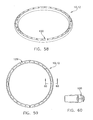
- FIG. 58 is a perspective view of yet a further alternative embodiment of O-ring
- FIG. 59 is a front elevational view of the O-ring shown in FIG. 58;
- FIG. 60 is a cross-sectional view, as taken along lines 60 - 60 in FIG. 59;
- FIG. 61 is a perspective view of yet a further alternative embodiment of O-ring
- FIG. 62 is a front elevational view of the O-ring shown in FIG. 61;
- FIG. 63 is a cross-sectional view, as taken along lines 63 - 63 in FIG. 62;
- FIG. 64 is a perspective view of yet a further alternative embodiment of O-ring
- FIG. 65 is a front elevational view of the O-ring shown in FIG. 64;
- FIG. 66 is a cross-sectional view, as taken along lines 66 - 66 in FIG. 65;
- FIG. 67 is a perspective view of yet a further alternative embodiment of O-ring
- FIG. 68 is a front elevational view of the O-ring shown in FIG. 67;
- FIG. 69 is a cross-sectional view, as taken along lines 69 - 69 in FIG. 68;
- FIG. 70 is a perspective view of an O-ring having a non-circular radial cross-section or stacked group of individual O-rings
- FIG. 71 is a front elevational view of the O-ring shown in FIG. 70;
- FIG. 72 is a cross-sectional view, as taken along lines 72 - 72 in FIG. 71;
- FIG. 73 is a perspective view of an O-ring having a non-circular radial cross-section or stacked group of individual hollow O-rings;
- FIG. 74 is a front elevational view of the O-ring shown in FIG. 73;
- FIG. 75 is a cross-sectional view, as taken along lines 75 - 75 in FIG. 74;
- FIG. 76 is a perspective view of an O-ring having a non-circular radial cross-section or stacked group of individual solid O-rings
- FIG. 77 is a front elevational view of the O-ring shown in FIG. 76;
- FIG. 78 is a cross-sectional view, as taken along lines 78 - 78 in FIG. 77;
- FIG. 79 is a perspective view of another O-ring having a non-circular radial cross-section or stacked group of individual hollow O-rings;
- FIG. 80 is a front elevational view of the O-ring shown in FIG. 79;
- FIG. 81 is a cross-sectional view, as taken along lines 81 - 81 in FIG. 80;
- FIG. 82 is a perspective view of yet another O-ring having a non-circular radial cross-section or stacked group of individual hollow O-rings;
- FIG. 83 is a front elevational view of the O-ring shown in FIG. 82;
- FIG. 84 is a cross-sectional view, as taken along lines 84 - 84 in FIG. 83;
- FIG. 85 is a perspective view of an O-ring having a non-circular radial cross-section or stacked group of individual solid O-rings;
- FIG. 86 is a front elevational view of the O-ring shown in FIG. 85;
- FIG. 87 is a cross-sectional view, as taken along lines 87 - 87 in FIG. 86;
- FIG. 88 is a perspective view of an O-ring having a stacked group of individual astroidal O-rings
- FIG. 89 is a front elevational view of the O-ring shown in FIG. 88;
- FIG. 90 is a cross-sectional view, as taken along lines 90 - 90 in FIG. 89;
- FIG. 91 is a perspective view of another O-ring having a stacked group of individual astroidal O-rings
- FIG. 92 is a front elevational view of the O-ring shown in FIG. 91;
- FIG. 93 is a cross-sectional view, as taken along lines 93 - 93 in FIG. 92;
- FIG. 94 is a perspective view of yet another O-ring having a stacked group of individual astroidal O-rings
- FIG. 95 is a front elevational view of the O-ring shown in FIG. 94;
- FIG. 96 is a cross-sectional view, as taken along lines 96 - 96 in FIG. 95;
- FIG. 97 is a perspective view of a further alternative O-ring having a stacked group of individual astroidal O-rings
- FIG. 98 is a front elevational view of the O-ring shown in FIG. 97;
- FIG. 99 is a cross-sectional view, as taken along lines 99 - 99 in FIG. 98;
- FIG. 100 is a perspective view of yet a further alternative O-ring having a stacked group of individual astroidal O-rings
- FIG. 101 is a front elevational view of the O-ring shown in FIG. 100;
- FIG. 102 is a cross-sectional view, as taken along lines 102 - 102 in FIG. 101;
- FIG. 103 is a perspective view of another further alternative O-ring having a stacked group of individual astroidal O-rings;
- FIG. 104 is a front elevational view of the O-ring shown in FIG. 103;
- FIG. 105 is a cross-sectional view, as taken along lines 105 - 105 in FIG. 104;
- FIG. 106 is a perspective view of a further alternative O-ring having a stacked group of individual astroidal O-rings
- FIG. 107 is a front elevational view of the O-ring shown in FIG. 106;
- FIG. 108 is a cross-sectional view, as taken along lines 108 - 108 in FIG. 107;
- FIG. 109 is a perspective view of another further alternative O-ring having a stacked group of individual astroidal O-rings
- FIG. 110 is a front elevational view of the O-ring shown in FIG. 109;
- FIG. 111 is a cross-sectional view, as taken along lines 111 - 111 in FIG. 110;
- FIGS. 112 - 115 are each a broken-away perspective view of alternative embodiments of astroidal cross-section O-rings formed in accordance with the present invention.
- FIG. 116 is a perspective view of an O-ring having an astroidal cross-section and a torsional preloading formed in accordance with another embodiment of the invention.
- FIG. 117 is a front elevational view of the preloaded O-ring shown in FIG. 116;
- FIG. 118 is a cross-sectional view, as taken along lines 118 - 118 in FIG. 117;
- FIG. 119 is a perspective, partially broken away view of an incrementally adjustable surgical wound protector comprising an O-ring having an astroidal cross-section and a torsional preloading formed in accordance with the present invention.
- an incrementally adjustable surgical wound protector 5 comprises a thin flexible sleeve 8 positioned between a first O-ring 10 and a second O-ring 12 .
- Sleeve 8 comprises a tube having a uniform circumference along its length, an upper end edge 16 , and a lower end edge 18 .
- Upper end edge 16 of sleeve 8 is fastened or bonded to a surface portion of first O-ring 10 by sealing, e.g., thermally, ultrasonically or, with proper pretreatment, adhesives, but without (i) the portion of sleeve 8 adjacent to upper end edge 16 being wrapped around the circumference of first O-ring 10 , or (ii) overlapped upon itself.
- lower end edge 18 of sleeve 8 is fastened or bonded to a surface portion of O-ring 12 by sealing, e.g., thermally, ultrasonically or, with proper pretreatment, adhesives, but without (i) the portion of sleeve 8 adjacent to lower end edge 18 being wrapped around the circumference of O-ring 12 , or (ii) overlapped upon itself (FIGS. 5 - 9 ).
- Sleeve 8 may also simply be attached to O-rings 10 , 12 by adhesive without pretreatment, but with less than satisfactory results.
- Sleeve 8 is preferably formed from a material that is impervious to solids and/or fluids containing bacteria and other harmful contaminants, e.g., a polymer or elastomeric material of the type known in the art.
- the materials and dimensions of wound protector 5 are selected to ensure stability of the wound protector when installed.
- a preferred polymer material suitable for sleeve 8 is a heat-sealable 2 -mil aromatic polyether polyurethane film, such as the PT6100 series manufactured by Deerfield Urethane, Inc., under the tradename DUROFLEX, that may be produced in seamless tubular form or by a flat sheet in a cylindrical form with the meeting margins along the side overlapped and sealed.
- a nominal sleeve length suitable for surgery is typically from about 100 to about 200 mm. Sleeve diameters will vary according to the length of the surgical incision.
- First O-ring 10 and second O-ring 12 each are formed so as to engage the inner edge of a surgical incision, with a portion of sleeve 8 above the incision and capable of being incrementally rolled toward the other O-ring to draw the remaining portion of sleeve 8 contiguous with the sides of the incision.
- O-rings 10 and 12 are preferably formed from an elastomeric medical grade material of sufficient hardness to retain O-rings 10 and 12 expanded in place around the inner and outer edges of the surgical incision. The material must be compliant enough to allow O-ring 10 or 12 to be turned by the fingers over 180 degrees about its center. For this purpose, urethane is a preferred elastomeric material.
- O-rings 10 , 12 may be formed from other resilient materials, such as medical grade, polyvinylchloride, silicon, natural rubber, or other elastomeric or rubber-like materials, with good effect.
- O-rings 10 , 12 preferably comprise a torus, i.e., a structure formed by the rotation of a polygon about an axis that lies in the plane of the polygon, but without cutting the polygon.
- O-rings 10 , 12 are formed from a solid or hollow, initially polygonal cross-section torus having a cross-sectional center 20 that is radially equidistant from a central longitudinal axis 24 of the O-ring.
- the polygonal cross-section of each O-ring 10 , 12 may be divided into four quadrants (FIGS. 3 , and 5 - 9 ). In one embodiment, material defining two diagonally opposed quadrants is removed, leaving two diagonally opposed recesses 26 and 28 (best shown in FIG. 3).
- first solid quadrant 30 includes a curved outer surface 36 , a curved annular surface 38 , and a sinusoidal surface 40 .
- Second solid quadrant 33 includes a curved outer surface 46 , a curved annular surface 48 , and a sinusoidal surface 50 .
- Curved annular surfaces 38 , 48 are at substantially the same radial distance from central longitudinal axis 24 , and are vertically oriented so as to be substantially parallel and substantially coaxial with central longitudinal axis 24 .
- Sinusoidal surfaces 40 , 50 extend transversely relative to the central longitudinal axis 24 of O-rings 10 , 12 (FIGS. 2 and 3).
- O-ring is not limited to solid, circular, or single ring structures or classic toroidal shapes, but also includes structures that are not circular, e.g., rectilinear, oval/elliptical, hexagonal, octagonal, non-circular radial, etc., or more than one torus stacked one upon the other, as long as such rings comprise a resilient configuration capable of being squeezed into an oblong shape that is suitable for insertion into a surgical incision.
- a urethane O-ring 10 , 12 for use with a sleeve having a diameter of about 109 mm has a diameter of about 7.9 mm, with a radial depth of diagonally opposed recesses 26 and 28 of approximately 4.0 mm.
- the sizes of the O-rings and sleeves will vary according to incision size and peritoneum wall thickness. The personal preference of the surgeon will also affect the choice of both O-ring and sleeve size for a particular surgical procedure.
- Each end of sleeve 8 is sealingly fastened or bonded around an O-ring 10 , 12 , e.g., to a curved outer surface 46 , such that when the sleeve is fully extended, O-rings 10 , 12 are positioned in spaced-apart relation to one another (FIGS. 1 and 5).
- the cross-sectional shape of O-rings 10 , 12 provides stability in a plane perpendicular to central longitudinal axis 24 , and provides an over-center “snap-action” or “snap-roll” when O-ring 10 , 12 is rolled about itself and sleeve 8 , thereby providing incremental shortening in predetermined increments and resistance to lengthening after shortening. More particularly, by strategically removing portions of O-rings 10 , 12 so as to form recesses 26 , 28 , the rate of twist necessary to create the over-center “snap-action” can be gauged and set.
- O-ring typically, about 33% to about 70% of the mass of the O-ring must be either removed or redistributed in order to obtain a “snap-action” that is suitable for hand twisting.
- numerous O-rings FIGS. 12 - 118 ), having differing amounts, locations, and shapes of material removed from their cross-section may be used in connection with the present invention.
- rings 10 , 12 may comprise a cruciform cross-sectional profile.
- the cruciform shape of O-rings 10 , 12 provide stability in a plane perpendicular to central longitudinal axis 24 and also provide the over-center, “snap-action” when rolled about themselves and sleeve 8 .
- the embodiment disclosed in FIGS. 10 - 12 includes a cruciform cross-section having flat surfaces 60 and 62 .
- FIGS. 13 - 15 show a similar O-ring 10 , 12 having radiused surfaces 65 and 67 .
- the end surfaces of the cruciform cross-section O-ring 10 , 12 may also have radiused end surfaces, as shown in FIGS. 12A and 15A.
- O-rings 10 , 12 may also include a plurality of recesses defined into a portion of the ring. More particularly, a plurality of recesses 70 are defined radially inwardly into O-ring 10 , 12 , i.e., toward cross-sectional center 20 , from diametrically opposed positions along the circumference of the O-ring. In this way, recesses 70 extend into O-ring 10 , 12 from each side in an alternating pattern.
- FIGS. 16 - 18 illustrate a rectilinearly shaped plurality of alternating recesses 70
- FIGS. 19 - 21 illustrate a plurality of round recesses 72
- FIGS. 22 - 24 illustrate a plurality of round, shallow recesses 72 a disposed on both sides of O-ring 10 , 12 .
- FIGS. 25 - 33 a sinusoidally defined recess 72 b may be employed with the present invention.
- FIGS. 25 - 27 illustrate such a sinusoidal recess 72 b disposed on an inner circumferential surface of O-ring 10 , 12
- FIGS. 28 - 30 illustrate such a sinusoidal recess 72 b disposed on an outer circumferential surface of O-ring 10 , 12
- FIGS. 31 - 33 illustrate a pair of sinusoidal recesses 72 b positioned in diametrically opposed relation to one another on O-ring 10 , 12 .
- the removal of material from O-ring 10 , 12 to define recesses 70 , 72 , or 72 b provides stability in a plane perpendicular to central longitudinal axis 24 , and provides an over-center “snap-action” when the O-ring is rolled about itself and sleeve 8 .
- O-rings 10 , 12 may also have a continuous recess formed in diametrically opposed portions of O-ring 10 , 12 . More particularly, a top recess 78 and a bottom recess 80 may be formed in O-ring 10 , 12 so as to yield “a bow-tie” cross-sectional profile to O-ring 10 , 12 (FIGS. 34 - 36 ) or may be formed so as to be shallow (FIGS. 37 - 39 ).
- the removal of material from O-ring 10 , 12 from diametrically opposed portions in a continuous, or annular fashion provides stability in a plane perpendicular to central longitudinal axis 24 , and provides an over-center “snap-action” when the O-ring is rolled about itself and sleeve 8 .
- a plurality of reinforcing ribs 82 may be formed within top recess 78 and/or bottom recess 80 so as to ease manufacture (FIGS. 40 - 42 ).
- O-rings 10 , 12 may also be formed so as to have convex top and bottom walls 86 , 88 , and substantially flat inner and outer, annular side walls 90 , 92 (FIGS. 43 - 45 ) or convex top and bottom walls 86 , 88 and convex inner and outer, annular side walls 94 , 96 (FIGS. 46 - 48 ).
- the reduction of material from O-ring 10 , 12 coupled with the curvature of either the top and bottom walls 86 , 88 or the annular inner and outer side walls 94 , 96 provides stability in a plane perpendicular to central longitudinal axis 24 , and provides an over-center “snap-action” when the O-ring is rolled about itself and sleeve 8 .
- O-ring 10 , 12 may also be formed so as to have nonparallel top and bottom walls 100 , 102 , and convex inner and outer, annular side walls 104 , 106 (FIGS. 49 - 51 ).
- O-ring 10 , 12 may also be formed so as to have nonparallel, convex top and bottom walls 108 , 110 , and convex inner and outer, annular side walls 112 , 114 (FIGS. 52 - 54 ).
- an additional annular flat 116 may be included at the transition between convex inner and outer, annular side walls 112 , 114 and convex top and bottom walls 108 , 110 (FIGS. 55 - 57 ).
- O-rings 10 , 12 may also include a plurality of through-holes 120 defined radially through O-ring 10 , 12 , i.e., through cross-sectional center 20 , from diametrically opposed positions along the circumference of the O-ring.
- FIGS. 58 - 63 illustrate a plurality of rectilinearly shaped through-holes 120 , and double through-holes 122 , respectively, while FIGS. 64 - 66 illustrate a plurality of round through-holes 124 .
- the removal of material from O-ring 10 , 12 to define through-holes 120 , 122 , or 124 provides stability in a plane perpendicular to central longitudinal axis 24 , and provides an over-center “snap-action” when the O-ring is rolled about itself and sleeve 8 .
- O-rings 10 , 12 may have additional material added to their circumference so as to form bulbous protrusions 128 over their outer surface, so as to redistribute the mass of the O-ring 10 , 12 .
- This redistribution of mass and concomitant change in the moment of inertia of O-ring 10 , 12 also provides stability in a plane perpendicular to central longitudinal axis 24 , and provides an over-center “snap-action” when the O-ring is rolled about itself and sleeve 8 .
- O-rings 10 , 12 may be formed from a plurality of individual O-rings 135 a , 135 b that are stacked one upon another so as to yield a stack of O-rings 136 that together comprise a non-circular radial cross-section.
- Individual O-rings 135 a , 135 b may comprise a solid or hollow, elliptical or circular cross-section (FIGS. 70 - 87 ) or a solid or hollow polygonal or astroidal cross-section (FIGS. 88 - 115 ).
- Hollow O-rings 135 a , 135 b may comprise one or more passageways 137 a , 137 b which may or may not be centrally located within each O-ring 135 a , 135 b .
- Stack of O-rings 136 provide annular, opposed curved surfaces 139 a , 139 b and unequal concentrations of material distributed about a centroid 140 that is defined by the point or area of engagement between one another.
- Sleeve 8 is fastened or bonded to a portion of either opposed curved surfaces 139 a , 139 b by sealing, e.g., thermally, ultrasonically, or adhesively, In this way, upon rolling or unrolling stacked O-rings 135 a , 135 b on sleeve 8 , using manual pressure on annular surfaces 139 a , 139 b , stacked O-rings 135 a , 135 b snap incrementally from one stable position to a next stable position.
- sealing e.g., thermally, ultrasonically, or adhesively
- stack of O-rings 136 may comprise multiple individual O-rings 135 a , 135 b , 135 c thus forming a non-circular radial cross-sectioned portions of stack 136 .
- Individual O-rings 135 a , 135 b , 135 c may also comprise a solid or hollow, elliptical or circular cross-section or a solid or hollow polygonal or astroidal cross-section (FIGS. 88 - 115 ).
- Hollow O-rings 135 a , 135 b , 135 c may comprise one or more passageways 137 a , 137 b , 137 c which may or may not be centrally located within each O-ring 135 a , 135 b , 135 c .
- Stack of O-rings 136 provide annular, opposed curved surfaces 139 a , 139 b , 139 c and unequal concentrations of material distributed about centroids 140 a , 140 b that are defined by the point or area of engagement between one another.
- O-rings 10 , 12 may also be formed with an astroidal or “star-shaped” cross-section, e.g. a cross-sectional shape comprising a hypercycloid having three or more cusps.
- An astroidal O-ring 10 , 12 may have any number of cusps 148 projecting radially outwardly relative to centroid 150 .
- an astroidal O-ring may have either a solid or hollow cross-section, a solid cross-section is often preferred.
- Cusps 148 may be somewhat rounded or pointed at their apex, and may or may not be symmetrically arranged about a centroid 152 of the O-ring.
- O-rings 10 , 12 may comprise individual astroidal rings, or may be formed from a plurality of individual astroidal O-rings 155 a , 155 b , 155 c that are stacked one upon another so as to yield a stack of O-rings 156 that together comprise a non-circular radial cross-section (FIGS. 88 - 111 ).
- an astroidal O-ring 10 , 12 may comprise a torsional preloading that enhances its ability to snap incrementally from one stable position to a next stable position.
- a continuous length of astroidal cross-section, relatively resilient material is extruded in a conventional manner.
- a discrete length of the extruded material is cut and then twisted such that cusps 148 are rotated relative to centroid 150 by as much as 45° to 90° so as to store torsional energy within the extruded material.
- the free ends of the discrete length of extruded material are arranged so as to be adjacent to one another, and then bonded to one another either thermally of ultrasonically so as to form a ring. In this way, the torsional preload is maintained within the thus formed O-ring 10 , 12 .
- Astroidal O-rings 10 , 12 may be formed into an incrementally adjustable surgical wound protector 5 by fastening or otherwise bonding lower end edge 18 of sleeve 8 to a surface portion of O-ring 12 either between cusps 148 , or directly to cusps 148 , by sealing, e.g., thermally, ultrasonically or adhesives, but without the portion of sleeve 8 adjacent to lower end edge 18 being wrapped around the circumference of O-ring 12 , or overlapped upon itself (FIG. 119).
- the torsional preloading enhances the snap-action rolling of astroidal O-ring 12 by providing a predisposition within the ring to roll in a preferred manner.
- adjustable surgical wound protector 5 when adjustable surgical wound protector 5 is to be used in an abdominal surgical procedure, the abdomen 55 is routinely prepared with antiseptics; the site for the incision is traced on abdomen 55 and covered with a surgical drape; and a muscle-split is made at the site through the peritoneum.
- One O-ring (identified by reference numeral 12 in FIGS. 6 - 9 ) is squeezed lengthwise and inserted into the surgical incision and through the peritoneum, where it is released and returns to its original circular shape. In this position, O-ring 12 is placed within the body cavity and O-ring 10 is positioned outside of the body cavity, with sleeve 8 extending through the body cavity.
- O-rings 10 , 12 are completely interchangeable. Outer O-ring 10 is then gripped by the thumb and fingers and turned outwardly, in opposite directions, so as to roll sleeve 8 incrementally, i.e., so as to create repeated over-center “snap-rolls” of the O-ring. As a consequence, sleeve 8 is reeled onto outer O-ring 10 until outer O-ring 10 abuts the outer surface of abdomen 55 . The portion of sleeve 8 that is in the incision, and between O-rings 10 , 12 is drawn into contiguous contact with the sides of the incision so as to provide a self-retaining protective barrier during surgery which is impervious to contaminating solids and fluids.
- the present invention provides a relatively low cost surgical wound protector of simplified and selectively adjustable design which can be easily installed in a wound and adjusted in place to form fit a wide range of cavity wall thicknesses for protection against harmful contaminants.
- Another advantage of the invention is the provision of an adjustable wound protector in which relatively few sizes are needed to form fit a wide range of incision sizes and cavity wall thicknesses.
- Still another advantage of the invention is the provision of a surgical wound protector which can be adjusted after being inserted in a wound to obtain contiguous contact with the sides of the cavity wall.
- a still further advantage of the invention is the provision of a single, easily manufactured O-ring design that provides for a “snap-action” when rolled in itself so as to reel a sleeve onto the O-ring after being inserted in an incision for securing the sleeve in contiguous contact with the sides of the incision.
Abstract
Description
- This application is a continuation-in-part of application Ser. No. 10/196,647, filed Jul. 16, 2002, which is itself a continuation of application Ser. No. 09/970,416, filed Oct. 3, 2001, and now issued as U.S. Pat. No. 6,450,983.
- The present invention relates generally to surgical wound protectors, and more particularly to an adjustable surgical wound protector for use in protecting incised cavity walls of various thicknesses from harmful contaminants during surgery.
- The sides of a wound during surgery are inherently susceptible to bacterial infection if touched by contaminated substances such as diseased body parts and fluids as they pass through the wound. Therefore extreme care must be exercised to insure that the exposed sides of an incision are completely covered by a material impervious to solids and fluids containing bacteria and other contaminants before surgery proceeds.
- Various techniques have been used to insulate any incised tissue from exposure. One form of protection for relatively large incisions typically employs soft cotton sponges held against the sides of the wound by metal retractors to minimize contamination as well as to give the surgeon better access into the operating site. Another form of wound protector, particularly suitable for surgery, is disclosed in U.S. Pat. No. 3,347,227 to Harrower. Harrower discloses a surgical incision protector consisting of a pair of flexible rings joined by a thin, tubular-shaped sheet of flexible material. Harrower's rings have sufficient preforming to give a generally oval shape, be resilient and flexible, and so as to be easily flexed for insertion through a wound opening. The thin sheet is preferably made of plastic and must be impermeable to fluids and bacteria, physiologically inert, unaffected by autoclaving or sterilization, free of electrostatic hazard, resistant to melting, non-flammable, and somewhat elastic. Each of Harrower's flexible rings has a substantially circular cross-section. Harrower's incision protector is assembled by securing each end of the tubular sheet of flexible material to a ring, so that each ring is positioned at an end of the thin sheet of tubular material. In use, one ring is squeezed into an oblong shape, inserted through the peritoneum, and allowed to expand to the preformed shape over the inside edge of the wound. The other ring overlaps the outside edge causing the sleeve to stretch into contiguous contact with the entire surface of the sides and inner and outer edges of the wound. To obtain a form-fitting contiguous contact with the sides of the wound, the circumference of both rings in their preformed shape are slightly larger than that of the incision, and the extended length of the sleeve between the rings is slightly greater than that of the wall thickness. To accommodate variations in wound size, Harrower's wound protectors are manufactured in numerous combinations and permutations of both circumference and length.
- U.S. Pat. No. 3,347,226 to Harrower describes an adjustable wound protector which reduces, to a degree, the number of sizes required. It requires a number of predetermined lengths similar to U.S. Pat. No. 3,347,227, except the circumference of the wound protector is adjustable, before being installed in the wound, by the rings having telescoping ends, and the side of the sleeve having overlapping lengthwise edges. Any overlapping excess may be cut off. The rings have a maximum adjustable circumference slightly larger than that of the largest incision anticipated so that they are sure to overlap the inner and outer edges of the wound. However, a sleeve length must be selected which will closely conform to the wall thickness at the wound.
- U.S. Pat. No. 5,524,644, issued to Crook discloses an incrementally adjustable apparatus for protecting an incised wound from exposure to bacterial and other harmful contaminants. Crook provides a pair of resilient O-rings that are connected to opposite ends of an impermeable pliable sleeve. One of the O-rings is formed to engage the inner edge of the wound with a portion of the sleeve which is capable of being rolled onto the other ring to draw the remaining sleeve portion contiguous with the sides of the wound. Significantly, Crook relies upon flat surfaces on the rolled ring, that form an oblate cross-section, to provide a gripping surface to turn the ring about its annular axis.
- The present invention provides an O-ring for use in an adjustable surgical wound protector of the type having an impermeable tubular sleeve extending between O-rings. The O-ring comprises a non-circular radial cross-section with opposed surfaces so as to enable a snap-action rolling of the O-ring in predetermined increments. In this way, a portion of the tubular sleeve may be rolled upon itself about the O-ring to shorten the sleeve in predetermined increments and to resist subsequent lengthening. The non-circular radial cross-section may have more than one centroid disposed between opposed surfaces. In one embodiment, a stacked arrangement of two, three, or more individual O-rings are provided where a centroid is disposed between adjacent stacked O-rings.
- In an alternative embodiment, an O-ring is provided for use in an adjustable surgical wound protector of the type having an impermeable tubular sleeve extending between O-rings. The O-ring comprises an astroidal cross-section having a centroid and a torsional preloading so as to enable a snap-action rolling of the O-ring in predetermined increments for rolling a portion of the tubular sleeve on itself about the O-ring to shorten the sleeve in predetermined increments and to resist subsequent lengthening.
- An adjustable surgical wound protector is also provided that comprises an elongate open-ended tube formed of a pliable material that is impervious to solid and fluid contaminants for inserting lengthwise into a surgical incision. Two O-rings are provided, one each secured around the open ends of the tube, and having a resilient configuration for overlapping the inner edge of the wound and for squeezing into an oblong shape that is insertable with a lengthwise portion of the sleeve adjacent to one of the O-rings in the surgical incision. At least one O-ring comprises a non-circular radial cross-section with opposed surfaces so as to enable a snap-action rolling of the O-ring in predetermined increments for rolling a portion of the tubular sleeve on itself about the O-ring to shorten the tube in predetermined increments and to resist subsequent lengthening. In one embodiment, a stacked arrangement of two, three, or more individual O-rings are provided as the at least one O-ring, where a centroid is disposed between adjacent stacked O-rings.
- In an alternative embodiment, an adjustable surgical wound protector is provided including an elongate open-ended tube formed of a pliable material that is impervious to solid and fluid contaminants, and that can be inserted lengthwise into a surgical incision. Two O-rings are also provided, one each secured around the open ends of the tube. The O-rings have a resilient configuration for overlapping the inner edge of the wound and for squeezing into an oblong shape that is insertable with a lengthwise portion of the sleeve adjacent to one of the O-rings in the surgical incision. At least one O-ring comprises an astroidal cross-section having a centroid and a torsional preloading so as to enable a snap-action rolling of the O-ring in predetermined increments for rolling a portion of the tubular sleeve on itself about the O-ring to shorten the sleeve in predetermined increments and to resist subsequent lengthening.
- These and other features and advantages of the present invention will be more fully disclosed in, or rendered obvious by, the following detailed description of the preferred embodiment of the invention, which is to be considered together with the accompanying drawings wherein like numbers refer to like parts and further wherein:
- FIG. 1 is a perspective, partially broken away view of an incrementally adjustable surgical wound protector formed in accordance with the present invention;
- FIG. 2 is a perspective view of an O-ring formed in accordance with a preferred embodiment of the present invention;
- FIG. 3 is a cross-sectional view of the O-ring shown in FIG. 2, as taken along lines 3-3 in FIG. 2, and including a portion of the interior side surface of the O-ring;
- FIG. 4 is a side-elevational view of the O-ring shown in FIG. 2;
- FIG. 5 is a broken away, cross-sectional view of the incrementally adjustable surgical wound protector shown in FIG. 1, as taken along lines 5-5 in FIG. 1, illustrating the interconnection between the O-ring and sleeve;
- FIGS. 6-9 illustrate in sequence, the operation of the incrementally adjustable surgical wound protector shown in FIG. 1;
- FIG. 10 is a perspective view of one alternative embodiment of O-ring;
- FIG. 11 is a side elevational view of the O-ring shown in FIG. 10;
- FIG. 12 is a cross-sectional view, taken along line 12-12 in FIG. 11;
- FIG. 12A is a cross-sectional view similar to that shown in FIG. 12, but illustrating an alternative cruciform cross-section having radiused end surfaces;
- FIG. 13 is a perspective view of another embodiment of O-ring;
- FIG. 14 is a side elevational view of the O-ring shown in FIG. 13;
- FIG. 15 is a cross-sectional view, as taken along lines 15-15 in FIG. 14, showing an alternative cruciform cross-section;
- FIG. 15A is a cross-sectional view similar to that shown in FIG. 15, but illustrating an alternative cruciform cross-section having radiused end surfaces;
- FIG. 16 is a perspective view of yet another alternative embodiment of O-ring;
- FIG. 17 is a side elevational view of the O-ring shown in FIG. 16;
- FIG. 18 is a cross-sectional view, as taken along line 18-18 in FIG. 17, showing an embodiment of recess used in connection with the present invention;
- FIG. 19 is a perspective view of a further alternative embodiment of O-ring;
- FIG. 20 is a side elevational view of the O-ring shown in FIG. 19;
- FIG. 21 is a cross-sectional view, as taken along the line 21-21 in FIG. 20;
- FIG. 22 is a perspective view of yet a further alternative embodiment of O-ring;
- FIG. 23 is a front elevational view of the O-ring shown in FIG. 22;
- FIG. 24 is a cross-sectional view, as taken along lines 24-24 in FIG. 23;
- FIG. 25 is a perspective view of yet a further alternative embodiment of O-ring;
- FIG. 26 is a front elevational view of the O-ring shown in FIG. 25;
- FIG. 27 is a cross-sectional view, as taken along lines 27-27 in FIG. 26;
- FIG. 28 is a perspective view of yet a further alternative embodiment of O-ring;
- FIG. 29 is a front elevational view of the O-ring shown in FIG. 28;
- FIG. 30 is a cross-sectional view, as taken along lines 30-30 in FIG. 29;
- FIG. 31 is a perspective view of yet a further alternative embodiment of O-ring;
- FIG. 32 is a front elevational view of the O-ring shown in FIG. 31;
- FIG. 33 is a cross-sectional view, as taken along lines 33-33 in FIG. 32
- FIG. 34 is a perspective view of yet a further alternative embodiment of O-ring;
- FIG. 35 is a front elevational view of the O-ring shown in FIG. 34;
- FIG. 36 is a cross-sectional view, as taken along lines 36-36 in FIG. 35;
- FIG. 37 is a perspective view of yet a further alternative embodiment of O-ring;
- FIG. 38 is a front elevational view of the O-ring shown in FIG. 37;
- FIG. 39 is a cross-sectional view, as taken along lines 39-39 in FIG. 38;
- FIG. 40 is a perspective view of yet a further alternative embodiment of O-ring;
- FIG. 41 is a front elevational view of the O-ring shown in FIG. 40;
- FIG. 42 is a cross-sectional view, as taken along lines 42-42 in FIG. 41;
- FIG. 43 is a perspective view of yet a further alternative embodiment of O-ring;
- FIG. 44 is a front elevational view of the O-ring shown in FIG. 43;
- FIG. 45 is a cross-sectional view, as taken along lines 45-45 in FIG. 44;
- FIG. 46 is a perspective view of yet a further alternative embodiment of O-ring;
- FIG. 47 is a front elevational view of the O-ring shown in FIG. 46;
- FIG. 48 is a cross-sectional view, as taken along lines 48-48 in FIG. 47;
- FIG. 49 is a perspective view of yet a further alternative embodiment of O-ring;
- FIG. 50 is a front elevational view of the O-ring shown in FIG. 49;
- FIG. 51 is a cross-sectional view, as taken along lines 51-51 in FIG. 50;
- FIG. 52 is a perspective view of yet a further alternative embodiment of O-ring;
- FIG. 53 is a front elevational view of the O-ring shown in FIG. 52;
- FIG. 54 is a cross-sectional view, as taken along lines 54-54 in FIG. 53;
- FIG. 55 is a perspective view of yet a further alternative embodiment of O-ring;
- FIG. 56 is a front elevational view of the O-ring shown in FIG. 55;
- FIG. 57 is a cross-sectional view, as taken along lines 57-57 in FIG. 56;
- FIG. 58 is a perspective view of yet a further alternative embodiment of O-ring;
- FIG. 59 is a front elevational view of the O-ring shown in FIG. 58;
- FIG. 60 is a cross-sectional view, as taken along lines 60-60 in FIG. 59;
- FIG. 61 is a perspective view of yet a further alternative embodiment of O-ring;
- FIG. 62 is a front elevational view of the O-ring shown in FIG. 61;
- FIG. 63 is a cross-sectional view, as taken along lines 63-63 in FIG. 62;
- FIG. 64 is a perspective view of yet a further alternative embodiment of O-ring;
- FIG. 65 is a front elevational view of the O-ring shown in FIG. 64;
- FIG. 66 is a cross-sectional view, as taken along lines 66-66 in FIG. 65;
- FIG. 67 is a perspective view of yet a further alternative embodiment of O-ring;
- FIG. 68 is a front elevational view of the O-ring shown in FIG. 67;
- FIG. 69 is a cross-sectional view, as taken along lines 69-69 in FIG. 68;
- FIG. 70 is a perspective view of an O-ring having a non-circular radial cross-section or stacked group of individual O-rings;
- FIG. 71 is a front elevational view of the O-ring shown in FIG. 70;
- FIG. 72 is a cross-sectional view, as taken along lines 72-72 in FIG. 71;
- FIG. 73 is a perspective view of an O-ring having a non-circular radial cross-section or stacked group of individual hollow O-rings;
- FIG. 74 is a front elevational view of the O-ring shown in FIG. 73;
- FIG. 75 is a cross-sectional view, as taken along lines 75-75 in FIG. 74;
- FIG. 76 is a perspective view of an O-ring having a non-circular radial cross-section or stacked group of individual solid O-rings;
- FIG. 77 is a front elevational view of the O-ring shown in FIG. 76;
- FIG. 78 is a cross-sectional view, as taken along lines 78-78 in FIG. 77;
- FIG. 79 is a perspective view of another O-ring having a non-circular radial cross-section or stacked group of individual hollow O-rings;
- FIG. 80 is a front elevational view of the O-ring shown in FIG. 79;
- FIG. 81 is a cross-sectional view, as taken along lines 81-81 in FIG. 80;
- FIG. 82 is a perspective view of yet another O-ring having a non-circular radial cross-section or stacked group of individual hollow O-rings;
- FIG. 83 is a front elevational view of the O-ring shown in FIG. 82;
- FIG. 84 is a cross-sectional view, as taken along lines 84-84 in FIG. 83;
- FIG. 85 is a perspective view of an O-ring having a non-circular radial cross-section or stacked group of individual solid O-rings;
- FIG. 86 is a front elevational view of the O-ring shown in FIG. 85;
- FIG. 87 is a cross-sectional view, as taken along lines 87-87 in FIG. 86;
- FIG. 88 is a perspective view of an O-ring having a stacked group of individual astroidal O-rings;
- FIG. 89 is a front elevational view of the O-ring shown in FIG. 88;
- FIG. 90 is a cross-sectional view, as taken along lines 90-90 in FIG. 89;
- FIG. 91 is a perspective view of another O-ring having a stacked group of individual astroidal O-rings;
- FIG. 92 is a front elevational view of the O-ring shown in FIG. 91;
- FIG. 93 is a cross-sectional view, as taken along lines 93-93 in FIG. 92;
- FIG. 94 is a perspective view of yet another O-ring having a stacked group of individual astroidal O-rings;
- FIG. 95 is a front elevational view of the O-ring shown in FIG. 94;
- FIG. 96 is a cross-sectional view, as taken along lines 96-96 in FIG. 95;
- FIG. 97 is a perspective view of a further alternative O-ring having a stacked group of individual astroidal O-rings;
- FIG. 98 is a front elevational view of the O-ring shown in FIG. 97;
- FIG. 99 is a cross-sectional view, as taken along lines 99-99 in FIG. 98;
- FIG. 100 is a perspective view of yet a further alternative O-ring having a stacked group of individual astroidal O-rings;
- FIG. 101 is a front elevational view of the O-ring shown in FIG. 100;
- FIG. 102 is a cross-sectional view, as taken along lines 102-102 in FIG. 101;
- FIG. 103 is a perspective view of another further alternative O-ring having a stacked group of individual astroidal O-rings;
- FIG. 104 is a front elevational view of the O-ring shown in FIG. 103;
- FIG. 105 is a cross-sectional view, as taken along lines 105-105 in FIG. 104;
- FIG. 106 is a perspective view of a further alternative O-ring having a stacked group of individual astroidal O-rings;
- FIG. 107 is a front elevational view of the O-ring shown in FIG. 106;
- FIG. 108 is a cross-sectional view, as taken along lines 108-108 in FIG. 107;
- FIG. 109 is a perspective view of another further alternative O-ring having a stacked group of individual astroidal O-rings;
- FIG. 110 is a front elevational view of the O-ring shown in FIG. 109;
- FIG. 111 is a cross-sectional view, as taken along lines 111-111 in FIG. 110;
- FIGS. 112-115 are each a broken-away perspective view of alternative embodiments of astroidal cross-section O-rings formed in accordance with the present invention;
- FIG. 116 is a perspective view of an O-ring having an astroidal cross-section and a torsional preloading formed in accordance with another embodiment of the invention;
- FIG. 117 is a front elevational view of the preloaded O-ring shown in FIG. 116;
- FIG. 118 is a cross-sectional view, as taken along lines 118-118 in FIG. 117; and
- FIG. 119 is a perspective, partially broken away view of an incrementally adjustable surgical wound protector comprising an O-ring having an astroidal cross-section and a torsional preloading formed in accordance with the present invention.
- This description of preferred embodiments is intended to be read in connection with the accompanying drawings, which are to be considered part of the entire written description of this invention. In the description, relative terms such as “horizontal,” “vertical,” “up,” “down,” “top” and “bottom” as well as derivatives thereof (e.g., “horizontally,” “downwardly,” “upwardly,” etc.) should be construed to refer to the orientation as then described or as shown in the drawing figure under discussion. These relative terms are for convenience of description and normally are not intended to require a particular orientation. Terms including “inwardly” versus “outwardly,” “longitudinal” versus “lateral” and the like are to be interpreted relative to one another or relative to an axis of elongation, or an axis or center of rotation, as appropriate. Terms concerning attachments, coupling and the like, such as “connected” and “interconnected,” refer to a relationship wherein structures are secured or attached to one another either directly or indirectly through intervening structures, as well as both movable or rigid attachments or relationships, unless expressly described otherwise. The term “operatively connected” is such an attachment, coupling or connection that allows the pertinent structures to operate as intended by virtue of that relationship. In the claims, means-plus-function clauses are intended to cover the structures described herein as performing the recited function, including not only structural equivalents but also equivalent structures.
- Referring to FIG. 1, an incrementally adjustable
surgical wound protector 5 comprises a thinflexible sleeve 8 positioned between a first O-ring 10 and a second O-ring 12.Sleeve 8 comprises a tube having a uniform circumference along its length, anupper end edge 16, and alower end edge 18.Upper end edge 16 ofsleeve 8 is fastened or bonded to a surface portion of first O-ring 10 by sealing, e.g., thermally, ultrasonically or, with proper pretreatment, adhesives, but without (i) the portion ofsleeve 8 adjacent toupper end edge 16 being wrapped around the circumference of first O-ring 10, or (ii) overlapped upon itself. Likewise,lower end edge 18 ofsleeve 8 is fastened or bonded to a surface portion of O-ring 12 by sealing, e.g., thermally, ultrasonically or, with proper pretreatment, adhesives, but without (i) the portion ofsleeve 8 adjacent tolower end edge 18 being wrapped around the circumference of O-ring 12, or (ii) overlapped upon itself (FIGS. 5-9).Sleeve 8 may also simply be attached to O-rings -
Sleeve 8 is preferably formed from a material that is impervious to solids and/or fluids containing bacteria and other harmful contaminants, e.g., a polymer or elastomeric material of the type known in the art. The materials and dimensions ofwound protector 5 are selected to ensure stability of the wound protector when installed. A preferred polymer material suitable forsleeve 8 is a heat-sealable 2-mil aromatic polyether polyurethane film, such as the PT6100 series manufactured by Deerfield Urethane, Inc., under the tradename DUROFLEX, that may be produced in seamless tubular form or by a flat sheet in a cylindrical form with the meeting margins along the side overlapped and sealed. Other materials that may be used with good effect include, polyolefins and other like plastomers and elastomers that are suitable for use in medical applications. A nominal sleeve length suitable for surgery is typically from about 100 to about 200 mm. Sleeve diameters will vary according to the length of the surgical incision. - First O-
ring 10 and second O-ring 12 each are formed so as to engage the inner edge of a surgical incision, with a portion ofsleeve 8 above the incision and capable of being incrementally rolled toward the other O-ring to draw the remaining portion ofsleeve 8 contiguous with the sides of the incision. O-rings rings ring rings - Referring to FIGS. 1-5, O-
rings rings cross-sectional center 20 that is radially equidistant from a centrallongitudinal axis 24 of the O-ring. The polygonal cross-section of each O-ring recesses 26 and 28 (best shown in FIG. 3). - In this embodiment, the solid portion of O-
rings solid quadrant 30 and a diagonally opposed, secondsolid quadrant 33. Firstsolid quadrant 30 includes a curvedouter surface 36, a curvedannular surface 38, and asinusoidal surface 40. Secondsolid quadrant 33 includes a curvedouter surface 46, a curvedannular surface 48, and asinusoidal surface 50. Curvedannular surfaces longitudinal axis 24, and are vertically oriented so as to be substantially parallel and substantially coaxial with centrallongitudinal axis 24. Sinusoidal surfaces 40,50 extend transversely relative to the centrallongitudinal axis 24 of O-rings 10,12 (FIGS. 2 and 3). - Of course, it will be understood that the term “O-ring” is not limited to solid, circular, or single ring structures or classic toroidal shapes, but also includes structures that are not circular, e.g., rectilinear, oval/elliptical, hexagonal, octagonal, non-circular radial, etc., or more than one torus stacked one upon the other, as long as such rings comprise a resilient configuration capable of being squeezed into an oblong shape that is suitable for insertion into a surgical incision.
- By way of example, a urethane O-
ring recesses sleeve 8 is sealingly fastened or bonded around an O-ring outer surface 46, such that when the sleeve is fully extended, O-rings - The cross-sectional shape of O-
rings longitudinal axis 24, and provides an over-center “snap-action” or “snap-roll” when O-ring sleeve 8, thereby providing incremental shortening in predetermined increments and resistance to lengthening after shortening. More particularly, by strategically removing portions of O-rings - For example, and referring to FIGS. 10-15, rings 10,12 may comprise a cruciform cross-sectional profile. In this configuration, the cruciform shape of O-
rings longitudinal axis 24 and also provide the over-center, “snap-action” when rolled about themselves andsleeve 8. The embodiment disclosed in FIGS. 10-12 includes a cruciform cross-section havingflat surfaces ring surfaces ring - Referring to FIGS. 16-33, O-
rings recesses 70 are defined radially inwardly into O-ring cross-sectional center 20, from diametrically opposed positions along the circumference of the O-ring. In this way, recesses 70 extend into O-ring recesses 70, while FIGS. 19-21 illustrate a plurality ofround recesses 72 and FIGS. 22-24 illustrate a plurality of round,shallow recesses 72 a disposed on both sides of O-ring - Referring to FIGS. 25-33, a sinusoidally defined
recess 72 b may be employed with the present invention. FIGS. 25-27 illustrate such asinusoidal recess 72 b disposed on an inner circumferential surface of O-ring sinusoidal recess 72 b disposed on an outer circumferential surface of O-ring sinusoidal recesses 72 b positioned in diametrically opposed relation to one another on O-ring ring recesses longitudinal axis 24, and provides an over-center “snap-action” when the O-ring is rolled about itself andsleeve 8. - Referring to FIGS. 34-42, O-
rings ring top recess 78 and abottom recess 80 may be formed in O-ring ring 10,12 (FIGS. 34-36) or may be formed so as to be shallow (FIGS. 37-39). The removal of material from O-ring longitudinal axis 24, and provides an over-center “snap-action” when the O-ring is rolled about itself andsleeve 8. A plurality of reinforcingribs 82 may be formed withintop recess 78 and/orbottom recess 80 so as to ease manufacture (FIGS. 40-42). - Referring to FIGS. 43-57, O-
rings bottom walls annular side walls 90,92 (FIGS. 43-45) or convex top andbottom walls annular side walls 94,96 (FIGS. 46-48). The reduction of material from O-ring bottom walls outer side walls longitudinal axis 24, and provides an over-center “snap-action” when the O-ring is rolled about itself andsleeve 8. - Additionally, O-
ring bottom walls annular side walls 104,106 (FIGS. 49-51). Alternatively, O-ring bottom walls annular side walls 112,114 (FIGS. 52-54). Also, an additional annular flat 116 may be included at the transition between convex inner and outer,annular side walls bottom walls 108,110 (FIGS. 55-57). - Referring to FIGS. 58-66, O-
rings holes 120 defined radially through O-ring cross-sectional center 20, from diametrically opposed positions along the circumference of the O-ring. FIGS. 58-63 illustrate a plurality of rectilinearly shaped through-holes 120, and double through-holes 122, respectively, while FIGS. 64-66 illustrate a plurality of round through-holes 124. In each case, the removal of material from O-ring holes longitudinal axis 24, and provides an over-center “snap-action” when the O-ring is rolled about itself andsleeve 8. - Referring to FIGS. 67-69, in some instances, O-
rings bulbous protrusions 128 over their outer surface, so as to redistribute the mass of the O-ring ring longitudinal axis 24, and provides an over-center “snap-action” when the O-ring is rolled about itself andsleeve 8. - Referring to FIGS. 70-78, O-
rings rings rings 136 that together comprise a non-circular radial cross-section. Individual O-rings rings more passageways ring rings 136 provide annular, opposedcurved surfaces centroid 140 that is defined by the point or area of engagement between one another.Sleeve 8 is fastened or bonded to a portion of either opposedcurved surfaces rings sleeve 8, using manual pressure onannular surfaces rings - Referring to FIGS. 79-87, stack of O-
rings 136 may comprise multiple individual O-rings stack 136. Individual O-rings rings more passageways ring rings 136 provide annular, opposedcurved surfaces centroids - Referring to FIGS. 88-118, O-
rings ring cusps 148 projecting radially outwardly relative tocentroid 150. Although an astroidal O-ring may have either a solid or hollow cross-section, a solid cross-section is often preferred.Cusps 148 may be somewhat rounded or pointed at their apex, and may or may not be symmetrically arranged about acentroid 152 of the O-ring. O-rings rings - In another embodiment, an astroidal O-
ring cusps 148 are rotated relative tocentroid 150 by as much as 45° to 90° so as to store torsional energy within the extruded material. Once in this position, the free ends of the discrete length of extruded material are arranged so as to be adjacent to one another, and then bonded to one another either thermally of ultrasonically so as to form a ring. In this way, the torsional preload is maintained within the thus formed O-ring - Astroidal O-
rings surgical wound protector 5 by fastening or otherwise bondinglower end edge 18 ofsleeve 8 to a surface portion of O-ring 12 either betweencusps 148, or directly tocusps 148, by sealing, e.g., thermally, ultrasonically or adhesives, but without the portion ofsleeve 8 adjacent tolower end edge 18 being wrapped around the circumference of O-ring 12, or overlapped upon itself (FIG. 119). The torsional preloading enhances the snap-action rolling of astroidal O-ring 12 by providing a predisposition within the ring to roll in a preferred manner. - Referring again to FIGS. 6-9, when adjustable
surgical wound protector 5 is to be used in an abdominal surgical procedure, the abdomen 55 is routinely prepared with antiseptics; the site for the incision is traced onabdomen 55 and covered with a surgical drape; and a muscle-split is made at the site through the peritoneum. One O-ring (identified byreference numeral 12 in FIGS. 6-9) is squeezed lengthwise and inserted into the surgical incision and through the peritoneum, where it is released and returns to its original circular shape. In this position, O-ring 12 is placed within the body cavity and O-ring 10 is positioned outside of the body cavity, withsleeve 8 extending through the body cavity. It will be understood that O-rings ring 10 is then gripped by the thumb and fingers and turned outwardly, in opposite directions, so as to rollsleeve 8 incrementally, i.e., so as to create repeated over-center “snap-rolls” of the O-ring. As a consequence,sleeve 8 is reeled onto outer O-ring 10 until outer O-ring 10 abuts the outer surface ofabdomen 55. The portion ofsleeve 8 that is in the incision, and between O-rings - Advantages of the Invention
- Numerous advantages are obtained by employing the present invention.
- The present invention provides a relatively low cost surgical wound protector of simplified and selectively adjustable design which can be easily installed in a wound and adjusted in place to form fit a wide range of cavity wall thicknesses for protection against harmful contaminants.
- Another advantage of the invention is the provision of an adjustable wound protector in which relatively few sizes are needed to form fit a wide range of incision sizes and cavity wall thicknesses.
- Still another advantage of the invention is the provision of a surgical wound protector which can be adjusted after being inserted in a wound to obtain contiguous contact with the sides of the cavity wall.
- A still further advantage of the invention is the provision of a single, easily manufactured O-ring design that provides for a “snap-action” when rolled in itself so as to reel a sleeve onto the O-ring after being inserted in an incision for securing the sleeve in contiguous contact with the sides of the incision.
- It is to be understood that the present invention is by no means limited only to the particular constructions herein disclosed and shown in the drawings, but also comprises any modifications or equivalents within the scope of the claims.
Claims (37)
Priority Applications (3)
| Application Number | Priority Date | Filing Date | Title |
|---|---|---|---|
| US10/440,757 US20030192553A1 (en) | 2001-10-03 | 2003-05-19 | O-ring for incrementally adjustable incision liner and retractor |
| EP04752598A EP1638441A2 (en) | 2003-05-19 | 2004-05-19 | Improved o-ring for incrementally adjustable incision liner and retractor |
| PCT/US2004/015604 WO2004103161A2 (en) | 2001-10-03 | 2004-05-19 | Improved o-ring for incrementally adjustable incision liner and retractor |
Applications Claiming Priority (3)
| Application Number | Priority Date | Filing Date | Title |
|---|---|---|---|
| US09/970,416 US6450983B1 (en) | 2001-10-03 | 2001-10-03 | O-ring for incrementally adjustable incision liner and retractor |
| US10/196,647 US6613952B2 (en) | 2001-10-03 | 2002-07-16 | O-ring for incrementally adjustable incision liner and retractor |
| US10/440,757 US20030192553A1 (en) | 2001-10-03 | 2003-05-19 | O-ring for incrementally adjustable incision liner and retractor |
Related Parent Applications (1)
| Application Number | Title | Priority Date | Filing Date |
|---|---|---|---|
| US10/196,647 Continuation-In-Part US6613952B2 (en) | 2001-10-03 | 2002-07-16 | O-ring for incrementally adjustable incision liner and retractor |
Publications (1)
| Publication Number | Publication Date |
|---|---|
| US20030192553A1 true US20030192553A1 (en) | 2003-10-16 |
Family
ID=36337563
Family Applications (1)
| Application Number | Title | Priority Date | Filing Date |
|---|---|---|---|
| US10/440,757 Abandoned US20030192553A1 (en) | 2001-10-03 | 2003-05-19 | O-ring for incrementally adjustable incision liner and retractor |
Country Status (1)
| Country | Link |
|---|---|
| US (1) | US20030192553A1 (en) |
Cited By (60)
| Publication number | Priority date | Publication date | Assignee | Title |
|---|---|---|---|---|
| US20040015185A1 (en) * | 2000-10-19 | 2004-01-22 | Ewers Richard C. | Surgical access apparatus and method |
| US20050288558A1 (en) * | 2001-10-20 | 2005-12-29 | Applied Medical Resources Corporation | Wound retraction apparatus and method |
| US20080011307A1 (en) * | 2006-07-12 | 2008-01-17 | Beckman Andrew T | Hand assisted laparoscopic device |
| US20080021359A1 (en) * | 2006-07-18 | 2008-01-24 | Beckman Andrew T | Roll-up wound protector with asymmetic ring |
| US20080132765A1 (en) * | 2006-12-01 | 2008-06-05 | Beckman Andrew T | Hand assisted laparoscopic device |
| US20080146883A1 (en) * | 2006-12-15 | 2008-06-19 | Kistler Paul H | Resiliently Supported Seal Cap for Hand Assisted Laparoscopic Surgical Procedures |
| US20080146884A1 (en) * | 2006-12-15 | 2008-06-19 | Beckman Andrew T | Fully Automated Iris Seal for Hand Assisted Laparoscopic Surgical Procedures |
| US20080146882A1 (en) * | 2006-12-15 | 2008-06-19 | Cropper Michael S | Handoscopy Interwoven Layered Seal Laparoscopic Disk |
| US20090216253A1 (en) * | 2007-12-13 | 2009-08-27 | Bell Stephen G | Methods and Apparatus for Treating Ventral Wall Hernia |
| US7650887B2 (en) | 2002-06-05 | 2010-01-26 | Applied Medical Resources Corporation | Wound retractor |
| US7704207B2 (en) | 2005-10-14 | 2010-04-27 | Applied Medical Resources Corporation | Circular surgical retractor |
| US7867164B2 (en) | 1999-10-14 | 2011-01-11 | Atropos Limited | Wound retractor system |
| US7951076B2 (en) | 2003-02-25 | 2011-05-31 | Applied Medical Resources Corporation | Surgical access system |
| US8012088B2 (en) | 1999-10-14 | 2011-09-06 | Atropos Limited | Retractor |
| US8021296B2 (en) | 1999-12-01 | 2011-09-20 | Atropos Limited | Wound retractor |
| US20110251463A1 (en) * | 2010-04-12 | 2011-10-13 | Tyco Healthcare Group Lp | Bariatric foam port |
| WO2011146160A1 (en) * | 2010-05-21 | 2011-11-24 | Victaulic Company | Ring seal with offset centroids |
| US8109873B2 (en) | 2007-05-11 | 2012-02-07 | Applied Medical Resources Corporation | Surgical retractor with gel pad |
| US8128559B2 (en) | 2007-11-26 | 2012-03-06 | Ethicon Endo-Surgery, Inc. | Tissue retractors |
| US8157835B2 (en) | 2001-08-14 | 2012-04-17 | Applied Medical Resouces Corporation | Access sealing apparatus and method |
| US8187177B2 (en) | 2003-09-17 | 2012-05-29 | Applied Medical Resources Corporation | Surgical instrument access device |
| US8187178B2 (en) | 2007-06-05 | 2012-05-29 | Atropos Limited | Instrument access device |
| US8226552B2 (en) | 2007-05-11 | 2012-07-24 | Applied Medical Resources Corporation | Surgical retractor |
| US8262568B2 (en) | 2008-10-13 | 2012-09-11 | Applied Medical Resources Corporation | Single port access system |
| US20120283520A1 (en) * | 2011-05-02 | 2012-11-08 | Tyco Healthcare Group Lp | Surgical retractor including polygonal rolling structure |
| US8317691B2 (en) | 1998-12-01 | 2012-11-27 | Atropos Limited | Wound retractor device |
| US8343047B2 (en) | 2008-01-22 | 2013-01-01 | Applied Medical Resources Corporation | Surgical instrument access device |
| US8375955B2 (en) | 2009-02-06 | 2013-02-19 | Atropos Limited | Surgical procedure |
| US8465515B2 (en) | 2007-08-29 | 2013-06-18 | Ethicon Endo-Surgery, Inc. | Tissue retractors |
| US8517931B2 (en) | 2007-11-26 | 2013-08-27 | Ethicon Endo-Surgery, Inc. | Tissue retractors |
| US8657740B2 (en) | 2007-06-05 | 2014-02-25 | Atropos Limited | Instrument access device |
| US8703034B2 (en) | 2001-08-14 | 2014-04-22 | Applied Medical Resources Corporation | Method of making a tack-free gel |
| US8734336B2 (en) | 1998-12-01 | 2014-05-27 | Atropos Limited | Wound retractor device |
| US8758236B2 (en) | 2011-05-10 | 2014-06-24 | Applied Medical Resources Corporation | Wound retractor |
| US8940017B2 (en) | 2008-07-31 | 2015-01-27 | Insightra Medical, Inc. | Implant for hernia repair |
| JP2015097672A (en) * | 2013-11-19 | 2015-05-28 | 株式会社トップ | Retractor |
| US9084594B2 (en) | 2012-01-10 | 2015-07-21 | The Board Of Trustees Of The Lealand Stanford Junior University | Methods for the prevention of surgical site infections |
| JP2015188655A (en) * | 2014-03-28 | 2015-11-02 | 株式会社トップ | retractor |
| US20150351795A1 (en) * | 2012-03-26 | 2015-12-10 | Covidien Lp | Surgical access assembly and method of use therefor |
| WO2016025715A1 (en) * | 2014-08-14 | 2016-02-18 | Applied Medical Resources Corporation | Wound retractor |
| US9271753B2 (en) | 2002-08-08 | 2016-03-01 | Atropos Limited | Surgical device |
| US9289115B2 (en) | 2010-10-01 | 2016-03-22 | Applied Medical Resources Corporation | Natural orifice surgery system |
| US9289200B2 (en) | 2010-10-01 | 2016-03-22 | Applied Medical Resources Corporation | Natural orifice surgery system |
| US9351759B2 (en) | 2007-06-05 | 2016-05-31 | Atropos Limited | Instrument access device |
| US9421034B2 (en) | 2013-03-15 | 2016-08-23 | Applied Medical Resources Corporation | Trocar surgical seal |
| US9642608B2 (en) | 2014-07-18 | 2017-05-09 | Applied Medical Resources Corporation | Gels having permanent tack free coatings and method of manufacture |
| US9717522B2 (en) | 2009-08-31 | 2017-08-01 | Applied Medical Resources Corporation | Multi-functional surgical access system |
| US9757110B2 (en) | 1998-12-01 | 2017-09-12 | Atropos Limited | Instrument access device |
| US9949730B2 (en) | 2014-11-25 | 2018-04-24 | Applied Medical Resources Corporation | Circumferential wound retraction with support and guidance structures |
| US9974564B2 (en) | 2013-03-14 | 2018-05-22 | Prescient Surgical, Inc. | Methods and devices for the prevention of incisional surgical site infections |
| US20180289439A1 (en) * | 2017-04-05 | 2018-10-11 | Warsaw Orthopedic, Inc | Surgical draping system and method |
| US10159553B2 (en) | 2008-01-29 | 2018-12-25 | Insightra Medical, Inc. | Fortified mesh for tissue repair |
| US10172641B2 (en) | 2014-08-15 | 2019-01-08 | Applied Medical Resources Corporation | Natural orifice surgery system |
| US10327751B2 (en) | 2013-03-20 | 2019-06-25 | Prescient Surgical, Inc. | Methods and apparatus for reducing the risk of surgical site infections |
| US10368908B2 (en) | 2015-09-15 | 2019-08-06 | Applied Medical Resources Corporation | Surgical robotic access system |
| US10575840B2 (en) | 2015-10-07 | 2020-03-03 | Applied Medical Resources Corporation | Wound retractor with multi-segment outer ring |
| US10674896B2 (en) | 2016-09-12 | 2020-06-09 | Applied Medical Resources Corporation | Surgical robotic access system for irregularly shaped robotic actuators and associated robotic surgical instruments |
| US10857551B1 (en) * | 2020-03-09 | 2020-12-08 | Xcad Valve And Irrigation, Inc. | Sprinkler with radially limited nutating spool |
| US11471142B2 (en) | 2013-03-15 | 2022-10-18 | Applied Medical Resources Corporation | Mechanical gel surgical access device |
| US11596439B2 (en) | 2017-11-07 | 2023-03-07 | Prescient Surgical, Inc. | Methods and apparatus for prevention of surgical site infection |
Citations (25)
| Publication number | Priority date | Publication date | Assignee | Title |
|---|---|---|---|---|
| US2305289A (en) * | 1939-06-17 | 1942-12-15 | Coburg Hermann | Surgical appliance |
| US3347226A (en) * | 1964-12-11 | 1967-10-17 | Harold W Harrower | Adjustable wound edge protector |
| US3347227A (en) * | 1964-12-11 | 1967-10-17 | Harold W Harrower | Wound edge protector |
| US4975247A (en) * | 1985-01-08 | 1990-12-04 | Medtronic, Inc. | Mass transfer device having a microporous, spirally wound hollow fiber membrane |
| US5217114A (en) * | 1991-05-15 | 1993-06-08 | Applied Vascular Devices, Inc. | Catheter package |
| US5514133A (en) * | 1994-08-26 | 1996-05-07 | Golub; Robert | Access device for endoscopic surgery |
| US5524644A (en) * | 1995-06-09 | 1996-06-11 | Medical Creative Technologies, Inc. | Incrementally adjustable incision liner and retractor |
| US5640977A (en) * | 1994-04-08 | 1997-06-24 | Medical Creative Technologies, Inc. | Apparatus and method for use in surgery |
| US5649550A (en) * | 1996-02-26 | 1997-07-22 | Medical Creative Technologies, Inc. | Surgical retractor liner and integral drape assembly |
| US5769794A (en) * | 1996-09-04 | 1998-06-23 | Smith & Nephew Endoscopy, Inc | Tissue retrieval bag and method for removing cancerous tissue |
| US5810721A (en) * | 1996-03-04 | 1998-09-22 | Heartport, Inc. | Soft tissue retractor and method for providing surgical access |
| US5813409A (en) * | 1994-09-02 | 1998-09-29 | Medical Creative Technologies, Inc. | Surgical apparatus |
| US5906577A (en) * | 1997-04-30 | 1999-05-25 | University Of Massachusetts | Device, surgical access port, and method of retracting an incision into an opening and providing a channel through the incision |
| US5957913A (en) * | 1994-10-07 | 1999-09-28 | General Surgical Innovations, Inc. | Laparoscopic access port for surgical instruments or the hand |
| US6024736A (en) * | 1994-10-07 | 2000-02-15 | General Surgical Innovations, Inc. | Laparascopic access port for surgical instruments or the hand |
| US6033426A (en) * | 1997-07-29 | 2000-03-07 | Olympus Optical Co., Ltd. | Access device for surgical treatment |
| US6042573A (en) * | 1997-12-11 | 2000-03-28 | Smith & Nephew, Inc. | Surgical valve |
| US6048309A (en) * | 1996-03-04 | 2000-04-11 | Heartport, Inc. | Soft tissue retractor and delivery device therefor |
| US6149642A (en) * | 1998-01-16 | 2000-11-21 | Medical Creative Technologies Inc. | Surgical instrument and method for use in hand-assisted laparoscopy |
| US6254534B1 (en) * | 1999-10-14 | 2001-07-03 | Atropos Limited | Retractor |
| US6254533B1 (en) * | 2000-07-07 | 2001-07-03 | Dexterity Surgical, Inc. | Retractor assembly and method for surgical procedures |
| US20010037053A1 (en) * | 1998-12-01 | 2001-11-01 | Frank Bonadio | Surgical device for retracting and/or sealing an incision |
| US6382211B1 (en) * | 1997-07-21 | 2002-05-07 | Medical Creative Technologies, Inc. | Surgical retractor liner appliance |
| US6450983B1 (en) * | 2001-10-03 | 2002-09-17 | Robert D. Rambo | O-ring for incrementally adjustable incision liner and retractor |
| US6723044B2 (en) * | 2002-03-14 | 2004-04-20 | Apple Medical Corporation | Abdominal retractor |
-
2003
- 2003-05-19 US US10/440,757 patent/US20030192553A1/en not_active Abandoned
Patent Citations (27)
| Publication number | Priority date | Publication date | Assignee | Title |
|---|---|---|---|---|
| US2305289A (en) * | 1939-06-17 | 1942-12-15 | Coburg Hermann | Surgical appliance |
| US3347226A (en) * | 1964-12-11 | 1967-10-17 | Harold W Harrower | Adjustable wound edge protector |
| US3347227A (en) * | 1964-12-11 | 1967-10-17 | Harold W Harrower | Wound edge protector |
| US4975247A (en) * | 1985-01-08 | 1990-12-04 | Medtronic, Inc. | Mass transfer device having a microporous, spirally wound hollow fiber membrane |
| US5217114A (en) * | 1991-05-15 | 1993-06-08 | Applied Vascular Devices, Inc. | Catheter package |
| US5640977A (en) * | 1994-04-08 | 1997-06-24 | Medical Creative Technologies, Inc. | Apparatus and method for use in surgery |
| US5514133A (en) * | 1994-08-26 | 1996-05-07 | Golub; Robert | Access device for endoscopic surgery |
| US5813409A (en) * | 1994-09-02 | 1998-09-29 | Medical Creative Technologies, Inc. | Surgical apparatus |
| US5957913A (en) * | 1994-10-07 | 1999-09-28 | General Surgical Innovations, Inc. | Laparoscopic access port for surgical instruments or the hand |
| US6024736A (en) * | 1994-10-07 | 2000-02-15 | General Surgical Innovations, Inc. | Laparascopic access port for surgical instruments or the hand |
| US5524644A (en) * | 1995-06-09 | 1996-06-11 | Medical Creative Technologies, Inc. | Incrementally adjustable incision liner and retractor |
| US5649550A (en) * | 1996-02-26 | 1997-07-22 | Medical Creative Technologies, Inc. | Surgical retractor liner and integral drape assembly |
| US6142935A (en) * | 1996-03-04 | 2000-11-07 | Heartport, Inc. | Illuminating soft tissue retractor |
| US5810721A (en) * | 1996-03-04 | 1998-09-22 | Heartport, Inc. | Soft tissue retractor and method for providing surgical access |
| US6048309A (en) * | 1996-03-04 | 2000-04-11 | Heartport, Inc. | Soft tissue retractor and delivery device therefor |
| US5769794A (en) * | 1996-09-04 | 1998-06-23 | Smith & Nephew Endoscopy, Inc | Tissue retrieval bag and method for removing cancerous tissue |
| US5906577A (en) * | 1997-04-30 | 1999-05-25 | University Of Massachusetts | Device, surgical access port, and method of retracting an incision into an opening and providing a channel through the incision |
| US6142936A (en) * | 1997-04-30 | 2000-11-07 | University Of Massachusetts | Surgical access port and method for accessing a patient's body cavity |
| US6382211B1 (en) * | 1997-07-21 | 2002-05-07 | Medical Creative Technologies, Inc. | Surgical retractor liner appliance |
| US6033426A (en) * | 1997-07-29 | 2000-03-07 | Olympus Optical Co., Ltd. | Access device for surgical treatment |
| US6042573A (en) * | 1997-12-11 | 2000-03-28 | Smith & Nephew, Inc. | Surgical valve |
| US6149642A (en) * | 1998-01-16 | 2000-11-21 | Medical Creative Technologies Inc. | Surgical instrument and method for use in hand-assisted laparoscopy |
| US20010037053A1 (en) * | 1998-12-01 | 2001-11-01 | Frank Bonadio | Surgical device for retracting and/or sealing an incision |
| US6254534B1 (en) * | 1999-10-14 | 2001-07-03 | Atropos Limited | Retractor |
| US6254533B1 (en) * | 2000-07-07 | 2001-07-03 | Dexterity Surgical, Inc. | Retractor assembly and method for surgical procedures |
| US6450983B1 (en) * | 2001-10-03 | 2002-09-17 | Robert D. Rambo | O-ring for incrementally adjustable incision liner and retractor |
| US6723044B2 (en) * | 2002-03-14 | 2004-04-20 | Apple Medical Corporation | Abdominal retractor |
Cited By (143)
| Publication number | Priority date | Publication date | Assignee | Title |
|---|---|---|---|---|
| US9095300B2 (en) | 1998-12-01 | 2015-08-04 | Atropos Limited | Wound retractor device |
| US8317691B2 (en) | 1998-12-01 | 2012-11-27 | Atropos Limited | Wound retractor device |
| US10278688B2 (en) | 1998-12-01 | 2019-05-07 | Atropos Limited | Wound retractor device |
| US9757110B2 (en) | 1998-12-01 | 2017-09-12 | Atropos Limited | Instrument access device |
| US9700296B2 (en) | 1998-12-01 | 2017-07-11 | Atropos Limited | Wound retractor device |
| US8734336B2 (en) | 1998-12-01 | 2014-05-27 | Atropos Limited | Wound retractor device |
| US8012088B2 (en) | 1999-10-14 | 2011-09-06 | Atropos Limited | Retractor |
| US8986202B2 (en) | 1999-10-14 | 2015-03-24 | Atropos Limited | Retractor |
| US7867164B2 (en) | 1999-10-14 | 2011-01-11 | Atropos Limited | Wound retractor system |
| US9277908B2 (en) | 1999-10-14 | 2016-03-08 | Atropos Limited | Retractor |
| US8740785B2 (en) | 1999-10-14 | 2014-06-03 | Atropos Limited | Wound retractor system |
| US8657741B2 (en) | 1999-12-01 | 2014-02-25 | Atropos Limited | Wound retractor |
| US8021296B2 (en) | 1999-12-01 | 2011-09-20 | Atropos Limited | Wound retractor |
| US8070676B2 (en) | 2000-10-19 | 2011-12-06 | Applied Medical Resources Corporation | Surgical access apparatus and method |
| US8911366B2 (en) | 2000-10-19 | 2014-12-16 | Applied Medical Resources Corporation | Surgical access apparatus and method |
| US8016755B2 (en) | 2000-10-19 | 2011-09-13 | Applied Medical Resources Corporation | Surgical access apparatus and method |
| US8105234B2 (en) | 2000-10-19 | 2012-01-31 | Applied Medical Resources Corporation | Surgical access apparatus and method |
| US8672839B2 (en) | 2000-10-19 | 2014-03-18 | Applied Medical Resource Corporation | Surgical access apparatus and method |
| US20040015185A1 (en) * | 2000-10-19 | 2004-01-22 | Ewers Richard C. | Surgical access apparatus and method |
| US8496581B2 (en) | 2000-10-19 | 2013-07-30 | Applied Medical Resources Corporation | Surgical access apparatus and method |
| US9669153B2 (en) | 2001-08-14 | 2017-06-06 | Applied Medical Resources Corporation | Method of manufacturing a tack-free gel for a surgical device |
| US8703034B2 (en) | 2001-08-14 | 2014-04-22 | Applied Medical Resources Corporation | Method of making a tack-free gel |
| US8870904B2 (en) | 2001-08-14 | 2014-10-28 | Applied Medical Resources Corporation | Access sealing apparatus and method |
| US9878140B2 (en) | 2001-08-14 | 2018-01-30 | Applied Medical Resources Corporation | Access sealing apparatus and method |
| US8157835B2 (en) | 2001-08-14 | 2012-04-17 | Applied Medical Resouces Corporation | Access sealing apparatus and method |
| US20050288558A1 (en) * | 2001-10-20 | 2005-12-29 | Applied Medical Resources Corporation | Wound retraction apparatus and method |
| US8388526B2 (en) | 2001-10-20 | 2013-03-05 | Applied Medical Resources Corporation | Wound retraction apparatus and method |
| US9561024B2 (en) | 2002-06-05 | 2017-02-07 | Applied Medical Resources Corporation | Wound retractor |
| US8235054B2 (en) | 2002-06-05 | 2012-08-07 | Applied Medical Resources Corporation | Wound retractor |
| US7650887B2 (en) | 2002-06-05 | 2010-01-26 | Applied Medical Resources Corporation | Wound retractor |
| US8973583B2 (en) | 2002-06-05 | 2015-03-10 | Applied Medical Resources Corporation | Wound retractor |
| US10507017B2 (en) | 2002-06-05 | 2019-12-17 | Applied Medical Resources Corporation | Wound retractor |
| US7913697B2 (en) | 2002-06-05 | 2011-03-29 | Applied Medical Resources Corporation | Wound retractor |
| US9737335B2 (en) | 2002-08-08 | 2017-08-22 | Atropos Limited | Device |
| US9271753B2 (en) | 2002-08-08 | 2016-03-01 | Atropos Limited | Surgical device |
| US10405883B2 (en) | 2002-08-08 | 2019-09-10 | Atropos Limited | Surgical device |
| US9307976B2 (en) | 2002-10-04 | 2016-04-12 | Atropos Limited | Wound retractor |
| US8932214B2 (en) | 2003-02-25 | 2015-01-13 | Applied Medical Resources Corporation | Surgical access system |
| US9295459B2 (en) | 2003-02-25 | 2016-03-29 | Applied Medical Resources Corporation | Surgical access system |
| US7951076B2 (en) | 2003-02-25 | 2011-05-31 | Applied Medical Resources Corporation | Surgical access system |
| US8187177B2 (en) | 2003-09-17 | 2012-05-29 | Applied Medical Resources Corporation | Surgical instrument access device |
| US8357086B2 (en) * | 2003-09-17 | 2013-01-22 | Applied Medical Resources Corporation | Surgical instrument access device |
| US20120215070A1 (en) * | 2003-09-17 | 2012-08-23 | Applied Medical Resources Corporation | Surgical instrument access device |
| US9017254B2 (en) | 2005-10-14 | 2015-04-28 | Applied Medical Resources Corporation | Hand access laparoscopic device |
| US7736306B2 (en) | 2005-10-14 | 2010-06-15 | Applied Medical Resources Corporation | Hand access laparoscopic device |
| US9474519B2 (en) | 2005-10-14 | 2016-10-25 | Applied Medical Resources Corporation | Hand access laparoscopic device |
| US8313431B2 (en) | 2005-10-14 | 2012-11-20 | Applied Medical Resources Corporation | Split hoop wound retractor |
| US7727146B2 (en) | 2005-10-14 | 2010-06-01 | Applied Medical Resources | Wound retractor with gel cap |
| US7749415B2 (en) | 2005-10-14 | 2010-07-06 | Applied Medical Resources Corporation | Method of making a hand access laparoscopic device |
| US8267858B2 (en) | 2005-10-14 | 2012-09-18 | Applied Medical Resources Corporation | Wound retractor with gel cap |
| US7909760B2 (en) | 2005-10-14 | 2011-03-22 | Applied Medical Resources Corporation | Split hoop wound retractor with gel pad |
| US7815567B2 (en) | 2005-10-14 | 2010-10-19 | Applied Medical Resources, Corporation | Split hoop wound retractor |
| US9649102B2 (en) | 2005-10-14 | 2017-05-16 | Applied Medical Resources Corporation | Wound retractor with split hoops |
| US8308639B2 (en) | 2005-10-14 | 2012-11-13 | Applied Medical Resources Corporation | Split hoop wound retractor with gel pad |
| US7892172B2 (en) | 2005-10-14 | 2011-02-22 | Applied Medical Resources Corporation | Circular surgical retractor |
| US8414487B2 (en) | 2005-10-14 | 2013-04-09 | Applied Medical Resources Corporation | Circular surgical retractor |
| US9101354B2 (en) | 2005-10-14 | 2015-08-11 | Applied Medical Resources Corporation | Wound retractor with gel cap |
| US8647265B2 (en) | 2005-10-14 | 2014-02-11 | Applied Medical Resources Corporation | Hand access laparoscopic device |
| US7704207B2 (en) | 2005-10-14 | 2010-04-27 | Applied Medical Resources Corporation | Circular surgical retractor |
| US7883461B2 (en) | 2005-10-14 | 2011-02-08 | Applied Medical Resources | Wound retractor with gel cap |
| US7878974B2 (en) | 2005-10-14 | 2011-02-01 | Applied Medical Resources Corporation | Hand access laparoscopic device |
| US20080011307A1 (en) * | 2006-07-12 | 2008-01-17 | Beckman Andrew T | Hand assisted laparoscopic device |
| US20080021359A1 (en) * | 2006-07-18 | 2008-01-24 | Beckman Andrew T | Roll-up wound protector with asymmetic ring |
| US8231527B2 (en) * | 2006-07-18 | 2012-07-31 | Ethicon Endo-Surgery, Inc. | Roll-up wound protector with asymmetric ring |
| US7749161B2 (en) | 2006-12-01 | 2010-07-06 | Ethicon Endo-Surgery, Inc. | Hand assisted laparoscopic device |
| US20080132765A1 (en) * | 2006-12-01 | 2008-06-05 | Beckman Andrew T | Hand assisted laparoscopic device |
| US20080146884A1 (en) * | 2006-12-15 | 2008-06-19 | Beckman Andrew T | Fully Automated Iris Seal for Hand Assisted Laparoscopic Surgical Procedures |
| US20080146882A1 (en) * | 2006-12-15 | 2008-06-19 | Cropper Michael S | Handoscopy Interwoven Layered Seal Laparoscopic Disk |
| US20080146883A1 (en) * | 2006-12-15 | 2008-06-19 | Kistler Paul H | Resiliently Supported Seal Cap for Hand Assisted Laparoscopic Surgical Procedures |
| US8197404B2 (en) | 2006-12-15 | 2012-06-12 | Ethicon Endo-Surgery, Inc. | Handoscopy interwoven layered seal laparoscopic disk |
| US7819800B2 (en) | 2006-12-15 | 2010-10-26 | Ethicon Endo-Surgery, Inc. | Fully automated iris seal for hand assisted laparoscopic surgical procedures |
| US7967748B2 (en) | 2006-12-15 | 2011-06-28 | Ethicon Endo-Surgery, Inc. | Resiliently supported seal cap for hand assisted laparoscopic surgical procedures |
| US8226552B2 (en) | 2007-05-11 | 2012-07-24 | Applied Medical Resources Corporation | Surgical retractor |
| US8961410B2 (en) | 2007-05-11 | 2015-02-24 | Applied Medical Resources Corporation | Surgical retractor with gel pad |
| US8109873B2 (en) | 2007-05-11 | 2012-02-07 | Applied Medical Resources Corporation | Surgical retractor with gel pad |
| US8657740B2 (en) | 2007-06-05 | 2014-02-25 | Atropos Limited | Instrument access device |
| US8187178B2 (en) | 2007-06-05 | 2012-05-29 | Atropos Limited | Instrument access device |
| US10537360B2 (en) | 2007-06-05 | 2020-01-21 | Atropos Limited | Instrument access device |
| US9351759B2 (en) | 2007-06-05 | 2016-05-31 | Atropos Limited | Instrument access device |
| US9408597B2 (en) | 2007-06-05 | 2016-08-09 | Atropos Limited | Instrument access device |
| US10321934B2 (en) | 2007-06-05 | 2019-06-18 | Atropos Limited | Instrument access device |
| US8465515B2 (en) | 2007-08-29 | 2013-06-18 | Ethicon Endo-Surgery, Inc. | Tissue retractors |
| US8517931B2 (en) | 2007-11-26 | 2013-08-27 | Ethicon Endo-Surgery, Inc. | Tissue retractors |
| US8128559B2 (en) | 2007-11-26 | 2012-03-06 | Ethicon Endo-Surgery, Inc. | Tissue retractors |
| US9439746B2 (en) * | 2007-12-13 | 2016-09-13 | Insightra Medical, Inc. | Methods and apparatus for treating ventral wall hernia |
| US9402986B2 (en) | 2007-12-13 | 2016-08-02 | Insightra Medical, Inc. | Method for hernia repair |
| US20090216253A1 (en) * | 2007-12-13 | 2009-08-27 | Bell Stephen G | Methods and Apparatus for Treating Ventral Wall Hernia |
| US8343047B2 (en) | 2008-01-22 | 2013-01-01 | Applied Medical Resources Corporation | Surgical instrument access device |
| US10159553B2 (en) | 2008-01-29 | 2018-12-25 | Insightra Medical, Inc. | Fortified mesh for tissue repair |
| US8940017B2 (en) | 2008-07-31 | 2015-01-27 | Insightra Medical, Inc. | Implant for hernia repair |
| US8894571B2 (en) | 2008-10-13 | 2014-11-25 | Applied Medical Resources Corporation | Single port access system |
| US8262568B2 (en) | 2008-10-13 | 2012-09-11 | Applied Medical Resources Corporation | Single port access system |
| US8721537B2 (en) | 2008-10-13 | 2014-05-13 | Applied Medical Resources Corporation | Single port access system |
| US8480575B2 (en) | 2008-10-13 | 2013-07-09 | Applied Medical Resources Corporation | Single port access system |
| US8375955B2 (en) | 2009-02-06 | 2013-02-19 | Atropos Limited | Surgical procedure |
| US9743954B2 (en) | 2009-08-31 | 2017-08-29 | Applied Medical Resources Corporation | Multifunctional surgical access system |
| US11510695B2 (en) | 2009-08-31 | 2022-11-29 | Applied Medical Resources Corporation | Multifunctional surgical access system |
| US9717522B2 (en) | 2009-08-31 | 2017-08-01 | Applied Medical Resources Corporation | Multi-functional surgical access system |
| US20110251463A1 (en) * | 2010-04-12 | 2011-10-13 | Tyco Healthcare Group Lp | Bariatric foam port |
| WO2011146160A1 (en) * | 2010-05-21 | 2011-11-24 | Victaulic Company | Ring seal with offset centroids |
| US11123102B2 (en) | 2010-10-01 | 2021-09-21 | Applied Medical Resources Corporation | Natural orifice surgery system |
| US9289115B2 (en) | 2010-10-01 | 2016-03-22 | Applied Medical Resources Corporation | Natural orifice surgery system |
| US10376282B2 (en) | 2010-10-01 | 2019-08-13 | Applied Medical Resources Corporation | Natural orifice surgery system |
| US9289200B2 (en) | 2010-10-01 | 2016-03-22 | Applied Medical Resources Corporation | Natural orifice surgery system |
| US10271875B2 (en) | 2010-10-01 | 2019-04-30 | Applied Medical Resources Corporation | Natural orifice surgery system |
| US9872702B2 (en) | 2010-10-01 | 2018-01-23 | Applied Medical Resources Corporation | Natural orifice surgery system |
| US9078696B2 (en) * | 2011-05-02 | 2015-07-14 | Covidien Lp | Surgical retractor including polygonal rolling structure |
| US20120283520A1 (en) * | 2011-05-02 | 2012-11-08 | Tyco Healthcare Group Lp | Surgical retractor including polygonal rolling structure |
| US9307975B2 (en) | 2011-05-10 | 2016-04-12 | Applied Medical Resources Corporation | Wound retractor |
| US8758236B2 (en) | 2011-05-10 | 2014-06-24 | Applied Medical Resources Corporation | Wound retractor |
| US9241697B2 (en) | 2011-05-10 | 2016-01-26 | Applied Medical Resources Corporation | Wound retractor |
| US9192366B2 (en) | 2011-05-10 | 2015-11-24 | Applied Medical Resources Corporation | Wound retractor |
| US9788823B2 (en) | 2012-01-10 | 2017-10-17 | The Board Of Trustees Of The Leland Stanford Junior University | Methods for the prevention of surgical site infections |
| US9084594B2 (en) | 2012-01-10 | 2015-07-21 | The Board Of Trustees Of The Lealand Stanford Junior University | Methods for the prevention of surgical site infections |
| US9393005B2 (en) | 2012-01-10 | 2016-07-19 | The Board Of Trustees Of The Leland Stanford Junior University | Systems for the prevention of surgical site infections |
| US10085734B2 (en) | 2012-01-10 | 2018-10-02 | The Board Of Trustees Of The Leland Stanford Junior University | Systems for the prevention of surgical site infections |
| US10993709B2 (en) | 2012-01-10 | 2021-05-04 | The Board Of Trustees Of The Leland Stanford Junior University | Systems for the prevention of surgical site infections |
| US9526521B2 (en) * | 2012-03-26 | 2016-12-27 | Covidien Lp | Surgical access assembly and method of use therefor |
| US20150351795A1 (en) * | 2012-03-26 | 2015-12-10 | Covidien Lp | Surgical access assembly and method of use therefor |
| US9974564B2 (en) | 2013-03-14 | 2018-05-22 | Prescient Surgical, Inc. | Methods and devices for the prevention of incisional surgical site infections |
| US11213319B2 (en) | 2013-03-15 | 2022-01-04 | Applied Medical Resources Corporation | Trocar surgical seal |
| US11471142B2 (en) | 2013-03-15 | 2022-10-18 | Applied Medical Resources Corporation | Mechanical gel surgical access device |
| US9421034B2 (en) | 2013-03-15 | 2016-08-23 | Applied Medical Resources Corporation | Trocar surgical seal |
| US10327751B2 (en) | 2013-03-20 | 2019-06-25 | Prescient Surgical, Inc. | Methods and apparatus for reducing the risk of surgical site infections |
| JP2015097672A (en) * | 2013-11-19 | 2015-05-28 | 株式会社トップ | Retractor |
| JP2015188655A (en) * | 2014-03-28 | 2015-11-02 | 株式会社トップ | retractor |
| US9642608B2 (en) | 2014-07-18 | 2017-05-09 | Applied Medical Resources Corporation | Gels having permanent tack free coatings and method of manufacture |
| WO2016025715A1 (en) * | 2014-08-14 | 2016-02-18 | Applied Medical Resources Corporation | Wound retractor |
| US11583316B2 (en) | 2014-08-15 | 2023-02-21 | Applied Medical Resources Corporation | Natural orifice surgery system |
| US10952768B2 (en) | 2014-08-15 | 2021-03-23 | Applied Medical Resources Corporation | Natural orifice surgery system |
| US10172641B2 (en) | 2014-08-15 | 2019-01-08 | Applied Medical Resources Corporation | Natural orifice surgery system |
| US9949730B2 (en) | 2014-11-25 | 2018-04-24 | Applied Medical Resources Corporation | Circumferential wound retraction with support and guidance structures |
| US11382658B2 (en) | 2015-09-15 | 2022-07-12 | Applied Medical Resources Corporation | Surgical robotic access system |
| US10368908B2 (en) | 2015-09-15 | 2019-08-06 | Applied Medical Resources Corporation | Surgical robotic access system |
| US11883068B2 (en) | 2015-09-15 | 2024-01-30 | Applied Medical Resources Corporation | Surgical robotic access system |
| US10575840B2 (en) | 2015-10-07 | 2020-03-03 | Applied Medical Resources Corporation | Wound retractor with multi-segment outer ring |
| US11602338B2 (en) | 2015-10-07 | 2023-03-14 | Applied Medical Resources Corporation | Wound retractor with multi-segment outer ring |
| US10674896B2 (en) | 2016-09-12 | 2020-06-09 | Applied Medical Resources Corporation | Surgical robotic access system for irregularly shaped robotic actuators and associated robotic surgical instruments |
| US11627867B2 (en) | 2016-09-12 | 2023-04-18 | Applied Medical Resources Corporation | Surgical robotic access system for irregularly shaped robotic actuators and associated robotic surgical instruments |
| US11051899B2 (en) * | 2017-04-05 | 2021-07-06 | Warsaw Orthopedic, Inc. | Surgical draping system and method |
| US20180289439A1 (en) * | 2017-04-05 | 2018-10-11 | Warsaw Orthopedic, Inc | Surgical draping system and method |
| US11596439B2 (en) | 2017-11-07 | 2023-03-07 | Prescient Surgical, Inc. | Methods and apparatus for prevention of surgical site infection |
| US10857551B1 (en) * | 2020-03-09 | 2020-12-08 | Xcad Valve And Irrigation, Inc. | Sprinkler with radially limited nutating spool |
Similar Documents
| Publication | Publication Date | Title |
|---|---|---|
| US20030192553A1 (en) | O-ring for incrementally adjustable incision liner and retractor | |
| US6613952B2 (en) | O-ring for incrementally adjustable incision liner and retractor | |
| US5524644A (en) | Incrementally adjustable incision liner and retractor | |
| US6814078B2 (en) | Surgical retractor and liner | |
| US6723044B2 (en) | Abdominal retractor | |
| US5649550A (en) | Surgical retractor liner and integral drape assembly | |
| AU2008304677B2 (en) | Elliptical retractor | |
| EP2275040B1 (en) | Wound retraction apparatus | |
| US20120157786A1 (en) | Surgical retractor having ring of variable durometer | |
| US4984564A (en) | Surgical retractor device | |
| US20080021360A1 (en) | Roll-up wound protector | |
| US20080021362A1 (en) | Roll-up wound protector with tricuspidate ring | |
| WO2008011342A2 (en) | Roll-up wound protector with asymmetic ring | |
| CA2488118A1 (en) | Wound retractor | |
| WO2004103161A2 (en) | Improved o-ring for incrementally adjustable incision liner and retractor | |
| JP2018525083A (en) | Wound retractor with inner ring that is non-circular, non-coplanar or non-parallel | |
| EP1638441A2 (en) | Improved o-ring for incrementally adjustable incision liner and retractor |
Legal Events
| Date | Code | Title | Description |
|---|---|---|---|
| AS | Assignment |
Owner name: MEDICAL CREATIVE TECHNOLOGIES, INC., PENNSYLVANIA Free format text: ASSIGNMENT OF ASSIGNORS INTEREST;ASSIGNOR:RAMBO, ROBERT D.;REEL/FRAME:017379/0510 Effective date: 20060329 |
|
| AS | Assignment |
Owner name: MCT II, LLC, PENNSYLVANIA Free format text: ASSIGNMENT OF ASSIGNORS INTEREST;ASSIGNOR:MEDICAL CREATIVE TECHNOLOGIES, INC.;REEL/FRAME:017388/0355 Effective date: 20060330 |
|
| AS | Assignment |
Owner name: SBN MCTII, LLC, COLORADO Free format text: SECURITY AGREEMENT;ASSIGNOR:MCT II, LLC;REEL/FRAME:017448/0987 Effective date: 20060331 |
|
| STCB | Information on status: application discontinuation |
Free format text: ABANDONED -- FAILURE TO RESPOND TO AN OFFICE ACTION |