US20030193727A1 - Detecting head-disc interference using position error signal - Google Patents
Detecting head-disc interference using position error signal Download PDFInfo
- Publication number
- US20030193727A1 US20030193727A1 US10/215,907 US21590702A US2003193727A1 US 20030193727 A1 US20030193727 A1 US 20030193727A1 US 21590702 A US21590702 A US 21590702A US 2003193727 A1 US2003193727 A1 US 2003193727A1
- Authority
- US
- United States
- Prior art keywords
- disc
- head
- position error
- error signal
- value
- Prior art date
- Legal status (The legal status is an assumption and is not a legal conclusion. Google has not performed a legal analysis and makes no representation as to the accuracy of the status listed.)
- Abandoned
Links
Images


Classifications
-
- G—PHYSICS
- G11—INFORMATION STORAGE
- G11B—INFORMATION STORAGE BASED ON RELATIVE MOVEMENT BETWEEN RECORD CARRIER AND TRANSDUCER
- G11B5/00—Recording by magnetisation or demagnetisation of a record carrier; Reproducing by magnetic means; Record carriers therefor
- G11B5/48—Disposition or mounting of heads or head supports relative to record carriers ; arrangements of heads, e.g. for scanning the record carrier to increase the relative speed
- G11B5/58—Disposition or mounting of heads or head supports relative to record carriers ; arrangements of heads, e.g. for scanning the record carrier to increase the relative speed with provision for moving the head for the purpose of maintaining alignment of the head relative to the record carrier during transducing operation, e.g. to compensate for surface irregularities of the latter or for track following
- G11B5/596—Disposition or mounting of heads or head supports relative to record carriers ; arrangements of heads, e.g. for scanning the record carrier to increase the relative speed with provision for moving the head for the purpose of maintaining alignment of the head relative to the record carrier during transducing operation, e.g. to compensate for surface irregularities of the latter or for track following for track following on disks
-
- G—PHYSICS
- G11—INFORMATION STORAGE
- G11B—INFORMATION STORAGE BASED ON RELATIVE MOVEMENT BETWEEN RECORD CARRIER AND TRANSDUCER
- G11B27/00—Editing; Indexing; Addressing; Timing or synchronising; Monitoring; Measuring tape travel
- G11B27/36—Monitoring, i.e. supervising the progress of recording or reproducing
-
- G—PHYSICS
- G11—INFORMATION STORAGE
- G11B—INFORMATION STORAGE BASED ON RELATIVE MOVEMENT BETWEEN RECORD CARRIER AND TRANSDUCER
- G11B2220/00—Record carriers by type
- G11B2220/20—Disc-shaped record carriers
Landscapes
- Supporting Of Heads In Record-Carrier Devices (AREA)
Abstract
A method of detecting and quantifying head-disc interference in a disc drive includes obtaining a position error signal representing deviation of a head from a track on a disc in the disc drive. A portion of the position error signal is analyzed to produce a signal value that corresponds to a level of head-disc interference in the disc drive. The signal value is compared to a predetermined benchmark value. A head-disc interference detection system is adapted to detect and quantify contact between discs and heads positioned over data surfaces of the discs in disc drives. The system includes a disc drive including a disc and a head positioned over a data surface of the disc. The head is able to produce a position error signal representing deviation of the head from a track of the data surface. The detection system is able to analyze magnitudes of the position error signal to produce a signal value. The detection system is also able to compare the signal value to a predetermined benchmark value.
Description
- This application claims priority of U.S. provisional application Serial No. 60/372,515, filed Apr. 11, 2002.
- This application relates generally to disc drives and more particularly to detecting contact between a head and a disc in a disc drive.
- A disc drive typically includes one or more discs that rotate at a constant high speed during operation of the drive. Information is written to and read from tracks on the discs through the use of an actuator assembly, which rotates during a seek operation. A typical actuator assembly includes a plurality of actuator arms, which extend towards the discs, with one or more flexures extending from each of the actuator arms. Mounted at the distal end of each of the flexures is a head, which acts as an air bearing slider enabling the head to fly in close proximity above the corresponding surface of the associated disc.
- Increasing the density of information stored on discs can increase the storage capacity of hard disc drives. To read the densely stored information, designers have decreased the gap fly height between the heads and the discs. Reducing the gap fly height can lead to increased contact between the head and the data portion of the disc during operation of the disc drive (i.e., head-disc interference). Such interference can excite head and disc resonance frequencies, which can interfere with the servo positioning of the recording heads over the data tracks. For example, if head-disc interference occurs during a servo track writing operation, then spurious vibrations may be written into the servo pattern due to the excitation of head and disc resonance modes. Head-disc interference can also lead to accelerated head and disc surface wear. This may culminate in a “head crash,” a phenomena where the recording head irreparably damages the disc surface, resulting in loss of data and catastrophic disc drive failure.
- Head-disc interference has typically been detected using acoustic emission sensors. A standard acoustic emission sensor has a piezoelectric sensing element, which detects head, gimbal, and suspension resonance vibration modes that are excited when the heads contact the disc surfaces. These sensors are typically attached to the actuator arms as close to the recording heads as possible. Thus, they add mass to the actuator arms. Additionally, the disc drive must be opened and adhesives employed to adhere the sensors to the actuator arms. This procedure may result in contamination of the sealed area of the disc drive.
- Accordingly there is a need for detecting head-disc interference without adding mass to the actuator arms or contaminating the disc drive environment. The present invention provides a solution to this and other problems, and offers other advantages over the prior art.
- Against this backdrop the present invention has been developed. An embodiment of the present invention is a method of detecting and quantifying head-disc interference in a disc drive. The method includes obtaining a position error signal representing deviation of a head from a track on a disc in the disc drive. A portion of the position error signal is analyzed to produce a signal value that corresponds to a level of head-disc interference in the disc drive. The signal value is compared to a predetermined benchmark value, thereby quantifying head-disc interference in the disc drive.
- Stated another way, an embodiment of the present invention is a method of detecting and quantifying head-disc interference. The method includes obtaining a position error signal representing deviation of a head from a track of a data surface of a disc and isolating a non-repeatable runout component of the position error signal. A portion of the non-repeatable runout component is analyzed to produce a signal value, and the signal value is compared to a predetermined benchmark value, thereby quantifying head-disc interference in the disc drive.
- Stated yet another way, an embodiment of the present invention is a head-disc interference detection system adapted to detect and quantify contact between discs and heads positioned over data surfaces of the discs in disc drives. The system includes a disc drive including a disc and a head positioned over a data surface of the disc. The head is able to produce a position error signal representing deviation of the head from a track of the data surface. The detection system is able to analyze magnitudes of the position error signal to produce a signal value. The detection system is also able to compare the signal value to a predetermined benchmark value, thereby quantifying head-disc interference in the disc drive.
- These and various other features as well as advantages which characterize the present invention will be apparent from a reading of the following detailed description and a review of the associated drawings.
- FIG. 1 is a plan view of a disc drive incorporating a preferred embodiment of the present invention showing the primary internal components.
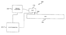
- FIG. 2 is a schematic diagram of a head-disc interference detection system in accordance with a preferred embodiment of the present invention.
- FIG. 3 is a flow chart depicting a process flow for detecting and quantifying head-disc interference in accordance with a preferred embodiment of the present invention.
- FIG. 4 is a diagram illustrating a head path including no runout, a head path including only repeatable runout, and a head path including both repeatable and non-repeatable runout.
- FIG. 5 is a chart depicting the non-repeatable runout component of a position error signal with a disc drive operating in an environment having a pressure equivalent to atmospheric pressure at sea level.
- FIG. 6 is a chart similar to FIG. 5, but with the disc drive operating in an environment having a pressure equivalent to atmospheric pressure at 5,000 feet above sea level.
- FIG. 7 is a chart similar to FIG. 5, but with the disc drive operating in an environment having a pressure equivalent to atmospheric pressure at 10,000 feet above sea level.
- FIG. 8 is a chart similar to FIG. 5, but with the disc drive operating in an environment having a pressure equivalent to atmospheric pressure at 13,000 feet above sea level.
- FIG. 9 is a flow chart depicting in detail a process flow for detecting head-disc interference in accordance with a preferred embodiment of the present invention.
- A
disc drive 100 constructed in accordance with a preferred embodiment of the present invention is shown in FIG. 1. Thedisc drive 100 includes abase 102 to which various components of thedisc drive 100 are mounted. Atop cover 104, shown partially cut away, cooperates with thebase 102 to form an internal, sealed environment for the disc drive in a conventional manner. The components include aspindle motor 106, which rotates one ormore discs 108 at a constant high speed. Information is written to and read from tracks on thediscs 108 through the use of an actuator assembly 110, which rotates during a seek operation about abearing shaft assembly 112 positioned adjacent thediscs 108. The actuator assembly 110 includes a plurality of actuator arms 114 which extend towards thediscs 108, with one ormore flexures 116 extending from each of the actuator arms 114. Mounted at the distal end of each of theflexures 116 is ahead 118, which includes an air bearing slider enabling thehead 118 to fly in close proximity above the corresponding surface of the associateddisc 108. - During a seek operation, the track position of the
heads 118 is controlled through the use of avoice coil motor 124, which typically includes acoil 126 attached to the actuator assembly 110, as well as one or morepermanent magnets 128 which establish a magnetic field in which thecoil 126 is immersed. The controlled application of current to thecoil 126 causes magnetic interaction between thepermanent magnets 128 and thecoil 126 so that thecoil 126 moves in accordance with the well-known Lorentz relationship. As thecoil 126 moves, the actuator assembly 110 pivots about thebearing shaft assembly 112, and theheads 118 are caused to move across the surfaces of thediscs 108. - The
spindle motor 106 is typically de-energized when thedisc drive 100 is not in use for extended periods of time. Theheads 118 are moved overpark zones 120 near the inner diameter of thediscs 108 when the drive motor is de-energized. Theheads 118 are secured over thepark zones 120 through the use of an actuator latch arrangement, which prevents inadvertent rotation of the actuator assembly 110 when the heads are parked. - A
flex assembly 130 provides the requisite electrical connection paths for the actuator assembly 110 while allowing pivotal movement of the actuator assembly 110 during operation. The flex assembly includes a printedcircuit board 132 to which head wires (not shown) are connected; the head wires being routed along the actuator arms 114 and theflexures 116 to theheads 118. The printedcircuit board 132 typically includes circuitry for controlling the write currents applied to theheads 118 during a write operation and a preamplifier for amplifying read signals generated by theheads 118 during a read operation. The flex assembly terminates at aflex bracket 134 for communication through thebase deck 102 to a disc drive printed circuit board (not shown) mounted to the bottom side of thedisc drive 100. - Embodiments of the present invention may be implemented either through hardware, i.e., logic devices, or as a computer-readable program storage device which tangibly embodies a program of instructions executable by a
disc drive 100 or other computer system for detecting and quantifying head-disc interference using position error signals. As such, the logical operations of the various embodiments of the present invention may be implemented (1) as a sequence of computer implemented acts or program modules running on a computing system and/or (2) as interconnected machine logic circuits or circuit modules within the computing system. The implementation is a matter of choice dependent on the performance requirements of the computing system implementing the invention. Accordingly, the logical operations making up the embodiments of the present invention described herein are referred to variously as operations, structural devices, acts or modules. It will be recognized by one skilled in the art that these operations, structural devices, acts and modules may be implemented in software, in firmware, in special purpose digital logic, and any combination thereof without deviating from the spirit and scope of the present invention as recited within the claims attached hereto. - FIG. 2 depicts a
system 200 for detecting and quantifying head-disc interference (i.e., contact between a head and data surface of a disc while the disc drive is operating). The head-discinterference detection system 200 includes adisc 108 and ahead 118 flying at afly height 204 over thedisc 108. While thehead 118 is generally flying at aparticular fly height 204, it may come into contact with thedisc 108 for various reasons, but particularly if thefly height 204 is too small. - A head-disc
interference determination module 210 receives a position error signal, which represents the deviation of thehead 118 from a track of thedisc 108. The head-discinterference determination module 210 uses the position error signal to determine whether the level of head-disc interference is too great. Apreload adjustment module 220 can then adjust thefly height 204 by adjusting the preload on the head 118 (i.e., a force between thehead 118 and thedisc 108 when thehead 118 is resting on the disc 108). Alternatively, thefly height 204 can be adjusted by replacing thehead 118. Preload adjustment may be done, for example, by heating a portion of theflexure 116 that supports thehead 118. The head-discinterference determination module 210 may again determine whether the level of interference between thehead 118 and thedisc 108 is too great. This iterative process may continue until a desiredfly height 204 is achieved. - A process flow for determining whether the level of interference between the
head 118 and thedisc 108 is too great is depicted in FIG. 3. In obtain positionerror signal operation 230, a position error signal is received from thesubject head 118. A value of the position error signal is then determined in determine position errorsignal value operation 240. The position error signal value is preferably a statistical summation of at least a portion of the position error signal, although it could be some other value calculated from the position error signal, such as a peak value at a specific frequency. - The position error signal value is compared to a benchmark value in compare
operation 242. The benchmark value is preferably such that position error signal values above the benchmark value indicate unacceptable levels of head-disc interference and position error signal values below the benchmark value indicate acceptable levels of head-disc interference.Benchmark query operation 244 determines whether the position error signal value is above or below the benchmark value. If the position error signal value is above the benchmark value, then thedisc drive 100 fails, indicating that the level of head-disc interference between thehead 118 and thedisc 108 is too great. Such adisc drive 100 has a high likelihood of a head crash or similar problems and can be scrapped, or more preferably reworked by adjusting the preload on thehead 118 or replacing thehead 118. - The position error signal typically includes both repeatable and non-repeatable runout components. FIG. 4 illustrates what is meant by repeatable and non-repeatable runout components. As a
head 118 travels over adisc 108, thehead 118 will stray from anideal track path 260. A repeatablerunout track path 262 depicts the path of ahead 118 if it had only repeatable runout and no non-repeatable runout. The deviation due to the repeatable runout is repeated on each revolution of thedisc 108. Anactual track path 264 illustrates the actual path followed by thehead 118, including the repeatable and non-repeatable runout components. The non-repeatable runout component is not repeated on each revolution, and often results from vibrations in thedisc drive 100. - Vibrations caused by head-disc interference are manifest most clearly in the non-repeatable component of the position error signal. FIGS. 5-8 illustrate the effects of head-disc interference on the non-repeatable runout component of the position error signal. FIGS. 5-8 illustrate the non-repeatable runout position error signals in the frequency domain for a disc drive operating in each of four different environmental pressures: a pressure equivalent to typical atmospheric pressure at sea level, a pressure equivalent to typical atmospheric pressure at 5,000 ft above sea level, a pressure equivalent to typical atmospheric pressure at 10,000 ft above sea level, and a pressure equivalent to typical atmospheric pressure at 13,000 ft above sea level.
- Each chart in FIGS. 5-8 includes a
vertical axis 310 that represents the non-repeatable runout component of the position error signal, and ahorizontal axis 312 that represents frequency. As shown in FIG. 5, a sealevel magnitude line 314 represents the non-repeatable runout component of the position error signal when operating thedisc drive 100 in a sea level equivalent pressure environment. The sealevel magnitude line 314 includes alow frequency portion 316 having several sharp peaks below 4,000 Hz and an increase at about 7,000 Hz. However, the sealevel magnitude line 314 is stable with no significant increases along ahigh frequency portion 318 from 8,000 Hz to above 12,000 Hz. - FIG. 6 shows a 5,000
ft magnitude line 324 representing the position error signal of thedisc drive 100 operating in a 5,000 ft altitude equivalent pressure environment. At that decreased pressure, thefly height 204 of thehead 118 is lower. Alow frequency portion 326 of the 5,000ft magnitude line 324 is similar to thelow frequency portion 316 of the sealevel magnitude line 314, but with slightly higher peaks. The 5,000ft magnitude line 324 still includes no noticeable increases in itshigh frequency portion 328 from 8,000 Hz to above 12,000 Hz. This indicates that the fly height has not decreased enough to cause significant head-disc interference. - FIG. 7 illustrates a 10,000
ft magnitude line 334 representing the position error signal of thedisc drive 100 operating in a 10,000 ft altitude equivalent pressure environment. Again, alow frequency portion 336 of the 10,000 ft magnitude line is similar to thelow frequency portions high frequency portion 338 of the 10,000 ft magnitude line defines several peaks around 12,000 Hz. These increases in the high frequency range of the non-repeatable runout component of the position error signal indicate the further decreased fly height in the 10,000 ft altitude equivalent pressure environment has resulted in significant head-disc interference, which has likely excited the high resonant frequencies in the actuator arms and/or flexures. - Finally, FIG. 8 illustrates a 13,000 ft magnitude line that represents the position error signal of the
disc drive 100 operating at a pressure equivalent to atmospheric pressure at 13,000 ft above sea level. Thelow frequency portion 346 of the 13,000ft magnitude line 344 is once again similar to thelow frequency portions large peaks 350 emerge in thehigh frequency portion 348 above 10,000 Hz. It is believed that each of these peaks corresponds to one of the resonant frequency vibration modes in the actuator arms or flexures, indicating that even more head disc interference is occurring in the 13,000 ft equivalent pressure environment than in the 10,000 ft equivalent pressure environment. - Notably, head-disc interference appears to cause more severe vibrations at the higher resonant frequencies of the actuator arms and/or flexures. However, the lower frequency peaks also appear to increase as the level of head-disc interference increases, though not as dramatically as the higher frequencies.
- Several values obtained from the non-repeatable runout component of the position error signal could each be used separately to detect head-disc interference. For example, in a preferred embodiment, a root mean square value of the portion of the signal above 10,000 Hz is calculated and compared to a benchmark value. If the root mean square value exceeds the benchmark value, then the head-disc interference is either significant or unacceptable, depending on the chosen benchmark value. In other words, a relatively low benchmark could be used to detect significant head-disc interference, while a higher benchmark could be used to detect head-disc interference that is not only significant, but also unacceptable. Alternatively, the entire signal could be summed in either the time or frequency domain. Indeed, the peak value at one of the high-frequency resonant modes could be compared to a benchmark value.
- FIG. 9 illustrates a process flow for detecting head-disc interference. In an obtain PES operation 410, a position error signal of the
disc drive 100 is obtained. Intransform PES operation 412, the position error signal is preferably transformed into the frequency domain, such as by performing a fast Fourier transform on the signal. In subtractrepeatable runout operation 414, the repeatable runout component of the position error signal is subtracted from the position error signal to yield the non-repeatable runout component of the position error signal. In highpass filter operation 420, a high pass filter filters out portions of the position error signal that are below a predetermined minimum frequency. Preferably, the predetermined minimum frequency is lower than high frequency peaks that are excited by head-disc interference. In a preferred embodiment, the predetermined minimum frequency is 10,000 Hz so that the resulting signal only includes frequencies above 10,000 Hz. Theoperations - In root sum
square operation 422, a root sum square of the peak values in the resulting signal is calculated. In benchmark compareoperation 424, the root sum square value is compared to a predetermined benchmark value. The benchmark value is preferably determined such that root sum square values above the benchmark value indicate unacceptable or significant levels of head-disc interference and root sum square values below the benchmark value indicate acceptable or insignificant levels of head-disc interference. In abenchmark query operation 426, it is determined whether the root sum square value calculated in root sumsquare operation 422 is above or below the benchmark value. If the root sum square value is less than the benchmark value, then thedisc drive 100 passes. If the root sum square value is more than the benchmark value, then thedisc drive 100 fails. If thedisc drive 100 fails, it can be reworked or redesigned as described above, or it can be scrapped. - An embodiment of the present invention may be described as a method of detecting and quantifying head-disc interference in a disc drive (such as 100). The method includes obtaining a position error signal representing deviation of a head (such as 118) from a track on a disc (such as 108) in the disc drive. A portion of the position error signal is analyzed to produce a signal value that corresponds to a level of head-disc interference in the disc drive. The signal value is compared to a predetermined benchmark value, thereby quantifying head-disc interference in the disc drive. Moreover, the method may include designating the disc drive as unacceptable if the signal value is above the predetermined benchmark value.
- The analysis of the position error signal may include analyzing a portion of a non-repeatable runout component of the position error signal. Additionally, the analysis may include transforming the position error signal into a frequency domain and analyzing a portion of the frequency domain of the position error signal. Preferably, the portion of the frequency domain is above a predetermined lower frequency limit, which may be about ten thousand Hertz. Moreover, the analysis may include calculating a root sum square of the portion of the position error signal. The method may further include adjusting a preload between the head and the disc surface if the signal value is above the benchmark value.
- An embodiment of the present invention may be alternatively described as a method of detecting and quantifying head-disc interference. The method includes obtaining a position error signal representing deviation of a head (such as 118) from a track of a data surface of a disc (such as 108) and isolating a non-repeatable runout component of the position error signal. A portion of the non-repeatable runout component is analyzed to produce a signal value, and the signal value is compared to a predetermined benchmark value, thereby quantifying head-disc interference in the disc drive.
- Stated yet another way, an embodiment of the present invention may be alternatively described as a head-disc interference detection system adapted to detect and quantify contact between discs (such as 108) and heads (such as 118) positioned over data surfaces of the discs in disc drives (such as 100). The system includes a disc drive (such as 100) including a disc (such as 108) and a head (such as 118) positioned over a data surface of the disc. The head is able to produce a position error signal representing deviation of the head from a track of the data surface. The detection system is able to analyze magnitudes of the position error signal to produce a signal value. The detection system is also able to compare the signal value to a predetermined benchmark value, thereby quantifying head-disc interference in the disc drive.
- It will be clear that the present invention is well adapted to attain the ends and advantages mentioned as well as those inherent therein. While a presently preferred embodiment has been described for purposes of this disclosure, various changes and modifications may be made which are well within the scope of the present invention. For example, a frequency band, a low pass region, or even the entire position error signal in the time or frequency domain could be summed to yield a position error signal value to be compared to a benchmark value. Numerous other changes may be made which will readily suggest themselves to those skilled in the art and which are encompassed in the spirit of the invention disclosed and as defined in the appended claims.
Claims (20)
1. A method of detecting and quantifying head-disc interference in a disc drive, the method comprising steps of:
(a) obtaining a position error signal representing deviation of a head from a track on a disc in the disc drive;
(b) analyzing a portion of the position error signal to produce a signal value that corresponds to a level of head-disc interference in the disc drive; and
(c) comparing the signal value to a predetermined benchmark value, thereby quantifying head-disc interference in the disc drive.
2. The method of claim 1 , further comprising a step of:
(d) designating the disc drive as unacceptable if the signal value is above the predetermined benchmark value.
3. The method of claim 1 , wherein the analyzing step (b) comprises analyzing a portion of a non-repeatable runout component of the position error signal.
4. The method of claim 1 , wherein the analyzing step (b) comprises:
(b)(i) transforming the position error signal into a frequency domain; and
(b)(ii) analyzing a portion of the frequency domain of the position error signal.
5. The method of claim 4 , wherein the portion of the frequency domain is above a predetermined lower frequency limit.
6. The method of claim 4 , wherein the lower limit is about ten thousand Hertz.
7. The method of claim 1 , further comprising a step of:
(d) adjusting a preload between the head and the disc surface if the signal value is above the benchmark value.
8. The method of claim 1 , wherein the analyzing step (b) comprises calculating a root sum square of the portion of the position error signal.
9. In a disc drive having a disc and a head positioned over a data surface of the disc, a method of detecting and quantifying head-disc interference, the method comprising steps of:
(a) obtaining a position error signal representing deviation of the head from a track of the data surface;
(b) isolating a non-repeatable runout component of the position error signal;
(c) analyzing a portion of the non-repeatable runout component to produce a signal value; and
(d) comparing the signal value to a predetermined benchmark value, thereby quantifying head-disc interference in the disc drive.
10. The method of claim 9 , further comprising a step of:
(e) designating the disc drive as unacceptable if the signal value exceeds the benchmark value.
11. The method of claim 9 , wherein the analyzing step (c) comprises:
(c)(i) transforming the non-repeatable runout component of the position error signal into a frequency domain; and
(c)(ii) statistically summing magnitudes of the non-repeatable runout component from a portion of the frequency domain.
12. The method of claim 11 , wherein the portion of the frequency domain is above a predetermined lower frequency limit.
13. The method of claim 12 , wherein the lower limit is about ten thousand Hertz.
14. The method of claim 11 , wherein the summing step (c)(ii) comprises calculating a root sum square of the magnitudes of the non-repeatable runout component.
15. The method of claim 9 , further comprising:
(e) adjusting a preload between the head and the disc surface if the signal value is above the benchmark value.
16. A head-disc interference detection system adapted to detect and quantify contact between discs and heads positioned over data surfaces of the discs in disc drives, the system comprising:
a disc drive including a disc and a head positioned over a data surface of the disc, the head adapted to produce a position error signal representing deviation of the head from a track of the data surface, wherein the detection system is adapted to analyze magnitudes of the position error signal to produce a signal value and to compare the signal value to a predetermined benchmark value, thereby quantifying head-disc interference in the disc drive.
17. The system of claim 16 , wherein a signal value above the predetermined benchmark value indicates an unacceptable level of contact between the head and the disc surface.
18. The system of claim 16 , wherein the detection system is adapted to sum magnitudes of a non-repeatable runout portion of the position error signal.
19. The system of claim 16 , wherein the detection system is adapted to transform the position error signal into frequency domain and to statistically sum magnitudes from only a portion of the frequency domain that is above a predetermined lower frequency limit.
20. The system of claim 16 , wherein the detection system is adapted to decrease a preload between the head and the disc surface if the signal value is above the benchmark value.
Priority Applications (1)
| Application Number | Priority Date | Filing Date | Title |
|---|---|---|---|
| US10/215,907 US20030193727A1 (en) | 2002-04-11 | 2002-08-08 | Detecting head-disc interference using position error signal |
Applications Claiming Priority (2)
| Application Number | Priority Date | Filing Date | Title |
|---|---|---|---|
| US37251502P | 2002-04-11 | 2002-04-11 | |
| US10/215,907 US20030193727A1 (en) | 2002-04-11 | 2002-08-08 | Detecting head-disc interference using position error signal |
Publications (1)
| Publication Number | Publication Date |
|---|---|
| US20030193727A1 true US20030193727A1 (en) | 2003-10-16 |
Family
ID=28794118
Family Applications (1)
| Application Number | Title | Priority Date | Filing Date |
|---|---|---|---|
| US10/215,907 Abandoned US20030193727A1 (en) | 2002-04-11 | 2002-08-08 | Detecting head-disc interference using position error signal |
Country Status (1)
| Country | Link |
|---|---|
| US (1) | US20030193727A1 (en) |
Cited By (14)
| Publication number | Priority date | Publication date | Assignee | Title |
|---|---|---|---|---|
| WO2006022976A2 (en) * | 2004-08-24 | 2006-03-02 | Iomega Corporation | Detection of fly height change in a disk drive |
| US7158325B1 (en) * | 2003-11-06 | 2007-01-02 | Maxtor Corporation | Disk drive head touchdown detection with improved discrimination |
| US7245452B1 (en) * | 2005-03-04 | 2007-07-17 | Maxtor Corporation | Disk drive with altitude detection via analysis of non-repeatable runout components |
| US20070271480A1 (en) * | 2006-05-16 | 2007-11-22 | Samsung Electronics Co., Ltd. | Method and apparatus to conceal error in decoded audio signal |
| US7362534B1 (en) * | 2004-04-08 | 2008-04-22 | Maxtor Corporation | System for detecting a change in head-to-disk contact status in a disk drive |
| US7391586B2 (en) | 2005-09-30 | 2008-06-24 | Seagate Technology Llc | Servowriter ramp detection |
| US20080170315A1 (en) * | 2007-01-12 | 2008-07-17 | Seagate Technology, Llc | Spectral analysis of a position error signal |
| US7411389B1 (en) | 2004-04-08 | 2008-08-12 | Maxtor Corporation | Method of detecting changes in operability status of a slider mover in a disk drive |
| US20090128947A1 (en) * | 2007-11-15 | 2009-05-21 | Western Digital (Fremont), Llc | Disk drive determining operating fly height by detecting head disk contact from disk rotation time |
| US20090296262A1 (en) * | 2008-05-29 | 2009-12-03 | Fujitsu Limited | Flying height control method and circuit |
| US20100073799A1 (en) * | 2008-09-24 | 2010-03-25 | Seagate Technology Llc | Detecting contact between a slider and a data storage medium without a seperate contact-detection voltage source |
| US20110075291A1 (en) * | 2009-09-25 | 2011-03-31 | Samsung Electronics Co., Ltd. | Disk drive controlled to detect head-disk interference |
| US8934192B1 (en) | 2008-11-24 | 2015-01-13 | Western Digital Technologies, Inc. | Disk drive determining operating fly height by detecting head disk contact from read signal amplitude variance |
| US9349401B1 (en) | 2014-07-24 | 2016-05-24 | Western Digital Technologies, Inc. | Electronic system with media scan mechanism and method of operation thereof |
Citations (9)
| Publication number | Priority date | Publication date | Assignee | Title |
|---|---|---|---|---|
| US5539592A (en) * | 1994-10-05 | 1996-07-23 | International Business Machines Corporation | System and method for monitoring friction between head and disk to predict head disk interaction failure in direct access storage devices |
| US6057975A (en) * | 1994-10-11 | 2000-05-02 | Seagate Technology, Inc. | Fly height adjustment in magnetic storage system |
| US6097559A (en) * | 1998-06-26 | 2000-08-01 | International Business Machines Corporation | System and method for detecting head-to-disk contact in-situ a direct access storage device using a position error signal |
| US6105240A (en) * | 1997-10-16 | 2000-08-22 | Seagate Technology, Inc. | Dynamic balance measurement station for a disc drive |
| US6142006A (en) * | 1997-07-25 | 2000-11-07 | Seagate Technology Llc | Method and apparatus for calibrating a glide head and detection system for a magnetic disk drive |
| US6344949B1 (en) * | 1999-07-13 | 2002-02-05 | International Business Machines Corporation | Flying height adjustment for air bearing sliders |
| US6522495B1 (en) * | 1999-04-16 | 2003-02-18 | International Business Machines Corporation | System, method and program for determining the magnetic center shift within a disk drive system |
| US6636376B1 (en) * | 1999-10-12 | 2003-10-21 | Seagate Technology Llc | Disc drive resonance disturbance cancellation filter |
| US6747824B1 (en) * | 2000-05-26 | 2004-06-08 | Hitachi Global Storage Technologies Netherlands, B.V. | Method and apparatus for head crash predictive failure analysis based upon slider track misregistration measurement using the readback signal |
-
2002
- 2002-08-08 US US10/215,907 patent/US20030193727A1/en not_active Abandoned
Patent Citations (10)
| Publication number | Priority date | Publication date | Assignee | Title |
|---|---|---|---|---|
| US5539592A (en) * | 1994-10-05 | 1996-07-23 | International Business Machines Corporation | System and method for monitoring friction between head and disk to predict head disk interaction failure in direct access storage devices |
| US6057975A (en) * | 1994-10-11 | 2000-05-02 | Seagate Technology, Inc. | Fly height adjustment in magnetic storage system |
| US6142006A (en) * | 1997-07-25 | 2000-11-07 | Seagate Technology Llc | Method and apparatus for calibrating a glide head and detection system for a magnetic disk drive |
| US6293135B1 (en) * | 1997-07-25 | 2001-09-25 | Seagate Technology Llc | Method of calibrating a system for detecting contact of a glide head with a recording media surface |
| US6105240A (en) * | 1997-10-16 | 2000-08-22 | Seagate Technology, Inc. | Dynamic balance measurement station for a disc drive |
| US6097559A (en) * | 1998-06-26 | 2000-08-01 | International Business Machines Corporation | System and method for detecting head-to-disk contact in-situ a direct access storage device using a position error signal |
| US6522495B1 (en) * | 1999-04-16 | 2003-02-18 | International Business Machines Corporation | System, method and program for determining the magnetic center shift within a disk drive system |
| US6344949B1 (en) * | 1999-07-13 | 2002-02-05 | International Business Machines Corporation | Flying height adjustment for air bearing sliders |
| US6636376B1 (en) * | 1999-10-12 | 2003-10-21 | Seagate Technology Llc | Disc drive resonance disturbance cancellation filter |
| US6747824B1 (en) * | 2000-05-26 | 2004-06-08 | Hitachi Global Storage Technologies Netherlands, B.V. | Method and apparatus for head crash predictive failure analysis based upon slider track misregistration measurement using the readback signal |
Cited By (25)
| Publication number | Priority date | Publication date | Assignee | Title |
|---|---|---|---|---|
| US7158325B1 (en) * | 2003-11-06 | 2007-01-02 | Maxtor Corporation | Disk drive head touchdown detection with improved discrimination |
| US7362534B1 (en) * | 2004-04-08 | 2008-04-22 | Maxtor Corporation | System for detecting a change in head-to-disk contact status in a disk drive |
| US7509728B1 (en) | 2004-04-08 | 2009-03-31 | Maxtor Corporation | Method for adjusting head-to-disk spacing in a disk drive |
| US7486459B1 (en) | 2004-04-08 | 2009-02-03 | Maxtor Corporation | Disk drive with performance driven head-to-disk spacing |
| US7411389B1 (en) | 2004-04-08 | 2008-08-12 | Maxtor Corporation | Method of detecting changes in operability status of a slider mover in a disk drive |
| US20080013198A1 (en) * | 2004-08-24 | 2008-01-17 | Iomega Corporation | Detection of Fly Height Change in a Disk Drive |
| WO2006022976A2 (en) * | 2004-08-24 | 2006-03-02 | Iomega Corporation | Detection of fly height change in a disk drive |
| US7567398B2 (en) | 2004-08-24 | 2009-07-28 | Iomega Corporation | Detection of fly height change in a disk drive |
| US20060044658A1 (en) * | 2004-08-24 | 2006-03-02 | Yiping Ma | Detection of fly height change in a disk drive |
| WO2006022976A3 (en) * | 2004-08-24 | 2006-12-21 | Iomega Corp | Detection of fly height change in a disk drive |
| US7245452B1 (en) * | 2005-03-04 | 2007-07-17 | Maxtor Corporation | Disk drive with altitude detection via analysis of non-repeatable runout components |
| US7391586B2 (en) | 2005-09-30 | 2008-06-24 | Seagate Technology Llc | Servowriter ramp detection |
| US8798172B2 (en) * | 2006-05-16 | 2014-08-05 | Samsung Electronics Co., Ltd. | Method and apparatus to conceal error in decoded audio signal |
| US20070271480A1 (en) * | 2006-05-16 | 2007-11-22 | Samsung Electronics Co., Ltd. | Method and apparatus to conceal error in decoded audio signal |
| US20080170315A1 (en) * | 2007-01-12 | 2008-07-17 | Seagate Technology, Llc | Spectral analysis of a position error signal |
| US7742250B2 (en) | 2007-01-12 | 2010-06-22 | Seagate Technology Llc | Spectral analysis of a position error signal |
| US20090128947A1 (en) * | 2007-11-15 | 2009-05-21 | Western Digital (Fremont), Llc | Disk drive determining operating fly height by detecting head disk contact from disk rotation time |
| US7583466B2 (en) | 2007-11-15 | 2009-09-01 | Western Digital (Fremont), Llc | Disk drive determining operating fly height by detecting head disk contact from disk rotation time |
| US20090296262A1 (en) * | 2008-05-29 | 2009-12-03 | Fujitsu Limited | Flying height control method and circuit |
| US7692890B2 (en) * | 2008-05-29 | 2010-04-06 | Toshiba Storage Device Corporation | Flying height control method and circuit |
| US20100073799A1 (en) * | 2008-09-24 | 2010-03-25 | Seagate Technology Llc | Detecting contact between a slider and a data storage medium without a seperate contact-detection voltage source |
| US7952829B2 (en) * | 2008-09-24 | 2011-05-31 | Seagate Technology Llc | Detecting contact between a slider and a data storage medium without a separate contact-detection voltage source |
| US8934192B1 (en) | 2008-11-24 | 2015-01-13 | Western Digital Technologies, Inc. | Disk drive determining operating fly height by detecting head disk contact from read signal amplitude variance |
| US20110075291A1 (en) * | 2009-09-25 | 2011-03-31 | Samsung Electronics Co., Ltd. | Disk drive controlled to detect head-disk interference |
| US9349401B1 (en) | 2014-07-24 | 2016-05-24 | Western Digital Technologies, Inc. | Electronic system with media scan mechanism and method of operation thereof |
Similar Documents
| Publication | Publication Date | Title |
|---|---|---|
| US6683737B2 (en) | Method and apparatus for predictive failure analysis technique for head crashes in hard drives using position error signal | |
| US7215495B1 (en) | System and method for determining head-disk contact in a magnetic recording disk drive | |
| US7292401B2 (en) | System and method for determining head-disk contact in a magnetic recording disk drive by magnetoresistive signal amplitude | |
| US7918013B1 (en) | System for manufacturing a group of head gimbal assemblies (HGAs) | |
| US20030193727A1 (en) | Detecting head-disc interference using position error signal | |
| US20060215309A1 (en) | Low flying head detection using readback signal amplitude modulation | |
| US7391586B2 (en) | Servowriter ramp detection | |
| US20030002183A1 (en) | Head contact detector | |
| KR20010110342A (en) | Method and apparatus for reducing track misregistration from servo track writing | |
| US8405927B2 (en) | Apparatus and method for detecting low flying sliders | |
| US6956707B2 (en) | Method for look-ahead thermal sensing in a data storage device | |
| US20110085260A1 (en) | Disk drive and servo control method for the disk drive that is responsive to vibration | |
| JP2008071388A (en) | Defect inspection method and apparatus for magnetic disk, and magnetic disk drive | |
| US8274751B2 (en) | Electrical current as probe for modulation at head-disk interface | |
| KR100455258B1 (en) | Sensor system and flying height testing method for disk device using floated head | |
| US20040021977A1 (en) | Compensating for coherent runout error in a data-storage device | |
| US20080247078A1 (en) | Altitude sensing systems and methods for fly height adjustment | |
| US6445520B1 (en) | Method for detecting mechanical damage in a parking zone of a hard disk drive | |
| US7430083B2 (en) | Virtual head fly profile measurement | |
| JP4276256B2 (en) | Detection of slider / disk interference using dynamic parametric testing | |
| US20070159727A1 (en) | Method and system for utilizing flexible members in a head gimbal assembly to reduce impact of operational disturbances of slider flying height | |
| US20100238585A1 (en) | Method of controlling flying height of magnetic head of hard disk drive | |
| US20080074116A1 (en) | Advanced air bearing and detection method for media glide testing at ultra-low flying height | |
| US8225655B2 (en) | Altitude sensing systems for flying height adjustment | |
| US7259931B2 (en) | Slider design for high fly write immunity |
Legal Events
| Date | Code | Title | Description |
|---|---|---|---|
| AS | Assignment |
Owner name: SEAGATE TECHNOLOGY LLC, CALIFORNIA Free format text: ASSIGNMENT OF ASSIGNORS INTEREST;ASSIGNORS:FIORAVANTI, LOUIS J.;WOOD, JOSEPH A.;HO, HAI T.;REEL/FRAME:013190/0730 Effective date: 20020806 |
|
| STCB | Information on status: application discontinuation |
Free format text: ABANDONED -- FAILURE TO RESPOND TO AN OFFICE ACTION |