US20030194483A1 - Grease rework applicator - Google Patents
Grease rework applicator Download PDFInfo
- Publication number
- US20030194483A1 US20030194483A1 US10/122,253 US12225302A US2003194483A1 US 20030194483 A1 US20030194483 A1 US 20030194483A1 US 12225302 A US12225302 A US 12225302A US 2003194483 A1 US2003194483 A1 US 2003194483A1
- Authority
- US
- United States
- Prior art keywords
- slider
- grease
- unit
- cavity
- cap
- Prior art date
- Legal status (The legal status is an assumption and is not a legal conclusion. Google has not performed a legal analysis and makes no representation as to the accuracy of the status listed.)
- Granted
Links
Images


Classifications
-
- G—PHYSICS
- G06—COMPUTING; CALCULATING OR COUNTING
- G06F—ELECTRIC DIGITAL DATA PROCESSING
- G06F1/00—Details not covered by groups G06F3/00 - G06F13/00 and G06F21/00
- G06F1/16—Constructional details or arrangements
- G06F1/20—Cooling means
-
- H—ELECTRICITY
- H01—ELECTRIC ELEMENTS
- H01L—SEMICONDUCTOR DEVICES NOT COVERED BY CLASS H10
- H01L23/00—Details of semiconductor or other solid state devices
- H01L23/34—Arrangements for cooling, heating, ventilating or temperature compensation ; Temperature sensing arrangements
- H01L23/42—Fillings or auxiliary members in containers or encapsulations selected or arranged to facilitate heating or cooling
-
- H—ELECTRICITY
- H01—ELECTRIC ELEMENTS
- H01L—SEMICONDUCTOR DEVICES NOT COVERED BY CLASS H10
- H01L2924/00—Indexing scheme for arrangements or methods for connecting or disconnecting semiconductor or solid-state bodies as covered by H01L24/00
- H01L2924/0001—Technical content checked by a classifier
- H01L2924/0002—Not covered by any one of groups H01L24/00, H01L24/00 and H01L2224/00
Definitions
- the present invention relates in general to methods and apparatus for applying a controlled thickness of semi-viscous material to a surface.
- a heat sink assembly is supplied from a heat sink vendor with a controlled amount of thermal grease applied to the base of the heat sink.
- the thermal grease may have a specification that requires the thickness of the thermal grease to be 0.005 inch thick with a variation of plus or minus 0.001 inch.
- the system assembly vendor doing the final board assembly and test would normally attach the heat sink to a corresponding IC. While applying a thickness of thermal grease to the heat sink with high accuracy may be easy to achieve at the heat sink vendor's manufacturing line, any rework required at the system assembly vendor or later in the field makes reproducing the required thermal grease thickness very difficult.
- a thermal grease applicator comprises sub-unit parts that are coupled together to form a thermal grease carrier.
- the thermal grease carrier has a base unit for locating a particular applicator to a corresponding particular heat sink design.
- a cap unit couples to the base and forms a first cavity which has a window opening and a slider opening.
- a slider unit has a cross-section corresponding to the slider opening and a slider bottom surface that forms the top of a grease cavity within the first cavity.
- the grease cavity has a cross-section area and a depth corresponding to a volumetric amount of grease to be applied.
- the grease cavity is filled with thermal grease to a surface of the base unit.
- the filled thermal grease applicator is placed on a surface of the heat sink so that the grease in the grease cavity contacts the surface.
- Pressure is applied to the slider unit by pressing on a top surface of the cap unit. While pressure is being applied, the slider is extracted from the slider opening. The slider moves over the top of the thermal grease in the grease cavity and “planes” the grease surface removing any excess thermal grease, smoothing the top surface of the thermal grease and thereby setting the thickness of the thermal grease. The thermal grease applicator is then lifted from the heat sink leaving a controlled volume of thermal grease.
- FIG. 1 illustrates a base unit of a grease applicator
- FIG. 2 illustrates a cap unit of a grease applicator
- FIG. 3 illustrates a slider unit of a grease applicator
- FIG. 4 illustrates the grease applicator with the base unit, cap unit and slider unit coupled together
- FIG. 5 is a bottom view of a grease carrier showing a grease cavity
- FIG. 6A illustrates a heat sink with a grease applicator attached
- FIG. 6B illustrates the heat sink after the grease applicator has been used to apply a controlled amount of thermal grease
- FIG. 7 is another view of the grease carrier showing the cavities when assembled.
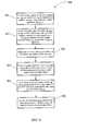
- FIG. 8 is a flow diagram of method steps used in embodiments of the present invention.
- FIG. 1 illustrates base unit 100 of the grease applicator 400 (see FIG. 4).
- Base unit 100 has a window 101 with a predetermined area and depth corresponding to a particular volumetric shaped amount of grease to be applied to a particular heat sink (e.g., heat sink 601 , shown in FIG. 6).
- Base unit 100 has three distinct surfaces, base top surface 107 , base bottom surface 108 and cavity bottom surface 106 .
- Base unit 100 also has three locator slots, 103 - 105 . These locating slots match corresponding location tenons 202 - 204 in the cap unit 200 (see FIG. 2) and are used to locate base unit 100 and cap unit 200 with respect to each other.
- Extension 102 forms a ledge that is mated to one edge of its matching heat sink and functions to locate window 101 so that the grease will be applied on a particular area of the heat sink surface (e.g., surface 603 , shown in FIG. 6).
- Window 101 has a depth corresponding to the thickness of the material between cavity bottom surface 106 and base bottom surface 108 .
- FIG. 2 illustrates cap 200 which mates with base unit 100 .
- Location tenons 202 - 204 mate with locator slots 103 - 105 in base unit 100 .
- Cavity top surface 201 covers window 101 when base unit 100 and cap unit 200 are coupled together with locator tenons 202 - 204 and corresponding locator slots 103 - 105 .
- Cap unit 200 has three distinct surface areas, cap top surface 205 , cap bottom surface 206 and cavity top surface 201 .
- FIG. 3 illustrates slider unit 300 which has a width 302 and a thickness 301 that corresponds to the cross-section of slider opening 801 (see FIG. 8) formed when base unit 100 and cap unit 200 are coupled together.
- the length 303 of slider unit 300 is sized so that it extends a distance 401 when inserted as part of grease applicator 400 (see FIG. 4). This enables a user to grasp slider unit 300 and extract it as part of the process of applying grease to a heat sink (e.g., heat sink 601 ).
- Slider unit 300 has a slider top surface 305 and a slider bottom surface 304 .
- FIG. 4 illustrates grease applicator 400 formed by assembling base unit 100 , cap unit 200 and slider unit 300 .
- Slider unit 300 extends a distance 401 when inserted in slider opening 701 (see FIG. 7). Extension 102 is also visible in this view.
- Slider top surface 305 is parallel and adjacent to cavity top surface 201 (not visible in this view) in cap unit 200 . Pressure is applied to cap top surface 205 which deflects and applies pressure to slider top surface 305 during the grease application process 800 .
- FIG. 5 is a bottom view of assembled grease applicator 400 .
- base unit 100 and cap unit 200 are coupled together and slider unit 300 is inserted into slider opening 701 (see FIG. 7), a cavity 501 is formed.
- Slider bottom surface 304 forms the top of the cavity 501 .
- Cavity 501 is filled to base bottom surface 108 with a desired thermal grease. If the thermal grease is to be applied at a later time, a covering or decal may be attached over cavity 501 (when filled with thermal grease).
- Extension 102 is used to locate grease applicator 400 with respect to a heat sink (e.g., heat sink 601 ).
- Cap unit 200 is shown indicating cap top surface 205 .
- FIG. 6A is a side view of a heat sink 601 with grease applicator 400 in position for applying grease to surface 603 (see FIG. 6B). Cavity 501 , which is hidden, is shown dotted. Pressure 605 is applied to the cap top surface of grease applicator 400 (e.g., with exemplary finger 604 ). The pressure 605 deflects base top surface 205 and puts pressure on slider top surface 305 . This insures that the thermal grease in grease cavity 501 makes good thermal contact with surface 603 of heat sink 601 . While pressure 605 is applied, slider unit 300 is extracted from the grease applicator 400 .
- Pressure 605 is applied to the cap top surface of grease applicator 400 (e.g., with exemplary finger 604 ). The pressure 605 deflects base top surface 205 and puts pressure on slider top surface 305 . This insures that the thermal grease in grease cavity 501 makes good thermal contact with surface 603 of heat sink 601 . While pressure 605 is applied, slider unit 300 is extracted from the grease app
- Slider bottom surface 304 moves across the grease in cavity 501 “smoothing” it to a desired thickness defined by the depth of cavity 501 .
- heat sink 601 is shown with a controlled amount of grease 602 on heat sink surface 603 .
- Slider 300 is shown extracted from coupled base unit 100 and cap unit 200 , which have been lifted from heat sink 601 .
- Surface 102 engages heat sink 601 to locate grease applicator 400 to heat sink surface 603 .
- FIG. 7 is another view of coupled base unit 100 and cap unit 200 which form grease carrier 600 .
- Slider opening 701 for slider 300 is shown along with base top surface 106 .
- Window 101 has a depth 702 (shown dotted) and slider opening 701 has a height 703 (shown dotted).
- Extension 102 on base unit 100 is also shown in this view.
- Cap unit 200 has cap top surface 205 for applying pressure to grease applicator 400 during grease application process 800 .
- FIG. 8 is a flow diagram of method steps used in embodiments of the present invention.
- base unit 100 and cap unit 200 are coupled together with tenons 202 - 204 mating with corresponding slots 103 - 105 forming grease carrier 600 .
- slider unit 300 is inserted in slider opening 701 forming cavity 501 .
- cavity 501 is filled with the desired grease to the base bottom surface 108 .
- grease applicator 400 is positioned over heat sink 601 using extension 102 as a locating edge.
- step 805 pressure 605 is applied to cap top surface 205 (e.g., with exemplary finger 604 ) to insure that the grease makes good contact with surface 603 of heat sink 601 .
- slider unit 300 is extracted from grease applicator 400 creating a uniform thickness of grease 602 .
- step 806 the grease carrier 600 (slider unit 300 has been extracted) is lifted from heat sink 601 leaving a controlled volume of grease 602 with a desired thickness. Any excess grease that remains in base 100 and on slider 300 may be easily wiped clean readying grease applicator 400 for another application process 800 .
Abstract
A grease applicator is assembled from three parts, a base unit, a cap unit and a slider unit. The base unit has tenons that couple with corresponding slots in the cap unit to form a cavity with a window opening on a first surface and a slider opening on a second surface where a plane parallel to the second surface is perpendicular to a plane parallel to the first surface. A slider unit is inserted into the slider opening and forms a top surface to the window opening and forming a window cavity for containing a predetermined amount and volumetric shape of grease. The grease applicator is applied to a heat sink with the grease in the window cavity contacting a surface of the heat sink. The slider unit is extracted while pressure is applied to a surface of the grease applicator applying a uniform volume of grease.
Description
- The present invention relates in general to methods and apparatus for applying a controlled thickness of semi-viscous material to a surface.
- The power density and thermal specification of present high performance processor integrated circuits (ICs) has been driving up the cost and performance of their corresponding heat sink assemblies. As a result, heat sink technology as well as the thermal interface material required between the heat sink and a corresponding integrated circuit have changed. Current thermal solutions used for high performance IC processors require the use of semi-viscous thermal greases to increase thermal conductivity between the IC and its heat sink. These thermal greases create manufacturing problems as well as human factor concerns.
- Typically, a heat sink assembly is supplied from a heat sink vendor with a controlled amount of thermal grease applied to the base of the heat sink. The thermal grease may have a specification that requires the thickness of the thermal grease to be 0.005 inch thick with a variation of plus or minus 0.001 inch. The system assembly vendor doing the final board assembly and test would normally attach the heat sink to a corresponding IC. While applying a thickness of thermal grease to the heat sink with high accuracy may be easy to achieve at the heat sink vendor's manufacturing line, any rework required at the system assembly vendor or later in the field makes reproducing the required thermal grease thickness very difficult.
- There is, therefore, a need for a method and apparatus that enables a controlled thickness of thermal grease to be applied to a heat sink without resorting to complex equipment or sending the heat sink back to the heat sink vendor for rework.
- A thermal grease applicator comprises sub-unit parts that are coupled together to form a thermal grease carrier. The thermal grease carrier has a base unit for locating a particular applicator to a corresponding particular heat sink design. A cap unit couples to the base and forms a first cavity which has a window opening and a slider opening. A slider unit has a cross-section corresponding to the slider opening and a slider bottom surface that forms the top of a grease cavity within the first cavity. The grease cavity has a cross-section area and a depth corresponding to a volumetric amount of grease to be applied. The grease cavity is filled with thermal grease to a surface of the base unit. The filled thermal grease applicator is placed on a surface of the heat sink so that the grease in the grease cavity contacts the surface. Pressure is applied to the slider unit by pressing on a top surface of the cap unit. While pressure is being applied, the slider is extracted from the slider opening. The slider moves over the top of the thermal grease in the grease cavity and “planes” the grease surface removing any excess thermal grease, smoothing the top surface of the thermal grease and thereby setting the thickness of the thermal grease. The thermal grease applicator is then lifted from the heat sink leaving a controlled volume of thermal grease.
- The foregoing has outlined rather broadly the features and technical advantages of the present invention in order that the detailed description of the invention that follows may be better understood. Additional features and advantages of the invention will be described hereinafter which form the subject of the claims of the invention.
- For a more complete understanding of the present invention, and the advantages thereof, reference is now made to the following descriptions taken in conjunction with the accompanying drawings, in which:
- FIG. 1 illustrates a base unit of a grease applicator;
- FIG. 2 illustrates a cap unit of a grease applicator;
- FIG. 3 illustrates a slider unit of a grease applicator;
- FIG. 4 illustrates the grease applicator with the base unit, cap unit and slider unit coupled together;
- FIG. 5 is a bottom view of a grease carrier showing a grease cavity;
- FIG. 6A illustrates a heat sink with a grease applicator attached;
- FIG. 6B illustrates the heat sink after the grease applicator has been used to apply a controlled amount of thermal grease;
- FIG. 7 is another view of the grease carrier showing the cavities when assembled; and
- FIG. 8 is a flow diagram of method steps used in embodiments of the present invention.
- In the following description, numerous specific details are set forth to provide a thorough understanding of the present invention. However, it will be obvious to those skilled in the art that the present invention may be practiced without such specific details. In other instances, well-known processes have been shown in block diagram form in order not to obscure the present invention in unnecessary detail. For the most part, details concerning manufacturing processes and materials composition and the like have been omitted in as much as such details are not necessary to obtain a complete understanding of the present invention and are within the skills of persons of ordinary skill in the relevant art.
- Refer now to the drawings wherein depicted elements are not necessarily shown to scale and wherein like or similar elements are designated by the same reference numeral through the several views.
- FIG. 1 illustrates
base unit 100 of the grease applicator 400 (see FIG. 4).Base unit 100 has awindow 101 with a predetermined area and depth corresponding to a particular volumetric shaped amount of grease to be applied to a particular heat sink (e.g.,heat sink 601, shown in FIG. 6).Base unit 100 has three distinct surfaces,base top surface 107,base bottom surface 108 andcavity bottom surface 106.Base unit 100 also has three locator slots, 103-105. These locating slots match corresponding location tenons 202-204 in the cap unit 200 (see FIG. 2) and are used to locatebase unit 100 andcap unit 200 with respect to each other.Extension 102 forms a ledge that is mated to one edge of its matching heat sink and functions to locatewindow 101 so that the grease will be applied on a particular area of the heat sink surface (e.g.,surface 603, shown in FIG. 6).Window 101 has a depth corresponding to the thickness of the material betweencavity bottom surface 106 andbase bottom surface 108. - FIG. 2 illustrates
cap 200 which mates withbase unit 100. Location tenons 202-204 mate with locator slots 103-105 inbase unit 100.Cavity top surface 201 coverswindow 101 whenbase unit 100 andcap unit 200 are coupled together with locator tenons 202-204 and corresponding locator slots 103-105.Cap unit 200 has three distinct surface areas,cap top surface 205,cap bottom surface 206 andcavity top surface 201. - FIG. 3 illustrates
slider unit 300 which has awidth 302 and athickness 301 that corresponds to the cross-section of slider opening 801 (see FIG. 8) formed whenbase unit 100 andcap unit 200 are coupled together. Thelength 303 ofslider unit 300 is sized so that it extends adistance 401 when inserted as part of grease applicator 400 (see FIG. 4). This enables a user to graspslider unit 300 and extract it as part of the process of applying grease to a heat sink (e.g., heat sink 601).Slider unit 300 has aslider top surface 305 and aslider bottom surface 304. - FIG. 4 illustrates
grease applicator 400 formed by assemblingbase unit 100,cap unit 200 andslider unit 300.Slider unit 300 extends adistance 401 when inserted in slider opening 701 (see FIG. 7).Extension 102 is also visible in this view.Slider top surface 305 is parallel and adjacent to cavity top surface 201 (not visible in this view) incap unit 200. Pressure is applied to captop surface 205 which deflects and applies pressure to slidertop surface 305 during thegrease application process 800. - FIG. 5 is a bottom view of assembled
grease applicator 400. Whenbase unit 100 andcap unit 200 are coupled together andslider unit 300 is inserted into slider opening 701 (see FIG. 7), acavity 501 is formed.Slider bottom surface 304 forms the top of thecavity 501.Cavity 501 is filled to basebottom surface 108 with a desired thermal grease. If the thermal grease is to be applied at a later time, a covering or decal may be attached over cavity 501 (when filled with thermal grease).Extension 102 is used to locategrease applicator 400 with respect to a heat sink (e.g., heat sink 601).Cap unit 200 is shown indicating captop surface 205. - FIG. 6A is a side view of a
heat sink 601 withgrease applicator 400 in position for applying grease to surface 603 (see FIG. 6B).Cavity 501, which is hidden, is shown dotted.Pressure 605 is applied to the cap top surface of grease applicator 400 (e.g., with exemplary finger 604). Thepressure 605 deflects basetop surface 205 and puts pressure on slidertop surface 305. This insures that the thermal grease ingrease cavity 501 makes good thermal contact withsurface 603 ofheat sink 601. Whilepressure 605 is applied,slider unit 300 is extracted from thegrease applicator 400.Slider bottom surface 304 moves across the grease incavity 501 “smoothing” it to a desired thickness defined by the depth ofcavity 501. In FIG. 6B,heat sink 601 is shown with a controlled amount ofgrease 602 onheat sink surface 603.Slider 300 is shown extracted from coupledbase unit 100 andcap unit 200, which have been lifted fromheat sink 601.Surface 102 engagesheat sink 601 to locategrease applicator 400 toheat sink surface 603. - FIG. 7 is another view of coupled
base unit 100 andcap unit 200 which formgrease carrier 600.Slider opening 701 forslider 300 is shown along with basetop surface 106.Window 101 has a depth 702 (shown dotted) andslider opening 701 has a height 703 (shown dotted).Extension 102 onbase unit 100 is also shown in this view.Cap unit 200 has captop surface 205 for applying pressure togrease applicator 400 duringgrease application process 800. - FIG. 8 is a flow diagram of method steps used in embodiments of the present invention. In
step 801,base unit 100 andcap unit 200 are coupled together with tenons 202-204 mating with corresponding slots 103-105 forminggrease carrier 600. Instep 802,slider unit 300 is inserted inslider opening 701 formingcavity 501. Next instep 803,cavity 501 is filled with the desired grease to the basebottom surface 108. Instep 804,grease applicator 400 is positioned overheat sink 601 usingextension 102 as a locating edge. Instep 805,pressure 605 is applied to cap top surface 205 (e.g., with exemplary finger 604) to insure that the grease makes good contact withsurface 603 ofheat sink 601. Aspressure 605 is applied withexemplary finger 604,slider unit 300 is extracted fromgrease applicator 400 creating a uniform thickness ofgrease 602. Instep 806, the grease carrier 600 (slider unit 300 has been extracted) is lifted fromheat sink 601 leaving a controlled volume ofgrease 602 with a desired thickness. Any excess grease that remains inbase 100 and onslider 300 may be easily wiped clean readyinggrease applicator 400 for anotherapplication process 800. - Although the present invention and its advantages have been described in detail, it should be understood that various changes, substitutions and alterations can be made herein without departing from the spirit and scope of the present invention as defined by the appended claims.
Claims (15)
1. A method for applying a controlled volume of grease with a predetermined thickness to a heat sink comprising the steps of:
providing a grease carrier with a window opening of a predetermined shape and area through a first surface of said grease carrier, said window opening forming an entrance to a cavity;
providing a slider opening into said cavity;
inserting a slider unit into said slider opening such that a slider bottom surface of said slider forms a top surface for said window opening substantially parallel to said first surface thereby forming a grease cavity with a predetermined depth;
filling said grease cavity to said first surface;
positioning said grease carrier onto said heat sink such that said grease in said grease cavity contacts a heat sink surface on said heat sink;
applying pressure on a carrier surface of said grease carrier; and
removing said slider unit from said slider opening.
2. The method of claim 1 further comprising the step of:
lifting said grease carrier from said heat sink leaving said controlled volume of grease on said heat sink surface.
3. The method of claim 1 , wherein said step of creating said grease carrier further comprises the step of:
coupling a base unit to a cap unit forming said cavity with said window opening and said slider opening.
4. The method of claim 1 , wherein said grease carrier has a first locator for setting said grease carrier to a predetermined position with respect to said heat sink surface.
5. The method of claim 3 , wherein said coupling step further comprises the step of:
mating second locators on said base unit with third locators on said cap unit.
6. The method of claim 3 , wherein said carrier surface is a top surface of said cap unit.
7. A grease applicator for applying a controlled volume of grease to a surface comprising:
a grease carrier having a window opening of a predetermined shape and area through a first surface of said grease carrier, said window opening forming an entrance to a cavity, said grease carrier further having a slider opening into said cavity; and
a slider unit having a cross-section corresponding to said slider opening and a slider length, said slider unit further having a slider bottom surface, said slider bottom surface forming a top surface to said window opening substantially parallel to said first surface when said slider unit is inserted into said slider opening thereby creating a grease cavity.
8. The grease applicator of claim 7 , wherein said grease carrier comprises:
a base unit forming said first surface of said grease carrier, said base unit further having a base top surface substantially parallel to said first surface, a first recess in said base top surface extending a first depth toward said first surface and forming a cavity bottom surface, wherein said window opening extends from said first surface to said cavity bottom surface; and
a cap unit having cap top surface, a cap bottom surface and a second recess extending a second depth from said cap bottom surface towards said cap top surface forming a cavity top surface, said base unit and said cap unit coupled together mating said base top surface with said cap bottom surface to form said grease carrier.
9. The grease applicator of claim 8 , wherein said slider opening is formed by a cross-section of said first recess and said second recess when said base unit and said cap unit are coupled, said slider opening extending from said cavity bottom surface to said cavity top surface.
10. The grease applicator of claim 8 , wherein said base unit has first locators for mating with second locators on said cap unit.
11. The grease applicator of claim 8 , wherein said slider unit has a slider top surface substantially parallel to said slider bottom surface, said slider top surface adjacent and parallel to said cavity top surface when said slider unit is inserted in said slider opening.
12. The grease applicator of claim 11 , wherein said cap top surface deflects under pressure applying pressure to said slider top surface when said slider unit is inserted in said slider opening.
13. An applicator for applying a controlled amount of semi-viscous material to a plane device surface of a device comprising:
a base unit having a base top surface, a base bottom surface, a first feature for locating said base unit to said device plane surface, a plurality of first locators, a base recess area with a first planar surface at a first depth from said base top surface towards said base bottom surface and a window area within said recess area and extending from said planar surface to said base bottom surface;
a cap unit having cap top surface, a cap bottom surface, second locators for mating with said first locators and a cap recess area with a second planar surface at a second depth from said cap bottom surface towards said cap top surface; and
a slider unit having a first cross-section area for inserting in a slider opening formed by said first and second recess areas when said base unit and cap unit are mated with said first and second locators, a slider surface on said slider unit forming a top surface over said window opening when inserted in said slider opening.
14. A method for applying a controlled volume of semi-viscous material to a plane device surface comprising:
coupling a base unit to a cap unit forming a material carrier with a first cavity having a window opening to said first cavity from a base bottom surface of said base unit and a slider opening formed by coupling said base unit and said cap unit, said slider opening extending into said first cavity;
inserting a slider unit having a slider bottom surface into said slider opening, said slider bottom surface forming a top surface of a material cavity within said first cavity;
filling said material cavity with semi-viscous material to said base bottom surface;
coupling said material carrier to said device such that said semi-viscous material in said material cavity contacts said plane device surface;
applying slider pressure to said slider unit by pressing on a cap surface of said cap unit; and
extracting said slider unit from said slider opening while applying said slider pressure.
15. The method of claim 8 further comprising the step of:
lifting said material carrier from said device leaving said controlled volume of semi-viscous material on said plane device surface.
Priority Applications (1)
| Application Number | Priority Date | Filing Date | Title |
|---|---|---|---|
| US10/122,253 US6881265B2 (en) | 2002-04-12 | 2002-04-12 | Grease rework applicator |
Applications Claiming Priority (1)
| Application Number | Priority Date | Filing Date | Title |
|---|---|---|---|
| US10/122,253 US6881265B2 (en) | 2002-04-12 | 2002-04-12 | Grease rework applicator |
Publications (2)
| Publication Number | Publication Date |
|---|---|
| US20030194483A1 true US20030194483A1 (en) | 2003-10-16 |
| US6881265B2 US6881265B2 (en) | 2005-04-19 |
Family
ID=28790518
Family Applications (1)
| Application Number | Title | Priority Date | Filing Date |
|---|---|---|---|
| US10/122,253 Expired - Fee Related US6881265B2 (en) | 2002-04-12 | 2002-04-12 | Grease rework applicator |
Country Status (1)
| Country | Link |
|---|---|
| US (1) | US6881265B2 (en) |
Families Citing this family (3)
| Publication number | Priority date | Publication date | Assignee | Title |
|---|---|---|---|---|
| CN100534280C (en) * | 2006-03-16 | 2009-08-26 | 富准精密工业(深圳)有限公司 | Heat transfer medium protection device |
| US20070240639A1 (en) * | 2006-04-18 | 2007-10-18 | Inventec Corporation | Injector with a coating head |
| CN101573020A (en) * | 2008-04-28 | 2009-11-04 | 富准精密工业(深圳)有限公司 | Protection cover |
Citations (9)
| Publication number | Priority date | Publication date | Assignee | Title |
|---|---|---|---|---|
| US4978638A (en) * | 1989-12-21 | 1990-12-18 | International Business Machines Corporation | Method for attaching heat sink to plastic packaged electronic component |
| US5182632A (en) * | 1989-11-22 | 1993-01-26 | Tactical Fabs, Inc. | High density multichip package with interconnect structure and heatsink |
| US5897917A (en) * | 1996-06-21 | 1999-04-27 | Thermalloy, Inc. | Pre-application of grease to heat sinks with a protective coating |
| US5969949A (en) * | 1998-03-31 | 1999-10-19 | Sun Microsystems, Inc. | Interfitting heat sink and heat spreader slug |
| US6016006A (en) * | 1996-06-24 | 2000-01-18 | Intel Corporation | Thermal grease insertion and retention |
| US6143076A (en) * | 1996-06-21 | 2000-11-07 | Thermalloy Inc. | Applicator head |
| US6222264B1 (en) * | 1999-10-15 | 2001-04-24 | Dell Usa, L.P. | Cooling apparatus for an electronic package |
| US6292362B1 (en) * | 1999-12-22 | 2001-09-18 | Dell Usa, L.P. | Self-contained flowable thermal interface material module |
| US6459582B1 (en) * | 2000-07-19 | 2002-10-01 | Fujitsu Limited | Heatsink apparatus for de-coupling clamping forces on an integrated circuit package |
-
2002
- 2002-04-12 US US10/122,253 patent/US6881265B2/en not_active Expired - Fee Related
Patent Citations (9)
| Publication number | Priority date | Publication date | Assignee | Title |
|---|---|---|---|---|
| US5182632A (en) * | 1989-11-22 | 1993-01-26 | Tactical Fabs, Inc. | High density multichip package with interconnect structure and heatsink |
| US4978638A (en) * | 1989-12-21 | 1990-12-18 | International Business Machines Corporation | Method for attaching heat sink to plastic packaged electronic component |
| US5897917A (en) * | 1996-06-21 | 1999-04-27 | Thermalloy, Inc. | Pre-application of grease to heat sinks with a protective coating |
| US6143076A (en) * | 1996-06-21 | 2000-11-07 | Thermalloy Inc. | Applicator head |
| US6016006A (en) * | 1996-06-24 | 2000-01-18 | Intel Corporation | Thermal grease insertion and retention |
| US5969949A (en) * | 1998-03-31 | 1999-10-19 | Sun Microsystems, Inc. | Interfitting heat sink and heat spreader slug |
| US6222264B1 (en) * | 1999-10-15 | 2001-04-24 | Dell Usa, L.P. | Cooling apparatus for an electronic package |
| US6292362B1 (en) * | 1999-12-22 | 2001-09-18 | Dell Usa, L.P. | Self-contained flowable thermal interface material module |
| US6459582B1 (en) * | 2000-07-19 | 2002-10-01 | Fujitsu Limited | Heatsink apparatus for de-coupling clamping forces on an integrated circuit package |
Also Published As
| Publication number | Publication date |
|---|---|
| US6881265B2 (en) | 2005-04-19 |
Similar Documents
| Publication | Publication Date | Title |
|---|---|---|
| US10902235B2 (en) | Fingerprint sensor module | |
| CN205486174U (en) | Fingerprint sensor module | |
| JPH0636819A (en) | Connector provided with contact array | |
| ITTO990894A0 (en) | DEVICE AND PROCEDURE FOR TESTING A COMPUTER DURING THE MANUFACTURING PROCESS. | |
| US4585727A (en) | Fixed point method and apparatus for probing semiconductor devices | |
| US6881265B2 (en) | Grease rework applicator | |
| US20020171414A1 (en) | Method for optimizing probe card analysis and scrub mark analysis data | |
| TW200627618A (en) | Analogue measurement of alignment between layers of a semiconductor device | |
| EP1310811A3 (en) | Optical device, enclosure and method of fabricating | |
| JPS597225B2 (en) | Fixed connection method for electrical circuit devices and terminal lead pieces | |
| US10953433B2 (en) | Method for smoothing substrate surface | |
| Ferris-Prabhu | A cluster-modified Poisson model for estimating defect density and yield | |
| CN108231633A (en) | For the etching protection jig of lead frame and the engraving method of lead frame | |
| JP3894498B2 (en) | Card-like electronic device | |
| JPS53122392A (en) | Manufacture for photo electric device | |
| US10235549B2 (en) | Jig and manufacturing method for fingerprint identification module | |
| JPH05206227A (en) | Socket for bare chip test | |
| CN211361937U (en) | Capacitive touch screen positioning jig | |
| JP3950765B2 (en) | PCI housing assembly | |
| CN213365188U (en) | Lens capable of being assembled on VR glasses quickly and accurately | |
| JPH0792477B2 (en) | Probe card | |
| JPS5844793A (en) | Method of mounting part for printed circuit board | |
| JP2640957B2 (en) | Manufacturing method of composite circuit board | |
| JP2639342B2 (en) | Pad for mounting electronic component and inspection method of pad and electronic component | |
| JP2919387B2 (en) | High frequency characteristics measurement jig |
Legal Events
| Date | Code | Title | Description |
|---|---|---|---|
| AS | Assignment |
Owner name: INTERNATIONAL BUSINESS MACHINES CORP., NEW YORK Free format text: ASSIGNMENT OF ASSIGNORS INTEREST;ASSIGNORS:MAKLEY, ALBERT VINCENT;MATTESON, JASON AARON;REEL/FRAME:012803/0568 Effective date: 20020411 |
|
| FEPP | Fee payment procedure |
Free format text: PAYOR NUMBER ASSIGNED (ORIGINAL EVENT CODE: ASPN); ENTITY STATUS OF PATENT OWNER: LARGE ENTITY |
|
| REMI | Maintenance fee reminder mailed | ||
| LAPS | Lapse for failure to pay maintenance fees | ||
| STCH | Information on status: patent discontinuation |
Free format text: PATENT EXPIRED DUE TO NONPAYMENT OF MAINTENANCE FEES UNDER 37 CFR 1.362 |
|
| FP | Lapsed due to failure to pay maintenance fee |
Effective date: 20090419 |