US20030194974A1 - Radiotelephone - Google Patents
Radiotelephone Download PDFInfo
- Publication number
- US20030194974A1 US20030194974A1 US10/447,643 US44764303A US2003194974A1 US 20030194974 A1 US20030194974 A1 US 20030194974A1 US 44764303 A US44764303 A US 44764303A US 2003194974 A1 US2003194974 A1 US 2003194974A1
- Authority
- US
- United States
- Prior art keywords
- housing
- radiotelephone
- inner housing
- cover
- cover part
- Prior art date
- Legal status (The legal status is an assumption and is not a legal conclusion. Google has not performed a legal analysis and makes no representation as to the accuracy of the status listed.)
- Granted
Links
Images


Classifications
-
- H—ELECTRICITY
- H04—ELECTRIC COMMUNICATION TECHNIQUE
- H04M—TELEPHONIC COMMUNICATION
- H04M1/00—Substation equipment, e.g. for use by subscribers
- H04M1/02—Constructional features of telephone sets
- H04M1/0202—Portable telephone sets, e.g. cordless phones, mobile phones or bar type handsets
- H04M1/0249—Details of the mechanical connection between the housing parts or relating to the method of assembly
- H04M1/0252—Details of the mechanical connection between the housing parts or relating to the method of assembly by means of a snap-on mechanism
-
- H—ELECTRICITY
- H04—ELECTRIC COMMUNICATION TECHNIQUE
- H04M—TELEPHONIC COMMUNICATION
- H04M1/00—Substation equipment, e.g. for use by subscribers
- H04M1/02—Constructional features of telephone sets
- H04M1/0202—Portable telephone sets, e.g. cordless phones, mobile phones or bar type handsets
- H04M1/0279—Improving the user comfort or ergonomics
- H04M1/0283—Improving the user comfort or ergonomics for providing a decorative aspect, e.g. customization of casings, exchangeable faceplate
Definitions
- the front and rear housings of a radiotelephone retain the internal components of the radiotelephone. Therefore, the removal of the front and rear housings can result in the internal components of the phone becoming loose and/or exposed thereby increasing the risk of the components being damaged.
- the appearance of the radiotelephone battery which is typically attached to the rear housing of the radiotelephone, can be modified to match that of the front cover the battery only covers a portion of the rear housing of the radiotelephone. Further, as a battery is a renewable item and may require to be changed separately to the front cover this would require suppliers to increase stocks of batteries to cover the range of different appearances or for a customer to wait while the battery is being manufactured and delivered.
- An electronic radiotelephone comprising a first housing, a second housing, and an inner housing having retaining means for retaining to the inner housing the electronic components of the radiotelephone; and first releasably attaching means for releasably attaching the first housing to the inner housing, wherein the first housing, when attached to the inner housing, is presented towards a user during operation of the radiotelephone; and second releasably attaching means for releasably attaching the second housing to the inner housing, wherein the second housing, when attached to the inner housing, faces away from the user during operation of the radiotelephone.
- the present invention provides the advantage that a user is able to replace a broken or damaged front and rear cover or change the overall appearance of the radiotelephone without increasing the risk of the radiotelephone components being damaged and without the need for manufacture's to produce a variety of batteries of different appearance for the same type of radiotelephone.
- the inner housing has an external surface to allow a user to grip the inner housing to aid the releasing and/or attaching of the first or second housing from/to the inner housing.
- the grip area preferably comprises an area on each side of the radiotelephone sized to allow a user's finger and thumb to firmly grip the radiotelephone.
- the first attaching means includes a latching member disposed on the first housing for engagement with a complementary latching member disposed on the inner housing.
- the latching member disposed on the first housing is a lug formed on a resilient part of the first housing and the complementary latching member on the inner housing is a slot to allow the first housing to be push-fitted onto the first housing.
- the second attachment means includes a latching member disposed on the second housing for engagement with a complementary latching member disposed on the inner housing.
- the second attachment means allows the second housing and the inner housing to be slidably coupled.
- the first and second housings have interlocking means which are arranged to interlock the first and second housings when the first and second housings are attached to the inner housing. This provides extra stability to the construction of the radiotelephone.
- the second housing overlays a battery retained by the inner housing, thereby concealing the battery when the second housing is attached.
- a first housing and second housing for an inner electronic radiotelephone housing having retaining means for retaining to the inner housing the electronic components of the radiotelephone, the first housing and second housing having releasable attaching means for releasable attaching to the inner housing so that the first housing is presented to a user during operation of the radiotelephone when the first housing is releasable attached to the inner housing and the second housing faces away from the user during operation of the radiotelephone when the second housing is releasable attached to the inner housing.
- set of exchangeable cover parts for enclosing a radiotelephone body containing the electronic components of the radiotelephone
- said set of exchangeable cover parts includes an exchangeable front cover and an exchangeable rear cover
- a first one of said set of exchangeable cover parts includes first locking means in a first end of said of first cover part for engaging the a lower end of the radiophone body in order to guide said of first cover part in a pivotal movement when attached to the radiophone body, and second locking means in the end opposite to the first end for engaging the upper portion of the radiophone body by means of a snap-on connection
- a second one of said set of exchangeable cover parts for being slidable coupled to the first cover part when placed on the radiophone body
- said second cover part includes third locking means for in the upper end of said second cover part for engaging said second locking means of the first cover part in order to prohibit a release of said snap-on connection when the set of exchangeable cover parts are assembled with the radiophone body sandwiched in
- FIG. 1 shows a radiotelephone according to an embodiment of the present invention
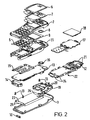
- FIG. 2 shows an exploded view of the radiotelephone of FIG. 1;
- FIG. 3 shows the inner housing of the radiotelephone of FIG. 1;
- FIG. 4 shows the first housing of the radiotelephone of FIG. 1;
- FIG. 5 shows the inner housing of the radiotelephone of FIG. 1;
- FIG. 6 shows the second housing of the radiotelephone of FIG. 1.
- FIG. 1 shows a radiotelephone 1 having a first housing 2 , otherwise referred to as a front cover, a second housing 3 , otherwise referred to as a rear cover, and an inner housing 4 . Sandwiched between the front cover 2 and inner housing 4 is a keymat 5 .
- the front cover 2 is preferably made of a resilient material, for example polyarylamid.
- the front cover 2 is releasably attachable to the upper portion of the inner housing 4 by means of a snap-on connection, while the rear cover 3 is releasably attachable to the lower portion of the inner housing 4 by means of a slidable coupling.
- a slidable coupling This will be described in detail below.
- other forms of attachment may be used, for example the front cover can be attached by means of a slidable coupling.
- FIG. 2 shows the mechanical structure of the radiotelephone 1 .
- the front cover 2 includes a bezel window 6 , which is attached to the front cover 2 by means of adhesive 7 .
- a speaker gasket 8 and LCD dust seal 9 Secured to the underside of the main cover 6 is a speaker gasket 8 and LCD dust seal 9 .
- the keymat 5 is snapped on and off the inner side of the main front cover 6 .
- the main purpose of the keymat 5 is to act as an interface between the user and the functions of the radiotelephone.
- the rear cover 3 includes a release button 10 .
- the inner housing 4 comprises an upper cover 11 and a lower cover 12 which are coupled together by means of screws 13 .
- the main circuit board 13 for providing the main functionality of the radiotelephone, a system connector 14 , a dome sheet 15 which transforms the movements of the keys into an electrical connection on the circuit board, a speaker 16 , a light guide 17 and a liquid crystal display (LCD) 18 .
- LCD liquid crystal display
- An internal antenna 19 is mounted to the outer surface of the lower cover 12 by two hooks 20 that mate with two slots 21 on the lower cover 12 .
- the lower cover 12 has a recess 22 to accommodate battery 23 .
- Located on the bottom edge of the recess 22 are two slots 24 into which are located two lugs 25 on the bottom portion of battery 23 .
- the top portion of battery 23 has a resilient element 26 that engages with a slot on the top edge of the recess 22 to secure battery 23 to inner housing 4 .
- FIG. 3 shows a top perspective view of the inner housing 4 .
- a section 27 of the side wall projects laterally outward by a constant distance and provides an area for gripping the radiotelephone 1 while the front cover 2 or rear cover 3 is being removed or attached, as described below.
- the grip area 27 on each side of the radiotelephone is sized to allow a user's finger and thumb to firmly grip the radiotelephone.
- On the narrow section of each side wall are provided two slots 28 .
- the wall elements of the front cover 2 have substantially the same contour as the upper surface of the outer wall section 27 of the inner housing 4 and are designed so that front cover 2 and inner housing 4 can be fit snugly together.
- the front cover 2 has two attachment lugs 30 on the bottom portion of the cover 2 .
- Each lug 30 has a channel 31 , as shown in FIG. 4.
- each inner wall of the front cover 2 are located two attachment lugs 32 , one lug located towards the upper region of the cover 2 the other one located in the central region of the cover 2 .
- On the upper portion of front cover is provided an attachment element 33 extending away from the rear surface.
- the attachment element 33 has two apertures 34 .
- the attachment lugs 30 are inserted into the lower channels 29 as shown in FIG. 1.
- the cover is then moved in direction A until lugs 32 abut the upper surface of the narrow section of the inner housing 4 positioned above corresponding slots 28 .
- the front cover 2 is then urged towards the inner housing 4 .
- the front cover 2 is preferably made of a resilient material, thereby allowing a user to easily urge the lugs 32 over the upper surface of the inner housing 4 allowing the front cover lugs 32 to snap fit into the corresponding slots 28 on the inner housing 4 .
- a user holds/grips the grip area 27 when attaching the front cover 2 .
- a user preferably holds/grips the grip area 27 while urging the top section of the front cover 2 away from the inner housing 4 .
- the front cover 2 is then lifted away from the inner housing 4 in direction B, as shown in FIG. 1.
- FIG. 5 shows a bottom perspective view of the inner housing 4 with battery 23 and internal antenna 19 attached.
- Each side wall of the inner housing 4 has a lug 35 projecting laterally inwards.
- the bottom portion of the inner housing 4 has a release spring 36 which projects slightly above the upper surface of the side walls.
- the rear cover 3 has a first pair of L shaped attachment lugs 37 provided on the central region of each longitudinal side of the cover and a second pair of L shaped attachment lugs 38 provided on the bottom region of each longitudinal side of the cover.
- the rear cover 3 has an aperture 39 for housing release button 10 and two attachment lugs 40 provided at the top section of the rear housing 3 .
- the user preferably holds/grips grip area 27 while the rear cover 3 is disposed adjacent to the inner housing 4 positioned such that the upper L shaped lugs 37 are longitudinally separated from lugs 35 on the inner housing 4 , as shown in FIG. 1.
- the rear cover 3 and inner housing 4 are pushed together and the rear cover 3 is slid in the direction of the rear covers longitudinal axis allowing the L shaped lugs 37 to engage the inner housing lugs 35 .
- the spring clip 36 projects within the cavity defined by the inner surface of the rear cover 3 . Thereby, once the rear cover has been attached to the inner housing the spring clip 36 prevents the rear cover 3 being slid longitudinally and consequently prevents the removal of the rear cover 3 .
- the lower L shaped lugs 38 engage with channels 31 formed in the front cover lugs 30 .
- the upper lugs 40 on the rear cover 3 engage with apertures 34 on the front cover, thereby, interlocking the front and rear covers.
- the attachment of the rear cover 3 secures the front cover 4 to the inner housing and prevents the removal of the front cover while the rear cover is attached to the inner housing.
- the radiotelephone is preferably held/gripped in grip area 27 while the release button 10 is depressed in direction C, as shown in FIG. 1, to urge the release spring clip 36 down below the level of the inner housing side walls. This allows the rear cover to be slid longitudinally away in direction D, as shown in FIG. 1.
- the first attaching means allows the first housing and the inner housing to be slidably coupled.
Abstract
An electronic radiotelephone comprising a first housing, a second housing, and an inner housing having retaining means for retaining to the inner housing the electronic components of the radiotelephone; and first releasable attaching means for releasable attaching the first housing to the inner housing, wherein the first housing, when attached to the inner housing, is presented towards a user during operation of the radiotelephone; and second releasably attaching means for releasable attaching the second housing to the inner housing, wherein the second housing, when attached to the inner housing, faces away from the user during operation of the radiotelephone.
Description
- It has become desirable for users of radiotelephones to replace a broken or scratched housing of the radiotelephone easily without requiring any special training or tools. Also, users of radiotelephones may want to change the appearance of their radiotelephone by replacing its housing with another of a different appearance. While it is known to replace a front cover of a radiotelephone this only allows a user to replace a broken or scratched front cover or change the appearance of the front of the radiotelephone, not the overall appearance.
- Typically, the front and rear housings of a radiotelephone retain the internal components of the radiotelephone. Therefore, the removal of the front and rear housings can result in the internal components of the phone becoming loose and/or exposed thereby increasing the risk of the components being damaged. Further, while the appearance of the radiotelephone battery, which is typically attached to the rear housing of the radiotelephone, can be modified to match that of the front cover the battery only covers a portion of the rear housing of the radiotelephone. Further, as a battery is a renewable item and may require to be changed separately to the front cover this would require suppliers to increase stocks of batteries to cover the range of different appearances or for a customer to wait while the battery is being manufactured and delivered.
- In accordance with a first aspect of the present invention there is provided An electronic radiotelephone comprising a first housing, a second housing, and an inner housing having retaining means for retaining to the inner housing the electronic components of the radiotelephone; and first releasably attaching means for releasably attaching the first housing to the inner housing, wherein the first housing, when attached to the inner housing, is presented towards a user during operation of the radiotelephone; and second releasably attaching means for releasably attaching the second housing to the inner housing, wherein the second housing, when attached to the inner housing, faces away from the user during operation of the radiotelephone.
- The present invention provides the advantage that a user is able to replace a broken or damaged front and rear cover or change the overall appearance of the radiotelephone without increasing the risk of the radiotelephone components being damaged and without the need for manufacture's to produce a variety of batteries of different appearance for the same type of radiotelephone.
- Preferably the inner housing has an external surface to allow a user to grip the inner housing to aid the releasing and/or attaching of the first or second housing from/to the inner housing.
- This provides the advantage that a user is able to grip the radiotelephone sufficiently to allow removal of the first and second housings. The grip area preferably comprises an area on each side of the radiotelephone sized to allow a user's finger and thumb to firmly grip the radiotelephone.
- Preferably the first attaching means includes a latching member disposed on the first housing for engagement with a complementary latching member disposed on the inner housing.
- Suitably the latching member disposed on the first housing is a lug formed on a resilient part of the first housing and the complementary latching member on the inner housing is a slot to allow the first housing to be push-fitted onto the first housing.
- Preferably the second attachment means includes a latching member disposed on the second housing for engagement with a complementary latching member disposed on the inner housing.
- Suitably the second attachment means allows the second housing and the inner housing to be slidably coupled.
- Preferably the first and second housings have interlocking means which are arranged to interlock the first and second housings when the first and second housings are attached to the inner housing. This provides extra stability to the construction of the radiotelephone.
- Preferably the second housing overlays a battery retained by the inner housing, thereby concealing the battery when the second housing is attached.
- In accordance with a second aspect of the present invention there is provided a first housing and second housing for an inner electronic radiotelephone housing having retaining means for retaining to the inner housing the electronic components of the radiotelephone, the first housing and second housing having releasable attaching means for releasable attaching to the inner housing so that the first housing is presented to a user during operation of the radiotelephone when the first housing is releasable attached to the inner housing and the second housing faces away from the user during operation of the radiotelephone when the second housing is releasable attached to the inner housing.
- In accordance with a further aspect of the present invention there is provided set of exchangeable cover parts for enclosing a radiotelephone body containing the electronic components of the radiotelephone, said set of exchangeable cover parts includes an exchangeable front cover and an exchangeable rear cover, a first one of said set of exchangeable cover parts includes first locking means in a first end of said of first cover part for engaging the a lower end of the radiophone body in order to guide said of first cover part in a pivotal movement when attached to the radiophone body, and second locking means in the end opposite to the first end for engaging the upper portion of the radiophone body by means of a snap-on connection, a second one of said set of exchangeable cover parts for being slidable coupled to the first cover part when placed on the radiophone body, said second cover part includes third locking means for in the upper end of said second cover part for engaging said second locking means of the first cover part in order to prohibit a release of said snap-on connection when the set of exchangeable cover parts are assembled with the radiophone body sandwiched in between, fourth locking means for in the lower end of said second cover part for engaging said first locking means of the first cover part in order to prohibit a release said engagement when the set of exchangeable cover parts are assembled with the radiophone body sandwiched in between, and fifth locking means for interacting with locking means on the radiophone body in order to block the slidability of the second cover part relatively to the first cover part when placed on the radiophone body, and said fifth locking means are releasably by means of a user operated release button.
- For a better understanding of the present invention and to understand how the same may be brought into effect reference will now be made, by way of example only, to accompanying drawings, in which:
- FIG. 1 shows a radiotelephone according to an embodiment of the present invention;
- FIG. 2 shows an exploded view of the radiotelephone of FIG. 1;
- FIG. 3 shows the inner housing of the radiotelephone of FIG. 1;
- FIG. 4 shows the first housing of the radiotelephone of FIG. 1;
- FIG. 5 shows the inner housing of the radiotelephone of FIG. 1;
- FIG. 6 shows the second housing of the radiotelephone of FIG. 1.
- FIG. 1 shows a radiotelephone 1 having a first housing 2, otherwise referred to as a front cover, a second housing 3, otherwise referred to as a rear cover, and an inner housing 4. Sandwiched between the front cover 2 and inner housing 4 is a
keymat 5. The front cover 2 is preferably made of a resilient material, for example polyarylamid. - In this embodiment, the front cover 2 is releasably attachable to the upper portion of the inner housing 4 by means of a snap-on connection, while the rear cover 3 is releasably attachable to the lower portion of the inner housing 4 by means of a slidable coupling. This will be described in detail below. However, other forms of attachment may be used, for example the front cover can be attached by means of a slidable coupling.
- FIG. 2 shows the mechanical structure of the radiotelephone 1. The front cover 2 includes a
bezel window 6, which is attached to the front cover 2 by means of adhesive 7. Secured to the underside of themain cover 6 is aspeaker gasket 8 andLCD dust seal 9. Thekeymat 5 is snapped on and off the inner side of themain front cover 6. The main purpose of thekeymat 5 is to act as an interface between the user and the functions of the radiotelephone. The rear cover 3 includes arelease button 10. The inner housing 4 comprises an upper cover 11 and alower cover 12 which are coupled together by means ofscrews 13. Retained between the upper cover 11 andlower cover 12 is themain circuit board 13 for providing the main functionality of the radiotelephone, asystem connector 14 , adome sheet 15 which transforms the movements of the keys into an electrical connection on the circuit board, aspeaker 16, alight guide 17 and a liquid crystal display (LCD) 18. - An
internal antenna 19 is mounted to the outer surface of thelower cover 12 by twohooks 20 that mate with twoslots 21 on thelower cover 12. - The
lower cover 12 has arecess 22 to accommodatebattery 23. Located on the bottom edge of therecess 22 are twoslots 24 into which are located twolugs 25 on the bottom portion ofbattery 23. The top portion ofbattery 23 has aresilient element 26 that engages with a slot on the top edge of therecess 22 to securebattery 23 to inner housing 4. - FIG. 3 shows a top perspective view of the inner housing 4. A
section 27 of the side wall projects laterally outward by a constant distance and provides an area for gripping the radiotelephone 1 while the front cover 2 or rear cover 3 is being removed or attached, as described below. Thegrip area 27 on each side of the radiotelephone is sized to allow a user's finger and thumb to firmly grip the radiotelephone. On the narrow section of each side wall are provided twoslots 28. - On the bottom portion of the inner housing 4 are provided two
channels 29 that extend through the inner housing 4 from the upper cover 11 through thelower cover 12. - The wall elements of the front cover 2 have substantially the same contour as the upper surface of the
outer wall section 27 of the inner housing 4 and are designed so that front cover 2 and inner housing 4 can be fit snugly together. - The front cover 2 has two
attachment lugs 30 on the bottom portion of the cover 2. Eachlug 30 has achannel 31, as shown in FIG. 4. - On each inner wall of the front cover 2 are located two
attachment lugs 32, one lug located towards the upper region of the cover 2 the other one located in the central region of the cover 2. On the upper portion of front cover is provided anattachment element 33 extending away from the rear surface. Theattachment element 33 has twoapertures 34. - To attach the front cover 2 to the inner housing 4 the
attachment lugs 30 are inserted into thelower channels 29 as shown in FIG. 1. The cover is then moved in direction A untillugs 32 abut the upper surface of the narrow section of the inner housing 4 positioned abovecorresponding slots 28. The front cover 2 is then urged towards the inner housing 4. The front cover 2 is preferably made of a resilient material, thereby allowing a user to easily urge thelugs 32 over the upper surface of the inner housing 4 allowing thefront cover lugs 32 to snap fit into thecorresponding slots 28 on the inner housing 4. Preferably a user holds/grips thegrip area 27 when attaching the front cover 2. To remove the front cover 2 from the inner housing 4 a user preferably holds/grips thegrip area 27 while urging the top section of the front cover 2 away from the inner housing 4. The front cover 2 is then lifted away from the inner housing 4 in direction B, as shown in FIG. 1. - FIG. 5 shows a bottom perspective view of the inner housing 4 with
battery 23 andinternal antenna 19 attached. Each side wall of the inner housing 4 has alug 35 projecting laterally inwards. The bottom portion of the inner housing 4 has arelease spring 36 which projects slightly above the upper surface of the side walls. - As shown in FIG. 6, the rear cover 3 has a first pair of L shaped attachment lugs 37 provided on the central region of each longitudinal side of the cover and a second pair of L shaped attachment lugs 38 provided on the bottom region of each longitudinal side of the cover. In addition, the rear cover 3 has an
aperture 39 forhousing release button 10 and two attachment lugs 40 provided at the top section of the rear housing 3. - To attach rear cover 3 to the inner housing 4 the user preferably holds/grips
grip area 27 while the rear cover 3 is disposed adjacent to the inner housing 4 positioned such that the upper L shaped lugs 37 are longitudinally separated fromlugs 35 on the inner housing 4, as shown in FIG. 1. The rear cover 3 and inner housing 4 are pushed together and the rear cover 3 is slid in the direction of the rear covers longitudinal axis allowing the L shaped lugs 37 to engage the inner housing lugs 35. When the rear cover 3 is attached to the inner housing 4 thespring clip 36 projects within the cavity defined by the inner surface of the rear cover 3. Thereby, once the rear cover has been attached to the inner housing thespring clip 36 prevents the rear cover 3 being slid longitudinally and consequently prevents the removal of the rear cover 3. - If the rear cover 3 is attached to the inner housing 4 when front cover 2 has already been attached the lower L shaped lugs 38 engage with
channels 31 formed in the front cover lugs 30. Further, the upper lugs 40 on the rear cover 3 engage withapertures 34 on the front cover, thereby, interlocking the front and rear covers. Thus, the attachment of the rear cover 3 secures the front cover 4 to the inner housing and prevents the removal of the front cover while the rear cover is attached to the inner housing. - To remove the rear cover the radiotelephone is preferably held/gripped in
grip area 27 while therelease button 10 is depressed in direction C, as shown in FIG. 1, to urge therelease spring clip 36 down below the level of the inner housing side walls. This allows the rear cover to be slid longitudinally away in direction D, as shown in FIG. 1. - In view of the foregoing description, it will be evident to a person skilled in the art that various modifications may be made within the scope of the claims. For example the first attaching means allows the first housing and the inner housing to be slidably coupled.
Claims (12)
1. An electronic radiotelephone comprising a first housing, a second housing, and an inner housing having retaining means for retaining to the inner housing the electronic components of the radiotelephone; and first releasable attaching means for releasable attaching the first housing to the inner housing, wherein the first housing, when attached to the inner housing, is presented towards a user during operation of the radiotelephone; and second releasable attaching means for releasably attaching the second housing to the inner housing, wherein the second housing, when attached to the inner housing, faces away from the user during operation of the radiotelephone.
2. A radiotelephone according to claim 1 , wherein the inner housing has an external surface to allow a user to grip the inner housing to aid the releasing and/or attaching of the first or second housing from/to the inner housing.
3. A radiotelephone according to claim 1 , wherein the first attaching means includes a latching member disposed on the first housing for engagement with a complementary latching member disposed on the inner housing.
4. A radiotelephone according to claim 3 , wherein the latching member disposed on the first housing is a lug formed on a resilient part of the first housing and the complementary latching member on the inner housing is a slot to allow the first housing to be push-fitted onto the first housing.
5. A radiotelephone according to claim 1 , wherein the second attaching means includes a latching member disposed on the second housing for engagement with a complementary latching member disposed on the inner housing.
6. A radiotelephone according to claim 5 , wherein the second attaching means allows the second housing and the inner housing to be slidably coupled.
7. A radiotelephone according to claim 1 , wherein the first and second housings have interlocking means which are arranged to interlock the first and second housings when the first and second housings are attached to the inner housing.
8. A radiotelephone according to claim 1 , wherein the first housing has a user interface, which in use, co-operates with the inner housing to operate the radiotelephone.
9. A radiotelephone according to claim 1 , further comprising a key mat mounted within the first housing, which in use, co-operates with the inner housing to operate the radiotelephone.
10. A radiotelephone according to claim 1 , wherein the second housing overlays a battery retained by the inner housing.
11. A first housing and second housing for an inner electronic radiotelephone housing having retaining means for retaining to the inner housing the electronic components of the radiotelephone, the first housing and second housing having releasable attaching means for releasable attaching to the inner housing so that the first housing is presented to a user during operation of the radiotelephone when the first housing is releasable attached to the inner housing and the second housing faces away from the user during operation of the radiotelephone when the second housing is releasable attached to the inner housing.
12. A set of exchangeable cover parts for enclosing a radiotelephone body containing the electronic components of the radiotelephone,
said set of exchangeable cover parts includes an exchangeable front cover and an exchangeable rear cover, a first one of said set of exchangeable cover parts includes:
first locking means in a first end of said of first cover part for engaging the a lower end of the radiophone body in order to guide said of first cover part in a pivotal movement when attached to the radiophone body, and
second locking means in the end opposite to the first end for engaging the upper portion of the radiophone body by means of a snap-on connection
a second one of said set of exchangeable cover parts for being slidable coupled to the first cover part when placed on the radiophone body, said second cover part includes:
third locking means for in the upper end of said second cover part for engaging said second locking means of the first cover part in order to prohibit a release of said snap-on connection when the set of exchangeable cover parts are assembled with the radiophone body sandwiched in between,
fourth locking means for in the lower end of said second cover part for engaging said first locking means of the first cover part in order to prohibit a release said engagement when the set of exchangeable cover parts are assembled with the radiophone body sandwiched in between, and
fifth locking means for interacting with locking means on the radiophone body in order to block the slidability of the second cover part relatively to the first cover part when placed on the radiophone body, and said fifth locking means are releasably by means of a user operated release button.
Priority Applications (1)
| Application Number | Priority Date | Filing Date | Title |
|---|---|---|---|
| US10/447,643 US6847806B2 (en) | 1999-02-12 | 2003-05-29 | Radiotelephone |
Applications Claiming Priority (4)
| Application Number | Priority Date | Filing Date | Title |
|---|---|---|---|
| GB9903260A GB2346759B (en) | 1999-02-12 | 1999-02-12 | Radiotelephone |
| GB9903260.9 | 1999-12-02 | ||
| US09/503,595 US6594472B1 (en) | 1999-02-12 | 2000-02-11 | Exchangeable radiotelephone covers |
| US10/447,643 US6847806B2 (en) | 1999-02-12 | 2003-05-29 | Radiotelephone |
Related Parent Applications (1)
| Application Number | Title | Priority Date | Filing Date |
|---|---|---|---|
| US09/503,595 Division US6594472B1 (en) | 1999-02-12 | 2000-02-11 | Exchangeable radiotelephone covers |
Publications (2)
| Publication Number | Publication Date |
|---|---|
| US20030194974A1 true US20030194974A1 (en) | 2003-10-16 |
| US6847806B2 US6847806B2 (en) | 2005-01-25 |
Family
ID=10847688
Family Applications (2)
| Application Number | Title | Priority Date | Filing Date |
|---|---|---|---|
| US09/503,595 Expired - Lifetime US6594472B1 (en) | 1999-02-12 | 2000-02-11 | Exchangeable radiotelephone covers |
| US10/447,643 Expired - Lifetime US6847806B2 (en) | 1999-02-12 | 2003-05-29 | Radiotelephone |
Family Applications Before (1)
| Application Number | Title | Priority Date | Filing Date |
|---|---|---|---|
| US09/503,595 Expired - Lifetime US6594472B1 (en) | 1999-02-12 | 2000-02-11 | Exchangeable radiotelephone covers |
Country Status (9)
| Country | Link |
|---|---|
| US (2) | US6594472B1 (en) |
| EP (2) | EP1028574B1 (en) |
| AT (2) | ATE341148T1 (en) |
| DE (3) | DE60004415T2 (en) |
| DK (2) | DK1028574T3 (en) |
| ES (2) | ES2271425T3 (en) |
| FI (1) | FI4497U1 (en) |
| GB (1) | GB2346759B (en) |
| PT (1) | PT1028574E (en) |
Cited By (11)
| Publication number | Priority date | Publication date | Assignee | Title |
|---|---|---|---|---|
| US20030083019A1 (en) * | 2001-10-31 | 2003-05-01 | Wong John Patrick | Lightweight mobile station |
| US20040092283A1 (en) * | 2000-12-29 | 2004-05-13 | Mark Hutchison | Casting for portable communication device |
| US20040095500A1 (en) * | 2001-03-19 | 2004-05-20 | Takeshi Sato | Mobile terminal device having camera function |
| US20050215292A1 (en) * | 2004-03-24 | 2005-09-29 | Kazunori Imazaki | Portable electronic device and carrier telephone equipment |
| US20060037807A1 (en) * | 2004-08-18 | 2006-02-23 | Fujitsu Limited | Portable terminal apparatus |
| US20060135056A1 (en) * | 2002-07-12 | 2006-06-22 | Ake Rydgren | Radio communication terminal with a detachable active housing and related connector |
| US20100053863A1 (en) * | 2006-04-27 | 2010-03-04 | Research In Motion Limited | Handheld electronic device having hidden sound openings offset from an audio source |
| US20120081865A1 (en) * | 2010-09-30 | 2012-04-05 | Fih (Hong Kong) Limited | Dustproof structure and electronic device employing the same |
| US20120275095A1 (en) * | 2011-04-29 | 2012-11-01 | Hon Hai Precision Industry Co., Ltd. | Portable electonic device |
| US20130040709A1 (en) * | 2009-11-10 | 2013-02-14 | At&T Mobility Ii Llc | Devices, Systems and Methods for Identification Through a Mobile Device |
| CN104350729A (en) * | 2012-03-30 | 2015-02-11 | 橙公司 | Shell for mobile telephone and mobile terminal |
Families Citing this family (124)
| Publication number | Priority date | Publication date | Assignee | Title |
|---|---|---|---|---|
| US7092520B2 (en) * | 1996-02-28 | 2006-08-15 | Nokia Corporation | Radiotelephone |
| EP1852836A3 (en) * | 1999-05-26 | 2011-03-30 | Johnson Controls Technology Company | Wireless communications system and method |
| US7346374B2 (en) | 1999-05-26 | 2008-03-18 | Johnson Controls Technology Company | Wireless communications system and method |
| DE10003699A1 (en) * | 2000-01-28 | 2001-08-09 | Siemens Ag | Keypad-operated e.g. mobile telephone with user-replaceable casing, includes support covered by protective sheet integrating improved tactility |
| GB2362774B (en) | 2000-05-26 | 2004-08-18 | Nokia Mobile Phones Ltd | Radiotelephone |
| KR200211455Y1 (en) * | 2000-08-08 | 2001-01-15 | 엘지정보통신주식회사 | Mobile station |
| GB2366453A (en) | 2000-08-31 | 2002-03-06 | Nokia Mobile Phones Ltd | An antenna device for a communication terminal |
| US7194291B2 (en) * | 2001-06-26 | 2007-03-20 | Gregory Kim | Protective mask of mobile phone |
| US20040053650A1 (en) * | 2000-11-18 | 2004-03-18 | Roper Michael John | Configurable mobile telephone |
| US20020065054A1 (en) * | 2000-11-29 | 2002-05-30 | Morris Humphreys | Mobile station and elastomeric cover |
| GB2369741B (en) * | 2000-11-30 | 2004-11-17 | Matsushita Comm Ind Uk Ltd | Removable covers for a mobile telephone |
| GB2374235B (en) * | 2000-12-29 | 2004-09-22 | Nokia Mobile Phones Ltd | A casing |
| GB2373953B (en) * | 2000-12-29 | 2004-10-06 | Nokia Mobile Phones Ltd | A casing |
| GB2377115B (en) * | 2000-12-29 | 2005-06-22 | Nokia Mobile Phones Ltd | A casing for a personal communication device, comprising precious metals, precious stones or ceramics |
| US7375973B2 (en) | 2000-12-29 | 2008-05-20 | Vertu Limited | Casing for a communication device |
| GB2373394A (en) * | 2000-12-29 | 2002-09-18 | Nokia Mobile Phones Ltd | Customised casings for electronic devices |
| JP2004517447A (en) * | 2000-12-29 | 2004-06-10 | ベルツ リミテッド | Case |
| US7418282B2 (en) | 2000-12-29 | 2008-08-26 | Vertu Limited | Casing for portable communication device |
| GB2373397A (en) * | 2000-12-29 | 2002-09-18 | Nokia Mobile Phones Ltd | Customised casings for electronic devices and methods of commissioning therefor |
| GB2373954B (en) * | 2000-12-29 | 2005-06-29 | Nokia Mobile Phones Ltd | A casing |
| US7830671B2 (en) | 2000-12-29 | 2010-11-09 | Vertu Limited | Casing |
| GB2373952B (en) * | 2000-12-29 | 2004-10-27 | Nokia Mobile Phones Ltd | A casing |
| US7693557B2 (en) | 2000-12-29 | 2010-04-06 | Nokia Corporation | Method of producing a telephone device |
| US7454014B2 (en) | 2000-12-29 | 2008-11-18 | Vertu Limited | Device with a loudspeaker and an ear piece cover |
| GB0104151D0 (en) * | 2001-02-20 | 2001-04-11 | Sendo Int Ltd | Telephone apparatus |
| JP2002290065A (en) * | 2001-03-27 | 2002-10-04 | Toshiba Corp | Mobile communication terminal device |
| DE10118715A1 (en) * | 2001-04-12 | 2002-10-17 | Andreas Peiker | handset |
| US20030104791A1 (en) * | 2001-05-17 | 2003-06-05 | Engstrom G. Eric | Adding peripherals to mobile device via smart interchangeable cover |
| US7069063B2 (en) * | 2001-06-19 | 2006-06-27 | Nokia Mobile Phones Limited | User changeable mobile phone cover |
| KR100663459B1 (en) * | 2001-07-07 | 2007-01-02 | 삼성전자주식회사 | Replaceable sliding covering unit for folder in folder-type portable radiotelephone |
| US7095986B2 (en) * | 2001-07-17 | 2006-08-22 | Wildseed Ltd. | Interchangeable covering with keys for personalizing mobile electronic communication devices |
| US6950516B2 (en) * | 2001-10-05 | 2005-09-27 | Nokia Corporation | User changeable electronic device/mobile phone covers and method |
| US7609512B2 (en) | 2001-11-19 | 2009-10-27 | Otter Products, Llc | Protective enclosure for electronic device |
| KR100454969B1 (en) | 2001-11-27 | 2004-11-06 | 삼성전자주식회사 | Exterior-replacable sub-housing and flip-type/bar-type combination mobile phone therewith |
| KR100495116B1 (en) * | 2001-12-13 | 2005-06-14 | 주식회사 팬택 | Portable Terminal Having Changeable Front Case |
| US7206618B2 (en) * | 2002-01-11 | 2007-04-17 | Intel Corporation | Removable customizable inserts and faceplate for electronic devices |
| FR2835379B1 (en) * | 2002-01-25 | 2004-03-12 | Sagem | MOBILE PHONE HOUSING WITH REMOVABLE COVER |
| FI5838U1 (en) | 2002-03-08 | 2003-06-30 | Nokia Corp | Shell |
| TW582679U (en) * | 2002-05-13 | 2004-04-01 | Quanta Comp Inc | Mobile phone |
| TW586733U (en) * | 2002-07-31 | 2004-05-01 | Benq Corp | Mechanical structure used in electronic device with interchangeable housing |
| US20040097276A1 (en) * | 2002-11-14 | 2004-05-20 | Harmon Roger Wright | Replaceable housing for a mobile communication device |
| US7203467B2 (en) * | 2003-04-14 | 2007-04-10 | Microsoft Corporation | Protective case for electronics in a mobile device |
| US20040242288A1 (en) * | 2003-05-29 | 2004-12-02 | Henrik Balle | Portable communication apparatus, a rotary input device having an end-user-exchangeable element, and an end-user-exchangeable element for a rotary input device |
| TWI271085B (en) * | 2003-06-19 | 2007-01-11 | Benq Corp | Housing fabricating movement |
| US20040263359A1 (en) * | 2003-06-27 | 2004-12-30 | Hampton Patrick A. | Transducer assembly |
| AU2003277861A1 (en) * | 2003-09-16 | 2005-04-06 | Nokia Corporation | User attachable keypad |
| AU2004307045A1 (en) * | 2003-10-14 | 2005-04-28 | Sentinel Gardens Pty Ltd | Protective shroud |
| US7236588B2 (en) * | 2003-12-12 | 2007-06-26 | Nokia Corporation | Interlocking cover for mobile terminals |
| US7844309B2 (en) | 2004-02-27 | 2010-11-30 | Nokia Corporation | Exchangeable keymat |
| US7409058B2 (en) | 2004-06-01 | 2008-08-05 | Research In Motion Limited | Display cover for a communication device |
| US20060040081A1 (en) * | 2004-08-23 | 2006-02-23 | Hodsdon Jerry G | Apparatus, system, and method for personalizing a portable electronic device |
| JP3966320B2 (en) * | 2004-09-28 | 2007-08-29 | セイコーエプソン株式会社 | Electro-optical device and electronic apparatus |
| CN2777908Y (en) * | 2004-12-30 | 2006-05-03 | 深圳富泰宏精密工业有限公司 | Cell cover structure for portable electronic apparatus |
| US8073131B2 (en) * | 2005-01-03 | 2011-12-06 | Fellowes, Inc. | Portable device case with corner protector |
| GB2439849B (en) | 2005-01-03 | 2008-07-30 | Fellowes Inc | Removable mounting post assembly for a carrying case |
| KR100630193B1 (en) * | 2005-03-14 | 2006-09-29 | 삼성전자주식회사 | Sliding module for portable terminal |
| US20060211498A1 (en) * | 2005-03-18 | 2006-09-21 | Vincent Higgins | Information display faceplate for a video game controller |
| US7914869B2 (en) * | 2005-04-18 | 2011-03-29 | Avery Dennison Corporation | Mobile device label with negative image feature |
| US20070021156A1 (en) * | 2005-07-19 | 2007-01-25 | Hoong Chow T | Compact radio communications device |
| US20070223744A1 (en) * | 2006-03-23 | 2007-09-27 | Epson Imaging Devices Corporation | Electro-optic device and electronic apparatus |
| US7787618B2 (en) | 2006-03-29 | 2010-08-31 | Nokia Corporation | Portable electronic device |
| US20070241021A1 (en) * | 2006-04-12 | 2007-10-18 | Nokia Corporation | Thermoformed cover for electronic device and method for forming |
| US20070293282A1 (en) * | 2006-06-14 | 2007-12-20 | Nokia Corporation | Metal cover assembly |
| US7733659B2 (en) * | 2006-08-18 | 2010-06-08 | Delphi Technologies, Inc. | Lightweight audio system for automotive applications and method |
| KR101020464B1 (en) * | 2006-08-25 | 2011-03-08 | 교세라 가부시키가이샤 | Electronic device |
| US7818034B2 (en) * | 2007-03-30 | 2010-10-19 | Motorola, Inc. | Multi-mode pivoting carrying holder for mobile devices |
| US7829786B2 (en) * | 2007-09-18 | 2010-11-09 | Motorola, Inc. | Sealing system and method for sealing a component within an electronic device |
| JP4538483B2 (en) | 2007-10-23 | 2010-09-08 | 株式会社カシオ日立モバイルコミュニケーションズ | Waterproof structure and electronic equipment |
| US8004835B2 (en) * | 2007-12-27 | 2011-08-23 | Hand Held Products, Inc. | Portable data terminal internal support structure |
| US8367235B2 (en) | 2008-01-18 | 2013-02-05 | Mophie, Inc. | Battery pack, holster, and extendible processing and interface platform for mobile devices |
| US20090205983A1 (en) * | 2008-02-19 | 2009-08-20 | Sony Ericsson Mobile Communications Ab | Metal cover for portable electronic device |
| US7933123B2 (en) | 2008-04-11 | 2011-04-26 | Apple Inc. | Portable electronic device with two-piece housing |
| NZ589503A (en) * | 2008-05-07 | 2013-07-26 | Signostics Ltd | Docking system for medical diagnostic scanning using a handheld device |
| US7782610B2 (en) | 2008-11-17 | 2010-08-24 | Incase Designs Corp. | Portable electronic device case with battery |
| US8284558B2 (en) * | 2008-12-15 | 2012-10-09 | Nokia Corporation | Apparatus and method for use in assembly of a portable apparatus |
| US9055142B2 (en) | 2008-12-15 | 2015-06-09 | Nokia Technologies Oy | Apparatus and method for use in assembly of a portable apparatus |
| WO2010078321A1 (en) | 2008-12-29 | 2010-07-08 | Otter Products, Llc | Protective cushion cover for an electronic device |
| US9007747B2 (en) * | 2009-05-29 | 2015-04-14 | Fellowes, Inc. | Slider case for portable electronic device |
| US8965458B2 (en) | 2009-08-21 | 2015-02-24 | Otter Products, Llc | Protective cushion cover for an electronic device |
| KR101613928B1 (en) | 2009-09-09 | 2016-04-20 | 엘지전자 주식회사 | Portable terminal |
| US9025317B2 (en) | 2010-03-17 | 2015-05-05 | Otter Products, Llc | Multi-material protective case for sliding/articulating/rotating handheld electronic devices |
| CN102223772B (en) * | 2010-04-14 | 2014-03-05 | 深圳富泰宏精密工业有限公司 | Composite shell and electronic device applying same |
| WO2011146784A1 (en) | 2010-05-19 | 2011-11-24 | Mophie, Inc. | Credit card reader for mobile device |
| US8289702B2 (en) * | 2010-08-11 | 2012-10-16 | Sihar Ahmad Karwan | Universal rearward keyboard with means for inserting a portable computational display |
| US9549598B2 (en) | 2010-10-12 | 2017-01-24 | Treefrog Developments, Inc. | Housing for encasing an electronic device |
| US8342325B2 (en) | 2010-10-12 | 2013-01-01 | Treefrog Developments, Inc | Housing for receiving and encasing an object |
| WO2012170964A2 (en) | 2011-06-10 | 2012-12-13 | Mophie, Inc. | Wireless communication accessory for a mobile device |
| WO2012174175A2 (en) | 2011-06-13 | 2012-12-20 | Tree Frog Developments, Inc. | Housing for encasing a tablet computer |
| USD736777S1 (en) | 2012-06-13 | 2015-08-18 | Treefrog Developments, Inc. | Case for an electronic device |
| US9615476B2 (en) | 2011-06-13 | 2017-04-04 | Treefrog Developments, Inc. | Housing for encasing a mobile device |
| US8929065B2 (en) * | 2011-08-23 | 2015-01-06 | L&P Property Management Company | Docking station with ruggedized case |
| MX345636B (en) | 2011-12-22 | 2017-02-08 | Treefrog Dev Inc | Accessories for use with housing for an electronic device. |
| WO2013106474A1 (en) | 2012-01-10 | 2013-07-18 | The Joy Factory, Inc. | Protective casing providing impact absorption and water resistance for portable electronic devices |
| KR101929879B1 (en) * | 2012-04-09 | 2019-03-15 | 삼성전자주식회사 | Portable terminal |
| US9469469B2 (en) | 2012-06-01 | 2016-10-18 | Treefrog Developments, Inc. | Housing for encasing an object having a thin profile |
| CN103491734A (en) * | 2012-06-11 | 2014-01-01 | 深圳富泰宏精密工业有限公司 | Lock-holding structure and electronic device using same |
| US9241551B2 (en) | 2012-06-13 | 2016-01-26 | Otter Products, Llc | Protective case with compartment |
| US8675359B2 (en) * | 2012-08-01 | 2014-03-18 | Tsan-Nien Chen | Protective cover structure |
| US9755444B2 (en) | 2013-02-25 | 2017-09-05 | Mophie, Inc. | Protective case with switch cover |
| WO2014150555A1 (en) * | 2013-03-15 | 2014-09-25 | Mophie, Inc. | Protective case for mobile device |
| JP5920271B2 (en) * | 2013-03-28 | 2016-05-18 | ブラザー工業株式会社 | Storage container |
| EP2996513B1 (en) | 2013-05-18 | 2018-03-28 | Otter Products, LLC | Waterproof protective case for an electronic device |
| DE102014100154A1 (en) * | 2013-05-29 | 2014-12-04 | Huf Hülsbeck & Fürst Gmbh & Co. Kg | Electronic key |
| US9300078B2 (en) | 2013-08-23 | 2016-03-29 | Otter Products, Llc | Waterproof housing for mobile electronic device and waterproof adapter for accessory device |
| US9495375B2 (en) | 2013-11-27 | 2016-11-15 | Mophie, Inc. | Battery pack with supplemental memory |
| US9277306B2 (en) * | 2013-12-27 | 2016-03-01 | Intel Corporation | Integrated speaker enclosures for electronic devices |
| DE102014004426A1 (en) * | 2014-03-25 | 2015-10-01 | Novoferm Tormatic Gmbh | transmitter |
| US9997933B2 (en) | 2014-09-03 | 2018-06-12 | Mophie, Inc. | Systems and methods for battery charging and management |
| USD797092S1 (en) | 2014-11-25 | 2017-09-12 | Mophie, Inc. | Case for a mobile electronic device |
| USD797091S1 (en) | 2014-11-25 | 2017-09-12 | Mophie, Inc. | Case for a mobile electronic device |
| USD797093S1 (en) | 2014-12-03 | 2017-09-12 | Mophie, Inc. | Case for a mobile electronic device |
| US9356267B1 (en) | 2014-12-17 | 2016-05-31 | Mophie, Inc. | Protective battery case to partially enclose a mobile electronic device |
| USD766819S1 (en) | 2015-04-06 | 2016-09-20 | Mophie, Inc. | Protective battery case |
| US9577697B2 (en) | 2015-05-27 | 2017-02-21 | Otter Products, Llc | Protective case with stylus access feature |
| USD861653S1 (en) | 2015-05-27 | 2019-10-01 | Mophie Inc. | Protective battery case for mobile communications device |
| JP6365558B2 (en) * | 2016-01-27 | 2018-08-01 | ブラザー工業株式会社 | Printing device |
| US9960521B2 (en) | 2016-02-24 | 2018-05-01 | Otter Products, Llc | Connector for fluidly sealing an aperture of a protective case |
| USD950538S1 (en) * | 2016-03-03 | 2022-05-03 | Mophie Inc. | Case for a mobile electronic device |
| US9924769B1 (en) * | 2016-03-08 | 2018-03-27 | Spigen Korea Co., Ltd. | Case for electronic device with upper and lower housings |
| US10159320B2 (en) | 2016-09-07 | 2018-12-25 | Otter Products, Llc | Protective enclosure for encasing an electronic device |
| US10516431B2 (en) | 2017-11-21 | 2019-12-24 | Mophie Inc. | Mobile device case for receiving wireless signals |
| US10362217B1 (en) * | 2018-01-05 | 2019-07-23 | Shenzhen Fengxian Investment Development Co., Ltd. | Device for operating touch screen underwater |
| US10827809B2 (en) | 2018-04-05 | 2020-11-10 | Otter Products, Llc | Protective case for electronic device |
| US10615836B1 (en) | 2018-12-20 | 2020-04-07 | Motorola Solutions, Inc. | Radio with customizable external housing |
Citations (12)
| Publication number | Priority date | Publication date | Assignee | Title |
|---|---|---|---|---|
| US5335273A (en) * | 1990-09-07 | 1994-08-02 | Fujitsu Limited | Portable telephone and multifunctional protective housing therefor |
| US5493690A (en) * | 1993-06-28 | 1996-02-20 | Nec Corporation | Foldable portable telephone set |
| US5548824A (en) * | 1993-08-25 | 1996-08-20 | Mitsubishi Denki Kabushiki Kaisha | Portable radio communication device housing having a battery storage unit |
| US5604050A (en) * | 1995-06-13 | 1997-02-18 | Motorola Inc. | Latching mechanism and method of latching thereby |
| US5659888A (en) * | 1992-05-01 | 1997-08-19 | Kabushiki Kaisha Toshiba | Radio telecommunication apparatus |
| US5706332A (en) * | 1994-09-22 | 1998-01-06 | Nec Corporation | Apparatus for unfolding and activating a portable telephone |
| US5745566A (en) * | 1996-10-15 | 1998-04-28 | Motorola, Inc. | Portable communication device having removable escutcheon elements |
| US5933330A (en) * | 1998-05-14 | 1999-08-03 | Motorola, Inc. | Portable radiotelephone arrangement having a battery pack and a detachable battery |
| US5982881A (en) * | 1995-09-26 | 1999-11-09 | Mischenko; Nicholas | Radiotelephone handset having a faceplate to accommodate a plurality of distinctive telephone appearances |
| US6151486A (en) * | 1998-10-30 | 2000-11-21 | Ericsson Inc. | Magnetic latch and release device and radiotelephones incorporating same |
| US6463262B1 (en) * | 1998-08-04 | 2002-10-08 | Nokia Mobile Phones Limited | Radio telephone |
| US6487397B2 (en) * | 1996-02-28 | 2002-11-26 | Nokia Mobile Phones Ltd. | Electronic device with housing supplement |
Family Cites Families (12)
| Publication number | Priority date | Publication date | Assignee | Title |
|---|---|---|---|---|
| JPH07250138A (en) * | 1994-03-09 | 1995-09-26 | Fujitsu Ltd | Portable radio terminal device |
| TW275174B (en) * | 1994-09-20 | 1996-05-01 | Motorola Inc | |
| SG70987A1 (en) * | 1995-05-09 | 2000-03-21 | Motorola Inc | Method and apparatus for routing conductors |
| US5848152A (en) * | 1995-09-26 | 1998-12-08 | Motorola, Inc. | Communication device having interchangeable faceplates and active keypad cover |
| EP0827662A1 (en) * | 1996-03-20 | 1998-03-11 | Koninklijke Philips Electronics N.V. | Apparatus having different shielding covers |
| US6073027A (en) * | 1996-08-29 | 2000-06-06 | Bellsouth Corporation | Portable radiotelephone with sliding cover and automatic antenna extension |
| JP3700887B2 (en) * | 1996-12-24 | 2005-09-28 | ソニー株式会社 | Storage case and terminal system |
| US5987311A (en) * | 1996-12-27 | 1999-11-16 | Ericsson Inc. | Apparatus for enabling a keypad in response to antenna extension |
| JP3098455B2 (en) * | 1997-05-14 | 2000-10-16 | 邦彦 小池 | Mobile phone |
| JP4237834B2 (en) * | 1997-06-03 | 2009-03-11 | 富士通株式会社 | Mobile phone |
| US6011699A (en) * | 1997-10-15 | 2000-01-04 | Motorola, Inc. | Electronic device including apparatus and method for routing flexible circuit conductors |
| US6006118A (en) * | 1997-12-05 | 1999-12-21 | Ericsson Inc. | Keypad lightguides including compartments |
-
1999
- 1999-02-12 GB GB9903260A patent/GB2346759B/en not_active Expired - Lifetime
-
2000
- 2000-01-28 PT PT00300698T patent/PT1028574E/en unknown
- 2000-01-28 EP EP00300698A patent/EP1028574B1/en not_active Expired - Lifetime
- 2000-01-28 DE DE60004415T patent/DE60004415T2/en not_active Expired - Lifetime
- 2000-01-28 AT AT03013237T patent/ATE341148T1/en not_active IP Right Cessation
- 2000-01-28 DE DE60031008T patent/DE60031008T2/en not_active Expired - Lifetime
- 2000-01-28 DK DK00300698T patent/DK1028574T3/en active
- 2000-01-28 ES ES03013237T patent/ES2271425T3/en not_active Expired - Lifetime
- 2000-01-28 EP EP03013237A patent/EP1367802B1/en not_active Expired - Lifetime
- 2000-01-28 ES ES00300698T patent/ES2204454T3/en not_active Expired - Lifetime
- 2000-01-28 AT AT00300698T patent/ATE247351T1/en active
- 2000-02-11 FI FI20000064U patent/FI4497U1/en active
- 2000-02-11 US US09/503,595 patent/US6594472B1/en not_active Expired - Lifetime
- 2000-02-11 DK DK200000056U patent/DK200000056Y4/en not_active IP Right Cessation
- 2000-02-11 DE DE20002445U patent/DE20002445U1/en not_active Expired - Lifetime
-
2003
- 2003-05-29 US US10/447,643 patent/US6847806B2/en not_active Expired - Lifetime
Patent Citations (12)
| Publication number | Priority date | Publication date | Assignee | Title |
|---|---|---|---|---|
| US5335273A (en) * | 1990-09-07 | 1994-08-02 | Fujitsu Limited | Portable telephone and multifunctional protective housing therefor |
| US5659888A (en) * | 1992-05-01 | 1997-08-19 | Kabushiki Kaisha Toshiba | Radio telecommunication apparatus |
| US5493690A (en) * | 1993-06-28 | 1996-02-20 | Nec Corporation | Foldable portable telephone set |
| US5548824A (en) * | 1993-08-25 | 1996-08-20 | Mitsubishi Denki Kabushiki Kaisha | Portable radio communication device housing having a battery storage unit |
| US5706332A (en) * | 1994-09-22 | 1998-01-06 | Nec Corporation | Apparatus for unfolding and activating a portable telephone |
| US5604050A (en) * | 1995-06-13 | 1997-02-18 | Motorola Inc. | Latching mechanism and method of latching thereby |
| US5982881A (en) * | 1995-09-26 | 1999-11-09 | Mischenko; Nicholas | Radiotelephone handset having a faceplate to accommodate a plurality of distinctive telephone appearances |
| US6487397B2 (en) * | 1996-02-28 | 2002-11-26 | Nokia Mobile Phones Ltd. | Electronic device with housing supplement |
| US5745566A (en) * | 1996-10-15 | 1998-04-28 | Motorola, Inc. | Portable communication device having removable escutcheon elements |
| US5933330A (en) * | 1998-05-14 | 1999-08-03 | Motorola, Inc. | Portable radiotelephone arrangement having a battery pack and a detachable battery |
| US6463262B1 (en) * | 1998-08-04 | 2002-10-08 | Nokia Mobile Phones Limited | Radio telephone |
| US6151486A (en) * | 1998-10-30 | 2000-11-21 | Ericsson Inc. | Magnetic latch and release device and radiotelephones incorporating same |
Cited By (21)
| Publication number | Priority date | Publication date | Assignee | Title |
|---|---|---|---|---|
| US20040092283A1 (en) * | 2000-12-29 | 2004-05-13 | Mark Hutchison | Casting for portable communication device |
| US7315749B2 (en) * | 2000-12-29 | 2008-01-01 | Vertu Limited | Casting for portable communication device |
| US20040095500A1 (en) * | 2001-03-19 | 2004-05-20 | Takeshi Sato | Mobile terminal device having camera function |
| US20030083019A1 (en) * | 2001-10-31 | 2003-05-01 | Wong John Patrick | Lightweight mobile station |
| US20060135056A1 (en) * | 2002-07-12 | 2006-06-22 | Ake Rydgren | Radio communication terminal with a detachable active housing and related connector |
| US7555320B2 (en) * | 2002-07-12 | 2009-06-30 | Sony Ericsson Mobile Communications Ab | Radio communication terminal with a detachable active housing and related connector |
| US20050215292A1 (en) * | 2004-03-24 | 2005-09-29 | Kazunori Imazaki | Portable electronic device and carrier telephone equipment |
| US7778672B2 (en) * | 2004-03-24 | 2010-08-17 | Sony Ericsson Mobile Communications Japan, Inc. | Portable electronic device and carrier telephone equipment |
| US20060037807A1 (en) * | 2004-08-18 | 2006-02-23 | Fujitsu Limited | Portable terminal apparatus |
| US7416048B2 (en) * | 2004-08-18 | 2008-08-26 | Fujitsu Limited | Portable terminal apparatus |
| US20100189297A1 (en) * | 2006-04-27 | 2010-07-29 | Research In Motion Limited | Handheld electronic device having hidden sound openings offset from an audio source |
| US20100053863A1 (en) * | 2006-04-27 | 2010-03-04 | Research In Motion Limited | Handheld electronic device having hidden sound openings offset from an audio source |
| US8593397B2 (en) | 2006-04-27 | 2013-11-26 | Blackberry Limited | Handheld electronic device having hidden sound openings offset from an audio source |
| US20130040709A1 (en) * | 2009-11-10 | 2013-02-14 | At&T Mobility Ii Llc | Devices, Systems and Methods for Identification Through a Mobile Device |
| US9002418B2 (en) * | 2009-11-10 | 2015-04-07 | At&T Mobility Ii Llc | Devices, systems and methods for identification through a mobile device |
| US20120081865A1 (en) * | 2010-09-30 | 2012-04-05 | Fih (Hong Kong) Limited | Dustproof structure and electronic device employing the same |
| US8541697B2 (en) * | 2010-09-30 | 2013-09-24 | Fih (Hong Kong) Limited | Dustproof structure and electronic device employing the same |
| US20120275095A1 (en) * | 2011-04-29 | 2012-11-01 | Hon Hai Precision Industry Co., Ltd. | Portable electonic device |
| US8605432B2 (en) * | 2011-04-29 | 2013-12-10 | Hon Hai Precision Industry Co., Ltd. | Portable electronic device |
| CN104350729A (en) * | 2012-03-30 | 2015-02-11 | 橙公司 | Shell for mobile telephone and mobile terminal |
| US20150333790A1 (en) * | 2012-03-30 | 2015-11-19 | Orange | A mobile telephone shell and a mobile terminal |
Also Published As
| Publication number | Publication date |
|---|---|
| DK1028574T3 (en) | 2003-09-22 |
| GB9903260D0 (en) | 1999-04-07 |
| DK200000056Y4 (en) | 2002-04-29 |
| ATE247351T1 (en) | 2003-08-15 |
| ES2271425T3 (en) | 2007-04-16 |
| DE60004415D1 (en) | 2003-09-18 |
| DE20002445U1 (en) | 2000-04-06 |
| EP1028574A2 (en) | 2000-08-16 |
| GB2346759B (en) | 2003-06-18 |
| FIU20000064U0 (en) | 2000-02-11 |
| ATE341148T1 (en) | 2006-10-15 |
| EP1028574A3 (en) | 2002-10-02 |
| DE60031008T2 (en) | 2007-01-04 |
| ES2204454T3 (en) | 2004-05-01 |
| DK200000056U3 (en) | 2000-06-23 |
| EP1367802B1 (en) | 2006-09-27 |
| EP1028574B1 (en) | 2003-08-13 |
| DE60031008D1 (en) | 2006-11-09 |
| GB2346759A (en) | 2000-08-16 |
| EP1367802A1 (en) | 2003-12-03 |
| PT1028574E (en) | 2003-12-31 |
| US6594472B1 (en) | 2003-07-15 |
| US6847806B2 (en) | 2005-01-25 |
| FI4497U1 (en) | 2000-07-20 |
| DE60004415T2 (en) | 2004-06-09 |
Similar Documents
| Publication | Publication Date | Title |
|---|---|---|
| US6594472B1 (en) | Exchangeable radiotelephone covers | |
| CA1313514C (en) | Housing and holder assembly for a portable communication apparatus | |
| EP1858233B1 (en) | Battery cover locking device and mobile terminal having the same | |
| US6978123B2 (en) | Electronic device with housing supplement | |
| US6625425B1 (en) | Latching assembly for a module cover of a wireless communication device | |
| US20110073505A1 (en) | Button mechanisms for electronic device cases | |
| US7970441B2 (en) | Battery and battery locking unit of mobile terminal | |
| EP1158752B1 (en) | Radiotelephone | |
| KR20030003454A (en) | structure of a detachable battery pack for a mobile phone | |
| KR200343610Y1 (en) | Battery Locking Device for Mobile Phone Terminal | |
| JP4071875B2 (en) | Mobile phone built-in antenna mounting structure | |
| JP2001217561A (en) | Portable telephone set housing case | |
| EP1161061B1 (en) | User replaceable cover for hand held electronic device | |
| CN217039139U (en) | Intelligent wearable device | |
| CN213242342U (en) | Key, shell with key and electronic device | |
| JPH073716Y2 (en) | Hanger mounting structure | |
| JP2001217566A (en) | Housing case of portable telephone set | |
| JP2833306B2 (en) | Electronics | |
| US20050192064A1 (en) | Exchangeable keymat | |
| JPS5811013Y2 (en) | Housing connection mechanism | |
| KR200218561Y1 (en) | Structure for Combination Battery of Mobil Communication Telephone | |
| AU760823B2 (en) | An attachable/detachable wall element of a communications device | |
| KR100686368B1 (en) | Carrying case for mobile communication terminal | |
| JPH0866242A (en) | Desk top type modular unit fitting device | |
| KR20050100166A (en) | A structure for seperating and combine battery pack of mobile communication terminal |
Legal Events
| Date | Code | Title | Description |
|---|---|---|---|
| STCF | Information on status: patent grant |
Free format text: PATENTED CASE |
|
| FPAY | Fee payment |
Year of fee payment: 4 |
|
| FPAY | Fee payment |
Year of fee payment: 8 |
|
| FPAY | Fee payment |
Year of fee payment: 12 |