US20030195020A1 - Portable telephone set - Google Patents
Portable telephone set Download PDFInfo
- Publication number
- US20030195020A1 US20030195020A1 US10/414,449 US41444903A US2003195020A1 US 20030195020 A1 US20030195020 A1 US 20030195020A1 US 41444903 A US41444903 A US 41444903A US 2003195020 A1 US2003195020 A1 US 2003195020A1
- Authority
- US
- United States
- Prior art keywords
- card
- portable telephone
- telephone set
- card holder
- housing
- Prior art date
- Legal status (The legal status is an assumption and is not a legal conclusion. Google has not performed a legal analysis and makes no representation as to the accuracy of the status listed.)
- Granted
Links
- 238000001514 detection method Methods 0.000 claims description 19
- 229920005989 resin Polymers 0.000 claims description 6
- 239000011347 resin Substances 0.000 claims description 6
- 238000003780 insertion Methods 0.000 description 16
- 230000037431 insertion Effects 0.000 description 16
- 210000003811 finger Anatomy 0.000 description 10
- 238000010586 diagram Methods 0.000 description 8
- 210000005224 forefinger Anatomy 0.000 description 7
- 230000006870 function Effects 0.000 description 5
- 238000000034 method Methods 0.000 description 5
- 229920003002 synthetic resin Polymers 0.000 description 3
- 239000000057 synthetic resin Substances 0.000 description 3
- 239000004973 liquid crystal related substance Substances 0.000 description 2
- 210000003813 thumb Anatomy 0.000 description 2
- 238000004891 communication Methods 0.000 description 1
- 230000000881 depressing effect Effects 0.000 description 1
- 230000000994 depressogenic effect Effects 0.000 description 1
- 238000010295 mobile communication Methods 0.000 description 1
- 238000012986 modification Methods 0.000 description 1
- 230000004048 modification Effects 0.000 description 1
- 238000000465 moulding Methods 0.000 description 1
- 230000001105 regulatory effect Effects 0.000 description 1
- 238000004513 sizing Methods 0.000 description 1
Images


Classifications
-
- H—ELECTRICITY
- H04—ELECTRIC COMMUNICATION TECHNIQUE
- H04B—TRANSMISSION
- H04B1/00—Details of transmission systems, not covered by a single one of groups H04B3/00 - H04B13/00; Details of transmission systems not characterised by the medium used for transmission
- H04B1/38—Transceivers, i.e. devices in which transmitter and receiver form a structural unit and in which at least one part is used for functions of transmitting and receiving
- H04B1/3816—Mechanical arrangements for accommodating identification devices, e.g. cards or chips; with connectors for programming identification devices
-
- G—PHYSICS
- G06—COMPUTING; CALCULATING OR COUNTING
- G06K—GRAPHICAL DATA READING; PRESENTATION OF DATA; RECORD CARRIERS; HANDLING RECORD CARRIERS
- G06K13/00—Conveying record carriers from one station to another, e.g. from stack to punching mechanism
- G06K13/02—Conveying record carriers from one station to another, e.g. from stack to punching mechanism the record carrier having longitudinal dimension comparable with transverse dimension, e.g. punched card
- G06K13/08—Feeding or discharging cards
- G06K13/085—Feeding or discharging cards using an arrangement for locking the inserted card
-
- H—ELECTRICITY
- H04—ELECTRIC COMMUNICATION TECHNIQUE
- H04B—TRANSMISSION
- H04B1/00—Details of transmission systems, not covered by a single one of groups H04B3/00 - H04B13/00; Details of transmission systems not characterised by the medium used for transmission
- H04B1/38—Transceivers, i.e. devices in which transmitter and receiver form a structural unit and in which at least one part is used for functions of transmitting and receiving
- H04B1/3827—Portable transceivers
- H04B1/3883—Arrangements for mounting batteries or battery chargers
-
- H—ELECTRICITY
- H04—ELECTRIC COMMUNICATION TECHNIQUE
- H04M—TELEPHONIC COMMUNICATION
- H04M1/00—Substation equipment, e.g. for use by subscribers
- H04M1/02—Constructional features of telephone sets
- H04M1/0202—Portable telephone sets, e.g. cordless phones, mobile phones or bar type handsets
- H04M1/026—Details of the structure or mounting of specific components
- H04M1/0262—Details of the structure or mounting of specific components for a battery compartment
-
- H—ELECTRICITY
- H04—ELECTRIC COMMUNICATION TECHNIQUE
- H04M—TELEPHONIC COMMUNICATION
- H04M2250/00—Details of telephonic subscriber devices
- H04M2250/14—Details of telephonic subscriber devices including a card reading device
Definitions
- the present invention relates to portable telephone sets, and more particularly to a portable telephone set suitable for a global system for mobile communication (GSM).
- GSM global system for mobile communication
- the GSM does not require registration of a telephone number for each portable telephone set.
- Each individual (subscriber) is assigned to a subscriber identity module in which information concerning the subscriber is stored. If the subscriber exchanges the old portable telephone set by a new one, the subscriber identity module is detached from the old telephone set and is then inserted into the new one. If the rent portable telephone set is used, the subscriber inserts the own subscriber identity module into the set. Thus, the new or rent portable telephone set can be used as the subscriber own portable telephone set.
- the subscriber identity module is realized by a compact subscriber identity card in which an integrated circuit including a memory is built.
- a compact subscriber identity card in which an integrated circuit including a memory is built.
- Such a card has a size of, for instance, 25 mm ⁇ 15 mm.
- the portable telephone set has been required to be thin and have a structure which enables the subscriber identity card to be easily detached therefrom.
- Such a card stores information important to the subscriber, such as subscriber identity information and accounting information. It is not desired to easily detach, from the portable telephone set, the information cards suitable for the portable telephone set as described above in terms of privacy protection.
- the portable telephone set is required to satisfy the above.
- the cards to be attached to the portable telephone sets are referred to as portable telephone information cards.
- the portable telephone information cards include the above subscriber identity card, and another card which stores information other than the subscriber identity information.
- FIGS. 1A and 1B are diagrams of a portable telephone set 10 for the GSM disclosed in Japanese Laid-Open Patent Application No. 8-265404.
- a battery pack 11 can be attached to the back surface of the portable telephone set 10 .
- a card loading mechanism 12 is provided in a bottom surface portion of a battery pack mount portion 13 provided to the back surface of the portable telephone set 10 , that is, the back surface of the mounted battery pack 11 .
- the battery pack mount portion 14 has a bottom plate 14 , in which a rectangular opening 15 is formed.
- the subscriber identity card loading mechanism 12 is mainly composed of a housing 20 and a holder 12 .
- the housing 20 is fixed to the inside of the portable telephone set 10 , and faces the opening 15 .
- the holder 21 is joined to the housing by a hinge.
- a subscriber identity card 22 can be mounted as follows. The holder 21 is rotated and set upright. Then, the subscriber identity card 22 is inserted into the holder 21 , which is then depressed and rotated. Thus, the card 22 passes through the opening 15 and is engaged with the housing 20 .
- the subscriber identity card 22 can be taken out by the reverse operation. It should be noted that the subscriber identity card 22 which is mounted cannot be taken out unless the battery pack 11 is taken out.
- the above portable telephone set 10 has the following problems.
- the battery pack mount portion 13 located in the back surface of the portable telephone set 10 includes a slight recess.
- a circuit board, a tenkey and other components are tightly provided in a portion 16 opposite to the battery pack mount portion 13 .
- the card loading mechanism 12 is provided in the above portion 16 , and thus has an increased thickness t 1 .
- the thickness t 3 of the portable telephone set 10 is equal to the sum of the thickness t 2 necessary to provide the circuit board, the tenkey and other components and the thickness t 1 of the card loading mechanism 12 .
- the thickness t 3 prevents down-sizing of the portable telephone set 10 .
- the holder 21 cannot be detached from the housing 20 . Hence, it is necessary to take the portable telephone 10 by hand in order to take out the subscriber identity card 22 from the holder 21 and insert the subscriber identity card 22 into the holder 21 . The above is troublesome. Further, the card loading mechanism 12 has a complex structure.
- a detection switch detects the holder 21 even when the holder 21 having no card is mounted. Hence, if the subscriber dials with no card inserted into the holder 21 , the portable telephone set 10 starts a corresponding calling procedure although it is not completed.
- a more specific object of the present invention is to provide a compact portable telephone set having a simplified card loading mechanism.
- a portable telephone set comprising: a case having first and second sides opposite to each other; a group of keys located on the first side of the case; and a card loading mechanism.
- the case includes first and second portions located on the second side. The first portion can accommodate a battery pack, and the second portion is next to the first portion and accommodates the card loading mechanism. A card in which information is stored can be loaded to the card loading mechanism.
- the card loading mechanism and the battery pack can be arranged side by side, so that the thickness of the portable telephone set can be reduced.
- the above portable telephone set may be configured so that: the case has a wall interposed between the first and second portions; and the wall has an opening through which the card can be inserted into the second portion and loaded to the card loading mechanism. Hence, the card cannot be detached unless the battery pack is detached. Thus, it is possible to prevent the card from happening to be detached from the portable telephone set.
- the portable telephone set may be configured so that the second portion includes a protrusion with respect to a bottom portion of the first portion.
- a protrusion means that there is a comparatively large spatial area in the portable telephone set.
- the card loading mechanism can be provided in the second portion without a particular difficulty.
- the portable telephone set may be configured so that the card loading mechanism comprises: a housing located in the second portion; and a card holder having a card accommodating portion in which the card can be accommodated, the card holder having a spring portion which portion has a handle portion with which a finger can be engaged, and an engagement craw which can engage with a part of the housing when the card holder is inserted into the housing.
- the card loading mechanism comprises: a housing located in the second portion; and a card holder having a card accommodating portion in which the card can be accommodated, the card holder having a spring portion which portion has a handle portion with which a finger can be engaged, and an engagement craw which can engage with a part of the housing when the card holder is inserted into the housing.
- the portable telephone set may be configured so that the spring portion is formed of a resin.
- the spring portion having a resilient property can be realized with ease.
- the portable telephone set may be configured so that: the spring portion is formed of a resin and can be resiliently bent in a thickness direction of the portable telephone set; and the handle portion is located in a free end of the spring portion.
- the card holder can easily be drawn by a single-finger operation.
- the portable telephone set may be configured so that: the spring portion is formed of a resin and can be resiliently bent in a thickness direction of the portable telephone set; the handle portion is located in a free end of the spring portion; and the card holder has another handle portion located opposite to the handle portion.
- the card holder can easily be drawn by using two fingers such as the thumb finger and the forefinger.
- the portable telephone set may be configured so that: the card holder has a card holding portion having a spring property and projecting from a side of the card accommodating portion; and the card holding portion engages with a part of the card so that the card can be restricted in the second portion.
- the card holding portion of the card holder can certainly hold the card.
- the portable telephone set may be configured so that the card loading mechanism comprises: a housing located in the second portion; a card holder having a card accommodating portion in which the card can be accommodated; and a detection switch which detects a situation in which the card holder with the card loaded thereto is inserted into the housing.
- the card loading mechanism comprises: a housing located in the second portion; a card holder having a card accommodating portion in which the card can be accommodated; and a detection switch which detects a situation in which the card holder with the card loaded thereto is inserted into the housing.
- the portable telephone set may be configured so that the detection switch has a terminal having a spring property, the terminal which can be engaged with the card accommodated in the card holder.
- the portable telephone set may be configured so that the card holder has a spring portion which portion has a handle portion with which a finger can be engaged, and an engagement craw which can engage with a part of the housing when the card holder is inserted into the housing.
- the card holding portion of the card holder can certainly hold the card.
- the portable telephone set may be configured so that the card loading mechanism can receive the card in a state in which the battery pack is detached from the first portion. Hence, the card can be prevented from being drawn in the state in which the battery pack is attached to the portable telephone set.
- FIGS. 1A and 1B are diagrams of a conventional portable telephone set
- FIG. 2A is a partially-cutout plan view of a portable telephone set according to an embodiment of the present invention.
- FIG. 2B is a cross-sectional view of the portable telephone set shown in FIG. 2A;
- FIG. 3 is an exploded perspective view of the portable telephone set shown in FIGS. 2A and 2B;
- FIG. 4 is an enlarged perspective view taken along an arrow III shown in FIG. 2B;
- FIG. 5 is a perspective view of a subscriber identity card loading mechanism of the portable telephone set
- FIG. 6 is a perspective view of a card holder of the portable telephone set
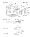
- FIGS. 7A, 7B, 7 C, 7 D and 7 E are diagrams of the subscriber identity card holding mechanism to which a card is loaded;
- FIGS. 8A and 8B are diagrams of a detection switch built in the portable telephone set
- FIG. 9 is an enlarged perspective view showing an operation of drawing the card holder from the portable telephone set
- FIG. 10 is an enlarged perspective view showing an operation of loading the card holder
- FIGS. 11A, 11B and 11 C show another subscriber identity loading mechanism
- FIG. 12 is an enlarged perspective view of a state in which the subscriber identity card loading mechanism is installed in the portable telephone set;
- FIGS. 13A and 13B are diagrams of a card holder
- FIGS. 14A, 14B and 14 C are diagrams of a housing
- FIGS. 15A, 15B and 15 C are diagrams of another detection switch.
- FIGS. 2A and 2B are diagrams of a portable telephone set 30 which can be applied to the GSM according to an embodiment of the present invention. Further, FIG. 3 is an exploded perspective view of the portable telephone set 30 . FIG. 4 is an enlarged perspective view taken along arrow III shown in FIG. 2B.
- the portable telephone set 30 has a front case 32 and a back case 34 between which a printed wiring board unit 36 is interposed.
- the whole case of the portable telephone set 30 includes the cases 32 and 34 .
- the front case 32 is equipped with a key group sheet 31 on which a plurality of keys are arranged.
- the back case 34 is equipped with an antenna 37 .
- the printed wiring board unit 36 is equipped with a liquid crystal unit 35 .
- the front case 32 , the rear case and the printed wiring board unit 36 are longitudinal in directions Y 1 and Y 2 .
- a housing 51 which will be described in detail later, is attached to the printed wiring board unit 36 .
- the portable telephone set 30 has a front surface facing in a direction Z 1 and a back surface facing in a direction Z 2 .
- a plurality of keys 39 are arranged in a front surface 30 a of the portable telephone set 30 so that the keys 39 occupy an area located in a direction Y 2 with respect to the center in the longitudinal direction.
- a display window 40 of the liquid crystal unit 35 and an acoustic output part 41 formed of a speaker are provided in an area located in a direction Y 1 with respect to the keys 39 .
- An acoustic output part 42 formed of a microphone is provided in the area located in the direction Y 2 with respect to the key
- a battery pack mounting portion 45 is provided to the back surface 30 b of the portable telephone set 30 and is located in the area extending in the direction Y 2 from the center in the longitudinal direction. In other words, the battery pack mounting portion 45 is located in the portion corresponding to the arrangement of the keys 39 .
- a battery pack 46 having a length approximately equal to half the length of the portable telephone set 30 is mounted on the battery pack mounting portion 45 .
- the battery pack mounting portion 45 has a recess which causes the back surface 30 b of the portable telephone set 30 with the battery pack 46 mounted to be a flat surface.
- a portion 47 which is adjacent to the battery pack mounting portion 45 in the longitudinal direction and totally occupies the whole located in the direction Y 1 with respect to the battery pack mounting portion 45 , has a projection projecting from a bottom surface 45 a in the direction Z 1 .
- the portion 47 will be referred to as a battery pack mount adjacent portion
- the interface between the battery pack mounting portion 45 and the battery pack adjacent portion 47 is a vertical wall 45 b which stands upright in the direction Z 1 from the bottom surface 45 a .
- a card holder inserting opening 45 - b is formed in a lower end portion of the vertical wall 45 b .
- the lower side of the vertical wall 45 b corresponds to the position in which the card holder insertion opening 45 - b is formed.
- the card holder 52 when the card holder 52 is placed on the bottom surface 45 a of the battery pack mounting portion 45 of the portable telephone set 30 , the card holder 52 faces the card holder insertion opening 45 - b.
- the portable telephone set 30 has a subscriber identity card loading mechanism 50 , which is provided in an inner space 47 a of the battery pack mount adjacent portion 47 .
- the mechanism 50 is built in the portable telephone set 30 without any increase in the thickness thereof because the battery pack mount adjacent portion 47 projects from the bottom surface 45 a of the battery pack mounting portion 45 , and is located in the area which has a larger spatial margin than the other area of the portable telephone set 30 . Further, the size of the card loading mechanism 50 itself is small.
- the thickness of the portable telephone set 30 which is denoted as t 10 , is equal to that obtained when the card loading mechanism 50 is not installed.
- the card loading mechanism 50 includes the housing 51 and the card holder 52 which holds the subscriber identity card 22 and is attached to the housing 51 .
- the card loading mechanism 50 has an upper surface facing in the direction Z 1 , a lower surface in the direction Z 2 , a front surface in the direction Y 2 , and a rear portion in the direction Y 1 .
- the width of the mechanism 50 extends in the directions X 1 and X 2 .
- the subscriber identity card 22 includes a built-in integrated circuit 22 a and six electrodes 22 b provided to the lower surface of the card 22 . Further, the subscriber identity card 22 has a chamfered corder 22 c.
- the card holder 52 is a synthetic resin molded component, and has a flat shape which is long in the directions Y 1 and Y 2 .
- the card holder 52 includes a subscriber identity card accommodating. portion 52 a provided to the lower surface side, a front panel portion 52 b , and a cantilever plate spring 52 c provided to the upper surface side. Further, the card holder 52 has rail portions 52 d and 52 e which are provided to ends thereof located in the directions X 1 and X 2 and extend in the directions Y 1 and Y 2 .
- the subscriber identity card accommodating portion 52 a has a size which corresponds to the subscriber identity card 22 , and a depth “a” corresponding to the thickness t 20 of the card 22 so that the card accommodating portion 52 a has a flat recess shape into which the subscriber identity card can be accommodated.
- the card accommodating portion 52 a includes a slant portion 52 a - 1 , which corresponds to the chamfered corner 22 a .
- Two plate springs 52 a - 2 and 52 a - 3 made of synthetic resin are provided to the end X 2 of the card accommodating portion 52 a so that the free ends thereof face each other and are arranged in a line in the directions Y 1 and Y 2 .
- the plate springs 52 a - 2 and 52 a - 3 can be resiliently bent in the direction X 2 .
- the plate springs 52 a - 2 and 52 a - 3 function as subscriber identity card holding portions having a spring property.
- holes 52 a - 4 and 52 - 5 for pushing out the subscriber identity card are formed in the vicinity of the ends of the bottom of the card accommodating portion 52 a in the direction Y 1 .
- the front panel portion 52 b has a U-shaped cutout portion 52 b - 1 located at the center thereof.
- Protrusions 52 b - 2 and 52 b - 3 which protrude in the direction Z 1 are provided on both sides of the U-shaped cutout portion 52 b - 1 .
- the U-shaped cutout portion 52 b - 1 functions to accommodate a handle portion 52 c - 3 which will be described in detail later.
- the protrusions 52 b - 2 and 52 b - 3 come into contact with a counter U-shaped frame portion 51 a - 4 a which will also be described later.
- the cantilever plate spring 52 c is integrally formed when molding the card holder 52 , and is formed so that a portion of the upper surface of the card holder 52 in the width direction (in the directions X 1 and X 2 ) is cut and raised.
- the plate spring 52 c has a width W 1 that is approximately equal to 1 ⁇ 4 of the width W 2 of the card holder 52 .
- the plate spring 52 c has a root portion 52 c - 1 located in the center of the card holder 52 in the directions Y 1 and Y 2 .
- the root portion 52 c - 1 stands upright by a distance “b” so that the remaining portion of the plate spring 52 c horizontally extends to the front panel portion 52 b in the direction Y 2 .
- the cantilever plate spring 52 c has an engagement craw 52 c - 2 that is located in the center of the upper surface thereof and projects in the direction Z 1 . Further, the cantilever plate spring 52 c has the handle portion 52 c - 3 located at the end thereof.
- the engagement craw 52 c - 2 has a slant surface 52 c - 2 a in the direction Y 1 , and a vertical surface 52 c - 2 b in the direction Y 2 .
- the handle portion 52 c - 3 has a recess portion 52 c - 3 a on the upper surface oriented in the direction Y 1 .
- the recess portion 52 c - 3 a makes it possible for the end of the forefinger of the hand of the operator to be easily engaged with the handle 52 c - 3 . Further, the handle portion 52 c - 3 is located in the U-shaped cutout portion 52 b - 1 of the front panel portion 52 b.
- the housing 51 includes a housing main body 51 a made of synthetic resin, a plurality of terminals 51 b fixed to the housing main body 51 a , and a detection switch 51 c provided to the housing main body 51 a .
- the housing 51 has a size greater than the card holder 52 .
- the housing main body 51 a includes a bottom plate portion 51 a - 1 , sidewall portions 51 a - 2 and 51 a - 3 , and a counter U-shaped frame portion 5 l a - 4 .
- the sidewall portions 51 a - 2 and 52 - 3 which are located on both the sides of the housing main body 51 a in the directions X 1 and X 2 and extend upwards in the direction Z 1 .
- the counter frame portion 51 a - 4 are located on both the sides in the direction Y 2 .
- Guide grooves 51 a - 5 and 51 - 6 are formed in the parts of the sidewall portions 51 a - 2 and 51 a - 3 which face the bottom plate portion 51 a - 1 .
- a guard holder accommodating portion 51 d is formed on the upper surface side of the bottom plate portion 51 a - 1 .
- the guard holder accommodating portion 51 d has a flat space partitioned by the sidewall portions 51 a - 2 and 51 a - 3 .
- the counter U-shaped frame portion 51 a - 4 forms an entrance 51 e to the card holder accommodating portion 51 d .
- Two bosses 51 a - 1 a and 51 a - 1 b for defining the attachment position of the housing 51 are formed on the lower surface of the bottom plate portion 51 a - 1 .
- the counter U-shaped frame portion 51 a - 4 includes a central counter U-shaped frame portion 51 a - 4 a , which is a step portion higher than the frame portion 51 a - 4 .
- the portion 51 a - 4 a is provided to allow the cantilever plate spring 52 c of the card holder 52 to pass therethrough.
- Two upright portions 51 a - 4 b and 51 a - 4 c located on both sides of the frame portion 51 a - 4 a receive the protrusions 52 b - 2 and 52 b - 3 when the card holder 52 is inserted.
- a cut portion 51 a - 4 e having a U shape corresponding to the size of the engagement craw 52 c - 2 is formed in an end of the frame portion 51 a - 4 a extending in the direction Y 1 .
- the frame portion 51 a - 4 d functions as an engagement portion with which the engagement craw 52 c - 2 is engaged.
- the six terminal members 51 b are fixed to the upper surface 51 a - 1 a of the bottom plate portion 51 a - 1 .
- Arc-shaped terminal portions 51 b - 1 are respectively provided on the ends of the six terminal members 51 b so as to correspond to the six electrodes 22 b of the subscriber identity card 22 .
- Terminal portions 51 b - 2 provided on the other ends of the six terminal members 51 b extend outwards from the ends in the directions Y 1 and Y 2 .
- the terminal portions 51 b - 2 have the same height as that of the lower surface 51 a - 1 b of the bottom plate portion 51 a - 1 .
- the detection switch 51 c has a first contact member 51 c - 1 and an L-shaped second contact member 51 c - 2 , and is normally closed.
- the first contact member 51 c - 1 and the second contact member 51 c - 2 are fixed to the lower surface 51 a - 1 b of the bottom plate portion 51 a - 1 .
- the first contact member 51 c - 1 has one end located in the direction Y 1 , which end is fixed, while the other end thereof can flexibly be bent.
- the first contact 51 c - 1 has a convex portion 51 c - 1 a protruding in the direction Z 1 .
- the convex portion 51 c - 1 a slightly protrudes from the upper surface 51 a - 1 a of the bottom plate portion 51 a - 1 via an opening window 51 a - 1 c of the bottom plate portion 51 a - 1 .
- the opening window 51 a - 1 c (the convex portion 51 c -l a ) is disposed in a position in which the opening window 51 a - 1 c is pushed by the subscriber identity card 22 held in the card holder 52 when the card holder 52 is inserted into the housing 51 .
- the printed wiring board unit 36 has a flexible printed circuit board used to attach the housing 51 thereto.
- the flexible printed circuit board 60 extending from the inside of the printed wiring board unit 36 is folded and adheres to the upper surface of the unit 36 .
- a plurality of lands 61 are provided to the flexible printed circuit board 60 so as to have an arrangement which corresponds to the terminal portions 51 b - 2 .
- Holes 62 are formed in the upper surface of the unit 36 and the board 60 so that the positions of the holes 62 correspond to those of the bosses 51 a - 1 a and 51 a - 1 b.
- the housing 51 is positioned so that the bosses 51 a - 1 a and 51 a - 1 b are engaged with the holes 62 .
- the terminal portions 51 b - 2 are soldered to the lands 61 .
- the housing 51 is mounted on the upper surface of the printed wiring board unit 36 so that the entrance 51 e is oriented along the direction Y 2 .
- the housing 51 can completely be accommodated in the battery pack mount adjacent portion 47 , and the entrance 51 e faces a card holder insertion opening 45 b - 1 of the vertical wall 45 b in the state in which the printed wiring board unit 36 is covered by the front case 32 and the back case 34 .
- a finger inserting recess portion 45 b - 2 is formed in the vertical wall 45 b in addition to the card holder insertion opening 45 b - 1 , which opening has a shape corresponding to the front panel portion 52 b of the card holder 52 .
- the finger inserting recess portion 45 b - 2 makes it easy for the forefinger of the operator to engage with the handle portion 52 c - 3 .
- the finger inserting recess portion 45 b - 2 is located just above the card holder insertion opening 45 b - 1 , and is recessed in the direction Y 1 so that the degree of recess is increased in the direction Z 2 .
- the above procedure is comprised of the following first to fifth steps.
- the first step is to detach the battery pack 46 from the portable telephone set 30 .
- the second step is to take out the card holder 52 having no card.
- the third step is to insert the own subscriber identity card 22 into the card holder 52 .
- the fourth step is to load the card holder 52 with the card 22 inserted therein to the housing 51 .
- the fifth step is to attach the battery pack 46 .
- the battery pack 46 is detached from the portable telephone set 30 . Hence, as shown in FIG. 4, the handle portion 52 c - 3 is exposed.
- the card holder 52 is released from the locked state in which it is locked to the housing 51 .
- the forefinger 70 strongly engages with the recess portion 52 c - 3 a of the handle portion 52 c - 3 .
- the craw portion 52 c - 2 passes below the frame portion 51 a - 4 a , so that the card holder 52 is drawn to the outside of the housing 51 .
- the card holder 52 can be drawn by the operation of only the forefinger.
- the subscriber identity card 22 of the operator is inserted in the card holder 52 .
- the card 22 is lightly pushed in the subscriber identity card accommodating portion 52 a in the direction reverse to the direction shown in FIG. 6A so that the card accommodating portion 52 a faces up. hence, the plate springs 52 a - 2 and 52 a - 3 are resiliently bent, so that the card 22 is loaded to the card holder 52 .
- the card holder 52 is detached from the portable telephone set 30 .
- the card 22 can be correctly loaded to the card holder 52 due to the function of the chamfered portion 22 c of the card 22 and the slant portion 52 - 1 of the card accommodating portion 52 a .
- the card 22 is pushed in the single direction by the plate springs 52 a - 2 and 52 a - 3 . Hence, even when the card holder 52 is turned reversely so that the card accommodating portion 52 a faces down, the card 22 does not drop off.
- the card holder 52 is inserted into and loaded to the housing 51 .
- the card holder 52 is placed on the bottom surface 45 a of the battery pack loading portion 45 of the portable telephone set 30 so that the card holder 52 faces the card holder insertion opening 45 b - 1 . Then, the card holder 52 is made to slide in the direction Y 1 so that it passes through the card holder insertion opening 45 b - 1 . Hence, the card holder 52 is inserted into the housing 51 .
- the card holder 52 faces the card holder insertion opening 45 b - 1 .
- This arrangement facilitates the operation of orienting the card holder 52 toward the card holder insertion opening 45 b - 1 , so that the card holder 52 can easily be loaded to the housing 51 .
- the card holder 52 is guided and regulated in the directions X 1 , X 2 , Z 1 and Z 2 so that the rail portions 52 d and 52 e engages with the guide grooves 51 a - 5 and 51 a - 6 of the housing 51 . As shown in FIG. 4, the card holder 52 is inserted until the handle portion 52 c - 3 is engaged with the card holder insertion opening 45 b - 1 .
- the card holder 52 is prevented from moving in the direction Z 1 because the rail portions 52 d and 52 e engage with the guide grooves 51 a - 5 and 51 a - 6 .
- the subscriber identity card 22 is prevented from moving in the direction Z 1 due to the function of the card holder 52 . Hence, the subscriber identity card 22 cannot move in the direction Z 1 .
- the engagement craw 52 c - 2 passes through the central counter U-shaped frame portion 51 a - 4 a , and the cantilever plate spring 52 c is resiliently returned to the original state. Further, the vertical surface 52 c - 2 b of the engagement craw 52 c - 2 engages with the frame portion 51 a - 4 a . Thus, the card holder 52 is locked to the housing 51 and is prevented from being detached therefrom.
- the six electrodes 22 b of the subscriber identity card 22 come into contact with the six arc-shaped terminal portions 51 b - 1 .
- the lower surface 22 e of the subscriber identity card pushes down the convex portion 51 c - 1 a .
- the first contact member 51 c - 1 is detached from the second contact member 51 c - 2 and the detection switch 51 c is opened.
- Information which indicates that the subscriber identity card 22 has been loaded to the card holder 52 is supplied to a given circuit of the portable telephone set 30 .
- the subscriber identity card 22 cannot move in the direction Z 1 .
- the contacts between the electrodes 22 b and the terminal portions 51 b - 1 can be definitely established and the detection switch 51 c can be definitely closed.
- the battery pack 46 is attached to the portable telephone set 30 .
- the portable telephone set 30 is switched to a state in which the owner of the subscriber identity card 22 can be identified. Since the detection switch 51 c is opened, the portable telephone set 30 operates normally.
- the handle portion 52 c - 3 is hidden by the battery pack 46 .
- the subscriber identity card 22 cannot be detached from the portable telephone set 30 in the state in which the battery pack 46 is attached thereto. As a result, there is no possibility that the subscriber identity card 22 happens to be detached from the portable telephone set 30 .
- the detection switch 51 c is closed in the state in which the card holder 52 with no card is loaded to the portable telephone set 30 , which is not thus operated. Hence, it is possible to prevent the occurrence of the wasteful calling procedure which is encountered in the prior art.
- the card holder 52 with the card 22 attached can be detached as described above.
- the-cantilever plate spring 52 c is located, by a relatively large distance “c”, above the upper surface of the subscriber identity card 22 loaded to the card holder 52 .
- the engagement craw 52 c - 2 can be certainly detached from the central counter U-shaped frame portion 51 a - 4 a .
- the subscriber identity card 22 is detached from the card holder 52 , the card 22 is pushed by a tip end of a ballpoint pen or the like, which is inserted in the hole 52 a - 4 and/or 52 a - 5 . Hence, the subscriber identity card 22 can easily be detached.
- FIGS. 11A, 11B, 11 C, 12 , 13 , 14 A, 14 B and 14 C A description will now be given of another subscriber identity card loading mechanism 50 A by referring to FIGS. 11A, 11B, 11 C, 12 , 13 , 14 A, 14 B and 14 C.
- the subscriber card loading mechanism 50 A includes a housing 51 A and a card holder 52 A, which holds the subscriber identity card 22 and is loaded to the housing 51 A.
- the subscriber card loading mechanism 50 A has a structure in which the card holder 52 A has handle portions located on sides X 1 and X 2 .
- the other portions of the card loading mechanism 50 A are the same as corresponding those of the card loading mechanism 50 .
- handle portions 52 A c - 3 A and 52 A c - 3 b are provided on the sides X 1 and X 2 of a front panel portion 52 A b .
- the handle portion 52 A c - 3 a is provided to a spring portion 52 A c , which has an engagement craw 52 A c - 2 located at the tip end of the spring portion 52 A a .
- the spring portion 52 A a is resiliently bent in the width direction of the portable telephone set 30 A.
- the card holder 52 A is inserted so that the rail portions are guided by guide grooves of the housing 51 A.
- the engagement craw 52 A c - 2 engages with a recess portion 51 A b of the housing 51 A.
- a card holder insertion opening 45 A b - 1 is formed in a vertical wall 45 A b of a battery pack mounting portion 45 A of the portable telephone set 30 A. Further, finger insertion recess portions 45 A b - 2 a and 45 A b - 2 b are formed on the sides X 1 and X 2 of the card holder insertion opening 45 A b - 1 .
- a thumb finger 75 is inserted into the recess portion 45 A b - 2 b , and the forefinger 70 is inserted into a finger insertion opening 45 A b - 2 ba .
- the handle portions 52 A c - 3 a and 52 A c - 3 b are slightly gripped, and the spring portion 52 A c is bent so that the engagement craw 52 A c - 2 is drawn from the recess portion 51 A p .
- the card holder 52 A is drawn in the direction Y 2 , and is finally detached from the housing 51 A.
- the card holder 52 A can be drawn to the table while gripping the handle portions 52 A c - 3 a and 52 A c - 3 b without gripping again.
- FIGS. 15A, 15B and 15 C show a variation of the detection switch 51 c .
- a detection switch 51 A c shown in these figures includes a first contact member 101 and a second contact member 102 .
- the detection switch 51 A c is normally maintained in the closed state, and is located at an end of the subscriber identity card loading mechanism 50 in the direction Y 1 .
- the detection switch 51 A c is pushed by the end surface 22 f of the subscriber identity card 22 located in the direction Y 1 and is thus opened when the card holder with the card 22 loaded thereto is loaded to the housing.
- the detection switch 51 A c provided in the end of the mechanism in the direction Y 1 is attractive when the subscriber identity card has a large number of electrodes, for example, eight electrodes, and a large number of terminal members is required to be formed on the bottom of the housing.
- the above-mentioned embodiments of the present invention are directed to the use of the subscriber identity card.
- the present invention is not limited to the subscriber identity card, and includes any card in which information is stored.
Abstract
Description
- 1. Field of the Invention
- The present invention relates to portable telephone sets, and more particularly to a portable telephone set suitable for a global system for mobile communication (GSM).
- Recently, it has been considered in Japan to employ, as a communication system using portable telephone sets, the GSM which has been employed in Europe. The GSM does not require registration of a telephone number for each portable telephone set. Each individual (subscriber) is assigned to a subscriber identity module in which information concerning the subscriber is stored. If the subscriber exchanges the old portable telephone set by a new one, the subscriber identity module is detached from the old telephone set and is then inserted into the new one. If the rent portable telephone set is used, the subscriber inserts the own subscriber identity module into the set. Thus, the new or rent portable telephone set can be used as the subscriber own portable telephone set.
- It has been considered that the subscriber identity module is realized by a compact subscriber identity card in which an integrated circuit including a memory is built. Such a card has a size of, for instance, 25 mm×15 mm.
- The portable telephone set has been required to be thin and have a structure which enables the subscriber identity card to be easily detached therefrom.
- There is another card which can be inserted into the portable telephone set. Such a card stores information important to the subscriber, such as subscriber identity information and accounting information. It is not desired to easily detach, from the portable telephone set, the information cards suitable for the portable telephone set as described above in terms of privacy protection. The portable telephone set is required to satisfy the above.
- In the present specification, the cards to be attached to the portable telephone sets are referred to as portable telephone information cards. The portable telephone information cards include the above subscriber identity card, and another card which stores information other than the subscriber identity information.
- 2. Description of the Related Art FIGS. 1A and 1B are diagrams of a
portable telephone set 10 for the GSM disclosed in Japanese Laid-Open Patent Application No. 8-265404. A battery pack 11 can be attached to the back surface of theportable telephone set 10. Acard loading mechanism 12 is provided in a bottom surface portion of a batterypack mount portion 13 provided to the back surface of theportable telephone set 10, that is, the back surface of the mounted battery pack 11. The batterypack mount portion 14 has abottom plate 14, in which arectangular opening 15 is formed. - The subscriber identity
card loading mechanism 12 is mainly composed of ahousing 20 and aholder 12. Thehousing 20 is fixed to the inside of the portable telephone set 10, and faces theopening 15. Theholder 21 is joined to the housing by a hinge. - A
subscriber identity card 22 can be mounted as follows. Theholder 21 is rotated and set upright. Then, thesubscriber identity card 22 is inserted into theholder 21, which is then depressed and rotated. Thus, thecard 22 passes through the opening 15 and is engaged with thehousing 20. - The
subscriber identity card 22 can be taken out by the reverse operation. It should be noted that thesubscriber identity card 22 which is mounted cannot be taken out unless the battery pack 11 is taken out. - The above
portable telephone set 10 has the following problems. - The battery
pack mount portion 13 located in the back surface of theportable telephone set 10 includes a slight recess. A circuit board, a tenkey and other components are tightly provided in aportion 16 opposite to the batterypack mount portion 13. Thus, no space is available in which a new mechanism is provided. Thecard loading mechanism 12 is provided in theabove portion 16, and thus has an increased thickness t1. Hence, the thickness t3 of theportable telephone set 10 is equal to the sum of the thickness t2 necessary to provide the circuit board, the tenkey and other components and the thickness t1 of thecard loading mechanism 12. The thickness t3 prevents down-sizing of the portable telephone set 10. - The
holder 21 cannot be detached from thehousing 20. Hence, it is necessary to take theportable telephone 10 by hand in order to take out thesubscriber identity card 22 from theholder 21 and insert thesubscriber identity card 22 into theholder 21. The above is troublesome. Further, thecard loading mechanism 12 has a complex structure. - A detection switch detects the
holder 21 even when theholder 21 having no card is mounted. Hence, if the subscriber dials with no card inserted into theholder 21, the portable telephone set 10 starts a corresponding calling procedure although it is not completed. - It is a general object of the present invention to provide a portable telephone set in which the above disadvantages are eliminated.
- A more specific object of the present invention is to provide a compact portable telephone set having a simplified card loading mechanism.
- The above objects of the present invention are achieved by a portable telephone set comprising: a case having first and second sides opposite to each other; a group of keys located on the first side of the case; and a card loading mechanism. The case includes first and second portions located on the second side. The first portion can accommodate a battery pack, and the second portion is next to the first portion and accommodates the card loading mechanism. A card in which information is stored can be loaded to the card loading mechanism. The card loading mechanism and the battery pack can be arranged side by side, so that the thickness of the portable telephone set can be reduced.
- The above portable telephone set may be configured so that: the case has a wall interposed between the first and second portions; and the wall has an opening through which the card can be inserted into the second portion and loaded to the card loading mechanism. Hence, the card cannot be detached unless the battery pack is detached. Thus, it is possible to prevent the card from happening to be detached from the portable telephone set.
- The portable telephone set may be configured so that the second portion includes a protrusion with respect to a bottom portion of the first portion. Such a protrusion means that there is a comparatively large spatial area in the portable telephone set. Hence, the card loading mechanism can be provided in the second portion without a particular difficulty.
- The portable telephone set may be configured so that the card loading mechanism comprises: a housing located in the second portion; and a card holder having a card accommodating portion in which the card can be accommodated, the card holder having a spring portion which portion has a handle portion with which a finger can be engaged, and an engagement craw which can engage with a part of the housing when the card holder is inserted into the housing. A simple structure of the card loading mechanism can be realized.
- The portable telephone set may be configured so that the spring portion is formed of a resin. Thus, the spring portion having a resilient property can be realized with ease.
- The portable telephone set may be configured so that: the spring portion is formed of a resin and can be resiliently bent in a thickness direction of the portable telephone set; and the handle portion is located in a free end of the spring portion. The card holder can easily be drawn by a single-finger operation.
- The portable telephone set may be configured so that: the spring portion is formed of a resin and can be resiliently bent in a thickness direction of the portable telephone set; the handle portion is located in a free end of the spring portion; and the card holder has another handle portion located opposite to the handle portion. The card holder can easily be drawn by using two fingers such as the thumb finger and the forefinger.
- The portable telephone set may be configured so that: the card holder has a card holding portion having a spring property and projecting from a side of the card accommodating portion; and the card holding portion engages with a part of the card so that the card can be restricted in the second portion. The card holding portion of the card holder can certainly hold the card.
- The portable telephone set may be configured so that the card loading mechanism comprises: a housing located in the second portion; a card holder having a card accommodating portion in which the card can be accommodated; and a detection switch which detects a situation in which the card holder with the card loaded thereto is inserted into the housing. Hence, even if the card holder with no card accommodated therein is loaded to the portable telephone set, the portable telephone set can be prevented from performing a meaningless or wasteful operation such as a calling procedure.
- The portable telephone set may be configured so that the detection switch has a terminal having a spring property, the terminal which can be engaged with the card accommodated in the card holder. The same advantages as described above can be obtained.
- The portable telephone set may be configured so that the card holder has a spring portion which portion has a handle portion with which a finger can be engaged, and an engagement craw which can engage with a part of the housing when the card holder is inserted into the housing. The card holding portion of the card holder can certainly hold the card.
- The portable telephone set may be configured so that the card loading mechanism can receive the card in a state in which the battery pack is detached from the first portion. Hence, the card can be prevented from being drawn in the state in which the battery pack is attached to the portable telephone set.
- Other objects, features and advantages of the present invention will become more apparent from the following detailed description when read in conjunction with the accompanying drawings, in which:
- FIGS. 1A and 1B are diagrams of a conventional portable telephone set;
- FIG. 2A is a partially-cutout plan view of a portable telephone set according to an embodiment of the present invention;
- FIG. 2B is a cross-sectional view of the portable telephone set shown in FIG. 2A;
- FIG. 3 is an exploded perspective view of the portable telephone set shown in FIGS. 2A and 2B;
- FIG. 4 is an enlarged perspective view taken along an arrow III shown in FIG. 2B;
- FIG. 5 is a perspective view of a subscriber identity card loading mechanism of the portable telephone set;
- FIG. 6 is a perspective view of a card holder of the portable telephone set;
- FIGS. 7A, 7B, 7C, 7D and 7E are diagrams of the subscriber identity card holding mechanism to which a card is loaded;
- FIGS. 8A and 8B are diagrams of a detection switch built in the portable telephone set;
- FIG. 9 is an enlarged perspective view showing an operation of drawing the card holder from the portable telephone set;
- FIG. 10 is an enlarged perspective view showing an operation of loading the card holder
- FIGS. 11A, 11B and 11C show another subscriber identity loading mechanism;
- FIG. 12 is an enlarged perspective view of a state in which the subscriber identity card loading mechanism is installed in the portable telephone set;
- FIGS. 13A and 13B are diagrams of a card holder;
- FIGS. 14A, 14B and 14C are diagrams of a housing; and
- FIGS. 15A, 15B and 15C are diagrams of another detection switch.
- FIGS. 2A and 2B are diagrams of a portable telephone set 30 which can be applied to the GSM according to an embodiment of the present invention. Further, FIG. 3 is an exploded perspective view of the portable telephone set 30. FIG. 4 is an enlarged perspective view taken along arrow III shown in FIG. 2B.
- The portable telephone set 30 has a
front case 32 and aback case 34 between which a printedwiring board unit 36 is interposed. The whole case of the portable telephone set 30 includes thecases front case 32 is equipped with akey group sheet 31 on which a plurality of keys are arranged. Theback case 34 is equipped with anantenna 37. The printedwiring board unit 36 is equipped with aliquid crystal unit 35. Thefront case 32, the rear case and the printedwiring board unit 36 are longitudinal in directions Y1 and Y2. Ahousing 51, which will be described in detail later, is attached to the printedwiring board unit 36. The portable telephone set 30 has a front surface facing in a direction Z1 and a back surface facing in a direction Z2. - A plurality of
keys 39 are arranged in afront surface 30 a of the portable telephone set 30 so that thekeys 39 occupy an area located in a direction Y2 with respect to the center in the longitudinal direction. Adisplay window 40 of theliquid crystal unit 35 and anacoustic output part 41 formed of a speaker are provided in an area located in a direction Y1 with respect to thekeys 39. Anacoustic output part 42 formed of a microphone is provided in the area located in the direction Y2 with respect to the key - A battery
pack mounting portion 45 is provided to theback surface 30 b of the portable telephone set 30 and is located in the area extending in the direction Y2 from the center in the longitudinal direction. In other words, the batterypack mounting portion 45 is located in the portion corresponding to the arrangement of thekeys 39. Abattery pack 46 having a length approximately equal to half the length of the portable telephone set 30 is mounted on the batterypack mounting portion 45. The batterypack mounting portion 45 has a recess which causes theback surface 30 b of the portable telephone set 30 with thebattery pack 46 mounted to be a flat surface. Aportion 47, which is adjacent to the batterypack mounting portion 45 in the longitudinal direction and totally occupies the whole located in the direction Y1 with respect to the batterypack mounting portion 45, has a projection projecting from abottom surface 45 a in the direction Z1. Hereinafter, theportion 47 will be referred to as a battery pack mount adjacent portion The interface between the batterypack mounting portion 45 and the battery packadjacent portion 47 is avertical wall 45 b which stands upright in the direction Z1 from thebottom surface 45 a. A card holder inserting opening 45-b is formed in a lower end portion of thevertical wall 45 b. The lower side of thevertical wall 45 b corresponds to the position in which the card holder insertion opening 45-b is formed. Hence, as will be described in detail later with reference to FIG. 10, when thecard holder 52 is placed on thebottom surface 45 a of the batterypack mounting portion 45 of the portable telephone set 30, thecard holder 52 faces the card holder insertion opening 45-b. - The portable telephone set 30 has a subscriber identity
card loading mechanism 50, which is provided in an inner space 47 a of the battery pack mountadjacent portion 47. Themechanism 50 is built in the portable telephone set 30 without any increase in the thickness thereof because the battery pack mountadjacent portion 47 projects from thebottom surface 45 a of the batterypack mounting portion 45, and is located in the area which has a larger spatial margin than the other area of the portable telephone set 30. Further, the size of thecard loading mechanism 50 itself is small. The thickness of the portable telephone set 30, which is denoted as t10, is equal to that obtained when thecard loading mechanism 50 is not installed. - A description will be given, with reference to FIGS. 5, 6 and 7A through 7E, of the structure of the subscriber identity
card loading mechanism 50. - The
card loading mechanism 50 includes thehousing 51 and thecard holder 52 which holds thesubscriber identity card 22 and is attached to thehousing 51. Thecard loading mechanism 50 has an upper surface facing in the direction Z1, a lower surface in the direction Z2, a front surface in the direction Y2, and a rear portion in the direction Y1. The width of themechanism 50 extends in the directions X1 and X2. - As shown in FIG. 6, the
subscriber identity card 22 includes a built-inintegrated circuit 22 a and sixelectrodes 22 b provided to the lower surface of thecard 22. Further, thesubscriber identity card 22 has a chamferedcorder 22 c. - The
card holder 52 is a synthetic resin molded component, and has a flat shape which is long in the directions Y1 and Y2. Thecard holder 52 includes a subscriber identity card accommodating.portion 52 a provided to the lower surface side, afront panel portion 52 b, and acantilever plate spring 52 c provided to the upper surface side. Further, thecard holder 52 hasrail portions 52 d and 52 e which are provided to ends thereof located in the directions X1 and X2 and extend in the directions Y1 and Y2. - The subscriber identity
card accommodating portion 52 a has a size which corresponds to thesubscriber identity card 22, and a depth “a” corresponding to the thickness t20 of thecard 22 so that thecard accommodating portion 52 a has a flat recess shape into which the subscriber identity card can be accommodated. Thecard accommodating portion 52 a includes aslant portion 52 a-1, which corresponds to the chamferedcorner 22 a. Two plate springs 52 a-2 and 52 a-3 made of synthetic resin are provided to the end X2 of thecard accommodating portion 52 a so that the free ends thereof face each other and are arranged in a line in the directions Y1 and Y2. The plate springs 52 a-2 and 52 a-3 can be resiliently bent in the direction X2. The plate springs 52 a-2 and 52 a-3 function as subscriber identity card holding portions having a spring property. Further, holes 52 a-4 and 52-5 for pushing out the subscriber identity card are formed in the vicinity of the ends of the bottom of thecard accommodating portion 52 a in the direction Y1. - The
front panel portion 52 b has aU-shaped cutout portion 52 b-1 located at the center thereof.Protrusions 52 b-2 and 52 b-3 which protrude in the direction Z1 are provided on both sides of theU-shaped cutout portion 52 b-1. TheU-shaped cutout portion 52 b-1 functions to accommodate ahandle portion 52 c-3 which will be described in detail later. Theprotrusions 52 b-2 and 52 b-3 come into contact with a counterU-shaped frame portion 51 a-4 a which will also be described later. - The
cantilever plate spring 52 c is integrally formed when molding thecard holder 52, and is formed so that a portion of the upper surface of thecard holder 52 in the width direction (in the directions X1 and X2) is cut and raised. Theplate spring 52 c has a width W1 that is approximately equal to ¼ of the width W2 of thecard holder 52. Theplate spring 52 c has aroot portion 52 c-1 located in the center of thecard holder 52 in the directions Y1 and Y2. Theroot portion 52 c-1 stands upright by a distance “b” so that the remaining portion of theplate spring 52 c horizontally extends to thefront panel portion 52 b in the direction Y2. Thecantilever plate spring 52 c has anengagement craw 52 c-2 that is located in the center of the upper surface thereof and projects in the direction Z1. Further, thecantilever plate spring 52 c has thehandle portion 52 c-3 located at the end thereof. Theengagement craw 52 c-2 has aslant surface 52 c- 2a in the direction Y1, and avertical surface 52 c-2 b in the direction Y2. Thehandle portion 52 c-3 has arecess portion 52 c-3 a on the upper surface oriented in the direction Y1. Therecess portion 52 c-3 a makes it possible for the end of the forefinger of the hand of the operator to be easily engaged with thehandle 52 c-3. Further, thehandle portion 52 c-3 is located in theU-shaped cutout portion 52 b-1 of thefront panel portion 52 b. - When the
handle portion 52 c-3 is pushed in the direction Z2, thecantilever plate spring 52 c is bent and theengagement craw 52 c-2 is thus displaced in the direction Z2. Thecantilever plate spring 52 c is located over the upper surface of thecard holder 52 by the distance “b”. Hence, even if thespring portion 52 c is bent, it is not entered into the subscriber identitycard accommodating portion 52 a. - The
housing 51 includes a housingmain body 51 a made of synthetic resin, a plurality ofterminals 51 b fixed to the housingmain body 51 a, and adetection switch 51 c provided to the housingmain body 51 a. Thehousing 51 has a size greater than thecard holder 52. - The housing
main body 51 a includes abottom plate portion 51 a-1,sidewall portions 51 a-2 and 51 a-3, and a counter U-shaped frame portion 5la-4. Thesidewall portions 51 a-2 and 52-3 which are located on both the sides of the housingmain body 51 a in the directions X1 and X2 and extend upwards in the direction Z1. Thecounter frame portion 51 a-4 are located on both the sides in the direction Y2.Guide grooves 51 a-5 and 51-6 are formed in the parts of thesidewall portions 51 a-2 and 51 a-3 which face thebottom plate portion 51 a-1. A guardholder accommodating portion 51 d is formed on the upper surface side of thebottom plate portion 51 a-1. The guardholder accommodating portion 51 d has a flat space partitioned by thesidewall portions 51 a-2 and 51 a-3. The counterU-shaped frame portion 51 a-4 forms anentrance 51 e to the cardholder accommodating portion 51 d. Twobosses 51 a-1 a and 51 a-1b for defining the attachment position of thehousing 51 are formed on the lower surface of thebottom plate portion 51 a-1. - The counter
U-shaped frame portion 51 a-4 includes a central counterU-shaped frame portion 51 a-4 a, which is a step portion higher than theframe portion 51 a-4. Theportion 51 a-4 a is provided to allow thecantilever plate spring 52 c of thecard holder 52 to pass therethrough. Twoupright portions 51 a-4 b and 51 a-4 c located on both sides of theframe portion 51 a-4 a receive theprotrusions 52 b-2 and 52 b-3 when thecard holder 52 is inserted. Acut portion 51 a-4 e having a U shape corresponding to the size of theengagement craw 52 c-2 is formed in an end of theframe portion 51 a-4 a extending in the direction Y1. Theframe portion 51 a-4 d functions as an engagement portion with which theengagement craw 52 c-2 is engaged. - The six
terminal members 51 b are fixed to theupper surface 51 a-1 a of thebottom plate portion 51 a-1. Arc-shapedterminal portions 51 b-1 are respectively provided on the ends of the sixterminal members 51 b so as to correspond to the sixelectrodes 22 b of thesubscriber identity card 22.Terminal portions 51 b-2 provided on the other ends of the sixterminal members 51 b extend outwards from the ends in the directions Y1 and Y2. Theterminal portions 51 b-2 have the same height as that of thelower surface 51 a-1 b of thebottom plate portion 51 a-1. - Referring to FIG. 8A additionally, the
detection switch 51 c has afirst contact member 51 c-1 and an L-shapedsecond contact member 51 c-2, and is normally closed. Thefirst contact member 51 c-1 and thesecond contact member 51 c-2 are fixed to thelower surface 51 a-1 b of thebottom plate portion 51 a-1. Thefirst contact member 51 c-1 has one end located in the direction Y1, which end is fixed, while the other end thereof can flexibly be bent. Thefirst contact 51 c-1 has aconvex portion 51 c-1 a protruding in the direction Z1. More particularly, theconvex portion 51 c-1 a slightly protrudes from theupper surface 51 a-1 a of thebottom plate portion 51 a-1 via anopening window 51 a-1 c of thebottom plate portion 51 a-1. The openingwindow 51 a-1 c (theconvex portion 51 c-la) is disposed in a position in which theopening window 51 a-1 c is pushed by thesubscriber identity card 22 held in thecard holder 52 when thecard holder 52 is inserted into thehousing 51. - When the
subscriber identity card 22 is not inserted into thecard holder 52, thefirst contact member 51 c-1 is in contact with thesecond contact member 51 c-2, as shown in FIG. 8A. Hence, thedetection switch 51 c is maintained in the closed state. - As shown in FIG. 3, the printed
wiring board unit 36 has a flexible printed circuit board used to attach thehousing 51 thereto. The flexible printedcircuit board 60 extending from the inside of the printedwiring board unit 36 is folded and adheres to the upper surface of theunit 36. A plurality oflands 61 are provided to the flexible printedcircuit board 60 so as to have an arrangement which corresponds to theterminal portions 51 b-2.Holes 62 are formed in the upper surface of theunit 36 and theboard 60 so that the positions of theholes 62 correspond to those of thebosses 51 a-1 a and 51 a-1 b. - The
housing 51 is positioned so that thebosses 51 a-1 a and 51 a-1 b are engaged with theholes 62. Theterminal portions 51 b-2 are soldered to thelands 61. Then, thehousing 51 is mounted on the upper surface of the printedwiring board unit 36 so that theentrance 51 e is oriented along the direction Y2. - The
housing 51 can completely be accommodated in the battery pack mountadjacent portion 47, and theentrance 51 e faces a cardholder insertion opening 45 b-1 of thevertical wall 45 b in the state in which the printedwiring board unit 36 is covered by thefront case 32 and theback case 34. - As shown in FIG. 4, a finger inserting
recess portion 45 b-2 is formed in thevertical wall 45 b in addition to the cardholder insertion opening 45 b-1, which opening has a shape corresponding to thefront panel portion 52 b of thecard holder 52. The finger insertingrecess portion 45 b-2 makes it easy for the forefinger of the operator to engage with thehandle portion 52 c-3. The finger insertingrecess portion 45 b-2 is located just above the cardholder insertion opening 45 b-1, and is recessed in the direction Y1 so that the degree of recess is increased in the direction Z2. - In the state in which the
card holder 52 is accommodated in thehousing 51, as shown in FIG. 4, thefront panel portion 52 b is stayed in the cardholder insertion opening 45 b-1, and thehandle portion 52 c-3 projects from the lower end of the finger insertingrecess portion 45 b-2. - Next, a description will be given of a procedure and operation to be carried out when the operator who rents a portable telephone set inserts his or her own
subscriber identity card 22 therein. - The above procedure is comprised of the following first to fifth steps. The first step is to detach the
battery pack 46 from the portable telephone set 30. The second step is to take out thecard holder 52 having no card. The third step is to insert the ownsubscriber identity card 22 into thecard holder 52. The fourth step is to load thecard holder 52 with thecard 22 inserted therein to thehousing 51. The fifth step is to attach thebattery pack 46. - The above first to fifth steps will be described in more detail below.
- In the first step, the
battery pack 46 is detached from the portable telephone set 30. Hence, as shown in FIG. 4, thehandle portion 52 c-3 is exposed. - In the second step, the
card holder 52 having no card is drawn and taken out. As shown in FIG. 9, aforefinger 70 is inserted into the fingerinsertion recess portion 45 b-2. Then, as indicated by anarrow 71, thehandle portion 52 c-3 is pressed in the direction Z2, and is thereafter drawn in the direction Y2 as indicated as indicated by anarrow 72. In the operation of pressing thehandle portion 52 c-3 in the direction Z2, as shown in FIG. 7D, thecantilever plate spring 52 c is bent in the direction Z2, and theengagement craw 52 c-2 is disengaged from the central counterU-shaped frame portion 51 a-4 a. Hence, thecard holder 52 is released from the locked state in which it is locked to thehousing 51. Theforefinger 70 strongly engages with therecess portion 52 c-3 a of thehandle portion 52 c-3. In the subsequent operation, thecraw portion 52 c-2 passes below theframe portion 51 a-4 a, so that thecard holder 52 is drawn to the outside of thehousing 51. - As described above, the
card holder 52 can be drawn by the operation of only the forefinger. - In the third step, the
subscriber identity card 22 of the operator is inserted in thecard holder 52. Thecard 22 is lightly pushed in the subscriber identitycard accommodating portion 52 a in the direction reverse to the direction shown in FIG. 6A so that thecard accommodating portion 52 a faces up. hence, the plate springs 52 a-2 and 52 a-3 are resiliently bent, so that thecard 22 is loaded to thecard holder 52. In this state, thecard holder 52 is detached from the portable telephone set 30. Hence, it is very easy for the operator to load his or her ownsubscriber identity card 22 to the subscriber identitycard accommodating portion 52 a. - The
card 22 can be correctly loaded to thecard holder 52 due to the function of the chamferedportion 22 c of thecard 22 and the slant portion 52-1 of thecard accommodating portion 52 a. Thecard 22 is pushed in the single direction by the plate springs 52 a-2 and 52 a-3. Hence, even when thecard holder 52 is turned reversely so that thecard accommodating portion 52 a faces down, thecard 22 does not drop off. - In the fourth step, the
card holder 52 is inserted into and loaded to thehousing 51. - As shown in FIG. 10, the
card holder 52 is placed on thebottom surface 45 a of the batterypack loading portion 45 of the portable telephone set 30 so that thecard holder 52 faces the cardholder insertion opening 45 b-1. Then, thecard holder 52 is made to slide in the direction Y1 so that it passes through the cardholder insertion opening 45 b-1. Hence, thecard holder 52 is inserted into thehousing 51. When thecard holder 52 is placed on thebottom surface 45 a of the batterypack mounting portion 45, thecard holder 52 faces the cardholder insertion opening 45 b-1. This arrangement facilitates the operation of orienting thecard holder 52 toward the cardholder insertion opening 45 b-1, so that thecard holder 52 can easily be loaded to thehousing 51. - The
card holder 52 is guided and regulated in the directions X1, X2, Z1 and Z2 so that therail portions 52 d and 52 e engages with theguide grooves 51 a-5 and 51 a-6 of thehousing 51. As shown in FIG. 4, thecard holder 52 is inserted until thehandle portion 52 c-3 is engaged with the cardholder insertion opening 45 b-1. - The
card holder 52 is prevented from moving in the direction Z1 because therail portions 52 d and 52 e engage with theguide grooves 51 a-5 and 51 a-6. Thesubscriber identity card 22 is prevented from moving in the direction Z1 due to the function of thecard holder 52. Hence, thesubscriber identity card 22 cannot move in the direction Z1. - As shown in FIG. 7E, when the
engagement craw 52 c-2 comes into contact with the central counterU-shaped frame portion 51 a-4 a, theslant surface 52 c-2 is guided by theframe portion 51 a-4 a, and thecantilever plate sprint 52 c is resiliently bent in the direction Z2. Hence, theengagement craw 52 c-2 enters below theframe portion 51 a-4 a. In other words, thecard holder 52 can be inserted into thehousing 51 by merely pushing thecard holder 52 in the direction Y2 rather than specially depressing thehandle portion 52 c-3. This also makes it easy to load thecard holder 52 to thehousing 51. - When the
card holder 52 is inserted into the final position of thehousing 51, theengagement craw 52 c-2 passes through the central counterU-shaped frame portion 51 a-4 a, and thecantilever plate spring 52 c is resiliently returned to the original state. Further, thevertical surface 52 c-2b of theengagement craw 52 c-2 engages with theframe portion 51 a-4 a. Thus, thecard holder 52 is locked to thehousing 51 and is prevented from being detached therefrom. - When the
card holder 52 is inserted into the final position of thehousing 51, the sixelectrodes 22 b of thesubscriber identity card 22 come into contact with the six arc-shapedterminal portions 51 b-1. As shown in FIG. 8B, thelower surface 22 e of the subscriber identity card pushes down theconvex portion 51 c-1 a. Hence, thefirst contact member 51 c-1 is detached from thesecond contact member 51 c-2 and thedetection switch 51 c is opened. Information which indicates that thesubscriber identity card 22 has been loaded to thecard holder 52 is supplied to a given circuit of the portable telephone set 30. As has been described previously, thesubscriber identity card 22 cannot move in the direction Z1. Hence, the contacts between theelectrodes 22 b and theterminal portions 51 b-1 can be definitely established and thedetection switch 51 c can be definitely closed. - In the fifth step, the
battery pack 46 is attached to the portable telephone set 30. In this state, the portable telephone set 30 is switched to a state in which the owner of thesubscriber identity card 22 can be identified. Since thedetection switch 51 c is opened, the portable telephone set 30 operates normally. In the state in which thebattery pack 46 is attached to the portable telephone set 30, thehandle portion 52 c-3 is hidden by thebattery pack 46. Hence, thesubscriber identity card 22 cannot be detached from the portable telephone set 30 in the state in which thebattery pack 46 is attached thereto. As a result, there is no possibility that thesubscriber identity card 22 happens to be detached from the portable telephone set 30. - The
detection switch 51 c is closed in the state in which thecard holder 52 with no card is loaded to the portable telephone set 30, which is not thus operated. Hence, it is possible to prevent the occurrence of the wasteful calling procedure which is encountered in the prior art. - The
card holder 52 with thecard 22 attached can be detached as described above. As shown in FIG. 7C, the-cantilever plate spring 52 c is located, by a relatively large distance “c”, above the upper surface of thesubscriber identity card 22 loaded to thecard holder 52. Hence, even if thecantilever plate spring 52 is bent downwards, it cannot come into contact with thesubscriber identity card 22, and hence theengagement craw 52 c-2 can be certainly detached from the central counterU-shaped frame portion 51 a-4 a. Hence, thesubscriber identity card 22 is detached from thecard holder 52, thecard 22 is pushed by a tip end of a ballpoint pen or the like, which is inserted in thehole 52 a-4 and/or 52 a-5. Hence, thesubscriber identity card 22 can easily be detached. - A description will now be given of another subscriber identity
card loading mechanism 50A by referring to FIGS. 11A, 11B, 11C, 12, 13, 14A, 14B and 14C. - The subscriber
card loading mechanism 50A includes ahousing 51A and acard holder 52A, which holds thesubscriber identity card 22 and is loaded to thehousing 51A. The subscribercard loading mechanism 50A has a structure in which thecard holder 52A has handle portions located on sides X1 and X2. The other portions of thecard loading mechanism 50A are the same as corresponding those of thecard loading mechanism 50. - As shown in FIG. 13A, handle portions 52Ac-3A and 52Ac-3 b are provided on the sides X1 and X2 of a front panel portion 52Ab. The handle portion 52Ac-3 a is provided to a spring portion 52Ac, which has an engagement craw 52Ac-2 located at the tip end of the spring portion 52Aa. Further, the spring portion 52Aa is resiliently bent in the width direction of the portable telephone set 30A. The
card holder 52A is inserted so that the rail portions are guided by guide grooves of thehousing 51A. The engagement craw 52Ac-2 engages with a recess portion 51Ab of thehousing 51A. - As shown in FIG. 12, a card holder insertion opening 45Ab-1 is formed in a vertical wall 45Ab of a battery pack mounting portion 45A of the portable telephone set 30A. Further, finger insertion recess portions 45Ab-2 a and 45Ab-2 b are formed on the sides X1 and X2 of the card holder insertion opening 45Ab-1.
- A
thumb finger 75 is inserted into the recess portion 45Ab-2 b, and theforefinger 70 is inserted into a finger insertion opening 45Ab-2 ba. Then, the handle portions 52Ac-3 a and 52Ac-3 b are slightly gripped, and the spring portion 52Ac is bent so that the engagement craw 52Ac-2 is drawn from the recess portion 51Ap. In this state, thecard holder 52A is drawn in the direction Y2, and is finally detached from thehousing 51A. In the above manner, thecard holder 52A can be drawn to the table while gripping the handle portions 52Ac-3 a and 52Ac-3 b without gripping again. - The operation steps of the subscriber identity
card loading mechanism 50A are the same as those of themechanism 50, and a description thereof will be omitted. - FIGS. 15A, 15B and 15C show a variation of the
detection switch 51 c. A detection switch 51Ac shown in these figures includes afirst contact member 101 and asecond contact member 102. As shown in FIGS. 15A and 15B, the detection switch 51Ac is normally maintained in the closed state, and is located at an end of the subscriber identitycard loading mechanism 50 in the direction Y1. As shown in FIG. 15C, the detection switch 51Ac is pushed by theend surface 22 f of thesubscriber identity card 22 located in the direction Y1 and is thus opened when the card holder with thecard 22 loaded thereto is loaded to the housing. - The detection switch 51Ac provided in the end of the mechanism in the direction Y1 is attractive when the subscriber identity card has a large number of electrodes, for example, eight electrodes, and a large number of terminal members is required to be formed on the bottom of the housing.
- The above-mentioned embodiments of the present invention are directed to the use of the subscriber identity card. However, the present invention is not limited to the subscriber identity card, and includes any card in which information is stored.
- The present invention is not limited to the specifically disclosed embodiments, and variations and modifications may be made without departing from the scope of the present invention.
Claims (12)
Priority Applications (2)
| Application Number | Priority Date | Filing Date | Title |
|---|---|---|---|
| US10/414,449 US7925301B2 (en) | 1997-06-03 | 2003-04-15 | Portable telephone set with a card inserted through a battery holding space |
| US13/037,540 US8666449B2 (en) | 1997-06-03 | 2011-03-01 | Portable telephone set |
Applications Claiming Priority (5)
| Application Number | Priority Date | Filing Date | Title |
|---|---|---|---|
| JP14540797A JP4237834B2 (en) | 1997-06-03 | 1997-06-03 | Mobile phone |
| JP9-145407 | 1997-06-03 | ||
| US09/017,395 US6101372A (en) | 1997-06-03 | 1998-02-02 | Portable telephone set |
| US09/518,827 US6580923B1 (en) | 1997-06-03 | 2000-03-06 | Portable telephone set |
| US10/414,449 US7925301B2 (en) | 1997-06-03 | 2003-04-15 | Portable telephone set with a card inserted through a battery holding space |
Related Parent Applications (1)
| Application Number | Title | Priority Date | Filing Date |
|---|---|---|---|
| US09/518,827 Division US6580923B1 (en) | 1997-06-03 | 2000-03-06 | Portable telephone set |
Related Child Applications (1)
| Application Number | Title | Priority Date | Filing Date |
|---|---|---|---|
| US13/037,540 Continuation US8666449B2 (en) | 1997-06-03 | 2011-03-01 | Portable telephone set |
Publications (2)
| Publication Number | Publication Date |
|---|---|
| US20030195020A1 true US20030195020A1 (en) | 2003-10-16 |
| US7925301B2 US7925301B2 (en) | 2011-04-12 |
Family
ID=26476535
Family Applications (2)
| Application Number | Title | Priority Date | Filing Date |
|---|---|---|---|
| US10/414,449 Expired - Fee Related US7925301B2 (en) | 1997-06-03 | 2003-04-15 | Portable telephone set with a card inserted through a battery holding space |
| US13/037,540 Expired - Fee Related US8666449B2 (en) | 1997-06-03 | 2011-03-01 | Portable telephone set |
Family Applications After (1)
| Application Number | Title | Priority Date | Filing Date |
|---|---|---|---|
| US13/037,540 Expired - Fee Related US8666449B2 (en) | 1997-06-03 | 2011-03-01 | Portable telephone set |
Country Status (1)
| Country | Link |
|---|---|
| US (2) | US7925301B2 (en) |
Cited By (30)
| Publication number | Priority date | Publication date | Assignee | Title |
|---|---|---|---|---|
| US20030134602A1 (en) * | 2000-02-25 | 2003-07-17 | Hideo Haga | Card holding structure and portable terminal apparatus having the same |
| US20060097376A1 (en) * | 2002-08-05 | 2006-05-11 | Leurs Philip R | Electronic product, a body and a method of manufacturing |
| US7137552B1 (en) * | 2003-12-10 | 2006-11-21 | American Express Travel Related Services Company, Inc. | Portable electronic devices interconnected with convenient or foldable transaction cards |
| US20070037431A1 (en) * | 2005-08-12 | 2007-02-15 | Fih Co. Ltd. | Surface contact card holder |
| US20070267494A1 (en) * | 2006-05-18 | 2007-11-22 | Lg Electronics Inc. | Mobile terminal incorporating card removal mechanism |
| US20080084355A1 (en) * | 2004-07-06 | 2008-04-10 | Matsushita Electric Industrial Co., Ltd. | Electronic Device with Built-in Antenna |
| US20080096606A1 (en) * | 2006-10-23 | 2008-04-24 | Samsung Electronics Co. Ltd. | Apparatus for detachably installing a smart card in a portable terminal |
| US7721956B2 (en) | 2003-12-10 | 2010-05-25 | American Express Travel Related Services Company, Inc. | Foldable transaction card systems |
| US7892371B2 (en) | 2002-11-07 | 2011-02-22 | American Express Travel Related Services Company, Inc. | Foldable transaction cards and methods of making the same |
| US20110120901A1 (en) * | 2009-11-20 | 2011-05-26 | Shenzhen Futaihong Precision Industry Co., Ltd. | Device housing and method for making the same |
| EP2348643A1 (en) * | 2010-01-22 | 2011-07-27 | Research In Motion Limited | Release mechanism for a smart card |
| US20110183716A1 (en) * | 2010-01-22 | 2011-07-28 | Ramon Lamers | Release mechanism for a smart card |
| US20110267787A1 (en) * | 2010-04-28 | 2011-11-03 | Fih (Hong Kong) Limited | Chip card holder for portable electronic device |
| US20130072258A1 (en) * | 2010-05-27 | 2013-03-21 | France Telecom | Shell for mobile telephone with nfc functionality |
| CN103457100A (en) * | 2012-06-01 | 2013-12-18 | Smk株式会社 | Disc type pulling part structure of electronic device |
| CN103515784A (en) * | 2012-06-26 | 2014-01-15 | Smk株式会社 | Disc type pull-out part structure of electronic equipment |
| US20140038445A1 (en) * | 2012-08-06 | 2014-02-06 | Fih (Hong Kong) Limited | Chip card holder for electronic device |
| US20140049920A1 (en) * | 2010-04-19 | 2014-02-20 | Apple Inc. | Compact ejectable component assemblies in electronic devices |
| CN103682811A (en) * | 2012-09-14 | 2014-03-26 | Smk株式会社 | Tray for card storage, card storage structure, and electronic equipment using card storage structure |
| CN103682812A (en) * | 2012-09-11 | 2014-03-26 | Smk株式会社 | Tray for card storage, card storage structure, and electronic equipment using card storage structure |
| CN104167639A (en) * | 2013-05-15 | 2014-11-26 | 日本航空电子工业株式会社 | Holder and connector device |
| US20150011129A1 (en) * | 2012-04-20 | 2015-01-08 | Huawei Device Co., Ltd. | Foolproof Structure for Sharing Card Slot Space |
| US20150011118A1 (en) * | 2013-07-02 | 2015-01-08 | Japan Aviation Electronics Industry, Limited | Connector |
| US20150022981A1 (en) * | 2013-07-18 | 2015-01-22 | Molex Incorporated | Electronic card connection device and electronic device |
| US20150230359A1 (en) * | 2014-02-08 | 2015-08-13 | Chiun Mai Communication Systems, Inc. | Chip card holder and portable electronic device with same |
| US20150245507A1 (en) * | 2014-02-27 | 2015-08-27 | Wago Verwaltungsgesellschaft Mbh | Electrical device |
| US20160113142A1 (en) * | 2014-10-17 | 2016-04-21 | Samsung Electronics Co., Ltd. | System for installing removable external component in electronic devices |
| CN105870677A (en) * | 2015-01-23 | 2016-08-17 | 泰科电子日本合同会社 | Card connector and electronic device |
| US20170250480A1 (en) * | 2015-11-30 | 2017-08-31 | Molex, Llc | Card socket for electronic device |
| US10230828B2 (en) * | 2017-05-29 | 2019-03-12 | Kyocera Corporation | Communication device |
Families Citing this family (5)
| Publication number | Priority date | Publication date | Assignee | Title |
|---|---|---|---|---|
| TW200924494A (en) * | 2007-11-30 | 2009-06-01 | Compal Communications Inc | Battery and mobile communication apparatus including the same |
| CN101685932B (en) * | 2008-09-26 | 2012-07-25 | 深圳富泰宏精密工业有限公司 | Chip card fixedly holding structure |
| US20120106103A1 (en) * | 2010-06-23 | 2012-05-03 | Tanios Nohra | Radio frequency energy harvesting enclosure for radio frequency connected devices |
| FR2965438B1 (en) * | 2010-09-23 | 2013-07-05 | Sagem Wireless | MOBILE TERMINAL COMPRISING A HOUSING COMPRISING TWO MOVABLE PARTS ONE TO THE OTHER |
| US8915746B2 (en) | 2013-03-14 | 2014-12-23 | Sierra Wireless | Reverse through-board low profile module connector |
Citations (6)
| Publication number | Priority date | Publication date | Assignee | Title |
|---|---|---|---|---|
| US5257414A (en) * | 1990-11-26 | 1993-10-26 | Motorola, Inc. | Apparatus for accepting and retaining a memory card |
| US5331123A (en) * | 1992-06-01 | 1994-07-19 | Motorola Inc. | Switch operative responsive to positioning of a card member |
| US5465401A (en) * | 1992-12-15 | 1995-11-07 | Texas Instruments Incorporated | Communication system and methods for enhanced information transfer |
| US5625534A (en) * | 1995-05-12 | 1997-04-29 | Dell Computer Corporation | Portable computer having a data card reader apparatus associated therewith |
| US5699406A (en) * | 1994-09-07 | 1997-12-16 | Nokia Mobile Phones Ltd. | Arrangement for securing the SIM card in a mobile telephone |
| US5790659A (en) * | 1996-08-30 | 1998-08-04 | Telefonaktiebolaget Lm Ericsson | Subscriber identity module (SIM) card holder |
Family Cites Families (14)
| Publication number | Priority date | Publication date | Assignee | Title |
|---|---|---|---|---|
| WO1990013952A1 (en) | 1989-05-01 | 1990-11-15 | Motorola, Inc. | Radio and electronic card assembly |
| DE4110768C1 (en) | 1991-03-28 | 1992-11-12 | Hagenuk Gmbh, 2300 Kiel, De | |
| FI913321A0 (en) | 1991-07-09 | 1991-07-09 | Nokia Mobile Phones Ltd | Mobiltelefon. |
| JPH07123262B2 (en) | 1993-03-19 | 1995-12-25 | 日本電気株式会社 | Mobile phone |
| DE4344249A1 (en) | 1993-12-23 | 1995-06-29 | Siemens Ag | Battery-powered transceiver with replaceable radio equipment unit |
| WO1995027923A1 (en) | 1994-04-09 | 1995-10-19 | Lucien Frisch | Color separation process |
| EP0684723A3 (en) | 1994-05-27 | 1998-04-22 | Siemens Aktiengesellschaft | Handheld transceiver |
| IT1266887B1 (en) | 1994-07-22 | 1997-01-21 | Sixtel Spa | DATA TRANSMISSION EQUIPMENT FOR A WIRELESS COMMUNICATION NETWORK. |
| JP3068754B2 (en) | 1994-09-16 | 2000-07-24 | 松下電器産業株式会社 | Plug-in SIM connection device |
| DE19508363C1 (en) | 1995-03-10 | 1996-07-25 | Amphenol Tuchel Elect | Housing for a chip card |
| JP3439868B2 (en) | 1995-03-20 | 2003-08-25 | 富士通株式会社 | Mobile phone |
| JPH08293350A (en) | 1995-04-20 | 1996-11-05 | Casio Comput Co Ltd | Lock mechanism of information recording medium |
| JP3020020B2 (en) | 1995-05-18 | 2000-03-15 | モレックス インコーポレーテッド | Card connector |
| US5815570A (en) | 1995-09-29 | 1998-09-29 | Motorola, Inc. | Communication device with card ejection mechanism |
-
2003
- 2003-04-15 US US10/414,449 patent/US7925301B2/en not_active Expired - Fee Related
-
2011
- 2011-03-01 US US13/037,540 patent/US8666449B2/en not_active Expired - Fee Related
Patent Citations (6)
| Publication number | Priority date | Publication date | Assignee | Title |
|---|---|---|---|---|
| US5257414A (en) * | 1990-11-26 | 1993-10-26 | Motorola, Inc. | Apparatus for accepting and retaining a memory card |
| US5331123A (en) * | 1992-06-01 | 1994-07-19 | Motorola Inc. | Switch operative responsive to positioning of a card member |
| US5465401A (en) * | 1992-12-15 | 1995-11-07 | Texas Instruments Incorporated | Communication system and methods for enhanced information transfer |
| US5699406A (en) * | 1994-09-07 | 1997-12-16 | Nokia Mobile Phones Ltd. | Arrangement for securing the SIM card in a mobile telephone |
| US5625534A (en) * | 1995-05-12 | 1997-04-29 | Dell Computer Corporation | Portable computer having a data card reader apparatus associated therewith |
| US5790659A (en) * | 1996-08-30 | 1998-08-04 | Telefonaktiebolaget Lm Ericsson | Subscriber identity module (SIM) card holder |
Cited By (53)
| Publication number | Priority date | Publication date | Assignee | Title |
|---|---|---|---|---|
| US6947767B2 (en) * | 2000-02-25 | 2005-09-20 | Matsushita Electric Industrial Co., Ltd. | Card holding structure and portable terminal apparatus having the same |
| US20030134602A1 (en) * | 2000-02-25 | 2003-07-17 | Hideo Haga | Card holding structure and portable terminal apparatus having the same |
| US20060097376A1 (en) * | 2002-08-05 | 2006-05-11 | Leurs Philip R | Electronic product, a body and a method of manufacturing |
| US7563990B2 (en) * | 2002-08-05 | 2009-07-21 | Koninklijke Philips Electronics N.V. | Electronic product, a body and a method of manufacturing |
| US7892371B2 (en) | 2002-11-07 | 2011-02-22 | American Express Travel Related Services Company, Inc. | Foldable transaction cards and methods of making the same |
| US7137552B1 (en) * | 2003-12-10 | 2006-11-21 | American Express Travel Related Services Company, Inc. | Portable electronic devices interconnected with convenient or foldable transaction cards |
| US7721956B2 (en) | 2003-12-10 | 2010-05-25 | American Express Travel Related Services Company, Inc. | Foldable transaction card systems |
| US7583227B2 (en) * | 2004-07-06 | 2009-09-01 | Panasonic Corporation | Electronic device with built-in antenna |
| US20080084355A1 (en) * | 2004-07-06 | 2008-04-10 | Matsushita Electric Industrial Co., Ltd. | Electronic Device with Built-in Antenna |
| US20070037431A1 (en) * | 2005-08-12 | 2007-02-15 | Fih Co. Ltd. | Surface contact card holder |
| US7445510B2 (en) * | 2005-08-12 | 2008-11-04 | Shenzhen Futaihong Precision Industry Co., Ltd. | Surface contact card holder |
| US20070267494A1 (en) * | 2006-05-18 | 2007-11-22 | Lg Electronics Inc. | Mobile terminal incorporating card removal mechanism |
| EP1916776A2 (en) | 2006-10-23 | 2008-04-30 | Samsung Electronics Co., Ltd. | Apparatus for detachably installing a smart card in a portable terminal |
| US20080096606A1 (en) * | 2006-10-23 | 2008-04-24 | Samsung Electronics Co. Ltd. | Apparatus for detachably installing a smart card in a portable terminal |
| EP1916776A3 (en) * | 2006-10-23 | 2011-12-14 | Samsung Electronics Co., Ltd. | Apparatus for detachably installing a smart card in a portable terminal |
| US8150466B2 (en) | 2006-10-23 | 2012-04-03 | Samsung Electronics Co., Ltd. | Apparatus for detachably installing a smart card in a portable terminal |
| US20110120901A1 (en) * | 2009-11-20 | 2011-05-26 | Shenzhen Futaihong Precision Industry Co., Ltd. | Device housing and method for making the same |
| US8273986B2 (en) * | 2009-11-20 | 2012-09-25 | Shenzhen Futaihong Precision Industry Co., Ltd. | Device housing and method for making the same |
| EP2348643A1 (en) * | 2010-01-22 | 2011-07-27 | Research In Motion Limited | Release mechanism for a smart card |
| US20110183716A1 (en) * | 2010-01-22 | 2011-07-28 | Ramon Lamers | Release mechanism for a smart card |
| US9385771B2 (en) * | 2010-01-22 | 2016-07-05 | Blackberry Limited | Release mechanism for a smart card |
| US20160100496A1 (en) * | 2010-04-19 | 2016-04-07 | Apple Inc. | Compact ejectable component assemblies in electronic devices |
| US20140049920A1 (en) * | 2010-04-19 | 2014-02-20 | Apple Inc. | Compact ejectable component assemblies in electronic devices |
| US9232668B2 (en) * | 2010-04-19 | 2016-01-05 | Apple Inc. | Compact ejectable component assemblies in electronic devices |
| US10262245B2 (en) * | 2010-04-19 | 2019-04-16 | Apple Inc. | Compact ejectable component assemblies in electronic devices |
| US20110267787A1 (en) * | 2010-04-28 | 2011-11-03 | Fih (Hong Kong) Limited | Chip card holder for portable electronic device |
| US8270175B2 (en) * | 2010-04-28 | 2012-09-18 | Shenzhen Futaihong Precision Industry Co., Ltd. | Chip card holder for portable electronic device |
| CN102238246A (en) * | 2010-04-28 | 2011-11-09 | 深圳富泰宏精密工业有限公司 | Portable electronic device and chip card fixing structure thereof |
| US20130072258A1 (en) * | 2010-05-27 | 2013-03-21 | France Telecom | Shell for mobile telephone with nfc functionality |
| US9491273B2 (en) * | 2010-05-27 | 2016-11-08 | Orange | Shell for mobile telephone with NFC functionality |
| US9219320B2 (en) * | 2012-04-20 | 2015-12-22 | Huawei Device Co., Ltd. | Foolproof structure for sharing card slot space |
| US20150011129A1 (en) * | 2012-04-20 | 2015-01-08 | Huawei Device Co., Ltd. | Foolproof Structure for Sharing Card Slot Space |
| CN103457100A (en) * | 2012-06-01 | 2013-12-18 | Smk株式会社 | Disc type pulling part structure of electronic device |
| CN103515784A (en) * | 2012-06-26 | 2014-01-15 | Smk株式会社 | Disc type pull-out part structure of electronic equipment |
| US8968030B2 (en) * | 2012-08-06 | 2015-03-03 | Zhongshan Innocloud Intellectual Property Services Co., Ltd. | Chip card holder for electronic device |
| US20140038445A1 (en) * | 2012-08-06 | 2014-02-06 | Fih (Hong Kong) Limited | Chip card holder for electronic device |
| CN103682812A (en) * | 2012-09-11 | 2014-03-26 | Smk株式会社 | Tray for card storage, card storage structure, and electronic equipment using card storage structure |
| CN103682811A (en) * | 2012-09-14 | 2014-03-26 | Smk株式会社 | Tray for card storage, card storage structure, and electronic equipment using card storage structure |
| CN104167639A (en) * | 2013-05-15 | 2014-11-26 | 日本航空电子工业株式会社 | Holder and connector device |
| US20150011118A1 (en) * | 2013-07-02 | 2015-01-08 | Japan Aviation Electronics Industry, Limited | Connector |
| US9484655B2 (en) * | 2013-07-02 | 2016-11-01 | Japan Aviation Electronics Industry, Limited | Connector |
| US9445521B2 (en) * | 2013-07-18 | 2016-09-13 | Molex, Llc | Electronic card connection device and electronic device |
| US9907197B2 (en) | 2013-07-18 | 2018-02-27 | Molex, Llc | Electronic card connection device and electronic device |
| US20150022981A1 (en) * | 2013-07-18 | 2015-01-22 | Molex Incorporated | Electronic card connection device and electronic device |
| US20150230359A1 (en) * | 2014-02-08 | 2015-08-13 | Chiun Mai Communication Systems, Inc. | Chip card holder and portable electronic device with same |
| US20150245507A1 (en) * | 2014-02-27 | 2015-08-27 | Wago Verwaltungsgesellschaft Mbh | Electrical device |
| US10070545B2 (en) * | 2014-02-27 | 2018-09-04 | Wago Verwaltungsgesellschaft Mbh | Electrical device |
| US20160113142A1 (en) * | 2014-10-17 | 2016-04-21 | Samsung Electronics Co., Ltd. | System for installing removable external component in electronic devices |
| US9706676B2 (en) * | 2014-10-17 | 2017-07-11 | Samsung Electronics Co., Ltd. | System for installing removable external component in electronic devices |
| CN105870677A (en) * | 2015-01-23 | 2016-08-17 | 泰科电子日本合同会社 | Card connector and electronic device |
| US20170250480A1 (en) * | 2015-11-30 | 2017-08-31 | Molex, Llc | Card socket for electronic device |
| US10381759B2 (en) * | 2015-11-30 | 2019-08-13 | Molex, Llc | Card socket for electronic device |
| US10230828B2 (en) * | 2017-05-29 | 2019-03-12 | Kyocera Corporation | Communication device |
Also Published As
| Publication number | Publication date |
|---|---|
| US8666449B2 (en) | 2014-03-04 |
| US20110151946A1 (en) | 2011-06-23 |
| US7925301B2 (en) | 2011-04-12 |
Similar Documents
| Publication | Publication Date | Title |
|---|---|---|
| US6580923B1 (en) | Portable telephone set | |
| US8666449B2 (en) | Portable telephone set | |
| US6495784B2 (en) | Step keys, step key assembly, and terminal having the step key assembly | |
| US6171138B1 (en) | Electrical connector for removable components | |
| US6766952B2 (en) | SIM card carrier | |
| US6035216A (en) | Device for receiving a SIM card for portable telephone set | |
| US6954653B2 (en) | Cellular phone simultaneously mounting two IC cards and including a lock button for selectively releasing the two IC cards | |
| EP0616458B1 (en) | Portable telephone set combined with a card | |
| US7160131B1 (en) | SIM card holder | |
| US8602299B2 (en) | Mobile terminal device | |
| US7744000B2 (en) | Chip card retaining mechanism | |
| US7445510B2 (en) | Surface contact card holder | |
| US6175505B1 (en) | Device for receiving and connecting a memory card | |
| JP4306143B2 (en) | Mobile phone | |
| GB2328772A (en) | SIM card locking in a portable telephone | |
| JP2002176479A (en) | Smart card reader module | |
| US5883786A (en) | SIM card containment assembly for an electronic apparatus | |
| US20040127101A1 (en) | Sim card receiving mechanism | |
| JP2002032715A (en) | Memory card loading device, electronic equipment equipped with memory card loading device, and memory card adapter device | |
| US7252529B2 (en) | Chip card retaining mechanism | |
| JP2004222170A (en) | Folding portable electronic equipment | |
| JPH01190058A (en) | Tranceiver | |
| US20050075138A1 (en) | Low profile electronic card holder and device using same | |
| JP4751698B2 (en) | Mobile phone | |
| JP2002057767A (en) | Telephone set |
Legal Events
| Date | Code | Title | Description |
|---|---|---|---|
| STCF | Information on status: patent grant |
Free format text: PATENTED CASE |
|
| CC | Certificate of correction | ||
| FEPP | Fee payment procedure |
Free format text: PAYOR NUMBER ASSIGNED (ORIGINAL EVENT CODE: ASPN); ENTITY STATUS OF PATENT OWNER: LARGE ENTITY |
|
| FPAY | Fee payment |
Year of fee payment: 4 |
|
| FEPP | Fee payment procedure |
Free format text: MAINTENANCE FEE REMINDER MAILED (ORIGINAL EVENT CODE: REM.); ENTITY STATUS OF PATENT OWNER: LARGE ENTITY |
|
| LAPS | Lapse for failure to pay maintenance fees |
Free format text: PATENT EXPIRED FOR FAILURE TO PAY MAINTENANCE FEES (ORIGINAL EVENT CODE: EXP.); ENTITY STATUS OF PATENT OWNER: LARGE ENTITY |
|
| STCH | Information on status: patent discontinuation |
Free format text: PATENT EXPIRED DUE TO NONPAYMENT OF MAINTENANCE FEES UNDER 37 CFR 1.362 |
|
| FP | Lapsed due to failure to pay maintenance fee |
Effective date: 20190412 |