US20030195983A1 - Network congestion management using aggressive timers - Google Patents
Network congestion management using aggressive timers Download PDFInfo
- Publication number
- US20030195983A1 US20030195983A1 US10/442,401 US44240103A US2003195983A1 US 20030195983 A1 US20030195983 A1 US 20030195983A1 US 44240103 A US44240103 A US 44240103A US 2003195983 A1 US2003195983 A1 US 2003195983A1
- Authority
- US
- United States
- Prior art keywords
- network system
- frame
- attribute
- end station
- network
- Prior art date
- Legal status (The legal status is an assumption and is not a legal conclusion. Google has not performed a legal analysis and makes no representation as to the accuracy of the status listed.)
- Abandoned
Links
Images


Classifications
-
- H—ELECTRICITY
- H04—ELECTRIC COMMUNICATION TECHNIQUE
- H04L—TRANSMISSION OF DIGITAL INFORMATION, e.g. TELEGRAPHIC COMMUNICATION
- H04L47/00—Traffic control in data switching networks
- H04L47/10—Flow control; Congestion control
- H04L47/12—Avoiding congestion; Recovering from congestion
-
- H—ELECTRICITY
- H04—ELECTRIC COMMUNICATION TECHNIQUE
- H04L—TRANSMISSION OF DIGITAL INFORMATION, e.g. TELEGRAPHIC COMMUNICATION
- H04L47/00—Traffic control in data switching networks
- H04L47/10—Flow control; Congestion control
- H04L47/26—Flow control; Congestion control using explicit feedback to the source, e.g. choke packets
-
- H—ELECTRICITY
- H04—ELECTRIC COMMUNICATION TECHNIQUE
- H04L—TRANSMISSION OF DIGITAL INFORMATION, e.g. TELEGRAPHIC COMMUNICATION
- H04L47/00—Traffic control in data switching networks
- H04L47/10—Flow control; Congestion control
- H04L47/28—Flow control; Congestion control in relation to timing considerations
-
- H—ELECTRICITY
- H04—ELECTRIC COMMUNICATION TECHNIQUE
- H04L—TRANSMISSION OF DIGITAL INFORMATION, e.g. TELEGRAPHIC COMMUNICATION
- H04L49/00—Packet switching elements
- H04L49/35—Switches specially adapted for specific applications
- H04L49/356—Switches specially adapted for specific applications for storage area networks
-
- H—ELECTRICITY
- H04—ELECTRIC COMMUNICATION TECHNIQUE
- H04L—TRANSMISSION OF DIGITAL INFORMATION, e.g. TELEGRAPHIC COMMUNICATION
- H04L49/00—Packet switching elements
- H04L49/50—Overload detection or protection within a single switching element
- H04L49/505—Corrective measures
Definitions
- the present invention generally relates to communication in network systems and more particularly to network system congestion management.
- a traditional network system such as a computer system, has an implicit ability to communicate between its own local processors and from the local processors to its own I/O adapters and the devices attached to its I/O adapters.
- processors communicate with other processors, memory, and other devices via processor-memory buses.
- I/O adapters communicate via buses attached to processor-memory buses.
- the processors and I/O adapters on a first computer system are typically not directly accessible to other processors and I/O adapters located on a second computer system.
- a source process on a first node communicates messages to a destination process on a second node via a transport service.
- a message is herein defined to be an application-defined unit of data exchange, which is a primitive unit of communication between cooperating sequential processes. Messages are typically packetized into frames for communication on an underlying communication services/fabrics.
- a frame is herein defined to be one unit of data encapsulated by a physical network protocol header and/or trailer.
- Congestion control mechanisms typically fall into three categories which include congestion detection mechanisms; congestion reporting mechanisms; and congestion response mechanisms.
- Congestion reporting mechanisms report the occurrence of congestion provided from congestion detection mechanisms possibly for short term use in alleviating congestion and possibly for long term network management.
- the congestion response mechanisms attempt to alleviate or remove congestion.
- Congestion in large distributed computer systems is a significant problem today, especially in infrastructures of remote computer systems having congestion resulting from message traffic over an internet or intranet coupling the remote computer systems.
- Certain conventional distributed computer systems employ various means for addressing network traffic congestion.
- One known method is to drop frames that fail to make forward progress over a defined period of time.
- One realization of the method involves the use of forward progress timers implemented to prevent deadlock, or abnormal congestion, of a transmission port.
- Forward progress timers are typically implemented to expire 100-500 milliseconds after their initiation.
- a forward progress timer is quite coarse, as its purpose is to relieve severe deadlock.
- one or more frames are typically purged from the port.
- the current stalled frame can be dropped from the queue.
- all packets in a queue targeting the congested port can be dropped.
- the sender of a dropped frame will become aware of the transmission failure via a protocol layer, such as by nonreceipt of an acknowledgment frame (ACK), and will respond to the inferred congestion assumed to be the cause of the transmission failure.
- Example sender responses include re-sending of the frame, and reducing of the transmission rate.
- a further improvement involves weighted random algorithms, which treat frames of a higher priority more favorably while employing randomization to avoid synchronization.
- Random and weighted-random-based techniques have been implemented in early detection schemes, such as disclosed in Weighted Random Early Detection on the Cisco 12000 Series Router, available at http://www.cisco.com/univercd/cc/td/doc/product/software/ios112/ios112p/gsr/w red_gs.pdf.
- Early detection is premised on anticipating congestion and responding before it becomes severe.
- some anticipatory methods use a queue size measuring technique for estimating a congestion level.
- One drawback of such queue size-based approaches to congestion management is their inability to provide a time-based service guarantee for high priority frames that require a minimum-delay service priority, such as multimedia or real-time applications.
- Network utilization and associated congestion continues to grow as a result of the increasing scale of distributed computer systems, variety of network elements, and increasingly-complex applications. For example, the expanding use of multimedia and real-time applications, and their associated bandwidth requirements, is fueling the need for specialized congestion management techniques and policies.
- One aspect of the present invention provides a network system having links and end stations coupled between the links.
- Types of end stations include endnodes which originate or consume frames and routing devices which route frames between the links.
- At least one end station includes an aggressive timer adapted to respond to an occurrence of at least one condition of delayed frame transmission progress, to provide a frame delay indication when the at least one condition exists for a duration that exceeds a variable timing threshold.
- the variable timing threshold is configurable based on at least one network system attribute.
- FIG. 1 is a diagram of a distributed computer system.
- FIG. 2 is a diagram of an example host processor node for the computer system of FIG. 1.
- FIG. 3 is a diagram of a portion of a distributed computer system employing a reliable connection service to communicate between distributed processes.
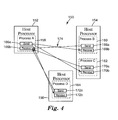
- FIG. 4 is a diagram of a portion of distributed computer system employing a reliable datagram service to communicate between distributed processes.
- FIG. 5 is a diagram of an example host processor node for operation in a distributed computer system.
- FIG. 6 is a diagram of a portion of a distributed computer system illustrating subnets in the distributed computer system.
- FIG. 7 is a diagram of a switch for use in a distributed computer system.
- FIG. 8 is a diagram of a portion of a distributed computer system.
- FIG. 9A is a diagram of a work queue element (WQE) for operation in the distributed computer system of FIG. 8.
- WQE work queue element
- FIG. 9B is a diagram of the packetization process of a message created by the WQE of FIG. 9A into frames and flits.
- FIG. 10A is a diagram of a message being transmitted with a reliable transport service illustrating frame transactions.
- FIG. 10B is a diagram illustrating a reliable transport service illustrating flit transactions associated with the frame transactions of FIG. 10A.
- FIG. 11 is a diagram of a layered architecture.
- FIG. 12 is a diagram illustrating a method for recognizing and managing network system congestion using congestion detection, reporting, and responding mechanisms.
- FIG. 13A is a simplified diagram illustrating one embodiment of a network system that includes an end station comprising an aggressive timer according to one embodiment of the present invention.
- FIG. 13B is a diagram illustrating an exemplary end station of FIG. 13A that includes an aggressive timer adapted to monitor the end station's port according to one embodiment of the present invention.
- FIG. 13C is a diagram of an exemplary end station of FIG. 13A that runs an application program according to one embodiment of the present invention.
- FIG. 13D is a diagram of an exemplary end station of FIG. 13A that includes a traffic congestion manager according to the present invention.
- FIG. 14 is a diagram of an example of one embodiment of a routing element having a network traffic congestion manager utilizing aggressive timers.
- FIG. 15 is a flow diagram illustrating an aggressive timer's and traffic congestion manager's operation in the exemplary routing element of FIG. 14.
- FIG. 16 is a diagram of one embodiment of an end station utilizing an aggressive timer and a forward progress timer.
- One aspect of the present invention is directed to a method and apparatus providing an aggressive timer-based congestion manager. This aspect facilitates the application of various criteria for selective treatment of frames based on frame or network system attributes as part of congestion detection, reporting, and/or response mechanisms.
- the congestion manager supports the enforcement of policies set by network fabric management.
- the congestion manager is employed on a network entity, including a network fabric element or end station, such as a switch, router, or endnode.
- FIG. 1 An example embodiment of a distributed computer system is illustrated generally at 30 in FIG. 1.
- Distributed computer system 30 is provided merely for illustrative purposes, and the embodiments of the present invention described below can be implemented on network systems of numerous other types and configurations.
- network systems implementing the present invention can range from a small server with one processor and a few input/output (I/O) adapters to massively parallel supercomputer systems with hundreds or thousands of processors and thousands of I/O adapters.
- I/O input/output
- the present invention can be implemented in an infrastructure of remote computer systems connected by an internet or intranet.
- Distributed computer system 30 includes a system area network (SAN) 32 which is a high-bandwidth, low-latency network interconnecting nodes within distributed computer system 30 .
- a node is herein defined to be any device attached to one or more links of a network and forming the origin and/or destination of messages within the network.
- nodes include host processors 34 a - 34 d; redundant array independent disk (RAID) subsystem 33 ; and I/O adapters 35 a and 35 b.
- the nodes illustrated in FIG. 1 are for illustrative purposes only, as SAN 32 can connect any number and any type of independent processor nodes, I/O adapter nodes, and I/O device nodes. Any one of the nodes can function as an endnode, which is herein defined to be a device that originates or finally consumes messages or frames in the distributed computer system.
- a message is herein defined to be an application-defined unit of data exchange, which is a primitive unit of communication between cooperating sequential processes.
- a frame is herein defined to be one unit of data encapsulated by a physical network protocol header and/or trailer.
- the header generally provides control and routing information for directing the frame through SAN 32 .
- the trailer generally contains control and cyclic redundancy check (CRC) data for ensuring frames are not delivered with corrupted contents.
- CRC cyclic redundancy check
- SAN 32 is the communications and management infrastructure supporting both I/O and interprocess communication (IPC) within distributed computer system 30 .
- SAN 32 includes a switched communications fabric (SAN FABRIC) allowing many devices to concurrently transfer data with high-bandwidth and low latency in a secure, remotely managed environment. Endnodes can communicate over multiple ports and utilize multiple paths 30 through the SAN fabric. The multiple ports and paths through SAN 32 can be employed for fault tolerance and increased bandwidth data transfers.
- SAN FABRIC switched communications fabric
- SAN 32 includes switches 36 and routers 38 .
- a switch is herein defined to be a device that connects multiple links 40 together and allows routing of frames from one link 40 to another link 40 within a subnet using a small header destination ID field.
- a router is herein defined to be a device that connects multiple links 40 together and is capable of routing frames from one link 40 in a first subnet to another link 40 in a second subnet using a large header destination address or source address.
- a link 40 is a full duplex channel between any two network fabric elements, such as endnodes, switches 36 , or routers 38 .
- Example suitable links 40 include, but are not limited to, copper cables, optical cables, and printed circuit copper traces on backplanes and printed circuit boards.
- Endnodes such as host processor endnodes 34 and I/O adapter endnodes 35 , generate request frames and return acknowledgment frames.
- switches 36 and routers 38 do not generate and consume frames.
- Switches 36 and routers 38 simply pass frames along. In the case of switches 36 , the frames are passed along unmodified. For routers 38 , the network header is modified slightly when the frame is routed. Endnodes, switches 36 , and routers 38 are collectively referred to as end stations.
- host processor nodes 34 a - 34 d and RAID subsystem node 33 include at least one system area network interface controller (SANIC) 42 .
- SANIC system area network interface controller
- each SANIC 42 is an endpoint that implements the SAN 32 interface in sufficient detail to source or sink frames transmitted on the SAN fabric.
- the SANICs 42 provide an interface to the host processors and I/O devices.
- the SANIC is implemented in hardware.
- the SANIC hardware offloads much of CPU and I/O adapter communication overhead.
- This hardware implementation of the SANIC also permits multiple concurrent communications over a switched network without the traditional overhead associated with communicating protocols.
- SAN 32 provides the I/O and IPC clients of distributed computer system 30 zero processor-copy data transfers without involving the operating system kernel process, and employs hardware to provide reliable, fault tolerant communications.
- router 38 is coupled to wide area network (WAN) and/or local area network (LAN) connections to other hosts or other routers 38 .
- WAN wide area network
- LAN local area network
- the host processors 34 a - 34 d include central processing units (CPUs) 44 and memory 46 .
- I/O adapters 35 a and 35 b include an I/O adapter backplane 48 and multiple I/O adapter cards 50 .
- Example adapter cards 50 illustrated in FIG. 1 include an SCSI adapter card; an adapter card to fiber channel hub and FC-AL devices; an Ethernet adapter card; and a graphics adapter card. Any known type of adapter card can be implemented.
- I/O adapters 35 a and 35 b also include a switch 36 in the I/O adapter backplane 48 to couple the adapter cards 50 to the SAN 32 fabric.
- RAID subsystem 33 includes a microprocessor 52 , memory 54 , read/write circuitry 56 , and multiple redundant storage disks 58 .
- SAN 32 handles data communications for I/O and IPC in distributed computer system 30 .
- SAN 32 supports high-bandwidth and scalability required for I/O and also supports the extremely low latency and low CPU overhead required for IPC.
- User clients can bypass the operating system kernel process and directly access network communication hardware, such as SANICs 42 which enable efficient message passing protocols.
- SAN 32 is suited to current computing models and is a building block for new forms of I/O and computer cluster communication.
- SAN 32 allows I/O adapter nodes to communicate among themselves or communicate with any or all of the processor nodes in distributed computer system 30 . With an I/O adapter attached to SAN 32 , the resulting I/O adapter node has substantially the same communication capability as any processor node in distributed computer system 30 .
- SAN 32 supports channel semantics and memory semantics.
- Channel semantics is sometimes referred to as send/receive or push communication operations, and is the type of communications employed in a traditional I/O channel where a source device pushes data and a destination device determines the final destination of the data.
- the frame transmitted from a source process specifies a destination processes' communication port, but does not specify where in the destination processes' memory space the frame will be written.
- the destination process pre-allocates where to place the transmitted data.
- a source process In memory semantics, a source process directly reads or writes the virtual address space of a remote node destination process. The remote destination process need only communicate the location of a buffer for data, and does not need to be involved with the transfer of any data. Thus, in memory semantics, a source process sends a data frame containing the destination buffer memory address of the destination process. In memory semantics, the destination process previously grants permission for the source process to access its memory.
- Channel semantics and memory semantics are typically both necessary for I/O and IPC.
- a typical I/O operation employs a combination of channel and memory semantics.
- host processor 34 a initiates an I/O operation by using channel semantics to send a disk write command to I/O adapter 35 b.
- I/O adapter 35 b examines the command and uses memory semantics to read the data buffer directly from the memory space of host processor 34 a. After the data buffer is read, I/O adapter 35 b employs channel semantics to push an I/O completion message back to host processor 34 a.
- distributed computer system 30 performs operations that employ virtual addresses and virtual memory protection mechanisms to ensure correct and proper access to all memory.
- applications running in distributed computed system 30 are not required to use physical addressing for any operations.
- Host processor node 34 includes a process A indicated at 60 and a process B indicated at 62 .
- Host processor node 34 includes SANIC 42 .
- Host processor node 34 also includes queue pairs (QPs) 64 a and 64 b which provide communication between process 60 and SANIC 42 .
- Host processor node 34 also includes QP 64 c which provides communication between process 62 and SANIC 42 .
- a single SANIC, such as SANIC 42 in a host processor 34 can support thousands of QPs.
- a SAN interface in an I/O adapter 35 typically supports less than ten QPs.
- Each QP 64 includes a send work queue 66 and a receive work queue 68 .
- a process such as processes 60 and 62 , calls an operating-system specific programming interface which is herein referred to as verbs, which place work items, referred to as work queue elements (WQEs) onto a QP 64 .
- WQE work queue elements
- a WQE is executed by hardware in SANIC 42 .
- SANIC 42 is coupled to SAN 32 via physical link 40 .
- Send work queue 66 contains WQEs that describe data to be transmitted on the SAN 32 fabric.
- Receive work queue 68 contains WQEs that describe where to place incoming data from the SAN 32 fabric.
- Host processor node 34 also includes completion queue 70 a interfacing with process 60 and completion queue 70 b interfacing with process 62 .
- the completion queues 70 contain information about completed WQEs.
- the completion queues are employed to create a single point of completion notification for multiple QPs.
- a completion queue entry is a data structure on a completion queue 70 that describes a completed WQE.
- the completion queue entry contains sufficient information to determine the QP that holds the completed WQE.
- a completion queue context is a block of information that contains pointers to, length, and other information needed to manage the individual completion queues.
- Example WQEs include work items that initiate data communications employing channel semantics or memory semantics; work items that are instructions to hardware in SANIC 42 to set or alter remote memory access protections; and work items to delay the execution of subsequent WQEs posted in the same send work queue 66 .
- example WQEs supported for send work queues 66 are as follows.
- a send buffer WQE is a channel semantic operation to push a local buffer to a remote QP's receive buffer.
- the send buffer WQE includes a gather list to combine several virtual contiguous local buffers into a single message that is pushed to a remote QP's receive buffer.
- the local buffer virtual addresses are in the address space of the process that created the local QP.
- a remote direct memory access (RDMA) read WQE provides a memory semantic operation to read a virtually contiguous buffer on a remote node.
- the RDMA read WQE reads a virtually contiguous buffer on a remote endnode and writes the data to a virtually contiguous local memory buffer.
- the local buffer for the RDMA read WQE is in the address space of the process that created the local QP.
- the remote buffer is in the virtual address space of the process owning the remote QP targeted by the RDMA read WQE.
- a RDMA write WQE provides a memory semantic operation to write a virtually contiguous buffer on a remote node.
- the RDMA write WQE contains a scatter list of locally virtually contiguous buffers and the virtual address of the remote buffer into which the local buffers are written.
- a RDMA FetchOp WQE provides a memory semantic operation to perform an atomic operation on a remote word.
- the RDMA FetchOp WQE is a combined RDMA read, modify, and RDMA write operation.
- the RDMA FetchOp WQE can support several read-modify-write operations, such as Compare and Swap if equal.
- a bind/unbind remote access key (RKey) WQE provides a command to SANIC hardware to modify the association of a RKey with a local virtually contiguous buffer.
- the RKey is part of each RDMA access and is used to validate that the remote process has permitted access to the buffer.
- a delay WQE provides a command to SANIC hardware to delay processing of the QP's WQEs for a specific time interval.
- the delay WQE permits a process to meter the flow of operations into the SAN fabric.
- receive work queues 68 only support one type of WQE, which is referred to as a receive buffer WQE.
- the receive buffer WQE provides a channel semantic operation describing a local buffer into which incoming send messages are written.
- the receive buffer WQE includes a scatter list describing several virtually contiguous local buffers. An incoming send message is written to these buffers.
- the buffer virtual addresses are in the address space of the process that created the local QP.
- a user-mode software process transfers data through QPs 64 directly from where the buffer resides in memory.
- the transfer through the QPs bypasses the operating system and consumes few host instruction cycles.
- QPs 64 permit zero processor-copy data transfer with no operating system kernel involvement. The zero processor-copy data transfer provides for efficient support of high-bandwidth and low-latency communication.
- the QP 64 When a QP 64 is created, the QP is set to provide a selected type of transport service.
- a distributed computer system implementing the present invention supports four types of transport services.
- FIG. 3 A portion of a distributed computer system employing a reliable connection service to communicate between distributed processes is illustrated generally at 100 in FIG. 3.
- Distributed computer system 100 includes a host processor node 102 , a host processor node 104 , and a host processor node 106 .
- Host processor node 102 includes a process A indicated at 108 .
- Host processor node 104 includes a process B indicated at 110 and a process C indicated at 112 .
- Host processor node 106 includes a process D indicated at 114 .
- Host processor node 102 includes a QP 116 having a send work queue 116 a and a receive work queue 116 b; a QP 118 having a send work queue 118 a and receive work queue 118 b; and a QP 120 having a send work queue 120 a and a receive work queue 120 b which facilitate communication to and from process A indicated at 108 .
- Host processor node 104 includes a QP 122 having a send work queue 122 a and receive work queue 122 b for facilitating communication to and from process B indicated at 110 .
- Host processor node 104 includes a QP 124 having a send work queue 124 a and receive work queue 124 b for facilitating communication to and from process C indicated at 112 .
- Host processor node 106 includes a QP 126 having a send work queue 126 a and receive work queue 126 b for facilitating communication to and from process D indicated at 114 .
- the reliable connection service of distributed computer system 100 associates a local QP with one and only one remote QP.
- QP 116 is connected to QP 122 via a non-sharable resource connection 128 having a non-sharable resource connection 128 a from send work queue 116 a to receive work queue 122 b and a non-sharable resource connection 128 b from send work queue 122 a to receive work queue 116 b.
- QP 118 is connected to QP 124 via a non-sharable resource connection 130 having a non-sharable resource connection 130 a from send work queue 118 a to receive work queue 124 b and a non-sharable resource connection 130 b from send work queue 124 a to receive work queue 118 b.
- QP 120 is connected to QP 126 via a non-sharable resource connection 132 having a non-sharable resource connection 132 a from send work queue 120 a to receive work queue 126 b and a non-sharable resource connection 132 b from send work queue 126 a to receive work queue 120 b.
- a send buffer WQE placed on one QP in a reliable connection service causes data to be written into the receive buffer of the connected QP.
- RDMA operations operate on the address space of the connected QP.
- the reliable connection service requires a process to create a QP for each process which is to communicate with over the SAN fabric.
- each host processor node contains M processes, and all M processes on each node wish to communicate with all the processes on all the other nodes, each host processor node requires M 2 ⁇ (N ⁇ 1) QPs.
- a process can connect a QP to another QP on the same SANIC.
- the reliable connection service is made reliable because hardware maintains sequence numbers and acknowledges all frame transfers. A combination of hardware and SAN driver software retries any failed communications. The process client of the QP obtains reliable communications even in the presence of bit errors, receive buffer underruns, and network congestion. If alternative paths exist in the SAN fabric, reliable communications can be maintained even in the presence of failures of fabric switches or links.
- acknowledgements are employed to deliver data reliably across the SAN fabric.
- the acknowledgement is not a process level acknowledgment, because the acknowledgment does not validate the receiving process has consumed the data. Rather, the acknowledgment only indicates that the data has reached its destination.
- FIG. 4 A portion of a distributed computer system employing a reliable datagram service to communicate between distributed processes is illustrated generally at 150 in FIG. 4.
- Distributed computer system 150 includes a host processor node 152 , a host processor node 154 , and a host processor node 156 .
- Host processor node 152 includes a process A indicated at 158 .
- Host processor node, 154 includes a process B indicated at 160 and a process C indicated at 162 .
- Host processor node 156 includes a process D indicated at 164 .
- Host processor node 152 includes QP 166 having send work queue 166 a and receive work queue 166 b for facilitating communication to and from process A indicated at 158 .
- Host processor node 154 includes QP 168 having send work queue 168 a and receive work queue 168 b for facilitating communication from and to process B indicated at 160 .
- Host processor node 154 includes QP 170 having send work queue 170 a and receive work queue 170 b for facilitating communication from and to process C indicated at 162 .
- Host processor node 156 includes QP 172 having send work queue 172 a and receive work queue 172 b for facilitating communication from and to process D indicated at 164 .
- the QPs are coupled in what is referred to as a connectionless transport service.
- a reliable datagram service 174 couples QP 166 to QPs 168 , 170 , and 172 .
- reliable datagram service 174 couples send work queue 166 a to receive work queues 168 b, 170 b, and 172 b.
- Reliable datagram service 174 also couples send work queues 168 a, 170 a, and 172 a to receive work queue 166 b.
- the reliable datagram service permits a client process of one QP to communicate with any other QP on any other remote node.
- the reliable datagram service permits incoming messages from any send work queue on any other remote node.
- the reliable datagram service employs sequence numbers and acknowledgments associated with each message frame to ensure the same degree of reliability as the reliable connection service.
- End-to-end (EE) contexts maintain end-to-end specific state to keep track of sequence numbers, acknowledgments, and time-out values.
- the end-to-end state held in the EE contexts is shared by all the connectionless QPs communicating between a pair of endnodes.
- Each endnode requires at least one EE context for every endnode it wishes to communicate with in the reliable datagram service (e.g., a given endnode requires at least N EE contexts to be able to have reliable datagram service with N other endnodes).
- the reliable datagram service greatly improves scalability because the reliable datagram service is connectionless. Therefore, an endnode with a fixed number of QPs can communicate with far more processes and endnodes with a reliable datagram service than with a reliable connection transport service. For example, if each of N host processor nodes contain M processes, and all M processes on each node wish to communicate with all the processes on all the other nodes, the reliable connection service requires M 2 ⁇ (N ⁇ 1) QPs on each node. By comparison, the connectionless reliable datagram service only requires M QPs+(N ⁇ 1) EE contexts on each node for exactly the same communications.
- a third type of transport service for providing communications is a unreliable datagram service. Similar to the reliable datagram service, the unreliable datagram service is connectionless. The unreliable datagram service is employed by management applications to discover and integrate new switches, routers, and endnodes into a given distributed computer system. The unreliable datagram service does not provide the reliability guarantees of the reliable connection service and the reliable datagram service. The unreliable datagram service accordingly operates with less state information maintained at each endnode.
- a fourth type of transport service is referred to as raw datagram service and is technically not a transport service.
- the raw datagram service permits a QP to send and to receive raw datagram frames.
- the raw datagram mode of operation of a QP is entirely controlled by software.
- the raw datagram mode of the QP is primarily intended to allow easy interfacing with traditional internet protocol, version 6 (IPv6) LAN-WAN networks, and further allows the SANIC to be used with full software protocol stacks to access transmission control protocol (TCP), user datagram protocol (UDP), and other standard communication protocols.
- TCP transmission control protocol
- UDP user datagram protocol
- SANIC hardware generates and consumes standard protocols layered on top of IPv6, such as TCP and UDP.
- the frame header can be mapped directly to and from an IPv6 header.
- Native IPv6 frames can be bridged into the SAN fabric and delivered directly to a QP to allow a client process to support any transport protocol running on top of IPv6.
- a client process can register with SANIC hardware in order to direct datagrams for a particular upper level protocol (e.g., TCP and UDP) to a particular QP.
- SANIC hardware can demultiplex incoming IPv6 streams of datagrams based on a next header field as well as the destination IP address.
- Host processor node 200 includes a process A indicated at 202 , a process B indicated at 204 , and a process C indicated at 206 .
- Host processor 200 includes a SANIC 208 and a SANIC 210 .
- SANIC 208 includes a SAN link level engine (LLE) 216 for communicating with SAN fabric 224 via link 217 and an LLE 218 for communicating with SAN fabric 224 via link 219 .
- LLE SAN link level engine
- SANIC 210 includes an LLE 220 for communicating with SAN fabric 224 via link 221 and an LLE 222 for communicating with SAN fabric 224 via link 223 .
- SANIC 208 communicates with process A indicated at 202 via QPs 212 a and 212 b.
- SANIC 208 communicates with process B indicated at 204 via QPs 212 c - 212 n.
- SANIC 208 includes N QPs for communicating with processes A and B.
- SANIC 210 includes QPs 214 a and 214 b for communicating with process B indicated at 204 .
- SANIC 210 includes QPs 214 c - 214 n for communicating with process C indicated at 206 .
- SANIC 210 includes N QPs for communicating with processes B and C.
- An LLE runs link level protocols to couple a given SANIC to the SAN fabric.
- RDMA traffic generated by a SANIC can simultaneously employ multiple LLEs within the SANIC which permits striping across LLEs.
- Striping refers to the dynamic sending of frames within a single message to an endnode's QP through multiple fabric paths. Striping across LLEs increases the bandwidth for a single QP as well as provides multiple fault tolerant paths. Striping also decreases the latency for message transfers.
- multiple LLEs in a SANIC are not visible to the client process generating message requests. When a host processor includes multiple SANICs, the client process must explicitly move data on the two SANICs in order to gain parallelism.
- a single QP cannot be shared by SANICS. Instead a QP is owned by one local SANIC.
- a host name provides a logical identification for a host node, such as a host processor node or I/O adapter node.
- the host name identifies the endpoint for messages such that messages are destine for processes residing on an endnode specified by the host name.
- SANICs SANICs
- GUID globally unique ID
- a local ID refers to a short address ID used to identify a SANIC within a single subnet.
- a subnet has up 2 16 endnodes, switches, and routers, and the local ID (LID) is accordingly 16 bits.
- a source LID (SLID) and a destination LID (DLID) are the source and destination LIDs used in a local network header.
- a LLE has a single LID associated with the LLE, and the LID is only unique within a given subnet. One or more LIDs can be associated with each SANIC.
- IP address (e.g., a 128 bit IPv6 ID) addresses a SANIC.
- the SANIC can have one or more IP addresses associated with the SANIC.
- the IP address is used in the global network header when routing frames outside of a given subnet.
- LIDs and IP addresses are network endpoints and are the target of frames routed through the SAN fabric. All IP addresses (e.g., IPv6 addresses) within a subnet share a common set of high order address bits.
- the LLE is not named and is not architecturally visible to a client process.
- management software refers to LLEs as an enumerated subset of the SANIC.
- a portion of a distributed computer system is generally illustrated at 250 in/FIG. 6.
- Distributed computer system 250 includes a subnet A indicated at 252 and a subnet B indicated at 254 .
- Subnet A indicated at 252 includes a host processor node 256 and a host processor node 258 .
- Subnet B indicated at 254 includes a host processor node 260 and host processor node 262 .
- Subnet A indicated at 252 includes switches 264 a - 264 c.
- Subnet B indicated at 254 includes switches 266 a - 266 c.
- Each subnet within distributed computer system 250 is connected to other subnets with routers.
- subnet A indicated at 252 includes routers 268 a and 268 b which are coupled to routers 270 a and 270 b of subnet B indicated at 254 .
- a subnet has up to 2 16 endnodes, switches, and routers.
- a subnet is defined as a group of endnodes and cascaded switches that is managed as a single unit. Typically, a subnet occupies a single geographic or functional area. For example, a single computer system in one room could be defined as a subnet. In one embodiment, the switches in a subnet can perform very fast worm-hole or cut-through routing for messages.
- a switch within a subnet examines the DLID that is unique within the subnet to permit the switch to quickly and efficiently route incoming message frames.
- the switch is a relatively simple circuit, and is typically implemented as a single integrated circuit.
- a subnet can have hundreds to thousands of endnodes formed by cascaded switches.
- IP destination ID e.g., IPv6 destination ID
- switches and routers degrade when links are over utilized.
- link level back pressure is used to temporarily slow the flow of data when multiple input frames compete for a common output.
- link or buffer contention does not cause loss of data.
- switches, routers, and endnodes employ a link protocol to transfer data.
- the link protocol supports an automatic error retry.
- link level acknowledgments detect errors and force retransmission of any data impacted by bit errors.
- Link-level error recovery greatly reduces the number of data errors that are handled by the end-to-end protocols.
- the user client process is not involved with error recovery no matter if the error is detected and corrected by the link level protocol or the end-to-end protocol.
- FIG. 7 An example embodiment of a switch is generally illustrated at 280 in FIG. 7.
- Each I/O path on a switch or router has an LLE.
- switch 280 includes LLEs 282 a - 282 h for communicating respectively with links 284 a - 284 h.
- the naming scheme for switches and routers is similar to the above-described naming scheme for endnodes.
- the following is an example switch and router naming scheme for identifying switches and routers in the SAN fabric.
- a switch name identifies each switch or group of switches packaged and managed together. Thus, there is a single switch name for each switch or group of switches packaged and managed together.
- Each switch or router element has a single unique GUID.
- Each switch has one or more LIDs and IP addresses (e.g., IPv6 addresses) that are used as an endnode for management frames.
- Each LLE is not given an explicit external name in the switch or router. Since links are point-to-point, the other end of the link does not need to address the LLE.
- Switches and routers employ multiple virtual lanes within a single physical link. As illustrated in FIG. 6, physical links 272 connect endnodes, switches, and routers within a subnet. WAN or LAN connections 274 typically couple routers between subnets. Frames injected into the SAN fabric follow a particular virtual lane from the frame's source to the frame's destination. At any one time, only one virtual lane makes progress on a given physical link. Virtual lanes provide a technique for applying link level flow control to one virtual lane without affecting the other virtual lanes. When a frame on one virtual lane blocks due to contention, quality of service (QoS), or other considerations, a frame on a different virtual lane is allowed to make progress.
- QoS quality of service
- Virtual lanes are employed for numerous reasons, some of which are as follows. Virtual lanes provide QoS. In one example embodiment, certain virtual lanes are reserved for high priority or isonchronous traffic to provide QoS.
- Virtual lanes provide deadlock avoidance. Virtual lanes allow topologies that contain loops to send frames across all physical links and still be assured the loops won't cause back pressure dependencies that might result in deadlock.
- Virtual lanes alleviate head-of-line blocking. With virtual lanes, a blocked frames can pass a temporarily stalled frame that is destined for a different final destination.
- each switch includes its own crossbar switch.
- a switch propagates data from only one frame at a time, per virtual lane through its crossbar switch.
- a switch propagates a single frame from start to finish.
- frames are not multiplexed together on a single virtual lane.
- a path from a source port to a destination port is determined by the LID of the destination SANIC port. Between subnets, a path is determined by the IP address (e.g., IPv6 address) of the destination SANIC port.
- IP address e.g., IPv6 address
- the paths used by the request frame and the request frame's corresponding positive acknowledgment (ACK) or negative acknowledgment (NAK) frame are not required to be symmetric.
- switches select an output port based on the DLID.
- a switch uses one set of routing decision criteria for all its input ports.
- the routing decision criteria is contained in one routing table.
- a switch employs a separate set of criteria for each input port.
- Each port on an endnode can have multiple IP addresses. Multiple IP addresses can be used for several reasons, some of which are provided by the following examples. In one embodiment, different IP addresses identify different partitions or services on an endnode. In one embodiment, different IP addresses are used to specify different QoS attributes. In one embodiment, different IP addresses identify different paths through intra-subnet routes.
- each port on an endnode can have multiple LIDs. Multiple LIDs can be used for several reasons some of which are provided by the following examples. In one embodiment, different LIDs identify different partitions or services on an endnode. In one embodiment, different LIDs are used to specify different QoS attributes. In one embodiment, different LIDs specify different paths through the subnet.
- a one-to-one correspondence does not necessarily exist between LIDs and IP addresses, because a SANIC can have more or less LIDs than IP addresses for each port.
- SANICs can, but are not required to, use the same LID and IP address on each of its ports.
- a data transaction in distributed computer system 30 is typically composed of several hardware and software steps.
- a client process of a data transport service can be a user-mode or a kernel-mode process.
- the client process accesses SANIC 42 hardware through one or more QPs, such as QPs 64 illustrated in FIG. 2.
- QPs 64 illustrated in FIG. 2.
- the client process calls an operating-system specific programming interface which is herein referred to as verbs.
- the software code implementing the verbs intern posts a WQE to the given QP work queue.
- SANIC hardware detects WQE posting and accesses the WQE.
- the SANIC hardware translates and validates the WQEs virtual addresses and accesses the data.
- an outgoing message buffer is split into one or more frames.
- the SANIC hardware adds a transport header and a network header to each frame.
- the transport header includes sequence numbers and other transport information.
- the network header includes the destination IP address or the DLID or other suitable destination address information. The appropriate local or global network header is added to a given frame depending on if the destination endnode resides on the local subnet or on a remote subnet.
- a frame is a unit of information that is routed through the SAN fabric.
- the frame is an endnode-to-endnode construct, and is thus created and consumed by endnodes.
- Switches and routers neither generate nor consume request frames or acknowledgment frames. Instead switches and routers simply move request frames or acknowledgment frames closer to the ultimate destination. Routers, however, modify the frame's network header when the frame crosses a subnet boundary. In traversing a subnet, a single frame stays on a single virtual lane.
- a flit is herein defined to be a unit of link-level flow control and is a unit of transfer employed only on a point-to-point link.
- the flow of flits is subject to the link-level protocol which can perform flow control or retransmission after an error.
- flit is a link-level construct that is created at each endnode, switch, or router output port and consumed at each input port.
- a flit contains a header with virtual lane error checking information, size information, and reverse channel credit information.
- the destination endnode sends an acknowledgment frame back to the sender endnode.
- the acknowledgment frame permits the requester to validate that the request frame reached the destination endnode.
- An acknowledgment frame is sent back to the requester after each request frame.
- the requestor can have multiple outstanding requests before it receives any acknowledgments. In one embodiment, the number of multiple outstanding requests is determined when a QP is created.
- FIG. 8 a portion of a distributed computer system is generally illustrated at 300 .
- Distributed computer system 300 includes a host processor node 302 and a host processor node 304 .
- Host processor node 302 includes a SANIC 306 .
- Host processor node 304 includes a SANIC 308 .
- Distributed computer system 300 includes a SAN fabric 309 which includes a switch 310 and a switch 312 .
- SAN fabric 309 includes a link 314 coupling SANIC 306 to switch 310 ; a link 316 coupling switch 310 to switch 312 ; and a link 318 coupling SANIC 308 to switch 312 .
- host processor node 302 includes a client process A indicated at 320 .
- Host processor node 304 includes a client process B indicated at 322 .
- Client process 320 interacts with SANIC hardware 306 through QP 324 .
- Client process 322 interacts with SANIC hardware 308 through QP 326 .
- QP 324 and 326 are software data structures.
- QP 324 includes send work queue 324 a and receive work queue 324 b.
- QP 326 includes send work queue 326 a and receive work queue 326 b.
- Process 320 initiates a message request by posting WQEs to send work queue 324 a. Such a WQE is illustrated at 330 in FIG. 9A.
- the message request of client process 320 is referenced by a gather list 332 contained in send WQE 330 .
- Each entry in gather list 332 points to a virtually contiguous buffer in the local memory space containing a part of the message, such as indicated by virtual contiguous buffers 334 a - 334 d, which respectively hold message 0, parts 0, 1, 2, and 3.
- frame 0 indicated at 336 a is partitioned into flits 0-3, indicated respectively at 342 a - 342 d.
- Frame 1 indicated at 336 b is partitioned into flits 4-7 indicated respectively at 342 e - 342 h.
- Flits 342 a through 342 h respectively include flit headers 344 a - 344 h.
- Frames are routed through the SAN fabric, and for reliable transfer services, are acknowledged by the final destination endnode. If not successfully acknowledged, the frame is retransmitted by the source endnode. Frames are generated by source endnodes and consumed by destination endnodes. The switches and routers in the SAN fabric neither generate nor consume frames.
- Flits are the smallest unit of flow control in the network. Flits are generated and consumed at each end of a physical link. Flits are acknowledged at the receiving end of each link and are retransmitted in response to an error. For example, controlling retransmission or abortion of flit transmission can be accomplished with each sender maintaining a per-port link retry timer to monitor the time between flit transmission and receipt acknowledgment. If the link retry timer expires, the sender attempts to retry transmission of the outstanding flit. A second timer, called a link kill timer, is active while the sender is operating in a retry mode. On expiration of the link kill timer, transmission is aborted.
- a link kill timer is active while the sender is operating in a retry mode.
- the send request message 0 is transmitted from SANIC 306 in host processor node 302 to SANIC 308 in host processor node 304 as frames 0 indicated at 336 a and frame 1 indicated at 336 b.
- ACK frames 346 a and 346 b are transmitted from SANIC 308 in host processor node 304 to SANIC 306 in host processor node 302 .
- message 0 is being transmitted with a reliable transport service.
- Each request frame is individually acknowledged by the destination endnode (e.g., SANIC 308 in host processor node 304 ).
- FIG. 10B illustrates the flits associated with the request frames 336 and acknowledgment frames 346 illustrated in FIG. 10A passing between the host processor endnodes 302 and 304 and the switches 310 and 312 .
- an ACK frame fits inside one flit.
- one acknowledgment flit acknowledges several flits.
- flits 342 a - h are transmitted from SANIC 306 to switch 310 .
- Switch 310 consumes flits 342 a - h at its input port, creates flits 348 a - h at its output port corresponding to flits 342 a - h, and transmits flits 348 a - h to switch 312 .
- Switch 312 consumes flits 348 a - h at its input port, creates flits 350 a - h at its output port corresponding to flits 348 a - h, and transmits flits 350 a - h to SANIC 308 .
- SANIC 308 consumes flits 350 a - h at its input port.
- An acknowledgment flit is transmitted from switch 310 to SANIC 306 to acknowledge the receipt of flits 342 a - h.
- An acknowledgment flit 354 is transmitted from switch 312 to switch 310 to acknowledge the receipt of flits 348 a - h.
- An acknowledgment flit 356 is transmitted from SANIC 308 to switch 312 to acknowledge the receipt of flits 350 a - h.
- Acknowledgment frame 346 a fits inside of flit 358 which is transmitted from SANIC 308 to switch 312 .
- Switch 312 consumes flits 358 at its input port, creates flit 360 corresponding to flit 358 at its output port, and transmits flit 360 to switch 310 .
- Switch 310 consumes flit 360 at its input port, creates flit 362 corresponding to flit 360 at its output port, and transmits flit 362 to SANIC 306 .
- SANIC 306 consumes flit 362 at its input port.
- SANIC 308 transmits acknowledgment frame 346 b in flit 364 to switch 312 .
- Switch 312 creates flit 366 corresponding to flit 364 , and transmits flit 366 to switch 310 .
- Switch 310 creates flit 368 corresponding to flit 366 , and transmits flit 368 to SANIC 306 .
- Switch 312 acknowledges the receipt of flits 358 and 364 with acknowledgment flit 370 , which is transmitted from switch 312 to SANIC 308 .
- Switch 310 acknowledges the receipt of flits 360 and 366 with acknowledgment flit 372 , which is transmitted to switch 312 .
- SANIC 306 acknowledges the receipt of flits 362 and 368 with acknowledgment flit 374 which is transmitted to switch 310 .
- a host processor endnode and an I/O adapter endnode typically have quite different capabilities.
- an example host processor endnode might support four ports, hundreds to thousands of QPs, and allow incoming RDMA operations
- an attached I/O adapter endnode might only support one or two ports, tens of QPs, and not allow incoming RDMA operations.
- a low-end attached I/O adapter alternatively can employ software to handle much of the network and transport layer functionality which is performed in hardware (e.g., by SANIC hardware) at the host processor endnode.
- FIG. 11 One embodiment of a layered architecture for implementing the present invention is generally illustrated at 400 in diagram form in FIG. 11.
- the layered architecture diagram of FIG. 11 shows the various layers of data communication paths, and organization of data and control information passed between layers.
- Host SANIC endnode layers are generally indicated at 402 .
- the host SANIC endnode layers 402 include an upper layer protocol 404 ; a transport layer 406 ; a network layer 408 ; a link layer 410 ; and a physical layer 412 .
- Switch or router layers are generally indicated at 414 .
- Switch or router layers 414 include a network layer 416 ; a link layer 418 ; and a physical layer 420 .
- I/O adapter endnode layers are generally indicated at 422 .
- I/O adapter endnode layers 422 include an upper layer protocol 424 ; a transport layer 426 ; a network layer 428 ; a link layer 430 ; and a physical layer 432 .
- the layered architecture 400 generally follows an outline of a classical communication stack.
- the upper layer protocols employ verbs to create messages at the transport layers.
- the transport layers pass messages to the network layers.
- the network layers pass frames down to the link layers.
- the link layers pass flits through physical layers.
- the physical layers send bits or groups of bits to other physical layers.
- the link layers pass flits to other link layers, and don't have visibility to how the physical layer bit transmission is actually accomplished.
- the network layers only handle frame routing, without visibility to segmentation and reassembly of frames into flits or transmission between link layers.
- Links 434 can be implemented with printed circuit copper traces, copper cable, optical cable, or with other suitable links.
- the upper layer protocol layers are applications or processes which employ the other layers for communicating between endnodes.
- the transport layers provide end-to-end message movement.
- the transport layers provide four types of transport services as described above which are reliable connection service; reliable datagram service; unreliable datagram service; and raw datagram service.
- the network layers perform frame routing through a subnet or multiple subnets to destination endnodes.
- the link layers perform flow-controlled, error controlled, and prioritized frame delivery across links.
- the physical layers perform technology-dependent bit transmission and reassembly into flits.
- FIG. 12 An example embodiment of a method for recognizing and managing network system congestion using congestion detection, reporting, and responding mechanisms is illustrated in FIG. 12.
- the method involves monitoring network traffic conditions for signs of inefficiency, or network bandwidth underutilization.
- monitored network conditions 436 are tested for the presence of certain conditions indicative of delayed frame transmission progress, defined at 437 .
- the result of the testing at 435 is indicated at 438 .
- the duration of monitored conditions 436 is timed and compared to a configured timing threshold 440 .
- an indication is provided if, at 439 , the measured duration of monitored conditions 436 exceeds configured timing threshold 440 .
- a response 442 is made based on indication 441 and on response configuration 443 .
- measurement mechanism 439 is implemented in a network end station, such as an end node or routing device, that includes one or more aggressive timers for indicating a delay in frame transmission.
- An aggressive timer is herein defined as a timing device or mechanism that monitors the transmission of information in a network system or network system element, and can be configured to provide an indication of whether and when the transmission of information fails to meet at least one variable timing threshold.
- An aggressive timer can be implemented in hardware or software.
- Network system 449 includes an end station 450 comprising aggressive timer 452 .
- End station 450 interfaces with other end stations of SAN 451 through links 484 a and 484 b.
- Network traffic internal to end station 450 is indicated at 454 .
- Aggressive timer 452 monitors network traffic 454 via a monitoring mechanism 456 .
- Aggressive timer 452 's variable timing threshold is configurable and re-configurable as a function of network system attributes, as indicated at 453 .
- An attribute of an entity is herein defined as including, but not limited to, at least one aspect, characteristic, condition, configuration, essence, parameter, property, quality, setting, or status, of the entity to which it refers.
- Aggressive timer 452 sufficiently monitors network traffic to permit its variable timing threshold to be configured to detect or anticipate the onset of congestion.
- Aggressive timer 452 's variable timing threshold is configurable and re-configurable to accommodate different network circumstances, such as variations in network system attributes, including frame attributes and operating conditions within the network system.
- the variable timing threshold of the aggressive timer 452 refers to a duration of time against which one or more defined conditions of delayed frame transmission progress can be compared.
- the conditions of delayed frame transmission progress can be defined in a number of ways according to network traffic management policy. For example, in one embodiment, an expiration of a link retry timer is a condition of delayed frame transmission progress.
- the variable timing threshold is varied from one configuration to another by setting a starting count, ending count and/or counting rate. In one embodiment, the variable timing threshold is varied by adjusting a timing interval having a configurable ending time relative to a starting time. In one embodiment, the variable timing threshold is configurable to enable or disable the aggressive timer. When the variable timing threshold is exceeded, numerous suitable responses can be taken as part of enforcing a congestion management policy.
- FIG. 13B illustrates an exemplary end station 450 according to one embodiment of the present invention, which includes an aggressive timer 452 .
- the Aggressive timer 452 is adapted to monitor one or more ports 455 of end station 450 .
- aggressive timer 452 measures whether the transmission of a frame has stalled for a time that exceeds the variable timing threshold.
- a variable timing threshold's duration is only slightly longer than the time needed for transmitting a given frame out of a port 455 under normal operating conditions. Such a short time limit facilitates fast recognition of transmission delay, which permits anticipation of network congestion.
- the aggressive timer has microsecond granularity.
- aggressive timer 452 is implemented in end station 450 as a count-down timer set to a specific counting value and counting rate, which together, represent the configured variable timing threshold.
- count down aggressive timer 452 counts down during one or more defined conditions of delayed frame transmission progress, such as a period of transmission delay associated with a port 455 .
- the frame transmission delay is defined by an indication of the output frame's failure to make forward progress. If the frame makes forward progress, count-down aggressive timer 452 is reset.
- the count-down aggressive timer 452 is set to count while any part of a frame remains in a transmit register, regardless of forward progress status.
- variable timing threshold is configured by an appropriate authority, such as network fabric management.
- variable timing threshold is dynamically configurable, either manually or by program, based on potentially changing circumstances or decision-making criteria relating to the network system. Examples of potentially changing network circumstances include network system attributes, such as a congestion level of an end station's port, a policy for managing network congestion, or various attributes of a frame to be transmitted.
- An exemplary potentially changing decision-making criteria relating to the network system is a congestion management policy instituted by network fabric management.
- Network circumstances and decision-making criteria can also be interrelated, such that a congestion management policy, for example, can change in response to changing network system conditions.
- the dynamic characteristics of embodiments of the present invention can be employed to implement potentially changing network decision-making criteria, measuring potentially changing network circumstances, or both.
- One embodiment of aggressive timer 452 is configurable based on one or more network system attributes.
- configuration of the variable timing threshold can be made based on one or more predetermined network system attributes and/or based on measured network system status.
- Predetermined network system attributes herein refers to information characterizing at least one aspect of the network system and its contents that was determined at some time before the period surrounding the setting of the variable timing threshold, or over a period of time prior to, and potentially including, the decision-making period.
- Measured network system status refers to at least one aspect of the network system and its contents that is determined in the period surrounding the setting of the variable timing threshold.
- the variable timing threshold can be dynamically configurable in embodiments of aggressive timer 452 having a variable timing threshold based on predetermined or measured network system attributes.
- aggressive timer 452 is configurable based on one or more attributes of at least one port 455 .
- the aggressive timer 452 's variable timing threshold is adjustable as a function of a measured presence of back pressure from a port.
- Back pressure herein refers to network operation that is indicative of insufficient buffer space.
- the variable timing threshold is based on historical data of a port's back pressure occurrences over a period of time. In one example operation of end station 450 of FIG. 13B, port 455 a tends to be congested, and end station 450 accordingly institutes a more stringent variable timing threshold for congestion management.
- variable timing threshold is configurable based on the type of workload of applications utilizing the network system.
- FIG. 13C illustrates an end station 450 , which runs an application 458 .
- Aggressive timer 452 's variable timing threshold is configurable based on the type of workload of application 458 .
- Workload herein refers to the information exchanged over the network for a given application.
- Example types of workloads include digital video information for video applications, and file transfer protocol (FTP). Since video workloads are less tolerant of inconsistent transmission rates, an exemplary congestion management policy can impose variable timing thresholds with shorter limits for video applications than for web page browsing applications.
- a network system which predominately carries video application data comprises end stations 450 with aggressive timers 452 configured with stringent variable timing thresholds for early detection and prevention of congestion.
- variable timing threshold is configurable based on an amount of time one or more frames fails to make forward progress.
- end station 450 employs aggressive timer 452 to measure congestion experienced by a first frame targeting a particular port 455 .
- the aggressive timer 452 is set to expire after a time period that is approximately the time needed to transmit the first frame to its targeted port 455 in the absence of congestion.
- end station 450 is further configured to track the number of frame delay indications of aggressive timer 452 , as applied to the first frame. If the frame is delayed due to congestion, aggressive timer 452 provides at least one frame delay indication.
- the tracked number of frame delay indications represents an amount of time during which the frame fails to make forward progress.
- the variable timing threshold for identifying a level of congestion that requires a response is represented by a number of aggressive timer 452 expirations.
- the variable timing threshold for a second frame targeting the same port 455 can be adjusted based on the number.
- the variable timing threshold is configurable based on the type of network system architecture.
- an end station 450 transmitting a frame employs predetermined information about at least one end station along the frame's intended transmission path to configure the variable timing threshold for the frame.
- the predetermined information includes the at least one end station's role in overall system performance. For example, if a first frame's routing path includes a switch that is a major network hub and potential bottleneck, the variable timing threshold for the first frame can be set to be more stringent.
- variable timing threshold is configurable based on historical data of the congestion status of the end stations along a frame's routing path. In another embodiment, the variable timing threshold is based on a measured congestion status of an end station along the routing path. In another embodiment, the variable timer threshold is configurable based on a predetermined or measured transmission bandwidth of at least one downstream end station. The bandwidth might be restricted due to the end stations' capacity or congestion status. In an example of such an embodiment, a variable timing threshold of an aggressive timer 452 used with a port 455 is a function of the associated link hop speed.
- variable timing threshold is based on a frame attribute.
- the frame upon which the threshold is based is examined to ascertain its relevant attributes.
- the end station 450 includes a hardware or software mechanism for examining a frame's protocol header and/or trailer.
- the variable timing threshold is based on the size of a frame.
- the aggressive timer 452 is configured to a limit that is proportional to the size of the frame in the transmit register of port 455 . A limit that is only slightly greater than the time for transmitting the frame, provides a high sensitivity for detecting transmission delay.
- variable timing threshold is configurable based on the output frame's information type, such as whether the frame carries data or control information.
- the information type is determined using a mechanism for parsing out a message's opcode.
- control frames can be given a higher or lower priority of service than data-bearing frames, such that the aggressive timer 452 is configured to allow higher priority frames more time to make forward progress before a congestion management response is taken with respect to the frames.
- the variable timing threshold is dynamically configurable based on a frame's source or destination end station.
- the aggressive timer 452 is configured based on the frame's final destination end station.
- the end station 450 transmitting the frame examines the frame to determine its final destination, and configures the variable timing threshold of aggressive timer 452 accordingly.
- a frame addressed to an inherently slower device such as a disk drive
- a more stringent timing threshold i.e., a shorter time limit
- the transmitting end station 450 has a mechanism to recognize the final destination end station type with respect to its role on system performance. Therefore, an exemplary transmitting end station, utilizing aggressive timing configured based on final frame destination, can enforce a priority policy that gives service precedence to frames destined for end station types that have more time-critical roles.
- variable timing threshold is based on the source end station of a given frame.
- Network system policy may have assigned a higher or lower priority for frames originating from particular end nodes.
- an exemplary transmitting end station 450 along the frame's routing path examines the frame header to determine the originating end node, looks up the variable timing threshold for the end node, and applies the variable timing threshold as a time limit for the aggressive timer 452 .
- variable timing threshold for an aggressive timer is configurable based on one or more frame attributes
- the frame being transported is examined for its group identification, which is indicative of the type of communication service of the frame.
- Example communication service types include, but are not limited to: multicasting, unicasting, and broadcasting.
- An exemplary embodiment of this type implements one or more policies for congestion management or priority servicing, where the policy dictates various priorities for respective communication services.
- the variable timing threshold is applied frame-by-frame according to each frame's communication service. For example, in a network system where a policy provides higher priority to multicast transmissions, end stations 450 along a routing path for a given multicast frame, apply less stringent timing thresholds (longer aggressive timer limits) to the multicast frame.
- variable timing threshold is configurable based on a frame's assigned service level.
- the end station 450 examines the frame to be transmitted to determine its service level flag values.
- the variable timing threshold is configured to be more or less stringent.
- an aggressive timing limit for a low-priority frame is set to a lower, more stringent level, to cause the low-priority frame to not be transmitted in favor of preserving transmission bandwidth for higher-priority frames.
- an exemplary end station 450 Upon expiration of the aggressive timer 452 , an exemplary end station 450 takes one or more actions in response thereto.
- the end station 450 includes a traffic congestion manager 460 for responding to the aggressive timer 452 's indication of its expiration.
- Traffic congestion manager 460 's response is denoted at 462 ; aggressive timer 452 's indication is denoted at 464 .
- the traffic congestion manager 460 can be realized in hardware or software.
- a traffic congestion manager and at least one aggressive timer are realized as a single functional unit 466 , which performs the functions of both the aggressive timer and traffic congestion manager.
- the traffic congestion manager 460 is configurable to respond to the aggressive timer 452 's indication in a number of ways. In one such embodiment, the traffic congestion manager responds to an expiration of the aggressive timer 452 by dropping at least one frame. In one exemplary embodiment, the traffic congestion manager 460 drops the frame currently being transmitted. In another exemplary embodiment, the traffic congestion manager 460 drops frames randomly, or by a weighted random algorithm. In another exemplary embodiment, the traffic congestion manager 460 drops one or more frames in a port's transmission buffer based on the frames' attributes.
- traffic congestion manager 460 drops all frames in the output buffer targeting the same intermediate or final destination end station that the current frame targets when the aggressive timer 452 measuring the current frame's transmission progress expires.
- the traffic congestion manager 460 clears the entire transmit buffer of the port in response to aggressive timer 452 's expiration.
- the frame dropping is performed over a certain period of time in order to affect future frames as well as the current frame.
- congestion manager 460 upon expiration of the aggressive timer 452 , congestion manager 460 truncates the current frame by discarding the frame's untransmitted flits.
- the traffic congestion manager 460 responds to an expiration of aggressive timer 452 by generating one or more reporting frames to be used by one or more end stations or fabric management for congestion management purposes.
- An exemplary reporting frame includes data characterizing the nature of the aggressive timer's expiration, or circumstances surrounding the aggressive timer's expiration.
- the reporting frame has data containing information about the delayed frame during the transmission of which the aggressive timer 452 expired, such as the frame's size, destination, or service level.
- the traffic congestion manager 460 responds to aggressive timer 452 's expiration by tagging the current frame with information indicative of the congestion experienced by the frame.
- the current frame and all subsequent frames thereto are tagged for a period of time. Tagging can thus be used as a means for communicating traffic congestion information to other end stations in the network.
- the other end stations can include fabric management agents, neighboring routing elements, and source endnodes.
- the traffic congestion manager 460 responds to the aggressive timer 452 's expiration by logging the expiration occurrence and its surrounding circumstances.
- traffic congestion manager 460 maintains a log of aggressive timer 452 expirations, wherein the log contains information useful for characterizing the end station 450 's congestion status over a period time. In one embodiment, this characterization is employed to re-configure at least one aggressive timer 452 's variable timing threshold.
- the traffic congestion manager 460 is dynamically configurable.
- the response to the aggressive timer 452 is selectable by network system or fabric management.
- the response is dynamically configurable based on predetermined or measured changing circumstances, as described above for the dynamically configurable aggressive timer.
- the response 462 is configurable based on one or more frame delay indications 464 provided by the aggressive timer 452 .
- the aggressive timer is configured to indicate multiple levels of delay (such as with a plurality of frame transmission delay indications)
- the traffic congestion manager 460 can take different responses as the frame delay continues.
- the responses 462 can progressively increase in their efficacy as a measured delay becomes longer.
- the initial response 462 is a type of event logging; the next response 462 is communication of congestion status (such as frame tagging or sending congestion management packets); the next response 462 is a type of selective frame dropping; finally, the most drastic response 462 to aggressive timer expiration is a flushing of all buffered frames for a period of time.
- FIG. 14 illustrates an exemplary routing element 500 interfacing with SAN fabric 509 through a link indicated generally at 584 .
- Routing element 500 includes ports 502 a, 502 b and 502 c. Ports 502 connect via links 584 a, 584 b and 584 c, respectively, with SAN fabric 509 .
- Each port 502 has a receive register 504 and transmit queue 506 .
- Transmit queues 506 include head-of-line transmit registers 508 , and back-of-line queue input registers 509 .
- Receive registers 504 and transmit registers 508 connect to link 284 .
- Bus 510 provides an interface for receive registers 504 and queue input registers 509 to exchange frames within the routing element 500 .
- Receive registers 504 interface with a bus 510 that facilitates communication with the two transmit queues 506 from the two other ports.
- Each queue input register 509 interfaces with the two receive registers 504 from the two other ports via bus 510 .
- routing element 500 To illustrate a switching operation of routing element 500 , consider an exemplary incoming frame to routing element 500 arriving to port 502 a, and which is to be transmitted out through port 502 c.
- the incoming frame arrives to port 502 a 's receive register 504 a via link 584 .
- the frame then passes into transmit queue 506 c through queue input register 509 c via bus 510 .
- transmit queue 506 c transmits previous frames out through transmit register 508 c
- the frame advances until it reaches transmit register 508 c.
- the frame is transmitted from transmit register 508 c via link 584 into SAN fabric 309 on its way to its final destination.
- Exemplary routing element 500 also includes per-port aggressive timers 512 a, 512 b and 512 c, and traffic congestion manager 516 .
- Aggressive timers 512 and traffic congestion manager 516 are components of a local network traffic congestion management system for implementing traffic congestion management policies.
- Each aggressive timer 512 monitors the transmission status 514 of each corresponding transmission register 508 .
- Transmission status 514 is indicative of frame transmission progress, such as whether flits of the transmitted frame are being sent. In another configuration, transmission status 514 is simply an indicator of when a new frame enters transmit register 508 .
- Timers 512 also monitor transmission demand 515 for each corresponding port 502 .
- the transmission demand 515 of each port 502 is indicative of each port's pending outgoing traffic volume. For example, transmission demand 515 provides a signal whenever the corresponding queue input register 509 receives a new frame.
- Each aggressive timer 512 measures the presence of any transmission delay of frames in its corresponding transmit register 508 .
- the measurement is based on one or more variable timing threshold(s) with which each aggressive timer 512 is configured.
- the variable timing thresholds themselves can be based on a variety of attributes, parameters, or attributes relating to the network system, including one or more frames.
- a variable timing threshold is provided to each aggressive timer 512 by traffic congestion manager 516 via a timer configuration signal, indicated at 522 .
- Timer configuration signal 522 can be supplied continuously, periodically, or occasionally to dynamically configure the aggressive timers 512 .
- Each aggressive timer 512 can have a unique configuration signal, as indicated at 522 a, 522 b and 522 c.
- a measured transmission delay exceeds the configured variable timing threshold of an aggressive timer 512 , the aggressive timer 512 will provide a timer expiration indication 518 to traffic congestion manager 516 .
- Traffic congestion manager 516 can then take an appropriate response according to the traffic management policy instituted. Responses include a variety of actions, some of which are described above. One such action is dropping one or more frames from a congested port 502 . Frames can be dropped selectively, based on one or more frame attributes. In the present example, a clear register signal is illustrated for each port at 520 .
- FIG. 15 illustrates an example operation of the aggressive timer 512 of one port 502 of routing element 500 .
- aggressive timer 512 monitors transmission demand 515 of transmit queue 506 .
- aggressive timer 512 monitors transmission status 514 .
- frames are either making forward progress or not arriving into transmit queue 506 . Therefore, under unexceptional circumstances, aggressive timer 512 remains in a reset state or is in a state receptive to configuration signal 522 , as indicated at 604 .
- aggressive timer 512 starts counting at 606 .
- an inquiry and decision is made as to whether aggressive timer 512 has expired. If aggressive timer 512 has not expired and the exceptional conditions remain, then aggressive timer 512 continues applying the configured variable timing threshold, as indicated at 606 . If the aggressive timer 512 has not expired but the exceptional circumstances no longer exist, then aggressive timer 512 is rest at 604 and the normal non-exceptional operating mode described above resumes.
- traffic congestion manager 516 takes an appropriate action and response to the aggressive timer 512 ′ expiration, such as dropping one or more frames from transmit queue 506 and/or receive register 504 .
- Aggressive timer 512 is then reset and/or reconfigured, as indicated at 604 .
- FIG. 16 illustrates an exemplary embodiment of an end station 750 having an aggressive timer 752 and a forward progress timer 770 .
- End station 750 transmits or receives network traffic 754 via links 784 a and 784 b.
- Aggressive timer 752 provides timewise monitoring of network traffic 754 via a monitoring mechanism 756 , and according to aggressive timer configuration 753 . Upon expiration, aggressive timer 752 provides a timer expiration indication 764 . Traffic congestion manager 760 receives expiration indication 764 , and provides a selected response 762 according to network traffic management policy for aggressively-timed network traffic. Forward progress timer 770 monitors network traffic 754 for an occurrence of a severe congestion indication 772 , and according to preselected timing criteria. Forward progress timer 770 provides a response action 774 according to network traffic management policy for forward progress-timed network traffic.
- Forward progress timer 770 is generally employed to facilitate a solution for severe, abnormal congestion. Forward progress timer 770 receives severe congestion indication 772 when end station 750 cannot send a frame after a long time, such as for tens or hundreds of milliseconds. In response, forward progress timer 770 takes one or more actions 774 for relieving the congestion.
- aggressive timer 752 is generally employed to facilitate implementation of a congestion management policy by recognizing and responding to early indications of congestion or bandwidth underutilization.
- exemplary aggressive timer 752 is implemented with finer granularity than the forward progress timer 770 .
- the aggressive timer 752 has a counting rate that is a multiple of forward progress timer 770 's counting rate.
- aggressive timer 752 has microsecond resolution.
- Pseudo-Code I demonstrates the timing and congestion management functionality of an exemplary end station having a forward progress timer (FT) and an aggressive timer (AT).
- PSEUDO-CODE I while (frames are arriving to buffer) ⁇ if (output port frame cannot make forward progress) ⁇ start AT on output port start FT on output port ⁇ else reset AT and FT ⁇ Exception Processing: if (AT expires and FT has not) ⁇ reset AT respond according to congestion management policy ⁇ else if (FT expires) ⁇ reset AT and FT discard frames for a period of time defined by architecture ⁇ Update link-level flow control as required
Abstract
A network system includes links and end stations coupled between the links. Types of end stations include endnodes which originate or consume frames and routing devices which route frames between the links. At least one end station includes an aggressive timer adapted to respond to an occurrence of at least one condition of delayed frame transmission progress, to provide a frame delay indication when the at least one condition exists for a duration that exceeds a variable timing threshold. The variable timing threshold is configurable based on at least one network system attribute.
Description
- This patent application is a Continuation-in-part of U.S. patent application Ser. No. 09/578,019, entitled “RELIABLE MULTICAST,” filed May 24, 2000, and having Attorney Docket No. HP PDNO 10991834-2, which is herein incorporated by reference. U.S. patent application Ser. No. 09/578,019 is a Continuation-in-Part Application of U.S. patent application Ser. No. 09/578,155, filed May 23, 2000, entitled “RELIABLE DATAGRAM” having Attorney Docket No. HP PDNO 10991833-1 which is herein incorporated by reference. U.S. patent application Ser. No. 09/578,019 also claimed the benefit of the filing date of U.S. Provisional Patent Applications Serial No. 60/135,664, filed May 24, 1999 and having Attorney Docket No. HP PDNO 10991654-1; and Ser. No. 60/154,150, filed Sep. 15, 1999 and having Attorney Docket No. HP PDNO 10992562-1, both of which are herein incorporated by reference.
- The present invention generally relates to communication in network systems and more particularly to network system congestion management.
- A traditional network system, such as a computer system, has an implicit ability to communicate between its own local processors and from the local processors to its own I/O adapters and the devices attached to its I/O adapters. Traditionally, processors communicate with other processors, memory, and other devices via processor-memory buses. I/O adapters communicate via buses attached to processor-memory buses. The processors and I/O adapters on a first computer system are typically not directly accessible to other processors and I/O adapters located on a second computer system.
- In conventional distributed computer systems, distributed processes, which are on different nodes in the distributed computer system, typically employ transport services to communicate. A source process on a first node communicates messages to a destination process on a second node via a transport service. A message is herein defined to be an application-defined unit of data exchange, which is a primitive unit of communication between cooperating sequential processes. Messages are typically packetized into frames for communication on an underlying communication services/fabrics. A frame is herein defined to be one unit of data encapsulated by a physical network protocol header and/or trailer.
- Messages communicated over the underlying communication services/fabrics can often experience congestion for various reasons, such as head of line blocking. There are conventional congestion control mechanisms. Congestion control mechanisms typically fall into three categories which include congestion detection mechanisms; congestion reporting mechanisms; and congestion response mechanisms. Congestion reporting mechanisms report the occurrence of congestion provided from congestion detection mechanisms possibly for short term use in alleviating congestion and possibly for long term network management. The congestion response mechanisms attempt to alleviate or remove congestion. Congestion in large distributed computer systems is a significant problem today, especially in infrastructures of remote computer systems having congestion resulting from message traffic over an internet or intranet coupling the remote computer systems.
- Certain conventional distributed computer systems employ various means for addressing network traffic congestion. One known method is to drop frames that fail to make forward progress over a defined period of time. One realization of the method involves the use of forward progress timers implemented to prevent deadlock, or abnormal congestion, of a transmission port. Forward progress timers are typically implemented to expire 100-500 milliseconds after their initiation. Thus, relative to network transmission rates, a forward progress timer is quite coarse, as its purpose is to relieve severe deadlock.
- On expiration of the forward progress timer, one or more frames are typically purged from the port. For example, the current stalled frame can be dropped from the queue. Alternatively, all packets in a queue targeting the congested port can be dropped. Typically, the sender of a dropped frame will become aware of the transmission failure via a protocol layer, such as by nonreceipt of an acknowledgment frame (ACK), and will respond to the inferred congestion assumed to be the cause of the transmission failure. Example sender responses include re-sending of the frame, and reducing of the transmission rate.
- In practice, a plurality of senders are often targeting a congestion-prone port. As a result, frame dropping at times of congestion can lead to a problem of synchronization, where sources simultaneously respond to perceived congestion by reducing their respective transmission rates. As a result, the previously-congested port becomes under-utilized for some time. Hence, a cycle of congestion and under-utilization can develop, resulting in reduced overall throughput and efficiency.
- One solution to the problem of synchronization is the use of random frame dropping, whereby only randomly-selected frames are dropped upon the expiration of a forward progress timer. Senders of the randomly-dropped frames perceive the failure of transmission as congestion, and respond to the perceived congestion. Consequently, the random frame dropping can dampen the aggregate global response to a port's congestion, resulting in greater port utilization, throughput, and efficiency.
- A further improvement involves weighted random algorithms, which treat frames of a higher priority more favorably while employing randomization to avoid synchronization. Random and weighted-random-based techniques have been implemented in early detection schemes, such as disclosed in Weighted Random Early Detection on the Cisco 12000 Series Router, available at http://www.cisco.com/univercd/cc/td/doc/product/software/ios112/ios112p/gsr/w red_gs.pdf. Early detection is premised on anticipating congestion and responding before it becomes severe. To address the problem of a forward progress timer's coarse granularity, some anticipatory methods use a queue size measuring technique for estimating a congestion level. One drawback of such queue size-based approaches to congestion management, is their inability to provide a time-based service guarantee for high priority frames that require a minimum-delay service priority, such as multimedia or real-time applications.
- Network utilization and associated congestion continues to grow as a result of the increasing scale of distributed computer systems, variety of network elements, and increasingly-complex applications. For example, the expanding use of multimedia and real-time applications, and their associated bandwidth requirements, is fueling the need for specialized congestion management techniques and policies.
- For reasons stated above and for other reasons presented in the Description of the Preferred Embodiments section of the present specification, there is a need for a congestion management technique that improves network utilization, throughput, and efficiency.
- One aspect of the present invention provides a network system having links and end stations coupled between the links. Types of end stations include endnodes which originate or consume frames and routing devices which route frames between the links. At least one end station includes an aggressive timer adapted to respond to an occurrence of at least one condition of delayed frame transmission progress, to provide a frame delay indication when the at least one condition exists for a duration that exceeds a variable timing threshold. The variable timing threshold is configurable based on at least one network system attribute.
- FIG. 1 is a diagram of a distributed computer system.
- FIG. 2 is a diagram of an example host processor node for the computer system of FIG. 1.
- FIG. 3 is a diagram of a portion of a distributed computer system employing a reliable connection service to communicate between distributed processes.
- FIG. 4 is a diagram of a portion of distributed computer system employing a reliable datagram service to communicate between distributed processes.
- FIG. 5 is a diagram of an example host processor node for operation in a distributed computer system.
- FIG. 6 is a diagram of a portion of a distributed computer system illustrating subnets in the distributed computer system.
- FIG. 7 is a diagram of a switch for use in a distributed computer system.
- FIG. 8 is a diagram of a portion of a distributed computer system.
- FIG. 9A is a diagram of a work queue element (WQE) for operation in the distributed computer system of FIG. 8.
- FIG. 9B is a diagram of the packetization process of a message created by the WQE of FIG. 9A into frames and flits.
- FIG. 10A is a diagram of a message being transmitted with a reliable transport service illustrating frame transactions.
- FIG. 10B is a diagram illustrating a reliable transport service illustrating flit transactions associated with the frame transactions of FIG. 10A.
- FIG. 11 is a diagram of a layered architecture.
- FIG. 12 is a diagram illustrating a method for recognizing and managing network system congestion using congestion detection, reporting, and responding mechanisms.
- FIG. 13A is a simplified diagram illustrating one embodiment of a network system that includes an end station comprising an aggressive timer according to one embodiment of the present invention.
- FIG. 13B is a diagram illustrating an exemplary end station of FIG. 13A that includes an aggressive timer adapted to monitor the end station's port according to one embodiment of the present invention.
- FIG. 13C is a diagram of an exemplary end station of FIG. 13A that runs an application program according to one embodiment of the present invention.
- FIG. 13D is a diagram of an exemplary end station of FIG. 13A that includes a traffic congestion manager according to the present invention.
- FIG. 14 is a diagram of an example of one embodiment of a routing element having a network traffic congestion manager utilizing aggressive timers.
- FIG. 15 is a flow diagram illustrating an aggressive timer's and traffic congestion manager's operation in the exemplary routing element of FIG. 14.
- FIG. 16 is a diagram of one embodiment of an end station utilizing an aggressive timer and a forward progress timer.
- In the following detailed description of the preferred embodiments, reference is made to the accompanying drawings which form a part hereof, and in which is shown by way of illustration specific embodiments in which the invention may be practiced. It is to be understood that other embodiments may be utilized and structural or logical changes may be made without departing from the scope of the present invention. The following detailed description, therefore, is not to be taken in a limiting sense, and the scope of the present invention is defined by the appended claims.
- One aspect of the present invention is directed to a method and apparatus providing an aggressive timer-based congestion manager. This aspect facilitates the application of various criteria for selective treatment of frames based on frame or network system attributes as part of congestion detection, reporting, and/or response mechanisms. In one embodiment, the congestion manager supports the enforcement of policies set by network fabric management. In one embodiment, the congestion manager is employed on a network entity, including a network fabric element or end station, such as a switch, router, or endnode.
- An example embodiment of a distributed computer system is illustrated generally at 30 in FIG. 1. Distributed
computer system 30 is provided merely for illustrative purposes, and the embodiments of the present invention described below can be implemented on network systems of numerous other types and configurations. For example, network systems implementing the present invention can range from a small server with one processor and a few input/output (I/O) adapters to massively parallel supercomputer systems with hundreds or thousands of processors and thousands of I/O adapters. - Furthermore, the present invention can be implemented in an infrastructure of remote computer systems connected by an internet or intranet.
- Distributed
computer system 30 includes a system area network (SAN) 32 which is a high-bandwidth, low-latency network interconnecting nodes within distributedcomputer system 30. A node is herein defined to be any device attached to one or more links of a network and forming the origin and/or destination of messages within the network. In the example distributedcomputer system 30, nodes includehost processors 34 a-34 d; redundant array independent disk (RAID)subsystem 33; and I/O adapters SAN 32 can connect any number and any type of independent processor nodes, I/O adapter nodes, and I/O device nodes. Any one of the nodes can function as an endnode, which is herein defined to be a device that originates or finally consumes messages or frames in the distributed computer system. - A message is herein defined to be an application-defined unit of data exchange, which is a primitive unit of communication between cooperating sequential processes. A frame is herein defined to be one unit of data encapsulated by a physical network protocol header and/or trailer. The header generally provides control and routing information for directing the frame through
SAN 32. The trailer generally contains control and cyclic redundancy check (CRC) data for ensuring frames are not delivered with corrupted contents. -
SAN 32 is the communications and management infrastructure supporting both I/O and interprocess communication (IPC) within distributedcomputer system 30.SAN 32 includes a switched communications fabric (SAN FABRIC) allowing many devices to concurrently transfer data with high-bandwidth and low latency in a secure, remotely managed environment. Endnodes can communicate over multiple ports and utilizemultiple paths 30 through the SAN fabric. The multiple ports and paths throughSAN 32 can be employed for fault tolerance and increased bandwidth data transfers. -
SAN 32 includesswitches 36 androuters 38. A switch is herein defined to be a device that connectsmultiple links 40 together and allows routing of frames from onelink 40 to anotherlink 40 within a subnet using a small header destination ID field. A router is herein defined to be a device that connectsmultiple links 40 together and is capable of routing frames from onelink 40 in a first subnet to anotherlink 40 in a second subnet using a large header destination address or source address. - In one embodiment, a
link 40 is a full duplex channel between any two network fabric elements, such as endnodes, switches 36, orrouters 38. Examplesuitable links 40 include, but are not limited to, copper cables, optical cables, and printed circuit copper traces on backplanes and printed circuit boards. - Endnodes, such as
host processor endnodes 34 and I/O adapter endnodes 35, generate request frames and return acknowledgment frames. By contrast, switches 36 androuters 38 do not generate and consume frames.Switches 36 androuters 38 simply pass frames along. In the case ofswitches 36, the frames are passed along unmodified. Forrouters 38, the network header is modified slightly when the frame is routed. Endnodes, switches 36, androuters 38 are collectively referred to as end stations. - In distributed
computer system 30,host processor nodes 34 a-34 d andRAID subsystem node 33 include at least one system area network interface controller (SANIC) 42. In one embodiment, eachSANIC 42 is an endpoint that implements theSAN 32 interface in sufficient detail to source or sink frames transmitted on the SAN fabric. The SANICs 42 provide an interface to the host processors and I/O devices. In one embodiment the SANIC is implemented in hardware. In this SANIC hardware implementation, the SANIC hardware offloads much of CPU and I/O adapter communication overhead. This hardware implementation of the SANIC also permits multiple concurrent communications over a switched network without the traditional overhead associated with communicating protocols. In one embodiment,SAN 32 provides the I/O and IPC clients of distributedcomputer system 30 zero processor-copy data transfers without involving the operating system kernel process, and employs hardware to provide reliable, fault tolerant communications. - As indicated in FIG. 1,
router 38 is coupled to wide area network (WAN) and/or local area network (LAN) connections to other hosts orother routers 38. - The
host processors 34 a-34 d include central processing units (CPUs) 44 andmemory 46. - I/
O adapters O adapter cards 50.Example adapter cards 50 illustrated in FIG. 1 include an SCSI adapter card; an adapter card to fiber channel hub and FC-AL devices; an Ethernet adapter card; and a graphics adapter card. Any known type of adapter card can be implemented. I/O adapters switch 36 in the I/O adapter backplane 48 to couple theadapter cards 50 to theSAN 32 fabric. -
RAID subsystem 33 includes amicroprocessor 52,memory 54, read/write circuitry 56, and multiple redundant storage disks 58. -
SAN 32 handles data communications for I/O and IPC in distributedcomputer system 30.SAN 32 supports high-bandwidth and scalability required for I/O and also supports the extremely low latency and low CPU overhead required for IPC. User clients can bypass the operating system kernel process and directly access network communication hardware, such asSANICs 42 which enable efficient message passing protocols.SAN 32 is suited to current computing models and is a building block for new forms of I/O and computer cluster communication.SAN 32 allows I/O adapter nodes to communicate among themselves or communicate with any or all of the processor nodes in distributedcomputer system 30. With an I/O adapter attached toSAN 32, the resulting I/O adapter node has substantially the same communication capability as any processor node in distributedcomputer system 30. - Channel and Memory Semantics
- In one embodiment,
SAN 32 supports channel semantics and memory semantics. Channel semantics is sometimes referred to as send/receive or push communication operations, and is the type of communications employed in a traditional I/O channel where a source device pushes data and a destination device determines the final destination of the data. In channel semantics, the frame transmitted from a source process specifies a destination processes' communication port, but does not specify where in the destination processes' memory space the frame will be written. Thus, in channel semantics, the destination process pre-allocates where to place the transmitted data. - In memory semantics, a source process directly reads or writes the virtual address space of a remote node destination process. The remote destination process need only communicate the location of a buffer for data, and does not need to be involved with the transfer of any data. Thus, in memory semantics, a source process sends a data frame containing the destination buffer memory address of the destination process. In memory semantics, the destination process previously grants permission for the source process to access its memory.
- Channel semantics and memory semantics are typically both necessary for I/O and IPC. A typical I/O operation employs a combination of channel and memory semantics. In an illustrative example I/O operation of distributed
computer system 30,host processor 34 a initiates an I/O operation by using channel semantics to send a disk write command to I/O adapter 35 b. I/O adapter 35 b examines the command and uses memory semantics to read the data buffer directly from the memory space ofhost processor 34 a. After the data buffer is read, I/O adapter 35 b employs channel semantics to push an I/O completion message back tohost processor 34 a. - In one embodiment, distributed
computer system 30 performs operations that employ virtual addresses and virtual memory protection mechanisms to ensure correct and proper access to all memory. In one embodiment, applications running in distributed computedsystem 30 are not required to use physical addressing for any operations. - Queue Pairs
- An example
host processor node 34 is generally illustrated in FIG. 2.Host processor node 34 includes a process A indicated at 60 and a process B indicated at 62.Host processor node 34 includesSANIC 42.Host processor node 34 also includes queue pairs (QPs) 64 a and 64 b which provide communication betweenprocess 60 andSANIC 42.Host processor node 34 also includesQP 64 c which provides communication betweenprocess 62 andSANIC 42. A single SANIC, such as SANIC 42 in ahost processor 34, can support thousands of QPs. By contrast, a SAN interface in an I/O adapter 35 typically supports less than ten QPs. - Each QP 64 includes a send work queue 66 and a receive work queue 68. A process, such as
processes SANIC 42.SANIC 42 is coupled toSAN 32 viaphysical link 40. Send work queue 66 contains WQEs that describe data to be transmitted on theSAN 32 fabric. Receive work queue 68 contains WQEs that describe where to place incoming data from theSAN 32 fabric. -
Host processor node 34 also includescompletion queue 70 a interfacing withprocess 60 andcompletion queue 70 b interfacing withprocess 62. The completion queues 70 contain information about completed WQEs. The completion queues are employed to create a single point of completion notification for multiple QPs. A completion queue entry is a data structure on a completion queue 70 that describes a completed WQE. The completion queue entry contains sufficient information to determine the QP that holds the completed WQE. A completion queue context is a block of information that contains pointers to, length, and other information needed to manage the individual completion queues. - Example WQEs include work items that initiate data communications employing channel semantics or memory semantics; work items that are instructions to hardware in
SANIC 42 to set or alter remote memory access protections; and work items to delay the execution of subsequent WQEs posted in the same send work queue 66. - More specifically, example WQEs supported for send work queues 66 are as follows. A send buffer WQE is a channel semantic operation to push a local buffer to a remote QP's receive buffer. The send buffer WQE includes a gather list to combine several virtual contiguous local buffers into a single message that is pushed to a remote QP's receive buffer. The local buffer virtual addresses are in the address space of the process that created the local QP.
- A remote direct memory access (RDMA) read WQE provides a memory semantic operation to read a virtually contiguous buffer on a remote node. The RDMA read WQE reads a virtually contiguous buffer on a remote endnode and writes the data to a virtually contiguous local memory buffer. Similar to the send buffer WQE, the local buffer for the RDMA read WQE is in the address space of the process that created the local QP. The remote buffer is in the virtual address space of the process owning the remote QP targeted by the RDMA read WQE.
- A RDMA write WQE provides a memory semantic operation to write a virtually contiguous buffer on a remote node. The RDMA write WQE contains a scatter list of locally virtually contiguous buffers and the virtual address of the remote buffer into which the local buffers are written.
- A RDMA FetchOp WQE provides a memory semantic operation to perform an atomic operation on a remote word. The RDMA FetchOp WQE is a combined RDMA read, modify, and RDMA write operation. The RDMA FetchOp WQE can support several read-modify-write operations, such as Compare and Swap if equal.
- A bind/unbind remote access key (RKey) WQE provides a command to SANIC hardware to modify the association of a RKey with a local virtually contiguous buffer. The RKey is part of each RDMA access and is used to validate that the remote process has permitted access to the buffer.
- A delay WQE provides a command to SANIC hardware to delay processing of the QP's WQEs for a specific time interval. The delay WQE permits a process to meter the flow of operations into the SAN fabric.
- In one embodiment, receive work queues 68 only support one type of WQE, which is referred to as a receive buffer WQE. The receive buffer WQE provides a channel semantic operation describing a local buffer into which incoming send messages are written. The receive buffer WQE includes a scatter list describing several virtually contiguous local buffers. An incoming send message is written to these buffers. The buffer virtual addresses are in the address space of the process that created the local QP.
- For IPC, a user-mode software process transfers data through QPs 64 directly from where the buffer resides in memory. In one embodiment, the transfer through the QPs bypasses the operating system and consumes few host instruction cycles. QPs 64 permit zero processor-copy data transfer with no operating system kernel involvement. The zero processor-copy data transfer provides for efficient support of high-bandwidth and low-latency communication.
- Transport Services
- When a QP 64 is created, the QP is set to provide a selected type of transport service. In one embodiment, a distributed computer system implementing the present invention supports four types of transport services.
- A portion of a distributed computer system employing a reliable connection service to communicate between distributed processes is illustrated generally at 100 in FIG. 3. Distributed
computer system 100 includes ahost processor node 102, ahost processor node 104, and ahost processor node 106.Host processor node 102 includes a process A indicated at 108.Host processor node 104 includes a process B indicated at 110 and a process C indicated at 112.Host processor node 106 includes a process D indicated at 114. -
Host processor node 102 includes a QP 116 having asend work queue 116 a and a receivework queue 116 b; a QP 118 having asend work queue 118 a and receivework queue 118 b; and a QP 120 having asend work queue 120 a and a receivework queue 120 b which facilitate communication to and from process A indicated at 108.Host processor node 104 includes a QP 122 having asend work queue 122 a and receivework queue 122 b for facilitating communication to and from process B indicated at 110.Host processor node 104 includes a QP 124 having asend work queue 124 a and receivework queue 124 b for facilitating communication to and from process C indicated at 112.Host processor node 106 includes a QP 126 having asend work queue 126 a and receivework queue 126 b for facilitating communication to and from process D indicated at 114. - The reliable connection service of distributed
computer system 100 associates a local QP with one and only one remote QP. Thus, QP 116 is connected to QP 122 via a non-sharable resource connection 128 having anon-sharable resource connection 128 a fromsend work queue 116 a to receivework queue 122 b and anon-sharable resource connection 128 b fromsend work queue 122 a to receivework queue 116 b. QP 118 is connected to QP 124 via a non-sharable resource connection 130 having anon-sharable resource connection 130 a fromsend work queue 118 a to receivework queue 124 b and anon-sharable resource connection 130 b fromsend work queue 124 a to receivework queue 118 b. QP 120 is connected to QP 126 via a non-sharable resource connection 132 having anon-sharable resource connection 132 a fromsend work queue 120 a to receivework queue 126 b and anon-sharable resource connection 132 b fromsend work queue 126 a to receivework queue 120 b. - A send buffer WQE placed on one QP in a reliable connection service causes data to be written into the receive buffer of the connected QP. RDMA operations operate on the address space of the connected QP.
- The reliable connection service requires a process to create a QP for each process which is to communicate with over the SAN fabric. Thus, if each of N host processor nodes contain M processes, and all M processes on each node wish to communicate with all the processes on all the other nodes, each host processor node requires M 2×(N−1) QPs. Moreover, a process can connect a QP to another QP on the same SANIC.
- In one embodiment, the reliable connection service is made reliable because hardware maintains sequence numbers and acknowledges all frame transfers. A combination of hardware and SAN driver software retries any failed communications. The process client of the QP obtains reliable communications even in the presence of bit errors, receive buffer underruns, and network congestion. If alternative paths exist in the SAN fabric, reliable communications can be maintained even in the presence of failures of fabric switches or links.
- In one embodiment, acknowledgements are employed to deliver data reliably across the SAN fabric. In one embodiment, the acknowledgement is not a process level acknowledgment, because the acknowledgment does not validate the receiving process has consumed the data. Rather, the acknowledgment only indicates that the data has reached its destination.
- A portion of a distributed computer system employing a reliable datagram service to communicate between distributed processes is illustrated generally at 150 in FIG. 4. Distributed
computer system 150 includes ahost processor node 152, ahost processor node 154, and ahost processor node 156.Host processor node 152 includes a process A indicated at 158. Host processor node, 154 includes a process B indicated at 160 and a process C indicated at 162.Host processor node 156 includes a process D indicated at 164. -
Host processor node 152 includes QP 166 havingsend work queue 166 a and receivework queue 166 b for facilitating communication to and from process A indicated at 158.Host processor node 154 includes QP 168 havingsend work queue 168 a and receivework queue 168 b for facilitating communication from and to process B indicated at 160.Host processor node 154 includes QP 170 havingsend work queue 170 a and receivework queue 170 b for facilitating communication from and to process C indicated at 162.Host processor node 156 includes QP 172 havingsend work queue 172 a and receivework queue 172 b for facilitating communication from and to process D indicated at 164. In the reliable datagram service implemented in distributedcomputer system 150, the QPs are coupled in what is referred to as a connectionless transport service. - For example, a
reliable datagram service 174 couples QP 166 to QPs 168, 170, and 172. Specifically,reliable datagram service 174 couples sendwork queue 166 a to receivework queues Reliable datagram service 174 also couples sendwork queues work queue 166 b. - The reliable datagram service permits a client process of one QP to communicate with any other QP on any other remote node. At a receive work queue, the reliable datagram service permits incoming messages from any send work queue on any other remote node.
- In one embodiment, the reliable datagram service employs sequence numbers and acknowledgments associated with each message frame to ensure the same degree of reliability as the reliable connection service. End-to-end (EE) contexts maintain end-to-end specific state to keep track of sequence numbers, acknowledgments, and time-out values. The end-to-end state held in the EE contexts is shared by all the connectionless QPs communicating between a pair of endnodes. Each endnode requires at least one EE context for every endnode it wishes to communicate with in the reliable datagram service (e.g., a given endnode requires at least N EE contexts to be able to have reliable datagram service with N other endnodes).
- The reliable datagram service greatly improves scalability because the reliable datagram service is connectionless. Therefore, an endnode with a fixed number of QPs can communicate with far more processes and endnodes with a reliable datagram service than with a reliable connection transport service. For example, if each of N host processor nodes contain M processes, and all M processes on each node wish to communicate with all the processes on all the other nodes, the reliable connection service requires M 2×(N−1) QPs on each node. By comparison, the connectionless reliable datagram service only requires M QPs+(N−1) EE contexts on each node for exactly the same communications.
- A third type of transport service for providing communications is a unreliable datagram service. Similar to the reliable datagram service, the unreliable datagram service is connectionless. The unreliable datagram service is employed by management applications to discover and integrate new switches, routers, and endnodes into a given distributed computer system. The unreliable datagram service does not provide the reliability guarantees of the reliable connection service and the reliable datagram service. The unreliable datagram service accordingly operates with less state information maintained at each endnode.
- A fourth type of transport service is referred to as raw datagram service and is technically not a transport service. The raw datagram service permits a QP to send and to receive raw datagram frames. The raw datagram mode of operation of a QP is entirely controlled by software. The raw datagram mode of the QP is primarily intended to allow easy interfacing with traditional internet protocol, version 6 (IPv6) LAN-WAN networks, and further allows the SANIC to be used with full software protocol stacks to access transmission control protocol (TCP), user datagram protocol (UDP), and other standard communication protocols. Essentially, in the raw datagram service, SANIC hardware generates and consumes standard protocols layered on top of IPv6, such as TCP and UDP. The frame header can be mapped directly to and from an IPv6 header. Native IPv6 frames can be bridged into the SAN fabric and delivered directly to a QP to allow a client process to support any transport protocol running on top of IPv6. A client process can register with SANIC hardware in order to direct datagrams for a particular upper level protocol (e.g., TCP and UDP) to a particular QP. SANIC hardware can demultiplex incoming IPv6 streams of datagrams based on a next header field as well as the destination IP address.
- SANIC and I/O Adapter Endnodes
- An example host processor node is generally illustrated at 200 in FIG. 5.
Host processor node 200 includes a process A indicated at 202, a process B indicated at 204, and a process C indicated at 206.Host processor 200 includes aSANIC 208 and aSANIC 210. As discussed above, a host processor endnode or an I/O adapter endnode can have one or more SANICs.SANIC 208 includes a SAN link level engine (LLE) 216 for communicating withSAN fabric 224 vialink 217 and anLLE 218 for communicating withSAN fabric 224 vialink 219.SANIC 210 includes anLLE 220 for communicating withSAN fabric 224 vialink 221 and anLLE 222 for communicating withSAN fabric 224 via link 223.SANIC 208 communicates with process A indicated at 202 viaQPs SANIC 208 communicates with process B indicated at 204 viaQPs 212 c-212 n. Thus,SANIC 208 includes N QPs for communicating with processes A andB. SANIC 210 includesQPs SANIC 210 includesQPs 214 c-214 n for communicating with process C indicated at 206. Thus,SANIC 210 includes N QPs for communicating with processes B and C. - An LLE runs link level protocols to couple a given SANIC to the SAN fabric. RDMA traffic generated by a SANIC can simultaneously employ multiple LLEs within the SANIC which permits striping across LLEs. Striping refers to the dynamic sending of frames within a single message to an endnode's QP through multiple fabric paths. Striping across LLEs increases the bandwidth for a single QP as well as provides multiple fault tolerant paths. Striping also decreases the latency for message transfers. In one embodiment, multiple LLEs in a SANIC are not visible to the client process generating message requests. When a host processor includes multiple SANICs, the client process must explicitly move data on the two SANICs in order to gain parallelism. A single QP cannot be shared by SANICS. Instead a QP is owned by one local SANIC.
- The following is an example naming scheme for naming and identifying endnodes in one embodiment of a distributed computer system according to the present invention. A host name provides a logical identification for a host node, such as a host processor node or I/O adapter node. The host name identifies the endpoint for messages such that messages are destine for processes residing on an endnode specified by the host name. Thus, there is one host name per node, but a node can have multiple SANICs.
- A globally unique ID (GUID) identifies a transport endpoint. A transport endpoint is the device supporting the transport QPs. There is one GUID associated with each SANIC.
- A local ID refers to a short address ID used to identify a SANIC within a single subnet. In one example embodiment, a subnet has up 2 16 endnodes, switches, and routers, and the local ID (LID) is accordingly 16 bits. A source LID (SLID) and a destination LID (DLID) are the source and destination LIDs used in a local network header. A LLE has a single LID associated with the LLE, and the LID is only unique within a given subnet. One or more LIDs can be associated with each SANIC.
- An internet protocol (IP) address (e.g., a 128 bit IPv6 ID) addresses a SANIC. The SANIC, however, can have one or more IP addresses associated with the SANIC. The IP address is used in the global network header when routing frames outside of a given subnet. LIDs and IP addresses are network endpoints and are the target of frames routed through the SAN fabric. All IP addresses (e.g., IPv6 addresses) within a subnet share a common set of high order address bits.
- In one embodiment, the LLE is not named and is not architecturally visible to a client process. In this embodiment, management software refers to LLEs as an enumerated subset of the SANIC.
- Switches and Routers
- A portion of a distributed computer system is generally illustrated at 250 in/FIG. 6. Distributed
computer system 250 includes a subnet A indicated at 252 and a subnet B indicated at 254. Subnet A indicated at 252 includes ahost processor node 256 and ahost processor node 258. Subnet B indicated at 254 includes ahost processor node 260 andhost processor node 262. Subnet A indicated at 252 includes switches 264 a-264 c. Subnet B indicated at 254 includes switches 266 a-266 c. Each subnet within distributedcomputer system 250 is connected to other subnets with routers. For example, subnet A indicated at 252 includesrouters routers - A subnet is defined as a group of endnodes and cascaded switches that is managed as a single unit. Typically, a subnet occupies a single geographic or functional area. For example, a single computer system in one room could be defined as a subnet. In one embodiment, the switches in a subnet can perform very fast worm-hole or cut-through routing for messages.
- A switch within a subnet examines the DLID that is unique within the subnet to permit the switch to quickly and efficiently route incoming message frames. In one embodiment, the switch is a relatively simple circuit, and is typically implemented as a single integrated circuit. A subnet can have hundreds to thousands of endnodes formed by cascaded switches.
- As illustrated in FIG. 6, for expansion to much larger systems, subnets are connected with routers, such as routers 268 and 270. The router interprets the IP destination ID (e.g., IPv6 destination ID) and routes the IP like frame.
- In one embodiment, switches and routers degrade when links are over utilized. In this embodiment, link level back pressure is used to temporarily slow the flow of data when multiple input frames compete for a common output. However, link or buffer contention does not cause loss of data. In one embodiment, switches, routers, and endnodes employ a link protocol to transfer data. In one embodiment, the link protocol supports an automatic error retry. In this example embodiment, link level acknowledgments detect errors and force retransmission of any data impacted by bit errors. Link-level error recovery greatly reduces the number of data errors that are handled by the end-to-end protocols. In one embodiment, the user client process is not involved with error recovery no matter if the error is detected and corrected by the link level protocol or the end-to-end protocol.
- An example embodiment of a switch is generally illustrated at 280 in FIG. 7. Each I/O path on a switch or router has an LLE. For example, switch 280 includes LLEs 282 a-282 h for communicating respectively with links 284 a-284 h.
- The naming scheme for switches and routers is similar to the above-described naming scheme for endnodes. The following is an example switch and router naming scheme for identifying switches and routers in the SAN fabric. A switch name identifies each switch or group of switches packaged and managed together. Thus, there is a single switch name for each switch or group of switches packaged and managed together.
- Each switch or router element has a single unique GUID. Each switch has one or more LIDs and IP addresses (e.g., IPv6 addresses) that are used as an endnode for management frames.
- Each LLE is not given an explicit external name in the switch or router. Since links are point-to-point, the other end of the link does not need to address the LLE.
- Virtual Lanes
- Switches and routers employ multiple virtual lanes within a single physical link. As illustrated in FIG. 6,
physical links 272 connect endnodes, switches, and routers within a subnet. WAN orLAN connections 274 typically couple routers between subnets. Frames injected into the SAN fabric follow a particular virtual lane from the frame's source to the frame's destination. At any one time, only one virtual lane makes progress on a given physical link. Virtual lanes provide a technique for applying link level flow control to one virtual lane without affecting the other virtual lanes. When a frame on one virtual lane blocks due to contention, quality of service (QoS), or other considerations, a frame on a different virtual lane is allowed to make progress. - Virtual lanes are employed for numerous reasons, some of which are as follows. Virtual lanes provide QoS. In one example embodiment, certain virtual lanes are reserved for high priority or isonchronous traffic to provide QoS.
- Virtual lanes provide deadlock avoidance. Virtual lanes allow topologies that contain loops to send frames across all physical links and still be assured the loops won't cause back pressure dependencies that might result in deadlock.
- Virtual lanes alleviate head-of-line blocking. With virtual lanes, a blocked frames can pass a temporarily stalled frame that is destined for a different final destination.
- In one embodiment, each switch includes its own crossbar switch. In this embodiment, a switch propagates data from only one frame at a time, per virtual lane through its crossbar switch. In another words, on any one virtual lane, a switch propagates a single frame from start to finish. Thus, in this embodiment, frames are not multiplexed together on a single virtual lane.
- Paths in SAN Fabric
- Referring to FIG. 6, within a subnet, such as subnet A indicated at 252 or subnet B indicated at 254, a path from a source port to a destination port is determined by the LID of the destination SANIC port. Between subnets, a path is determined by the IP address (e.g., IPv6 address) of the destination SANIC port.
- In one embodiment, the paths used by the request frame and the request frame's corresponding positive acknowledgment (ACK) or negative acknowledgment (NAK) frame are not required to be symmetric. In one embodiment employing oblivious routing, switches select an output port based on the DLID. In one embodiment, a switch uses one set of routing decision criteria for all its input ports. In one example embodiment, the routing decision criteria is contained in one routing table. In an alternative embodiment, a switch employs a separate set of criteria for each input port.
- Each port on an endnode can have multiple IP addresses. Multiple IP addresses can be used for several reasons, some of which are provided by the following examples. In one embodiment, different IP addresses identify different partitions or services on an endnode. In one embodiment, different IP addresses are used to specify different QoS attributes. In one embodiment, different IP addresses identify different paths through intra-subnet routes.
- In one embodiment, each port on an endnode can have multiple LIDs. Multiple LIDs can be used for several reasons some of which are provided by the following examples. In one embodiment, different LIDs identify different partitions or services on an endnode. In one embodiment, different LIDs are used to specify different QoS attributes. In one embodiment, different LIDs specify different paths through the subnet.
- A one-to-one correspondence does not necessarily exist between LIDs and IP addresses, because a SANIC can have more or less LIDs than IP addresses for each port. For SANICs with redundant ports and redundant conductivity to multiple SAN fabrics, SANICs can, but are not required to, use the same LID and IP address on each of its ports.
- Data Transactions
- Referring to FIG. 1, a data transaction in distributed
computer system 30 is typically composed of several hardware and software steps. A client process of a data transport service can be a user-mode or a kernel-mode process. The client process accessesSANIC 42 hardware through one or more QPs, such as QPs 64 illustrated in FIG. 2. The client process calls an operating-system specific programming interface which is herein referred to as verbs. The software code implementing the verbs intern posts a WQE to the given QP work queue. - There are many possible methods of posting a WQE and there are many possible WQE formats, which allow for various cost/performance design points, but which do not affect interoperability. A user process, however, must communicate to verbs in a well-defined manner, and the format and protocols of data transmitted across the SAN fabric must be sufficiently specified to allow devices to interoperate in a heterogeneous vendor environment.
- In one embodiment, SANIC hardware detects WQE posting and accesses the WQE. In this embodiment, the SANIC hardware translates and validates the WQEs virtual addresses and accesses the data. In one embodiment, an outgoing message buffer is split into one or more frames. In one embodiment, the SANIC hardware adds a transport header and a network header to each frame. The transport header includes sequence numbers and other transport information. The network header includes the destination IP address or the DLID or other suitable destination address information. The appropriate local or global network header is added to a given frame depending on if the destination endnode resides on the local subnet or on a remote subnet.
- A frame is a unit of information that is routed through the SAN fabric. The frame is an endnode-to-endnode construct, and is thus created and consumed by endnodes. Switches and routers neither generate nor consume request frames or acknowledgment frames. Instead switches and routers simply move request frames or acknowledgment frames closer to the ultimate destination. Routers, however, modify the frame's network header when the frame crosses a subnet boundary. In traversing a subnet, a single frame stays on a single virtual lane.
- When a frame is placed onto a link, the frame is further broken down into flits. A flit is herein defined to be a unit of link-level flow control and is a unit of transfer employed only on a point-to-point link. The flow of flits is subject to the link-level protocol which can perform flow control or retransmission after an error. Thus, flit is a link-level construct that is created at each endnode, switch, or router output port and consumed at each input port. In one embodiment, a flit contains a header with virtual lane error checking information, size information, and reverse channel credit information.
- If a reliable transport service is employed, after a request frame reaches its destination endnode, the destination endnode sends an acknowledgment frame back to the sender endnode. The acknowledgment frame permits the requester to validate that the request frame reached the destination endnode. An acknowledgment frame is sent back to the requester after each request frame. The requestor can have multiple outstanding requests before it receives any acknowledgments. In one embodiment, the number of multiple outstanding requests is determined when a QP is created.
- Example Request and Acknowledgment Transactions
- FIGS. 8, 9A, 9B, 10A, and 10B together illustrate example request and acknowledgment transactions. In FIG. 8, a portion of a distributed computer system is generally illustrated at 300. Distributed
computer system 300 includes ahost processor node 302 and ahost processor node 304.Host processor node 302 includes aSANIC 306.Host processor node 304 includes aSANIC 308. Distributedcomputer system 300 includes aSAN fabric 309 which includes aswitch 310 and aswitch 312.SAN fabric 309 includes alink 314coupling SANIC 306 to switch 310; alink 316coupling switch 310 to switch 312; and alink 318coupling SANIC 308 to switch 312. - In the example transactions,
host processor node 302 includes a client process A indicated at 320.Host processor node 304 includes a client process B indicated at 322.Client process 320 interacts withSANIC hardware 306 through QP 324.Client process 322 interacts withSANIC hardware 308 through QP 326. QP 324 and 326 are software data structures. QP 324 includes sendwork queue 324 a and receivework queue 324 b. QP 326 includes sendwork queue 326 a and receivework queue 326 b. -
Process 320 initiates a message request by posting WQEs to sendwork queue 324 a. Such a WQE is illustrated at 330 in FIG. 9A. The message request ofclient process 320 is referenced by a gatherlist 332 contained insend WQE 330. Each entry in gatherlist 332 points to a virtually contiguous buffer in the local memory space containing a part of the message, such as indicated by virtual contiguous buffers 334 a-334 d, which respectively holdmessage 0,parts - Referring to FIG. 9B, hardware in
SANIC 306 readsWQE 330 and packetizes the message stored in virtual contiguous buffers 334 a-334 d into frames and flits. As illustrated in FIG. 9B, all ofmessage 0,part 0 and a portion ofmessage 0,part 1 are packetized intoframe 0, indicated at 336 a. The rest ofmessage 0,part 1 and all ofmessage 0,part 2, and all ofmessage 0,part 3 are packetized intoframe 1, indicated at 336 b.Frame 0 indicated at 336 a includesnetwork header 338 a andtransport header 340 a.Frame 1 indicated at 336 b includesnetwork header 338 b andtransport header 340 b. - As indicated in FIG. 9B,
frame 0 indicated at 336 a is partitioned into flits 0-3, indicated respectively at 342 a-342 d.Frame 1 indicated at 336 b is partitioned into flits 4-7 indicated respectively at 342 e-342 h.Flits 342 a through 342 h respectively include flit headers 344 a-344 h. - Frames are routed through the SAN fabric, and for reliable transfer services, are acknowledged by the final destination endnode. If not successfully acknowledged, the frame is retransmitted by the source endnode. Frames are generated by source endnodes and consumed by destination endnodes. The switches and routers in the SAN fabric neither generate nor consume frames.
- Flits are the smallest unit of flow control in the network. Flits are generated and consumed at each end of a physical link. Flits are acknowledged at the receiving end of each link and are retransmitted in response to an error. For example, controlling retransmission or abortion of flit transmission can be accomplished with each sender maintaining a per-port link retry timer to monitor the time between flit transmission and receipt acknowledgment. If the link retry timer expires, the sender attempts to retry transmission of the outstanding flit. A second timer, called a link kill timer, is active while the sender is operating in a retry mode. On expiration of the link kill timer, transmission is aborted.
- Referring to FIG. 10A, the
send request message 0 is transmitted fromSANIC 306 inhost processor node 302 toSANIC 308 inhost processor node 304 asframes 0 indicated at 336 a andframe 1 indicated at 336 b. ACK frames 346 a and 346 b, corresponding respectively to requestframes SANIC 308 inhost processor node 304 toSANIC 306 inhost processor node 302. - In FIG. 10A,
message 0 is being transmitted with a reliable transport service. Each request frame is individually acknowledged by the destination endnode (e.g.,SANIC 308 in host processor node 304). - FIG. 10B illustrates the flits associated with the request frames 336 and acknowledgment frames 346 illustrated in FIG. 10A passing between the host processor endnodes 302 and 304 and the
switches - As illustrated in FIG. 10B, flits 342 a-h are transmitted from
SANIC 306 to switch 310.Switch 310 consumes flits 342 a-h at its input port, creates flits 348 a-h at its output port corresponding to flits 342 a-h, and transmits flits 348 a-h to switch 312.Switch 312 consumes flits 348 a-h at its input port, creates flits 350 a-h at its output port corresponding to flits 348 a-h, and transmits flits 350 a-h toSANIC 308.SANIC 308 consumes flits 350 a-h at its input port. An acknowledgment flit is transmitted fromswitch 310 toSANIC 306 to acknowledge the receipt of flits 342 a-h. An acknowledgment flit 354 is transmitted fromswitch 312 to switch 310 to acknowledge the receipt of flits 348 a-h. An acknowledgment flit 356 is transmitted fromSANIC 308 to switch 312 to acknowledge the receipt of flits 350 a-h. -
Acknowledgment frame 346 a fits inside offlit 358 which is transmitted fromSANIC 308 to switch 312.Switch 312 consumesflits 358 at its input port, creates flit 360 corresponding to flit 358 at its output port, and transmits flit 360 to switch 310.Switch 310 consumes flit 360 at its input port, creates flit 362 corresponding to flit 360 at its output port, and transmits flit 362 toSANIC 306.SANIC 306 consumes flit 362 at its input port. Similarly,SANIC 308 transmitsacknowledgment frame 346 b inflit 364 to switch 312.Switch 312 creates flit 366 corresponding to flit 364, and transmits flit 366 to switch 310.Switch 310 creates flit 368 corresponding to flit 366, and transmits flit 368 toSANIC 306. -
Switch 312 acknowledges the receipt offlits acknowledgment flit 370, which is transmitted fromswitch 312 toSANIC 308. Switch 310 acknowledges the receipt offlits acknowledgment flit 372, which is transmitted to switch 312.SANIC 306 acknowledges the receipt offlits acknowledgment flit 374 which is transmitted to switch 310. - Architecture Layers and Implementation Overview
- A host processor endnode and an I/O adapter endnode typically have quite different capabilities. For example, an example host processor endnode might support four ports, hundreds to thousands of QPs, and allow incoming RDMA operations, while an attached I/O adapter endnode might only support one or two ports, tens of QPs, and not allow incoming RDMA operations. A low-end attached I/O adapter alternatively can employ software to handle much of the network and transport layer functionality which is performed in hardware (e.g., by SANIC hardware) at the host processor endnode.
- One embodiment of a layered architecture for implementing the present invention is generally illustrated at 400 in diagram form in FIG. 11. The layered architecture diagram of FIG. 11 shows the various layers of data communication paths, and organization of data and control information passed between layers.
- Host SANIC endnode layers are generally indicated at 402. The host SANIC endnode layers 402 include an
upper layer protocol 404; atransport layer 406; anetwork layer 408; alink layer 410; and aphysical layer 412. - Switch or router layers are generally indicated at 414. Switch or
router layers 414 include anetwork layer 416; alink layer 418; and aphysical layer 420. - I/O adapter endnode layers are generally indicated at 422. I/O adapter endnode layers 422 include an
upper layer protocol 424; atransport layer 426; anetwork layer 428; alink layer 430; and aphysical layer 432. - The layered
architecture 400 generally follows an outline of a classical communication stack. The upper layer protocols employ verbs to create messages at the transport layers. The transport layers pass messages to the network layers. The network layers pass frames down to the link layers. The link layers pass flits through physical layers. The physical layers send bits or groups of bits to other physical layers. Similarly, the link layers pass flits to other link layers, and don't have visibility to how the physical layer bit transmission is actually accomplished. The network layers only handle frame routing, without visibility to segmentation and reassembly of frames into flits or transmission between link layers. - Bits or groups of bits are passed between physical layers via
links 434.Links 434 can be implemented with printed circuit copper traces, copper cable, optical cable, or with other suitable links. - The upper layer protocol layers are applications or processes which employ the other layers for communicating between endnodes.
- The transport layers provide end-to-end message movement. In one embodiment, the transport layers provide four types of transport services as described above which are reliable connection service; reliable datagram service; unreliable datagram service; and raw datagram service.
- The network layers perform frame routing through a subnet or multiple subnets to destination endnodes.
- The link layers perform flow-controlled, error controlled, and prioritized frame delivery across links.
- The physical layers perform technology-dependent bit transmission and reassembly into flits.
- Congestion Management
- If a network is properly provisioned and the topology is well understood and controlled, network traffic will make forward progress under most operating workloads (albeit at reduced operating efficiency) assuming that network end nodes are consuming their inbound frames, and thus generally avoiding back pressure. However, at very high speeds, or in a network with variable speed link elements and/or topologies, the overall network efficiency and application effective throughput can drop to the point where the network appears to be down, even while network traffic is not in a condition of deadlock per se.
- An example embodiment of a method for recognizing and managing network system congestion using congestion detection, reporting, and responding mechanisms is illustrated in FIG. 12. The method involves monitoring network traffic conditions for signs of inefficiency, or network bandwidth underutilization. At 435, monitored
network conditions 436 are tested for the presence of certain conditions indicative of delayed frame transmission progress, defined at 437. The result of the testing at 435 is indicated at 438. At 439, based ontest result 438, the duration of monitoredconditions 436 is timed and compared to a configured timing threshold 440. At 441, an indication is provided if, at 439, the measured duration of monitoredconditions 436 exceeds configured timing threshold 440. Aresponse 442 is made based onindication 441 and on response configuration 443. - One embodiment of
measurement mechanism 439 is implemented in a network end station, such as an end node or routing device, that includes one or more aggressive timers for indicating a delay in frame transmission. An aggressive timer is herein defined as a timing device or mechanism that monitors the transmission of information in a network system or network system element, and can be configured to provide an indication of whether and when the transmission of information fails to meet at least one variable timing threshold. An aggressive timer can be implemented in hardware or software. - One embodiment of a network system is illustrated generally at 449 in FIG. 13A.
Network system 449 includes anend station 450 comprisingaggressive timer 452.End station 450 interfaces with other end stations ofSAN 451 throughlinks station 450 is indicated at 454.Aggressive timer 452monitors network traffic 454 via amonitoring mechanism 456. -
Aggressive timer 452's variable timing threshold is configurable and re-configurable as a function of network system attributes, as indicated at 453. An attribute of an entity is herein defined as including, but not limited to, at least one aspect, characteristic, condition, configuration, essence, parameter, property, quality, setting, or status, of the entity to which it refers.Aggressive timer 452 sufficiently monitors network traffic to permit its variable timing threshold to be configured to detect or anticipate the onset of congestion.Aggressive timer 452's variable timing threshold is configurable and re-configurable to accommodate different network circumstances, such as variations in network system attributes, including frame attributes and operating conditions within the network system. - The variable timing threshold of the
aggressive timer 452 refers to a duration of time against which one or more defined conditions of delayed frame transmission progress can be compared. The conditions of delayed frame transmission progress can be defined in a number of ways according to network traffic management policy. For example, in one embodiment, an expiration of a link retry timer is a condition of delayed frame transmission progress. In one embodiment, the variable timing threshold is varied from one configuration to another by setting a starting count, ending count and/or counting rate. In one embodiment, the variable timing threshold is varied by adjusting a timing interval having a configurable ending time relative to a starting time. In one embodiment, the variable timing threshold is configurable to enable or disable the aggressive timer. When the variable timing threshold is exceeded, numerous suitable responses can be taken as part of enforcing a congestion management policy. - FIG. 13B illustrates an
exemplary end station 450 according to one embodiment of the present invention, which includes anaggressive timer 452. TheAggressive timer 452 is adapted to monitor one or more ports 455 ofend station 450. In one embodiment,aggressive timer 452 measures whether the transmission of a frame has stalled for a time that exceeds the variable timing threshold. In one embodiment, a variable timing threshold's duration is only slightly longer than the time needed for transmitting a given frame out of a port 455 under normal operating conditions. Such a short time limit facilitates fast recognition of transmission delay, which permits anticipation of network congestion. In one embodiment, the aggressive timer has microsecond granularity. - In one embodiment,
aggressive timer 452 is implemented inend station 450 as a count-down timer set to a specific counting value and counting rate, which together, represent the configured variable timing threshold. In this embodiment, count downaggressive timer 452 counts down during one or more defined conditions of delayed frame transmission progress, such as a period of transmission delay associated with a port 455. In one form of this embodiment, the frame transmission delay is defined by an indication of the output frame's failure to make forward progress. If the frame makes forward progress, count-downaggressive timer 452 is reset. In another form of this embodiment, the count-downaggressive timer 452 is set to count while any part of a frame remains in a transmit register, regardless of forward progress status. - In one embodiment, the variable timing threshold is configured by an appropriate authority, such as network fabric management. In an alternative embodiment, the variable timing threshold is dynamically configurable, either manually or by program, based on potentially changing circumstances or decision-making criteria relating to the network system. Examples of potentially changing network circumstances include network system attributes, such as a congestion level of an end station's port, a policy for managing network congestion, or various attributes of a frame to be transmitted.
- An exemplary potentially changing decision-making criteria relating to the network system, is a congestion management policy instituted by network fabric management. Network circumstances and decision-making criteria can also be interrelated, such that a congestion management policy, for example, can change in response to changing network system conditions. The dynamic characteristics of embodiments of the present invention can be employed to implement potentially changing network decision-making criteria, measuring potentially changing network circumstances, or both.
- One embodiment of
aggressive timer 452 is configurable based on one or more network system attributes. In this embodiment, configuration of the variable timing threshold can be made based on one or more predetermined network system attributes and/or based on measured network system status. Predetermined network system attributes herein refers to information characterizing at least one aspect of the network system and its contents that was determined at some time before the period surrounding the setting of the variable timing threshold, or over a period of time prior to, and potentially including, the decision-making period. Measured network system status, on the other hand, refers to at least one aspect of the network system and its contents that is determined in the period surrounding the setting of the variable timing threshold. The variable timing threshold can be dynamically configurable in embodiments ofaggressive timer 452 having a variable timing threshold based on predetermined or measured network system attributes. - In some embodiments,
aggressive timer 452 is configurable based on one or more attributes of at least one port 455. In one such embodiment, theaggressive timer 452's variable timing threshold is adjustable as a function of a measured presence of back pressure from a port. Back pressure herein refers to network operation that is indicative of insufficient buffer space. In another such embodiment, the variable timing threshold is based on historical data of a port's back pressure occurrences over a period of time. In one example operation ofend station 450 of FIG. 13B,port 455 a tends to be congested, andend station 450 accordingly institutes a more stringent variable timing threshold for congestion management. - In one embodiment, the variable timing threshold is configurable based on the type of workload of applications utilizing the network system. FIG. 13C illustrates an
end station 450, which runs anapplication 458.Aggressive timer 452's variable timing threshold is configurable based on the type of workload ofapplication 458. Workload herein refers to the information exchanged over the network for a given application. Example types of workloads include digital video information for video applications, and file transfer protocol (FTP). Since video workloads are less tolerant of inconsistent transmission rates, an exemplary congestion management policy can impose variable timing thresholds with shorter limits for video applications than for web page browsing applications. In one embodiment, a network system which predominately carries video application data, comprisesend stations 450 withaggressive timers 452 configured with stringent variable timing thresholds for early detection and prevention of congestion. - In one embodiment, the variable timing threshold is configurable based on an amount of time one or more frames fails to make forward progress. In one embodiment,
end station 450 employsaggressive timer 452 to measure congestion experienced by a first frame targeting a particular port 455. In one example of this embodiment, theaggressive timer 452 is set to expire after a time period that is approximately the time needed to transmit the first frame to its targeted port 455 in the absence of congestion. In one embodiment,end station 450 is further configured to track the number of frame delay indications ofaggressive timer 452, as applied to the first frame. If the frame is delayed due to congestion,aggressive timer 452 provides at least one frame delay indication. In this embodiment, the tracked number of frame delay indications represents an amount of time during which the frame fails to make forward progress. In this embodiment, the variable timing threshold for identifying a level of congestion that requires a response, is represented by a number ofaggressive timer 452 expirations. The variable timing threshold for a second frame targeting the same port 455 can be adjusted based on the number. - In one embodiment, the variable timing threshold is configurable based on the type of network system architecture. In some embodiments, an
end station 450 transmitting a frame employs predetermined information about at least one end station along the frame's intended transmission path to configure the variable timing threshold for the frame. In one such embodiment, the predetermined information includes the at least one end station's role in overall system performance. For example, if a first frame's routing path includes a switch that is a major network hub and potential bottleneck, the variable timing threshold for the first frame can be set to be more stringent. - In another embodiment, the variable timing threshold is configurable based on historical data of the congestion status of the end stations along a frame's routing path. In another embodiment, the variable timing threshold is based on a measured congestion status of an end station along the routing path. In another embodiment, the variable timer threshold is configurable based on a predetermined or measured transmission bandwidth of at least one downstream end station. The bandwidth might be restricted due to the end stations' capacity or congestion status. In an example of such an embodiment, a variable timing threshold of an
aggressive timer 452 used with a port 455 is a function of the associated link hop speed. - In some embodiments, the variable timing threshold is based on a frame attribute. In one such embodiment, the frame upon which the threshold is based is examined to ascertain its relevant attributes. In this embodiment, the
end station 450 includes a hardware or software mechanism for examining a frame's protocol header and/or trailer. In another embodiment, the variable timing threshold is based on the size of a frame. In one form of this embodiment, theaggressive timer 452 is configured to a limit that is proportional to the size of the frame in the transmit register of port 455. A limit that is only slightly greater than the time for transmitting the frame, provides a high sensitivity for detecting transmission delay. - In another embodiment, the variable timing threshold is configurable based on the output frame's information type, such as whether the frame carries data or control information. In one such embodiment, the information type is determined using a mechanism for parsing out a message's opcode. Depending on a policy for managing congestion in a distributed computer system, control frames can be given a higher or lower priority of service than data-bearing frames, such that the
aggressive timer 452 is configured to allow higher priority frames more time to make forward progress before a congestion management response is taken with respect to the frames. - In some embodiments, the variable timing threshold is dynamically configurable based on a frame's source or destination end station. In one such embodiment, the
aggressive timer 452 is configured based on the frame's final destination end station. In this embodiment, theend station 450 transmitting the frame examines the frame to determine its final destination, and configures the variable timing threshold ofaggressive timer 452 accordingly. In one example embodiment, a frame addressed to an inherently slower device, such as a disk drive, is subject to a more stringent timing threshold (i.e., a shorter time limit) than a frame addressed to a faster device, such as a video output device. In this embodiment, the transmittingend station 450 has a mechanism to recognize the final destination end station type with respect to its role on system performance. Therefore, an exemplary transmitting end station, utilizing aggressive timing configured based on final frame destination, can enforce a priority policy that gives service precedence to frames destined for end station types that have more time-critical roles. - In one embodiment, the variable timing threshold is based on the source end station of a given frame. Network system policy may have assigned a higher or lower priority for frames originating from particular end nodes. Thus, an exemplary
transmitting end station 450 along the frame's routing path examines the frame header to determine the originating end node, looks up the variable timing threshold for the end node, and applies the variable timing threshold as a time limit for theaggressive timer 452. - In another embodiment where the variable timing threshold for an aggressive timer is configurable based on one or more frame attributes, the frame being transported is examined for its group identification, which is indicative of the type of communication service of the frame. Example communication service types include, but are not limited to: multicasting, unicasting, and broadcasting. An exemplary embodiment of this type implements one or more policies for congestion management or priority servicing, where the policy dictates various priorities for respective communication services. In one such embodiment, the variable timing threshold is applied frame-by-frame according to each frame's communication service. For example, in a network system where a policy provides higher priority to multicast transmissions,
end stations 450 along a routing path for a given multicast frame, apply less stringent timing thresholds (longer aggressive timer limits) to the multicast frame. - In one type of embodiment, the variable timing threshold is configurable based on a frame's assigned service level. In one such embodiment, the
end station 450 examines the frame to be transmitted to determine its service level flag values. Depending on the frame's priority, the variable timing threshold is configured to be more or less stringent. In an exemplary embodiment, an aggressive timing limit for a low-priority frame is set to a lower, more stringent level, to cause the low-priority frame to not be transmitted in favor of preserving transmission bandwidth for higher-priority frames. - Upon expiration of the
aggressive timer 452, anexemplary end station 450 takes one or more actions in response thereto. In one embodiment, as illustrated in FIG. 13D, theend station 450 includes atraffic congestion manager 460 for responding to theaggressive timer 452's indication of its expiration.Traffic congestion manager 460's response is denoted at 462;aggressive timer 452's indication is denoted at 464. Thetraffic congestion manager 460 can be realized in hardware or software. In one configuration, a traffic congestion manager and at least one aggressive timer are realized as a singlefunctional unit 466, which performs the functions of both the aggressive timer and traffic congestion manager. - In some embodiments, the
traffic congestion manager 460 is configurable to respond to theaggressive timer 452's indication in a number of ways. In one such embodiment, the traffic congestion manager responds to an expiration of theaggressive timer 452 by dropping at least one frame. In one exemplary embodiment, thetraffic congestion manager 460 drops the frame currently being transmitted. In another exemplary embodiment, thetraffic congestion manager 460 drops frames randomly, or by a weighted random algorithm. In another exemplary embodiment, thetraffic congestion manager 460 drops one or more frames in a port's transmission buffer based on the frames' attributes. For example,traffic congestion manager 460 drops all frames in the output buffer targeting the same intermediate or final destination end station that the current frame targets when theaggressive timer 452 measuring the current frame's transmission progress expires. In another example, thetraffic congestion manager 460 clears the entire transmit buffer of the port in response toaggressive timer 452's expiration. In one type of embodiment, the frame dropping is performed over a certain period of time in order to affect future frames as well as the current frame. - In an embodiment of a
traffic congestion manager 460, upon expiration of theaggressive timer 452,congestion manager 460 truncates the current frame by discarding the frame's untransmitted flits. In another embodiment, thetraffic congestion manager 460 responds to an expiration ofaggressive timer 452 by generating one or more reporting frames to be used by one or more end stations or fabric management for congestion management purposes. An exemplary reporting frame includes data characterizing the nature of the aggressive timer's expiration, or circumstances surrounding the aggressive timer's expiration. In one embodiment, the reporting frame has data containing information about the delayed frame during the transmission of which theaggressive timer 452 expired, such as the frame's size, destination, or service level. - In another type of embodiment, the
traffic congestion manager 460 responds toaggressive timer 452's expiration by tagging the current frame with information indicative of the congestion experienced by the frame. In one such embodiment, the current frame and all subsequent frames thereto are tagged for a period of time. Tagging can thus be used as a means for communicating traffic congestion information to other end stations in the network. The other end stations can include fabric management agents, neighboring routing elements, and source endnodes. - In another type of embodiment, the
traffic congestion manager 460 responds to theaggressive timer 452's expiration by logging the expiration occurrence and its surrounding circumstances. One such embodiment oftraffic congestion manager 460 maintains a log ofaggressive timer 452 expirations, wherein the log contains information useful for characterizing theend station 450's congestion status over a period time. In one embodiment, this characterization is employed to re-configure at least oneaggressive timer 452's variable timing threshold. - In one type of embodiment, the
traffic congestion manager 460 is dynamically configurable. In one such embodiment, the response to theaggressive timer 452 is selectable by network system or fabric management. In other embodiments, the response is dynamically configurable based on predetermined or measured changing circumstances, as described above for the dynamically configurable aggressive timer. - In another embodiment, the
response 462 is configurable based on one or moreframe delay indications 464 provided by theaggressive timer 452. For example, in an implementation where the aggressive timer is configured to indicate multiple levels of delay (such as with a plurality of frame transmission delay indications), thetraffic congestion manager 460 can take different responses as the frame delay continues. Theresponses 462 can progressively increase in their efficacy as a measured delay becomes longer. In an exemplary configuration, theinitial response 462 is a type of event logging; thenext response 462 is communication of congestion status (such as frame tagging or sending congestion management packets); thenext response 462 is a type of selective frame dropping; finally, the mostdrastic response 462 to aggressive timer expiration is a flushing of all buffered frames for a period of time. - FIG. 14 illustrates an
exemplary routing element 500 interfacing withSAN fabric 509 through a link indicated generally at 584.Routing element 500 includesports SAN fabric 509. Each port 502 has a receive register 504 and transmit queue 506. Transmit queues 506 include head-of-line transmit registers 508, and back-of-line queue input registers 509. Receive registers 504 and transmit registers 508 connect to link 284. -
Bus 510 provides an interface for receive registers 504 and queue input registers 509 to exchange frames within therouting element 500. Receive registers 504 interface with abus 510 that facilitates communication with the two transmit queues 506 from the two other ports. Eachqueue input register 509 interfaces with the two receive registers 504 from the two other ports viabus 510. - To illustrate a switching operation of
routing element 500, consider an exemplary incoming frame torouting element 500 arriving to port 502 a, and which is to be transmitted out throughport 502 c. The incoming frame arrives to port 502 a's receiveregister 504 a vialink 584. The frame then passes into transmitqueue 506 c through queue input register 509 c viabus 510. As transmitqueue 506 c transmits previous frames out through transmit register 508 c, the frame advances until it reaches transmit register 508 c. Finally, the frame is transmitted from transmit register 508 c vialink 584 intoSAN fabric 309 on its way to its final destination. -
Exemplary routing element 500 also includes per-portaggressive timers traffic congestion manager 516. Aggressive timers 512 andtraffic congestion manager 516 are components of a local network traffic congestion management system for implementing traffic congestion management policies. Each aggressive timer 512 monitors the transmission status 514 of each corresponding transmission register 508. Transmission status 514 is indicative of frame transmission progress, such as whether flits of the transmitted frame are being sent. In another configuration, transmission status 514 is simply an indicator of when a new frame enters transmit register 508. Timers 512 also monitor transmission demand 515 for each corresponding port 502. The transmission demand 515 of each port 502 is indicative of each port's pending outgoing traffic volume. For example, transmission demand 515 provides a signal whenever the correspondingqueue input register 509 receives a new frame. - Each aggressive timer 512 measures the presence of any transmission delay of frames in its corresponding transmit register 508. The measurement is based on one or more variable timing threshold(s) with which each aggressive timer 512 is configured. As discussed above, the variable timing thresholds themselves can be based on a variety of attributes, parameters, or attributes relating to the network system, including one or more frames. In the present example, a variable timing threshold is provided to each aggressive timer 512 by
traffic congestion manager 516 via a timer configuration signal, indicated at 522.Timer configuration signal 522 can be supplied continuously, periodically, or occasionally to dynamically configure the aggressive timers 512. Each aggressive timer 512 can have a unique configuration signal, as indicated at 522 a, 522 b and 522 c. - If a measured transmission delay exceeds the configured variable timing threshold of an aggressive timer 512, the aggressive timer 512 will provide a
timer expiration indication 518 totraffic congestion manager 516.Traffic congestion manager 516 can then take an appropriate response according to the traffic management policy instituted. Responses include a variety of actions, some of which are described above. One such action is dropping one or more frames from a congested port 502. Frames can be dropped selectively, based on one or more frame attributes. In the present example, a clear register signal is illustrated for each port at 520. - FIG. 15 illustrates an example operation of the aggressive timer 512 of one port 502 of
routing element 500. As indicated at 600, aggressive timer 512 monitors transmission demand 515 of transmit queue 506. As indicated at 602, aggressive timer 512 monitors transmission status 514. Under non-congested, or unexceptional operating conditions, frames are either making forward progress or not arriving into transmit queue 506. Therefore, under unexceptional circumstances, aggressive timer 512 remains in a reset state or is in a state receptive toconfiguration signal 522, as indicated at 604. - If an exception occurs at a time when frames are arriving and when the output frame in transmit register 508 does not make forward progress, then aggressive timer 512 starts counting at 606. At 608, an inquiry and decision is made as to whether aggressive timer 512 has expired. If aggressive timer 512 has not expired and the exceptional conditions remain, then aggressive timer 512 continues applying the configured variable timing threshold, as indicated at 606. If the aggressive timer 512 has not expired but the exceptional circumstances no longer exist, then aggressive timer 512 is rest at 604 and the normal non-exceptional operating mode described above resumes. If, however, aggressive timer 512 expires, then
traffic congestion manager 516 takes an appropriate action and response to the aggressive timer 512′ expiration, such as dropping one or more frames from transmit queue 506 and/or receive register 504. Aggressive timer 512 is then reset and/or reconfigured, as indicated at 604. - FIG. 16 illustrates an exemplary embodiment of an
end station 750 having anaggressive timer 752 and aforward progress timer 770.End station 750 transmits or receivesnetwork traffic 754 vialinks -
Aggressive timer 752 provides timewise monitoring ofnetwork traffic 754 via amonitoring mechanism 756, and according to aggressive timer configuration 753. Upon expiration,aggressive timer 752 provides atimer expiration indication 764.Traffic congestion manager 760 receivesexpiration indication 764, and provides a selectedresponse 762 according to network traffic management policy for aggressively-timed network traffic.Forward progress timer 770monitors network traffic 754 for an occurrence of asevere congestion indication 772, and according to preselected timing criteria.Forward progress timer 770 provides aresponse action 774 according to network traffic management policy for forward progress-timed network traffic. -
Forward progress timer 770 is generally employed to facilitate a solution for severe, abnormal congestion.Forward progress timer 770 receivessevere congestion indication 772 whenend station 750 cannot send a frame after a long time, such as for tens or hundreds of milliseconds. In response,forward progress timer 770 takes one ormore actions 774 for relieving the congestion. - Conversely,
aggressive timer 752 is generally employed to facilitate implementation of a congestion management policy by recognizing and responding to early indications of congestion or bandwidth underutilization. Thus, exemplaryaggressive timer 752 is implemented with finer granularity than theforward progress timer 770. In one embodiment, theaggressive timer 752 has a counting rate that is a multiple offorward progress timer 770's counting rate. In one embodiment,aggressive timer 752 has microsecond resolution. - The following Pseudo-Code I demonstrates the timing and congestion management functionality of an exemplary end station having a forward progress timer (FT) and an aggressive timer (AT).
PSEUDO-CODE I while (frames are arriving to buffer) { if (output port frame cannot make forward progress) { start AT on output port start FT on output port } else reset AT and FT } Exception Processing: if (AT expires and FT has not) { reset AT respond according to congestion management policy } else if (FT expires) { reset AT and FT discard frames for a period of time defined by architecture } Update link-level flow control as required - Although specific embodiments have been illustrated and described herein for purposes of description of the preferred embodiment, it will be appreciated by those of ordinary skill in the art that a wide variety of alternate and/or equivalent implementations calculated to achieve the same purposes may be substituted for the specific embodiments shown and described without departing from the scope of the present invention. Those with skill in the chemical, mechanical, electro-mechanical, electrical, and computer arts will readily appreciate that the present invention may be implemented in a very wide variety of embodiments. This application is intended to cover any combinations, adaptations or variations of the preferred embodiments discussed herein. Unless otherwise described, no single embodiment is exclusive of any other described embodiment. Therefore, it is manifestly intended that this invention be limited only by the claims and the equivalents thereof.
Claims (72)
1. A network system comprising:
links;
end stations coupled between the links, wherein types of end stations include endnodes which originate or consume frames and routing devices which route frames between the links, wherein at least one end station includes:
an aggressive timer adapted to respond to an occurrence of at least one condition of delayed frame transmission progress to provide a first frame delay indication when the at least one condition exists for a duration that exceeds a variable timing threshold, wherein the variable timing threshold is configurable based on at least one network system attribute.
2. The network system of claim 1 , wherein the variable timing threshold is configurable by adjusting a timing rate of the aggressive timer.
3. The network system of claim 1 , wherein the variable timing threshold is configurable by adjusting a timing interval that includes a configurable ending time relative to a starting time.
4. The network system of claim 1 , wherein the aggressive timer is configurable to be disabled.
5. The network system of claim 1 , wherein the at least one network system attribute includes a traffic congestion management policy.
6. The network system of claim 1 , wherein the at least one network system attribute includes an end station's at least one attribute.
7. The network system of claim 1 , wherein the at least one network system attribute includes at least one attribute of the network system's architecture.
8. The network system of claim 1 , wherein the at least one network system attribute includes at least one frame attribute.
9. The network system of claim 8 wherein the at least one frame attribute includes the frame size.
10. The network system of claim 8 wherein the frame attribute includes the type of information carried by the frame.
11. The network system of claim 8 wherein the at least one frame attribute includes a frame header attribute.
12. The network system of claim 8 wherein the at least one frame attribute includes an assigned service level of frame transmission.
13. The network system of claim 1 wherein the at least one network system attribute includes at least one intended destination end station for the frame.
14. The network system of claim 1 wherein the at least one network system attribute includes a type of transport service used for frame transmission.
15. The network system of claim 1 wherein the at least one network system attribute includes at least one predetermined network system attribute.
16. The network system of claim 1 wherein the at least one network system attribute includes a measured network system status.
17. The network system of claim 1 wherein the at least one network system attribute includes at least one frame transmission path's bandwidth attributes.
18. The network system of claim 17 wherein the bandwidth attributes include a frame's next link hop.
19. The network system of claim 1 wherein the at least one end station includes a port, and wherein the at least one network system attribute includes at least one attribute of the port.
20. The network system of claim 19 wherein the at least one port attribute includes back pressure from the port.
21. The network system of claim 19 wherein the at least one port attribute includes a congestion status history of the port.
22. The network system of claim 19 wherein the at least one port attribute includes transmission demands of the port.
23. The network system of claim 1 wherein the at least one network system attribute includes a type of workload of at least one application running on at least one end station.
24. The network system of claim 1 , wherein the variable timing threshold is configurable based on at least one previous frame delay indication.
25. The network system of claim 1 , wherein the at least one end station further comprises:
a forward progress timer adapted to provide a second frame delay indication when at least one delay in frame transmission exceeds a preset timing threshold that is greater than the variable timing threshold.
26. The network system of claim 1 wherein the aggressive timer is configured to count at a microsecond granularity.
27. The network system of claim 1 , further comprising at least one traffic congestion manager adapted to respond to the first frame delay indication.
28. The network system of claim 27 wherein the at least one traffic congestion manager's response includes dropping at least one frame.
29. The network system of claim 28 wherein the frame dropping is based on at least one type of randomizing means for selecting frames to be dropped.
30. The network system of claim 28 wherein the frame dropping is based on applying at least one criterion for discriminating among frames based on frame attributes.
31. The network system of claim 28 wherein the at least one traffic congestion manager's response includes dropping a set of frames, all of which have at least one common attribute.
32. The network system of claim 27 wherein the at least one traffic congestion manager's response includes truncating at least one frame.
33. The network system of claim 27 wherein the at least one traffic congestion manager's response includes communicating traffic congestion information to at least one other end station.
34. The network system of claim 33 wherein the at least one traffic congestion manager's response includes generating at least one congestion reporting frame.
35. The network system of claim 33 wherein the at least one traffic congestion manager's response includes tagging at least one frame with information relating to congestion status of the at least one frame's routing path.
36. The network system of claim 27 wherein the at least one traffic congestion manager's response includes storing a record that is representative of the first frame delay indication.
37. The network system of claim 27 wherein the at least one traffic congestion manager is dynamically configurable based on at least one network system attribute.
38. The network system of claim 37 wherein the at least one traffic congestion manager is dynamically configurable based on the first frame delay indication.
39. The network system of claim 27 wherein the at least one traffic congestion manager is included in the at least one end station.
40. A network system comprising:
links;
end stations coupled between the links, wherein types of end stations include endnodes which originate or consume frames and routing devices which route frames between the links, wherein at least one end station includes:
a forward progress timer adapted to provide a first frame delay indication when at least one delay in frame transmission exceeds a first timing threshold; and
an aggressive timer adapted to respond to an occurrence of at least one condition of delayed frame transmission progress, to provide a second frame delay indication when the at least one condition exists for a duration that exceeds a second timing threshold, wherein the second timing threshold is configurable based on at least one network system attribute.
41. The network system of claim 40 wherein the first timing threshold is greater than the variable timing threshold.
42. The network system of claim 40 wherein the configurable second timing threshold is variable in duration.
43. The network system of claim 40 wherein the forward progress timer is configured to count at a first counting rate, and the aggressive timer is configured to count at a second counting rate that is a multiple of the first counting rate.
44. The network system of claim 40 wherein the aggressive timer is configured to count at a microsecond granularity.
45. The network system of claim 40 , wherein the at least one network system attribute includes at least one frame attribute.
46. The network system of claim 40 , wherein the at least one end station includes a port, and wherein the at least one network system attribute includes at least one attribute of the port.
47. The network system of claim 40 wherein the at least one network system attribute includes a traffic congestion management policy.
48. The network system of claim 40 wherein at least one end station is configured to respond to at least one of the first and second frame delay indications.
49. The network system of claim 48 wherein the at least one end station comprises:
a traffic congestion manager configured to respond to the second frame delay indication.
50. The network system of claim 49 wherein the traffic congestion manager is configurable based on at least one network system attribute.
51. An end station comprising:
an aggressive timer adapted to monitor network traffic, and respond to an occurrence of at least one condition of delayed frame transmission progress to provide a first frame delay indication when the at least one condition exists for a duration that exceeds a variable timing threshold, wherein the variable timing threshold is configurable based on at least one network system attribute.
52. The end station of claim 51 , further comprising at least one routing device.
53. The end station of claim 52 wherein the at least one routing device includes at least one switch.
54. The end station of claim 52 wherein the at least routing device includes at least one router.
55. The end station of claim 51 , further comprising at least one processor endnode.
56. The end station of claim 51 , wherein the monitored network traffic is monitored within the end station.
57. The end station of claim 51 , wherein the at least one network system attribute includes at least one frame attribute.
58. The end station of claim 51 , further comprising a port, wherein the at least one network system attribute includes at least one attribute of the port.
59. The end station of claim 51 , wherein the at least one network system attribute includes a traffic congestion management policy.
60. The end station of claim 51 , wherein the end station is configured to generate an indication upon the aggressive timer's recognition of the potential condition of network bandwidth underutilization.
61. The end station of claim 51 , wherein the end station is configured to respond to the aggressive timer's recognition of the potential condition of network bandwidth underutilization.
62. The end station of claim 61 further comprising:
a traffic congestion manager, wherein the traffic congestion manager is configured to render the response.
63. The end station of claim 62 wherein the traffic congestion manager is configurable based on at least one network system attribute.
64. A method of detecting potential network system bandwidth underutilization, the method comprising:
configuring a timing threshold that defines when a continuous existence of at least one condition of delayed frame transmission progress constitutes an underutilization of network system bandwidth, wherein the configuring is based on at least one network system attribute; and
monitoring transmission progress of a frame, wherein the monitoring includes:
responding to any indicated existence of the at least one condition of delayed frame transmission progress;
timing the duration of the existence of the at least one condition; and
comparing the measured duration against the configured timing threshold.
65. The method of claim 64 , wherein the responding to any indicated existence of the at least one condition of delayed frame transmission progress, includes initiating the timing.
66. The method of claim 64 , further comprising:
providing a frame delay indication when the measured duration exceeds the timing threshold.
67. The method of claim 64 , further comprising:
managing network traffic congestion when the measured duration exceeds the timing threshold.
68. The method of claim 67 wherein the managing is based on a network traffic congestion management policy.
69. The method of claim 64 wherein the at least one network system attribute includes a traffic congestion management policy.
70. The method of claim 64 wherein the at least one network system attribute includes an end station's at least one attribute.
71. The method of claim 70 wherein the at end station's least one attribute includes at least one port attribute.
72. The method of claim 64 wherein the at least one network system attribute includes at least one frame attribute.
Priority Applications (1)
| Application Number | Priority Date | Filing Date | Title |
|---|---|---|---|
| US10/442,401 US20030195983A1 (en) | 1999-05-24 | 2003-05-21 | Network congestion management using aggressive timers |
Applications Claiming Priority (5)
| Application Number | Priority Date | Filing Date | Title |
|---|---|---|---|
| US13566499P | 1999-05-24 | 1999-05-24 | |
| US15415099P | 1999-09-15 | 1999-09-15 | |
| US09/578,155 US7318102B1 (en) | 1999-05-24 | 2000-05-23 | Reliable datagram |
| US09/578,019 US7346699B1 (en) | 1999-05-24 | 2000-05-24 | Reliable multicast |
| US10/442,401 US20030195983A1 (en) | 1999-05-24 | 2003-05-21 | Network congestion management using aggressive timers |
Related Parent Applications (1)
| Application Number | Title | Priority Date | Filing Date |
|---|---|---|---|
| US09/578,019 Continuation-In-Part US7346699B1 (en) | 1999-05-24 | 2000-05-24 | Reliable multicast |
Publications (1)
| Publication Number | Publication Date |
|---|---|
| US20030195983A1 true US20030195983A1 (en) | 2003-10-16 |
Family
ID=28795179
Family Applications (1)
| Application Number | Title | Priority Date | Filing Date |
|---|---|---|---|
| US10/442,401 Abandoned US20030195983A1 (en) | 1999-05-24 | 2003-05-21 | Network congestion management using aggressive timers |
Country Status (1)
| Country | Link |
|---|---|
| US (1) | US20030195983A1 (en) |
Cited By (84)
| Publication number | Priority date | Publication date | Assignee | Title |
|---|---|---|---|---|
| US20020059451A1 (en) * | 2000-08-24 | 2002-05-16 | Yaron Haviv | System and method for highly scalable high-speed content-based filtering and load balancing in interconnected fabrics |
| US20030074469A1 (en) * | 2001-10-15 | 2003-04-17 | Alcatel | Method and apparatus for transparent LAN-to-LAN connection between two customer locations through a RPR data transport network |
| US20040184481A1 (en) * | 2003-03-19 | 2004-09-23 | Sansung Electronics Co., Ltd. | Medium access control protocol layer module of a mobile station in a mobile ad hoc network and method for transmitting/receiving frames of the module |
| US20060047867A1 (en) * | 2004-08-30 | 2006-03-02 | International Business Machines Corporation | Method, system, and storage medium for providing queue pairs for I/O adapters |
| US7023811B2 (en) * | 2001-01-17 | 2006-04-04 | Intel Corporation | Switched fabric network and method of mapping nodes using batch requests |
| US20060098681A1 (en) * | 2004-10-22 | 2006-05-11 | Cisco Technology, Inc. | Fibre channel over Ethernet |
| US20060171318A1 (en) * | 2004-10-22 | 2006-08-03 | Cisco Technology, Inc. | Active queue management methods and devices |
| US20060212611A1 (en) * | 2005-03-15 | 2006-09-21 | Kenichi Fujii | Communication apparatus and method |
| US20060242304A1 (en) * | 2005-03-15 | 2006-10-26 | Canon Kabushiki Kaisha | Communication apparatus and its control method |
| US20070041383A1 (en) * | 2005-04-05 | 2007-02-22 | Mohmmad Banikazemi | Third party node initiated remote direct memory access |
| WO2006057730A3 (en) * | 2004-10-22 | 2007-03-08 | Cisco Tech Inc | Network device architecture for consolidating input/output and reducing latency |
| US20070248111A1 (en) * | 2006-04-24 | 2007-10-25 | Shaw Mark E | System and method for clearing information in a stalled output queue of a crossbar |
| US20070294393A1 (en) * | 2006-05-18 | 2007-12-20 | Harris Corporation | Method and system for functional redundancy based quality of service |
| US20080059554A1 (en) * | 2006-08-29 | 2008-03-06 | Dawson Christopher J | distributed computing environment |
| US20080091868A1 (en) * | 2006-10-17 | 2008-04-17 | Shay Mizrachi | Method and System for Delayed Completion Coalescing |
| US20080104659A1 (en) * | 2006-10-27 | 2008-05-01 | Matthew James West | Prioritized real-time data transmission |
| US7406092B2 (en) * | 2003-07-21 | 2008-07-29 | Qlogic, Corporation | Programmable pseudo virtual lanes for fibre channel systems |
| US7430615B2 (en) | 2004-08-30 | 2008-09-30 | International Business Machines Corporation | RDMA server (OSI) global TCE tables |
| US7478138B2 (en) * | 2004-08-30 | 2009-01-13 | International Business Machines Corporation | Method for third party, broadcast, multicast and conditional RDMA operations |
| US7480298B2 (en) | 2004-08-30 | 2009-01-20 | International Business Machines Corporation | Lazy deregistration of user virtual machine to adapter protocol virtual offsets |
| US20090063815A1 (en) * | 2007-08-27 | 2009-03-05 | Arimilli Lakshminarayana B | System and Method for Providing Full Hardware Support of Collective Operations in a Multi-Tiered Full-Graph Interconnect Architecture |
| US20090064139A1 (en) * | 2007-08-27 | 2009-03-05 | Arimilli Lakshminarayana B | Method for Data Processing Using a Multi-Tiered Full-Graph Interconnect Architecture |
| US20090063886A1 (en) * | 2007-08-31 | 2009-03-05 | Arimilli Lakshminarayana B | System for Providing a Cluster-Wide System Clock in a Multi-Tiered Full-Graph Interconnect Architecture |
| US20090063814A1 (en) * | 2007-08-27 | 2009-03-05 | Arimilli Lakshminarayana B | System and Method for Routing Information Through a Data Processing System Implementing a Multi-Tiered Full-Graph Interconnect Architecture |
| US20090063816A1 (en) * | 2007-08-27 | 2009-03-05 | Arimilli Lakshminarayana B | System and Method for Performing Collective Operations Using Software Setup and Partial Software Execution at Leaf Nodes in a Multi-Tiered Full-Graph Interconnect Architecture |
| US20090063817A1 (en) * | 2007-08-27 | 2009-03-05 | Arimilli Lakshminarayana B | System and Method for Packet Coalescing in Virtual Channels of a Data Processing System in a Multi-Tiered Full-Graph Interconnect Architecture |
| US20090063811A1 (en) * | 2007-08-27 | 2009-03-05 | Arimilli Lakshminarayana B | System for Data Processing Using a Multi-Tiered Full-Graph Interconnect Architecture |
| US20090070617A1 (en) * | 2007-09-11 | 2009-03-12 | Arimilli Lakshminarayana B | Method for Providing a Cluster-Wide System Clock in a Multi-Tiered Full-Graph Interconnect Architecture |
| US7522597B2 (en) | 2004-08-30 | 2009-04-21 | International Business Machines Corporation | Interface internet protocol fragmentation of large broadcast packets in an environment with an unaccommodating maximum transfer unit |
| US20090198958A1 (en) * | 2008-02-01 | 2009-08-06 | Arimilli Lakshminarayana B | System and Method for Performing Dynamic Request Routing Based on Broadcast Source Request Information |
| US7646767B2 (en) | 2003-07-21 | 2010-01-12 | Qlogic, Corporation | Method and system for programmable data dependant network routing |
| US7684401B2 (en) | 2003-07-21 | 2010-03-23 | Qlogic, Corporation | Method and system for using extended fabric features with fibre channel switch elements |
| US7729288B1 (en) | 2002-09-11 | 2010-06-01 | Qlogic, Corporation | Zone management in a multi-module fibre channel switch |
| US7756134B2 (en) | 2006-05-02 | 2010-07-13 | Harris Corporation | Systems and methods for close queuing to support quality of service |
| US7769891B2 (en) | 2007-08-27 | 2010-08-03 | International Business Machines Corporation | System and method for providing multiple redundant direct routes between supernodes of a multi-tiered full-graph interconnect architecture |
| US7769892B2 (en) | 2007-08-27 | 2010-08-03 | International Business Machines Corporation | System and method for handling indirect routing of information between supernodes of a multi-tiered full-graph interconnect architecture |
| US7769028B2 (en) | 2006-06-21 | 2010-08-03 | Harris Corporation | Systems and methods for adaptive throughput management for event-driven message-based data |
| US7793158B2 (en) * | 2007-08-27 | 2010-09-07 | International Business Machines Corporation | Providing reliability of communication between supernodes of a multi-tiered full-graph interconnect architecture |
| US7792115B2 (en) | 2003-07-21 | 2010-09-07 | Qlogic, Corporation | Method and system for routing and filtering network data packets in fibre channel systems |
| US7801125B2 (en) | 2004-10-22 | 2010-09-21 | Cisco Technology, Inc. | Forwarding table reduction and multipath network forwarding |
| US7809970B2 (en) | 2007-08-27 | 2010-10-05 | International Business Machines Corporation | System and method for providing a high-speed message passing interface for barrier operations in a multi-tiered full-graph interconnect architecture |
| US7813369B2 (en) | 2004-08-30 | 2010-10-12 | International Business Machines Corporation | Half RDMA and half FIFO operations |
| US7822889B2 (en) | 2007-08-27 | 2010-10-26 | International Business Machines Corporation | Direct/indirect transmission of information using a multi-tiered full-graph interconnect architecture |
| US20100293275A1 (en) * | 2009-05-12 | 2010-11-18 | Qualcomm, Incorporated | Method and apparatus for managing congestion in a wireless system |
| US7840703B2 (en) | 2007-08-27 | 2010-11-23 | International Business Machines Corporation | System and method for dynamically supporting indirect routing within a multi-tiered full-graph interconnect architecture |
| US7856012B2 (en) | 2006-06-16 | 2010-12-21 | Harris Corporation | System and methods for generic data transparent rules to support quality of service |
| US7894348B2 (en) | 2003-07-21 | 2011-02-22 | Qlogic, Corporation | Method and system for congestion control in a fibre channel switch |
| US7916626B2 (en) | 2006-06-19 | 2011-03-29 | Harris Corporation | Method and system for fault-tolerant quality of service |
| US7930377B2 (en) | 2004-04-23 | 2011-04-19 | Qlogic, Corporation | Method and system for using boot servers in networks |
| US7961621B2 (en) | 2005-10-11 | 2011-06-14 | Cisco Technology, Inc. | Methods and devices for backward congestion notification |
| US7969971B2 (en) * | 2004-10-22 | 2011-06-28 | Cisco Technology, Inc. | Ethernet extension for the data center |
| US7990860B2 (en) | 2006-06-16 | 2011-08-02 | Harris Corporation | Method and system for rule-based sequencing for QoS |
| US8014387B2 (en) | 2007-08-27 | 2011-09-06 | International Business Machines Corporation | Providing a fully non-blocking switch in a supernode of a multi-tiered full-graph interconnect architecture |
| US8023417B2 (en) | 2004-08-30 | 2011-09-20 | International Business Machines Corporation | Failover mechanisms in RDMA operations |
| US20110264758A1 (en) * | 2004-04-21 | 2011-10-27 | Solarflare Communications, Inc. | User-level stack |
| US8050260B1 (en) * | 2007-01-30 | 2011-11-01 | Qlogic, Corporation | Method and system for load balancing in infiniband switches and networks |
| US8064464B2 (en) | 2006-06-16 | 2011-11-22 | Harris Corporation | Method and system for inbound content-based QoS |
| US8077602B2 (en) | 2008-02-01 | 2011-12-13 | International Business Machines Corporation | Performing dynamic request routing based on broadcast queue depths |
| US8121038B2 (en) | 2007-08-21 | 2012-02-21 | Cisco Technology, Inc. | Backward congestion notification |
| US8149710B2 (en) | 2007-07-05 | 2012-04-03 | Cisco Technology, Inc. | Flexible and hierarchical dynamic buffer allocation |
| US8238347B2 (en) | 2004-10-22 | 2012-08-07 | Cisco Technology, Inc. | Fibre channel over ethernet |
| US8259720B2 (en) | 2007-02-02 | 2012-09-04 | Cisco Technology, Inc. | Triple-tier anycast addressing |
| US20120230212A1 (en) * | 2011-03-09 | 2012-09-13 | Kaplan Laurence S | Congestion detection in a network interconnect |
| US8295299B2 (en) | 2004-10-01 | 2012-10-23 | Qlogic, Corporation | High speed fibre channel switch element |
| US8300653B2 (en) | 2006-07-31 | 2012-10-30 | Harris Corporation | Systems and methods for assured communications with quality of service |
| CN101040489B (en) * | 2004-10-22 | 2012-12-05 | 思科技术公司 | Network device architecture for consolidating input/output and reducing latency |
| US8364849B2 (en) | 2004-08-30 | 2013-01-29 | International Business Machines Corporation | Snapshot interface operations |
| US20130135992A1 (en) * | 2010-05-14 | 2013-05-30 | Telefonica, S.A. | Method and system for managing high capacity traffic offload in an ip network nucleus in the transport layer |
| US8516153B2 (en) | 2006-06-16 | 2013-08-20 | Harris Corporation | Method and system for network-independent QoS |
| US8730981B2 (en) | 2006-06-20 | 2014-05-20 | Harris Corporation | Method and system for compression based quality of service |
| US20140317165A1 (en) * | 2013-04-23 | 2014-10-23 | Cisco Technology, Inc. | Direct data placement over user datagram protocol in a network environment |
| US8885467B2 (en) | 2011-03-09 | 2014-11-11 | Cray Inc. | Congestion causation in a network interconnect |
| US8982688B2 (en) | 2011-03-09 | 2015-03-17 | Cray Inc | Congestion abatement in a network interconnect |
| US9264338B1 (en) * | 2013-04-08 | 2016-02-16 | Sprint Communications Company L.P. | Detecting upset conditions in application instances |
| US20160056886A1 (en) * | 2012-02-22 | 2016-02-25 | Nippon Telegraph And Telephone Corporation | Multi-lane transmission device and multi-lane transmission method |
| WO2016105446A1 (en) * | 2014-12-27 | 2016-06-30 | Intel Corporation | Technologies for medium grained adaptive routing in high-performance network fabrics |
| US9419912B2 (en) | 2014-02-11 | 2016-08-16 | International Business Machines Corporation | Selective underflow protection in a network switch |
| US20170339071A1 (en) * | 2014-12-24 | 2017-11-23 | Intel Corporation | Apparatus and method for routing data in a switch |
| US20180019947A1 (en) * | 2016-07-14 | 2018-01-18 | Mellanox Technologies Tlv Ltd. | Credit Loop Deadlock Detection and Recovery in Arbitrary Topology Networks |
| US10320929B1 (en) | 2015-06-23 | 2019-06-11 | Amazon Technologies, Inc. | Offload pipeline for data mirroring or data striping for a server |
| US10437492B1 (en) * | 2015-06-23 | 2019-10-08 | Amazon Technologies, Inc. | Input/output adapter with offload pipeline for data copying |
| US11297006B1 (en) * | 2020-06-03 | 2022-04-05 | Cisco Technology, Inc. | Use of virtual lanes to solve credit stall on target ports in FC SAN |
| US20220191767A1 (en) * | 2020-12-15 | 2022-06-16 | Hughes Network Systems, Llc | Systems and methods for detecting user terminal displacement |
| US20230236992A1 (en) * | 2022-01-21 | 2023-07-27 | Arm Limited | Data elision |
Citations (22)
| Publication number | Priority date | Publication date | Assignee | Title |
|---|---|---|---|---|
| US5734825A (en) * | 1994-07-18 | 1998-03-31 | Digital Equipment Corporation | Traffic control system having distributed rate calculation and link by link flow control |
| US5793747A (en) * | 1996-03-14 | 1998-08-11 | Motorola, Inc. | Event-driven cell scheduler and method for supporting multiple service categories in a communication network |
| US5805569A (en) * | 1996-04-30 | 1998-09-08 | Telefonaktiebolaget Lm Ericsson | Packet data communications system having a malfunction list |
| US5815667A (en) * | 1995-11-28 | 1998-09-29 | Ncr Corporation | Circuits and methods for intelligent acknowledgement based flow control in a processing system network |
| US5854899A (en) * | 1996-05-09 | 1998-12-29 | Bay Networks, Inc. | Method and apparatus for managing virtual circuits and routing packets in a network/subnetwork environment |
| US5894559A (en) * | 1996-08-15 | 1999-04-13 | Advanced Micro Devices, Inc. | System for selectively reducing capture effect in a network station by increasing delay time after a predetermined number of consecutive successful transmissions |
| US5914936A (en) * | 1996-05-16 | 1999-06-22 | Hitachi, Ltd. | ATM exchange performing traffic flow control |
| US5936939A (en) * | 1995-05-22 | 1999-08-10 | Fore Systems, Inc. | Digital network including early packet discard mechanism with adjustable threshold |
| US5951651A (en) * | 1997-07-23 | 1999-09-14 | Lucent Technologies Inc. | Packet filter system using BITMAP vector of filter rules for routing packet through network |
| US5963551A (en) * | 1996-09-30 | 1999-10-05 | Innomedia Pte Ltd. | System and method for dynamically reconfigurable packet transmission |
| US5995488A (en) * | 1996-10-08 | 1999-11-30 | Advanced Micro Devices, Inc. | Method and apparatus for regulating data flow in networks |
| US6031821A (en) * | 1997-08-19 | 2000-02-29 | Advanced Micro Devices, Inc. | Apparatus and method for generating a pause frame in a buffered distributor based on lengths of data packets distributed according to a round robin repeater arbitration |
| US6046981A (en) * | 1997-02-28 | 2000-04-04 | Nec Usa, Inc. | Multi-class connection admission control method for Asynchronous Transfer Mode (ATM) switches |
| US6046983A (en) * | 1995-08-02 | 2000-04-04 | Nippon Telegraph And Telephone Corporation | Dynamic rate control system |
| US6061820A (en) * | 1994-12-28 | 2000-05-09 | Kabushiki Kaisha Toshiba | Scheme for error control on ATM adaptation layer in ATM networks |
| US6266330B1 (en) * | 1998-01-22 | 2001-07-24 | Nokia Mobile Phones Limited | Dynamic allocation of radio capacity in TDMA system |
| US6438138B1 (en) * | 1997-10-01 | 2002-08-20 | Nec Corporation | Buffer controller incorporated in asynchronous transfer mode network for changing transmission cell rate depending on duration of congestion and method for controlling thereof |
| US6519229B1 (en) * | 1998-02-27 | 2003-02-11 | Fujitsu Limited | Transmission path interface apparatus |
| US6597688B2 (en) * | 1998-06-12 | 2003-07-22 | J2 Global Communications, Inc. | Scalable architecture for transmission of messages over a network |
| US6684253B1 (en) * | 1999-11-18 | 2004-01-27 | Wachovia Bank, N.A., As Administrative Agent | Secure segregation of data of two or more domains or trust realms transmitted through a common data channel |
| US6724781B1 (en) * | 1999-08-23 | 2004-04-20 | Marconi Communications, Inc. | System and method for packet transport in a ring network |
| US6970424B2 (en) * | 1998-11-10 | 2005-11-29 | Extreme Networks | Method and apparatus to minimize congestion in a packet switched network |
-
2003
- 2003-05-21 US US10/442,401 patent/US20030195983A1/en not_active Abandoned
Patent Citations (23)
| Publication number | Priority date | Publication date | Assignee | Title |
|---|---|---|---|---|
| US5734825A (en) * | 1994-07-18 | 1998-03-31 | Digital Equipment Corporation | Traffic control system having distributed rate calculation and link by link flow control |
| US6061820A (en) * | 1994-12-28 | 2000-05-09 | Kabushiki Kaisha Toshiba | Scheme for error control on ATM adaptation layer in ATM networks |
| US5936939A (en) * | 1995-05-22 | 1999-08-10 | Fore Systems, Inc. | Digital network including early packet discard mechanism with adjustable threshold |
| US6046983A (en) * | 1995-08-02 | 2000-04-04 | Nippon Telegraph And Telephone Corporation | Dynamic rate control system |
| US5815667A (en) * | 1995-11-28 | 1998-09-29 | Ncr Corporation | Circuits and methods for intelligent acknowledgement based flow control in a processing system network |
| US5793747A (en) * | 1996-03-14 | 1998-08-11 | Motorola, Inc. | Event-driven cell scheduler and method for supporting multiple service categories in a communication network |
| US5805569A (en) * | 1996-04-30 | 1998-09-08 | Telefonaktiebolaget Lm Ericsson | Packet data communications system having a malfunction list |
| US5854899A (en) * | 1996-05-09 | 1998-12-29 | Bay Networks, Inc. | Method and apparatus for managing virtual circuits and routing packets in a network/subnetwork environment |
| US5914936A (en) * | 1996-05-16 | 1999-06-22 | Hitachi, Ltd. | ATM exchange performing traffic flow control |
| US5894559A (en) * | 1996-08-15 | 1999-04-13 | Advanced Micro Devices, Inc. | System for selectively reducing capture effect in a network station by increasing delay time after a predetermined number of consecutive successful transmissions |
| US6055578A (en) * | 1996-08-15 | 2000-04-25 | Advanced Micro Devices, Inc. | Apparatus and method for selectively controlling transmission of consecutive packets in a network station |
| US5963551A (en) * | 1996-09-30 | 1999-10-05 | Innomedia Pte Ltd. | System and method for dynamically reconfigurable packet transmission |
| US5995488A (en) * | 1996-10-08 | 1999-11-30 | Advanced Micro Devices, Inc. | Method and apparatus for regulating data flow in networks |
| US6046981A (en) * | 1997-02-28 | 2000-04-04 | Nec Usa, Inc. | Multi-class connection admission control method for Asynchronous Transfer Mode (ATM) switches |
| US5951651A (en) * | 1997-07-23 | 1999-09-14 | Lucent Technologies Inc. | Packet filter system using BITMAP vector of filter rules for routing packet through network |
| US6031821A (en) * | 1997-08-19 | 2000-02-29 | Advanced Micro Devices, Inc. | Apparatus and method for generating a pause frame in a buffered distributor based on lengths of data packets distributed according to a round robin repeater arbitration |
| US6438138B1 (en) * | 1997-10-01 | 2002-08-20 | Nec Corporation | Buffer controller incorporated in asynchronous transfer mode network for changing transmission cell rate depending on duration of congestion and method for controlling thereof |
| US6266330B1 (en) * | 1998-01-22 | 2001-07-24 | Nokia Mobile Phones Limited | Dynamic allocation of radio capacity in TDMA system |
| US6519229B1 (en) * | 1998-02-27 | 2003-02-11 | Fujitsu Limited | Transmission path interface apparatus |
| US6597688B2 (en) * | 1998-06-12 | 2003-07-22 | J2 Global Communications, Inc. | Scalable architecture for transmission of messages over a network |
| US6970424B2 (en) * | 1998-11-10 | 2005-11-29 | Extreme Networks | Method and apparatus to minimize congestion in a packet switched network |
| US6724781B1 (en) * | 1999-08-23 | 2004-04-20 | Marconi Communications, Inc. | System and method for packet transport in a ring network |
| US6684253B1 (en) * | 1999-11-18 | 2004-01-27 | Wachovia Bank, N.A., As Administrative Agent | Secure segregation of data of two or more domains or trust realms transmitted through a common data channel |
Cited By (131)
| Publication number | Priority date | Publication date | Assignee | Title |
|---|---|---|---|---|
| US7346702B2 (en) * | 2000-08-24 | 2008-03-18 | Voltaire Ltd. | System and method for highly scalable high-speed content-based filtering and load balancing in interconnected fabrics |
| US20020059451A1 (en) * | 2000-08-24 | 2002-05-16 | Yaron Haviv | System and method for highly scalable high-speed content-based filtering and load balancing in interconnected fabrics |
| US7023811B2 (en) * | 2001-01-17 | 2006-04-04 | Intel Corporation | Switched fabric network and method of mapping nodes using batch requests |
| US20030074469A1 (en) * | 2001-10-15 | 2003-04-17 | Alcatel | Method and apparatus for transparent LAN-to-LAN connection between two customer locations through a RPR data transport network |
| US7729288B1 (en) | 2002-09-11 | 2010-06-01 | Qlogic, Corporation | Zone management in a multi-module fibre channel switch |
| US20040184481A1 (en) * | 2003-03-19 | 2004-09-23 | Sansung Electronics Co., Ltd. | Medium access control protocol layer module of a mobile station in a mobile ad hoc network and method for transmitting/receiving frames of the module |
| US7760752B2 (en) * | 2003-07-21 | 2010-07-20 | Qlogic, Corporation | Programmable pseudo virtual lanes for fibre channel systems |
| US7684401B2 (en) | 2003-07-21 | 2010-03-23 | Qlogic, Corporation | Method and system for using extended fabric features with fibre channel switch elements |
| US7646767B2 (en) | 2003-07-21 | 2010-01-12 | Qlogic, Corporation | Method and system for programmable data dependant network routing |
| US7792115B2 (en) | 2003-07-21 | 2010-09-07 | Qlogic, Corporation | Method and system for routing and filtering network data packets in fibre channel systems |
| US7894348B2 (en) | 2003-07-21 | 2011-02-22 | Qlogic, Corporation | Method and system for congestion control in a fibre channel switch |
| US7406092B2 (en) * | 2003-07-21 | 2008-07-29 | Qlogic, Corporation | Programmable pseudo virtual lanes for fibre channel systems |
| US8612536B2 (en) * | 2004-04-21 | 2013-12-17 | Solarflare Communications, Inc. | User-level stack |
| US20110264758A1 (en) * | 2004-04-21 | 2011-10-27 | Solarflare Communications, Inc. | User-level stack |
| US7930377B2 (en) | 2004-04-23 | 2011-04-19 | Qlogic, Corporation | Method and system for using boot servers in networks |
| US20090125604A1 (en) * | 2004-08-30 | 2009-05-14 | International Business Machines Corporation | Third party, broadcast, multicast and conditional rdma operations |
| US7953085B2 (en) | 2004-08-30 | 2011-05-31 | International Business Machines Corporation | Third party, broadcast, multicast and conditional RDMA operations |
| US7813369B2 (en) | 2004-08-30 | 2010-10-12 | International Business Machines Corporation | Half RDMA and half FIFO operations |
| US7430615B2 (en) | 2004-08-30 | 2008-09-30 | International Business Machines Corporation | RDMA server (OSI) global TCE tables |
| US7478138B2 (en) * | 2004-08-30 | 2009-01-13 | International Business Machines Corporation | Method for third party, broadcast, multicast and conditional RDMA operations |
| US7480298B2 (en) | 2004-08-30 | 2009-01-20 | International Business Machines Corporation | Lazy deregistration of user virtual machine to adapter protocol virtual offsets |
| US20060047867A1 (en) * | 2004-08-30 | 2006-03-02 | International Business Machines Corporation | Method, system, and storage medium for providing queue pairs for I/O adapters |
| US8055818B2 (en) * | 2004-08-30 | 2011-11-08 | International Business Machines Corporation | Low latency queue pairs for I/O adapters |
| US8364849B2 (en) | 2004-08-30 | 2013-01-29 | International Business Machines Corporation | Snapshot interface operations |
| US8023417B2 (en) | 2004-08-30 | 2011-09-20 | International Business Machines Corporation | Failover mechanisms in RDMA operations |
| US7522597B2 (en) | 2004-08-30 | 2009-04-21 | International Business Machines Corporation | Interface internet protocol fragmentation of large broadcast packets in an environment with an unaccommodating maximum transfer unit |
| US8295299B2 (en) | 2004-10-01 | 2012-10-23 | Qlogic, Corporation | High speed fibre channel switch element |
| US8160094B2 (en) | 2004-10-22 | 2012-04-17 | Cisco Technology, Inc. | Fibre channel over ethernet |
| US8842694B2 (en) | 2004-10-22 | 2014-09-23 | Cisco Technology, Inc. | Fibre Channel over Ethernet |
| US8532099B2 (en) | 2004-10-22 | 2013-09-10 | Cisco Technology, Inc. | Forwarding table reduction and multipath network forwarding |
| US8565231B2 (en) | 2004-10-22 | 2013-10-22 | Cisco Technology, Inc. | Ethernet extension for the data center |
| US7564869B2 (en) | 2004-10-22 | 2009-07-21 | Cisco Technology, Inc. | Fibre channel over ethernet |
| WO2006057730A3 (en) * | 2004-10-22 | 2007-03-08 | Cisco Tech Inc | Network device architecture for consolidating input/output and reducing latency |
| US7602720B2 (en) | 2004-10-22 | 2009-10-13 | Cisco Technology, Inc. | Active queue management methods and devices |
| US7969971B2 (en) * | 2004-10-22 | 2011-06-28 | Cisco Technology, Inc. | Ethernet extension for the data center |
| US9246834B2 (en) | 2004-10-22 | 2016-01-26 | Cisco Technology, Inc. | Fibre channel over ethernet |
| US20060171318A1 (en) * | 2004-10-22 | 2006-08-03 | Cisco Technology, Inc. | Active queue management methods and devices |
| US20060098681A1 (en) * | 2004-10-22 | 2006-05-11 | Cisco Technology, Inc. | Fibre channel over Ethernet |
| US8238347B2 (en) | 2004-10-22 | 2012-08-07 | Cisco Technology, Inc. | Fibre channel over ethernet |
| US7830793B2 (en) | 2004-10-22 | 2010-11-09 | Cisco Technology, Inc. | Network device architecture for consolidating input/output and reducing latency |
| CN101040489B (en) * | 2004-10-22 | 2012-12-05 | 思科技术公司 | Network device architecture for consolidating input/output and reducing latency |
| US7801125B2 (en) | 2004-10-22 | 2010-09-21 | Cisco Technology, Inc. | Forwarding table reduction and multipath network forwarding |
| US7984196B2 (en) * | 2005-03-15 | 2011-07-19 | Canon Kabushiki Kaisha | Communication apparatus and its control method |
| US20060242304A1 (en) * | 2005-03-15 | 2006-10-26 | Canon Kabushiki Kaisha | Communication apparatus and its control method |
| US20060212611A1 (en) * | 2005-03-15 | 2006-09-21 | Kenichi Fujii | Communication apparatus and method |
| US8037218B2 (en) | 2005-03-15 | 2011-10-11 | Canon Kabushiki Kaisha | Communication apparatus and method |
| US20070041383A1 (en) * | 2005-04-05 | 2007-02-22 | Mohmmad Banikazemi | Third party node initiated remote direct memory access |
| US7961621B2 (en) | 2005-10-11 | 2011-06-14 | Cisco Technology, Inc. | Methods and devices for backward congestion notification |
| US8792352B2 (en) | 2005-10-11 | 2014-07-29 | Cisco Technology, Inc. | Methods and devices for backward congestion notification |
| US20070248111A1 (en) * | 2006-04-24 | 2007-10-25 | Shaw Mark E | System and method for clearing information in a stalled output queue of a crossbar |
| US7756134B2 (en) | 2006-05-02 | 2010-07-13 | Harris Corporation | Systems and methods for close queuing to support quality of service |
| US7894509B2 (en) | 2006-05-18 | 2011-02-22 | Harris Corporation | Method and system for functional redundancy based quality of service |
| US20070294393A1 (en) * | 2006-05-18 | 2007-12-20 | Harris Corporation | Method and system for functional redundancy based quality of service |
| US7990860B2 (en) | 2006-06-16 | 2011-08-02 | Harris Corporation | Method and system for rule-based sequencing for QoS |
| US8064464B2 (en) | 2006-06-16 | 2011-11-22 | Harris Corporation | Method and system for inbound content-based QoS |
| US8516153B2 (en) | 2006-06-16 | 2013-08-20 | Harris Corporation | Method and system for network-independent QoS |
| US7856012B2 (en) | 2006-06-16 | 2010-12-21 | Harris Corporation | System and methods for generic data transparent rules to support quality of service |
| US7916626B2 (en) | 2006-06-19 | 2011-03-29 | Harris Corporation | Method and system for fault-tolerant quality of service |
| US8730981B2 (en) | 2006-06-20 | 2014-05-20 | Harris Corporation | Method and system for compression based quality of service |
| US7769028B2 (en) | 2006-06-21 | 2010-08-03 | Harris Corporation | Systems and methods for adaptive throughput management for event-driven message-based data |
| US8300653B2 (en) | 2006-07-31 | 2012-10-30 | Harris Corporation | Systems and methods for assured communications with quality of service |
| US20080059554A1 (en) * | 2006-08-29 | 2008-03-06 | Dawson Christopher J | distributed computing environment |
| US8903968B2 (en) * | 2006-08-29 | 2014-12-02 | International Business Machines Corporation | Distributed computing environment |
| US20080091868A1 (en) * | 2006-10-17 | 2008-04-17 | Shay Mizrachi | Method and System for Delayed Completion Coalescing |
| US20080104659A1 (en) * | 2006-10-27 | 2008-05-01 | Matthew James West | Prioritized real-time data transmission |
| US8761020B1 (en) * | 2007-01-30 | 2014-06-24 | Intel Corporation | Method and system for load balancing in InfiniBand switches and networks |
| US8050260B1 (en) * | 2007-01-30 | 2011-11-01 | Qlogic, Corporation | Method and system for load balancing in infiniband switches and networks |
| US8743738B2 (en) | 2007-02-02 | 2014-06-03 | Cisco Technology, Inc. | Triple-tier anycast addressing |
| US8259720B2 (en) | 2007-02-02 | 2012-09-04 | Cisco Technology, Inc. | Triple-tier anycast addressing |
| US8149710B2 (en) | 2007-07-05 | 2012-04-03 | Cisco Technology, Inc. | Flexible and hierarchical dynamic buffer allocation |
| US8804529B2 (en) | 2007-08-21 | 2014-08-12 | Cisco Technology, Inc. | Backward congestion notification |
| US8121038B2 (en) | 2007-08-21 | 2012-02-21 | Cisco Technology, Inc. | Backward congestion notification |
| US20090063811A1 (en) * | 2007-08-27 | 2009-03-05 | Arimilli Lakshminarayana B | System for Data Processing Using a Multi-Tiered Full-Graph Interconnect Architecture |
| US7958182B2 (en) | 2007-08-27 | 2011-06-07 | International Business Machines Corporation | Providing full hardware support of collective operations in a multi-tiered full-graph interconnect architecture |
| US7769892B2 (en) | 2007-08-27 | 2010-08-03 | International Business Machines Corporation | System and method for handling indirect routing of information between supernodes of a multi-tiered full-graph interconnect architecture |
| US8108545B2 (en) | 2007-08-27 | 2012-01-31 | International Business Machines Corporation | Packet coalescing in virtual channels of a data processing system in a multi-tiered full-graph interconnect architecture |
| US20090063814A1 (en) * | 2007-08-27 | 2009-03-05 | Arimilli Lakshminarayana B | System and Method for Routing Information Through a Data Processing System Implementing a Multi-Tiered Full-Graph Interconnect Architecture |
| US8140731B2 (en) | 2007-08-27 | 2012-03-20 | International Business Machines Corporation | System for data processing using a multi-tiered full-graph interconnect architecture |
| US20090063816A1 (en) * | 2007-08-27 | 2009-03-05 | Arimilli Lakshminarayana B | System and Method for Performing Collective Operations Using Software Setup and Partial Software Execution at Leaf Nodes in a Multi-Tiered Full-Graph Interconnect Architecture |
| US20090064139A1 (en) * | 2007-08-27 | 2009-03-05 | Arimilli Lakshminarayana B | Method for Data Processing Using a Multi-Tiered Full-Graph Interconnect Architecture |
| US8185896B2 (en) | 2007-08-27 | 2012-05-22 | International Business Machines Corporation | Method for data processing using a multi-tiered full-graph interconnect architecture |
| US20090063815A1 (en) * | 2007-08-27 | 2009-03-05 | Arimilli Lakshminarayana B | System and Method for Providing Full Hardware Support of Collective Operations in a Multi-Tiered Full-Graph Interconnect Architecture |
| US8014387B2 (en) | 2007-08-27 | 2011-09-06 | International Business Machines Corporation | Providing a fully non-blocking switch in a supernode of a multi-tiered full-graph interconnect architecture |
| US7822889B2 (en) | 2007-08-27 | 2010-10-26 | International Business Machines Corporation | Direct/indirect transmission of information using a multi-tiered full-graph interconnect architecture |
| US20090063817A1 (en) * | 2007-08-27 | 2009-03-05 | Arimilli Lakshminarayana B | System and Method for Packet Coalescing in Virtual Channels of a Data Processing System in a Multi-Tiered Full-Graph Interconnect Architecture |
| US7793158B2 (en) * | 2007-08-27 | 2010-09-07 | International Business Machines Corporation | Providing reliability of communication between supernodes of a multi-tiered full-graph interconnect architecture |
| US7958183B2 (en) | 2007-08-27 | 2011-06-07 | International Business Machines Corporation | Performing collective operations using software setup and partial software execution at leaf nodes in a multi-tiered full-graph interconnect architecture |
| US7809970B2 (en) | 2007-08-27 | 2010-10-05 | International Business Machines Corporation | System and method for providing a high-speed message passing interface for barrier operations in a multi-tiered full-graph interconnect architecture |
| US7769891B2 (en) | 2007-08-27 | 2010-08-03 | International Business Machines Corporation | System and method for providing multiple redundant direct routes between supernodes of a multi-tiered full-graph interconnect architecture |
| US7840703B2 (en) | 2007-08-27 | 2010-11-23 | International Business Machines Corporation | System and method for dynamically supporting indirect routing within a multi-tiered full-graph interconnect architecture |
| US7904590B2 (en) | 2007-08-27 | 2011-03-08 | International Business Machines Corporation | Routing information through a data processing system implementing a multi-tiered full-graph interconnect architecture |
| US7827428B2 (en) | 2007-08-31 | 2010-11-02 | International Business Machines Corporation | System for providing a cluster-wide system clock in a multi-tiered full-graph interconnect architecture |
| US20090063886A1 (en) * | 2007-08-31 | 2009-03-05 | Arimilli Lakshminarayana B | System for Providing a Cluster-Wide System Clock in a Multi-Tiered Full-Graph Interconnect Architecture |
| US7921316B2 (en) | 2007-09-11 | 2011-04-05 | International Business Machines Corporation | Cluster-wide system clock in a multi-tiered full-graph interconnect architecture |
| US20090070617A1 (en) * | 2007-09-11 | 2009-03-12 | Arimilli Lakshminarayana B | Method for Providing a Cluster-Wide System Clock in a Multi-Tiered Full-Graph Interconnect Architecture |
| US20090198958A1 (en) * | 2008-02-01 | 2009-08-06 | Arimilli Lakshminarayana B | System and Method for Performing Dynamic Request Routing Based on Broadcast Source Request Information |
| US8077602B2 (en) | 2008-02-01 | 2011-12-13 | International Business Machines Corporation | Performing dynamic request routing based on broadcast queue depths |
| US7779148B2 (en) | 2008-02-01 | 2010-08-17 | International Business Machines Corporation | Dynamic routing based on information of not responded active source requests quantity received in broadcast heartbeat signal and stored in local data structure for other processor chips |
| US20100293275A1 (en) * | 2009-05-12 | 2010-11-18 | Qualcomm, Incorporated | Method and apparatus for managing congestion in a wireless system |
| US9729467B2 (en) * | 2009-05-12 | 2017-08-08 | Qualcomm Incorporated | Method and apparatus for managing congestion in a wireless system |
| US20130135992A1 (en) * | 2010-05-14 | 2013-05-30 | Telefonica, S.A. | Method and system for managing high capacity traffic offload in an ip network nucleus in the transport layer |
| US8885467B2 (en) | 2011-03-09 | 2014-11-11 | Cray Inc. | Congestion causation in a network interconnect |
| US9491101B2 (en) | 2011-03-09 | 2016-11-08 | Cray Inc. | Congestion abatement in a network interconnect |
| US8982688B2 (en) | 2011-03-09 | 2015-03-17 | Cray Inc | Congestion abatement in a network interconnect |
| US20150139024A1 (en) * | 2011-03-09 | 2015-05-21 | Cray Inc. | Congestion detection in a network interconnect |
| US20120230212A1 (en) * | 2011-03-09 | 2012-09-13 | Kaplan Laurence S | Congestion detection in a network interconnect |
| US9674092B2 (en) | 2011-03-09 | 2017-06-06 | Cray Inc. | Congestion abatement in a network interconnect |
| US9674091B2 (en) | 2011-03-09 | 2017-06-06 | Cray Inc. | Congestion causation in a network interconnect |
| US9391899B2 (en) * | 2011-03-09 | 2016-07-12 | Cray Inc. | Congestion detection in a network interconnect |
| US8953442B2 (en) * | 2011-03-09 | 2015-02-10 | Cray Inc. | Congestion detection in a network interconnect |
| US20160261339A1 (en) * | 2012-02-22 | 2016-09-08 | Nippon Telegraph And Telephone Corporation | Multi-lane transmission device and multi-lane transmission method |
| US9973270B2 (en) * | 2012-02-22 | 2018-05-15 | Nippon Telegraph And Telephone Corporation | Multi-lane transmission device and multi-lane transmission method |
| US20160056886A1 (en) * | 2012-02-22 | 2016-02-25 | Nippon Telegraph And Telephone Corporation | Multi-lane transmission device and multi-lane transmission method |
| US10200116B2 (en) * | 2012-02-22 | 2019-02-05 | Nippon Telegraph And Telephone Corporation | Multi-lane transmission device and multi-lane transmission method |
| US9264338B1 (en) * | 2013-04-08 | 2016-02-16 | Sprint Communications Company L.P. | Detecting upset conditions in application instances |
| US9307053B2 (en) * | 2013-04-23 | 2016-04-05 | Cisco Technology, Inc. | Direct data placement over user datagram protocol in a network environment |
| US20140317165A1 (en) * | 2013-04-23 | 2014-10-23 | Cisco Technology, Inc. | Direct data placement over user datagram protocol in a network environment |
| US9419912B2 (en) | 2014-02-11 | 2016-08-16 | International Business Machines Corporation | Selective underflow protection in a network switch |
| US9444758B2 (en) | 2014-02-11 | 2016-09-13 | International Business Machines Corporation | Selective underflow protection in a network switch |
| US10757039B2 (en) * | 2014-12-24 | 2020-08-25 | Intel Corporation | Apparatus and method for routing data in a switch |
| US20170339071A1 (en) * | 2014-12-24 | 2017-11-23 | Intel Corporation | Apparatus and method for routing data in a switch |
| WO2016105446A1 (en) * | 2014-12-27 | 2016-06-30 | Intel Corporation | Technologies for medium grained adaptive routing in high-performance network fabrics |
| CN107005484A (en) * | 2014-12-27 | 2017-08-01 | 英特尔公司 | For carrying out the technology that medium size is adaptively route in high performance network structure |
| US10320929B1 (en) | 2015-06-23 | 2019-06-11 | Amazon Technologies, Inc. | Offload pipeline for data mirroring or data striping for a server |
| US10437492B1 (en) * | 2015-06-23 | 2019-10-08 | Amazon Technologies, Inc. | Input/output adapter with offload pipeline for data copying |
| US20180019947A1 (en) * | 2016-07-14 | 2018-01-18 | Mellanox Technologies Tlv Ltd. | Credit Loop Deadlock Detection and Recovery in Arbitrary Topology Networks |
| US10630590B2 (en) * | 2016-07-14 | 2020-04-21 | Mellanox Technologies Tlv Ltd. | Credit loop deadlock detection and recovery in arbitrary topology networks |
| US11297006B1 (en) * | 2020-06-03 | 2022-04-05 | Cisco Technology, Inc. | Use of virtual lanes to solve credit stall on target ports in FC SAN |
| US20220191767A1 (en) * | 2020-12-15 | 2022-06-16 | Hughes Network Systems, Llc | Systems and methods for detecting user terminal displacement |
| US11617124B2 (en) * | 2020-12-15 | 2023-03-28 | Hughes Network Systems, Llc | Systems and methods for detecting user terminal displacement |
| US20230236992A1 (en) * | 2022-01-21 | 2023-07-27 | Arm Limited | Data elision |
Similar Documents
| Publication | Publication Date | Title |
|---|---|---|
| US20030195983A1 (en) | Network congestion management using aggressive timers | |
| US7016971B1 (en) | Congestion management in a distributed computer system multiplying current variable injection rate with a constant to set new variable injection rate at source node | |
| WO2000072169A1 (en) | Congestion management in distributed computer system | |
| US7171484B1 (en) | Reliable datagram transport service | |
| US7133405B2 (en) | IP datagram over multiple queue pairs | |
| US7519650B2 (en) | Split socket send queue apparatus and method with efficient queue flow control, retransmission and sack support mechanisms | |
| EP1499984B1 (en) | System, method, and product for managing data transfers in a network | |
| EP1280301B1 (en) | Method and switch for congestion control | |
| US7095750B2 (en) | Apparatus and method for virtualizing a queue pair space to minimize time-wait impacts | |
| US6981025B1 (en) | Method and apparatus for ensuring scalable mastership during initialization of a system area network | |
| US6950885B2 (en) | Mechanism for preventing unnecessary timeouts and retries for service requests in a cluster | |
| US8625431B2 (en) | Notifying network applications of receive overflow conditions | |
| US20020133620A1 (en) | Access control in a network system | |
| US20030050990A1 (en) | PCI migration semantic storage I/O | |
| US20060203730A1 (en) | Method and system for reducing end station latency in response to network congestion | |
| US20050018669A1 (en) | Infiniband subnet management queue pair emulation for multiple logical ports on a single physical port | |
| US20030061296A1 (en) | Memory semantic storage I/O | |
| US20210297350A1 (en) | Reliable fabric control protocol extensions for data center networks with unsolicited packet spraying over multiple alternate data paths | |
| US20210297351A1 (en) | Fabric control protocol with congestion control for data center networks | |
| US20020198927A1 (en) | Apparatus and method for routing internet protocol frames over a system area network | |
| KR100464195B1 (en) | Method and apparatus for providing a reliable protocol for transferring data | |
| US20030046474A1 (en) | Mixed semantic storage I/O | |
| Khan et al. | RecFlow: SDN-based receiver-driven flow scheduling in datacenters | |
| US8150996B2 (en) | Method and apparatus for handling flow control for a data transfer | |
| US11677673B1 (en) | Low latency flow control in data centers |
Legal Events
| Date | Code | Title | Description |
|---|---|---|---|
| AS | Assignment |
Owner name: HEWLETT-PACKARD DEVELOPMENT COMPANY, L.P., TEXAS Free format text: ASSIGNMENT OF ASSIGNORS INTEREST;ASSIGNOR:KRAUSE, MICHAEL R.;REEL/FRAME:013961/0427 Effective date: 20030520 |
|
| STCB | Information on status: application discontinuation |
Free format text: ABANDONED -- AFTER EXAMINER'S ANSWER OR BOARD OF APPEALS DECISION |