US20030196713A1 - Flow-diverting rotary valves of multiple paths - Google Patents
Flow-diverting rotary valves of multiple paths Download PDFInfo
- Publication number
- US20030196713A1 US20030196713A1 US10/411,181 US41118103A US2003196713A1 US 20030196713 A1 US20030196713 A1 US 20030196713A1 US 41118103 A US41118103 A US 41118103A US 2003196713 A1 US2003196713 A1 US 2003196713A1
- Authority
- US
- United States
- Prior art keywords
- rotor
- stator
- lateral
- exterior surface
- circular
- Prior art date
- Legal status (The legal status is an assumption and is not a legal conclusion. Google has not performed a legal analysis and makes no representation as to the accuracy of the status listed.)
- Granted
Links
- 239000012530 fluid Substances 0.000 claims abstract description 49
- 125000004122 cyclic group Chemical group 0.000 claims abstract description 9
- 239000007788 liquid Substances 0.000 claims abstract description 9
- OKTJSMMVPCPJKN-UHFFFAOYSA-N Carbon Chemical compound [C] OKTJSMMVPCPJKN-UHFFFAOYSA-N 0.000 claims description 3
- 229910002804 graphite Inorganic materials 0.000 claims description 3
- 239000010439 graphite Substances 0.000 claims description 3
- 238000012986 modification Methods 0.000 claims description 3
- 230000004048 modification Effects 0.000 claims description 3
- 229910052799 carbon Inorganic materials 0.000 claims 1
- 238000007789 sealing Methods 0.000 claims 1
- 238000004891 communication Methods 0.000 abstract description 4
- 230000000750 progressive effect Effects 0.000 abstract description 4
- 238000000034 method Methods 0.000 description 4
- 238000013459 approach Methods 0.000 description 2
- 230000015572 biosynthetic process Effects 0.000 description 2
- 238000010276 construction Methods 0.000 description 2
- 238000004587 chromatography analysis Methods 0.000 description 1
- 239000000356 contaminant Substances 0.000 description 1
- 238000011109 contamination Methods 0.000 description 1
- 238000007796 conventional method Methods 0.000 description 1
- 239000004033 plastic Substances 0.000 description 1
- 229920003023 plastic Polymers 0.000 description 1
Images


Classifications
-
- F—MECHANICAL ENGINEERING; LIGHTING; HEATING; WEAPONS; BLASTING
- F16—ENGINEERING ELEMENTS AND UNITS; GENERAL MEASURES FOR PRODUCING AND MAINTAINING EFFECTIVE FUNCTIONING OF MACHINES OR INSTALLATIONS; THERMAL INSULATION IN GENERAL
- F16K—VALVES; TAPS; COCKS; ACTUATING-FLOATS; DEVICES FOR VENTING OR AERATING
- F16K11/00—Multiple-way valves, e.g. mixing valves; Pipe fittings incorporating such valves
- F16K11/02—Multiple-way valves, e.g. mixing valves; Pipe fittings incorporating such valves with all movable sealing faces moving as one unit
- F16K11/06—Multiple-way valves, e.g. mixing valves; Pipe fittings incorporating such valves with all movable sealing faces moving as one unit comprising only sliding valves, i.e. sliding closure elements
- F16K11/072—Multiple-way valves, e.g. mixing valves; Pipe fittings incorporating such valves with all movable sealing faces moving as one unit comprising only sliding valves, i.e. sliding closure elements with pivoted closure members
- F16K11/076—Multiple-way valves, e.g. mixing valves; Pipe fittings incorporating such valves with all movable sealing faces moving as one unit comprising only sliding valves, i.e. sliding closure elements with pivoted closure members with sealing faces shaped as surfaces of solids of revolution
-
- F—MECHANICAL ENGINEERING; LIGHTING; HEATING; WEAPONS; BLASTING
- F16—ENGINEERING ELEMENTS AND UNITS; GENERAL MEASURES FOR PRODUCING AND MAINTAINING EFFECTIVE FUNCTIONING OF MACHINES OR INSTALLATIONS; THERMAL INSULATION IN GENERAL
- F16K—VALVES; TAPS; COCKS; ACTUATING-FLOATS; DEVICES FOR VENTING OR AERATING
- F16K11/00—Multiple-way valves, e.g. mixing valves; Pipe fittings incorporating such valves
- F16K11/02—Multiple-way valves, e.g. mixing valves; Pipe fittings incorporating such valves with all movable sealing faces moving as one unit
- F16K11/08—Multiple-way valves, e.g. mixing valves; Pipe fittings incorporating such valves with all movable sealing faces moving as one unit comprising only taps or cocks
- F16K11/083—Multiple-way valves, e.g. mixing valves; Pipe fittings incorporating such valves with all movable sealing faces moving as one unit comprising only taps or cocks with tapered plug
- F16K11/0836—Multiple-way valves, e.g. mixing valves; Pipe fittings incorporating such valves with all movable sealing faces moving as one unit comprising only taps or cocks with tapered plug having all the connecting conduits situated in more than one plane perpendicular to the axis of the plug
-
- Y—GENERAL TAGGING OF NEW TECHNOLOGICAL DEVELOPMENTS; GENERAL TAGGING OF CROSS-SECTIONAL TECHNOLOGIES SPANNING OVER SEVERAL SECTIONS OF THE IPC; TECHNICAL SUBJECTS COVERED BY FORMER USPC CROSS-REFERENCE ART COLLECTIONS [XRACs] AND DIGESTS
- Y10—TECHNICAL SUBJECTS COVERED BY FORMER USPC
- Y10T—TECHNICAL SUBJECTS COVERED BY FORMER US CLASSIFICATION
- Y10T137/00—Fluid handling
- Y10T137/8593—Systems
- Y10T137/86493—Multi-way valve unit
- Y10T137/86501—Sequential distributor or collector type
-
- Y—GENERAL TAGGING OF NEW TECHNOLOGICAL DEVELOPMENTS; GENERAL TAGGING OF CROSS-SECTIONAL TECHNOLOGIES SPANNING OVER SEVERAL SECTIONS OF THE IPC; TECHNICAL SUBJECTS COVERED BY FORMER USPC CROSS-REFERENCE ART COLLECTIONS [XRACs] AND DIGESTS
- Y10—TECHNICAL SUBJECTS COVERED BY FORMER USPC
- Y10T—TECHNICAL SUBJECTS COVERED BY FORMER US CLASSIFICATION
- Y10T137/00—Fluid handling
- Y10T137/8593—Systems
- Y10T137/86493—Multi-way valve unit
- Y10T137/86863—Rotary valve unit
- Y10T137/86871—Plug
Abstract
The present invention describes a rotary valve for simultaneously diverting a plurality of liquid streams among a plurality of liquid receivers in a sequential and cyclic manner. Said rotary valve comprises a tubular stator, a rotor positioned in the tubular stator, and a plurality of circular flow channels around the rotor spaced apart longitudinally in-between the interstice of the stator and the rotor. Each said circular flow channel is rotatablly connected to one of a plurality of external ports A on the stator and is in fluid communication with one of a plurality of openings D that are equally spaced apart around the rotor exterior on a common plan perpendicular to the axis of the rotor. A plurality of external ports B are equally spaced apart around the lateral interior of the stator on the same plan of said openings D and are aligned to corresponding openings D. Multiple flow paths are thus formed in the rotary valve that extend from external ports A of the stator, through said circular flow channels E and said openings D of the rotor, to said external ports B. an individual opening D will receive the same fluid as the rotor is stepwise rotated but will deliver said fluid to different external ports B of the stator in a progressive and cyclic manner as the rotor rotates stepwise. The configuration of the present invention has a minimum increase of stator-rotor contacting area and fluid contacting area when an additional said circular flow channel is constructed into the rotary valve, which allows a large number of flow paths and a higher fluid pressure for the rotary valve. The volumes of the circular flow channels are minimized and the volume differences among the circular flow channels are also eliminated.
Description
- This application claims benefit of priority of U.S. Provisional Application serial No. 60/374,237 filed on Apr. 19, 2002 titled “Flow-Diverting Rotary Valves of Multiple Paths”.
- The present invention relates to a rotary valve for diverting multiple fluids to different receivers in a sequential and cyclic manner.
- In a number of fluid delivery processes, a flow passage is required to sequentially receive n fluids one after another from the 1 st fluid to the nth fluid and to repeat the process endlessly in a progressive and cyclic manner. If multiple flow passages are required to go through the same process simultaneously, as in the case of the simulated moving bed chromatography, the operation is very complex and a special fluid diverting device is needed.
- U.S. Pat. No. 3,706,812 describes a rotary valve for this process. The rotary valve comprises three basic parts: a stationary disc, a rotating disc, and a stationary collar ring. The lower face of the stationary disc and the upper face of the rotating disc are in close contact to form a first leak-proof seal and the interior of the stationary collar ring and the exterior of the rotating disc are in close contact to form a second leak-proof seal. The stationary disc has inlet ports on its upper face and circular grooves concentrically spaced apart on its lower face, each inlet port is in communication with one corresponding circular groove. The rotating disc has radial flow passages with inlet openings on the upper face and the outlet openings spacing apart equally on the exterior. The stationary collar ring has outlet ports and each outlet port is in communication with one of the outlet openings of the flow passages of the rotating disc. The inlet openings of the rotating disc locate at different radial distances from the axis of the rotating disc and the radial distances correspond to the radius of the respective circular grooves so that each inlet opening of the rotating disc is always connected with a corresponding circular groove of the stationary disc as the rotating disc rotates. In this way, a fluid will flow in the valve from the same path in the stator and the rotator (from an inlet port, through a concentric groove, an inlet opening, a flow passage, to a outlet opening) but is diverted into different outlet ports of the stationary collar ring. Multiple fluids can be diverted to different outlet ports in a simultaneous, progressive, and cyclic manner by stepwise turning the rotating disc of the rotary valve.
- Currently the rotary valve of the prior art is primarily used for fluid-diversion in the applications of low pressure and fewer fluid-paths. For high pressure and more fluid-paths applications, other fluid-diversion means have to be used. This is due to the inherent limitation of the prior art. In the prior art, the circular grooves are concentrically arranged on the lower face of the stationary disc and their number determines the number of flow paths of the rotary valve. The addition of a circular groove to the rotary valve means an exponential increase of the disc size, the rotor-stator contacting area, and the fluid contacting area due to the concentric arrangement of these circular grooves. The increase of the disc size results in a large-sized valve that is inconvenient. The increase of the rotor-stator contacting area means a significant increase of friction that prevents the rotary valve from rotation. The increase of fluid contact area generates a larger force that pushes the stator disc apart from the rotator disc and impairs the seal between the stator disc and the rotator disc when the fluid has a high pressure. All these factors restrict the rotary valve of the prior art to a limited number of flow paths (usually four flow paths) and to the applications of low fluid pressures. Another drawback of the prior art is the relative large volume of the circular grooves and the dramatic volume differences among the circular grooves. These grooves trap the previous fluids and mix them with newly diverted fluids as contaminants by a stepwise rotation. The larger volume in these circular grooves means heavier contamination and the larger volume differences among these grooves means less precision, which should be minimized or avoided.
- There is a need to have a new rotary valve for diverting multiple flows in a simultaneous, progressive, and cyclic manner. The rotary valve should be easily sealed and should withstand high pressures. The rotary valve should have minimal volumes in the circular grooves and the volumes of the circular grooves should be similar. The rotary valve should contain more flow paths for complicated applications.
- The present invention describes a rotary valve for simultaneously diverting a plurality of liquid streams among a plurality of liquid receivers in a sequential and cyclic manner. Rather than the prior art that has the circular grooves spacing apart concentrically on the flat surface of the stationary disc, the circular grooves of the present invention locate laterally and are spaced apart longitudinally along a rotating shaft of the rotary valve. The configuration of the present invention has a minimum increase of stator-rotor contacting area and fluid contacting area when an additional circular groove is constructed into the rotary valve, which allows a large number of flow paths and a higher fluid pressure for the rotary valve. The volumes of the circular grooves are minimized and the volume differences among the circular grooves are also eliminated. Said rotary valve comprises:
- (1) a stationary stator that has opposing top and bottom ends, a lateral exterior surface, a circular cavity with an lateral interior surface, and a plurality of external ports extending from the lateral exterior surface of the stator to the lateral interior surface of said cavity. Said ports are grouped into group A of n ports and group B of (m*n) ports wherein m and n are integers larger than zero. Ports of group A are designated as ports A and are spaced apart longitudinally from said top end. Ports of group B are designated as ports B, are located approximate to the bottom end on a common plan perpendicular to the axis of said circular cavity, and are equally spaced apart along the circumference of said circular cavity.
- (2) a rotor of column shape that has opposing top and bottom ends, a lateral exterior surface, and n internal flow passages F. The rotor is positioned in said circular cavity of the stator rotatable about the axis of said circular cavity. Each of said internal flow passages F has a top opening C x and a bottom opening Dx on the lateral exterior surface of the rotor wherein x is an integer variable. Openings C are spaced apart longitudinally from said top end of the rotor in such a way that each opening Cx is paired with a corresponding port Ax of the stator on approximate the same plan of the later perpendicular to the axis of said circular cavity. Ring structures are constructed between each neighboring pair of the openings C along the rotor circumference on plans perpendicular to the axis of said circular cavity. Two extra ring structures, one above the first opening C1 and the other below the last opening Cn, are similarly constructed. Said ring structures rotatabily seal the interstice between lateral exterior surface of the rotor and the lateral interior surface of said circular cavity of the stator to form n circular flow channels E spaced apart longitudinally. Openings D are located on the same plan as ports B, equally spaced apart along the circumference of the rotor, and aligned with corresponding ports B to form multiple flow paths that extend from ports A, through circular flow channels E, top openings C, internal flow passages F, bottom openings D, to ports B of the stator where receivers are connected. A conventional means for leak-free connection of flow paths between a stationary member and a rotating ember may be adapted to the connection between openings D and ports B that includes but not limits to o-rings, graphite discs, and closely contacting surfaces.
- (3) rotating the rotor by 360/(m*n) degrees each time to simultaneously divert multiple fluids from the current receivers to the next receivers. A first fluid entering port A 1 of the stator, correspondingly through circular flow channel E1, top opening C1, internal flow passage F1, bottom opening D1, to port B1 of the stator where receiver 1 is connected. Simultaneously, the rest fluids flow through corresponding flow paths of said valve to the corresponding receivers. After rotating the rotor by 360/(m*n) degrees in respect to the stator, said first fluid still enters port A1 of the stator, correspondingly through circular flow channel E1, top opening C1, internal flow passage F1, bottom opening D1, but to port B2 of the stator where receiver 2 is connected. Simultaneously, the rest fluids are diverted to the next corresponding receivers. Said first fluid is diverted back to port B1 again for a new round of fluid diversion after the rotor rotates m*n times to complete a revolution.
- FIG. 1 is a cross-sectional view of the rotor, the stator, and the assembled valve of one embodiment;
- FIG. 2 is a cross-sectional view of the rotor, the stator, and the assembled valve of another embodiment;
- FIG. 3 is a cross-sectional view of the assembled vale of another embodiment;
- FIG. 4 is a cross-sectional view of the assembled vale of another embodiment;
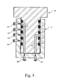
- FIG. 5 is a cross-sectional view of the assembled vale of another embodiment;
- FIG. 6 is a perspective view of a specific rotor and its construction;
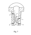
- FIG. 7 is a cross-sectional view of another rotor.
- For exemplary purpose, all Figures for the preferred embodiments have four flow paths for diverting four fluid streams. It should be realized that the valve of the present invention are able to simultaneously divert more fluid streams and the number of flow paths of the valve is not a limit of the present invention.
- FIG. 1 shows one embodiment of the present invention. The embodiment comprises a stator S and a rotor R that is positioned within stator S. Stator S has a
top end 11, abottom end 12, alateral exterior surface 13, acircular cavity 14 with an lateralinterior surface 14 a, and a plurality of external ports extending from lateralexterior surface 13 to the lateralinterior surface 14 a. Said ports are grouped into group A of 4 ports and group B of 4 ports. The ports of group A are designated as port A1 to A4 and are spaced apart longitudinally from saidtop end 11. Ports of group B are designated as ports B1 to B4, are located approximate to thebottom end 12 on a common plan perpendicular to the axis of saidcircular cavity 14, and are equally spaced apart along the circumference of saidcircular cavity 14. Rotor R is of column shape and has atop end 21,bottom end 22, alateral exterior surface 23, and four internal flow passages F1 to F4. Rotor R is positioned incircular cavity 14 rotatable about the axis of the circular cavity. Each of said internal flow passages F has a top opening Cx and a bottom opening Dx on thelateral exterior surface 23 of rotor R wherein x is an integer variable. Openings C are spaced apart longitudinally fromtop end 21 of rotor R in such a way that when rotor R is assembled into stator S each opening C is paired with a corresponding port Ax of stator S on approximate the same plan of the later perpendicular to the axis of saidcircular cavity 14. A plurality ofring structures 24 extend from lateralexterior surface 23 along the rotor circumference on plans perpendicular to the axis ofcircular cavity 14 of statorS. Ring structures 24 locate respectively above the first opening C1, below the last opening C4, and between each neighboring pair of the openings C1 to C4. Ring structures 24 rotatablly seal the interstice between thelateral exterior surface 23 of rotor R and the lateralinterior surface 14 a ofcircular cavity 14 of stator S to form four circular flow channels E1 to E4 that are spaced apart longitudinally. Openings D1 to D4 of rotor R are located on the same plan as ports B of stator S, equally spaced apart along the circumference of rotor R, and aligned with corresponding ports B to form multiple flow paths that extend from ports A, through circular flow channels E, top openings C, internal flow passages F, bottom openings D, to ports B of the stator wherein receivers are connected. A conventional means for leak-proof connection between a stationary member and a rotating member is preferably adapted to the connections between openings D and ports B that includes but not limits to o-rings, graphite discs, and closely contacting surfaces. - To divert four fluid streams with the valve depicted in FIG. 1, rotor R is turned relative to stator S by 90 degrees each time to simultaneously divert four fluid streams from the current receivers to the next receivers. A first fluid entering port A 1 of stator S, correspondingly through circular flow channel E1, top opening C1, internal flow passage F1, bottom opening D1, to port B1 of stator S where receiver 1 is connected. Simultaneously, the remaining three fluid streams flow through corresponding flow paths of said valve to the corresponding receivers. After rotating rotor R by 90 degrees in respect to stator S, port A1 of stator S remains its connection to circular flow channel E1 of rotor R but bottom opening D1 of rotor R is now connected to port B2 of stator S. Said first fluid still enters port A1 of stator S, correspondingly through circular flow channel E1, top opening C1, internal flow passage F1, bottom opening D1, but to port B2 of stator S where receiver 2 is connected. The first fluid is thus diverted from port B1 to port B2. Simultaneously, the rest fluids are diverted to the next corresponding receivers. Said first fluid is diverted back to port B1 again for a new round of fluid diversion after the rotor rotates 4 times to complete a revolution.
- The valve may have more ports B than ports A in some application. However, in order to realize a sequential and cyclic fluid diversion among defined receivers, the number of ports B should be a multiple of the number of ports A. The total number of ports A and ports B and the relative numbers between them is not a limit of the present invention.
-
Ring structures 24 can be formed in different ways. They can be formed by projecting outwardly from thelateral exterior surface 23 of rotor R as shown in FIG. 1. They can also been formed by inward projections from lateralinterior surface 14 of stator S as shown in FIG. 2, or by positioning O-rings between stator S and rotor R as shown in FIG. 3. Unlike the embodiment shown in FIG. 1, thering structures 24 of the embodiment in FIG. 2 are formed by inward projections extending from the lateralinterior surface 14 a of stator S. The assembled valve in FIG. 2 functions the same as the valve described in FIG. 1 and the elements like those previously described are designated by like numerals. - The embodiment in FIG. 3 has
ring structures 24 made of O-rings. These O-rings are preferably secured by grooves along the circumference of the valve. Said grooves can be located on thelateral exterior surface 23 of rotor R as shown in FIG. 3. They can be also located on the lateral interior surface of stator R. The O-rings are preferably made of rubber or plastics for efficient seal between neighboring circular flow channels E. - FIG. 4 shows another modification to the embodiment in FIG. 1.
Circular cavity 14 of stator S has a bottom 15 with abottom exterior surface 15 a and a bottominterior surface 15 b. Said bottom 15 has four Ports B1 to B4 that extend from saidbottom exterior surface 15 a to said bottominterior surface 15 b. Ports B are equally spaced apart along a circular orbit concentric to saidcircular cavity 14. Instead of on thelateral exterior surface 23 of rotor R, four openings D1 to D4 are located on the bottom exterior surface of thebottom end 22 of rotor R and equally spaced apart along a circular orbit that is concentric to rotor R and has the same radius as said circular orbit for ports B of stator S. When rotor R is assembled into the circular cavity of stator S, said bottominterior surface 15 b of stator S is in close contact with the bottom exterior surface of saidbottom end 22 of rotor R to form leak-proof seal, said openings D are aligned with corresponding ports B, and the valve is able to divert fluid streams in a way described for the embodiment in FIG. 1. The rotatable and leak-free connection between a pair of port Bx and port Dx can be realized by any conventional methods mentioned previously. - Though the valves shown in FIG. 1 to FIG. 4 are of truncated conical shape, the valves of the present invention can have other shapes and the geometrical configuration is not the restrict of the present invention. FIG. 5 shows a valve of cylindrical shape modified from the embodiment in FIG. 4. Other configurations, such as conical shape and half-conical/half-cylindrical shape, can also be constructed into the valves of the present invention.
- The internal flow passages F of rotor R are difficult to construct due to the bends and lengths. FIG. 6 and FIG. 7 described two different approaches to form said internal flow passages. In FIG. 6, the rotor R consists of a hollow
tubular structure 300 and a truncatedconical column 400 that is positioned within said hollowtubular structure 300. Hollowtubular structure 300 has a cavity of truncated conical shape and has a plurality of ports C and ports D extending from the lateral exterior surface to the lateral interior surface and positioning at the same location as those described in FIG. 1. A plurality oflongitudinal slots 410 are carved on the lateral exterior surface ofconical column 400 in such a way that each slot connects a port Cx to a corresponding port Dx whencolumn 400 is assembled into hollowtubular structure 300. The tight contact between the lateral interior surface of hollowtubular structure 300 and the lateral exterior surface ofcolumn 400 prevents fluid communications among the slots, forming internal flow passages with an opening Cx at one end and an opening Dx at the opposing end. Saidslots 410 can also be carved on the lateral interior surface of hollow tubular structure with an opening Cx and an opening Dx at the opposing ends of each slot. In this case the lateral exterior surface ofcolumn 400 is preferably smooth for the formation of internal flow passages F. - FIG. 7 shows another approach to construct internal flow passages F. Rotor R has an axially extended cavity and a plurality of openings C and openings D extending from the lateral exterior surface to the lateral interior surface of said cavity. Each opening C x is connected to a corresponding opening Dx with a tube Tx to form a internal flow passage Fx. The leak-proof connection of the tube end to the openings C and D may be realized by any conventional means. It can also be realized by solidifying an appropriate liquid into the cavity. Though the formation of internal flow passages F in FIG. 7 is for the embodiment in FIG. 1, it can apply to the embodiments shown in FIG. 2 and FIG. 3 and other configurations not shown in the Figures but within the scope of the present invention.
- Within the principle of FIG. 6 and FIG. 7 is a modification to the location of openings D in rotor R. Instead of on the lateral exterior, said openings D locate on the bottom end of the rotor for the valves shown in FIG. 4 and FIG. 5. Other constructions are the same as the embodiments shown in FIG. 6 and FIG. 7.
Claims (20)
1. A valve for simultaneously diverting a plurality of liquid streams among a plurality of liquid receivers in a sequential and cyclic manner, said valve comprising:
(1) a stationary stator including opposing top and bottom ends, a lateral exterior surface, a circular cavity with a lateral interior surface, a plurality of external ports extending from the lateral exterior surface to the lateral interior surface, said ports being grouped into group A of n ports and group B of (m*n) ports wherein m and n are integers larger than zero, ports of group A being designated as ports A and being spaced apart longitudinally, ports of group B being designated as ports B, being located approximate to the bottom end on a common plan perpendicular to the axis of said circular cavity, and being equally spaced apart along the circumference of said circular cavity;
(2) a rotor of column shape having opposing top and bottom ends, a lateral exterior surface, and n internal flow passages F, the rotor being located in said circular cavity of the stator and being rotatable about the axis of said circular cavity, each said internal flow passage Fx having a top opening Cx and a bottom opening Dx on the lateral exterior surface of the rotor wherein x is an integer variable, top openings C being longitudinally spaced apart in such a way that each top opening Cx is paired with a corresponding port Ax of the stator on approximate the same plan of corresponding ports A perpendicular to the axis of said circular cavity, bottom openings D being located on the same plan of ports B, equally spaced apart along the circumference of the rotor, and aligned with corresponding ports B, a conventional means for leak-free connection between a rotating member and a stationary member being adapted to the connections between the bottom openings D of the rotor and ports B of the stator that includes but not limits to o-rings, graphite discs, and closely contacting surfaces;
(3) ring structures around the circumference of the rotor being constructed at the interstice of the stator and the rotor between each neighboring pair of top openings C along the rotor circumference on the corresponding plans perpendicular to the axis of said circular cavity, two similar ring structures, one above the first top opening C1 and the other below the last top opening Cn, being similarly constructed, said ring structures rotatablly sealing the interstice between the lateral exterior surface of the rotor and the lateral interior surface of said circular cavity to form n circular flow channels E, multiple flow paths being thus formed in the valve that extend from ports A, through circular flow channels E, top openings C, internal flow passages F, bottom openings D, to ports B of the stator where receivers are connected;
(4) rotating the rotor by 360/(m*n) degrees each time to simultaneously divert multiple fluids from the current receivers to the next receivers, a first fluid entering port A1 of the stator, correspondingly through circular flow channel E1, top opening C1, internal flow passage F1, bottom opening D1, to port B1 of the stator where receiver 1 is connected, simultaneously, the rest fluids flowing through the corresponding flow paths of said valve to the corresponding receivers;
after rotating the rotor by 360/(m*n) degrees in respect to the stator, said first fluid still entering port A1 of the stator, correspondingly through circular flow channel E1, top opening C1, internal flow passage F1, bottom opening D1, but to ports B2 of the stator where receiver 2 is connected, simultaneously, the rest fluids being diverted to the next corresponding receivers, said first fluid being diverted back to port B1 again for a new round of fluid diversion after the rotor rotates (m*n) times to complete a revolution.
2. A valve of claim 1 where the rotor and said circular cavity of the stator is cylindrical.
3. A valve of claim 1 wherein the rotor and said circular cavity of the stator is of truncated conical shape.
4. A valve of claim 1 wherein the rotor and said circular cavity of the stator are of conical shape.
5. A valve of claim 1 wherein said ring structures are formed by projections extending inwardly from the lateral interior surface of said circular cavity of the stator.
6. A valve of claim 1 wherein said ring structures are formed by projections extending outwardly from the lateral exterior surface of the rotor.
7. A valve of claim 1 wherein said ring structures are formed by o-rings, said o-rings being secured by any conventional means including circular grooves in the lateral interior surface of the stator.
8. A valve of claim 1 wherein said ring structures are formed by o-rings, said o-rings being secured by any conventional means including circular grooves in the lateral exterior surface of the rotor.
9. A valve of claim 1 wherein the rotor is constructed by a hollow circular column and a second column, the hollow circular column having a lateral exterior surface, a lateral interior surface, top openings C and bottom openings D extending from the lateral exterior surface to the lateral interior surface, and n slots on the lateral interior surface extending longitudinally from top openings C to corresponding bottom openings D, said second column being tightly inserted into said hollow circular column to enclose said slots to form leak-free internal flow passages F that extend from top openings C through said enclosed slots to corresponding bottom openings D.
10. A valve of claim 1 wherein the rotor is constructed by a hollow circular column and a second column, the hollow circular column having a lateral exterior surface, a lateral interior surface, and top openings C and bottom openings D extending from the lateral exterior surface to the lateral interior surface, said second column having a lateral exterior surface and n slots extending longitudinally on said lateral exterior surface in such a way that each slot connects a top opening Cx at one end and a corresponding bottom opening Dx at the opposing end and forms a leak-free internal flow passage Fx extending from the top opening Cx through a said slot to the corresponding bottom opening Dx when said second column is tightly inserted into said hollow circular column.
11. A valve of claim 1 wherein the rotor is constructed by a hollow circular column with a lateral exterior surface, a lateral interior surface, and n top openings C and n bottom openings D extending from said lateral exterior surface to said lateral interior surface, n tubes being positioned in the hollow circular column with one end connected to said top openings C and the other end connected to corresponding bottom openings D to form internal flow passages F, the tubing connections being optionally secured by adding and solidifying an appropriate liquid in said hollow circular column.
12. A valve of claim 1 wherein said circular cavity of the stator has a bottom with a bottom exterior surface and a bottom interior surface and the bottom end of the rotor has a bottom exterior surface, further modifications to the embodiment of claim A comprising:
(1) instead of on the lateral exterior surface of the stator, ports B being located on the bottom exterior surface of the stator, extending from said bottom exterior surface to said bottom interior surface, and being equally spaced apart along a circular orbit concentric to said circular cavity;
(2) instead of on the lateral exterior surface of the rotor, bottom openings D being located on the bottom exterior surface of said bottom end of the rotor and being equally spaced apart along a circular orbit concentric to said axis of the rotor, said circular orbit having the same radius as the circular orbit along which ports B are spaced apart.
(3) aligning said bottom openings D with corresponding said ports B and forming leak-free contact between a pair of said bottom opening Dx and said port Bx.
13 A valve of claim 12 wherein the rotor is a circular column having a top end, a bottom end, a cavity with an opening at said top end, a lateral exterior surface, a lateral interior surface, a bottom exterior surface, a bottom interior surface, n top openings C extending from said lateral exterior surface to said lateral interior surface, and n bottom openings D extending from said bottom interior surface to said bottom exterior surface, said top openings C being connected to corresponding said bottom openings D by tubes to form internal flow passages F that extend from said top openings C through said tubes to said bottom openings D, the tubing connections being optionally secured by adding and solidifying an appropriate liquid in said hollow circular column.
14. A valve of claim 12 wherein the rotor and said circular cavity of the stator is cylindrical.
15. A valve of claim 12 wherein the rotor and said circular cavity of the stator is of truncated conical shape.
16. A valve of claim 12 wherein the rotor and said circular cavity of the stator are of conical shape.
17. A valve of claim 12 wherein said ring structures are formed by projections extending inwardly from the lateral interior surface of said cavity of the stator.
18. A valve of claim 12 wherein said ring structures are formed by projections extending outwardly from the lateral exterior surface of the rotor.
19. A valve of claim 12 wherein said ring structures are formed by o-rings, said o-rings being secured by any conventional means that includes circular grooves in the lateral interior surface of the stator.
20. A valve of claim 12 wherein said ring structures are formed by o-rings, said o-rings being secured by any conventional means that includes circular grooves in the lateral exterior surface of the rotor.
Priority Applications (1)
| Application Number | Priority Date | Filing Date | Title |
|---|---|---|---|
| US10/411,181 US6904936B2 (en) | 2002-04-19 | 2003-04-10 | Flow-diverting rotary valves of multiple paths |
Applications Claiming Priority (2)
| Application Number | Priority Date | Filing Date | Title |
|---|---|---|---|
| US37423702P | 2002-04-19 | 2002-04-19 | |
| US10/411,181 US6904936B2 (en) | 2002-04-19 | 2003-04-10 | Flow-diverting rotary valves of multiple paths |
Publications (2)
| Publication Number | Publication Date |
|---|---|
| US20030196713A1 true US20030196713A1 (en) | 2003-10-23 |
| US6904936B2 US6904936B2 (en) | 2005-06-14 |
Family
ID=29218973
Family Applications (1)
| Application Number | Title | Priority Date | Filing Date |
|---|---|---|---|
| US10/411,181 Expired - Fee Related US6904936B2 (en) | 2002-04-19 | 2003-04-10 | Flow-diverting rotary valves of multiple paths |
Country Status (1)
| Country | Link |
|---|---|
| US (1) | US6904936B2 (en) |
Cited By (17)
| Publication number | Priority date | Publication date | Assignee | Title |
|---|---|---|---|---|
| WO2005106300A1 (en) * | 2004-04-28 | 2005-11-10 | Hach Company | A single piece, multi-port precision valve |
| WO2007031859A1 (en) * | 2005-09-16 | 2007-03-22 | Tongaat Hulett Limited | Distribution member |
| EP1789708A1 (en) * | 2004-08-25 | 2007-05-30 | Mécanique Analytique Inc. | Rotary valve and analytical chromatographic system using the same |
| KR100806044B1 (en) | 2006-12-29 | 2008-02-26 | 신동만 | Forward/reversible circulating valve device |
| CN100449187C (en) * | 2006-12-14 | 2009-01-07 | 北京科技大学 | Rotary reversing valve used for multichamber thermal accumulating incinerator |
| EP2138748A1 (en) * | 2008-06-26 | 2009-12-30 | Bürkert Werke GmbH & Co. KG | Multiple channel distribution valve |
| US20130112604A1 (en) * | 2010-06-16 | 2013-05-09 | Waters Technologies Corporation | Valve For High Pressure Analytical System |
| US20150204451A1 (en) * | 2012-07-27 | 2015-07-23 | Eveon | Directional control valve for fluid and device for in-situ reconstitution and administering |
| CN106122521A (en) * | 2016-06-28 | 2016-11-16 | 苏州麦可旺志生物技术有限公司 | One kind of multiple fluids periodically directional stream-guidance device |
| CN106246627A (en) * | 2016-08-20 | 2016-12-21 | 黎明液压有限公司 | A kind of rotary control type hydraulicdirectional control valve |
| CN106255849A (en) * | 2014-07-18 | 2016-12-21 | 三菱电机株式会社 | Thermal medium flow passage selector device and the air-conditioning device possessing this thermal medium flow passage selector device |
| CN106574731A (en) * | 2014-08-22 | 2017-04-19 | 三菱电机株式会社 | Compound valve |
| CN106609868A (en) * | 2016-06-28 | 2017-05-03 | 苏州麦可旺志生物技术有限公司 | Periodic oriented flow guide device for various types of fluid |
| US10215452B2 (en) | 2014-07-18 | 2019-02-26 | Mitsubishi Electric Corporation | Air conditioner |
| US11364504B2 (en) * | 2016-06-20 | 2022-06-21 | Integrated Nano-Technologies, Inc. | Multiple rotor disposable cartridge for portable diagnostic assay system |
| US20220364653A1 (en) * | 2019-10-14 | 2022-11-17 | Vitesco Technologies GmbH | Fluid Valve |
| US11566714B2 (en) * | 2020-01-15 | 2023-01-31 | Flowserve Management Company | Fluid flow control devices and related systems and methods |
Families Citing this family (13)
| Publication number | Priority date | Publication date | Assignee | Title |
|---|---|---|---|---|
| US7156322B1 (en) * | 2003-09-22 | 2007-01-02 | Heitzman Charles J | Irrigation sprinkler unit with cycling flow rate |
| US7344686B2 (en) * | 2004-10-07 | 2008-03-18 | Mesoscopic Devices, Inc. | Desulfurization apparatus with individually controllable heaters |
| WO2007112532A1 (en) * | 2006-04-05 | 2007-10-11 | Mitton Valve Technology Inc. | Valve for a fluid flow control system |
| US8033295B2 (en) * | 2007-02-08 | 2011-10-11 | Praxair Technology, Inc. | Multi-output valve useful to promote non-stationary flame |
| WO2008103097A1 (en) * | 2007-02-22 | 2008-08-28 | Ge Healthcare Bio-Sciences Ab | Selection valve |
| US7870870B2 (en) * | 2007-08-20 | 2011-01-18 | Uop Llc | Multiport vertical axial valve with sealing rotor |
| WO2011130071A1 (en) * | 2010-04-13 | 2011-10-20 | Waters Technologies Corporation | Rotary shear injector valve with displaced rotor grooves |
| CN103790877B (en) * | 2012-10-31 | 2016-03-09 | 富泰华工业(深圳)有限公司 | Swivel joint and adopt many gas circuits station of this swivel joint |
| CN107013698B (en) * | 2016-01-26 | 2022-04-12 | 科勒公司 | Valve assembly |
| CN106321897B (en) * | 2016-08-24 | 2018-03-20 | 苏州麦可旺志生物技术有限公司 | One kind of multiple fluid periodicity directional stream-guidance devices |
| US11083980B2 (en) * | 2017-03-03 | 2021-08-10 | Baisheng Zou | Rotary solid/fluid counter-current contacting apparatus |
| US10589190B2 (en) * | 2017-03-03 | 2020-03-17 | Baisheng Zou | Rotary solid/fluid counter-current contact apparatus |
| US11378193B2 (en) * | 2020-06-22 | 2022-07-05 | Northrop Grumman Systems Corporation | Axial diverter/mixing valve |
Citations (7)
| Publication number | Priority date | Publication date | Assignee | Title |
|---|---|---|---|---|
| US2985589A (en) * | 1957-05-22 | 1961-05-23 | Universal Oil Prod Co | Continuous sorption process employing fixed bed of sorbent and moving inlets and outlets |
| US3192954A (en) * | 1963-10-18 | 1965-07-06 | Universal Oil Prod Co | Distributing valve |
| US3706812A (en) * | 1970-12-07 | 1972-12-19 | Universal Oil Prod Co | Fluid-solid contacting apparatus |
| US3814129A (en) * | 1972-09-25 | 1974-06-04 | Squibb & Sons Inc | Sampling valve |
| US4068528A (en) * | 1976-01-19 | 1978-01-17 | Rheodyne Incorporated | Two position rotary valve for injecting sample liquids into an analysis system |
| US4263937A (en) * | 1978-04-21 | 1981-04-28 | Rudenko Nikolai V | Scanning valve |
| US5105851A (en) * | 1990-10-17 | 1992-04-21 | Hewlett-Packard Company | Apparatus for multi-path flow regulation |
-
2003
- 2003-04-10 US US10/411,181 patent/US6904936B2/en not_active Expired - Fee Related
Patent Citations (7)
| Publication number | Priority date | Publication date | Assignee | Title |
|---|---|---|---|---|
| US2985589A (en) * | 1957-05-22 | 1961-05-23 | Universal Oil Prod Co | Continuous sorption process employing fixed bed of sorbent and moving inlets and outlets |
| US3192954A (en) * | 1963-10-18 | 1965-07-06 | Universal Oil Prod Co | Distributing valve |
| US3706812A (en) * | 1970-12-07 | 1972-12-19 | Universal Oil Prod Co | Fluid-solid contacting apparatus |
| US3814129A (en) * | 1972-09-25 | 1974-06-04 | Squibb & Sons Inc | Sampling valve |
| US4068528A (en) * | 1976-01-19 | 1978-01-17 | Rheodyne Incorporated | Two position rotary valve for injecting sample liquids into an analysis system |
| US4263937A (en) * | 1978-04-21 | 1981-04-28 | Rudenko Nikolai V | Scanning valve |
| US5105851A (en) * | 1990-10-17 | 1992-04-21 | Hewlett-Packard Company | Apparatus for multi-path flow regulation |
Cited By (23)
| Publication number | Priority date | Publication date | Assignee | Title |
|---|---|---|---|---|
| WO2005106300A1 (en) * | 2004-04-28 | 2005-11-10 | Hach Company | A single piece, multi-port precision valve |
| EP1789708A1 (en) * | 2004-08-25 | 2007-05-30 | Mécanique Analytique Inc. | Rotary valve and analytical chromatographic system using the same |
| EP1789708A4 (en) * | 2004-08-25 | 2010-03-10 | Mecanique Analytique Inc | Rotary valve and analytical chromatographic system using the same |
| WO2007031859A1 (en) * | 2005-09-16 | 2007-03-22 | Tongaat Hulett Limited | Distribution member |
| CN100449187C (en) * | 2006-12-14 | 2009-01-07 | 北京科技大学 | Rotary reversing valve used for multichamber thermal accumulating incinerator |
| KR100806044B1 (en) | 2006-12-29 | 2008-02-26 | 신동만 | Forward/reversible circulating valve device |
| EP2138748A1 (en) * | 2008-06-26 | 2009-12-30 | Bürkert Werke GmbH & Co. KG | Multiple channel distribution valve |
| DE102008029968A1 (en) * | 2008-06-26 | 2009-12-31 | Bürkert Werke GmbH & Co. KG | Multichannel diverting |
| US20130112604A1 (en) * | 2010-06-16 | 2013-05-09 | Waters Technologies Corporation | Valve For High Pressure Analytical System |
| US9435447B2 (en) * | 2012-07-27 | 2016-09-06 | Eveon | Directional control valve for fluid and device for in-situ reconstitution and administering |
| US20150204451A1 (en) * | 2012-07-27 | 2015-07-23 | Eveon | Directional control valve for fluid and device for in-situ reconstitution and administering |
| EP3171059A4 (en) * | 2014-07-18 | 2018-04-04 | Mitsubishi Electric Corporation | Heating-medium flow-path switching device and air conditioner provided with same |
| CN106255849A (en) * | 2014-07-18 | 2016-12-21 | 三菱电机株式会社 | Thermal medium flow passage selector device and the air-conditioning device possessing this thermal medium flow passage selector device |
| US10215452B2 (en) | 2014-07-18 | 2019-02-26 | Mitsubishi Electric Corporation | Air conditioner |
| US10337626B2 (en) | 2014-07-18 | 2019-07-02 | Mitsubishi Electric Corporation | Heating medium channel switching device, and air conditioning device including the heating medium channel switching device |
| CN106574731A (en) * | 2014-08-22 | 2017-04-19 | 三菱电机株式会社 | Compound valve |
| US10330208B2 (en) | 2014-08-22 | 2019-06-25 | Mitsubishi Electric Corporation | Compound valve |
| US11364504B2 (en) * | 2016-06-20 | 2022-06-21 | Integrated Nano-Technologies, Inc. | Multiple rotor disposable cartridge for portable diagnostic assay system |
| CN106609868A (en) * | 2016-06-28 | 2017-05-03 | 苏州麦可旺志生物技术有限公司 | Periodic oriented flow guide device for various types of fluid |
| CN106122521A (en) * | 2016-06-28 | 2016-11-16 | 苏州麦可旺志生物技术有限公司 | One kind of multiple fluids periodically directional stream-guidance device |
| CN106246627A (en) * | 2016-08-20 | 2016-12-21 | 黎明液压有限公司 | A kind of rotary control type hydraulicdirectional control valve |
| US20220364653A1 (en) * | 2019-10-14 | 2022-11-17 | Vitesco Technologies GmbH | Fluid Valve |
| US11566714B2 (en) * | 2020-01-15 | 2023-01-31 | Flowserve Management Company | Fluid flow control devices and related systems and methods |
Also Published As
| Publication number | Publication date |
|---|---|
| US6904936B2 (en) | 2005-06-14 |
Similar Documents
| Publication | Publication Date | Title |
|---|---|---|
| US6904936B2 (en) | Flow-diverting rotary valves of multiple paths | |
| US8656955B2 (en) | Rotary column selector valve | |
| US9739383B2 (en) | Multi-path selector valve | |
| US6672336B2 (en) | Dual random access, three-way rotary valve apparatus | |
| US10113995B2 (en) | Multi-position, micro-fluidic valve assembly with multiple radial grooves to enable individual or combined flows | |
| EP2113080B1 (en) | Rotary selection valve | |
| CN100356097C (en) | Fluid-directing multiport rotary valve | |
| US10309938B2 (en) | Rotary valve | |
| CA2577824A1 (en) | Rotary valve and analytical chromatographic system using the same | |
| JP6758660B2 (en) | Rotary valve and chromatography system | |
| CN109541094A (en) | A kind of selector valve and liquid-chromatography apparatus | |
| US11717770B2 (en) | Variable fluidic restrictor having selective restriction | |
| JPS6256858A (en) | Flaw passage changing device | |
| CN216843244U (en) | Rotary valve and chromatographic experiment system with same | |
| CN111157662A (en) | Multi-column rotary valve and chromatograph | |
| CN216870473U (en) | Chromatography experiment system and rotary valve | |
| CN107820551B (en) | Improvements in and relating to fluid path networks | |
| US11592116B2 (en) | Five port valve | |
| CN114113430A (en) | Chromatography experiment system and rotary valve | |
| JPS61134668A (en) | Liquid injecting device | |
| CN216843246U (en) | Rotary valve and chromatography experiment system with same | |
| JPS5811012B2 (en) | Fluid quantitative fractionation device | |
| JPS5855806B2 (en) | Desired ratio mixing device for fluids | |
| JPS6161052A (en) | Liquid injector | |
| KR880000722A (en) | Axial Multiport Rotary Valve |
Legal Events
| Date | Code | Title | Description |
|---|---|---|---|
| AS | Assignment |
Owner name: ARCHIDEX, CALIFORNIA Free format text: ASSIGNMENT OF ASSIGNORS INTEREST;ASSIGNOR:MA, QI-FENG;REEL/FRAME:013959/0971 Effective date: 20030410 |
|
| REMI | Maintenance fee reminder mailed | ||
| LAPS | Lapse for failure to pay maintenance fees | ||
| STCH | Information on status: patent discontinuation |
Free format text: PATENT EXPIRED DUE TO NONPAYMENT OF MAINTENANCE FEES UNDER 37 CFR 1.362 |
|
| FP | Lapsed due to failure to pay maintenance fee |
Effective date: 20090614 |