US20030196773A1 - Method for controlling dust on paper machinery and the like - Google Patents
Method for controlling dust on paper machinery and the like Download PDFInfo
- Publication number
- US20030196773A1 US20030196773A1 US10/412,488 US41248803A US2003196773A1 US 20030196773 A1 US20030196773 A1 US 20030196773A1 US 41248803 A US41248803 A US 41248803A US 2003196773 A1 US2003196773 A1 US 2003196773A1
- Authority
- US
- United States
- Prior art keywords
- air
- foil
- exhaust
- baffle
- dust
- Prior art date
- Legal status (The legal status is an assumption and is not a legal conclusion. Google has not performed a legal analysis and makes no representation as to the accuracy of the status listed.)
- Abandoned
Links
Images


Classifications
-
- B—PERFORMING OPERATIONS; TRANSPORTING
- B08—CLEANING
- B08B—CLEANING IN GENERAL; PREVENTION OF FOULING IN GENERAL
- B08B5/00—Cleaning by methods involving the use of air flow or gas flow
-
- B—PERFORMING OPERATIONS; TRANSPORTING
- B08—CLEANING
- B08B—CLEANING IN GENERAL; PREVENTION OF FOULING IN GENERAL
- B08B9/00—Cleaning hollow articles by methods or apparatus specially adapted thereto
-
- D—TEXTILES; PAPER
- D21—PAPER-MAKING; PRODUCTION OF CELLULOSE
- D21G—CALENDERS; ACCESSORIES FOR PAPER-MAKING MACHINES
- D21G3/00—Doctors
-
- D—TEXTILES; PAPER
- D21—PAPER-MAKING; PRODUCTION OF CELLULOSE
- D21G—CALENDERS; ACCESSORIES FOR PAPER-MAKING MACHINES
- D21G3/00—Doctors
- D21G3/005—Doctor knifes
-
- D—TEXTILES; PAPER
- D21—PAPER-MAKING; PRODUCTION OF CELLULOSE
- D21G—CALENDERS; ACCESSORIES FOR PAPER-MAKING MACHINES
- D21G9/00—Other accessories for paper-making machines
-
- B—PERFORMING OPERATIONS; TRANSPORTING
- B65—CONVEYING; PACKING; STORING; HANDLING THIN OR FILAMENTARY MATERIAL
- B65H—HANDLING THIN OR FILAMENTARY MATERIAL, e.g. SHEETS, WEBS, CABLES
- B65H2301/00—Handling processes for sheets or webs
- B65H2301/40—Type of handling process
- B65H2301/41—Winding, unwinding
- B65H2301/414—Winding
- B65H2301/4141—Preparing winding process
- B65H2301/41414—Preparing winding process involving pulper or doctor blade or air knife
-
- B—PERFORMING OPERATIONS; TRANSPORTING
- B65—CONVEYING; PACKING; STORING; HANDLING THIN OR FILAMENTARY MATERIAL
- B65H—HANDLING THIN OR FILAMENTARY MATERIAL, e.g. SHEETS, WEBS, CABLES
- B65H2301/00—Handling processes for sheets or webs
- B65H2301/40—Type of handling process
- B65H2301/41—Winding, unwinding
- B65H2301/417—Handling or changing web rolls
- B65H2301/418—Changing web roll
- B65H2301/4181—Core or mandrel supply
- B65H2301/41816—Core or mandrel supply by core magazine within winding machine, i.e. horizontal or inclined ramp holding cores
-
- B—PERFORMING OPERATIONS; TRANSPORTING
- B65—CONVEYING; PACKING; STORING; HANDLING THIN OR FILAMENTARY MATERIAL
- B65H—HANDLING THIN OR FILAMENTARY MATERIAL, e.g. SHEETS, WEBS, CABLES
- B65H2408/00—Specific machines
- B65H2408/20—Specific machines for handling web(s)
- B65H2408/23—Winding machines
- B65H2408/236—Pope-winders with first winding on an arc of circle and secondary winding along rails
-
- B—PERFORMING OPERATIONS; TRANSPORTING
- B65—CONVEYING; PACKING; STORING; HANDLING THIN OR FILAMENTARY MATERIAL
- B65H—HANDLING THIN OR FILAMENTARY MATERIAL, e.g. SHEETS, WEBS, CABLES
- B65H2801/00—Application field
- B65H2801/84—Paper-making machines
Definitions
- the present invention relates to controlling dust and other contaminants on paper machinery or similar apparatus.
- a necessary step in presently known paper making, tissue making and similar machinery is the drying of the moist paper web on a drum, known as a “Yankee dryer.”
- the heated Yankee dryer rotates constantly, with wet paper web being taken up at one spot on the rotation, and being dried before being scraped off the dryer at another spot in the rotation.
- the web After being scraped off the dryer, the web usually passes through a sensor, measuring the moisture and thickness of the web, and then is taken up by a reel drum.
- the paper web is scraped off the Yankee dryer by a blade known as a “creping doctor.” Usually following the creping doctor is a “cleaning doctor,” which removes any stray material that was left after the paper web is scraped off the dryer. Finally, the dryer is sprayed with a coating prior to taking up a new section of paper web.
- the dust is not the only undesirable byproduct of the operation. Excess moisture, released from the drying, the cleaning and coating solutions or other sources can also adversely affect the operation.
- boundary layer dust has not been adequately captured or eliminated from the system.
- the prior art adequately controlled dust that originally was carried by a boundary layer and subsequently sloughs off the boundary layer as the web travels towards the reel drum.
- the present invention comprises methods and apparatus for controlling dust.
- a foil, an air ramp, a baffle, and exhaust hood are provided to the underside of the web after it is creped off the Yankee dryer.
- the foil separates the boundary layer air containing dust and moisture and, at the same time, provides web stability.
- the foil directs the air to an air ramp, which in turn directs the air along the baffle into an exhaust hood.
- a cleaning jet prevents the dust from sticking to the interior surface of the exhaust hood and an external exhaust system may then remove the moist dust from the exhaust hood.
- the foil is comprised of porous metal, and is internally pressurized. That pressurization provides air flow through the porous metal and creates an “air lubricant” for the web.
- FIG. 1 shows a view of a preferred embodiment installed on a paper making machine.
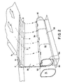
- FIG. 2 shows a front view of the embodiment of FIG. 1.
- FIG. 2 a shows a view of an alternative embodiment.
- FIG. 3 shows a side view of another embodiment of the invention.
- FIG. 1 shows a view of a preferred embodiment installed on a typical paper machine.
- Paper machine and “paper machinery” are used throughout to designate paper machinery and other similar machinery such as tissue making machinery.
- the Yankee dryer of the paper machine is shown at 2 .
- a creping doctor 3 crepes the tissue web or sheet off the dryer. (“Web” and “sheet” are used interchangeably throughout.)
- a cleaning doctor 4 as well as sprays 5 used for applying cleaning and coating solutions.
- the sheet with its attendant boundary layer dust and moisture, shown generally at a, passes by a number of stations, such as upper foils 7 a , 7 b and 7 c , foil 10 , sensor 8 , and various other stations on the way to a reel drum shown generally at 9 .
- the air carried along with the sheet, as well as any unbalanced exhaust present above or below the sheet may cause edge curl and other instability.
- the foils help in minimizing this instability.
- Near foil 10 is a directional air jet 15 , a baffle 20 , a hood surface cleaning air nozzle 30 , a lower sensor hood 35 , and a support 40 .
- the web passes below upper foil 7 c and above foil 10 ; its direction of travel is shown by the arrows.
- Foil 10 directs the boundary layer laden with dust away from the sheet. (“Dust” is used throughout as including dust and other contaminants.)
- the foil 10 is made of solid metal.
- the foil is made of porous metal.
- the porous metal foil which is usually stainless steel, has pore sizes on any particular embodiment ranging from 1 to 100 microns.
- Mounted at the edge of foil 10 is an air jet 11 . Air jet 11 introduces air flow into the porous metal foil. This air flow creates a high pressure region within foil 10 which causes air flow out of the pores of the porous metal foil. This air flow through the porous metal foil generates an “air lubricant,” which reduces friction when the sheet passes over the foil. The reduction in friction and associated drag permits higher sheet speeds through the machinery.
- porous metal foil helps the sheet to travel at higher speeds, the machinery can operate faster, and make more paper or other product faster than would otherwise be the case.
- the porous metal foil can help in increasing production speed.
- the desired amount of lubricant will depend upon the porosity of the foil and the weight of the sheet and so air jet 11 is, in this embodiment, adjustable.
- the path of the boundary layer air shown generally at b is under foil 10 .
- the boundary layer air then mixes with the air ramp air 15 , is directed through the baffle 20 , and into the slot 36 on the exhaust hood 35 .
- the air, laden with dust and moisture, is then exhausted by way of dust control hood exhaust 32 .
- the exhaust hood 35 has a number of features in this embodiment to assist in cleaning any residual dust and moisture.
- removable end plate 31 as well as access doors 33 may be used to access the inside of exhaust hood 35 and so assist in the cleaning operation if necessary.
- the rounded hood plenum 34 allows smooth flow of cleaning nozzle air along the surface.
- FIGS. 1 and 2 provides for portable operation. This embodiment can be placed anywhere along a sheet in order to permit the greatest usability. If desired more than one embodiment can be installed on a web.
- the foil 10 has a more or less rectangular or flat cross section with rounded corners. This shape helps separate the boundary layer from the tissue sheet.
- foil shapes known in the art, such as an oval or aircraft wing cross section, can be used.
- the foil structure can comprise both a foil and an air ramp. FIG. 2 a shows such a foil shape with the foil 51 and air ramp 52 being separately chambered. The air is directed generally along path c.
- the air coming from the foil structure is directed through the baffle, which in turn directs the air to the exhaust.
- the baffle can comprise a ramp or other directional structure, in various embodiments. In those embodiments, the word “through” is used to designate directing the air along or down the baffle, as appropriate.
- the baffle may be integral with and connected to the foil structure and/or the exhaust structure.
- foils can be placed on top and on the bottom of the sheet in various arrangements.
- the offsetting bottom and top foils of FIGS. 1 and 2 is one such arrangement.
- the foil or foils can be comprised of porous metal with any method known in the art used to increase the internal pressure of the foil(s) and thus emit air from the pores and so provide an air lubricant or lubricants to the sheet.
- FIG. 3 shows a side view of another embodiment of the invention.
- the foil 100 has flexible connection 102 to baffle 110 .
- Flexible connection 102 is through means known in the art, for example, hinges or similar means.
- the flexible connection 102 permits foil 100 to be retractable vertically downward when threading the web through the machinery.
- the boundary layer laden with dust and moisture, travels generally along the path seen at a.
- the baffle is hinged for access and in order to increase visibility if desired. It also may be desired, in some embodiments, to include walls along the sides of the baffle, in order to minimize the leakage of any airflow. These walls may of course be removable and/or flexibly connected to the baffle.
- This embodiment uses jet plenum air ramp 105 with an orifice directed downward to entrain boundary layer laden dust and moisture which cannot get past foil 100 and flexible connector 102 .
- the baffle 110 generally helps to reduce the downward force needed to be applied by jet plenum 105 .
- other means known in the art to assist boundary layer flow may be used in other embodiments.
- a jet plenum air ramp or other means known in the art to assist boundary layer flow can be included within the foil structure.
- a small volume high velocity vortex cleaning jet 120 is used in this embodiment inside exhaust hood 125 to assist cleaning and to keep heavier moist dust from settling on the bottom of the hood.
- Support 130 is provided as well.
- Exhaust hood 125 is shaped to maximize the cleaning action of the vortex jet 120 inside the exhaust hood.
- the shape of exhaust hood 125 also helps prevent the vortex jet from being directed out of the exhaust hood slot.
Abstract
A method and apparatus for controlling dust on paper machinery and the like is shown. A foil, a baffle and an exhaust are used to direct contaminated air away from the machinery and the sheet or web of material running through the machinery. Thus the deleterious effect of the contaminants is minimized and contained.
Description
- The present invention relates to controlling dust and other contaminants on paper machinery or similar apparatus.
- A necessary step in presently known paper making, tissue making and similar machinery is the drying of the moist paper web on a drum, known as a “Yankee dryer.” The heated Yankee dryer rotates constantly, with wet paper web being taken up at one spot on the rotation, and being dried before being scraped off the dryer at another spot in the rotation. After being scraped off the dryer, the web usually passes through a sensor, measuring the moisture and thickness of the web, and then is taken up by a reel drum.
- The paper web is scraped off the Yankee dryer by a blade known as a “creping doctor.” Usually following the creping doctor is a “cleaning doctor,” which removes any stray material that was left after the paper web is scraped off the dryer. Finally, the dryer is sprayed with a coating prior to taking up a new section of paper web.
- The creping and cleaning operations create dust, in the form of fibers, tendrils, tiny scraps of paper, etc. Other locations in the machinery also create dust as a byproduct of the operation. The greatest quantity of dust is usually generated below the paper web sheet because of the action of the creping doctor and the cleaning doctor. Controlling the dust is important. Dust can detrimentally affect workers' health, create a fire hazard, ruin the machinery, and interfere with the sensor's operation.
- The dust is not the only undesirable byproduct of the operation. Excess moisture, released from the drying, the cleaning and coating solutions or other sources can also adversely affect the operation.
- The prior art has attempted to control dust by a variety of methods. The majority of these methods involve attempting to collect dust at or very near the creping doctor. See, e.g., U.S. Pat. No. 4,019,953. However, almost invariably, the means used are ineffective because the prior art devices make no allowance for the moisture generated by the paper making procedure. This moisture will clog the dust control devices used by the prior art and so interfere with the dust take-up. A clogged device cannot remove dust from the machinery. This is especially true for the prior art devices which attempt to control the dust at the creping doctor blade. These devices are impractical and quickly fail because of the moisture in the creping doctor blade area which quickly clogs an exhaust hood or other dust control method. Thus, the prior art has failed to solve the problem of moisture-associated clogging in paper making and similar machinery.
- Moreover, a substantial amount of dust and other contaminants is carried by one or more “boundary layers” along the web, after the web has been creped off the Yankee dryer. A boundary layer is usually from four to six inches thick, and located along the top and bottom of the web, with the bottom boundary layer usually carrying the majority of the dust and contaminants. Heretofore, boundary layer dust has not been adequately captured or eliminated from the system. Nor has the prior art adequately controlled dust that originally was carried by a boundary layer and subsequently sloughs off the boundary layer as the web travels towards the reel drum.
- Accordingly, it is an object of the present invention to control both dust and moisture in paper machinery and the like.
- It is a further object of the present invention to control both dust and moisture simply and efficiently.
- It is a further object of the present invention to control both dust and moisture through apparatus and methods that can be added to already existing machinery.
- It is a further object of the present invention to control boundary layer dust and moisture.
- The present invention comprises methods and apparatus for controlling dust. In the preferred embodiments, a foil, an air ramp, a baffle, and exhaust hood are provided to the underside of the web after it is creped off the Yankee dryer. The foil separates the boundary layer air containing dust and moisture and, at the same time, provides web stability. The foil directs the air to an air ramp, which in turn directs the air along the baffle into an exhaust hood. A cleaning jet prevents the dust from sticking to the interior surface of the exhaust hood and an external exhaust system may then remove the moist dust from the exhaust hood.
- In especially preferred embodiments, the foil is comprised of porous metal, and is internally pressurized. That pressurization provides air flow through the porous metal and creates an “air lubricant” for the web.
- FIG. 1 shows a view of a preferred embodiment installed on a paper making machine.
- FIG. 2 shows a front view of the embodiment of FIG. 1.
- FIG. 2 a shows a view of an alternative embodiment.
- FIG. 3 shows a side view of another embodiment of the invention.
- FIG. 1 shows a view of a preferred embodiment installed on a typical paper machine. “Paper machine” and “paper machinery” are used throughout to designate paper machinery and other similar machinery such as tissue making machinery.
- The Yankee dryer of the paper machine is shown at 2. A creping doctor 3, crepes the tissue web or sheet off the dryer. (“Web” and “sheet” are used interchangeably throughout.) Following the creping doctor 3 is a
cleaning doctor 4 as well assprays 5 used for applying cleaning and coating solutions. The sheet, with its attendant boundary layer dust and moisture, shown generally at a, passes by a number of stations, such asupper foils foil 10, sensor 8, and various other stations on the way to a reel drum shown generally at 9. The air carried along with the sheet, as well as any unbalanced exhaust present above or below the sheet, may cause edge curl and other instability. The foils help in minimizing this instability. - Near
foil 10 is adirectional air jet 15, abaffle 20, a hood surfacecleaning air nozzle 30, alower sensor hood 35, and asupport 40. Turning now to FIG. 2 these components are seen in greater detail. The web passes belowupper foil 7 c and abovefoil 10; its direction of travel is shown by the arrows.Foil 10 directs the boundary layer laden with dust away from the sheet. (“Dust” is used throughout as including dust and other contaminants.) - In certain embodiments, the
foil 10 is made of solid metal. In especially preferred embodiments, the foil is made of porous metal. The porous metal foil, which is usually stainless steel, has pore sizes on any particular embodiment ranging from 1 to 100 microns. Mounted at the edge offoil 10 is an air jet 11. Air jet 11 introduces air flow into the porous metal foil. This air flow creates a high pressure region withinfoil 10 which causes air flow out of the pores of the porous metal foil. This air flow through the porous metal foil generates an “air lubricant,” which reduces friction when the sheet passes over the foil. The reduction in friction and associated drag permits higher sheet speeds through the machinery. Because the porous metal foil helps the sheet to travel at higher speeds, the machinery can operate faster, and make more paper or other product faster than would otherwise be the case. Thus the porous metal foil can help in increasing production speed. The desired amount of lubricant will depend upon the porosity of the foil and the weight of the sheet and so air jet 11 is, in this embodiment, adjustable. - The path of the boundary layer air shown generally at b is under
foil 10. The boundary layer air then mixes with theair ramp air 15, is directed through thebaffle 20, and into theslot 36 on theexhaust hood 35. The air, laden with dust and moisture, is then exhausted by way of dustcontrol hood exhaust 32. Theexhaust hood 35 has a number of features in this embodiment to assist in cleaning any residual dust and moisture. There is a surface cleaningair nozzle 30 of a type known in the art which creates a constant flow throughout the inside surface of theexhaust hood 35. Additionally,removable end plate 31 as well asaccess doors 33 may be used to access the inside ofexhaust hood 35 and so assist in the cleaning operation if necessary. Therounded hood plenum 34 allows smooth flow of cleaning nozzle air along the surface. - It should be noted that the embodiment of FIGS. 1 and 2 provides for portable operation. This embodiment can be placed anywhere along a sheet in order to permit the greatest usability. If desired more than one embodiment can be installed on a web.
- In certain preferred embodiments, the
foil 10 has a more or less rectangular or flat cross section with rounded corners. This shape helps separate the boundary layer from the tissue sheet. However, it should be noted other foil shapes known in the art, such as an oval or aircraft wing cross section, can be used. Moreover in other embodiments the foil structure can comprise both a foil and an air ramp. FIG. 2a shows such a foil shape with thefoil 51 andair ramp 52 being separately chambered. The air is directed generally along path c. - Generally, in various embodiments of the present invention, the air coming from the foil structure is directed through the baffle, which in turn directs the air to the exhaust. The baffle can comprise a ramp or other directional structure, in various embodiments. In those embodiments, the word “through” is used to designate directing the air along or down the baffle, as appropriate. In other embodiments, the baffle may be integral with and connected to the foil structure and/or the exhaust structure.
- It will usually be desired to place any embodiments so as to capture the dust in the boundary layer several feet downstream from the creping doctor where the amount of moisture is sharply reduced. It should be noted that foils can be placed on top and on the bottom of the sheet in various arrangements. The offsetting bottom and top foils of FIGS. 1 and 2 is one such arrangement. In the various embodiments of the present convention, the foil or foils can be comprised of porous metal with any method known in the art used to increase the internal pressure of the foil(s) and thus emit air from the pores and so provide an air lubricant or lubricants to the sheet.
- FIG. 3 shows a side view of another embodiment of the invention. The
foil 100 hasflexible connection 102 to baffle 110.Flexible connection 102 is through means known in the art, for example, hinges or similar means. In this embodiment, as well as in others, theflexible connection 102 permits foil 100 to be retractable vertically downward when threading the web through the machinery. - The boundary layer, laden with dust and moisture, travels generally along the path seen at a. In this embodiment, the baffle is hinged for access and in order to increase visibility if desired. It also may be desired, in some embodiments, to include walls along the sides of the baffle, in order to minimize the leakage of any airflow. These walls may of course be removable and/or flexibly connected to the baffle.
- This embodiment uses jet
plenum air ramp 105 with an orifice directed downward to entrain boundary layer laden dust and moisture which cannot getpast foil 100 andflexible connector 102. Thebaffle 110 generally helps to reduce the downward force needed to be applied byjet plenum 105. Of course, other means known in the art to assist boundary layer flow may be used in other embodiments. Additionally, in other embodiments, a jet plenum air ramp or other means known in the art to assist boundary layer flow can be included within the foil structure. - A small volume high velocity
vortex cleaning jet 120 is used in this embodiment insideexhaust hood 125 to assist cleaning and to keep heavier moist dust from settling on the bottom of the hood.Support 130 is provided as well. -
Exhaust hood 125 is shaped to maximize the cleaning action of thevortex jet 120 inside the exhaust hood. The shape ofexhaust hood 125 also helps prevent the vortex jet from being directed out of the exhaust hood slot. - The above description and the views and material depicted by the figures are for purposes of illustration only and are not intended to be, and should not be construed as, limitations on the invention.
- Moreover, certain modifications or alternatives may suggest themselves to those skilled in the art upon reading of this specification, all of which are intended to be within the spirit and scope of the present invention as defined in the attached claims.
Claims (19)
1. A method for controlling contamination in paper making machinery with a sheet traveling throughout the machinery, and air traveling attendant to the sheet, comprising the steps of first, directing said air about a foil means to a baffle means, second, directing said air through said baffle means to an exhaust means, and third, exhausting said air through said exhaust means.
2. The method of claim 1 further comprising the step of air lubricating said sheet as said sheet passes over said foil means.
3. The method of claim 2 further comprising the step of air lubricating said sheet by way of a porous foil means.
4. The method of claim 3 further comprising the step of applying pressure to the inside of said porous foil means.
5. The method of claim 1 further comprising the step of exhausting said air by way of an exhaust hood means.
6. The method of claim 5 further comprising the step of cleaning said exhaust hood means by way of a vortex jet means.
7. An apparatus for controlling dust and other contaminants in paper machinery comprising:
foil means;
baffle means; and,
exhaust means;
whereby, air containing dust and other contaminants attendant to the paper making process, is directed by the foil means to the baffle means and thereby directed to the exhaust means.
8. An apparatus as in claim 7 whereby the foil means is flexibly connected to said baffle means.
9. An apparatus as in claim 7 whereby the foil means is comprised of porous metal.
10. An apparatus as in claim 7 whereby the foil means further comprises a first foil means and an air ramp means.
11. An apparatus as in claim 10 whereby the air ramp means further comprises a jet plenum air ramp.
12. An apparatus as in claim 10 whereby the first foil means is comprised of porous metal.
13. An apparatus as in claim 7 whereby the baffle means is hinged.
14. An apparatus as in claim 7 whereby the exhaust means is further comprised of an exhaust hood means.
15. An apparatus as in claim 14 whereby the exhaust means is further comprised of an exhaust hood means and a cleaning means.
16. An apparatus as in claim 15 whereby said cleaning means is further comprised of a jet cleaning means.
17. An apparatus as in claim 16 whereby said jet cleaning means is further comprised of a vortex jet cleaning means.
18. An apparatus as in claim 15 whereby said cleaning means is further comprised of a removable hood for said exhaust hood means.
19. An apparatus for controlling dust and other contaminants in paper machinery comprising:
foil means comprised of porous metal;
air ramp means;
baffle means; and,
an exhaust hood means;
whereby, air containing dust and other contaminants attendant to the paper making process, is directed by the foil means to the air ramp means, which in turn directs the air to the baffle means and thereby to the exhaust hood means.
Priority Applications (1)
| Application Number | Priority Date | Filing Date | Title |
|---|---|---|---|
| US10/412,488 US20030196773A1 (en) | 2000-08-05 | 2003-04-11 | Method for controlling dust on paper machinery and the like |
Applications Claiming Priority (2)
| Application Number | Priority Date | Filing Date | Title |
|---|---|---|---|
| US09/634,602 US6565711B1 (en) | 2000-08-05 | 2000-08-05 | Method for controlling dust on paper machinery and the like |
| US10/412,488 US20030196773A1 (en) | 2000-08-05 | 2003-04-11 | Method for controlling dust on paper machinery and the like |
Related Parent Applications (1)
| Application Number | Title | Priority Date | Filing Date |
|---|---|---|---|
| US09/634,602 Division US6565711B1 (en) | 2000-08-05 | 2000-08-05 | Method for controlling dust on paper machinery and the like |
Publications (1)
| Publication Number | Publication Date |
|---|---|
| US20030196773A1 true US20030196773A1 (en) | 2003-10-23 |
Family
ID=24544473
Family Applications (2)
| Application Number | Title | Priority Date | Filing Date |
|---|---|---|---|
| US09/634,602 Expired - Fee Related US6565711B1 (en) | 2000-08-05 | 2000-08-05 | Method for controlling dust on paper machinery and the like |
| US10/412,488 Abandoned US20030196773A1 (en) | 2000-08-05 | 2003-04-11 | Method for controlling dust on paper machinery and the like |
Family Applications Before (1)
| Application Number | Title | Priority Date | Filing Date |
|---|---|---|---|
| US09/634,602 Expired - Fee Related US6565711B1 (en) | 2000-08-05 | 2000-08-05 | Method for controlling dust on paper machinery and the like |
Country Status (1)
| Country | Link |
|---|---|
| US (2) | US6565711B1 (en) |
Cited By (2)
| Publication number | Priority date | Publication date | Assignee | Title |
|---|---|---|---|---|
| JP2018103153A (en) * | 2016-12-28 | 2018-07-05 | ヒューグル開発株式会社 | Foreign matter removal apparatus and foreign matter removal method |
| US11318509B2 (en) * | 2017-11-06 | 2022-05-03 | Air Systems Design, Inc. | Dust hood |
Families Citing this family (9)
| Publication number | Priority date | Publication date | Assignee | Title |
|---|---|---|---|---|
| DE60212194T2 (en) * | 2002-01-30 | 2007-06-06 | Vijai Electricals Ltd., Hyderabad | MACHINE FOR THE CONTINUOUS WINDING OF THIN METAL BANDS ON COILS |
| DE10339262A1 (en) * | 2003-08-26 | 2005-03-17 | Voith Paper Patent Gmbh | Web guiding means |
| ITFI20050131A1 (en) * | 2005-06-10 | 2006-12-11 | Milltech S R L | CLEANING DEVICE, IN PARTICULAR FOR PAPER PRODUCTION PLANTS |
| ITFI20050161A1 (en) * | 2005-07-22 | 2007-01-23 | Milltech S R L | STABILIZATION DEVICE FOR FORMING PAPER RIBBONS |
| US7718037B2 (en) * | 2007-04-26 | 2010-05-18 | The Procter & Gamble Company | Creping foil for redirecting dust |
| IT1406647B1 (en) * | 2010-09-16 | 2014-03-07 | Milltech S R L | SUCTION CASE GROUP |
| US10023996B1 (en) * | 2015-09-29 | 2018-07-17 | Brunn Air Systems, Inc | Dust control system for through-air drying machine |
| EP3269875B1 (en) * | 2016-07-12 | 2019-03-20 | Valmet S.p.A. | A dust-handling device for collecting and handling dust in a paper-making environment |
| EP3305980B1 (en) * | 2016-10-05 | 2019-01-30 | Valmet S.p.A. | A system and a method for collecting and handling dust in a paper-making environment |
Citations (12)
| Publication number | Priority date | Publication date | Assignee | Title |
|---|---|---|---|---|
| US4628618A (en) * | 1984-03-02 | 1986-12-16 | Valmet Oy | Apparatus in a drying section of a paper machine |
| US4643775A (en) * | 1984-06-29 | 1987-02-17 | Crown Zellerbach Corporation | Fabric conditioning and cleaning system |
| US4906333A (en) * | 1987-10-01 | 1990-03-06 | Valmet Paper Machinery, Inc. | Method and apparatus for extracting dust that is released when creping off a paper web |
| US5466298A (en) * | 1993-10-01 | 1995-11-14 | James River Paper Company, Inc. | Web cleaning method |
| US5635031A (en) * | 1995-07-06 | 1997-06-03 | Valmet Corporation | Method in a paper machine or in a finishing device of a paper machine for collecting and removing dust separated from a web |
| US5759352A (en) * | 1996-05-24 | 1998-06-02 | Lau; Jark C. | Apparatus for stabilizing a moving low-strength sheet |
| US5800679A (en) * | 1996-10-25 | 1998-09-01 | Valmet Corporation | Device in a paper machine or in a finishing device of a paper machine for removing dust |
| US5967457A (en) * | 1996-07-23 | 1999-10-19 | Thermo Wisconsin, Inc. | Airfoil web stabilization and turning apparatus and method |
| US5970627A (en) * | 1997-12-11 | 1999-10-26 | Thermo Wisconsin, Inc. | Active web stabilization apparatus |
| US6068735A (en) * | 1997-02-03 | 2000-05-30 | Fort James France | Dust-controlling apparatus, with a water curtain device, for a paper manufacturing machine |
| US6193846B1 (en) * | 1998-02-09 | 2001-02-27 | Valmet Corporation | Method and a system in a paper web finishing machine of equivalent |
| US6328852B1 (en) * | 1999-08-24 | 2001-12-11 | Kimberly-Clark Worldwide, Inc. | Method and apparatus for improving stability of moving webs |
Family Cites Families (5)
| Publication number | Priority date | Publication date | Assignee | Title |
|---|---|---|---|---|
| GB1599900A (en) * | 1977-11-30 | 1981-10-07 | Rawicki B J | Dust extraction apparatus |
| US6148831A (en) * | 1996-10-25 | 2000-11-21 | Valmet Corporation | Method for cleaning a web |
| FI111475B (en) * | 1997-09-24 | 2003-07-31 | Metso Paper Inc | Method and arrangement for controlling fog and dust in paper and board manufacturing and finishing |
| US6033303A (en) * | 1998-06-08 | 2000-03-07 | Valmet, Inc. | Tertiary dust control process and system for use in the machine room of a papermaking plant |
| US6176898B1 (en) * | 1999-04-09 | 2001-01-23 | Valmet, Inc. | Method and system for collecting and handling dust in a papermachine environment |
-
2000
- 2000-08-05 US US09/634,602 patent/US6565711B1/en not_active Expired - Fee Related
-
2003
- 2003-04-11 US US10/412,488 patent/US20030196773A1/en not_active Abandoned
Patent Citations (15)
| Publication number | Priority date | Publication date | Assignee | Title |
|---|---|---|---|---|
| US4628618A (en) * | 1984-03-02 | 1986-12-16 | Valmet Oy | Apparatus in a drying section of a paper machine |
| US4643775A (en) * | 1984-06-29 | 1987-02-17 | Crown Zellerbach Corporation | Fabric conditioning and cleaning system |
| US4906333A (en) * | 1987-10-01 | 1990-03-06 | Valmet Paper Machinery, Inc. | Method and apparatus for extracting dust that is released when creping off a paper web |
| US5466298A (en) * | 1993-10-01 | 1995-11-14 | James River Paper Company, Inc. | Web cleaning method |
| US5577294A (en) * | 1993-10-01 | 1996-11-26 | James River Paper Company, Inc. | Web cleaner apparatus and method |
| US5635031A (en) * | 1995-07-06 | 1997-06-03 | Valmet Corporation | Method in a paper machine or in a finishing device of a paper machine for collecting and removing dust separated from a web |
| US5759352A (en) * | 1996-05-24 | 1998-06-02 | Lau; Jark C. | Apparatus for stabilizing a moving low-strength sheet |
| US5888349A (en) * | 1996-05-24 | 1999-03-30 | Kimberly-Clark Worldwide, Inc. | Method for stabilizing a moving low-strength sheet |
| US6039842A (en) * | 1996-05-24 | 2000-03-21 | Lau; Jark C. | Method and apparatus for stabilizing a moving low-strength sheet |
| US5967457A (en) * | 1996-07-23 | 1999-10-19 | Thermo Wisconsin, Inc. | Airfoil web stabilization and turning apparatus and method |
| US5800679A (en) * | 1996-10-25 | 1998-09-01 | Valmet Corporation | Device in a paper machine or in a finishing device of a paper machine for removing dust |
| US6068735A (en) * | 1997-02-03 | 2000-05-30 | Fort James France | Dust-controlling apparatus, with a water curtain device, for a paper manufacturing machine |
| US5970627A (en) * | 1997-12-11 | 1999-10-26 | Thermo Wisconsin, Inc. | Active web stabilization apparatus |
| US6193846B1 (en) * | 1998-02-09 | 2001-02-27 | Valmet Corporation | Method and a system in a paper web finishing machine of equivalent |
| US6328852B1 (en) * | 1999-08-24 | 2001-12-11 | Kimberly-Clark Worldwide, Inc. | Method and apparatus for improving stability of moving webs |
Cited By (4)
| Publication number | Priority date | Publication date | Assignee | Title |
|---|---|---|---|---|
| JP2018103153A (en) * | 2016-12-28 | 2018-07-05 | ヒューグル開発株式会社 | Foreign matter removal apparatus and foreign matter removal method |
| WO2018123715A1 (en) * | 2016-12-28 | 2018-07-05 | ヒューグル開発株式会社 | Foreign-matter removing device and foreign-matter removing method |
| TWI668056B (en) * | 2016-12-28 | 2019-08-11 | 日商修谷魯開發股份有限公司 | Foreign matter removing device and foreign matter removing method |
| US11318509B2 (en) * | 2017-11-06 | 2022-05-03 | Air Systems Design, Inc. | Dust hood |
Also Published As
| Publication number | Publication date |
|---|---|
| US6565711B1 (en) | 2003-05-20 |
Similar Documents
| Publication | Publication Date | Title |
|---|---|---|
| US6565711B1 (en) | Method for controlling dust on paper machinery and the like | |
| US6743478B1 (en) | Curtain coater and method for curtain coating | |
| JP3094216B2 (en) | Web support foil | |
| FI82105C (en) | SAETTING THE ORGANIZATION FOR THE PORTFOLIO AV DAMM SOM FRIGOERS VID LOSSKRAEPPNING AV EN PAPPERSBANA. | |
| EP1142647B1 (en) | Coating apparatus and coating method | |
| US20040074440A1 (en) | Assembly for treating a web of paper or paperboard | |
| JPH0616879B2 (en) | Coating device and method | |
| EP1584377A2 (en) | Coating apparatus | |
| US5759352A (en) | Apparatus for stabilizing a moving low-strength sheet | |
| US6177137B1 (en) | Method in film transfer coating and equipment intended for carrying out the method | |
| JPH07323208A (en) | Method and device for collecting and removing dust seperatedfrom web in paper making machine or finishing device thereof | |
| US6457204B1 (en) | Device for dust removal from a moving paper web | |
| WO1997011814A1 (en) | A method and apparatus for cutting the edge of a moving paper web | |
| FI81400B (en) | FOERFARANDE OCH ANORDNING I EN PAPPERSMASKIN I KILUTRYMMET MELLAN INLOPPSLAODANS LAEPPBALK OCH BROESTVALSEN. | |
| US7326301B2 (en) | Application device | |
| CA2152645A1 (en) | Spray-coating method and spray coater | |
| JPH0378146B2 (en) | ||
| US5848452A (en) | Roll cleaning apparatus | |
| JP5239011B2 (en) | Air cut device for tandem curtain coater | |
| US3550553A (en) | Air knife coating pan | |
| JP4001351B2 (en) | Dust removal equipment | |
| JP3328721B2 (en) | Lip coater type coating equipment | |
| JP3251907B2 (en) | Vacuum coating equipment | |
| JPS62183874A (en) | Coating control apparatus | |
| JPS6127114B2 (en) |
Legal Events
| Date | Code | Title | Description |
|---|---|---|---|
| STCB | Information on status: application discontinuation |
Free format text: ABANDONED -- FAILURE TO RESPOND TO AN OFFICE ACTION |