US20030196926A1 - Multi-functional base for a plastic, wide-mouth, blow-molded container - Google Patents
Multi-functional base for a plastic, wide-mouth, blow-molded container Download PDFInfo
- Publication number
- US20030196926A1 US20030196926A1 US10/444,616 US44461603A US2003196926A1 US 20030196926 A1 US20030196926 A1 US 20030196926A1 US 44461603 A US44461603 A US 44461603A US 2003196926 A1 US2003196926 A1 US 2003196926A1
- Authority
- US
- United States
- Prior art keywords
- annular wall
- container
- base
- container according
- periphery
- Prior art date
- Legal status (The legal status is an assumption and is not a legal conclusion. Google has not performed a legal analysis and makes no representation as to the accuracy of the status listed.)
- Abandoned
Links
Images


Classifications
-
- B—PERFORMING OPERATIONS; TRANSPORTING
- B65—CONVEYING; PACKING; STORING; HANDLING THIN OR FILAMENTARY MATERIAL
- B65D—CONTAINERS FOR STORAGE OR TRANSPORT OF ARTICLES OR MATERIALS, e.g. BAGS, BARRELS, BOTTLES, BOXES, CANS, CARTONS, CRATES, DRUMS, JARS, TANKS, HOPPERS, FORWARDING CONTAINERS; ACCESSORIES, CLOSURES, OR FITTINGS THEREFOR; PACKAGING ELEMENTS; PACKAGES
- B65D1/00—Containers having bodies formed in one piece, e.g. by casting metallic material, by moulding plastics, by blowing vitreous material, by throwing ceramic material, by moulding pulped fibrous material, by deep-drawing operations performed on sheet material
- B65D1/02—Bottles or similar containers with necks or like restricted apertures, designed for pouring contents
- B65D1/0223—Bottles or similar containers with necks or like restricted apertures, designed for pouring contents characterised by shape
- B65D1/0261—Bottom construction
- B65D1/0284—Bottom construction having a discontinuous contact surface, e.g. discrete feet
-
- B—PERFORMING OPERATIONS; TRANSPORTING
- B65—CONVEYING; PACKING; STORING; HANDLING THIN OR FILAMENTARY MATERIAL
- B65D—CONTAINERS FOR STORAGE OR TRANSPORT OF ARTICLES OR MATERIALS, e.g. BAGS, BARRELS, BOTTLES, BOXES, CANS, CARTONS, CRATES, DRUMS, JARS, TANKS, HOPPERS, FORWARDING CONTAINERS; ACCESSORIES, CLOSURES, OR FITTINGS THEREFOR; PACKAGING ELEMENTS; PACKAGES
- B65D21/00—Nestable, stackable or joinable containers; Containers of variable capacity
- B65D21/02—Containers specially shaped, or provided with fittings or attachments, to facilitate nesting, stacking, or joining together
- B65D21/0209—Containers specially shaped, or provided with fittings or attachments, to facilitate nesting, stacking, or joining together stackable or joined together one-upon-the-other in the upright or upside-down position
- B65D21/023—Closed containers provided with local cooperating elements in the top and bottom surfaces, e.g. projection and recess
- B65D21/0231—Bottles, canisters or jars whereby the neck or handle project into a cooperating cavity in the bottom
-
- B—PERFORMING OPERATIONS; TRANSPORTING
- B65—CONVEYING; PACKING; STORING; HANDLING THIN OR FILAMENTARY MATERIAL
- B65D—CONTAINERS FOR STORAGE OR TRANSPORT OF ARTICLES OR MATERIALS, e.g. BAGS, BARRELS, BOTTLES, BOXES, CANS, CARTONS, CRATES, DRUMS, JARS, TANKS, HOPPERS, FORWARDING CONTAINERS; ACCESSORIES, CLOSURES, OR FITTINGS THEREFOR; PACKAGING ELEMENTS; PACKAGES
- B65D79/00—Kinds or details of packages, not otherwise provided for
- B65D79/005—Packages having deformable parts for indicating or neutralizing internal pressure-variations by other means than venting
- B65D79/008—Packages having deformable parts for indicating or neutralizing internal pressure-variations by other means than venting the deformable part being located in a rigid or semi-rigid container, e.g. in bottles or jars
- B65D79/0081—Packages having deformable parts for indicating or neutralizing internal pressure-variations by other means than venting the deformable part being located in a rigid or semi-rigid container, e.g. in bottles or jars in the bottom part thereof
Definitions
- the present invention relates to a base for a wide mouth blow-molded plastic container, and more particularly, the present invention relates to a multi-functional base structure which enables use of the container in hot-fill, as well as pasteurization/retort processing.
- Plastic blow-molded containers particularly those molded of PET, have been utilized in hot fill applications where the container is filled with a liquid product heated to a temperature in excess of 180° F. (82° C.), capped immediately after filling, and allowed to cool to ambient temperatures.
- Plastic blow-molded containers have also been utilized in pasteurization/retort processes where a filled and sealed container is subjected to thermal processing and is then cooled to ambient temperatures. In both cases, the containers are typically provided with vacuum absorption panels to accommodate volumetric changes in the container as the contents of the sealed container are heated and/or as the contents cool within the sealed container.
- U.S. Pat. No. 6,439,413 issued to Prevot et al. and assigned to Graham Packaging Company, L.P. discloses a hot-fillable and retortable plastic wide-mouth blow-molded container having a sidewall with a pair of flex panels.
- Containers having non-paneled sidewalls and yieldable endwall structures are disclosed in U.S. Pat. Nos. 4,642,968, 4,667,454 and 4,880,129 issued to McHenry et al.; 5,217,737 issued to Gygax et al.; 5,234,126 issued to Jonas et al.; 4,381,061 issued to Cerny et al.; 4,125,632 issued to Vosti et al.; and 3,409,167 issued to Blanchard.
- the above cited U.S. patents disclose containers having various base structures.
- U.S. Pat. No. 4,321,483 issued to Dechenne et al. discloses a base having slightly angled annular surface and a central conical projection; and U.S. Pat. No. 4,386,701 issued to Galer discloses a blow molded plastic drum having a base which is designed to stack efficiently with the lid of a like drum.
- the base structure should be capable of accommodating increased internal pressure experienced during pasteurization; capable of accommodating vacuum formed in the sealed container during cool down; capable of resisting unwanted inversion or like deformation; and capable of efficient stacking with like containers.
- a primary object of the present invention is to provide a commercially satisfactory wide-mouth blow-molded container that can be utilized in hot-fill applications as well as pasteurization, or retort, applications for packaging fluent, viscous and solid food products.
- Another object of the present invention is to provide a base structure capable of accommodating an increase in internal container pressure when the sealed container is subjected to thermal treatment and capable of accommodating vacuum during cool down.
- Still another object of the present invention is to provide a hot-fillable and pasteurizable container having a base which accommodates changes in internal pressure and volume and which resists unwanted inversion and other deformation.
- a further object of the present invention is to provide a structure for a wide-mouth plastic container which can be efficiently stacked, one on top of the other, with like containers and which can be produced by means of high speed manufacturing equipment in an economical manner that ensures consistent quality and performance.
- the present invention provides a blow molded plastic container having a base with a continuous or discontinuous concave outer annular wall having an outer portion and an inner portion forming a standing ring therebetween.
- the base also includes an inner annular wall that extends within the outer annular wall and above the standing ring.
- the inner periphery of the inner annular wall is made of blow molded plastic material that is heat-set and biaxially-oriented and connects to an anti-inverting central dimple.
- the inner annular wall is capable of flexing upwardly and downwardly in response to variations in pressures in a filled and sealed container without undergoing unwanted permanent deformation.
- a shoulder extends radially inward on the inner portion of the outer annular wall above a level of the standing ring to facilitate vertical stacking of containers having like bases.
- FIG. 1 is a perspective view of a container having a base embodying the present invention
- FIG. 2 is an elevational view of the container illustrated in FIG. 1;
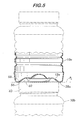
- FIG. 3 is bottom plan view of the base illustrated in FIG. 1;
- FIG. 4 is a cross-sectional view of the base taken along line 4 -- 4 of FIG. 3;
- FIG. 5 is a cross-sectional view of the base taken along line 5 -- 5 of FIG. 2 and illustrates a pair of containers in a stacked arrangement
- FIG. 6 is a perspective view of a second embodiment of a container having a base embodying the present invention.
- FIG. 7 is an elevational view of the container illustrated in FIG. 6;
- FIG. 8 is bottom plan view of the base illustrated in FIG. 6;
- FIG. 9 is a cross-sectional view of the base taken along line 9 -- 9 of FIG. 8;
- FIG. 10 is a cross-sectional view of the base taken along line 10 -- 10 of FIG. 7 and illustrates a pair of containers in a stacked arrangement.
- the present invention provides containers, 10 and 100 , which are particularly suited for use as a jar for packaging food products.
- the containers 10 and 100 can be used to package fluent or semi-fluent food products such as applesauce, spaghetti sauce, relishes, sauerkraut, baby foods, and the like. They can also be used to package a solid food product suspended in a liquid brine, such as pickles.
- the containers, 10 and 100 can be utilized for packaging various food products and can withstand various fill and treatment operations, as will be discussed.
- FIGS. 1 - 5 The embodiment of the present invention illustrated in FIGS. 1 - 5 is a container 10 having a base 12 , a substantially cylindrical sidewall 14 , and a wide-mouth threaded finish 16 which projects from the upper end of the sidewall 14 via a shoulder 18 .
- upper and lower label bumpers, 20 and 22 are located adjacent the shoulder 14 and base 12 , respectfully, and outline a substantially cylindrical label area 24 on the sidewall 14 .
- a label (not shown) can be attached to, and extend completely around, the container sidewall 14 .
- the sidewall 14 has a series of circumferential grooves 26 which reinforce the cylindrical shape of the sidewall 14 and resist paneling, dents and other unwanted deformation of the sidewall 14 .
- the container 10 is multi-functional since it can be utilized in hot-fill as well as pasteurization/retort processing.
- the base 12 has a structure which is capable of accommodating elevated internal container pressure experienced during pasteurization/retort processing and which is capable of accommodating reduced container volume experienced upon cool down of a filled and sealed container after hot-fill or pasteurization/retort processing.
- the base 12 flexes downwardly in a controlled manner and to a desired extent when pressure within the filled and sealed container is elevated, and the base 12 flexes upwardly in a controlled manner and to a desired extent when a vacuum develops within the filled and sealed container.
- the base 12 includes a continuous or discontinuous concave outer annular wall 28 .
- concave outer annular wall 28 is discontinuous and provides a plurality of spaced-apart, arcuate supports 30 adjacent the outer periphery 32 of the base 12 .
- supports 30 are utilized in the illustrated embodiment; however, two, three, five or more supports 30 could also be utilized.
- Yet another alternative includes providing concave outer annular wall 28 as a continuous structure that forms a continuous standing ring.
- Each support 30 has an outer wall portion 34 which extends upwardly toward the lower label bumper 22 and an inner wall portion 36 which extends upwardly and inwardly into the remaining base structure as will be discussed.
- a standing surface 38 is formed at the juncture of each outer and inner wall portions, 34 and 36 .
- a discontinuous support ring of the container 10 is provided in the illustrated embodiment.
- a continuous support ring can be provided.
- An inner annular wall 40 extends within the concave outer annular wall 28 and may, or may not, be slightly inclined relative to the horizontal.
- the inclined inner annular wall 40 can extend upwardly and inwardly at an angle “A” relative to the horizontal as it extends from its outer periphery 42 to its inner periphery 44 .
- the inner annular wall 40 can incline at an angle “A” in a range of about 5° to about 6° relative to a horizontal plane “P” extending through the standing surfaces 38 .
- the inner annular wall 40 can be formed substantially planar and parallel to a horizontal plane “P” extending through the standing surfaces 38 .
- the outer periphery 42 of the inner annular wall 40 merges with the inner wall portion 36 and, in the illustrated embodiment, with a plurality of spaced-apart, horizontally-disposed, radial webs 46 located adjacent the outer periphery 32 of the base 12 .
- Each of the webs 46 extends between the supports 30 and connects to the container sidewall 14 at an elevation above the horizontal plane “P” extending through the standing surfaces 38 .
- a base having a continuous outer annular wall would not include webs 46 .
- the inner periphery 44 of the inner annular wall 40 merges into an anti-inverting dome 48 which projects upwardly into the container 10 .
- the inner annular wall 40 and anti-inverting dome 48 merge via an annular hinge 50 .
- the anti-inverting dome 48 has a conical lower portion 52 adjacent hinge 50 and a convex upper portion 54 .
- the inner annular wall 40 functions as a flex panel. To this end, when the internal pressure increases within a filled and sealed container, the inner annular wall 40 flexes downwardly as shown in dashed lines “B” in FIG. 4 to accommodate the increased pressure and prevent the sidewall 14 of the container 10 from undergoing unwanted permanent distortion. In addition, the inner annular wall 40 flexes upwardly to relieve vacuum when the contents of a hot filled and capped container, or a filled, capped and subsequently pasteurized container, cool to ambient. This is shown in dashed lines “C” in FIG. 4.
- the sidewall 14 when the sealed container and contents cool to ambient, the sidewall 14 is substantially cylindrical and unchanged from its as-formed shape and is capable of neatly supporting a wrap-around label without unwanted voids or the like beneath the label.
- the sidewall 14 resists ovalization and the base 12 provides a level seating surface which is not subject to rocking or the like.
- the anti-inverting dome 48 , the supports 30 and the radial webs 46 support the inner annular wall 40 and permit it to flex only within a desired range of movement as illustrated by dashed lines “B” and “C”. For instance, the inner annular wall 40 flexes downwardly due to an increase in pressure within the container, but is prevented from complete inversion and failure by the anti-inverting dome 48 which travels with the inner annular wall 40 but substantially maintains a constant shape regardless of the internal pressure experienced within the container.
- each inner wall portion 36 of the arcuate supports 30 has an arcuate shoulder, or support ridge, 56 formed therein and spaced in elevation from both the support surfaces 38 and the inner annular wall 40 to facilitate vertical stacking of like containers 10 .
- an upper container 10 a is stacked on a lower container 10 b .
- the support ridge 56 in the base 12 a of the upper container 10 a seats on the outer edge 58 of the upper surface 60 of the lid 62 of the lower container 10 b such that the horizontal plane “Pa” extending through the standing surfaces 38 a of the upper container 10 a extends a spaced distance beneath the top surface 60 of the lid 62 of the lower container 10 b.
- the container 10 preferably has a height “H” of about 5.8 inches, a container outermost diameter “D” of about 4.2 inches, and contain a capacity of about 32 fluid ounces.
- the discontinuous standing ring formed by the standing surfaces 38 has a diameter of about 3.6 inches, and the inner annular wall 40 of the base 12 has an inner periphery 44 with a diameter of about 1.6 inches and an outer periphery 42 with a diameter of about 2.2 inches.
- the radial webs 46 are uniformly spaced apart and separate each support 30 such that each support 30 is at least about 0.8 radians.
- each support 30 has a slightly larger arcuate extent than that of each radial web 46 .
- FIGS. 6 - 10 A second embodiment of the of the present invention is illustrated in FIGS. 6 - 10 as container 100 .
- Container 100 has a base 112 , a sidewall 114 , and a wide-mouth threaded finish 116 which projects from the upper end of the sidewall 114 via a shoulder 118 .
- upper and lower label bumpers, 120 and 122 are located adjacent the shoulder 114 and base 112 , respectfully, and outline a substantially cylindrical label area 124 on the sidewall 114 .
- the sidewall 114 has a series of circumferential grooves 126 which reinforce the sidewall 114 and resist paneling, dents and other unwanted deformation of the sidewall 114 .
- the container 100 is multi-functional since it can be utilized in hot-fill as well as pasteurization/retort processing.
- the base 112 has a structure which is capable of accommodating elevated internal container pressure experienced during pasteurization/retort processing and which is capable of accommodating reduced container volume experienced upon cool down of a filled and sealed container after hot-fill or pasteurization/retort processing.
- the base 112 flexes downwardly in a controlled manner and to a desired extent when pressure within the filled and sealed container is elevated, and the base 112 flexes upwardly in a controlled manner and to a desired extent when a vacuum develops within the filled and sealed container.
- the base 112 includes a concave outer annular wall 128 that is either continuous or discontinuous.
- base 112 has a discontinuous concave outer annular wall 128 that provides a plurality of spaced-apart, arcuate supports 130 adjacent the outer periphery 132 of the base 112 .
- Each support 130 has an outer wall portion 134 that extends upwardly toward the lower label bumper 122 and an inner wall portion 136 that extends upwardly and inwardly into the remaining base structure as will be discussed.
- a standing surface 138 is formed at the juncture of each outer and inner wall portions, 134 and 136 , thereby forming a discontinuous support ring of the container 100 .
- the concave outer annular wall 128 is provided as a continuous structure that forms a continuous support ring.
- An inner annular wall 140 extends within the concave outer annular wall 128 .
- the inner annular wall 140 has an outer periphery 142 and an inner periphery 144 .
- the outer periphery 142 of the inner annular wall 140 merges with the inner wall portion 136 of each of the supports 130 and, in the illustrated embodiment, with a plurality of spaced-apart, horizontally-disposed, radial webs 146 located adjacent the outer periphery 132 of the base 112 .
- Each of the webs 146 extends between the supports 130 and connects to the container sidewall 114 at an elevation above the horizontal plane “P” extending through the standing surface 138 .
- the concave outer annular wall 128 is continuous, webs 146 are not provided.
- the inner periphery 144 of the inner annular wall 140 merges into an anti-inverting central dimple 148 .
- the inner annular wall 140 functions as a flex panel. To this end, when the internal pressure increases within a filled and sealed container, the inner annular wall 140 flexes downwardly to accommodate the increased pressure and to prevent the sidewall 114 of the container 100 from undergoing unwanted permanent distortion. In addition, the inner annular wall 140 flexes upwardly to relieve vacuum when the contents of a hot filled and capped container, or a filled, capped and subsequently pasteurized container, cool to ambient. Thus, when the sealed container and contents cool to ambient, the sidewall 114 is substantially unchanged from its as-formed shape and is capable of neatly supporting a wrap-around label without unwanted voids or the like beneath the label. In addition, the sidewall 114 resists ovalization and the base 112 provides a level seating surface which is not subject to rocking or the like.
- the base 112 of container 100 is specifically designed to provide greater flexural movement than base 12 of container 10 discussed above so that it can be utilized in processes that require relatively high hot-fill and/or pasteurization/retort temperatures.
- Increasing flexure of the base 112 is accomplished by providing a larger circular flat between the dimple 148 and the arcuate supports 130 .
- the inner annular wall 140 of container 100 is larger than the inner annular wall 40 of the container 10 , despite the containers 10 and 100 being of the same given size.
- the diameter, size, or extent of the central dimple 148 is reduced relative to the size of dome 48 , and the inner diameter of the arcuate supports 130 is increased relative to that of arcuate supports 30 .
- inner annular wall 140 provides greater flexure; however, it also is more prone to “roll out”, ie. becoming permanently deformed in an outwardly projecting position when its contents are hot-filled or heated at relatively high temperatures. This is because an amorphous ring of material is created at the interconnection of the inner periphery 144 of the inner annular wall 140 and the dimple 148 due to the reduced size of the dimple 148 . This ring of unoriented, non heat-set material provides a weakened area that permits the base to “roll out” when filled and sealed with contents at high temperatures.
- the base 112 of the present invention overcomes the “roll out” problem by providing a series of spaced-apart, radially-extending, hollow, indented ribs 150 in the dimple 148 where the inner periphery 144 of the inner annular wall 140 interconnects to the central dimple 148 .
- the structure provided by the ribs 150 causes the material in this region to be stretched during blow molding of the container 100 so that the ring of material adjacent the interconnection of the dimple 148 and inner annular wall 140 is both heat-set and bi-axially oriented to structurally reinforce the base and prevent “roll out” of the base 112 .
- the dimple 148 can be indented to a given extent into the container 100 to provide additional stretching, and the total number of ribs 150 can be three or more, such as six as illustrated in FIG. 6.
- the shape and size of the ribs can vary as long as the blow molded plastic material forming the base at the interconnection of the dimple 148 and inner annular wall 140 is bi-axially oriented and capable of being heat-set by heated surfaces of a blow mold.
- the inner annular wall 140 flexes downwardly when the container is filled, capped and subjected to an increase in pressure within the container, but is prevented from complete inversion and failure due to the reinforcement ribs 150 formed in the dimple 148 which travel with the inner annular wall 40 but substantially maintain a constant shape regardless of the internal pressure experienced within the container.
- each inner wall portion 136 of the arcuate supports 130 has an arcuate shoulder, or support ridge, 156 formed therein and spaced in elevation from both the support surfaces 138 and the inner annular wall 140 to facilitate vertical stacking of like containers 100 .
- an upper container 100 a is stacked on a lower container 100 b .
- the support ridge 156 in the base 112 a of the upper container 100 a seats on the outer edge 158 of the upper surface 160 of the lid 162 of the lower container 100 b such that the horizontal plane “Pa” extending through the standing surfaces 138 a of the upper container 100 a extends a spaced distance beneath the top surface 160 of the lid 162 of the lower container 100 b.
- the container 10 preferably has a height “H” of about 5.8 inches, a container outermost diameter “D” of about 4.2 inches, and can contain a capacity of about 32 fluid ounces.
- the discontinuous standing ring formed by the standing surfaces 38 has a diameter of about 3.7 inches, and the inner annular wall 140 of the base 112 has an inner periphery 144 with a diameter of less than about 1.25 inches and an outer periphery 142 with a diameter of at least about 2.5 inches.
- the radial webs 146 are uniformly spaced apart and separate each support 130 such that each support 130 is at least about 0.8 radians. In addition, each support 130 has a larger arcuate extent than that of each radial web 146 .
- the containers 10 and 100 are blow molded from an injection molded preform made of PET, PEN or blends thereof or is extrusion blow molded of PP.
- the containers 10 and 100 may be multilayered including a layer of gas barrier material or a layer of scrap material.
- the finishes of the containers are threaded, blow molded, and severed from an accommodation feature formed thereabove.
- the above described containers 10 and 100 are capable of use, for instance, in hot-fill operations having fill temperatures up to about 205° F.
- container 100 having base 112 is utilized when temperatures approach or exceed the 205° F temperature level.
- the containers can also be utilized in pasteurization processes wherein a cold solid product, such as pickles, is combined within the container with mildly heated brine at 120 to 140° F. After the container is capped, the filled container can be processed through a pasteurization tank where temperatures approach about 212° F. so that the solid products in the sealed container are heated to approximately 175° F. for 15 minutes before the filled and sealed container is cooled to ambient temperature.
Landscapes
- Engineering & Computer Science (AREA)
- Mechanical Engineering (AREA)
- Ceramic Engineering (AREA)
- Containers Having Bodies Formed In One Piece (AREA)
Abstract
Description
- The present application is a continuation-in-part of co-pending U.S. Non-Provisional Application No. 10/124,734 filed on Apr. 17, 2002 which claims the benefit of priority of U.S. Provisional Patent Application No. 60/284,795 filed on Apr. 19, 2001.
- The present invention relates to a base for a wide mouth blow-molded plastic container, and more particularly, the present invention relates to a multi-functional base structure which enables use of the container in hot-fill, as well as pasteurization/retort processing.
- Plastic blow-molded containers, particularly those molded of PET, have been utilized in hot fill applications where the container is filled with a liquid product heated to a temperature in excess of 180° F. (82° C.), capped immediately after filling, and allowed to cool to ambient temperatures. Plastic blow-molded containers have also been utilized in pasteurization/retort processes where a filled and sealed container is subjected to thermal processing and is then cooled to ambient temperatures. In both cases, the containers are typically provided with vacuum absorption panels to accommodate volumetric changes in the container as the contents of the sealed container are heated and/or as the contents cool within the sealed container.
- U.S. Pat. No. 6,439,413 issued to Prevot et al. and assigned to Graham Packaging Company, L.P. discloses a hot-fillable and retortable plastic wide-mouth blow-molded container having a sidewall with a pair of flex panels.
- Co-pending U.S. patent application Ser. No. 10/129,885 filed on May 10, 2002 is the U.S. national phase of International Application No. PCT/US00/31834, is assigned to Graham Packaging Company, L.P., and discloses a pasteurizable wide-mouth container having a novel base.
- Other plastic wide-mouth containers having paneled sidewalls are disclosed in U.S. Pat. Nos.: 5,887,739 issued to Prevot et al.; 5,261,544 issued to Weaver, Jr.; and 5,092,474 issued to Leigner. A pasteurizable plastic container having paneled sidewalls and a narrow neck finish is disclosed by U.S. Pat. No. 5,908,128 issued to Krishnakumar et al.
- Containers having non-paneled sidewalls and yieldable endwall structures are disclosed in U.S. Pat. Nos. 4,642,968, 4,667,454 and 4,880,129 issued to McHenry et al.; 5,217,737 issued to Gygax et al.; 5,234,126 issued to Jonas et al.; 4,381,061 issued to Cerny et al.; 4,125,632 issued to Vosti et al.; and 3,409,167 issued to Blanchard. The above cited U.S. patents disclose containers having various base structures.
- The structure of a so-called footed base is disclosed, in general, in U.S. Pat. Nos.: 4,355,728 issued to Yoshino et al.; 5,713,480 issued to Petre et al.; 3,727,783 issued to Carmichael; 4,318,489 issued to Snyder et al.; 5,133,468 issued to Brunson et al.; 5,024,340 issued to Alberghini et al.; 3,935,955 issued to Das; 4,892,205, 4,867,323 and Re. 35,140 issued to Powers et al.; and 5,785,197 issued to Slat.
- U.S. Pat. No. 4,321,483 issued to Dechenne et al. discloses a base having slightly angled annular surface and a central conical projection; and U.S. Pat. No. 4,386,701 issued to Galer discloses a blow molded plastic drum having a base which is designed to stack efficiently with the lid of a like drum.
- While the above referenced containers and base structures may function satisfactorily for their intended purposes, there is a need for a plastic, wide-mouth, blow-molded container which is particularly suited for packaging a variety of viscous and other food products and which has a novel base structure that enables the container to be utilized in hot-fill and pasteurization processes. The base structure should be capable of accommodating increased internal pressure experienced during pasteurization; capable of accommodating vacuum formed in the sealed container during cool down; capable of resisting unwanted inversion or like deformation; and capable of efficient stacking with like containers.
- With the foregoing in mind, a primary object of the present invention is to provide a commercially satisfactory wide-mouth blow-molded container that can be utilized in hot-fill applications as well as pasteurization, or retort, applications for packaging fluent, viscous and solid food products.
- Another object of the present invention is to provide a base structure capable of accommodating an increase in internal container pressure when the sealed container is subjected to thermal treatment and capable of accommodating vacuum during cool down.
- Still another object of the present invention is to provide a hot-fillable and pasteurizable container having a base which accommodates changes in internal pressure and volume and which resists unwanted inversion and other deformation.
- A further object of the present invention is to provide a structure for a wide-mouth plastic container which can be efficiently stacked, one on top of the other, with like containers and which can be produced by means of high speed manufacturing equipment in an economical manner that ensures consistent quality and performance.
- More specifically, the present invention provides a blow molded plastic container having a base with a continuous or discontinuous concave outer annular wall having an outer portion and an inner portion forming a standing ring therebetween. The base also includes an inner annular wall that extends within the outer annular wall and above the standing ring. The inner periphery of the inner annular wall is made of blow molded plastic material that is heat-set and biaxially-oriented and connects to an anti-inverting central dimple. Functionally, the inner annular wall is capable of flexing upwardly and downwardly in response to variations in pressures in a filled and sealed container without undergoing unwanted permanent deformation. In addition, preferably a shoulder extends radially inward on the inner portion of the outer annular wall above a level of the standing ring to facilitate vertical stacking of containers having like bases.
- The foregoing and other objects, features and advantages of the present invention should become apparent from the following description when taken in conjunction with the accompanying drawings, in which:
- FIG. 1 is a perspective view of a container having a base embodying the present invention;
- FIG. 2 is an elevational view of the container illustrated in FIG. 1;
- FIG. 3 is bottom plan view of the base illustrated in FIG. 1;
- FIG. 4 is a cross-sectional view of the base taken along
line 4--4 of FIG. 3; - FIG. 5 is a cross-sectional view of the base taken along
line 5--5 of FIG. 2 and illustrates a pair of containers in a stacked arrangement; - FIG. 6 is a perspective view of a second embodiment of a container having a base embodying the present invention;
- FIG. 7 is an elevational view of the container illustrated in FIG. 6;
- FIG. 8 is bottom plan view of the base illustrated in FIG. 6;
- FIG. 9 is a cross-sectional view of the base taken along
line 9--9 of FIG. 8; and - FIG. 10 is a cross-sectional view of the base taken along
line 10-- 10 of FIG. 7 and illustrates a pair of containers in a stacked arrangement. - The present invention provides containers, 10 and 100, which are particularly suited for use as a jar for packaging food products. For example, the
containers - The embodiment of the present invention illustrated in FIGS. 1-5 is a
container 10 having abase 12, a substantiallycylindrical sidewall 14, and a wide-mouth threadedfinish 16 which projects from the upper end of thesidewall 14 via ashoulder 18. Preferably, as illustrated, upper and lower label bumpers, 20 and 22, are located adjacent theshoulder 14 andbase 12, respectfully, and outline a substantiallycylindrical label area 24 on thesidewall 14. Thus, a label (not shown) can be attached to, and extend completely around, thecontainer sidewall 14. In addition, preferably thesidewall 14 has a series ofcircumferential grooves 26 which reinforce the cylindrical shape of thesidewall 14 and resist paneling, dents and other unwanted deformation of thesidewall 14. - The
container 10 is multi-functional since it can be utilized in hot-fill as well as pasteurization/retort processing. To accomplish this objective, thebase 12 has a structure which is capable of accommodating elevated internal container pressure experienced during pasteurization/retort processing and which is capable of accommodating reduced container volume experienced upon cool down of a filled and sealed container after hot-fill or pasteurization/retort processing. To this end, thebase 12 flexes downwardly in a controlled manner and to a desired extent when pressure within the filled and sealed container is elevated, and thebase 12 flexes upwardly in a controlled manner and to a desired extent when a vacuum develops within the filled and sealed container. - Structurally, the
base 12 includes a continuous or discontinuous concave outerannular wall 28. In the illustrated embodiment ofbase 12, concave outerannular wall 28 is discontinuous and provides a plurality of spaced-apart, arcuate supports 30 adjacent theouter periphery 32 of thebase 12. Four supports 30 are utilized in the illustrated embodiment; however, two, three, five ormore supports 30 could also be utilized. Yet another alternative includes providing concave outerannular wall 28 as a continuous structure that forms a continuous standing ring. - Each
support 30 has anouter wall portion 34 which extends upwardly toward thelower label bumper 22 and aninner wall portion 36 which extends upwardly and inwardly into the remaining base structure as will be discussed. A standingsurface 38 is formed at the juncture of each outer and inner wall portions, 34 and 36. Thus, a discontinuous support ring of thecontainer 10 is provided in the illustrated embodiment. Alternatively, as discussed above, a continuous support ring can be provided. - An inner
annular wall 40 extends within the concave outerannular wall 28 and may, or may not, be slightly inclined relative to the horizontal. For instance, the inclined innerannular wall 40 can extend upwardly and inwardly at an angle “A” relative to the horizontal as it extends from itsouter periphery 42 to itsinner periphery 44. By way of example, the innerannular wall 40 can incline at an angle “A” in a range of about 5° to about 6° relative to a horizontal plane “P” extending through the standing surfaces 38. Alternatively, the innerannular wall 40 can be formed substantially planar and parallel to a horizontal plane “P” extending through the standing surfaces 38. - The
outer periphery 42 of the innerannular wall 40 merges with theinner wall portion 36 and, in the illustrated embodiment, with a plurality of spaced-apart, horizontally-disposed,radial webs 46 located adjacent theouter periphery 32 of thebase 12. Each of thewebs 46 extends between thesupports 30 and connects to thecontainer sidewall 14 at an elevation above the horizontal plane “P” extending through the standing surfaces 38. A base having a continuous outer annular wall would not includewebs 46. - The
inner periphery 44 of the innerannular wall 40 merges into ananti-inverting dome 48 which projects upwardly into thecontainer 10. In the illustrated embodiment, the innerannular wall 40 andanti-inverting dome 48 merge via anannular hinge 50. As illustrated in FIG. 4, theanti-inverting dome 48 has a conicallower portion 52adjacent hinge 50 and a convexupper portion 54. - The inner
annular wall 40 functions as a flex panel. To this end, when the internal pressure increases within a filled and sealed container, the innerannular wall 40 flexes downwardly as shown in dashed lines “B” in FIG. 4 to accommodate the increased pressure and prevent thesidewall 14 of thecontainer 10 from undergoing unwanted permanent distortion. In addition, the innerannular wall 40 flexes upwardly to relieve vacuum when the contents of a hot filled and capped container, or a filled, capped and subsequently pasteurized container, cool to ambient. This is shown in dashed lines “C” in FIG. 4. Thus, when the sealed container and contents cool to ambient, thesidewall 14 is substantially cylindrical and unchanged from its as-formed shape and is capable of neatly supporting a wrap-around label without unwanted voids or the like beneath the label. In addition, thesidewall 14 resists ovalization and thebase 12 provides a level seating surface which is not subject to rocking or the like. - The
anti-inverting dome 48, thesupports 30 and theradial webs 46 support the innerannular wall 40 and permit it to flex only within a desired range of movement as illustrated by dashed lines “B” and “C”. For instance, the innerannular wall 40 flexes downwardly due to an increase in pressure within the container, but is prevented from complete inversion and failure by theanti-inverting dome 48 which travels with the innerannular wall 40 but substantially maintains a constant shape regardless of the internal pressure experienced within the container. - Another feature of the
base 12 of the present invention is that eachinner wall portion 36 of the arcuate supports 30 has an arcuate shoulder, or support ridge, 56 formed therein and spaced in elevation from both the support surfaces 38 and the innerannular wall 40 to facilitate vertical stacking oflike containers 10. For example, as illustrated FIG. 5, anupper container 10 a is stacked on alower container 10 b. Thesupport ridge 56 in the base 12 a of theupper container 10 a seats on theouter edge 58 of theupper surface 60 of thelid 62 of thelower container 10 b such that the horizontal plane “Pa” extending through the standing surfaces 38 a of theupper container 10 a extends a spaced distance beneath thetop surface 60 of thelid 62 of thelower container 10 b. - By way of example, and not by way of limitation, the
container 10 according to the present invention preferably has a height “H” of about 5.8 inches, a container outermost diameter “D” of about 4.2 inches, and contain a capacity of about 32 fluid ounces. The discontinuous standing ring formed by the standing surfaces 38 has a diameter of about 3.6 inches, and the innerannular wall 40 of thebase 12 has aninner periphery 44 with a diameter of about 1.6 inches and anouter periphery 42 with a diameter of about 2.2 inches. Theradial webs 46 are uniformly spaced apart and separate eachsupport 30 such that eachsupport 30 is at least about 0.8 radians. In addition, eachsupport 30 has a slightly larger arcuate extent than that of eachradial web 46. - A second embodiment of the of the present invention is illustrated in FIGS. 6-10 as
container 100.Container 100 has abase 112, asidewall 114, and a wide-mouth threadedfinish 116 which projects from the upper end of thesidewall 114 via ashoulder 118. Preferably, as illustrated, upper and lower label bumpers, 120 and 122, are located adjacent theshoulder 114 andbase 112, respectfully, and outline a substantiallycylindrical label area 124 on thesidewall 114. In addition, preferably thesidewall 114 has a series ofcircumferential grooves 126 which reinforce thesidewall 114 and resist paneling, dents and other unwanted deformation of thesidewall 114. - The
container 100 is multi-functional since it can be utilized in hot-fill as well as pasteurization/retort processing. To accomplish this objective, thebase 112 has a structure which is capable of accommodating elevated internal container pressure experienced during pasteurization/retort processing and which is capable of accommodating reduced container volume experienced upon cool down of a filled and sealed container after hot-fill or pasteurization/retort processing. To this end, thebase 112 flexes downwardly in a controlled manner and to a desired extent when pressure within the filled and sealed container is elevated, and thebase 112 flexes upwardly in a controlled manner and to a desired extent when a vacuum develops within the filled and sealed container. - Structurally, the
base 112 includes a concave outerannular wall 128 that is either continuous or discontinuous. In the illustrated embodiment,base 112 has a discontinuous concave outerannular wall 128 that provides a plurality of spaced-apart,arcuate supports 130 adjacent theouter periphery 132 of thebase 112. Eachsupport 130 has anouter wall portion 134 that extends upwardly toward thelower label bumper 122 and aninner wall portion 136 that extends upwardly and inwardly into the remaining base structure as will be discussed. A standingsurface 138 is formed at the juncture of each outer and inner wall portions, 134 and 136, thereby forming a discontinuous support ring of thecontainer 100. In an additional contemplated embodiment of the present invention, the concave outerannular wall 128 is provided as a continuous structure that forms a continuous support ring. - An inner
annular wall 140 extends within the concave outerannular wall 128. The innerannular wall 140 has anouter periphery 142 and aninner periphery 144. Theouter periphery 142 of the innerannular wall 140 merges with theinner wall portion 136 of each of thesupports 130 and, in the illustrated embodiment, with a plurality of spaced-apart, horizontally-disposed,radial webs 146 located adjacent theouter periphery 132 of thebase 112. Each of thewebs 146 extends between thesupports 130 and connects to thecontainer sidewall 114 at an elevation above the horizontal plane “P” extending through the standingsurface 138. In an embodiment of the present invention in which the concave outerannular wall 128 is continuous,webs 146 are not provided. Theinner periphery 144 of the innerannular wall 140 merges into an anti-invertingcentral dimple 148. - The inner
annular wall 140 functions as a flex panel. To this end, when the internal pressure increases within a filled and sealed container, the innerannular wall 140 flexes downwardly to accommodate the increased pressure and to prevent thesidewall 114 of thecontainer 100 from undergoing unwanted permanent distortion. In addition, the innerannular wall 140 flexes upwardly to relieve vacuum when the contents of a hot filled and capped container, or a filled, capped and subsequently pasteurized container, cool to ambient. Thus, when the sealed container and contents cool to ambient, thesidewall 114 is substantially unchanged from its as-formed shape and is capable of neatly supporting a wrap-around label without unwanted voids or the like beneath the label. In addition, thesidewall 114 resists ovalization and thebase 112 provides a level seating surface which is not subject to rocking or the like. - The
base 112 ofcontainer 100 is specifically designed to provide greater flexural movement thanbase 12 ofcontainer 10 discussed above so that it can be utilized in processes that require relatively high hot-fill and/or pasteurization/retort temperatures. Increasing flexure of thebase 112 is accomplished by providing a larger circular flat between thedimple 148 and the arcuate supports 130. Thus, the innerannular wall 140 ofcontainer 100 is larger than the innerannular wall 40 of thecontainer 10, despite thecontainers central dimple 148 is reduced relative to the size ofdome 48, and the inner diameter of thearcuate supports 130 is increased relative to that of arcuate supports 30. - The relatively large flat provided by inner
annular wall 140 provides greater flexure; however, it also is more prone to “roll out”, ie. becoming permanently deformed in an outwardly projecting position when its contents are hot-filled or heated at relatively high temperatures. This is because an amorphous ring of material is created at the interconnection of theinner periphery 144 of the innerannular wall 140 and thedimple 148 due to the reduced size of thedimple 148. This ring of unoriented, non heat-set material provides a weakened area that permits the base to “roll out” when filled and sealed with contents at high temperatures. - The
base 112 of the present invention overcomes the “roll out” problem by providing a series of spaced-apart, radially-extending, hollow,indented ribs 150 in thedimple 148 where theinner periphery 144 of the innerannular wall 140 interconnects to thecentral dimple 148. The structure provided by theribs 150 causes the material in this region to be stretched during blow molding of thecontainer 100 so that the ring of material adjacent the interconnection of thedimple 148 and innerannular wall 140 is both heat-set and bi-axially oriented to structurally reinforce the base and prevent “roll out” of thebase 112. If desired, thedimple 148 can be indented to a given extent into thecontainer 100 to provide additional stretching, and the total number ofribs 150 can be three or more, such as six as illustrated in FIG. 6. In addition, the shape and size of the ribs can vary as long as the blow molded plastic material forming the base at the interconnection of thedimple 148 and innerannular wall 140 is bi-axially oriented and capable of being heat-set by heated surfaces of a blow mold. - Thus, the inner
annular wall 140 flexes downwardly when the container is filled, capped and subjected to an increase in pressure within the container, but is prevented from complete inversion and failure due to thereinforcement ribs 150 formed in thedimple 148 which travel with the innerannular wall 40 but substantially maintain a constant shape regardless of the internal pressure experienced within the container. - Another feature of the
base 112 of the present invention is that eachinner wall portion 136 of thearcuate supports 130 has an arcuate shoulder, or support ridge, 156 formed therein and spaced in elevation from both the support surfaces 138 and the innerannular wall 140 to facilitate vertical stacking oflike containers 100. For example, as illustrated FIG. 10, anupper container 100 a is stacked on alower container 100 b. Thesupport ridge 156 in the base 112 a of theupper container 100 a seats on theouter edge 158 of theupper surface 160 of thelid 162 of thelower container 100 b such that the horizontal plane “Pa” extending through the standingsurfaces 138 a of theupper container 100 a extends a spaced distance beneath thetop surface 160 of thelid 162 of thelower container 100 b. - By way of example, and not by way of limitation, the
container 10 according to the present invention preferably has a height “H” of about 5.8 inches, a container outermost diameter “D” of about 4.2 inches, and can contain a capacity of about 32 fluid ounces. The discontinuous standing ring formed by the standing surfaces 38 has a diameter of about 3.7 inches, and the innerannular wall 140 of thebase 112 has aninner periphery 144 with a diameter of less than about 1.25 inches and anouter periphery 142 with a diameter of at least about 2.5 inches. Theradial webs 146 are uniformly spaced apart and separate eachsupport 130 such that eachsupport 130 is at least about 0.8 radians. In addition, eachsupport 130 has a larger arcuate extent than that of eachradial web 146. - Preferably, the
containers containers - The above described
containers container 100 havingbase 112 is utilized when temperatures approach or exceed the 205° F temperature level. The containers can also be utilized in pasteurization processes wherein a cold solid product, such as pickles, is combined within the container with mildly heated brine at 120 to 140° F. After the container is capped, the filled container can be processed through a pasteurization tank where temperatures approach about 212° F. so that the solid products in the sealed container are heated to approximately 175° F. for 15 minutes before the filled and sealed container is cooled to ambient temperature. - While preferred containers and base structures have been described in detail, various modifications, alterations and changes may be made without departing from the spirit and scope of the present invention as defined in the appended claims.
Claims (20)
Priority Applications (24)
| Application Number | Priority Date | Filing Date | Title |
|---|---|---|---|
| US10/444,616 US20030196926A1 (en) | 2001-04-19 | 2003-05-23 | Multi-functional base for a plastic, wide-mouth, blow-molded container |
| CA2527001A CA2527001C (en) | 2003-05-23 | 2004-05-24 | A plastic, wide-mouth, blow-molded container with multi-functional base |
| MX2013015157A MX361497B (en) | 2003-05-23 | 2004-05-24 | A plastic, wide-mouth, blow-molded container with multi-functional base. |
| US10/851,083 US7543713B2 (en) | 2001-04-19 | 2004-05-24 | Multi-functional base for a plastic, wide-mouth, blow-molded container |
| PCT/US2004/016405 WO2004106176A2 (en) | 2003-05-23 | 2004-05-24 | A plastic, wide-mouth, blow-molded container with multi-functional base |
| US11/704,368 US8584879B2 (en) | 2000-08-31 | 2007-02-09 | Plastic container having a deep-set invertible base and related methods |
| US12/244,041 US8839972B2 (en) | 2001-04-19 | 2008-10-02 | Multi-functional base for a plastic, wide-mouth, blow-molded container |
| US12/250,756 US8529975B2 (en) | 2001-04-19 | 2008-10-14 | Multi-functional base for a plastic, wide-mouth, blow-molded container |
| US12/250,856 US8381496B2 (en) | 2001-04-19 | 2008-10-14 | Method of hot-filling a plastic, wide-mouth, blow-molded container having a multi-functional base |
| US12/406,491 US7980404B2 (en) | 2001-04-19 | 2009-03-18 | Multi-functional base for a plastic, wide-mouth, blow-molded container |
| US12/792,320 US20100237083A1 (en) | 2001-04-19 | 2010-06-02 | Multi-Functional Base for a Plastic, Wide-Mouth, Blow-Molded Container |
| US13/038,986 US20110147392A1 (en) | 2001-04-19 | 2011-03-02 | Multi-Functional Base for a Plastic, Wide-Mouth, Blow-Molded Container |
| US13/365,256 US20120132611A1 (en) | 2001-04-19 | 2012-02-02 | Multi-Functional Base for a Plastic, Wide-Mouth Blow-Molded Container |
| US13/415,831 US9731884B2 (en) | 2000-08-31 | 2012-03-08 | Method for handling a hot-filled plastic bottle having a deep-set invertible base |
| US13/476,997 US20140123603A1 (en) | 2000-08-31 | 2012-05-21 | Plastic container having a deep-set invertible base and related methods |
| US13/615,555 US20130000259A1 (en) | 2001-04-19 | 2012-09-13 | Multi-functional base for a plastic, wide-mouth, blow-molded container |
| US13/770,824 US9522749B2 (en) | 2001-04-19 | 2013-02-19 | Method of processing a plastic container including a multi-functional base |
| US14/083,066 US9387971B2 (en) | 2000-08-31 | 2013-11-18 | Plastic container having a deep-set invertible base and related methods |
| US14/687,867 US10246238B2 (en) | 2000-08-31 | 2015-04-15 | Plastic container having a deep-set invertible base and related methods |
| US15/074,791 US10435223B2 (en) | 2000-08-31 | 2016-03-18 | Method of handling a plastic container having a moveable base |
| US15/287,707 US10683127B2 (en) | 2000-08-31 | 2016-10-06 | Plastic container having a movable base |
| US15/349,326 US20170057725A1 (en) | 2001-04-19 | 2016-11-11 | Method Of Processing A Plastic Container Including A Multi-Functional Base |
| US16/372,355 US11565866B2 (en) | 2000-08-31 | 2019-04-01 | Plastic container having a deep-set invertible base and related methods |
| US16/594,524 US11565867B2 (en) | 2000-08-31 | 2019-10-07 | Method of handling a plastic container having a moveable base |
Applications Claiming Priority (3)
| Application Number | Priority Date | Filing Date | Title |
|---|---|---|---|
| US28479501P | 2001-04-19 | 2001-04-19 | |
| US10/124,734 US6612451B2 (en) | 2001-04-19 | 2002-04-17 | Multi-functional base for a plastic, wide-mouth, blow-molded container |
| US10/444,616 US20030196926A1 (en) | 2001-04-19 | 2003-05-23 | Multi-functional base for a plastic, wide-mouth, blow-molded container |
Related Parent Applications (2)
| Application Number | Title | Priority Date | Filing Date |
|---|---|---|---|
| US10/124,734 Continuation-In-Part US6612451B2 (en) | 2000-08-31 | 2002-04-17 | Multi-functional base for a plastic, wide-mouth, blow-molded container |
| US11/704,368 Continuation-In-Part US8584879B2 (en) | 2000-08-31 | 2007-02-09 | Plastic container having a deep-set invertible base and related methods |
Related Child Applications (1)
| Application Number | Title | Priority Date | Filing Date |
|---|---|---|---|
| US10/851,083 Continuation-In-Part US7543713B2 (en) | 2000-08-31 | 2004-05-24 | Multi-functional base for a plastic, wide-mouth, blow-molded container |
Publications (1)
| Publication Number | Publication Date |
|---|---|
| US20030196926A1 true US20030196926A1 (en) | 2003-10-23 |
Family
ID=33489350
Family Applications (1)
| Application Number | Title | Priority Date | Filing Date |
|---|---|---|---|
| US10/444,616 Abandoned US20030196926A1 (en) | 2000-08-31 | 2003-05-23 | Multi-functional base for a plastic, wide-mouth, blow-molded container |
Country Status (4)
| Country | Link |
|---|---|
| US (1) | US20030196926A1 (en) |
| CA (1) | CA2527001C (en) |
| MX (1) | MX361497B (en) |
| WO (1) | WO2004106176A2 (en) |
Cited By (63)
| Publication number | Priority date | Publication date | Assignee | Title |
|---|---|---|---|---|
| US20030221987A1 (en) * | 2002-03-20 | 2003-12-04 | Graham Packaging Company, Lp | Container with stackable base |
| US20050268767A1 (en) * | 2003-05-13 | 2005-12-08 | Credo Technology Corporation | Safety detection and protection system for power tools |
| US20060175283A1 (en) * | 2005-01-28 | 2006-08-10 | Graham Packaging Company, L.P. | Plastic container with improved petaloidal base |
| US20060186013A1 (en) * | 2003-07-29 | 2006-08-24 | Jean-Claude Hubert | Container |
| US20060260971A1 (en) * | 2004-11-20 | 2006-11-23 | Consolidated Container Company Lp | Stackable containers and methods of manufacturing, stacking, and shipping the same |
| US20080179271A1 (en) * | 2007-01-30 | 2008-07-31 | Monis Bangi | Nitrogen dosed base |
| US20080217200A1 (en) * | 2007-03-05 | 2008-09-11 | Dean Intellectual Property Services Ii, L.P. | Stackable Liquid Container |
| US20090242575A1 (en) * | 2008-03-27 | 2009-10-01 | Satya Kamineni | Container base having volume absorption panel |
| US20100032404A1 (en) * | 2006-12-21 | 2010-02-11 | Sa Des Eaux Minerales D'evian Saeme | Plastic bottle with a champagne base and production method thereof |
| US7726106B2 (en) | 2003-07-30 | 2010-06-01 | Graham Packaging Co | Container handling system |
| US20100163513A1 (en) * | 2008-12-31 | 2010-07-01 | Plastipak Packaging, Inc. | Hot-fillable plastic container with flexible base feature |
| US20100206759A1 (en) * | 2007-03-05 | 2010-08-19 | Dean Intellectual Property ServicesII, Inc. | Stackable liquid container with tunnel-shaped base |
| US7799264B2 (en) | 2006-03-15 | 2010-09-21 | Graham Packaging Company, L.P. | Container and method for blowmolding a base in a partial vacuum pressure reduction setup |
| US20110017629A1 (en) * | 2009-07-22 | 2011-01-27 | VPET USA Inc. | Structure of a stackable bucket |
| US7900425B2 (en) | 2005-10-14 | 2011-03-08 | Graham Packaging Company, L.P. | Method for handling a hot-filled container having a moveable portion to reduce a portion of a vacuum created therein |
| US20110079575A1 (en) * | 2009-10-06 | 2011-04-07 | Graham Packaging Company, L.P. | Pasteurizable and hot-fillable plastic container |
| US20110079574A1 (en) * | 2009-10-06 | 2011-04-07 | Graham Packaging Company, L.P. | Pasteurizable and hot-fillable blow molded plastic container |
| US7926243B2 (en) | 2009-01-06 | 2011-04-19 | Graham Packaging Company, L.P. | Method and system for handling containers |
| US20110121006A1 (en) * | 2004-08-31 | 2011-05-26 | John Nottingham | Collapsible container with stowed component |
| US7980404B2 (en) | 2001-04-19 | 2011-07-19 | Graham Packaging Company, L.P. | Multi-functional base for a plastic, wide-mouth, blow-molded container |
| US8011166B2 (en) | 2004-03-11 | 2011-09-06 | Graham Packaging Company L.P. | System for conveying odd-shaped containers |
| US8017065B2 (en) | 2006-04-07 | 2011-09-13 | Graham Packaging Company L.P. | System and method for forming a container having a grip region |
| US8075833B2 (en) | 2005-04-15 | 2011-12-13 | Graham Packaging Company L.P. | Method and apparatus for manufacturing blow molded containers |
| US8127955B2 (en) | 2000-08-31 | 2012-03-06 | John Denner | Container structure for removal of vacuum pressure |
| US8152010B2 (en) | 2002-09-30 | 2012-04-10 | Co2 Pac Limited | Container structure for removal of vacuum pressure |
| US8365915B2 (en) | 2011-04-01 | 2013-02-05 | Graham Packaging Company, L.P. | Waistless rectangular plastic container |
| US8381940B2 (en) | 2002-09-30 | 2013-02-26 | Co2 Pac Limited | Pressure reinforced plastic container having a moveable pressure panel and related method of processing a plastic container |
| US8403144B2 (en) | 2007-03-05 | 2013-03-26 | Dean Intellectual Property Services Ii, Inc. | Liquid container: system for distribution |
| US20130256180A1 (en) * | 2010-11-17 | 2013-10-03 | Andrew Smith | Stackable container with a top chime |
| US8584879B2 (en) | 2000-08-31 | 2013-11-19 | Co2Pac Limited | Plastic container having a deep-set invertible base and related methods |
| US8627944B2 (en) | 2008-07-23 | 2014-01-14 | Graham Packaging Company L.P. | System, apparatus, and method for conveying a plurality of containers |
| US8636944B2 (en) | 2008-12-08 | 2014-01-28 | Graham Packaging Company L.P. | Method of making plastic container having a deep-inset base |
| WO2014036516A1 (en) * | 2012-08-31 | 2014-03-06 | Amcor Limited | Lightweight container base |
| US8747727B2 (en) | 2006-04-07 | 2014-06-10 | Graham Packaging Company L.P. | Method of forming container |
| US20140227399A1 (en) * | 2013-02-11 | 2014-08-14 | Krones Ag | Plastics material container |
| US8919587B2 (en) | 2011-10-03 | 2014-12-30 | Graham Packaging Company, L.P. | Plastic container with angular vacuum panel and method of same |
| US8962114B2 (en) | 2010-10-30 | 2015-02-24 | Graham Packaging Company, L.P. | Compression molded preform for forming invertible base hot-fill container, and systems and methods thereof |
| US9022776B2 (en) | 2013-03-15 | 2015-05-05 | Graham Packaging Company, L.P. | Deep grip mechanism within blow mold hanger and related methods and bottles |
| EP2630047A4 (en) * | 2010-10-18 | 2015-07-29 | Plastipak Packaging Inc | Retort-resistant plastic container |
| US9133006B2 (en) | 2010-10-31 | 2015-09-15 | Graham Packaging Company, L.P. | Systems, methods, and apparatuses for cooling hot-filled containers |
| US9150320B2 (en) | 2011-08-15 | 2015-10-06 | Graham Packaging Company, L.P. | Plastic containers having base configurations with up-stand walls having a plurality of rings, and systems, methods, and base molds thereof |
| US20150367979A1 (en) * | 2013-02-28 | 2015-12-24 | Yoshino Kogyosho Co., Ltd. | Synthetic resin bottle |
| US20160176604A1 (en) * | 2013-07-31 | 2016-06-23 | Yoshino Kogyosho Co., Ltd. | Pressure reduction-absorbing bottle |
| US9387971B2 (en) | 2000-08-31 | 2016-07-12 | C02Pac Limited | Plastic container having a deep-set invertible base and related methods |
| US9422076B2 (en) | 2011-08-31 | 2016-08-23 | Amcor Limited | Lightweight container base |
| US20160288946A1 (en) * | 2013-04-02 | 2016-10-06 | Sidel Participations | Container having a bottom provided with a stepped arch |
| US20170113860A1 (en) * | 2014-06-18 | 2017-04-27 | Sidel Participations | Container provided with an invertible diaphragm and a central portion of greater thickness |
| US9707711B2 (en) | 2006-04-07 | 2017-07-18 | Graham Packaging Company, L.P. | Container having outwardly blown, invertible deep-set grips |
| US20170267391A1 (en) * | 2014-08-21 | 2017-09-21 | Amcor Limited | Two-stage container base |
| US20170305592A1 (en) * | 2000-08-31 | 2017-10-26 | John Denner | Plastic container having a deep-set invertible base and related methods |
| US20180029282A1 (en) * | 2015-03-20 | 2018-02-01 | Khs Corpoplast Gmbh | Container and blow mold |
| US20180037382A1 (en) * | 2016-08-05 | 2018-02-08 | The Hillman Group, Inc. | Lid assembly and related container for fasteners |
| US9969517B2 (en) | 2002-09-30 | 2018-05-15 | Co2Pac Limited | Systems and methods for handling plastic containers having a deep-set invertible base |
| US9994378B2 (en) | 2011-08-15 | 2018-06-12 | Graham Packaging Company, L.P. | Plastic containers, base configurations for plastic containers, and systems, methods, and base molds thereof |
| US9993959B2 (en) | 2013-03-15 | 2018-06-12 | Graham Packaging Company, L.P. | Deep grip mechanism for blow mold and related methods and bottles |
| US10246238B2 (en) | 2000-08-31 | 2019-04-02 | Co2Pac Limited | Plastic container having a deep-set invertible base and related methods |
| US10532848B2 (en) | 2011-08-31 | 2020-01-14 | Amcor Rigid Plastics Usa, Llc | Lightweight container base |
| US10538357B2 (en) | 2011-08-31 | 2020-01-21 | Amcor Rigid Plastics Usa, Llc | Lightweight container base |
| US10611544B2 (en) * | 2004-07-30 | 2020-04-07 | Co2Pac Limited | Method of handling a plastic container having a moveable base |
| USD932898S1 (en) * | 2019-03-29 | 2021-10-12 | Ring Container Technologies, Llc | Container |
| US11565867B2 (en) | 2000-08-31 | 2023-01-31 | C02Pac Limited | Method of handling a plastic container having a moveable base |
| US11731823B2 (en) | 2007-02-09 | 2023-08-22 | Co2Pac Limited | Method of handling a plastic container having a moveable base |
| US11897656B2 (en) | 2007-02-09 | 2024-02-13 | Co2Pac Limited | Plastic container having a movable base |
Families Citing this family (1)
| Publication number | Priority date | Publication date | Assignee | Title |
|---|---|---|---|---|
| US20110303682A1 (en) * | 2010-06-10 | 2011-12-15 | Graham Packaging Company, L.P. | Heat sterilizable plastic container |
Citations (70)
| Publication number | Priority date | Publication date | Assignee | Title |
|---|---|---|---|---|
| US269158A (en) * | 1882-12-12 | Crittenden cregmile | ||
| US292378A (en) * | 1884-01-22 | Hay-fork | ||
| US415030A (en) * | 1889-11-12 | Robert m | ||
| US2960248A (en) * | 1959-03-20 | 1960-11-15 | Arthur L Kuhlman | Block type containers |
| US3043461A (en) * | 1961-05-26 | 1962-07-10 | Purex Corp | Flexible plastic bottles |
| US3397724A (en) * | 1966-06-03 | 1968-08-20 | Phillips Petroleum Co | Thin-walled container and method of making the same |
| US3409167A (en) * | 1967-03-24 | 1968-11-05 | American Can Co | Container with flexible bottom |
| US3468443A (en) * | 1967-10-06 | 1969-09-23 | Apl Corp | Base of plastic container for storing fluids under pressure |
| US3485355A (en) * | 1968-07-03 | 1969-12-23 | Stewart Glapat Corp | Interfitting stackable bottles or similar containers |
| US3727783A (en) * | 1971-06-15 | 1973-04-17 | Du Pont | Noneverting bottom for thermoplastic bottles |
| US3935955A (en) * | 1975-02-13 | 1976-02-03 | Continental Can Company, Inc. | Container bottom structure |
| US4125632A (en) * | 1976-11-22 | 1978-11-14 | American Can Company | Container |
| US4170622A (en) * | 1977-05-26 | 1979-10-09 | Owens-Illinois, Inc. | Method of making a blown hollow article having a ribbed interior surface |
| US4170662A (en) * | 1974-11-05 | 1979-10-09 | Eastman Kodak Company | Plasma plating |
| US4174782A (en) * | 1977-02-04 | 1979-11-20 | Solvay & Cie | Hollow body made from a thermoplastic |
| US4231483A (en) * | 1977-11-10 | 1980-11-04 | Solvay & Cie. | Hollow article made of an oriented thermoplastic |
| US4318489A (en) * | 1980-07-31 | 1982-03-09 | Pepsico, Inc. | Plastic bottle |
| US4318882A (en) * | 1980-02-20 | 1982-03-09 | Monsanto Company | Method for producing a collapse resistant polyester container for hot fill applications |
| US4355728A (en) * | 1979-01-26 | 1982-10-26 | Yoshino Kogyosho Co. Ltd. | Synthetic resin thin-walled bottle |
| US4381061A (en) * | 1981-05-26 | 1983-04-26 | Ball Corporation | Non-paneling container |
| USD269158S (en) * | 1980-06-12 | 1983-05-31 | Plastona (John Waddington) Limited | Can or the like |
| US4386701A (en) * | 1973-07-26 | 1983-06-07 | United States Steel Corporation | Tight head pail construction |
| US4628669A (en) * | 1984-03-05 | 1986-12-16 | Sewell Plastics Inc. | Method of applying roll-on closures |
| US4642968A (en) * | 1983-01-05 | 1987-02-17 | American Can Company | Method of obtaining acceptable configuration of a plastic container after thermal food sterilization process |
| US4667454A (en) * | 1982-01-05 | 1987-05-26 | American Can Company | Method of obtaining acceptable configuration of a plastic container after thermal food sterilization process |
| USD292378S (en) * | 1985-04-08 | 1987-10-20 | Sewell Plastics Inc. | Bottle |
| US4850493A (en) * | 1988-06-20 | 1989-07-25 | Hoover Universal, Inc. | Blow molded bottle with self-supporting base reinforced by hollow ribs |
| US4850494A (en) * | 1988-06-20 | 1989-07-25 | Hoover Universal, Inc. | Blow molded container with self-supporting base reinforced by hollow ribs |
| US4867323A (en) * | 1988-07-15 | 1989-09-19 | Hoover Universal, Inc. | Blow molded bottle with improved self supporting base |
| US4880129A (en) * | 1983-01-05 | 1989-11-14 | American National Can Company | Method of obtaining acceptable configuration of a plastic container after thermal food sterilization process |
| US4892205A (en) * | 1988-07-15 | 1990-01-09 | Hoover Universal, Inc. | Concentric ribbed preform and bottle made from same |
| US4967538A (en) * | 1988-01-29 | 1990-11-06 | Aluminum Company Of America | Inwardly reformable endwall for a container and a method of packaging a product in the container |
| US4976538A (en) * | 1988-08-05 | 1990-12-11 | Spectra-Physics, Inc. | Detection and display device |
| US4997692A (en) * | 1982-01-29 | 1991-03-05 | Yoshino Kogyosho Co., Ltd. | Synthetic resin made thin-walled bottle |
| US5005716A (en) * | 1988-06-24 | 1991-04-09 | Hoover Universal, Inc. | Polyester container for hot fill liquids |
| US5024340A (en) * | 1990-07-23 | 1991-06-18 | Sewell Plastics, Inc. | Wide stance footed bottle |
| US5067622A (en) * | 1989-11-13 | 1991-11-26 | Van Dorn Company | Pet container for hot filled applications |
| US5092474A (en) * | 1990-08-01 | 1992-03-03 | Kraft General Foods, Inc. | Plastic jar |
| US5133468A (en) * | 1991-06-14 | 1992-07-28 | Constar Plastics Inc. | Footed hot-fill container |
| US5217737A (en) * | 1991-05-20 | 1993-06-08 | Abbott Laboratories | Plastic containers capable of surviving sterilization |
| US5234126A (en) * | 1991-01-04 | 1993-08-10 | Abbott Laboratories | Plastic container |
| US5244106A (en) * | 1991-02-08 | 1993-09-14 | Takacs Peter S | Bottle incorporating cap holder |
| US5261544A (en) * | 1992-09-30 | 1993-11-16 | Kraft General Foods, Inc. | Container for viscous products |
| US5281387A (en) * | 1992-07-07 | 1994-01-25 | Continental Pet Technologies, Inc. | Method of forming a container having a low crystallinity |
| US5289614A (en) * | 1992-08-21 | 1994-03-01 | The United States Of America As Represented By The United States National Aeronautics And Space Administration | Extra-vehicular activity translation tool |
| US5341946A (en) * | 1993-03-26 | 1994-08-30 | Hoover Universal, Inc. | Hot fill plastic container having reinforced pressure absorption panels |
| US5503283A (en) * | 1994-11-14 | 1996-04-02 | Graham Packaging Corporation | Blow-molded container base structure |
| US5690244A (en) * | 1995-12-20 | 1997-11-25 | Plastipak Packaging, Inc. | Blow molded container having paneled side wall |
| US5713480A (en) * | 1994-03-16 | 1998-02-03 | Societe Anonyme Des Eaux Minerales D'evian | Molded plastics bottle and a mold for making it |
| US5730914A (en) * | 1995-03-27 | 1998-03-24 | Ruppman, Sr.; Kurt H. | Method of making a molded plastic container |
| US5785197A (en) * | 1996-04-01 | 1998-07-28 | Plastipak Packaging, Inc. | Reinforced central base structure for a plastic container |
| US5887739A (en) * | 1997-10-03 | 1999-03-30 | Graham Packaging Company, L.P. | Ovalization and crush resistant container |
| US5908128A (en) * | 1995-07-17 | 1999-06-01 | Continental Pet Technologies, Inc. | Pasteurizable plastic container |
| USD415030S (en) * | 1997-06-12 | 1999-10-12 | Calix Technology Limited | Beverage container |
| USRE36639E (en) * | 1986-02-14 | 2000-04-04 | North American Container, Inc. | Plastic container |
| US6065624A (en) * | 1998-10-29 | 2000-05-23 | Plastipak Packaging, Inc. | Plastic blow molded water bottle |
| US6205369B1 (en) * | 1995-06-01 | 2001-03-20 | Sw Paper, Inc. | Nip pressure sensing system |
| US6228317B1 (en) * | 1998-07-30 | 2001-05-08 | Graham Packaging Company, L.P. | Method of making wide mouth blow molded container |
| US6230912B1 (en) * | 1999-08-12 | 2001-05-15 | Pechinery Emballage Flexible Europe | Plastic container with horizontal annular ribs |
| US6277321B1 (en) * | 1998-04-09 | 2001-08-21 | Schmalbach-Lubeca Ag | Method of forming wide-mouth, heat-set, pinch-grip containers |
| US6413466B1 (en) * | 2000-06-30 | 2002-07-02 | Schmalbach-Lubeca Ag | Plastic container having geometry minimizing spherulitic crystallization below the finish and method |
| US6485669B1 (en) * | 1999-09-14 | 2002-11-26 | Schmalbach-Lubeca Ag | Blow molding method for producing pasteurizable containers |
| US6502369B1 (en) * | 2000-10-25 | 2003-01-07 | Amcor Twinpak-North America Inc. | Method of supporting plastic containers during product filling and packaging when exposed to elevated temperatures and internal pressure variations |
| US6514451B1 (en) * | 2000-06-30 | 2003-02-04 | Schmalbach-Lubeca Ag | Method for producing plastic containers having high crystallinity bases |
| US6595380B2 (en) * | 2000-07-24 | 2003-07-22 | Schmalbach-Lubeca Ag | Container base structure responsive to vacuum related forces |
| US6612451B2 (en) * | 2001-04-19 | 2003-09-02 | Graham Packaging Company, L.P. | Multi-functional base for a plastic, wide-mouth, blow-molded container |
| US20030186006A1 (en) * | 1996-03-07 | 2003-10-02 | Continental Pet Technologies, Inc. | Multilayer container resistant to elevated temperatures and pressures, and method of making the same |
| US6763968B1 (en) * | 2000-06-30 | 2004-07-20 | Schmalbach-Lubeca Ag | Base portion of a plastic container |
| US20040173656A1 (en) * | 2003-03-05 | 2004-09-09 | Seong Song Eun | Cushion members for a back support |
| US20040211746A1 (en) * | 2001-04-19 | 2004-10-28 | Graham Packaging Company, L.P. | Multi-functional base for a plastic, wide-mouth, blow-molded container |
Family Cites Families (6)
| Publication number | Priority date | Publication date | Assignee | Title |
|---|---|---|---|---|
| JPH0239934A (en) * | 1988-07-29 | 1990-02-08 | Shin Kobe Electric Mach Co Ltd | Laminated sheet |
| US5615790A (en) * | 1990-11-15 | 1997-04-01 | Plastipak Packaging, Inc. | Plastic blow molded freestanding container |
| JP3067599B2 (en) * | 1995-07-26 | 2000-07-17 | 東洋製罐株式会社 | Heat-resistant pressure-resistant self-standing container |
| JPH10181734A (en) * | 1996-12-25 | 1998-07-07 | Aokiko Kenkyusho:Kk | Bottom structure of container such as thin synthetic resin bottle |
| JP2000229615A (en) * | 1999-02-10 | 2000-08-22 | Mitsubishi Plastics Ind Ltd | Plastic bottle |
| CA2368491C (en) * | 2001-01-22 | 2008-03-18 | Ocean Spray Cranberries, Inc. | Container with integrated grip portions |
-
2003
- 2003-05-23 US US10/444,616 patent/US20030196926A1/en not_active Abandoned
-
2004
- 2004-05-24 MX MX2013015157A patent/MX361497B/en unknown
- 2004-05-24 WO PCT/US2004/016405 patent/WO2004106176A2/en active Application Filing
- 2004-05-24 CA CA2527001A patent/CA2527001C/en active Active
Patent Citations (72)
| Publication number | Priority date | Publication date | Assignee | Title |
|---|---|---|---|---|
| US269158A (en) * | 1882-12-12 | Crittenden cregmile | ||
| US292378A (en) * | 1884-01-22 | Hay-fork | ||
| US415030A (en) * | 1889-11-12 | Robert m | ||
| US2960248A (en) * | 1959-03-20 | 1960-11-15 | Arthur L Kuhlman | Block type containers |
| US3043461A (en) * | 1961-05-26 | 1962-07-10 | Purex Corp | Flexible plastic bottles |
| US3397724A (en) * | 1966-06-03 | 1968-08-20 | Phillips Petroleum Co | Thin-walled container and method of making the same |
| US3409167A (en) * | 1967-03-24 | 1968-11-05 | American Can Co | Container with flexible bottom |
| US3468443A (en) * | 1967-10-06 | 1969-09-23 | Apl Corp | Base of plastic container for storing fluids under pressure |
| US3485355A (en) * | 1968-07-03 | 1969-12-23 | Stewart Glapat Corp | Interfitting stackable bottles or similar containers |
| US3727783A (en) * | 1971-06-15 | 1973-04-17 | Du Pont | Noneverting bottom for thermoplastic bottles |
| US4386701A (en) * | 1973-07-26 | 1983-06-07 | United States Steel Corporation | Tight head pail construction |
| US4170662A (en) * | 1974-11-05 | 1979-10-09 | Eastman Kodak Company | Plasma plating |
| US3935955A (en) * | 1975-02-13 | 1976-02-03 | Continental Can Company, Inc. | Container bottom structure |
| US4125632A (en) * | 1976-11-22 | 1978-11-14 | American Can Company | Container |
| US4174782A (en) * | 1977-02-04 | 1979-11-20 | Solvay & Cie | Hollow body made from a thermoplastic |
| US4170622A (en) * | 1977-05-26 | 1979-10-09 | Owens-Illinois, Inc. | Method of making a blown hollow article having a ribbed interior surface |
| US4231483A (en) * | 1977-11-10 | 1980-11-04 | Solvay & Cie. | Hollow article made of an oriented thermoplastic |
| US4355728A (en) * | 1979-01-26 | 1982-10-26 | Yoshino Kogyosho Co. Ltd. | Synthetic resin thin-walled bottle |
| US4318882A (en) * | 1980-02-20 | 1982-03-09 | Monsanto Company | Method for producing a collapse resistant polyester container for hot fill applications |
| USD269158S (en) * | 1980-06-12 | 1983-05-31 | Plastona (John Waddington) Limited | Can or the like |
| US4318489A (en) * | 1980-07-31 | 1982-03-09 | Pepsico, Inc. | Plastic bottle |
| US4381061A (en) * | 1981-05-26 | 1983-04-26 | Ball Corporation | Non-paneling container |
| US4667454A (en) * | 1982-01-05 | 1987-05-26 | American Can Company | Method of obtaining acceptable configuration of a plastic container after thermal food sterilization process |
| US4997692A (en) * | 1982-01-29 | 1991-03-05 | Yoshino Kogyosho Co., Ltd. | Synthetic resin made thin-walled bottle |
| US4642968A (en) * | 1983-01-05 | 1987-02-17 | American Can Company | Method of obtaining acceptable configuration of a plastic container after thermal food sterilization process |
| US4880129A (en) * | 1983-01-05 | 1989-11-14 | American National Can Company | Method of obtaining acceptable configuration of a plastic container after thermal food sterilization process |
| US4628669A (en) * | 1984-03-05 | 1986-12-16 | Sewell Plastics Inc. | Method of applying roll-on closures |
| USD292378S (en) * | 1985-04-08 | 1987-10-20 | Sewell Plastics Inc. | Bottle |
| USRE36639E (en) * | 1986-02-14 | 2000-04-04 | North American Container, Inc. | Plastic container |
| US4967538A (en) * | 1988-01-29 | 1990-11-06 | Aluminum Company Of America | Inwardly reformable endwall for a container and a method of packaging a product in the container |
| US4850493A (en) * | 1988-06-20 | 1989-07-25 | Hoover Universal, Inc. | Blow molded bottle with self-supporting base reinforced by hollow ribs |
| US4850494A (en) * | 1988-06-20 | 1989-07-25 | Hoover Universal, Inc. | Blow molded container with self-supporting base reinforced by hollow ribs |
| US5005716A (en) * | 1988-06-24 | 1991-04-09 | Hoover Universal, Inc. | Polyester container for hot fill liquids |
| USRE35140E (en) * | 1988-07-15 | 1996-01-09 | Hoover Universal, Inc. | Blow molded bottle with improved self supporting base |
| US4892205A (en) * | 1988-07-15 | 1990-01-09 | Hoover Universal, Inc. | Concentric ribbed preform and bottle made from same |
| US4867323A (en) * | 1988-07-15 | 1989-09-19 | Hoover Universal, Inc. | Blow molded bottle with improved self supporting base |
| US4976538A (en) * | 1988-08-05 | 1990-12-11 | Spectra-Physics, Inc. | Detection and display device |
| US5067622A (en) * | 1989-11-13 | 1991-11-26 | Van Dorn Company | Pet container for hot filled applications |
| US5024340A (en) * | 1990-07-23 | 1991-06-18 | Sewell Plastics, Inc. | Wide stance footed bottle |
| US5092474A (en) * | 1990-08-01 | 1992-03-03 | Kraft General Foods, Inc. | Plastic jar |
| US5234126A (en) * | 1991-01-04 | 1993-08-10 | Abbott Laboratories | Plastic container |
| US5244106A (en) * | 1991-02-08 | 1993-09-14 | Takacs Peter S | Bottle incorporating cap holder |
| US5217737A (en) * | 1991-05-20 | 1993-06-08 | Abbott Laboratories | Plastic containers capable of surviving sterilization |
| US5133468A (en) * | 1991-06-14 | 1992-07-28 | Constar Plastics Inc. | Footed hot-fill container |
| US5281387A (en) * | 1992-07-07 | 1994-01-25 | Continental Pet Technologies, Inc. | Method of forming a container having a low crystallinity |
| US5289614A (en) * | 1992-08-21 | 1994-03-01 | The United States Of America As Represented By The United States National Aeronautics And Space Administration | Extra-vehicular activity translation tool |
| US5261544A (en) * | 1992-09-30 | 1993-11-16 | Kraft General Foods, Inc. | Container for viscous products |
| US5341946A (en) * | 1993-03-26 | 1994-08-30 | Hoover Universal, Inc. | Hot fill plastic container having reinforced pressure absorption panels |
| US5713480A (en) * | 1994-03-16 | 1998-02-03 | Societe Anonyme Des Eaux Minerales D'evian | Molded plastics bottle and a mold for making it |
| US5503283A (en) * | 1994-11-14 | 1996-04-02 | Graham Packaging Corporation | Blow-molded container base structure |
| US5730914A (en) * | 1995-03-27 | 1998-03-24 | Ruppman, Sr.; Kurt H. | Method of making a molded plastic container |
| US6205369B1 (en) * | 1995-06-01 | 2001-03-20 | Sw Paper, Inc. | Nip pressure sensing system |
| US5908128A (en) * | 1995-07-17 | 1999-06-01 | Continental Pet Technologies, Inc. | Pasteurizable plastic container |
| US5690244A (en) * | 1995-12-20 | 1997-11-25 | Plastipak Packaging, Inc. | Blow molded container having paneled side wall |
| US20030186006A1 (en) * | 1996-03-07 | 2003-10-02 | Continental Pet Technologies, Inc. | Multilayer container resistant to elevated temperatures and pressures, and method of making the same |
| US5785197A (en) * | 1996-04-01 | 1998-07-28 | Plastipak Packaging, Inc. | Reinforced central base structure for a plastic container |
| USD415030S (en) * | 1997-06-12 | 1999-10-12 | Calix Technology Limited | Beverage container |
| US5887739A (en) * | 1997-10-03 | 1999-03-30 | Graham Packaging Company, L.P. | Ovalization and crush resistant container |
| US6277321B1 (en) * | 1998-04-09 | 2001-08-21 | Schmalbach-Lubeca Ag | Method of forming wide-mouth, heat-set, pinch-grip containers |
| US6228317B1 (en) * | 1998-07-30 | 2001-05-08 | Graham Packaging Company, L.P. | Method of making wide mouth blow molded container |
| US6065624A (en) * | 1998-10-29 | 2000-05-23 | Plastipak Packaging, Inc. | Plastic blow molded water bottle |
| US6230912B1 (en) * | 1999-08-12 | 2001-05-15 | Pechinery Emballage Flexible Europe | Plastic container with horizontal annular ribs |
| US6485669B1 (en) * | 1999-09-14 | 2002-11-26 | Schmalbach-Lubeca Ag | Blow molding method for producing pasteurizable containers |
| US6514451B1 (en) * | 2000-06-30 | 2003-02-04 | Schmalbach-Lubeca Ag | Method for producing plastic containers having high crystallinity bases |
| US6585124B2 (en) * | 2000-06-30 | 2003-07-01 | Schmalbach-Lubeca Ag | Plastic container having geometry minimizing spherulitic crystallization below the finish and method |
| US6413466B1 (en) * | 2000-06-30 | 2002-07-02 | Schmalbach-Lubeca Ag | Plastic container having geometry minimizing spherulitic crystallization below the finish and method |
| US6763968B1 (en) * | 2000-06-30 | 2004-07-20 | Schmalbach-Lubeca Ag | Base portion of a plastic container |
| US6595380B2 (en) * | 2000-07-24 | 2003-07-22 | Schmalbach-Lubeca Ag | Container base structure responsive to vacuum related forces |
| US6502369B1 (en) * | 2000-10-25 | 2003-01-07 | Amcor Twinpak-North America Inc. | Method of supporting plastic containers during product filling and packaging when exposed to elevated temperatures and internal pressure variations |
| US6612451B2 (en) * | 2001-04-19 | 2003-09-02 | Graham Packaging Company, L.P. | Multi-functional base for a plastic, wide-mouth, blow-molded container |
| US20040211746A1 (en) * | 2001-04-19 | 2004-10-28 | Graham Packaging Company, L.P. | Multi-functional base for a plastic, wide-mouth, blow-molded container |
| US20040173656A1 (en) * | 2003-03-05 | 2004-09-09 | Seong Song Eun | Cushion members for a back support |
Cited By (124)
| Publication number | Priority date | Publication date | Assignee | Title |
|---|---|---|---|---|
| US11565866B2 (en) | 2000-08-31 | 2023-01-31 | C02Pac Limited | Plastic container having a deep-set invertible base and related methods |
| US9387971B2 (en) | 2000-08-31 | 2016-07-12 | C02Pac Limited | Plastic container having a deep-set invertible base and related methods |
| US8584879B2 (en) | 2000-08-31 | 2013-11-19 | Co2Pac Limited | Plastic container having a deep-set invertible base and related methods |
| US11565867B2 (en) | 2000-08-31 | 2023-01-31 | C02Pac Limited | Method of handling a plastic container having a moveable base |
| US20170305592A1 (en) * | 2000-08-31 | 2017-10-26 | John Denner | Plastic container having a deep-set invertible base and related methods |
| US8127955B2 (en) | 2000-08-31 | 2012-03-06 | John Denner | Container structure for removal of vacuum pressure |
| US10683127B2 (en) * | 2000-08-31 | 2020-06-16 | Co2Pac Limited | Plastic container having a movable base |
| US10246238B2 (en) | 2000-08-31 | 2019-04-02 | Co2Pac Limited | Plastic container having a deep-set invertible base and related methods |
| US9145223B2 (en) | 2000-08-31 | 2015-09-29 | Co2 Pac Limited | Container structure for removal of vacuum pressure |
| US9522749B2 (en) | 2001-04-19 | 2016-12-20 | Graham Packaging Company, L.P. | Method of processing a plastic container including a multi-functional base |
| US8839972B2 (en) | 2001-04-19 | 2014-09-23 | Graham Packaging Company, L.P. | Multi-functional base for a plastic, wide-mouth, blow-molded container |
| US7980404B2 (en) | 2001-04-19 | 2011-07-19 | Graham Packaging Company, L.P. | Multi-functional base for a plastic, wide-mouth, blow-molded container |
| US8381496B2 (en) | 2001-04-19 | 2013-02-26 | Graham Packaging Company Lp | Method of hot-filling a plastic, wide-mouth, blow-molded container having a multi-functional base |
| US8529975B2 (en) | 2001-04-19 | 2013-09-10 | Graham Packaging Company, L.P. | Multi-functional base for a plastic, wide-mouth, blow-molded container |
| US20030221987A1 (en) * | 2002-03-20 | 2003-12-04 | Graham Packaging Company, Lp | Container with stackable base |
| US10273072B2 (en) | 2002-09-30 | 2019-04-30 | Co2 Pac Limited | Container structure for removal of vacuum pressure |
| US11377286B2 (en) | 2002-09-30 | 2022-07-05 | Co2 Pac Limited | Container structure for removal of vacuum pressure |
| US9211968B2 (en) | 2002-09-30 | 2015-12-15 | Co2 Pac Limited | Container structure for removal of vacuum pressure |
| US8381940B2 (en) | 2002-09-30 | 2013-02-26 | Co2 Pac Limited | Pressure reinforced plastic container having a moveable pressure panel and related method of processing a plastic container |
| US9802730B2 (en) | 2002-09-30 | 2017-10-31 | Co2 Pac Limited | Methods of compensating for vacuum pressure changes within a plastic container |
| US10351325B2 (en) | 2002-09-30 | 2019-07-16 | Co2 Pac Limited | Container structure for removal of vacuum pressure |
| US9878816B2 (en) | 2002-09-30 | 2018-01-30 | Co2 Pac Ltd | Systems for compensating for vacuum pressure changes within a plastic container |
| US10315796B2 (en) | 2002-09-30 | 2019-06-11 | Co2 Pac Limited | Pressure reinforced deformable plastic container with hoop rings |
| US8720163B2 (en) | 2002-09-30 | 2014-05-13 | Co2 Pac Limited | System for processing a pressure reinforced plastic container |
| US8152010B2 (en) | 2002-09-30 | 2012-04-10 | Co2 Pac Limited | Container structure for removal of vacuum pressure |
| US9969517B2 (en) | 2002-09-30 | 2018-05-15 | Co2Pac Limited | Systems and methods for handling plastic containers having a deep-set invertible base |
| US9624018B2 (en) | 2002-09-30 | 2017-04-18 | Co2 Pac Limited | Container structure for removal of vacuum pressure |
| US20050268767A1 (en) * | 2003-05-13 | 2005-12-08 | Credo Technology Corporation | Safety detection and protection system for power tools |
| US20060186013A1 (en) * | 2003-07-29 | 2006-08-24 | Jean-Claude Hubert | Container |
| US7726106B2 (en) | 2003-07-30 | 2010-06-01 | Graham Packaging Co | Container handling system |
| US9090363B2 (en) | 2003-07-30 | 2015-07-28 | Graham Packaging Company, L.P. | Container handling system |
| US7735304B2 (en) | 2003-07-30 | 2010-06-15 | Graham Packaging Co | Container handling system |
| US8671653B2 (en) | 2003-07-30 | 2014-03-18 | Graham Packaging Company, L.P. | Container handling system |
| US10501225B2 (en) | 2003-07-30 | 2019-12-10 | Graham Packaging Company, L.P. | Container handling system |
| US10661939B2 (en) | 2003-07-30 | 2020-05-26 | Co2Pac Limited | Pressure reinforced plastic container and related method of processing a plastic container |
| US8011166B2 (en) | 2004-03-11 | 2011-09-06 | Graham Packaging Company L.P. | System for conveying odd-shaped containers |
| US10611544B2 (en) * | 2004-07-30 | 2020-04-07 | Co2Pac Limited | Method of handling a plastic container having a moveable base |
| US20110121006A1 (en) * | 2004-08-31 | 2011-05-26 | John Nottingham | Collapsible container with stowed component |
| US7699171B2 (en) | 2004-11-20 | 2010-04-20 | Consolidated Container Company Lp | Stackable containers and methods of manufacturing, stacking, and shipping the same |
| US8065857B2 (en) | 2004-11-20 | 2011-11-29 | Consolidated Container Company Lp | Stackable containers and methods of manufacturing, stacking, and shipping the same |
| US20060260971A1 (en) * | 2004-11-20 | 2006-11-23 | Consolidated Container Company Lp | Stackable containers and methods of manufacturing, stacking, and shipping the same |
| US8544649B2 (en) | 2004-11-20 | 2013-10-01 | Consolidated Container Company Lp | Stackable containers and methods of manufacturing, stacking, and shipping the same |
| US20100199609A1 (en) * | 2004-11-20 | 2010-08-12 | Consolidated Container Company Lp | Stackable containers and methods of manufacturing, stacking, and shipping the same |
| US20060175283A1 (en) * | 2005-01-28 | 2006-08-10 | Graham Packaging Company, L.P. | Plastic container with improved petaloidal base |
| US8075833B2 (en) | 2005-04-15 | 2011-12-13 | Graham Packaging Company L.P. | Method and apparatus for manufacturing blow molded containers |
| US8235704B2 (en) | 2005-04-15 | 2012-08-07 | Graham Packaging Company, L.P. | Method and apparatus for manufacturing blow molded containers |
| US7900425B2 (en) | 2005-10-14 | 2011-03-08 | Graham Packaging Company, L.P. | Method for handling a hot-filled container having a moveable portion to reduce a portion of a vacuum created therein |
| US9764873B2 (en) | 2005-10-14 | 2017-09-19 | Graham Packaging Company, L.P. | Repositionable base structure for a container |
| US8726616B2 (en) | 2005-10-14 | 2014-05-20 | Graham Packaging Company, L.P. | System and method for handling a container with a vacuum panel in the container body |
| US8794462B2 (en) | 2006-03-15 | 2014-08-05 | Graham Packaging Company, L.P. | Container and method for blowmolding a base in a partial vacuum pressure reduction setup |
| US7799264B2 (en) | 2006-03-15 | 2010-09-21 | Graham Packaging Company, L.P. | Container and method for blowmolding a base in a partial vacuum pressure reduction setup |
| US8323555B2 (en) | 2006-04-07 | 2012-12-04 | Graham Packaging Company L.P. | System and method for forming a container having a grip region |
| US10118331B2 (en) | 2006-04-07 | 2018-11-06 | Graham Packaging Company, L.P. | System and method for forming a container having a grip region |
| US8017065B2 (en) | 2006-04-07 | 2011-09-13 | Graham Packaging Company L.P. | System and method for forming a container having a grip region |
| US8162655B2 (en) | 2006-04-07 | 2012-04-24 | Graham Packaging Company, L.P. | System and method for forming a container having a grip region |
| US8747727B2 (en) | 2006-04-07 | 2014-06-10 | Graham Packaging Company L.P. | Method of forming container |
| US9707711B2 (en) | 2006-04-07 | 2017-07-18 | Graham Packaging Company, L.P. | Container having outwardly blown, invertible deep-set grips |
| US8485375B2 (en) * | 2006-12-21 | 2013-07-16 | Sa Des Eaux Minerales D'evian Saeme | Plastic bottle with a champagne base and production method thereof |
| US20100032404A1 (en) * | 2006-12-21 | 2010-02-11 | Sa Des Eaux Minerales D'evian Saeme | Plastic bottle with a champagne base and production method thereof |
| US20080179271A1 (en) * | 2007-01-30 | 2008-07-31 | Monis Bangi | Nitrogen dosed base |
| US11897656B2 (en) | 2007-02-09 | 2024-02-13 | Co2Pac Limited | Plastic container having a movable base |
| US10836552B2 (en) | 2007-02-09 | 2020-11-17 | Co2Pac Limited | Method of handling a plastic container having a moveable base |
| US11731823B2 (en) | 2007-02-09 | 2023-08-22 | Co2Pac Limited | Method of handling a plastic container having a moveable base |
| US8047392B2 (en) | 2007-03-05 | 2011-11-01 | Dean Intellectual Property Services Ii, Inc. | Stackable liquid container |
| US20080217200A1 (en) * | 2007-03-05 | 2008-09-11 | Dean Intellectual Property Services Ii, L.P. | Stackable Liquid Container |
| US8235214B2 (en) | 2007-03-05 | 2012-08-07 | Dean Intellectual Property Services Ii, Inc. | Stackable liquid container with tunnel-shaped base |
| US8403144B2 (en) | 2007-03-05 | 2013-03-26 | Dean Intellectual Property Services Ii, Inc. | Liquid container: system for distribution |
| US20100206759A1 (en) * | 2007-03-05 | 2010-08-19 | Dean Intellectual Property ServicesII, Inc. | Stackable liquid container with tunnel-shaped base |
| US20090242575A1 (en) * | 2008-03-27 | 2009-10-01 | Satya Kamineni | Container base having volume absorption panel |
| US8590729B2 (en) | 2008-03-27 | 2013-11-26 | Constar International Llc | Container base having volume absorption panel |
| US8627944B2 (en) | 2008-07-23 | 2014-01-14 | Graham Packaging Company L.P. | System, apparatus, and method for conveying a plurality of containers |
| US8636944B2 (en) | 2008-12-08 | 2014-01-28 | Graham Packaging Company L.P. | Method of making plastic container having a deep-inset base |
| US20100163513A1 (en) * | 2008-12-31 | 2010-07-01 | Plastipak Packaging, Inc. | Hot-fillable plastic container with flexible base feature |
| US11345504B2 (en) | 2008-12-31 | 2022-05-31 | Plastipak Packaging, Inc. | Hot-fillable plastic container with flexible base feature |
| US7926243B2 (en) | 2009-01-06 | 2011-04-19 | Graham Packaging Company, L.P. | Method and system for handling containers |
| US10035690B2 (en) | 2009-01-06 | 2018-07-31 | Graham Packaging Company, L.P. | Deformable container with hoop rings |
| US8096098B2 (en) | 2009-01-06 | 2012-01-17 | Graham Packaging Company, L.P. | Method and system for handling containers |
| US8171701B2 (en) | 2009-01-06 | 2012-05-08 | Graham Packaging Company, L.P. | Method and system for handling containers |
| US8429880B2 (en) | 2009-01-06 | 2013-04-30 | Graham Packaging Company L.P. | System for filling, capping, cooling and handling containers |
| US20110017629A1 (en) * | 2009-07-22 | 2011-01-27 | VPET USA Inc. | Structure of a stackable bucket |
| US20110079575A1 (en) * | 2009-10-06 | 2011-04-07 | Graham Packaging Company, L.P. | Pasteurizable and hot-fillable plastic container |
| US20110079574A1 (en) * | 2009-10-06 | 2011-04-07 | Graham Packaging Company, L.P. | Pasteurizable and hot-fillable blow molded plastic container |
| US8662332B2 (en) | 2009-10-06 | 2014-03-04 | Graham Packaging Company, L.P. | Pasteurizable and hot-fillable plastic container |
| US8602237B2 (en) | 2009-10-06 | 2013-12-10 | Graham Packaging Company, L.P. | Pasteurizable and hot-fillable blow molded plastic container |
| EP2630047A4 (en) * | 2010-10-18 | 2015-07-29 | Plastipak Packaging Inc | Retort-resistant plastic container |
| US8962114B2 (en) | 2010-10-30 | 2015-02-24 | Graham Packaging Company, L.P. | Compression molded preform for forming invertible base hot-fill container, and systems and methods thereof |
| US9133006B2 (en) | 2010-10-31 | 2015-09-15 | Graham Packaging Company, L.P. | Systems, methods, and apparatuses for cooling hot-filled containers |
| US10214407B2 (en) | 2010-10-31 | 2019-02-26 | Graham Packaging Company, L.P. | Systems for cooling hot-filled containers |
| US20130256180A1 (en) * | 2010-11-17 | 2013-10-03 | Andrew Smith | Stackable container with a top chime |
| US8365915B2 (en) | 2011-04-01 | 2013-02-05 | Graham Packaging Company, L.P. | Waistless rectangular plastic container |
| US10189596B2 (en) | 2011-08-15 | 2019-01-29 | Graham Packaging Company, L.P. | Plastic containers having base configurations with up-stand walls having a plurality of rings, and systems, methods, and base molds thereof |
| US9994378B2 (en) | 2011-08-15 | 2018-06-12 | Graham Packaging Company, L.P. | Plastic containers, base configurations for plastic containers, and systems, methods, and base molds thereof |
| US9150320B2 (en) | 2011-08-15 | 2015-10-06 | Graham Packaging Company, L.P. | Plastic containers having base configurations with up-stand walls having a plurality of rings, and systems, methods, and base molds thereof |
| US10538357B2 (en) | 2011-08-31 | 2020-01-21 | Amcor Rigid Plastics Usa, Llc | Lightweight container base |
| US9694930B2 (en) | 2011-08-31 | 2017-07-04 | Amcor Limited | Lightweight container base |
| US11091289B2 (en) | 2011-08-31 | 2021-08-17 | Amcor Rigid Packaging Usa, Llc | Lightweight container base |
| US10392151B2 (en) | 2011-08-31 | 2019-08-27 | Amcor Rigid Plastics Usa, Llc | Lightweight container base |
| US9617029B2 (en) | 2011-08-31 | 2017-04-11 | Amcor Limited | Lightweight container base |
| US10532848B2 (en) | 2011-08-31 | 2020-01-14 | Amcor Rigid Plastics Usa, Llc | Lightweight container base |
| US9422076B2 (en) | 2011-08-31 | 2016-08-23 | Amcor Limited | Lightweight container base |
| US8919587B2 (en) | 2011-10-03 | 2014-12-30 | Graham Packaging Company, L.P. | Plastic container with angular vacuum panel and method of same |
| WO2014036516A1 (en) * | 2012-08-31 | 2014-03-06 | Amcor Limited | Lightweight container base |
| US10358250B2 (en) * | 2013-02-11 | 2019-07-23 | Krones Ag | Plastics material container |
| US20140227399A1 (en) * | 2013-02-11 | 2014-08-14 | Krones Ag | Plastics material container |
| US10005584B2 (en) * | 2013-02-28 | 2018-06-26 | Yoshino Kogyosho Co., Ltd. | Synthetic resin bottle |
| US20150367979A1 (en) * | 2013-02-28 | 2015-12-24 | Yoshino Kogyosho Co., Ltd. | Synthetic resin bottle |
| US9346212B2 (en) | 2013-03-15 | 2016-05-24 | Graham Packaging Company, L.P. | Deep grip mechanism within blow mold hanger and related methods and bottles |
| US9993959B2 (en) | 2013-03-15 | 2018-06-12 | Graham Packaging Company, L.P. | Deep grip mechanism for blow mold and related methods and bottles |
| US9022776B2 (en) | 2013-03-15 | 2015-05-05 | Graham Packaging Company, L.P. | Deep grip mechanism within blow mold hanger and related methods and bottles |
| US20160288946A1 (en) * | 2013-04-02 | 2016-10-06 | Sidel Participations | Container having a bottom provided with a stepped arch |
| US10196168B2 (en) * | 2013-04-02 | 2019-02-05 | Sidel Participations | Container having a bottom provided with a stepped arch |
| US20160176604A1 (en) * | 2013-07-31 | 2016-06-23 | Yoshino Kogyosho Co., Ltd. | Pressure reduction-absorbing bottle |
| US9834358B2 (en) * | 2013-07-31 | 2017-12-05 | Yoshino Kogyosho Co., Ltd. | Pressure reduction-absorbing bottle |
| US9884714B2 (en) * | 2014-06-18 | 2018-02-06 | Sidel Participations | Container provided with an invertible diaphragm and a central portion of greater thickness |
| US20170113860A1 (en) * | 2014-06-18 | 2017-04-27 | Sidel Participations | Container provided with an invertible diaphragm and a central portion of greater thickness |
| US10059482B2 (en) * | 2014-08-21 | 2018-08-28 | Amcor Limited | Two-stage container base |
| US10968006B2 (en) | 2014-08-21 | 2021-04-06 | Amcor Rigid Packaging Usa, Llc | Container base including hemispherical actuating diaphragm |
| US20170267391A1 (en) * | 2014-08-21 | 2017-09-21 | Amcor Limited | Two-stage container base |
| US10518924B2 (en) | 2014-08-21 | 2019-12-31 | Amcor Rigid Plastics Usa, Llc | Container base including hemispherical actuating diaphragm |
| US10414085B2 (en) * | 2015-03-20 | 2019-09-17 | Khs Corpoplast Gmbh | Container and blow mold |
| US20180029282A1 (en) * | 2015-03-20 | 2018-02-01 | Khs Corpoplast Gmbh | Container and blow mold |
| US10526117B2 (en) * | 2016-08-05 | 2020-01-07 | The Hillman Group, Inc. | Lid assembly and related container for fasteners |
| US20180037382A1 (en) * | 2016-08-05 | 2018-02-08 | The Hillman Group, Inc. | Lid assembly and related container for fasteners |
| USD932898S1 (en) * | 2019-03-29 | 2021-10-12 | Ring Container Technologies, Llc | Container |
Also Published As
| Publication number | Publication date |
|---|---|
| WO2004106176A3 (en) | 2005-05-19 |
| CA2527001A1 (en) | 2004-12-09 |
| WO2004106176A2 (en) | 2004-12-09 |
| CA2527001C (en) | 2013-04-02 |
| MX361497B (en) | 2018-12-07 |
Similar Documents
| Publication | Publication Date | Title |
|---|---|---|
| US20030196926A1 (en) | Multi-functional base for a plastic, wide-mouth, blow-molded container | |
| US6612451B2 (en) | Multi-functional base for a plastic, wide-mouth, blow-molded container | |
| US8839972B2 (en) | Multi-functional base for a plastic, wide-mouth, blow-molded container | |
| AU2002257159A1 (en) | Multi-functional base for a plastic wide-mouth, blow-moulded container | |
| US6439413B1 (en) | Hot-fillable and retortable flat paneled jar | |
| US5887739A (en) | Ovalization and crush resistant container | |
| CA2251145C (en) | Load bearing polymeric container | |
| US6974047B2 (en) | Rectangular container with cooperating vacuum panels and ribs on adjacent sides | |
| US8919587B2 (en) | Plastic container with angular vacuum panel and method of same | |
| EP1075424B1 (en) | Hot-fillable and retortable flat panelled container | |
| US20030168426A1 (en) | Plastic container having structural ribs | |
| US20070062907A1 (en) | Container with improved waist | |
| EP1384672A1 (en) | Hot fillable and retortable flat panelled jar | |
| EP1671886A1 (en) | Hot-fillable and retortable flat panelled jar | |
| MXPA05012650A (en) | A plastic, wide-mouth, blow-molded container with multi-functional base | |
| MXPA00003240A (en) | Ovalization and crush resistant container |
Legal Events
| Date | Code | Title | Description |
|---|---|---|---|
| AS | Assignment |
Owner name: GRAHAM PACKAGING COMPANY, L.P., PENNSYLVANIA Free format text: ASSIGNMENT OF ASSIGNORS INTEREST;ASSIGNORS:TOBIAS, JOHN W.;OGG, RICHARD K.;TRUDE, GREG;REEL/FRAME:014326/0845;SIGNING DATES FROM 20030519 TO 20030520 |
|
| AS | Assignment |
Owner name: DEUTSCHE BANK AG CAYMAN ISLANDS BRANCH AS SECOND-L Free format text: GRANT OF SECURITY INTEREST;ASSIGNOR:GRAHAM PACKAGING COMPANY, L.P.;REEL/FRAME:015552/0299 Effective date: 20041007 Owner name: DEUTSCHE BANK AG CAYMAN ISLANDS BRANCH, NEW JERSEY Free format text: GRANT OF SECURITY INTEREST;ASSIGNOR:GRAHAM PACKAGING COMPANY, L.P.;REEL/FRAME:015980/0213 Effective date: 20041007 |
|
| STCB | Information on status: application discontinuation |
Free format text: ABANDONED -- FAILURE TO RESPOND TO AN OFFICE ACTION |
|
| AS | Assignment |
Owner name: GRAHAM PACKAGING COMPANY, L.P., PENNSYLVANIA Free format text: RELEASE OF SECURITY INTERESTS;ASSIGNOR:DEUTSCHE BANK AG, GAYMAN ISLANDS BRANCH, AS COLLATERAL AGENT;REEL/FRAME:027011/0572 Effective date: 20110908 |
|
| AS | Assignment |
Owner name: GRAHAM PACKAGING COMPANY, L.P., PENNSYLVANIA Free format text: RELEASE OF SECURITY INTEREST IN CERTAIN PATENT COLLATERAL;ASSIGNOR:DEUTSCHE BANK AG CAYMAN ISLANDS BRANCH, AS COLLATERAL AGENT AND GRANTEE;REEL/FRAME:053414/0001 Effective date: 20200805 |