US20030197084A1 - Balloon anchor - Google Patents
Balloon anchor Download PDFInfo
- Publication number
- US20030197084A1 US20030197084A1 US10/124,940 US12494002A US2003197084A1 US 20030197084 A1 US20030197084 A1 US 20030197084A1 US 12494002 A US12494002 A US 12494002A US 2003197084 A1 US2003197084 A1 US 2003197084A1
- Authority
- US
- United States
- Prior art keywords
- spool
- balloon anchor
- flanges
- cutout section
- balloon
- Prior art date
- Legal status (The legal status is an assumption and is not a legal conclusion. Google has not performed a legal analysis and makes no representation as to the accuracy of the status listed.)
- Granted
Links
Images

Classifications
-
- B—PERFORMING OPERATIONS; TRANSPORTING
- B65—CONVEYING; PACKING; STORING; HANDLING THIN OR FILAMENTARY MATERIAL
- B65H—HANDLING THIN OR FILAMENTARY MATERIAL, e.g. SHEETS, WEBS, CABLES
- B65H75/00—Storing webs, tapes, or filamentary material, e.g. on reels
- B65H75/02—Cores, formers, supports, or holders for coiled, wound, or folded material, e.g. reels, spindles, bobbins, cop tubes, cans, mandrels or chucks
- B65H75/04—Kinds or types
- B65H75/08—Kinds or types of circular or polygonal cross-section
- B65H75/14—Kinds or types of circular or polygonal cross-section with two end flanges
-
- A—HUMAN NECESSITIES
- A63—SPORTS; GAMES; AMUSEMENTS
- A63H—TOYS, e.g. TOPS, DOLLS, HOOPS OR BUILDING BLOCKS
- A63H27/00—Toy aircraft; Other flying toys
- A63H27/002—Means for manipulating kites or other captive flying toys, e.g. kite-reels
-
- B—PERFORMING OPERATIONS; TRANSPORTING
- B65—CONVEYING; PACKING; STORING; HANDLING THIN OR FILAMENTARY MATERIAL
- B65H—HANDLING THIN OR FILAMENTARY MATERIAL, e.g. SHEETS, WEBS, CABLES
- B65H75/00—Storing webs, tapes, or filamentary material, e.g. on reels
- B65H75/02—Cores, formers, supports, or holders for coiled, wound, or folded material, e.g. reels, spindles, bobbins, cop tubes, cans, mandrels or chucks
- B65H75/18—Constructional details
Definitions
- the present invention relates to an anchor for fixedly tethering a balloon.
- Balloons including lighter-than-air balloons, are well-known in the art. Lighter-than-air balloons are used for decorations at parties, given as gifts, and presented to persons with floral or other arrangements at special occasions such as graduations, birthdays, Valentine's Day, and Mothers' Day. Such balloons often bear an indicia of the occasion, such as “Happy Birthday,” “Over the Hill,” or “Congratulations.”
- Lighter-than-air balloons are typically filled with helium, but may be filled with any lighter-than-air gas. Thus, the balloons float in air.
- the balloons may be made from a variety of materials, including natural or synthetic rubber, polyester, metallized polyester, nylon, or metallized nylon. If untethered, the balloons would float uncontrolled.
- balloon weights have been employed, with the balloon attached to the weight by a string or ribbon. Weights, however, may be unsightly, and string or ribbon must be tied to the weight. Balloons are also sometimes tied to any stable object to prevent them from floating away. Tying and untying balloons when a customer purchases them is time-consuming for the store clerk.
- Balloon weights have been developed that have a pre-assembled weight, a length of ribbon, and sometimes a means to attach the balloon to the ribbon. Examples of such weights are disclosed in U.S. Pat. Nos. 5,989,093 and 6,076,758. These prior art balloon weights often have hooks extending from them, and are adapted to be hung from a peg. The hooks have the potential to break off, thus defeating the purpose of the balloon weight. Moreover, extending the hook from the body of the weight increases difficulty in using automation to package such weights.
- the present invention provides a balloon anchor including a spool having opposing sides, a pair of flanges, one flange extending from each opposing side of the spool, one of the flanges having a cutout section, the cutout section having a first side and a second side, and a hook extending from the second side of the cutout section.
- the balloon anchor has a spool having opposing sides, a pair of flanges, one flange extending from each opposing side of the spool, each flange having a cutout section, each cutout section having a first side and a second side, and a hook extending from the second side of each cutout section.
- a further embodiment of the balloon anchor includes a spool having opposing sides, a pair of flanges, one flange extending from each opposing side of the spool, each flange having a plurality of cutout sections, the cutout sections having a first side and a second side, and a hook extending from the second side of each cutout section.
- the balloon anchor has a spool having opposing sides, a pair of flanges, one flange extending from each opposing side of the spool, one of the flanges having a plurality of cutout sections, each cutout section having a first side and a second side, a hook extending from the second side of each cutout section.
- the balloon anchor of the present invention does not have an external hook.
- the hook of the present invention is located within the perimeter of the flange. Thus, the hook is less likely to break off during use, and is also more easily packaged using automation than weights having an extended hook. Additional features and advantages of the present invention are described in, and will be apparent from, the following Detailed Description of the Invention and the figures.
- FIG. 1 is a side view of one embodiment of the balloon anchor of the present invention.
- FIG. 2 is an end view of the balloon anchor of FIG. 1.
- FIG. 3 is a side view of another embodiment of the balloon anchor of the present invention.
- FIG. 4 is an end view of the balloon anchor of FIG. 3.
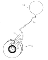
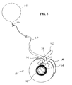
- FIG. 5 shows one embodiment of the present invention anchoring a balloon.
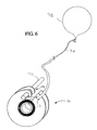
- FIG. 6 shows another embodiment of the present invention anchoring a balloon.
- FIGS. 1 and 2 illustrate one embodiment of the balloon anchor 10 of the present invention.
- the balloon anchor 10 has a spool 12 .
- the spool 12 may be hollow or solid. Attached to each side of the spool 12 are flanges 14 .
- the spool 12 is preferably cylindrical in shape, but may be any suitable shape.
- the spool 12 may have a notch 16 in one or both if its sides.
- the flanges 14 are preferably circular having a perimeter 18 .
- the flanges 14 are attached to each side of the spool 12 such that the spool 12 and flanges 14 have a common center point 20 .
- At least one of the flanges 14 have a cutout section 22 .
- This embodiment will be described with both flanges 14 having a cutout section 22 .
- Each cutout section 22 has a first side 24 that extends substantially along a radius from the center point 20 .
- Each cutout section 22 also has a second side 26 that extends substantially along a radius from the center point 20 .
- each hook 28 Extending from the second side 26 of each cutout section 22 is a hook 28 .
- Each hook 28 is generally U-shaped, and defines a base 30 and leg 32 .
- the leg 32 of each hook 28 extends inwardly, i.e., generally toward the center point 20 from the perimeters 18 of the flanges 14 . If both flanges 14 have a cutout section 22 , the hooks 28 of each flange 14 should be similarly oriented and in substantial registration with one another.
- the notch 16 is preferably located on one or both sides of the spool 12 within at least one cutout section 22 .
- a second notch 17 may be located along either one or both of the first side 24 or second side 26 , on the bases 30 , or on legs 32 .
- One or more notches 17 may also be located at any suitable point along the perimeter 18 of one or both flanges 14 .
- a ribbon 34 is wrapped around the spool 12 .
- the ribbon 34 has a first end (not shown) secured to the spool 12 by any suitable means, including taping the first end to the spool 12 .
- the first end of the ribbon 34 may also extend through the notch 16 and a knot tied in the first end of the ribbon 34 .
- the ribbon 34 also has a second end 36 that is attached to a balloon 38 .
- a ribbon is preferred, a string or any similar suitable material may be used.
- the balloon anchor 10 is preferably made of a plastic material, but may be any suitable material and size having sufficient mass to act as an anchor to overcome the buoyancy force of the balloon 38 .
- FIGS. 3 and 4 illustrate a second embodiment of the balloon anchor 42 of the present invention.
- balloon anchor 42 has a spool 44 and flanges 46 extending from each side of the spool 44 .
- the spool 44 is preferably cylindrical, but may be any suitable shape.
- the flanges 46 are preferably circular each having a perimeter 40 .
- the flanges 46 are attached to each side of the spool 44 such that the spool 44 and flanges 46 have a common center point 50 .
- At least one of the flanges 46 have a plurality of cutout sections 48 .
- This embodiment will be described with both flanges 46 having a plurality of cutout sections 48 .
- FIG. 3 shows an embodiment with four cutout sections 48 , though the invention contemplates any desired number of cutout sections 48 , depending on the size of the balloon anchor 42 .
- the multiple cutout sections 48 each have a first side 52 that extend substantially along a radius from the center point 50 .
- Each cutout section 48 also has a second side 54 that extends substantially along a radius from the center point 50 .
- each hook 56 Extending from each second side 54 of each cutout section 48 is a hook 56 .
- Each hook 56 is generally U-shaped and defines a base 58 and leg 60 .
- the leg 60 of each hook 56 extends inwardly, i.e., generally toward the center point 50 from the perimeter 40 of the flanges 46 . If both flanges 46 have cutout sections 48 , the hooks 56 of each flange 46 should be similarly oriented and in substantial registration with one another.
- a notch 62 may be located on one or both sides of the spool 44 within each cutout section 48 .
- a second notch 63 may be located along one or both of the first side 52 or second side 54 , on the base 58 , or on leg 60 .
- One or more notches 63 may also be located at any suitable point along the perimeter 40 of one or both flanges 46 .
- a ribbon 64 is wrapped around the spool 44 .
- the ribbon 64 has a first end (not shown) secured to the spool 44 by any suitable means, including taping the first end to the spool 44 .
- the first end of the ribbon 64 may also extend through the notch 62 and a knot tied in the first end of the ribbon 64 .
- the ribbon 64 also has a second end that is attached to a balloon as in FIGS. 5 and 6. While a ribbon is preferred, a string or any suitable material may be used.
- the balloon anchor 42 is preferably made of a plastic material, but may be any suitable material and size having sufficient mass to act as an anchor to overcome the buoyancy force of the balloon 38 .
- FIG. 5 shows one way in which the balloon anchor 10 secures a balloon 38 . It is contemplated that although FIGS. 5 and 6 are described with respect to the first embodiment of the balloon anchor 10 , the same principles apply to the second embodiment of the present invention 42 .
- the balloon anchor 10 is suspended by hooks 28 extending from each flange 14 around a peg 72 .
- the bases 30 of the hooks 28 rest on the peg 72 .
- the legs 32 of the hooks 28 wrap partially around the peg 72 .
- the peg 72 can be any suitable peg including a tack, nail, pin, or a wire.
- the ribbon 34 wrapped around the spool 12 is attached at its second end 36 to a balloon 38 .
- the ribbon 34 is wrapped around the spool 12 such that when the balloon anchor 10 is hung from the peg 72 , the ribbon 34 is impeded from extending by contact with the peg 72 , thus securing the balloon.
- FIG. 6 shows an alternative way in which the balloon anchor 10 secures a balloon 38 .
- the balloon anchor 10 of FIG. 6 is suspended on peg 72 by hooks 28 .
- the ribbon 34 is placed in the notch 17 , which prevents the ribbon 34 from extending, and secures the balloon.
- the notch 17 may be located along either the first side 24 or second side 26 , on the base 30 , or the leg 32 .
- the notch 17 may also be located at any suitable point along the perimeter 18 of one or both flanges 14 .
Abstract
Description
- The present invention relates to an anchor for fixedly tethering a balloon. Balloons, including lighter-than-air balloons, are well-known in the art. Lighter-than-air balloons are used for decorations at parties, given as gifts, and presented to persons with floral or other arrangements at special occasions such as graduations, birthdays, Valentine's Day, and Mothers' Day. Such balloons often bear an indicia of the occasion, such as “Happy Birthday,” “Over the Hill,” or “Congratulations.”
- Lighter-than-air balloons are typically filled with helium, but may be filled with any lighter-than-air gas. Thus, the balloons float in air. The balloons may be made from a variety of materials, including natural or synthetic rubber, polyester, metallized polyester, nylon, or metallized nylon. If untethered, the balloons would float uncontrolled.
- Often, for display in retail stores, balloon weights have been employed, with the balloon attached to the weight by a string or ribbon. Weights, however, may be unsightly, and string or ribbon must be tied to the weight. Balloons are also sometimes tied to any stable object to prevent them from floating away. Tying and untying balloons when a customer purchases them is time-consuming for the store clerk.
- Balloon weights have been developed that have a pre-assembled weight, a length of ribbon, and sometimes a means to attach the balloon to the ribbon. Examples of such weights are disclosed in U.S. Pat. Nos. 5,989,093 and 6,076,758. These prior art balloon weights often have hooks extending from them, and are adapted to be hung from a peg. The hooks have the potential to break off, thus defeating the purpose of the balloon weight. Moreover, extending the hook from the body of the weight increases difficulty in using automation to package such weights.
- The present invention provides a balloon anchor including a spool having opposing sides, a pair of flanges, one flange extending from each opposing side of the spool, one of the flanges having a cutout section, the cutout section having a first side and a second side, and a hook extending from the second side of the cutout section.
- In another embodiment, the balloon anchor has a spool having opposing sides, a pair of flanges, one flange extending from each opposing side of the spool, each flange having a cutout section, each cutout section having a first side and a second side, and a hook extending from the second side of each cutout section.
- A further embodiment of the balloon anchor includes a spool having opposing sides, a pair of flanges, one flange extending from each opposing side of the spool, each flange having a plurality of cutout sections, the cutout sections having a first side and a second side, and a hook extending from the second side of each cutout section.
- In a still further embodiment of the present invention, the balloon anchor has a spool having opposing sides, a pair of flanges, one flange extending from each opposing side of the spool, one of the flanges having a plurality of cutout sections, each cutout section having a first side and a second side, a hook extending from the second side of each cutout section.
- The balloon anchor of the present invention does not have an external hook. The hook of the present invention is located within the perimeter of the flange. Thus, the hook is less likely to break off during use, and is also more easily packaged using automation than weights having an extended hook. Additional features and advantages of the present invention are described in, and will be apparent from, the following Detailed Description of the Invention and the figures.
- FIG. 1 is a side view of one embodiment of the balloon anchor of the present invention.
- FIG. 2 is an end view of the balloon anchor of FIG. 1.
- FIG. 3 is a side view of another embodiment of the balloon anchor of the present invention.
- FIG. 4 is an end view of the balloon anchor of FIG. 3.
- FIG. 5 shows one embodiment of the present invention anchoring a balloon.
- FIG. 6 shows another embodiment of the present invention anchoring a balloon.
- FIGS. 1 and 2 illustrate one embodiment of the
balloon anchor 10 of the present invention. Theballoon anchor 10 has aspool 12. Thespool 12 may be hollow or solid. Attached to each side of thespool 12 areflanges 14. Thespool 12 is preferably cylindrical in shape, but may be any suitable shape. Thespool 12 may have anotch 16 in one or both if its sides. Theflanges 14 are preferably circular having aperimeter 18. Theflanges 14 are attached to each side of thespool 12 such that thespool 12 andflanges 14 have acommon center point 20. - At least one of the
flanges 14, but preferably bothflanges 14, have acutout section 22. This embodiment will be described with bothflanges 14 having acutout section 22. Eachcutout section 22 has afirst side 24 that extends substantially along a radius from thecenter point 20. Eachcutout section 22 also has asecond side 26 that extends substantially along a radius from thecenter point 20. - Extending from the
second side 26 of eachcutout section 22 is ahook 28. Eachhook 28 is generally U-shaped, and defines abase 30 andleg 32. Theleg 32 of eachhook 28 extends inwardly, i.e., generally toward thecenter point 20 from theperimeters 18 of theflanges 14. If bothflanges 14 have acutout section 22, thehooks 28 of eachflange 14 should be similarly oriented and in substantial registration with one another. Thenotch 16 is preferably located on one or both sides of thespool 12 within at least onecutout section 22. Preferably asecond notch 17 may be located along either one or both of thefirst side 24 orsecond side 26, on thebases 30, or onlegs 32. One ormore notches 17 may also be located at any suitable point along theperimeter 18 of one or bothflanges 14. - A
ribbon 34 is wrapped around thespool 12. Theribbon 34 has a first end (not shown) secured to thespool 12 by any suitable means, including taping the first end to thespool 12. The first end of theribbon 34 may also extend through thenotch 16 and a knot tied in the first end of theribbon 34. Theribbon 34 also has asecond end 36 that is attached to aballoon 38. (FIGS. 5 and 6.) While a ribbon is preferred, a string or any similar suitable material may be used. Theballoon anchor 10 is preferably made of a plastic material, but may be any suitable material and size having sufficient mass to act as an anchor to overcome the buoyancy force of theballoon 38. - FIGS. 3 and 4 illustrate a second embodiment of the
balloon anchor 42 of the present invention. Like the embodiment of FIGS. 1 and 2,balloon anchor 42 has aspool 44 andflanges 46 extending from each side of thespool 44. Thespool 44 is preferably cylindrical, but may be any suitable shape. Theflanges 46 are preferably circular each having aperimeter 40. Theflanges 46 are attached to each side of thespool 44 such that thespool 44 andflanges 46 have a common center point 50. - At least one of the
flanges 46, but preferably bothflanges 46, have a plurality ofcutout sections 48. This embodiment will be described with bothflanges 46 having a plurality ofcutout sections 48. FIG. 3 shows an embodiment with fourcutout sections 48, though the invention contemplates any desired number ofcutout sections 48, depending on the size of theballoon anchor 42. Themultiple cutout sections 48 each have afirst side 52 that extend substantially along a radius from the center point 50. Eachcutout section 48 also has asecond side 54 that extends substantially along a radius from the center point 50. - Extending from each
second side 54 of eachcutout section 48 is ahook 56. Eachhook 56 is generally U-shaped and defines abase 58 andleg 60. Theleg 60 of eachhook 56 extends inwardly, i.e., generally toward the center point 50 from theperimeter 40 of theflanges 46. If bothflanges 46 havecutout sections 48, thehooks 56 of eachflange 46 should be similarly oriented and in substantial registration with one another. Anotch 62 may be located on one or both sides of thespool 44 within eachcutout section 48. Alternatively, asecond notch 63 may be located along one or both of thefirst side 52 orsecond side 54, on thebase 58, or onleg 60. One ormore notches 63 may also be located at any suitable point along theperimeter 40 of one or bothflanges 46. - A
ribbon 64 is wrapped around thespool 44. Theribbon 64 has a first end (not shown) secured to thespool 44 by any suitable means, including taping the first end to thespool 44. The first end of theribbon 64 may also extend through thenotch 62 and a knot tied in the first end of theribbon 64. Theribbon 64 also has a second end that is attached to a balloon as in FIGS. 5 and 6. While a ribbon is preferred, a string or any suitable material may be used. Theballoon anchor 42 is preferably made of a plastic material, but may be any suitable material and size having sufficient mass to act as an anchor to overcome the buoyancy force of theballoon 38. - FIG. 5 shows one way in which the
balloon anchor 10 secures aballoon 38. It is contemplated that although FIGS. 5 and 6 are described with respect to the first embodiment of theballoon anchor 10, the same principles apply to the second embodiment of thepresent invention 42. During display, theballoon anchor 10 is suspended byhooks 28 extending from eachflange 14 around apeg 72. Thebases 30 of thehooks 28 rest on thepeg 72. Thelegs 32 of thehooks 28 wrap partially around thepeg 72. Thepeg 72 can be any suitable peg including a tack, nail, pin, or a wire. - The
ribbon 34 wrapped around thespool 12 is attached at itssecond end 36 to aballoon 38. Theribbon 34 is wrapped around thespool 12 such that when theballoon anchor 10 is hung from thepeg 72, theribbon 34 is impeded from extending by contact with thepeg 72, thus securing the balloon. - FIG. 6 shows an alternative way in which the
balloon anchor 10 secures aballoon 38. As in FIG. 5, theballoon anchor 10 of FIG. 6 is suspended onpeg 72 byhooks 28. In FIG. 6, theribbon 34 is placed in thenotch 17, which prevents theribbon 34 from extending, and secures the balloon. As stated above, thenotch 17 may be located along either thefirst side 24 orsecond side 26, on thebase 30, or theleg 32. Thenotch 17 may also be located at any suitable point along theperimeter 18 of one or bothflanges 14. - It should be understood that various changes and modifications to the presently preferred embodiments described herein will be apparent to those skilled in the art. Such changes and modifications can be made without departing from the spirit and scope of the present invention and without diminishing its intended advantages. It is therefore intended that such changes and modifications be covered by the appended claims.
Claims (32)
Priority Applications (3)
| Application Number | Priority Date | Filing Date | Title |
|---|---|---|---|
| US10/124,940 US7178754B2 (en) | 2002-04-17 | 2002-04-17 | Balloon anchor |
| AU2003221850A AU2003221850A1 (en) | 2002-04-17 | 2003-04-11 | Balloon anchor |
| PCT/US2003/011006 WO2003089099A2 (en) | 2002-04-17 | 2003-04-11 | Balloon anchor |
Applications Claiming Priority (1)
| Application Number | Priority Date | Filing Date | Title |
|---|---|---|---|
| US10/124,940 US7178754B2 (en) | 2002-04-17 | 2002-04-17 | Balloon anchor |
Publications (2)
| Publication Number | Publication Date |
|---|---|
| US20030197084A1 true US20030197084A1 (en) | 2003-10-23 |
| US7178754B2 US7178754B2 (en) | 2007-02-20 |
Family
ID=29214681
Family Applications (1)
| Application Number | Title | Priority Date | Filing Date |
|---|---|---|---|
| US10/124,940 Expired - Fee Related US7178754B2 (en) | 2002-04-17 | 2002-04-17 | Balloon anchor |
Country Status (3)
| Country | Link |
|---|---|
| US (1) | US7178754B2 (en) |
| AU (1) | AU2003221850A1 (en) |
| WO (1) | WO2003089099A2 (en) |
Cited By (4)
| Publication number | Priority date | Publication date | Assignee | Title |
|---|---|---|---|---|
| US20060199465A1 (en) * | 2005-03-03 | 2006-09-07 | Brent Anderson | Enhanced balloon weight system |
| US20110214258A1 (en) * | 2010-03-04 | 2011-09-08 | Kristi Lee Seymour | Safety device for corded window treatments |
| WO2013063606A1 (en) * | 2011-10-28 | 2013-05-02 | Berk Jed | Interactive entertainment device for lighter-than-air balloons |
| US11208280B2 (en) * | 2014-10-02 | 2021-12-28 | Timothy Briggs | Tape holder |
Families Citing this family (8)
| Publication number | Priority date | Publication date | Assignee | Title |
|---|---|---|---|---|
| US7850506B2 (en) * | 2006-06-07 | 2010-12-14 | Nelson David C | Balloon weight and method for presenting lighter-than-air balloons for retail sale |
| US9185903B2 (en) * | 2010-10-28 | 2015-11-17 | Carlo Paternostro | Decoy anchor assembly |
| US8485856B2 (en) * | 2010-10-28 | 2013-07-16 | Carlo Paternostro | Decoy anchor assembly |
| US8840440B2 (en) * | 2011-06-08 | 2014-09-23 | Express Dental Products, Inc. | Balloon holder |
| US20150230446A1 (en) * | 2014-02-08 | 2015-08-20 | Jeremy Omer Pollender | Device for securing line on spool or reel for storage |
| US9688496B2 (en) * | 2015-10-02 | 2017-06-27 | Michael Davin Godfrey | Mat rolling apparatatus and method |
| USD924650S1 (en) * | 2017-10-10 | 2021-07-13 | Lowrey Development Pty Ltd and Brands & Logos 4 Sale Pty Limited | Fencing tool |
| US11435072B1 (en) * | 2021-12-14 | 2022-09-06 | Hammerton, Inc. | Adjustable-length ceiling-mounted canopy for a lighting fixture |
Citations (12)
| Publication number | Priority date | Publication date | Assignee | Title |
|---|---|---|---|---|
| US2683937A (en) * | 1952-07-15 | 1954-07-20 | Lewis B Kingsley | Plumb bob adjuster |
| US4195794A (en) * | 1978-11-13 | 1980-04-01 | Grant John S | Reel holder with drag |
| US4779816A (en) * | 1985-10-11 | 1988-10-25 | Varlet Marc F | Cord winder |
| US4917323A (en) * | 1988-11-10 | 1990-04-17 | Don Wing | Christmas light storage device |
| US5255866A (en) * | 1990-10-19 | 1993-10-26 | Leviton Manufacturing Co., Inc. | Apparatus for isolating a cord section from tension |
| US5265822A (en) * | 1992-07-13 | 1993-11-30 | Shober Jr Robert C | IV tube support assembly |
| US5957401A (en) * | 1998-06-23 | 1999-09-28 | O'donnell; Patricia Sessum | Device for storing a string of lights |
| US6065709A (en) * | 1994-09-20 | 2000-05-23 | Innoessentials International B.V. | Cable storage reel |
| US6164582A (en) * | 1994-10-18 | 2000-12-26 | Reel Butler, Inc. | Enhanced storage system for electrical appliances, powercords and adapters |
| US6286777B1 (en) * | 1999-01-21 | 2001-09-11 | Stringliner Company | Extension cord storage and dispensing system |
| US6431489B1 (en) * | 2001-04-23 | 2002-08-13 | Michael L. Rose | Christmas light storage device |
| US6497381B2 (en) * | 2001-04-23 | 2002-12-24 | Michael L. Rose | Christmas light storage device |
Family Cites Families (19)
| Publication number | Priority date | Publication date | Assignee | Title |
|---|---|---|---|---|
| IT1163424B (en) * | 1982-11-25 | 1987-04-08 | Mitel Corp | ROPE STORAGE DEVICE |
| US4993664A (en) | 1989-04-24 | 1991-02-19 | Kneeland Howard A | Equilibrium ballast apparatus for lighter-than-air balloons and method for using same |
| US4936532A (en) | 1989-07-10 | 1990-06-26 | Jesse Williams | Balloon closure and hanger device |
| US5074510A (en) | 1989-08-17 | 1991-12-24 | Metz Kurt W | Balloon holders |
| US5035391A (en) | 1990-03-01 | 1991-07-30 | Steele Dennis M | Balloon anchor |
| US5240199A (en) | 1991-02-27 | 1993-08-31 | Peters William H | Balloon holding device |
| US5188314A (en) | 1991-04-08 | 1993-02-23 | Peters William H | Balloon holding device |
| US5259805A (en) | 1992-05-13 | 1993-11-09 | Anagram International, Inc. | Stabilized appendage for a novelty balloon product |
| US5797783A (en) | 1993-04-02 | 1998-08-25 | M & D Balloons, Inc. | Toy balloon packaging |
| US5411427A (en) | 1993-04-26 | 1995-05-02 | Premium Balloon Accessories | Balloon weight and latch assembly |
| US5628091A (en) | 1996-01-05 | 1997-05-13 | Mueller; Herbert | Balloon closure device |
| US5662510A (en) | 1996-03-20 | 1997-09-02 | 24Th And Dean, Inc. | Balloon anchor with sounder and display area |
| US5755419A (en) | 1996-05-21 | 1998-05-26 | Diane C. Gearhart | Balloon holder apparatus |
| US5989093A (en) | 1997-04-18 | 1999-11-23 | David C. Nelson | Balloon weight and ribbon assembly |
| USD401255S (en) | 1998-02-02 | 1998-11-17 | Burns Clark J | Balloon weight |
| USD415841S (en) | 1998-10-28 | 1999-10-26 | Anagram International, Inc. | Balloon weight |
| USD414222S (en) | 1998-10-28 | 1999-09-21 | Anagram International, Inc. | Balloon weight |
| US6076758A (en) | 1998-10-28 | 2000-06-20 | Anagram International, Inc. | Balloon weight |
| AU730421B1 (en) | 2000-04-03 | 2001-03-08 | John Deliu | Novelty apparatus |
-
2002
- 2002-04-17 US US10/124,940 patent/US7178754B2/en not_active Expired - Fee Related
-
2003
- 2003-04-11 AU AU2003221850A patent/AU2003221850A1/en not_active Abandoned
- 2003-04-11 WO PCT/US2003/011006 patent/WO2003089099A2/en not_active Application Discontinuation
Patent Citations (12)
| Publication number | Priority date | Publication date | Assignee | Title |
|---|---|---|---|---|
| US2683937A (en) * | 1952-07-15 | 1954-07-20 | Lewis B Kingsley | Plumb bob adjuster |
| US4195794A (en) * | 1978-11-13 | 1980-04-01 | Grant John S | Reel holder with drag |
| US4779816A (en) * | 1985-10-11 | 1988-10-25 | Varlet Marc F | Cord winder |
| US4917323A (en) * | 1988-11-10 | 1990-04-17 | Don Wing | Christmas light storage device |
| US5255866A (en) * | 1990-10-19 | 1993-10-26 | Leviton Manufacturing Co., Inc. | Apparatus for isolating a cord section from tension |
| US5265822A (en) * | 1992-07-13 | 1993-11-30 | Shober Jr Robert C | IV tube support assembly |
| US6065709A (en) * | 1994-09-20 | 2000-05-23 | Innoessentials International B.V. | Cable storage reel |
| US6164582A (en) * | 1994-10-18 | 2000-12-26 | Reel Butler, Inc. | Enhanced storage system for electrical appliances, powercords and adapters |
| US5957401A (en) * | 1998-06-23 | 1999-09-28 | O'donnell; Patricia Sessum | Device for storing a string of lights |
| US6286777B1 (en) * | 1999-01-21 | 2001-09-11 | Stringliner Company | Extension cord storage and dispensing system |
| US6431489B1 (en) * | 2001-04-23 | 2002-08-13 | Michael L. Rose | Christmas light storage device |
| US6497381B2 (en) * | 2001-04-23 | 2002-12-24 | Michael L. Rose | Christmas light storage device |
Cited By (6)
| Publication number | Priority date | Publication date | Assignee | Title |
|---|---|---|---|---|
| US20060199465A1 (en) * | 2005-03-03 | 2006-09-07 | Brent Anderson | Enhanced balloon weight system |
| US7674152B2 (en) | 2005-03-03 | 2010-03-09 | Cti Industries, Inc. | Enhanced balloon weight system |
| US20110214258A1 (en) * | 2010-03-04 | 2011-09-08 | Kristi Lee Seymour | Safety device for corded window treatments |
| WO2013063606A1 (en) * | 2011-10-28 | 2013-05-02 | Berk Jed | Interactive entertainment device for lighter-than-air balloons |
| US9254445B2 (en) | 2011-10-28 | 2016-02-09 | Jed Berk | Interactive entertainment device for lighter-than-air balloons |
| US11208280B2 (en) * | 2014-10-02 | 2021-12-28 | Timothy Briggs | Tape holder |
Also Published As
| Publication number | Publication date |
|---|---|
| AU2003221850A1 (en) | 2003-11-03 |
| WO2003089099A2 (en) | 2003-10-30 |
| US7178754B2 (en) | 2007-02-20 |
Similar Documents
| Publication | Publication Date | Title |
|---|---|---|
| US7178754B2 (en) | Balloon anchor | |
| US5035391A (en) | Balloon anchor | |
| US5755419A (en) | Balloon holder apparatus | |
| JP3503900B2 (en) | Bouquet display equipment | |
| US4589854A (en) | Nested balloon holder | |
| US8152588B2 (en) | Balloon holder for helium and air-filled balloons | |
| US5797783A (en) | Toy balloon packaging | |
| US6716083B1 (en) | Balloon weight | |
| US4936532A (en) | Balloon closure and hanger device | |
| US20050121582A1 (en) | Decorative gift bag balloon Holder | |
| US6076758A (en) | Balloon weight | |
| US7708616B2 (en) | Balloon display systems | |
| US20070007424A1 (en) | Helium balloon ribboned mounting stick | |
| US20060223411A1 (en) | Lighter than air novelty figure | |
| US6582272B1 (en) | Balloon weight and ribbon assembly | |
| US5799377A (en) | Balloon neck closure and decoration apparatus | |
| US4253266A (en) | Collapsible and reusable pinata | |
| US6688939B1 (en) | Decorative balloon holder | |
| US5989093A (en) | Balloon weight and ribbon assembly | |
| US5938154A (en) | Balloon bouquet holder | |
| US6050874A (en) | Balloon coupling strip | |
| US6364733B1 (en) | Display balloon kit and method of assembly | |
| US6171166B1 (en) | Interlocking chamber pi{tilde over (n)}ata | |
| GB2379619A (en) | Clip for sealing a balloon. | |
| US6540578B1 (en) | Toy balloon |
Legal Events
| Date | Code | Title | Description |
|---|---|---|---|
| AS | Assignment |
Owner name: COLE TAYLOR BANK, ILLINOIS Free format text: SECURITY INTEREST;ASSIGNORS:CTI INDUSTRIES CORPORATION;CTI HELIUM, INC.;REEL/FRAME:014934/0051 Effective date: 20031231 |
|
| AS | Assignment |
Owner name: CTI INDUSTRIES CORPORATION, ILLINOIS Free format text: ASSIGNMENT OF ASSIGNORS INTEREST;ASSIGNOR:ANDERSON, BRENT;REEL/FRAME:015197/0797 Effective date: 20020415 |
|
| AS | Assignment |
Owner name: HARRIS N.A.,ILLINOIS Free format text: SECURITY AGREEMENT;ASSIGNOR:CTI INDUSTRIES CORPORATION;REEL/FRAME:024320/0317 Effective date: 20100429 Owner name: HARRIS N.A., ILLINOIS Free format text: SECURITY AGREEMENT;ASSIGNOR:CTI INDUSTRIES CORPORATION;REEL/FRAME:024320/0317 Effective date: 20100429 |
|
| FPAY | Fee payment |
Year of fee payment: 4 |
|
| FEPP | Fee payment procedure |
Free format text: PAT HOLDER CLAIMS SMALL ENTITY STATUS, ENTITY STATUS SET TO SMALL (ORIGINAL EVENT CODE: LTOS); ENTITY STATUS OF PATENT OWNER: SMALL ENTITY |
|
| AS | Assignment |
Owner name: BMO PRIVATE EQUITY (U.S.), INC., ILLINOIS Free format text: SECURITY AGREEMENT;ASSIGNOR:CTI INDUSTRIES CORPORATION;REEL/FRAME:028584/0400 Effective date: 20120717 |
|
| AS | Assignment |
Owner name: CTI INDUSTRIES CORPORATION, ILLINOIS Free format text: RELEASE BY SECURED PARTY;ASSIGNOR:COLE TAYLOR BANK;REEL/FRAME:029640/0128 Effective date: 20120731 |
|
| REMI | Maintenance fee reminder mailed | ||
| LAPS | Lapse for failure to pay maintenance fees | ||
| STCH | Information on status: patent discontinuation |
Free format text: PATENT EXPIRED DUE TO NONPAYMENT OF MAINTENANCE FEES UNDER 37 CFR 1.362 |
|
| FP | Lapsed due to failure to pay maintenance fee |
Effective date: 20150220 |
|
| AS | Assignment |
Owner name: CTI INDUSTRIES CORPORATION, ILLINOIS Free format text: RELEASE BY SECURED PARTY;ASSIGNOR:BMO HARRIS BANK N.A. (FORMERLY KNOWN AS HARRIS N.A.);REEL/FRAME:044402/0764 Effective date: 20171214 |