US20030197512A1 - Battery analyzer - Google Patents
Battery analyzer Download PDFInfo
- Publication number
- US20030197512A1 US20030197512A1 US10/131,794 US13179402A US2003197512A1 US 20030197512 A1 US20030197512 A1 US 20030197512A1 US 13179402 A US13179402 A US 13179402A US 2003197512 A1 US2003197512 A1 US 2003197512A1
- Authority
- US
- United States
- Prior art keywords
- battery
- information
- arrangement
- analyzer according
- user
- Prior art date
- Legal status (The legal status is an assumption and is not a legal conclusion. Google has not performed a legal analysis and makes no representation as to the accuracy of the status listed.)
- Abandoned
Links
Images


Classifications
-
- G—PHYSICS
- G01—MEASURING; TESTING
- G01R—MEASURING ELECTRIC VARIABLES; MEASURING MAGNETIC VARIABLES
- G01R31/00—Arrangements for testing electric properties; Arrangements for locating electric faults; Arrangements for electrical testing characterised by what is being tested not provided for elsewhere
- G01R31/36—Arrangements for testing, measuring or monitoring the electrical condition of accumulators or electric batteries, e.g. capacity or state of charge [SoC]
- G01R31/3644—Constructional arrangements
- G01R31/3648—Constructional arrangements comprising digital calculation means, e.g. for performing an algorithm
-
- G—PHYSICS
- G01—MEASURING; TESTING
- G01R—MEASURING ELECTRIC VARIABLES; MEASURING MAGNETIC VARIABLES
- G01R31/00—Arrangements for testing electric properties; Arrangements for locating electric faults; Arrangements for electrical testing characterised by what is being tested not provided for elsewhere
- G01R31/36—Arrangements for testing, measuring or monitoring the electrical condition of accumulators or electric batteries, e.g. capacity or state of charge [SoC]
- G01R31/374—Arrangements for testing, measuring or monitoring the electrical condition of accumulators or electric batteries, e.g. capacity or state of charge [SoC] with means for correcting the measurement for temperature or ageing
-
- G—PHYSICS
- G01—MEASURING; TESTING
- G01R—MEASURING ELECTRIC VARIABLES; MEASURING MAGNETIC VARIABLES
- G01R31/00—Arrangements for testing electric properties; Arrangements for locating electric faults; Arrangements for electrical testing characterised by what is being tested not provided for elsewhere
- G01R31/36—Arrangements for testing, measuring or monitoring the electrical condition of accumulators or electric batteries, e.g. capacity or state of charge [SoC]
- G01R31/382—Arrangements for monitoring battery or accumulator variables, e.g. SoC
- G01R31/3842—Arrangements for monitoring battery or accumulator variables, e.g. SoC combining voltage and current measurements
Definitions
- the present invention relates to battery analyzers and battery chargers.
- Battery adapters and analyzers permit a user to charge, discharge, and test the performance of a rechargeable battery.
- conventional adapters and analyzers cannot communicate information concerning the battery to a device in a remote location.
- conventional adapters and analyzers may not be used to communicate information to a device in a remote location, such as product orders, user inquiries, and/or user requests.
- a battery analyzer which includes a network interface arrangement configured to communicatively couple to a computer network, a battery interface arrangement configured to electrically connect to at least one battery arrangement, each of the at least one battery arrangement including at least one battery, and a processing arrangement electrically and communicatively coupled to the network interface arrangement and the battery interface arrangement, in which the processing arrangement is configured to communicate first information concerning the at least one battery to at least one remote device via the computer network.
- a battery analyzer which includes a network interface arrangement configured to communicatively couple to a computer network, a battery interface arrangement configured to electrically connect to at least one battery arrangement, each of the at least one battery arrangement including a battery, and a processing arrangement electrically and communicatively coupled to the network interface arrangement and the battery interface arrangement, in which the processing arrangement is configured to communicate first information concerning a diagnosis of the at least one battery to at least one remote device via the computer network.
- a battery analyzer which includes a network interface arrangement configured to communicatively couple to a computer network, a battery interface arrangement configured to electrically connect to at least one battery arrangement, each of the at least one battery arrangement including a battery, and a processing arrangement electrically and communicatively coupled to the network interface arrangement and the battery interface arrangement, in which the processing arrangement is configured to control at least one of a charging and a discharging of the at least one battery as a function of information received from at least one remote device via the network interface.
- a battery analyzer system which includes a computer network, a battery analyzer including a network interface arrangement communicatively coupled to the computer network, a battery interface arrangement configured to electrically connect to at least one battery arrangement, each of the at least one battery arrangement including a battery, and a processing arrangement electrically and communicatively coupled to the network interface arrangement and the battery interface arrangement, and at least one remote device communicatively coupled to the computer network; wherein the processing arrangement of the battery analyzer is configured to communicate first information concerning the at least one battery to the least one remote device via the computer network.
- a customer service site which includes a network interface arrangement configured to communicatively couple to a computer network, and a processing arrangement electrically and communicatively coupled to the network interface arrangement, in which the processing arrangement is configured to communicate first information concerning the at least one battery to the at least one battery analyzer via the computer network, and the processing arrangement is further configured to receive second information concerning at least one battery from at least one battery analyzer via the computer network.
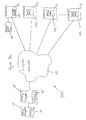
- FIG. 1 illustrates a battery analyzer system according to the present invention.
- FIG. 2 a illustrates another exemplary battery analyzer system of the type illustrated in FIG. 1, in which a selected one of at least one remote device includes a centralized computer for collecting and distributing information to a customer service site.
- FIG. 2 b is a flow diagram of data communication between the battery analyzer and the customer service site illustrated in FIG. 2 a.
- FIG. 2 c is a flow diagram of data communication between the battery analyzer and the customer service site illustrated in FIG. 2 a, in which the usage, performance, and technical support information indicate that the battery analyzer and/or the battery arrangement is defective.
- FIG. 3 a illustrates another exemplary battery analyzer system of the type illustrated in FIG. 2, in which the at least one remote device includes a centralized computer and a plurality of additional battery analyzers.
- FIG. 3 b illustrates the exemplary battery analyzer system of FIG. 3 a, in which the at least one remote device includes at least one respective battery analyzer.
- FIG. 4 a is an illustration the battery analyzer of FIGS. 1, 2 a, 3 a, and 3 b.
- FIG. 4 b illustrates the electrical connectivity between the battery arrangement of FIG. 4 a and a battery analyzer.
- FIG. 5 illustrates an exemplary embodiment of a battery adapter according to the present invention.
- FIG. 6 is a block diagram of the battery analyzer illustrated in FIGS. 1, 2 a, 3 a, and 3 b.
- FIG. 7 a illustrates further detail of the exemplary battery interface arrangement of FIG. 6.
- FIG. 7 b illustrates further detail of a variant of the battery interface arrangement of FIG. 6 operable to communicatively couple to a smart battery.
- FIG. 8 illustrates further detail of the reverse-battery protection arrangement of FIGS. 7 a and 7 b.
- FIG. 9 illustrates further detail of the exemplary processing arrangement of FIG. 6.
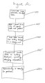
- FIG. 10 is a flow diagram of an exemplary performance sequence executed by the processing arrangement.
- FIG. 11 is a block diagram of an operational sequence for charging a battery.
- FIG. 12 is a block diagram of an operational sequence for discharging a battery.
- FIG. 13 is a block diagram of an operational sequence for replacing program code of a battery arrangement.
- FIG. 14 is a block diagram of data communication between the battery analyzer and a remote device.
- the battery analyzer system 100 includes a battery analyzer 105 having a user interface 135 and a battery arrangement 120 including at least one rechargeable battery 130 .
- the battery arrangement 120 is electrically coupled to the battery analyzer 105 .
- the battery analyzer 105 is communicatively coupled to at least one remote device 115 a, 115 b, 115 c, . . . , 115 n through a computer network 110 .
- the computer network 110 may include any conventional arrangement operable to communicatively couple the battery analyzer 105 to the remote device 115 a, 115 b, 115 c, . . . , 115 n, such as a dedicated point-to-point network, a token-ring network, a Wide Area Network (WAN), a Local Area Network (LAN), an intranet, an internet, and/or the Internet. Furthermore, each of the battery analyzer 105 and the remote devices 115 a, 115 b, 115 c, . . . , 115 n may be operable to communicatively couple to the computer network 110 by a hardwired connection (e.g., fiber optic cables and/or conductive cables) and/or by a wireless connection.
- a hardwired connection e.g., fiber optic cables and/or conductive cables
- the battery analyzer 105 is operable to evaluate the battery 130 and to determine, for example, usage and performance information concerning the battery 130 .
- the battery analyzer 105 may then communicate the usage and performance information, such as information indicating that the battery is not performing correctly, to one or more of the remote devices 115 a, 115 b, 115 c, . . . , 115 n via the computer network 110 .
- the battery analyzer 105 may also communicate data related to technical support, which may include charging and discharging parameters used in configuring the power management controller.
- Technical support data could also include, for example, software update information, information to allow the remote location to change parameters, or automated software update if an outdated software version is detected.
- the battery analyzer 105 is further operable to communicate user information, such as product order information, to one or more of the remote devices 115 a, 115 b, 115 c, . . . , 115 n in accordance with input data received from a user via the user interface 135 .
- Each of the remote devices 115 a, 115 b, 115 c, . . . , 115 n may include, for example, a respective centralized computer (not shown) operable to communicate information to the battery analyzer 105 , such as marketing information, software updates for the battery analyzer 105 and/or the battery arrangement 120 , user manuals, technical support data, product catalog information, battery specifications data, advertising information, and/or parameter information, such as battery charging and/or discharging parameters.
- Information received by the battery analyzer 105 may be displayed to a user of the battery analyzer 105 via the user interface 135 . Further, the marketing and/or advertising information may be generated in accordance with the usage and performance information concerning the battery 130 received from the battery analyzer 105 .
- the battery analyzer 105 and/or the remote device 115 a, 115 b, 115 c, . . . , 115 n may inform the user, for example, if the battery 130 needs to be replaced or if the battery 130 is not operating properly.
- one of the remote devices 115 a, 115 b, 115 c, . . . , 115 n includes a centralized computer system 205 for collecting and distributing information to a customer service site 210 .
- the customer service site 210 may be owned and controlled by any entity, for example, an individual, a manufacturer of the battery analyzer 105 , and/or a retailer or wholesaler of the battery analyzer 105 .
- the customer service site 210 may be located at the remote device 115 a, 115 b, 115 c, . . .
- the customer service site 210 may execute on the remote device 115 a, 115 b, 115 c, . . . , 115 n .
- the customer service site 210 may be separated from the remote device 115 a, 115 b, 115 c, . . . , 115 n and connected to the remote device 115 a, 115 b, 115 c, . . . , 115 n , for example, via a computer network.
- the functionality of the customer service site 210 and/or the computer system 205 may be distributed across any number of processing units.
- step 250 the battery analyzer 105 communicates, for example, usage, performance, and/or technical support information of the battery arrangement 120 to the customer service site 210 via the computer network 110 .
- This step may be initiated manually by the user, automatically by the battery analyzer 105 (e.g., at preselected intervals), and/or automatically by the customer service site 210 via the computer network 110 .
- the centralized computer system 205 may, for example, alert the customer service site 210 of specific needs and/or problems associated with the battery analyzer 105 and/or the battery arrangement 120 (e.g., usage trends, defective batteries, etc), based at least in part, for example, on the usage, performance, and/or technical support information received from the battery analyzer 105 .
- the usage, performance, and/or technical support information, as well as any other additional information transmitted by the battery analyzer 105 may be appropriately stored by the centralized computer system 205 in a memory unit (not shown) for subsequent retrieval, for example, to graph the usage and performance information and/or to perform numerical analysis on the usage and performance information.
- the customer support site 210 may then communicate data to the battery analyzer 105 via the centralized computer system 205 and the computer network 110 in accordance with the usage, performance, and/or technical support information received from the battery analyzer 105 .
- the customer service site 210 may communicate, for example, a product catalog of batteries and/or accessories to the battery analyzer 105 to be displayed to the user via the user interface 135 .
- the user may optionally order, for example, replacement batteries and/or accessories from the product catalog of batteries and/or accessories via the user interface 135 .
- the order may be communicated to the customer support site 210 via the computer network 110 , for example.
- the customer support site 210 may then cause the replacement batteries and/or accessories to be packaged and shipped to the user, as represented by step 275 .
- the customer service site 210 may communicate, for example, debugging information to the battery analyzer 105 to be displayed to the user via the user interface 135 .
- the user may diagnose and fix various problems associated with the battery analyzer 105 and/or the battery arrangement 120 , as represented by step 280 .
- the customer service site 210 may debug the battery analyzer 105 and/or the battery arrangement 120 automatically and without intervention by the user. For example, if analyzer software stored in the battery analyzer 105 is defective, the customer service site 210 may communicate and automatically replace the analyzer software with replacement software via the computer network 110 . Moreover, the customer service site 210 may communicate updated software and parameter information (including, for example, battery charging and/or discharging parameters) to the battery analyzer 105 .
- updated software and parameter information including, for example, battery charging and/or discharging parameters
- the centralized computer system 205 may directly control the battery analyzer 105 via the computer network 110 .
- the centralized computer system 205 may control, for example, the charging and/or discharging of the battery arrangement 120 , the performance evaluation of the battery arrangement 120 , the usage evaluation of the battery arrangement 120 , the conditioning of the battery arrangement 120 , and/or any other function of the battery analyzer 105 .
- FIG. 3 a there is seen another exemplary battery analyzer system 300 , in which one of the remote devices 115 a, 115 b, 115 c, . . . , 115 n includes a centralized computer system 205 and a plurality of additional battery analyzers 305 b, 305 c, . . . , 305 n.
- information such as usage, performance, and/or technical support information, may be transmitted between the battery analyzers 105 and/or 305 b, 305 c, . . . , 305 n and/or between one or more battery analyzers 105 and/or 305 b, 305 c, .
- the centralized computer system 205 may communicate marketing information, software updates for the battery analyzer 105 , user manuals, technical support data, product catalog information, battery specifications data, charging/discharging parameters and/or advertising information selectively to a single one of battery analyzers 105 and 305 b, 305 c, . . . , 305 n, a group of two or more of battery analyzers 105 and 305 b, 305 c, . . . , 305 n, or to all of battery analyzers 105 and 305 b, 305 c, . . . , 305 n.
- each of the battery analyzers 105 and 305 b, 305 c, . . . , 305 n and the centralized computer system 205 may be assigned a unique, respective network address for identification over the computer network 110 .
- FIG. 3 b illustrates the exemplary battery analyzer system 300 of the FIG. 3 a, in which each of the remote devices 115 a, 115 b, 115 c, . . . , 115 n includes at least one respective battery analyzer 305 a, 305 b, 305 c, . . . , 305 n.
- any one of the battery analyzers 105 and 305 a, 305 b, 305 c, . . . , 305 n may perform functions similar to those described above with respect to the centralized computer system 205 .
- any one of the battery analyzers 105 and 305 a, 305 b, 305 c, . . . , 305 n may communicate information, such as user manuals, technical support data, product catalog information, battery specifications data, battery charging/discharging parameters and/or advertising information. Further, any one of the battery analyzers 105 and 305 a, 305 b, 305 c, . . . , 305 n may troubleshoot and/or directly control one or more of the other battery analyzers 105 and 305 a, 305 b, 305 c, . . . , 305 n.
- FIG. 4 a there is seen an illustration of the battery analyzer 105 of FIGS. 1, 2 a, 3 a, and 3 b.
- the battery analyzer 105 is electrically connected to and receives power from an external power source (not shown).
- the battery analyzer 105 includes a base unit 405 having a user interface 415 and a battery interface arrangement 410 including at least one port 420 .
- Each of the ports 420 is suitably configured to releaseably and electrically couple to a respective battery arrangement 120 .
- each of the ports 420 of the battery analyzer 105 includes an analyzer connector 425 having a plurality of conductive contacts 435 , which electrically couple to the battery arrangement 120 when the battery arrangement 120 is lowered into one of the ports 420 . At least two of the conductive contacts 435 are provided to charge and/or discharge the battery 130 of the battery arrangement 120 .
- the battery arrangement 120 is lowered into one of the ports 420 in a first direction 430 , whereby the conductive contacts 435 of the battery analyzer 105 electrically couple to the battery arrangement 120 .
- the user interface 415 of the battery analyzer 105 may communicate, for example, status information to the user concerning one or more of the ports 420 .
- the user interface 415 may indicate whether one or more of the ports 420 are receiving power from the external power source and/or whether the battery arrangement 120 is charging in one of the ports 420 .
- the user interface 415 may also indicate the amount of power (i.e., charge) that is maintained by a battery 130 of the battery arrangement 120 .
- FIG. 4 b there is seen an illustration showing the electrical connectivity between the battery arrangement 120 of FIG. 4 a and the battery analyzer 105 .
- the conductive contacts 435 of the battery analyzer 105 electrically contact a plurality of conductive contacts 440 of the battery arrangement 120 .
- power is received from the external power source (not shown) and provided to the analyzer connector 425 of one or more of the ports 420 , including the port 420 to which the battery arrangement 120 is coupled, thereby providing the power to the battery 130 of the battery arrangement 120 .
- the conductive contacts 435 of the battery analyzer 105 may be used, for example, to facilitate data communication between the battery analyzer 105 and the battery arrangement 120 .
- the battery analyzer 105 may instruct the battery arrangement 120 to charge and/or discharge the battery 130 , if the battery arrangement 120 includes an arrangement, for example, a battery adapter, capable of charging and/or discharging the battery 130 .
- the battery arrangement 120 may include a battery 130 and/or a battery adapter having a battery 130 , as described in U.S. Patent Application attorney docket No. 02520/49401 entitled “Battery Adapter,” filed concurrently herewith and expressly incorporated herein by reference.
- FIG. 5 illustrates an exemplary battery adapter 450 .
- Battery adapter 450 includes a base unit 452 , battery holder 454 , and a circuit arrangement (not shown).
- the battery holder 454 is connected to base unit 452 and has a receptacle portion 456 for receiving the battery 130 .
- the receptacle portion 456 of the battery holder 454 may be pre-configured to receive various types of batteries, such as nickel cadmium batteries, nickel metal-hydride batteries, lithium batteries, etc.
- the external surface 458 of the battery 130 has a smaller geometry than the geometry of an external surface 460 of the battery holder 454 .
- the battery 130 may be inserted into the receptacle portion 456 , for charging and/or discharging.
- the battery adapter 450 includes a first adapter contact 462 and a second adapter contact 464 .
- the first and second adapter contacts 462 , 464 may be provided, for example, in the base unit 452 , in the battery holder 454 or separately therebetween.
- the first adapter contact 462 is provided for conductively connecting to a first battery contact 466 of the battery 130
- the second adapter contact 464 is provided for conductively connecting to a second battery contact 468 of the battery 130 .
- the first and second adapter contacts 462 , 464 of the battery adapter 450 electrically connect to the respective first and second battery contacts 466 , 468 of the battery 130 .
- Battery analyzer 105 includes a base unit 605 .
- the base unit 605 has a battery interface arrangement 610 configured to electrically couple to one or more battery arrangements 120 , a user interface arrangement 615 configured to communicate user information to a user 635 and for receiving user input data from the user 635 , a network interface arrangement 620 configured to communicatively couple to the computer network 110 , a power delivery arrangement 625 configured to receive power from an external power source 640 and providing said power to the battery analyzer 105 via internal power connections 650 a, 650 b, 650 c, 650 d, and a processing arrangement 630 .
- the battery interface arrangement 610 , the user interface arrangement 615 , the network interface arrangement 620 , and the processing arrangement 630 are electrically and communicatively coupled to one another via data bus 645 .
- Network interface arrangement 620 includes circuitry operable to communicatively couple to the computer network 110 .
- network interface arrangement 620 may include circuitry operable to communicatively couple to an ethernet, a token-ring network, a dedicated point-to-point network, a WAN, a LAN, an intranet, an internet, and/or the Internet.
- the network interface arrangement 420 of the battery analyzer 105 may be assigned a unique network address, which uniquely identifies the battery analyzer 105 over the computer network 110 , with respect to the remote devices 115 a, 115 b, 115 c, . . . , 115 n.
- each of the remote devices 115 a, 115 b, 115 c, . . . , 115 n includes network interface circuitry and a unique network address similar to those of the network interface arrangement 620 of the battery analyzer 105 . This permits the battery analyzer 105 to selectively communicate with one or any number of the remote devices 115 a, 115 b, 115 c, . . . , 115 n via the computer network 110 .
- the network interface arrangement 620 is operable to receive data from one or more of the remote devices 115 a, 115 b, 115 c, . . . , 115 n via the computer network 110 and to provide the data to the processing arrangement 630 via the data bus 645 .
- the data may include, for example, marketing information, software updates for the battery analyzer 105 and/or for the battery arrangement 120 , user manuals, technical support data, product catalog information, battery specifications data, advertising information, and/or parameter data including, for example, charging and/or discharging parameters for a battery.
- the network interface arrangement 620 is also operable to receive data from the processing arrangement 630 via the data bus 645 and to communicate the data to the one or more of the remote devices 115 a, 115 b, 115 c, . . . , 115 n via the computer network 110 .
- the data may include, for example, usage, performance, and/or technical support information concerning the battery 130 of the battery arrangement 120 and/or user information, such as battery and accessory orders.
- the analyzer connector 705 includes a plurality of conductive contacts operable to electrically couple to the plurality of conductive contacts 440 of the battery arrangement 120 .
- the conductive contacts of the analyzer connector 705 include battery interface contacts 730 , data interface contacts 775 , and a tri-state data contact 725 .
- FIG. 7 a illustrates a single battery arrangement 120
- the battery interface arrangement 610 may be operable to electrically couple to a plurality of battery arrangements, each of which includes a respective battery, which may be of a different type (e.g., a nickel cadmium battery, a nickel metal-hydride battery, a lithium ion battery, etc.).
- Battery interface arrangement 610 includes a data communications arrangement 780 , a charge/discharge arrangement 765 , a reverse-battery protection arrangement 770 , a current sensing arrangement 715 , a voltage sensing arrangement 720 , and a chemistry sensing arrangement 710 .
- Each of the reverse-battery protection arrangement 770 , the current sensing arrangement 715 , and the voltage sensing arrangement 720 is electrically coupled to the first and second adapter contacts 462 , 464 of the battery arrangement 120 via the battery interface contacts 730 of the analyzer connector 705 .
- the first and second adapter contacts 462 , 464 electrically contact the first and second battery contacts 466 , 468 when the battery 130 is received by the battery arrangement 120 .
- the data communications arrangement 780 is electrically and communicatively coupled to the battery arrangement 120 via the data interface contacts 775 .
- the chemistry sensing arrangement 710 is electrically and communicatively coupled to the battery arrangement 120 via the tri-state logic data contact 725 .
- the charge/discharge arrangement 765 is electrically coupled to the reverse-battery protection arrangement 770 . Additionally, each of the data communications arrangement 780 , the charge/discharge arrangement 765 , the current sensing arrangement 715 , the voltage sensing arrangement 720 , and the chemistry sensing arrangement 710 is electrically and communicatively coupled to the data bus 645 .
- the data communications arrangement 780 includes circuitry operable to electrically and communicatively couple to the battery arrangement 120 .
- the data communications arrangement 780 permits data to be communicated to the battery arrangement 120 by the processing arrangement 630 of the battery analyzer 105 and/or permits data to be communicated to the processing arrangement 630 of the battery analyzer 105 from the battery arrangement 120 .
- the processing arrangement 630 may, for example, reconfigure the battery adapter 450 by communicating updated program code to be executed by a micro-computer situated in the battery adapter 450 .
- the processing arrangement 630 may also communicate parameter data relating to, for example, charging and/or discharging of a battery 130 of the battery arrangement 120 .
- the processing arrangement 630 communicates the updated program code and/or the parameter data to the data communications arrangement 780 via the data bus 645 , and the data communications arrangement 780 then communicates the updated program code to the battery arrangement 120 via the data interface contacts 775 of the analyzer connector 705 .
- the battery adapter 450 may also, for example, communicate usage and performance information concerning the battery 130 to the processing arrangement 630 .
- the battery adapter 450 communicates the usage and performance information to the data communications arrangement 780 via the data interface contacts 775 , and the data communications arrangement 780 then communicates the usage and performance information to the processing arrangement 630 via the data bus 645 .
- the charge/discharge arrangement 765 includes circuitry operable to charge and/or discharge the battery 130 of the battery arrangement 120 via the battery interface contacts 730 of the analyzer connector 705 .
- the charge/discharge arrangement 765 is controlled by the processing arrangement 630 via the data bus 645 as more fully described below.
- the charge/discharge arrangement 765 may employ a combination of constant voltage control (CV) and constant current control (CV), in accordance with the chemistry of battery 130 , such as, for example, nickel cadmium, nickel metal-hydride, lithium, etc. Each chemistry may utilize a unique combination of CV and CC control, that is, a unique charge profile.
- CV control the charge/discharge arrangement 765 provides a constant voltage across the first and second battery contacts 466 , 468 of the battery 130 . The constant voltage applied depends on a desired final charging voltage of the battery 130 .
- CV control applies a constant voltage of 5 volts across the first and second battery contacts 466 , 468 of the battery 130 .
- the constant voltage applied causes a large initial current to flow through (i.e., spike through) the first and second battery contacts 466 , 468 .
- CC control may be employed to effectively limit the maximum amount of current fed to the charging battery 130 .
- the voltage of the battery 130 approaches the constant voltage applied by the charge/discharge arrangement 765 , thereby causing the current flowing through the first and second battery contacts 466 , 468 of the battery 130 to decrease.
- the charge/discharge arrangement 765 ceases charging the battery 130 .
- the charge/discharge arrangement 765 short-circuits the battery contacts 466 , 468 of the battery 130 to ground through a low-resistance conductive path.
- the lower the resistance of the path to ground the faster the battery 130 will discharge.
- the charge/discharge arrangement 765 may include a large heat sink and/or fan (not shown) to dissipate the energy and heat generated by the discharging battery 130 .
- the reverse battery protection arrangement 770 prevents the battery 130 from being damaged, such as if the battery 130 is improperly inserted into the battery arrangement 120 or if the battery arrangement 120 is improperly inserted into the battery analyzer 105 (this may generate a short circuit, an overload, etc.).
- the reverse battery protection arrangement 770 may also prevent any such damage to the battery analyzer 105 .
- the current sensing arrangement 715 and the voltage sensing arrangement 720 include circuitry operable for detecting the current and voltage across the first and second battery contacts 466 , 468 of the battery 130 , respectively.
- the current sensing arrangement 715 and the voltage sensing arrangement 720 communicate the sensed voltage and sensed current to the processing arrangement 630 via the data bus 645 .
- the chemistry sensing arrangement 710 includes circuitry operable to detect the chemistry of the battery 130 , such as, for example, a nickel cadmium battery, a nickel metal-hydride battery, a lithium battery, etc.
- the chemistry sensing arrangement 710 may include electrical circuitry operable to connect to the tri-state logic data line 725 , which may be provided by battery arrangement 120 .
- Tri-state logic data line 725 may include three discrete logical states, e.g., “high,” “low,” and “float”. Each state may be used to communicate a different chemistry.
- a “high” logic level may indicate that battery arrangement 120 includes a nickel metal-hydride battery
- a “low” may indicate that battery arrangement 120 includes a nickel cadmium battery
- a “float” may indicate that battery arrangement 120 includes a lithium battery.
- the chemistry detect arrangement 710 communicates the sensed chemistry of the battery 130 to the processing arrangement 630 for use in generating a desired charge profile and/or a performance sequence, as described more fully below.
- the current, voltage, and chemistry of the battery 130 are sensed and communicated to the processing arrangement 630 by the current sensing arrangement 715 , the voltage sensing arrangement 720 , and the chemistry sensing arrangement 710 of the battery interface arrangement 610 , respectively.
- certain types of batteries for example, “smart” batteries, include “smart” circuitry, capable of communicating digital information concerning the battery, such as current, voltage, and chemistry.
- This circuitry may include an internal micro-computer and a digital interface for communicating information with an external device, such as, battery analyzer 105 .
- any data communications protocol and/or specification may be used.
- the battery analyzer 105 may use the System Management Bus (SMBus) specification v.2.0 to communicate data back and forth between the “smart” battery.
- SMBus System Management Bus
- the SMBus specification defines a two-wire interface through which various components situated in different systems may communicate data between each other.
- a smart-battery communications protocol such as SMBus
- a device may provide manufacturer information, model part information, error information, and status information, as well as receive control parameters and configuration information.
- the battery interface arrangement 610 may include a smart-battery interface 735 electrically and communicatively coupled to the data bus 645 . As shown in FIG.
- the smart-battery interface 735 includes circuitry operable to electrically and communicatively couple to a battery arrangement 120 that includes a special data port 745 for communicating information concerning a smart-battery 740 to an external device, such as the smart-battery interface 735 of the battery interface arrangement 610 .
- the special data port 745 includes a plurality of data lines 750 for communicating information, such as the current flowing through the smart-battery 740 , the voltage across the first and second smart battery contacts 755 , 760 of the smart battery 740 , the chemistry of the smart-battery 740 , a serial number associated with the smart battery 740 , a model number associated with the smart-battery 740 , etc.
- the smart-battery interface 735 then communicates the received information, such as the current, voltage, and chemistry of the smart battery 740 , to the processing arrangement 630 via the data bus 645 for further processing as described below.
- the battery arrangement 120 may include current, voltage, and sensing arrangements and/or a smart-battery interface similar to those of the battery analyzer 105 .
- the battery arrangement 120 for example, the battery adapter 450 , may detect the current, voltage, and chemistry of the battery 130 and then provide the current, voltage, and chemistry of the battery 130 to the battery analyzer 105 via the data communications arrangement 780 of the battery interface arrangement 610 .
- the processing arrangement 30 may receive the current, voltage, and chemistry information without the need for the current sensing arrangement 715 , the voltage sensing arrangement 720 , the chemistry sensing arrangement 710 or the smart-battery interface 735 .
- the reverse battery protection arrangement 770 prevents the battery 130 of the battery arrangement 120 from being damaged and may also prevent any such damage to the battery analyzer 105 .
- the reverse battery protection arrangement 770 is electrically connected to the battery charge/discharge arrangement 765 via a first connection arrangement 805 .
- the reverse battery protection arrangement 770 also communicates with the battery arrangement 120 via a second connection arrangement 810 .
- the reverse battery protection arrangement 770 may include a first switch Q 1 , a second switch Q 2 , a first resistor R 1 , a second resistor R 2 and a fuse F 1 .
- fuse F 1 is not used, as the reverse battery protection features of the reverse battery protection arrangement 770 may provide sufficient protection without it.
- the first battery contact 466 of the battery 130 is conductively coupled to, e.g., a first terminal 815 of the reverse battery protection arrangement 770 via one of battery interface contacts 730 .
- the second battery contact 468 of the battery 130 is conductively coupled to a second terminal 820 of the reverse battery protection arrangement 770 .
- the first switch Q 1 is turned on because the voltage at a terminal B 1 of the first switch Q 1 is higher than the voltage at a terminal E 1 .
- a terminal G 1 enables the second switch Q 2 (i.e., switches on the second switch Q 2 ), and thus the current flows between a terminal D 1 and a terminal S 1 of the second switch Q 2 .
- the first switch Q 1 is turned off because the voltage at the terminal B 1 of the first switch Q 1 is lower than the voltage at the terminal E 1 . Because the first switch Q 1 is turned off, the second switch Q 2 is also switched off, and thus the current is prevented from flowing between the terminal D 1 and the terminal S 1 of the second switch Q 2 .
- the processing arrangement 630 may include electrical circuitry situated, for example, on a single printed circuit board or, alternatively, may be situated on a plurality of circuit boards.
- the processing arrangement 630 includes circuitry operable to control, for example, the charging and/or discharging of the battery 130 via the charge/discharge arrangement 765 of the battery interface arrangement 610 .
- FIG. 9 shows the processing arrangement 630 including a micro-computer 905 and a memory device 910 , each of which is electrically and communicatively coupled to the data bus 645 .
- the memory device 910 may include any readable/writable memory device, such as, a Random Access Memory (RAM), FLASH, EEPROM, EPROM, CD-drive, mini-disk, floppy disk, hard disk, etc.
- RAM Random Access Memory
- EEPROM Electrically erasable programmable read-only memory
- EPROM electrically erasable read-only memory
- CD-drive compact disc-read only memory
- mini-disk compact disc-read only memory
- floppy disk compact disc-read only memory
- hard disk etc.
- the memory device 910 may store suitably configured program code for execution on the micro-computer 905 .
- the program code stored on the memory device 910 may include the Linux operating system.
- the processing arrangement 630 is configured to be flexible and to accommodate different operating systems if necessary.
- the memory device 910 is operable to store other information, such as information relating to a charging status of the battery 130 , information relating to a discharging status of the battery 130 , information relating to a performance of the battery 130 , information relating to a usage of the battery 130 , information relating to technical support concerning the battery 130 , etc.
- step 1105 the processing arrangement 630 detects the type of battery 130 connected to the battery arrangement 120 .
- the processing arrangement 630 receives the sensed chemistry from the chemistry sensing arrangement 710 .
- the processing arrangement 630 may receive the sensed chemistry from a smart-battery interface 735 if battery 130 is a smart-battery and/or from the battery arrangement 120 via the data communications arrangement 780 .
- the processing arrangement 630 monitors the voltage across the first and second battery contacts 466 , 468 of the battery 130 via the voltage sensing arrangement 720 and/or monitors the current flowing through the first and second battery contacts 466 , 468 of the battery 130 via the current sensing arrangement 715 .
- the voltage and current sensing arrangements 720 , 715 provide the sensed voltage and current, respectively, to the processing arrangement 630 via the data bus 645 .
- the processing arrangement 630 compares the sensed voltage and sensed current of the battery 130 to a predetermined voltage and/or current associated with a fully charged battery.
- the voltage and/or current associated with a fully charged battery may be received from the user 635 via the user interface arrangement 615 , from one or more remote devices 115 a, 115 b, 115 c, . . . , 115 n via the computer network, and/or from the battery arrangement 120 via the data communications arrangement 780 . If the processing arrangement 630 determines that the battery 130 is fully charged, the processing arrangement will not initiate a charge of the battery 130 (since overcharging may damage the battery 130 ), as represented by step 1120 . However, if the sensed voltage and/or current is below the predetermined voltage and/or current associated with a fully charged battery, then battery 130 is not fully charged and, as such, the processing arrangement 630 begins a charging cycle in step 1125 .
- the processing arrangement 630 instructs the charge/discharge arrangement 765 to initiate a charge of the battery 130 , as more fully described above.
- the processing arrangement 630 continues to monitor the voltage and the current of battery 130 in step 1130 . If the sensed voltage and/or current is below the predetermined voltage and/or current associated with a fully charged battery, the processing arrangement 630 continues to charge the battery 130 in step 1125 . Once the sensed voltage and/or current reaches the predetermined voltage and/or current associated with a fully charged battery, the processing arrangement 630 ceases charging the battery 130 and exits the charge routine in step 1135 .
- the current sensing arrangement 715 , the voltage sensing arrangement 720 , and the chemistry sensing arrangement 710 provide the sensed current, sensed voltage, and sensed chemistry of the battery 130 to the processing arrangement 630 via the data bus 645 .
- the processing arrangement 630 may use the sensed current, the sensed voltage, and the sensed chemistry of the battery 130 to influence the charge profile of the battery 130 . For example, if a fully discharged battery 130 is initially received by the battery arrangement, for example, the battery adapter 450 , the processing arrangement 630 may initially provide a CV control voltage that exceeds the desired final charging voltage.
- the processing arrangement 630 may initially provide a CV control voltage of 8 volts. Providing CV control in this manner causes the battery 130 to charge faster. As the voltage across the first and second battery contacts 466 , 468 of the battery 130 approaches the desired final charging voltage, the processing arrangement 630 may gradually reduce the CV control voltage to 5 volts, thereby preventing the battery 130 from charging to a voltage that exceeds the desired final charging voltage.
- the processing arrangement 630 may also influence the charge profile in accordance with the current flowing through the first and second battery contacts 466 , 468 of the battery 130 . For example, as the voltage across the first and second battery contacts 466 , 468 approaches the desired final charging voltage, the current flowing through the first and second battery contacts 466 , 468 decreases. During an initial charge of a fully discharged battery, the current flowing through the first and second battery contacts 466 , 468 will be relatively high.
- the processing arrangement 630 may, for example, raise the initial CV control voltage above the desired final charging voltage of the battery 130 , while the current flowing through the first and second battery contacts 466 , 468 is relatively high, and then gradually reduce the CV control voltage as the current flowing through the first and second battery contacts 466 , 468 decreases.
- the sensed current, sensed voltage, sensed chemistry, and a sensed temperature (e.g., from a thermistor) of the battery 130 may also be used by the processing arrangement 630 to initiate a condition cycle of the battery 130 .
- a condition cycle may be required to compensate for battery memory, which causes some rechargeable batteries to hold less charge during a charging cycle if they are not discharged completely before being charged, or if a poorly designed battery charger continues to charge a battery after the battery is fully charged.
- Ni—Cd batteries Two types of batteries that suffer from the effects of battery memory are Ni—Cd batteries and nickel metal hydride batteries, although nickel metal hydride batteries do not suffer from the effects of battery memory to the same extent as do Ni—Cd batteries.
- Lithium ion batteries and lead acid batteries for example, automobile batteries, are generally very reliable. Neither of these types of batteries suffer substantially from the effects of battery memory.
- the negative effects of battery memory may be reduced by successive cycles of discharging and recharging the battery 130 , for example, discharging and recharging the battery 130 three times.
- the battery analyzer 105 may monitor the temperature of the battery 130 sometime after the battery analyzer 105 fully charges the battery 130 .
- the temperature of the battery may be sensed by a thermistor situated in the battery arrangement 120 and then provided to the battery analyzer 105 via the data communications arrangement 780 .
- the processing arrangement 630 of the battery analyzer 105 may initiate a condition cycle via the charge/discharge arrangement 765 .
- the processing arrangement 630 may instruct the battery arrangement 120 to initiate the condition cycle if the battery arrangement 120 has the capability to perform a condition cycle.
- the processing arrangement may instruct the battery arrangement 120 to perform the condition cycle via the data communications arrangement 780 .
- the processing arrangement 630 compares the sensed voltage and sensed current of the battery 130 to a predetermined voltage and/or current associated with a fully discharged battery.
- the voltage and/or current associated with a fully discharged battery may be received from the user 635 via the user interface arrangement 615 , from one or more remote devices 115 a, 115 b, 115 c, . . . , 115 n via the computer network, and/or from the battery arrangement 120 via the data communications arrangement 780 .
- the processing arrangement 630 determines that the battery 130 is fully discharged, i.e., the sensed voltage and/or sensed current is at or below the predetermined voltage and/or current associated with a fully discharged battery, the processing arrangement 630 will not initiate a discharge of the battery 130 (since full depletion of the battery charge may damage the battery 130 ), as represented by step 1215 . However, if the sensed voltage and/or current is above the predetermined voltage and/or current associated with a fully discharged battery, then battery 130 is not fully discharged and, as such, the processing arrangement 630 begins a discharging cycle in step 1220 .
- the processing arrangement 630 instructs the charge/discharge arrangement 765 to initiate a discharge of the battery 130 , as more fully described above.
- the processing arrangement 630 continues to monitor the voltage and the current of battery 130 in step 1225 . If the sensed voltage and/or current is above the predetermined voltage and/or current associated with a fully discharged battery, the processing arrangement 630 continues to discharge the battery 130 in step 1220 . Once the sensed voltage and/or current drops to the predetermined voltage and/or current associated with a fully discharged battery, the processing arrangement 630 ceases discharging the battery 130 and exits the discharge routine in step 1230 .
- the processing arrangement 630 is operable to execute at least one performance sequence to determine usage, performance, and technical support information concerning the battery arrangement 120 , for example, the battery adapter 450 .
- step 1005 the processing arrangement 630 either charges the battery 130 or instructs the battery arrangement 120 to charge the battery 130 via the data communications arrangement 780 , if the battery arrangement 120 has charging capability.
- step 1010 after charging the battery 130 , the processing arrangement 630 either begins discharging the battery 130 or instructs the battery arrangement 120 to begin discharging the battery 130 via the data communications arrangement, if the battery arrangement 120 has discharging capability.
- the processing arrangement 630 measures the energy released by the battery 130 by monitoring the voltage across the first and second battery contacts 466 , 468 and the current flowing through the first and second battery contacts 466 , 468 , the current and voltage of battery 130 being communicated to the processing arrangement 630 by the current sensing arrangement 715 and the voltage sensing arrangement 720 , respectively.
- the processing arrangement 630 determines whether the battery has completed discharging. If the battery has not yet completely discharged, the processing arrangement 630 continues to monitor and accumulate measured energy data.
- the processing arrangement 630 may, in step 1025 , determine usage and performance information concerning the battery 130 , based at least in part on the measured and accumulated energy released from the battery 130 during the discharge measuring step 1015 .
- the battery analyzer 105 may also generate technical support information if the usage and performance information indicate that the battery 130 is defective.
- the processing arrangement 630 is also operable to transmit and receive information from the battery arrangement 120 via the data communications arrangement 780 .
- the processing arrangement may “ping” the battery arrangement 120 to determine whether the battery arrangement 120 is properly coupled to one of the analyzer ports 420 .
- the processing arrangement 630 communicates a ping-message to the battery arrangement 120 and waits for a reply. The absence of a reply indicates that the battery arrangement 120 is either busy, not properly connected, or does not exist.
- the processing arrangement 630 is also operable to request status information from the battery arrangement 120 via the data communications arrangement 780 .
- the processing arrangement 630 communicates a status-request message to the battery arrangement 120 via the data communications arrangement 780 .
- the battery arrangement for example, the battery adapter 450 , may then send the status information to the processing arrangement 630 of the battery analyzer 105 via the data communications arrangement 780 .
- the processing arrangement 630 of the battery analyzer 105 receives the old program code via the data communications arrangement 780 .
- the data communications arrangement 780 then communicates the old program code to the processing arrangement via the data bus 645 .
- the processing arrangement 630 verifies the integrity and/or the version of the old program code.
- the integrity of the program code may be determined, for example, by calculating a checksum of the old program code and comparing the calculated checksum to a predetermined checksum associated with uncorrupted program code.
- the version of the program code may be determined from the program code itself.
- the processing arrangement may receive updated versions of the program code via the user interface arrangement 615 , for example, from a floppy disk inserted into a floppy disk drive of the user interface arrangement 615 .
- updated versions of the program code may be received from one or more of the remote devices 115 a, 115 b, 115 c, . . . , 115 n via the network interface arrangement 620 .
- one or more of the remote devices 115 a, 115 b, 115 c, . . . , 115 n may communicate an updated version of the program code to the network interface arrangement 620 of the battery analyzer 105 via the computer network 110 .
- the network interface arrangement 620 may then communicate the updated program code to the memory device 910 via the data bus 645 .
- the processing arrangement 630 in step 1310 , then compares the old program code read from the battery arrangement 120 to the updated version of the program code stored in the memory device 910 . If the program code read from the battery arrangement is uncorrupted and updated, the processing arrangement 630 will not replace the program code stored on the memory device of the battery arrangement 120 , as represented by step 1315 .
- the processing arrangement 630 in step 1320 , replaces the old program code stored on the memory device of the battery arrangement 120 by communicating the uncorrupted latest version of the program code to the memory device of the battery arrangement 120 via the data communications arrangement 780 .
- the processing arrangement 630 then exits the operational sequence in step 1325 .
- replacement of the old program code may be initiated manually by the user 635 and/or by one or more of the remote devices 115 a, 115 b, 115 c, . . . , 115 n via the computer network 110 .
- the program code received from the user 635 and/or one or more of the remote devices 115 a, 115 b, 115 c, . . . , 115 n may be program code for execution on the micro-computer 905 of the battery analyzer 105 .
- the processing arrangement 630 may, for example, replace its own program code stored on memory unit 910 with an uncorrupted version of the program code received from the user 635 and/or one or more of the remote devices 115 a, 115 b, 115 c, . . . , 115 n.
- the processing arrangement 630 is operable to store the information received from the battery arrangement 120 in the memory device 910 .
- the processing arrangement may store information relating to a charging status of the battery 130 , the information relating to a discharging status of the battery 130 , the information relating to a performance of the battery 130 , the information relating to a usage of the battery 130 , the information relating to technical support concerning the battery 130 , status information of the battery arrangement 120 , etc.
- This information may then be communicated, for example, to the user 635 via the user interface arrangement 615 and/or the at least one remote device 115 a, 115 b, 115 c, . . . , 115 n via the network interface arrangement 620 .
- This information may then be communicated to the user 635 in step 1410 .
- the processing arrangement 630 communicates the battery information to the user interface arrangement 615 via the data bus 645 .
- the user interface arrangement 615 then communicates the battery information to the user 635 , for example, via an LCD screen as more fully described below.
- the user may take certain actions in accordance with the battery information. For example, the user may call the customer service site 210 and order replacement batteries if the battery information indicates the battery 130 is defective.
- the user 635 may order replacement batteries and/or accessories directly from the user interface 615 , as represented by step 1415 .
- the user inputs an order into the user interface, for example, via a touch screen displaying a catalog of batteries and/or accessories.
- the order is then communicated to the network interface arrangement 620 via the data bus 645 .
- the network interface arrangement 620 then communicates the order to one or more of the remote devices 115 a, 115 b, 115 c, . . . , 115 n via the computer network, where it is forwarded to the customer service site 210 , as represented by step 1420 .
- the order may be filed and then shipped to the user 635 in step 1425 .
- the battery information may be provided directly to one or more of the remote devices 115 a, 115 b, 115 c, . . . , 115 n in step 1430 .
- the remote device 115 a, 115 b, 115 c, . . . , 115 n may then analyze the battery information and take appropriate action in accordance with the battery information concerning the battery 130 . For example, if the battery information indicates that the battery 130 is defective, the remote device 115 a, 115 b, 115 c, . . . , 115 n may communicate a catalog of accessories and replacement batteries to the user 635 , as represented in step 1435 .
- the remote device 115 a, 115 b, 115 c, . . . , 115 n may communicate digital information concerning the catalog of accessories and replacement batteries to the battery analyzer 105 via the computer network 110 .
- the digital information concerning the catalog of accessories and replacement batteries is then received by the network interface arrangement 620 and communicated to the user interface arrangement 615 , where it is displayed to the user 635 , for example, via an LCD screen.
- the user 635 may, for example, order replacement batteries and/or accessories via the user interface 615 in step 1415 , as described above.
- the remote device 115 a, 115 b, 115 c, . . . , 115 n may attempt to diagnose the battery 130 in accordance with the battery information received from the battery analyzer 105 . Based, for example, on the usage, performance, and/or technical support information received from the battery analyzer 105 via the computer network 110 , the remote device 115 a, 115 b, 115 c, . . . , 115 n may determine, for example, that the first and second battery contacts 466 , 468 are not connected properly to the battery arrangement 120 and/or the battery arrangement 120 is not connected properly to the battery analyzer 105 .
- the remote device 115 a, 115 b, 115 c, . . . , 115 n may determine, for example, that the first and second battery contacts 466 , 468 need cleaning. To facilitate proper diagnosis, the remote device 115 a, 115 b, 115 c, . . . , 115 n may communicate a set of instructions to the user 635 via the computer network 110 .
- the instructions may be displayed to the user 635 via the user interface arrangement 615 and may instruct the user 635 , for example, to clean the first and second battery contacts 466 , 468 of the battery 130 , check the connections between the battery 130 and the battery arrangement 120 , check the connections between the battery arrangement 120 and the battery analyzer 105 , etc.
- the battery analyzer 105 may include program code stored on the memory device 910 operable to permit the micro-computer 905 to diagnose the battery 130 without need for remote assistance from one or more of the remote devices 115 a, 115 b, 115 c, . . . , 115 n .
- the battery analyzer 105 may diagnose problems associated with the battery 130 , without the need for the battery analyzer 105 to be connected to the computer network 110 .
- the processing arrangement is also operable to store data received from the at least one remote device 115 a, 115 b, 115 c, . . . , 115 n in the memory device 910 , such as marketing information, software updates for the battery analyzer 105 , user manuals, technical support data, product catalog information, battery specifications data, and/or advertising information.
- the data may then be displayed to the user 635 via the user interface arrangement 615 and/or may be used to automatically update the battery analyzer 105 and/or the battery arrangement 120 as described above.
- the processing arrangement 630 is also operable to store user input data received from the user interface arrangement 615 in the memory device 910 .
- the user input data may include, for example, catalog orders for batteries, orders for accessories, other user requests, as described above.
- the processing arrangement 630 may retrieve the user input data from the memory device 910 and, for example, communicate the user input data to the at least one remote device 115 a, 115 b, 115 c, . . . , 115 n over the computer network 110 via the network interface arrangement 620 .
- the processing arrangement 630 may communicate the user input data to the at least one remote device 115 a, 115 b, 115 c, . . . , 115 n over the computer network 110 , without first storing the user input data in the memory device 910 .
- the user interface arrangement 615 includes circuitry operable to communicate user information to the user 635 and receive user input data from the user 635 .
- the user interface arrangement 615 may include, for example, a monochrome or color liquid-crystal display (LCD) screen with or without touch screen capabilities.
- the user interface arrangement 615 may also include a plurality of buttons and/or switches to perform certain functions, for example, to order products from a catalog received from the at least one remote device 115 a , 115 b, 115 c, . . . , 115 n.
- the memory device 910 may store, for example, browser software to be executed on the micro-computer 905 .
- the browser software would provide the user 635 with a WEB browser via, e.g., the monochrome or color LCD screen, with which the user 635 may browse battery specifications data and order accessories and/or replacement batteries from the at least one remote device 115 a, 115 b, 115 c, . . . , 115 n , for example, from a WEB site maintained at a remote location.
- the user interface arrangement 615 may also include a device operable to receive user input in a computer-formatted form, such as, a floppy disk drive, a ZIP drive, a memory-card adapter, etc.
- the user 635 may download updated information to the processing arrangement 630 of the battery analyzer 105 , such as replacement program code for the battery analyzer 105 and/or the battery arrangement 120 , digital catalogs of replacement batteries and/or accessories to be displayed to the user 635 via the LCD screen, battery specifications to be displayed to the user 635 via the LCD screen, etc.
Abstract
Description
- The present invention relates to battery analyzers and battery chargers.
- Battery adapters and analyzers permit a user to charge, discharge, and test the performance of a rechargeable battery. However, conventional adapters and analyzers cannot communicate information concerning the battery to a device in a remote location.
- Conventional adapters and analyzers cannot receive information from a remote location, such as marketing information, software updates for the battery analyzer, software updates for the battery arrangement, user manuals, technical support data, product catalog information, battery specifications data, advertising information, and/or parameter information.
- Moreover, conventional adapters and analyzers may not be used to communicate information to a device in a remote location, such as product orders, user inquiries, and/or user requests.
- In an exemplary embodiment according to the present invention, a battery analyzer is provided, which includes a network interface arrangement configured to communicatively couple to a computer network, a battery interface arrangement configured to electrically connect to at least one battery arrangement, each of the at least one battery arrangement including at least one battery, and a processing arrangement electrically and communicatively coupled to the network interface arrangement and the battery interface arrangement, in which the processing arrangement is configured to communicate first information concerning the at least one battery to at least one remote device via the computer network.
- In another exemplary embodiment according to the present invention, a battery analyzer is provided, which includes a network interface arrangement configured to communicatively couple to a computer network, a battery interface arrangement configured to electrically connect to at least one battery arrangement, each of the at least one battery arrangement including a battery, and a processing arrangement electrically and communicatively coupled to the network interface arrangement and the battery interface arrangement, in which the processing arrangement is configured to communicate first information concerning a diagnosis of the at least one battery to at least one remote device via the computer network.
- In still another exemplary embodiment according to the present invention, a battery analyzer is provided, which includes a network interface arrangement configured to communicatively couple to a computer network, a battery interface arrangement configured to electrically connect to at least one battery arrangement, each of the at least one battery arrangement including a battery, and a processing arrangement electrically and communicatively coupled to the network interface arrangement and the battery interface arrangement, in which the processing arrangement is configured to control at least one of a charging and a discharging of the at least one battery as a function of information received from at least one remote device via the network interface.
- In yet another exemplary embodiment according to the present invention a battery analyzer system is provided, which includes a computer network, a battery analyzer including a network interface arrangement communicatively coupled to the computer network, a battery interface arrangement configured to electrically connect to at least one battery arrangement, each of the at least one battery arrangement including a battery, and a processing arrangement electrically and communicatively coupled to the network interface arrangement and the battery interface arrangement, and at least one remote device communicatively coupled to the computer network; wherein the processing arrangement of the battery analyzer is configured to communicate first information concerning the at least one battery to the least one remote device via the computer network.
- In yet another exemplary embodiment according to the present invention a customer service site is provided, which includes a network interface arrangement configured to communicatively couple to a computer network, and a processing arrangement electrically and communicatively coupled to the network interface arrangement, in which the processing arrangement is configured to communicate first information concerning the at least one battery to the at least one battery analyzer via the computer network, and the processing arrangement is further configured to receive second information concerning at least one battery from at least one battery analyzer via the computer network.
- FIG. 1 illustrates a battery analyzer system according to the present invention.
- FIG. 2 a illustrates another exemplary battery analyzer system of the type illustrated in FIG. 1, in which a selected one of at least one remote device includes a centralized computer for collecting and distributing information to a customer service site.
- FIG. 2 b is a flow diagram of data communication between the battery analyzer and the customer service site illustrated in FIG. 2a.
- FIG. 2 c is a flow diagram of data communication between the battery analyzer and the customer service site illustrated in FIG. 2a, in which the usage, performance, and technical support information indicate that the battery analyzer and/or the battery arrangement is defective.
- FIG. 3 a illustrates another exemplary battery analyzer system of the type illustrated in FIG. 2, in which the at least one remote device includes a centralized computer and a plurality of additional battery analyzers.
- FIG. 3 b illustrates the exemplary battery analyzer system of FIG. 3a, in which the at least one remote device includes at least one respective battery analyzer.
- FIG. 4 a is an illustration the battery analyzer of FIGS. 1, 2a, 3 a, and 3 b.
- FIG. 4 b illustrates the electrical connectivity between the battery arrangement of FIG. 4a and a battery analyzer.
- FIG. 5 illustrates an exemplary embodiment of a battery adapter according to the present invention.
- FIG. 6 is a block diagram of the battery analyzer illustrated in FIGS. 1, 2 a, 3 a, and 3 b.
- FIG. 7 a illustrates further detail of the exemplary battery interface arrangement of FIG. 6.
- FIG. 7 b illustrates further detail of a variant of the battery interface arrangement of FIG. 6 operable to communicatively couple to a smart battery.
- FIG. 8 illustrates further detail of the reverse-battery protection arrangement of FIGS. 7 a and 7 b.
- FIG. 9 illustrates further detail of the exemplary processing arrangement of FIG. 6.
- FIG. 10 is a flow diagram of an exemplary performance sequence executed by the processing arrangement.
- FIG. 11 is a block diagram of an operational sequence for charging a battery.
- FIG. 12 is a block diagram of an operational sequence for discharging a battery.
- FIG. 13 is a block diagram of an operational sequence for replacing program code of a battery arrangement.
- FIG. 14 is a block diagram of data communication between the battery analyzer and a remote device.
- Referring now to FIG. 1, there is seen an exemplary
battery analyzer system 100 according to the present invention. Thebattery analyzer system 100 includes abattery analyzer 105 having auser interface 135 and abattery arrangement 120 including at least onerechargeable battery 130. Thebattery arrangement 120 is electrically coupled to thebattery analyzer 105. In the exemplary embodiment shown in FIG. 1, thebattery analyzer 105 is communicatively coupled to at least oneremote device computer network 110. - The
computer network 110 may include any conventional arrangement operable to communicatively couple thebattery analyzer 105 to theremote device battery analyzer 105 and theremote devices computer network 110 by a hardwired connection (e.g., fiber optic cables and/or conductive cables) and/or by a wireless connection. - The
battery analyzer 105 is operable to evaluate thebattery 130 and to determine, for example, usage and performance information concerning thebattery 130. Thebattery analyzer 105 may then communicate the usage and performance information, such as information indicating that the battery is not performing correctly, to one or more of theremote devices computer network 110. Thebattery analyzer 105 may also communicate data related to technical support, which may include charging and discharging parameters used in configuring the power management controller. Technical support data could also include, for example, software update information, information to allow the remote location to change parameters, or automated software update if an outdated software version is detected. - The
battery analyzer 105 is further operable to communicate user information, such as product order information, to one or more of theremote devices user interface 135. - Each of the
remote devices battery analyzer 105, such as marketing information, software updates for thebattery analyzer 105 and/or thebattery arrangement 120, user manuals, technical support data, product catalog information, battery specifications data, advertising information, and/or parameter information, such as battery charging and/or discharging parameters. Information received by thebattery analyzer 105 may be displayed to a user of thebattery analyzer 105 via theuser interface 135. Further, the marketing and/or advertising information may be generated in accordance with the usage and performance information concerning thebattery 130 received from thebattery analyzer 105. In this manner, thebattery analyzer 105 and/or theremote device battery 130 needs to be replaced or if thebattery 130 is not operating properly. - Referring now to FIG. 2 a, there is seen another exemplary
battery analyzer system 200, in which one of theremote devices computer system 205 for collecting and distributing information to acustomer service site 210. Thecustomer service site 210 may be owned and controlled by any entity, for example, an individual, a manufacturer of thebattery analyzer 105, and/or a retailer or wholesaler of thebattery analyzer 105. Thecustomer service site 210 may be located at theremote device remote device customer service site 210 may be separated from theremote device remote device customer service site 210 and/or thecomputer system 205 may be distributed across any number of processing units. - Referring now to FIG. 2 b, there is seen a flow diagram of data communication between the
battery analyzer 105 and thecustomer service site 210 illustrated in FIG. 2a. Instep 250, thebattery analyzer 105 communicates, for example, usage, performance, and/or technical support information of thebattery arrangement 120 to thecustomer service site 210 via thecomputer network 110. This step may be initiated manually by the user, automatically by the battery analyzer 105 (e.g., at preselected intervals), and/or automatically by thecustomer service site 210 via thecomputer network 110. Instep 255, thecentralized computer system 205 may, for example, alert thecustomer service site 210 of specific needs and/or problems associated with thebattery analyzer 105 and/or the battery arrangement 120 (e.g., usage trends, defective batteries, etc), based at least in part, for example, on the usage, performance, and/or technical support information received from thebattery analyzer 105. Instep 260 the usage, performance, and/or technical support information, as well as any other additional information transmitted by thebattery analyzer 105, may be appropriately stored by thecentralized computer system 205 in a memory unit (not shown) for subsequent retrieval, for example, to graph the usage and performance information and/or to perform numerical analysis on the usage and performance information. Instep 265, thecustomer support site 210 may then communicate data to thebattery analyzer 105 via thecentralized computer system 205 and thecomputer network 110 in accordance with the usage, performance, and/or technical support information received from thebattery analyzer 105. - In this regard, if the usage, performance, and technical support information indicate that the
battery arrangement 120 is defective, thecustomer service site 210 may communicate, for example, a product catalog of batteries and/or accessories to thebattery analyzer 105 to be displayed to the user via theuser interface 135. Instep 270, the user may optionally order, for example, replacement batteries and/or accessories from the product catalog of batteries and/or accessories via theuser interface 135. The order may be communicated to thecustomer support site 210 via thecomputer network 110, for example. After receiving the order, thecustomer support site 210 may then cause the replacement batteries and/or accessories to be packaged and shipped to the user, as represented bystep 275. - Alternatively or additionally, as seen in the flow diagram of FIG. 2 c for example, if the usage, performance, and technical support information indicate that the
battery analyzer 105 and/or thebattery arrangement 120 is defective (e.g., if thebattery 130 needs to be updated or modified, if thebattery analyzer 105 is not working properly, etc.), thecustomer service site 210 may communicate, for example, debugging information to thebattery analyzer 105 to be displayed to the user via theuser interface 135. With the debugging information, the user may diagnose and fix various problems associated with thebattery analyzer 105 and/or thebattery arrangement 120, as represented bystep 280. Alternatively, thecustomer service site 210 may debug thebattery analyzer 105 and/or thebattery arrangement 120 automatically and without intervention by the user. For example, if analyzer software stored in thebattery analyzer 105 is defective, thecustomer service site 210 may communicate and automatically replace the analyzer software with replacement software via thecomputer network 110. Moreover, thecustomer service site 210 may communicate updated software and parameter information (including, for example, battery charging and/or discharging parameters) to thebattery analyzer 105. - Furthermore, the
centralized computer system 205 may directly control thebattery analyzer 105 via thecomputer network 110. In this manner, thecentralized computer system 205 may control, for example, the charging and/or discharging of thebattery arrangement 120, the performance evaluation of thebattery arrangement 120, the usage evaluation of thebattery arrangement 120, the conditioning of thebattery arrangement 120, and/or any other function of thebattery analyzer 105. - Referring now to FIG. 3 a, there is seen another exemplary
battery analyzer system 300, in which one of theremote devices centralized computer system 205 and a plurality of additional battery analyzers 305 b, 305 c, . . . , 305 n. In this manner, it should be appreciated that information, such as usage, performance, and/or technical support information, may be transmitted between thebattery analyzers 105 and/or 305 b, 305 c, . . . , 305 n and/or between one ormore battery analyzers 105 and/or 305 b, 305 c, . . . , 305 n and thecentralized computer system 205. It should also be appreciated that thecentralized computer system 205 may communicate marketing information, software updates for thebattery analyzer 105, user manuals, technical support data, product catalog information, battery specifications data, charging/discharging parameters and/or advertising information selectively to a single one ofbattery analyzers 105 and 305 b, 305 c, . . . , 305 n, a group of two or more ofbattery analyzers 105 and 305 b, 305 c, . . . , 305 n, or to all ofbattery analyzers 105 and 305 b, 305 c, . . . , 305 n. For this purpose, each of thebattery analyzers 105 and 305 b, 305 c, . . . , 305 n and thecentralized computer system 205 may be assigned a unique, respective network address for identification over thecomputer network 110. - FIG. 3 b illustrates the exemplary
battery analyzer system 300 of the FIG. 3a, in which each of theremote devices battery analyzers 105 and 305 a, 305 b, 305 c, . . . , 305 n may perform functions similar to those described above with respect to thecentralized computer system 205. For example, any one of thebattery analyzers 105 and 305 a, 305 b, 305 c, . . . , 305 n may communicate information, such as user manuals, technical support data, product catalog information, battery specifications data, battery charging/discharging parameters and/or advertising information. Further, any one of thebattery analyzers 105 and 305 a, 305 b, 305 c, . . . , 305 n may troubleshoot and/or directly control one or more of theother battery analyzers 105 and 305 a, 305 b, 305 c, . . . , 305 n. - Referring now to FIG. 4 a, there is seen an illustration of the
battery analyzer 105 of FIGS. 1, 2a, 3 a, and 3 b. Thebattery analyzer 105 is electrically connected to and receives power from an external power source (not shown). Thebattery analyzer 105 includes abase unit 405 having auser interface 415 and abattery interface arrangement 410 including at least oneport 420. - Each of the
ports 420 is suitably configured to releaseably and electrically couple to arespective battery arrangement 120. For this purpose, each of theports 420 of thebattery analyzer 105 includes ananalyzer connector 425 having a plurality ofconductive contacts 435, which electrically couple to thebattery arrangement 120 when thebattery arrangement 120 is lowered into one of theports 420. At least two of theconductive contacts 435 are provided to charge and/or discharge thebattery 130 of thebattery arrangement 120. - The
battery arrangement 120 is lowered into one of theports 420 in afirst direction 430, whereby theconductive contacts 435 of thebattery analyzer 105 electrically couple to thebattery arrangement 120. - The
user interface 415 of thebattery analyzer 105 may communicate, for example, status information to the user concerning one or more of theports 420. For example, theuser interface 415 may indicate whether one or more of theports 420 are receiving power from the external power source and/or whether thebattery arrangement 120 is charging in one of theports 420. Theuser interface 415 may also indicate the amount of power (i.e., charge) that is maintained by abattery 130 of thebattery arrangement 120. - Referring now to FIG. 4 b, there is seen an illustration showing the electrical connectivity between the
battery arrangement 120 of FIG. 4a and thebattery analyzer 105. As shown in FIG. 4b, theconductive contacts 435 of thebattery analyzer 105 electrically contact a plurality ofconductive contacts 440 of thebattery arrangement 120. - Referring now to FIGS. 4 a and 4 b, power is received from the external power source (not shown) and provided to the
analyzer connector 425 of one or more of theports 420, including theport 420 to which thebattery arrangement 120 is coupled, thereby providing the power to thebattery 130 of thebattery arrangement 120. - In addition to facilitating the charging and/or discharging of the
battery 130 of thebattery arrangement 120, at least some of theconductive contacts 435 of thebattery analyzer 105 may be used, for example, to facilitate data communication between thebattery analyzer 105 and thebattery arrangement 120. For example, in lieu of thebattery analyzer 105 charging and/or discharging thebattery 130, thebattery analyzer 105 may instruct thebattery arrangement 120 to charge and/or discharge thebattery 130, if thebattery arrangement 120 includes an arrangement, for example, a battery adapter, capable of charging and/or discharging thebattery 130. - The
battery arrangement 120 may include abattery 130 and/or a battery adapter having abattery 130, as described in U.S. Patent Application attorney docket No. 02520/49401 entitled “Battery Adapter,” filed concurrently herewith and expressly incorporated herein by reference. - FIG. 5 illustrates an
exemplary battery adapter 450.Battery adapter 450 includes abase unit 452,battery holder 454, and a circuit arrangement (not shown). Thebattery holder 454 is connected tobase unit 452 and has areceptacle portion 456 for receiving thebattery 130. Thereceptacle portion 456 of thebattery holder 454 may be pre-configured to receive various types of batteries, such as nickel cadmium batteries, nickel metal-hydride batteries, lithium batteries, etc. - As shown in FIG. 5, the
external surface 458 of thebattery 130 has a smaller geometry than the geometry of anexternal surface 460 of thebattery holder 454. Thus, thebattery 130 may be inserted into thereceptacle portion 456, for charging and/or discharging. - The
battery adapter 450 includes afirst adapter contact 462 and asecond adapter contact 464. The first andsecond adapter contacts base unit 452, in thebattery holder 454 or separately therebetween. Thefirst adapter contact 462 is provided for conductively connecting to afirst battery contact 466 of thebattery 130, and thesecond adapter contact 464 is provided for conductively connecting to asecond battery contact 468 of thebattery 130. As thebattery 130 is lowered into thebattery holder 454 in asecond direction 470, the first andsecond adapter contacts battery adapter 450 electrically connect to the respective first andsecond battery contacts battery 130. - Referring now to FIG. 6, there is seen a block diagram of the
exemplary battery analyzer 105 illustrated in FIGS. 1, 2a, 3 a, and 3 b.Battery analyzer 105 includes abase unit 605. Thebase unit 605 has abattery interface arrangement 610 configured to electrically couple to one ormore battery arrangements 120, auser interface arrangement 615 configured to communicate user information to auser 635 and for receiving user input data from theuser 635, anetwork interface arrangement 620 configured to communicatively couple to thecomputer network 110, apower delivery arrangement 625 configured to receive power from anexternal power source 640 and providing said power to thebattery analyzer 105 viainternal power connections processing arrangement 630. Thebattery interface arrangement 610, theuser interface arrangement 615, thenetwork interface arrangement 620, and theprocessing arrangement 630 are electrically and communicatively coupled to one another viadata bus 645. -
Network interface arrangement 620 includes circuitry operable to communicatively couple to thecomputer network 110. For example,network interface arrangement 620 may include circuitry operable to communicatively couple to an ethernet, a token-ring network, a dedicated point-to-point network, a WAN, a LAN, an intranet, an internet, and/or the Internet. In this regard, thenetwork interface arrangement 420 of thebattery analyzer 105 may be assigned a unique network address, which uniquely identifies thebattery analyzer 105 over thecomputer network 110, with respect to theremote devices - It should be appreciated that each of the
remote devices network interface arrangement 620 of thebattery analyzer 105. This permits thebattery analyzer 105 to selectively communicate with one or any number of theremote devices computer network 110. - The
network interface arrangement 620 is operable to receive data from one or more of theremote devices computer network 110 and to provide the data to theprocessing arrangement 630 via thedata bus 645. The data may include, for example, marketing information, software updates for thebattery analyzer 105 and/or for thebattery arrangement 120, user manuals, technical support data, product catalog information, battery specifications data, advertising information, and/or parameter data including, for example, charging and/or discharging parameters for a battery. Thenetwork interface arrangement 620 is also operable to receive data from theprocessing arrangement 630 via thedata bus 645 and to communicate the data to the one or more of theremote devices computer network 110. The data may include, for example, usage, performance, and/or technical support information concerning thebattery 130 of thebattery arrangement 120 and/or user information, such as battery and accessory orders. - Referring now to FIG. 7 a, there is seen further detail of the exemplary
battery interface arrangement 610 of FIG. 6 for electrically connecting to at least onebattery arrangement 120 via arespective analyzer connector 705. Theanalyzer connector 705 includes a plurality of conductive contacts operable to electrically couple to the plurality ofconductive contacts 440 of thebattery arrangement 120. In this exemplary embodiment, the conductive contacts of theanalyzer connector 705 includebattery interface contacts 730,data interface contacts 775, and atri-state data contact 725. - It should be appreciated that, although FIG. 7 a illustrates a
single battery arrangement 120, thebattery interface arrangement 610 may be operable to electrically couple to a plurality of battery arrangements, each of which includes a respective battery, which may be of a different type (e.g., a nickel cadmium battery, a nickel metal-hydride battery, a lithium ion battery, etc.). -
Battery interface arrangement 610 includes adata communications arrangement 780, a charge/discharge arrangement 765, a reverse-battery protection arrangement 770, acurrent sensing arrangement 715, avoltage sensing arrangement 720, and achemistry sensing arrangement 710. Each of the reverse-battery protection arrangement 770, thecurrent sensing arrangement 715, and thevoltage sensing arrangement 720 is electrically coupled to the first andsecond adapter contacts battery arrangement 120 via thebattery interface contacts 730 of theanalyzer connector 705. As described above, the first andsecond adapter contacts second battery contacts battery 130 is received by thebattery arrangement 120. Thedata communications arrangement 780 is electrically and communicatively coupled to thebattery arrangement 120 via thedata interface contacts 775. Thechemistry sensing arrangement 710 is electrically and communicatively coupled to thebattery arrangement 120 via the tri-statelogic data contact 725. The charge/discharge arrangement 765 is electrically coupled to the reverse-battery protection arrangement 770. Additionally, each of thedata communications arrangement 780, the charge/discharge arrangement 765, thecurrent sensing arrangement 715, thevoltage sensing arrangement 720, and thechemistry sensing arrangement 710 is electrically and communicatively coupled to thedata bus 645. - The
data communications arrangement 780 includes circuitry operable to electrically and communicatively couple to thebattery arrangement 120. Thedata communications arrangement 780 permits data to be communicated to thebattery arrangement 120 by theprocessing arrangement 630 of thebattery analyzer 105 and/or permits data to be communicated to theprocessing arrangement 630 of thebattery analyzer 105 from thebattery arrangement 120. For example, if thebattery arrangement 120 includes abattery adapter 450 as described above, theprocessing arrangement 630 may, for example, reconfigure thebattery adapter 450 by communicating updated program code to be executed by a micro-computer situated in thebattery adapter 450. Theprocessing arrangement 630 may also communicate parameter data relating to, for example, charging and/or discharging of abattery 130 of thebattery arrangement 120. For this purpose, theprocessing arrangement 630 communicates the updated program code and/or the parameter data to thedata communications arrangement 780 via thedata bus 645, and thedata communications arrangement 780 then communicates the updated program code to thebattery arrangement 120 via thedata interface contacts 775 of theanalyzer connector 705. Thebattery adapter 450 may also, for example, communicate usage and performance information concerning thebattery 130 to theprocessing arrangement 630. For this purpose, thebattery adapter 450 communicates the usage and performance information to thedata communications arrangement 780 via thedata interface contacts 775, and thedata communications arrangement 780 then communicates the usage and performance information to theprocessing arrangement 630 via thedata bus 645. - The charge/
discharge arrangement 765 includes circuitry operable to charge and/or discharge thebattery 130 of thebattery arrangement 120 via thebattery interface contacts 730 of theanalyzer connector 705. The charge/discharge arrangement 765 is controlled by theprocessing arrangement 630 via thedata bus 645 as more fully described below. - To initiate an efficient charging of the
battery 130, the charge/discharge arrangement 765 may employ a combination of constant voltage control (CV) and constant current control (CV), in accordance with the chemistry ofbattery 130, such as, for example, nickel cadmium, nickel metal-hydride, lithium, etc. Each chemistry may utilize a unique combination of CV and CC control, that is, a unique charge profile. In CV control, the charge/discharge arrangement 765 provides a constant voltage across the first andsecond battery contacts battery 130. The constant voltage applied depends on a desired final charging voltage of thebattery 130. For example, if a user desires to chargebattery 130 to 5 volts, CV control applies a constant voltage of 5 volts across the first andsecond battery contacts battery 130. Ifbattery 130 is a fully uncharged battery, the constant voltage applied causes a large initial current to flow through (i.e., spike through) the first andsecond battery contacts battery 130. As thebattery 130 charges, the voltage of thebattery 130 approaches the constant voltage applied by the charge/discharge arrangement 765, thereby causing the current flowing through the first andsecond battery contacts battery 130 to decrease. Once thebattery 130 reaches the desired final charging voltage, for example, 5 volts, the charge/discharge arrangement 765 ceases charging thebattery 130. - To initiate an efficient discharge of the
battery 130, the charge/discharge arrangement 765 short-circuits thebattery contacts battery 130 to ground through a low-resistance conductive path. The lower the resistance of the path to ground, the faster thebattery 130 will discharge. However, the faster thebattery 130 discharges, the faster thebattery 130 generates energy and heat. To prevent potentially damaging effects of the energy and heat, the charge/discharge arrangement 765 may include a large heat sink and/or fan (not shown) to dissipate the energy and heat generated by the dischargingbattery 130. - The reverse
battery protection arrangement 770 prevents thebattery 130 from being damaged, such as if thebattery 130 is improperly inserted into thebattery arrangement 120 or if thebattery arrangement 120 is improperly inserted into the battery analyzer 105 (this may generate a short circuit, an overload, etc.). The reversebattery protection arrangement 770 may also prevent any such damage to thebattery analyzer 105. - The
current sensing arrangement 715 and thevoltage sensing arrangement 720 include circuitry operable for detecting the current and voltage across the first andsecond battery contacts battery 130, respectively. Thecurrent sensing arrangement 715 and thevoltage sensing arrangement 720 communicate the sensed voltage and sensed current to theprocessing arrangement 630 via thedata bus 645. - The
chemistry sensing arrangement 710 includes circuitry operable to detect the chemistry of thebattery 130, such as, for example, a nickel cadmium battery, a nickel metal-hydride battery, a lithium battery, etc. Thechemistry sensing arrangement 710 may include electrical circuitry operable to connect to the tri-statelogic data line 725, which may be provided bybattery arrangement 120. Tri-statelogic data line 725 may include three discrete logical states, e.g., “high,” “low,” and “float”. Each state may be used to communicate a different chemistry. For example, a “high” logic level may indicate thatbattery arrangement 120 includes a nickel metal-hydride battery, a “low” may indicate thatbattery arrangement 120 includes a nickel cadmium battery, and a “float” may indicate thatbattery arrangement 120 includes a lithium battery. The chemistry detectarrangement 710 communicates the sensed chemistry of thebattery 130 to theprocessing arrangement 630 for use in generating a desired charge profile and/or a performance sequence, as described more fully below. - As described above, the current, voltage, and chemistry of the
battery 130 are sensed and communicated to theprocessing arrangement 630 by thecurrent sensing arrangement 715, thevoltage sensing arrangement 720, and thechemistry sensing arrangement 710 of thebattery interface arrangement 610, respectively. However, certain types of batteries, for example, “smart” batteries, include “smart” circuitry, capable of communicating digital information concerning the battery, such as current, voltage, and chemistry. This circuitry may include an internal micro-computer and a digital interface for communicating information with an external device, such as,battery analyzer 105. - To communicate information between the “smart” battery and the
battery analyzer 105, any data communications protocol and/or specification may be used. For example, thebattery analyzer 105 may use the System Management Bus (SMBus) specification v.2.0 to communicate data back and forth between the “smart” battery. The SMBus specification defines a two-wire interface through which various components situated in different systems may communicate data between each other. With a smart-battery communications protocol, such as SMBus, a device may provide manufacturer information, model part information, error information, and status information, as well as receive control parameters and configuration information. - Referring now to FIG. 7 b, there is seen further detail of a variant of the
battery interface arrangement 610 of FIG. 6 operable to communicatively couple to a smart battery 670. In addition to or in lieu of thecurrent sensing arrangement 715, thevoltage sensing arrangement 720, and thechemistry sensing arrangement 710, for detecting current, voltage, and chemistry of thebattery 130, respectively, thebattery interface arrangement 610 may include a smart-battery interface 735 electrically and communicatively coupled to thedata bus 645. As shown in FIG. 7b, the smart-battery interface 735 includes circuitry operable to electrically and communicatively couple to abattery arrangement 120 that includes aspecial data port 745 for communicating information concerning a smart-battery 740 to an external device, such as the smart-battery interface 735 of thebattery interface arrangement 610. Thespecial data port 745 includes a plurality ofdata lines 750 for communicating information, such as the current flowing through the smart-battery 740, the voltage across the first and second smart battery contacts 755, 760 of thesmart battery 740, the chemistry of the smart-battery 740, a serial number associated with thesmart battery 740, a model number associated with the smart-battery 740, etc. The smart-battery interface 735 then communicates the received information, such as the current, voltage, and chemistry of thesmart battery 740, to theprocessing arrangement 630 via thedata bus 645 for further processing as described below. - Alternatively, it should be appreciated that the
battery arrangement 120 may include current, voltage, and sensing arrangements and/or a smart-battery interface similar to those of thebattery analyzer 105. In this regard, thebattery arrangement 120, for example, thebattery adapter 450, may detect the current, voltage, and chemistry of thebattery 130 and then provide the current, voltage, and chemistry of thebattery 130 to thebattery analyzer 105 via thedata communications arrangement 780 of thebattery interface arrangement 610. In this manner, the processing arrangement 30 may receive the current, voltage, and chemistry information without the need for thecurrent sensing arrangement 715, thevoltage sensing arrangement 720, thechemistry sensing arrangement 710 or the smart-battery interface 735. - Referring now to FIG. 8, there is seen further detail of the reverse-
battery protection arrangement 770 illustrated in FIGS. 7a and 7 b. The reversebattery protection arrangement 770 prevents thebattery 130 of thebattery arrangement 120 from being damaged and may also prevent any such damage to thebattery analyzer 105. The reversebattery protection arrangement 770 is electrically connected to the battery charge/discharge arrangement 765 via afirst connection arrangement 805. The reversebattery protection arrangement 770 also communicates with thebattery arrangement 120 via asecond connection arrangement 810. As illustrated in FIG. 8, the reversebattery protection arrangement 770 may include a first switch Q1, a second switch Q2, a first resistor R1, a second resistor R2 and a fuse F1. In an alternative embodiment, fuse F1 is not used, as the reverse battery protection features of the reversebattery protection arrangement 770 may provide sufficient protection without it. - The
first battery contact 466 of thebattery 130 is conductively coupled to, e.g., afirst terminal 815 of the reversebattery protection arrangement 770 via one ofbattery interface contacts 730. Thesecond battery contact 468 of thebattery 130 is conductively coupled to asecond terminal 820 of the reversebattery protection arrangement 770. - In operation, when the
battery 130 is properly received by thebattery arrangement 120 and when thebattery arrangement 120 is properly coupled to the battery analyzer 105 (e.g., thefirst battery contact 466 is electrically coupled to thefirst terminal 815, and thesecond battery contact 468 is electrically coupled to the second terminal 820), the first switch Q1 is turned on because the voltage at a terminal B1 of the first switch Q1 is higher than the voltage at a terminal E1. By turning on the first switch Q1, a terminal G1 enables the second switch Q2 (i.e., switches on the second switch Q2), and thus the current flows between a terminal D1 and a terminal S1 of the second switch Q2. - When the
battery 130 is improperly received by thebattery arrangement 120 or when thebattery arrangement 120 is improperly coupled to the battery analyzer (e.g., thefirst battery contact 466 is electrically coupled to thesecond terminal 820, and thesecond battery contact 468 is electrically coupled to the first terminal 815), the first switch Q1 is turned off because the voltage at the terminal B1 of the first switch Q1 is lower than the voltage at the terminal E1. Because the first switch Q1 is turned off, the second switch Q2 is also switched off, and thus the current is prevented from flowing between the terminal D1 and the terminal S1 of the second switch Q2. - Referring now to FIG. 9, there is seen further detail of the
exemplary processing arrangement 630 illustrated in FIG. 6. Theprocessing arrangement 630 may include electrical circuitry situated, for example, on a single printed circuit board or, alternatively, may be situated on a plurality of circuit boards. Theprocessing arrangement 630 includes circuitry operable to control, for example, the charging and/or discharging of thebattery 130 via the charge/discharge arrangement 765 of thebattery interface arrangement 610. FIG. 9 shows theprocessing arrangement 630 including amicro-computer 905 and amemory device 910, each of which is electrically and communicatively coupled to thedata bus 645. Thememory device 910 may include any readable/writable memory device, such as, a Random Access Memory (RAM), FLASH, EEPROM, EPROM, CD-drive, mini-disk, floppy disk, hard disk, etc. Thememory device 910 may store suitably configured program code for execution on themicro-computer 905. The program code stored on thememory device 910 may include the Linux operating system. However, theprocessing arrangement 630 is configured to be flexible and to accommodate different operating systems if necessary. - The
memory device 910 is operable to store other information, such as information relating to a charging status of thebattery 130, information relating to a discharging status of thebattery 130, information relating to a performance of thebattery 130, information relating to a usage of thebattery 130, information relating to technical support concerning thebattery 130, etc. - Referring now to FIG. 11, there is seen a control sequence executed by the
processing arrangement 630 for charging abattery 130. Instep 1105, theprocessing arrangement 630 detects the type ofbattery 130 connected to thebattery arrangement 120. For this purpose, theprocessing arrangement 630 receives the sensed chemistry from thechemistry sensing arrangement 710. Alternatively, as described above, theprocessing arrangement 630 may receive the sensed chemistry from a smart-battery interface 735 ifbattery 130 is a smart-battery and/or from thebattery arrangement 120 via thedata communications arrangement 780. Instep 1110, theprocessing arrangement 630 monitors the voltage across the first andsecond battery contacts battery 130 via thevoltage sensing arrangement 720 and/or monitors the current flowing through the first andsecond battery contacts battery 130 via thecurrent sensing arrangement 715. As described above, the voltage andcurrent sensing arrangements processing arrangement 630 via thedata bus 645. Instep 1115, theprocessing arrangement 630 compares the sensed voltage and sensed current of thebattery 130 to a predetermined voltage and/or current associated with a fully charged battery. The voltage and/or current associated with a fully charged battery may be received from theuser 635 via theuser interface arrangement 615, from one or moreremote devices battery arrangement 120 via thedata communications arrangement 780. If theprocessing arrangement 630 determines that thebattery 130 is fully charged, the processing arrangement will not initiate a charge of the battery 130 (since overcharging may damage the battery 130), as represented bystep 1120. However, if the sensed voltage and/or current is below the predetermined voltage and/or current associated with a fully charged battery, thenbattery 130 is not fully charged and, as such, theprocessing arrangement 630 begins a charging cycle instep 1125. For this purpose, theprocessing arrangement 630 instructs the charge/discharge arrangement 765 to initiate a charge of thebattery 130, as more fully described above. During the charge cycle, theprocessing arrangement 630 continues to monitor the voltage and the current ofbattery 130 instep 1130. If the sensed voltage and/or current is below the predetermined voltage and/or current associated with a fully charged battery, theprocessing arrangement 630 continues to charge thebattery 130 instep 1125. Once the sensed voltage and/or current reaches the predetermined voltage and/or current associated with a fully charged battery, theprocessing arrangement 630 ceases charging thebattery 130 and exits the charge routine instep 1135. - As described above, the
current sensing arrangement 715, thevoltage sensing arrangement 720, and thechemistry sensing arrangement 710 provide the sensed current, sensed voltage, and sensed chemistry of thebattery 130 to theprocessing arrangement 630 via thedata bus 645. Theprocessing arrangement 630 may use the sensed current, the sensed voltage, and the sensed chemistry of thebattery 130 to influence the charge profile of thebattery 130. For example, if a fully dischargedbattery 130 is initially received by the battery arrangement, for example, thebattery adapter 450, theprocessing arrangement 630 may initially provide a CV control voltage that exceeds the desired final charging voltage. For example, if theuser 635 desires a final charging voltage of 5 volts, theprocessing arrangement 630 may initially provide a CV control voltage of 8 volts. Providing CV control in this manner causes thebattery 130 to charge faster. As the voltage across the first andsecond battery contacts battery 130 approaches the desired final charging voltage, theprocessing arrangement 630 may gradually reduce the CV control voltage to 5 volts, thereby preventing thebattery 130 from charging to a voltage that exceeds the desired final charging voltage. - The
processing arrangement 630 may also influence the charge profile in accordance with the current flowing through the first andsecond battery contacts battery 130. For example, as the voltage across the first andsecond battery contacts second battery contacts second battery contacts processing arrangement 630 may, for example, raise the initial CV control voltage above the desired final charging voltage of thebattery 130, while the current flowing through the first andsecond battery contacts second battery contacts - The sensed current, sensed voltage, sensed chemistry, and a sensed temperature (e.g., from a thermistor) of the
battery 130 may also be used by theprocessing arrangement 630 to initiate a condition cycle of thebattery 130. A condition cycle may be required to compensate for battery memory, which causes some rechargeable batteries to hold less charge during a charging cycle if they are not discharged completely before being charged, or if a poorly designed battery charger continues to charge a battery after the battery is fully charged. - Two types of batteries that suffer from the effects of battery memory are Ni—Cd batteries and nickel metal hydride batteries, although nickel metal hydride batteries do not suffer from the effects of battery memory to the same extent as do Ni—Cd batteries.
- Lithium ion batteries and lead acid batteries, for example, automobile batteries, are generally very reliable. Neither of these types of batteries suffer substantially from the effects of battery memory.
- The negative effects of battery memory may be reduced by successive cycles of discharging and recharging the
battery 130, for example, discharging and recharging thebattery 130 three times. To determine battery memory, thebattery analyzer 105 may monitor the temperature of thebattery 130 sometime after thebattery analyzer 105 fully charges thebattery 130. The temperature of the battery may be sensed by a thermistor situated in thebattery arrangement 120 and then provided to thebattery analyzer 105 via thedata communications arrangement 780. Then, based at least in part on the sensed current, sensed voltage, sensed chemistry, and/or sensed temperature of thebattery 130, theprocessing arrangement 630 of thebattery analyzer 105 may initiate a condition cycle via the charge/discharge arrangement 765. - It should be appreciated that, instead of the
processing arrangement 630 initiating the condition cycle, theprocessing arrangement 630 may instruct thebattery arrangement 120 to initiate the condition cycle if thebattery arrangement 120 has the capability to perform a condition cycle. For this purpose, the processing arrangement may instruct thebattery arrangement 120 to perform the condition cycle via thedata communications arrangement 780. - Referring now to FIG. 12, there is seen a control sequence executed by the
processing arrangement 630 for discharging abattery 130. Instep 1205, theprocessing arrangement 630 monitors the voltage across the first andsecond battery contacts battery 130 via thevoltage sensing arrangement 720 and/or monitors the current flowing through the first andsecond battery contacts battery 130 via thecurrent sensing arrangement 715. As described above, the voltage andcurrent sensing arrangements processing arrangement 630 via thedata bus 645. Instep 1210, theprocessing arrangement 630 compares the sensed voltage and sensed current of thebattery 130 to a predetermined voltage and/or current associated with a fully discharged battery. The voltage and/or current associated with a fully discharged battery may be received from theuser 635 via theuser interface arrangement 615, from one or moreremote devices battery arrangement 120 via thedata communications arrangement 780. If theprocessing arrangement 630 determines that thebattery 130 is fully discharged, i.e., the sensed voltage and/or sensed current is at or below the predetermined voltage and/or current associated with a fully discharged battery, theprocessing arrangement 630 will not initiate a discharge of the battery 130 (since full depletion of the battery charge may damage the battery 130), as represented bystep 1215. However, if the sensed voltage and/or current is above the predetermined voltage and/or current associated with a fully discharged battery, thenbattery 130 is not fully discharged and, as such, theprocessing arrangement 630 begins a discharging cycle in step 1220. For this purpose, theprocessing arrangement 630 instructs the charge/discharge arrangement 765 to initiate a discharge of thebattery 130, as more fully described above. During the discharge cycle, theprocessing arrangement 630 continues to monitor the voltage and the current ofbattery 130 instep 1225. If the sensed voltage and/or current is above the predetermined voltage and/or current associated with a fully discharged battery, theprocessing arrangement 630 continues to discharge thebattery 130 in step 1220. Once the sensed voltage and/or current drops to the predetermined voltage and/or current associated with a fully discharged battery, theprocessing arrangement 630 ceases discharging thebattery 130 and exits the discharge routine instep 1230. - In addition to charging and/or discharging the
battery 130 and execution of a condition cycle, theprocessing arrangement 630 is operable to execute at least one performance sequence to determine usage, performance, and technical support information concerning thebattery arrangement 120, for example, thebattery adapter 450. - Referring now to FIG. 10, there is seen a flow diagram of an exemplary performance sequence executed by the
processing arrangement 630. Instep 1005, theprocessing arrangement 630 either charges thebattery 130 or instructs thebattery arrangement 120 to charge thebattery 130 via thedata communications arrangement 780, if thebattery arrangement 120 has charging capability. Instep 1010, after charging thebattery 130, theprocessing arrangement 630 either begins discharging thebattery 130 or instructs thebattery arrangement 120 to begin discharging thebattery 130 via the data communications arrangement, if thebattery arrangement 120 has discharging capability. Duringstep 1015, theprocessing arrangement 630 measures the energy released by thebattery 130 by monitoring the voltage across the first andsecond battery contacts second battery contacts battery 130 being communicated to theprocessing arrangement 630 by thecurrent sensing arrangement 715 and thevoltage sensing arrangement 720, respectively. In step, 1020, theprocessing arrangement 630 determines whether the battery has completed discharging. If the battery has not yet completely discharged, theprocessing arrangement 630 continues to monitor and accumulate measured energy data. If thebattery 130 has completely discharged, theprocessing arrangement 630 may, in step 1025, determine usage and performance information concerning thebattery 130, based at least in part on the measured and accumulated energy released from thebattery 130 during thedischarge measuring step 1015. Thebattery analyzer 105 may also generate technical support information if the usage and performance information indicate that thebattery 130 is defective. - The
processing arrangement 630 is also operable to transmit and receive information from thebattery arrangement 120 via thedata communications arrangement 780. For example, the processing arrangement may “ping” thebattery arrangement 120 to determine whether thebattery arrangement 120 is properly coupled to one of theanalyzer ports 420. To “ping” thebattery arrangement 120, theprocessing arrangement 630 communicates a ping-message to thebattery arrangement 120 and waits for a reply. The absence of a reply indicates that thebattery arrangement 120 is either busy, not properly connected, or does not exist. - The
processing arrangement 630 is also operable to request status information from thebattery arrangement 120 via thedata communications arrangement 780. For this purpose, theprocessing arrangement 630 communicates a status-request message to thebattery arrangement 120 via thedata communications arrangement 780. The battery arrangement, for example, thebattery adapter 450, may then send the status information to theprocessing arrangement 630 of thebattery analyzer 105 via thedata communications arrangement 780. The status information may indicate, for example, that thebattery arrangement 120 is waiting for thebattery 130 to be inserted, that thebattery 130 is fully charged, that thebattery arrangement 120 is waiting or is in a standby mode, that thebattery arrangement 120 has a fatal error that needs correcting, that the battery arrangement is currently charging thebattery 130, that thebattery arrangement 120 is topping off thebattery 130, and/or that thebattery arrangement 120 is discharging thebattery 130. - The
processing arrangement 630 is also operable to read and/or write information to a memory device (not shown) situated in thebattery arrangement 120 via thedata communications arrangement 780. For example, theprocessing arrangement 630 may read old program code from the memory device of thebattery arrangement 120 and/or may write new replacement program code to the memory device, as more fully described below. - Referring now to FIG. 13, there is seen an operational sequence for receiving replacement program code from a
remote device battery arrangement 120. Instep 1305, thebattery analyzer 105 reads old program code from a memory device (not shown) situated in thebattery arrangement 120. The program code may be configured, for example, to be executed on a micro-computer situated in thebattery arrangement 120, such as the micro-computer located within thebattery adapter 450 described in U.S. Patent Application attorney docket No. 02520/49401, incorporated by reference above. For this purpose, theprocessing arrangement 630 of thebattery analyzer 105 receives the old program code via thedata communications arrangement 780. Thedata communications arrangement 780 then communicates the old program code to the processing arrangement via thedata bus 645. Instep 1310, theprocessing arrangement 630 verifies the integrity and/or the version of the old program code. The integrity of the program code may be determined, for example, by calculating a checksum of the old program code and comparing the calculated checksum to a predetermined checksum associated with uncorrupted program code. The version of the program code may be determined from the program code itself. The processing arrangement may receive updated versions of the program code via theuser interface arrangement 615, for example, from a floppy disk inserted into a floppy disk drive of theuser interface arrangement 615. Alternatively, updated versions of the program code may be received from one or more of theremote devices network interface arrangement 620. For this purpose, one or more of theremote devices network interface arrangement 620 of thebattery analyzer 105 via thecomputer network 110. Thenetwork interface arrangement 620 may then communicate the updated program code to thememory device 910 via thedata bus 645. Theprocessing arrangement 630, instep 1310, then compares the old program code read from thebattery arrangement 120 to the updated version of the program code stored in thememory device 910. If the program code read from the battery arrangement is uncorrupted and updated, theprocessing arrangement 630 will not replace the program code stored on the memory device of thebattery arrangement 120, as represented bystep 1315. However, if the old program code is corrupted (i.e., the checksum was incorrect) and/or the version of the old program code is not the most updated version of the program code, theprocessing arrangement 630, instep 1320, replaces the old program code stored on the memory device of thebattery arrangement 120 by communicating the uncorrupted latest version of the program code to the memory device of thebattery arrangement 120 via thedata communications arrangement 780. Theprocessing arrangement 630 then exits the operational sequence instep 1325. - In addition to or in lieu of the automatic program code replacement described above, it should be appreciated that replacement of the old program code may be initiated manually by the
user 635 and/or by one or more of theremote devices computer network 110. - It should also be appreciated that the program code received from the
user 635 and/or one or more of theremote devices micro-computer 905 of thebattery analyzer 105. In this regard, theprocessing arrangement 630 may, for example, replace its own program code stored onmemory unit 910 with an uncorrupted version of the program code received from theuser 635 and/or one or more of theremote devices - The
processing arrangement 630 is operable to store the information received from thebattery arrangement 120 in thememory device 910. For example, the processing arrangement may store information relating to a charging status of thebattery 130, the information relating to a discharging status of thebattery 130, the information relating to a performance of thebattery 130, the information relating to a usage of thebattery 130, the information relating to technical support concerning thebattery 130, status information of thebattery arrangement 120, etc. This information may then be communicated, for example, to theuser 635 via theuser interface arrangement 615 and/or the at least oneremote device network interface arrangement 620. - Referring now to FIG. 14, there is seen an operational sequence for communicating battery information, such as usage, performance, and technical support information, to the
user 635 and/or one or more of theremote devices step 1405, theprocessing arrangement 630 receives information concerning thebattery 130 from thememory device 910. As described above, theprocessing arrangement 630 is configured to store the information received from thebattery arrangement 120 in thememory device 910, such as the charging status of thebattery 130, the discharging status of thebattery 130, the performance of thebattery 130, the usage of thebattery 130, technical support information concerning thebattery 130, status information of thebattery arrangement 120, etc. This information may then be communicated to theuser 635 instep 1410. For this purpose, theprocessing arrangement 630 communicates the battery information to theuser interface arrangement 615 via thedata bus 645. Theuser interface arrangement 615 then communicates the battery information to theuser 635, for example, via an LCD screen as more fully described below. The user may take certain actions in accordance with the battery information. For example, the user may call thecustomer service site 210 and order replacement batteries if the battery information indicates thebattery 130 is defective. Alternatively, theuser 635 may order replacement batteries and/or accessories directly from theuser interface 615, as represented bystep 1415. In this regard, the user inputs an order into the user interface, for example, via a touch screen displaying a catalog of batteries and/or accessories. The order is then communicated to thenetwork interface arrangement 620 via thedata bus 645. Thenetwork interface arrangement 620 then communicates the order to one or more of theremote devices customer service site 210, as represented bystep 1420. After the order is received by thecustomer service site 210, the order may be filed and then shipped to theuser 635 instep 1425. - Additionally and alternatively, the battery information may be provided directly to one or more of the
remote devices step 1430. Theremote device battery 130. For example, if the battery information indicates that thebattery 130 is defective, theremote device user 635, as represented instep 1435. In this regard, theremote device battery analyzer 105 via thecomputer network 110. The digital information concerning the catalog of accessories and replacement batteries is then received by thenetwork interface arrangement 620 and communicated to theuser interface arrangement 615, where it is displayed to theuser 635, for example, via an LCD screen. After the catalog of accessories and replacement batteries is displayed to theuser 635, theuser 635 may, for example, order replacement batteries and/or accessories via theuser interface 615 instep 1415, as described above. - Additionally or alternatively, in
step 1440, theremote device battery 130 in accordance with the battery information received from thebattery analyzer 105. Based, for example, on the usage, performance, and/or technical support information received from thebattery analyzer 105 via thecomputer network 110, theremote device second battery contacts battery arrangement 120 and/or thebattery arrangement 120 is not connected properly to thebattery analyzer 105. Or, for example, theremote device second battery contacts remote device user 635 via thecomputer network 110. The instructions may be displayed to theuser 635 via theuser interface arrangement 615 and may instruct theuser 635, for example, to clean the first andsecond battery contacts battery 130, check the connections between thebattery 130 and thebattery arrangement 120, check the connections between thebattery arrangement 120 and thebattery analyzer 105, etc. - It should be appreciated that the
battery analyzer 105 may include program code stored on thememory device 910 operable to permit the micro-computer 905 to diagnose thebattery 130 without need for remote assistance from one or more of theremote devices battery analyzer 105 may diagnose problems associated with thebattery 130, without the need for thebattery analyzer 105 to be connected to thecomputer network 110. - The processing arrangement is also operable to store data received from the at least one
remote device memory device 910, such as marketing information, software updates for thebattery analyzer 105, user manuals, technical support data, product catalog information, battery specifications data, and/or advertising information. The data may then be displayed to theuser 635 via theuser interface arrangement 615 and/or may be used to automatically update thebattery analyzer 105 and/or thebattery arrangement 120 as described above. - The
processing arrangement 630 is also operable to store user input data received from theuser interface arrangement 615 in thememory device 910. The user input data may include, for example, catalog orders for batteries, orders for accessories, other user requests, as described above. Theprocessing arrangement 630 may retrieve the user input data from thememory device 910 and, for example, communicate the user input data to the at least oneremote device computer network 110 via thenetwork interface arrangement 620. Alternatively, theprocessing arrangement 630 may communicate the user input data to the at least oneremote device computer network 110, without first storing the user input data in thememory device 910. - The
user interface arrangement 615 includes circuitry operable to communicate user information to theuser 635 and receive user input data from theuser 635. Theuser interface arrangement 615 may include, for example, a monochrome or color liquid-crystal display (LCD) screen with or without touch screen capabilities. Theuser interface arrangement 615 may also include a plurality of buttons and/or switches to perform certain functions, for example, to order products from a catalog received from the at least oneremote device - If the
computer network 110 includes a connection to the Internet, thememory device 910 may store, for example, browser software to be executed on themicro-computer 905. The browser software would provide theuser 635 with a WEB browser via, e.g., the monochrome or color LCD screen, with which theuser 635 may browse battery specifications data and order accessories and/or replacement batteries from the at least oneremote device - The
user interface arrangement 615 may also include a device operable to receive user input in a computer-formatted form, such as, a floppy disk drive, a ZIP drive, a memory-card adapter, etc. In this regard, theuser 635 may download updated information to theprocessing arrangement 630 of thebattery analyzer 105, such as replacement program code for thebattery analyzer 105 and/or thebattery arrangement 120, digital catalogs of replacement batteries and/or accessories to be displayed to theuser 635 via the LCD screen, battery specifications to be displayed to theuser 635 via the LCD screen, etc.
Claims (59)
Priority Applications (1)
| Application Number | Priority Date | Filing Date | Title |
|---|---|---|---|
| US10/131,794 US20030197512A1 (en) | 2002-04-22 | 2002-04-22 | Battery analyzer |
Applications Claiming Priority (1)
| Application Number | Priority Date | Filing Date | Title |
|---|---|---|---|
| US10/131,794 US20030197512A1 (en) | 2002-04-22 | 2002-04-22 | Battery analyzer |
Publications (1)
| Publication Number | Publication Date |
|---|---|
| US20030197512A1 true US20030197512A1 (en) | 2003-10-23 |
Family
ID=29215602
Family Applications (1)
| Application Number | Title | Priority Date | Filing Date |
|---|---|---|---|
| US10/131,794 Abandoned US20030197512A1 (en) | 2002-04-22 | 2002-04-22 | Battery analyzer |
Country Status (1)
| Country | Link |
|---|---|
| US (1) | US20030197512A1 (en) |
Cited By (63)
| Publication number | Priority date | Publication date | Assignee | Title |
|---|---|---|---|---|
| US20070028020A1 (en) * | 2005-03-30 | 2007-02-01 | David Elder | Tamper resistant battery and battery warranty and performance tracking system |
| US20070096689A1 (en) * | 2005-10-27 | 2007-05-03 | Wozniak John A | Battery analysis system and method |
| US20070219732A1 (en) * | 2006-03-14 | 2007-09-20 | Creus Gerard B | Mobile device and method |
| EP1916069A2 (en) * | 2006-10-27 | 2008-04-30 | William M. Ball, Jr. | Cordless power tool battery charging and analyzing system |
| EP2011011A2 (en) * | 2006-07-14 | 2009-01-07 | Reserve Power Cell, LLC | Battery monitoring, warranty, and performance tracking system |
| US20100013489A1 (en) * | 1999-11-01 | 2010-01-21 | Vonderhaar J David | Electronic battery tester |
| US8013611B2 (en) | 2006-07-14 | 2011-09-06 | Reserve Power Cell, Llc | Vehicle battery product and battery monitoring system |
| US8164343B2 (en) | 2003-09-05 | 2012-04-24 | Midtronics, Inc. | Method and apparatus for measuring a parameter of a vehicle electrical system |
| US20120131230A1 (en) * | 2010-11-22 | 2012-05-24 | Motorola Mobility, Inc. | Authenticating, Tracking, and Using a Peripheral |
| US8198900B2 (en) | 1996-07-29 | 2012-06-12 | Midtronics, Inc. | Automotive battery charging system tester |
| US8203345B2 (en) * | 2007-12-06 | 2012-06-19 | Midtronics, Inc. | Storage battery and battery tester |
| US8237448B2 (en) | 2000-03-27 | 2012-08-07 | Midtronics, Inc. | Battery testers with secondary functionality |
| US8306690B2 (en) | 2007-07-17 | 2012-11-06 | Midtronics, Inc. | Battery tester for electric vehicle |
| US8344685B2 (en) | 2004-08-20 | 2013-01-01 | Midtronics, Inc. | System for automatically gathering battery information |
| US8436619B2 (en) | 2004-08-20 | 2013-05-07 | Midtronics, Inc. | Integrated tag reader and environment sensor |
| US8442877B2 (en) | 2004-08-20 | 2013-05-14 | Midtronics, Inc. | Simplification of inventory management |
| US8493022B2 (en) | 1997-11-03 | 2013-07-23 | Midtronics, Inc. | Automotive vehicle electrical system diagnostic device |
| US8513949B2 (en) | 2000-03-27 | 2013-08-20 | Midtronics, Inc. | Electronic battery tester or charger with databus connection |
| US8667303B2 (en) | 2010-11-22 | 2014-03-04 | Motorola Mobility Llc | Peripheral authentication |
| US8674711B2 (en) | 2003-09-05 | 2014-03-18 | Midtronics, Inc. | Method and apparatus for measuring a parameter of a vehicle electrical system |
| US8674654B2 (en) | 1997-11-03 | 2014-03-18 | Midtronics, Inc. | In-vehicle battery monitor |
| US8738309B2 (en) | 2010-09-30 | 2014-05-27 | Midtronics, Inc. | Battery pack maintenance for electric vehicles |
| US20140157436A1 (en) * | 2012-12-04 | 2014-06-05 | Fujitsu Limited | Information processing apparatus and method of controlling same |
| US8872516B2 (en) | 2000-03-27 | 2014-10-28 | Midtronics, Inc. | Electronic battery tester mounted in a vehicle |
| US8872517B2 (en) | 1996-07-29 | 2014-10-28 | Midtronics, Inc. | Electronic battery tester with battery age input |
| US8958998B2 (en) | 1997-11-03 | 2015-02-17 | Midtronics, Inc. | Electronic battery tester with network communication |
| US9018958B2 (en) | 2003-09-05 | 2015-04-28 | Midtronics, Inc. | Method and apparatus for measuring a parameter of a vehicle electrical system |
| US9201120B2 (en) | 2010-08-12 | 2015-12-01 | Midtronics, Inc. | Electronic battery tester for testing storage battery |
| US9224359B2 (en) | 2011-09-26 | 2015-12-29 | Google Technology Holdings LLC | In-band peripheral authentication |
| US9229062B2 (en) | 2010-05-27 | 2016-01-05 | Midtronics, Inc. | Electronic storage battery diagnostic system |
| US9244100B2 (en) | 2013-03-15 | 2016-01-26 | Midtronics, Inc. | Current clamp with jaw closure detection |
| US9255955B2 (en) | 2003-09-05 | 2016-02-09 | Midtronics, Inc. | Method and apparatus for measuring a parameter of a vehicle electrical system |
| US9274157B2 (en) | 2007-07-17 | 2016-03-01 | Midtronics, Inc. | Battery tester for electric vehicle |
| US9312575B2 (en) | 2013-05-16 | 2016-04-12 | Midtronics, Inc. | Battery testing system and method |
| US20160139974A1 (en) * | 2014-11-14 | 2016-05-19 | T-Mobile Usa, Inc. | Self-healing charging device |
| US9419311B2 (en) | 2010-06-18 | 2016-08-16 | Midtronics, Inc. | Battery maintenance device with thermal buffer |
| US9425487B2 (en) | 2010-03-03 | 2016-08-23 | Midtronics, Inc. | Monitor for front terminal batteries |
| US9496720B2 (en) | 2004-08-20 | 2016-11-15 | Midtronics, Inc. | System for automatically gathering battery information |
| US9588185B2 (en) | 2010-02-25 | 2017-03-07 | Keith S. Champlin | Method and apparatus for detecting cell deterioration in an electrochemical cell or battery |
| US9851411B2 (en) | 2012-06-28 | 2017-12-26 | Keith S. Champlin | Suppressing HF cable oscillations during dynamic measurements of cells and batteries |
| US9923289B2 (en) | 2014-01-16 | 2018-03-20 | Midtronics, Inc. | Battery clamp with endoskeleton design |
| US9966676B2 (en) | 2015-09-28 | 2018-05-08 | Midtronics, Inc. | Kelvin connector adapter for storage battery |
| US10031826B2 (en) | 2014-11-14 | 2018-07-24 | T-Mobile Usa, Inc. | Self-healing charging device |
| US10046649B2 (en) | 2012-06-28 | 2018-08-14 | Midtronics, Inc. | Hybrid and electric vehicle battery pack maintenance device |
| US10222397B2 (en) | 2014-09-26 | 2019-03-05 | Midtronics, Inc. | Cable connector for electronic battery tester |
| US10317468B2 (en) | 2015-01-26 | 2019-06-11 | Midtronics, Inc. | Alternator tester |
| US10429449B2 (en) | 2011-11-10 | 2019-10-01 | Midtronics, Inc. | Battery pack tester |
| CN110383239A (en) * | 2018-04-28 | 2019-10-25 | 深圳市大疆创新科技有限公司 | Firmware upgrade device, the firmware upgrade method of unmanned plane and battery |
| US10473555B2 (en) | 2014-07-14 | 2019-11-12 | Midtronics, Inc. | Automotive maintenance system |
| WO2019220348A1 (en) * | 2018-05-18 | 2019-11-21 | Philip Morris Products S.A. | Aerosol-generating apparatus including self-diagnostics |
| US10608353B2 (en) | 2016-06-28 | 2020-03-31 | Midtronics, Inc. | Battery clamp |
| US10843574B2 (en) | 2013-12-12 | 2020-11-24 | Midtronics, Inc. | Calibration and programming of in-vehicle battery sensors |
| US11054480B2 (en) | 2016-10-25 | 2021-07-06 | Midtronics, Inc. | Electrical load for electronic battery tester and electronic battery tester including such electrical load |
| US11325479B2 (en) | 2012-06-28 | 2022-05-10 | Midtronics, Inc. | Hybrid and electric vehicle battery maintenance device |
| US11474153B2 (en) | 2019-11-12 | 2022-10-18 | Midtronics, Inc. | Battery pack maintenance system |
| US11486930B2 (en) | 2020-01-23 | 2022-11-01 | Midtronics, Inc. | Electronic battery tester with battery clamp storage holsters |
| US11513160B2 (en) | 2018-11-29 | 2022-11-29 | Midtronics, Inc. | Vehicle battery maintenance device |
| US11545839B2 (en) | 2019-11-05 | 2023-01-03 | Midtronics, Inc. | System for charging a series of connected batteries |
| US11566972B2 (en) | 2019-07-31 | 2023-01-31 | Midtronics, Inc. | Tire tread gauge using visual indicator |
| RU2795142C2 (en) * | 2018-05-18 | 2023-04-28 | Филип Моррис Продактс С.А. | Aerosol-generating device, method of its diagnostics and computer machine-readable medium for it |
| US11650259B2 (en) | 2010-06-03 | 2023-05-16 | Midtronics, Inc. | Battery pack maintenance for electric vehicle |
| US11668779B2 (en) | 2019-11-11 | 2023-06-06 | Midtronics, Inc. | Hybrid and electric vehicle battery pack maintenance device |
| US11740294B2 (en) | 2010-06-03 | 2023-08-29 | Midtronics, Inc. | High use battery pack maintenance |
Citations (25)
| Publication number | Priority date | Publication date | Assignee | Title |
|---|---|---|---|---|
| US4352067A (en) * | 1980-06-02 | 1982-09-28 | Dc Electronic Industries, Inc. | Battery analyzer |
| US4423379A (en) * | 1981-03-31 | 1983-12-27 | Sun Electric Corporation | Battery testing techniques |
| US4709202A (en) * | 1982-06-07 | 1987-11-24 | Norand Corporation | Battery powered system |
| US4799039A (en) * | 1985-01-30 | 1989-01-17 | Dual-Lite Manufacturing | Emergency lighting supervisory system |
| US5095537A (en) * | 1988-08-17 | 1992-03-10 | Merlin Gerin | Automatic monitoring system in an explosive environment of a direct current source by storage batteries |
| US5115182A (en) * | 1990-04-23 | 1992-05-19 | Motorola, Inc. | Battery charging controller for a battery powered device and method for using the same |
| US5281955A (en) * | 1991-09-20 | 1994-01-25 | C & D Charter Power Systems, Inc. | Battery charge monitoring apparatus and method |
| US5343163A (en) * | 1992-04-20 | 1994-08-30 | Hughes Aircraft Company | Single-ended and differential transistor amplifier circuits with full signal modulation compensation techniques which are technology independent |
| US5705929A (en) * | 1995-05-23 | 1998-01-06 | Fibercorp. Inc. | Battery capacity monitoring system |
| US5710503A (en) * | 1996-02-01 | 1998-01-20 | Aims Systems, Inc. | On-line battery monitoring system with defective cell detection capability |
| US5744962A (en) * | 1995-03-14 | 1998-04-28 | Alber; Glenn | Automated data storing battery tester and multimeter |
| US5929764A (en) * | 1995-05-16 | 1999-07-27 | Hewlett-Packard Company | Battery powered electronic device for exchanging information with a battery mailbox |
| US6078871A (en) * | 1998-01-15 | 2000-06-20 | Micron Electronics, Inc. | Method of displaying a status condition of a battery |
| US20010032275A1 (en) * | 1997-01-29 | 2001-10-18 | Fuji Photo Film Co., Ltd. | Data communication method and data communication system, and battery charging apparatus and method |
| US6313608B1 (en) * | 1997-11-03 | 2001-11-06 | Midtronics, Inc. | Method and apparatus for charging a battery |
| US20010045813A1 (en) * | 2000-04-14 | 2001-11-29 | Fumio Suzuki | Charging apparatus, charging method, charging system, and recording medium onto which is recorded a charging method |
| US6353800B1 (en) * | 1999-08-06 | 2002-03-05 | Spotware Technologies, Inc. | Method, system, signal and software for sensing remote battery life based upon cursor characteristics |
| US6380711B2 (en) * | 1999-06-30 | 2002-04-30 | Research In Motion Limited | Battery recharging device and method and an automatic battery detection system and method therefor |
| US20020059155A1 (en) * | 2000-05-15 | 2002-05-16 | Hidenori Takata | Information management apparatus, information management system, and storage medium storing information management software |
| US20020087278A1 (en) * | 2000-11-15 | 2002-07-04 | International Business Machines Corporation | Method of calculating capacity of intelligent battery, intelligent battery and portable electronic device |
| US6433515B2 (en) * | 2000-04-13 | 2002-08-13 | Makita Corporation | Method of updating the charging characteristics of a charging device and a battery |
| US6456036B1 (en) * | 2000-09-29 | 2002-09-24 | Motorola Inc. | Battery having a network communication interface |
| US20020171428A1 (en) * | 1997-11-03 | 2002-11-21 | Bertness Kevin I. | Electronic battery tester with network communication |
| US20030109994A1 (en) * | 2001-12-06 | 2003-06-12 | Koninklijke Philips Electronics N.V. | Charger system for receiving and transferring data to an electronic device |
| US20030135705A1 (en) * | 2001-12-27 | 2003-07-17 | Montero Adolfo S. | Battery firmware customer/field update method |
-
2002
- 2002-04-22 US US10/131,794 patent/US20030197512A1/en not_active Abandoned
Patent Citations (25)
| Publication number | Priority date | Publication date | Assignee | Title |
|---|---|---|---|---|
| US4352067A (en) * | 1980-06-02 | 1982-09-28 | Dc Electronic Industries, Inc. | Battery analyzer |
| US4423379A (en) * | 1981-03-31 | 1983-12-27 | Sun Electric Corporation | Battery testing techniques |
| US4709202A (en) * | 1982-06-07 | 1987-11-24 | Norand Corporation | Battery powered system |
| US4799039A (en) * | 1985-01-30 | 1989-01-17 | Dual-Lite Manufacturing | Emergency lighting supervisory system |
| US5095537A (en) * | 1988-08-17 | 1992-03-10 | Merlin Gerin | Automatic monitoring system in an explosive environment of a direct current source by storage batteries |
| US5115182A (en) * | 1990-04-23 | 1992-05-19 | Motorola, Inc. | Battery charging controller for a battery powered device and method for using the same |
| US5281955A (en) * | 1991-09-20 | 1994-01-25 | C & D Charter Power Systems, Inc. | Battery charge monitoring apparatus and method |
| US5343163A (en) * | 1992-04-20 | 1994-08-30 | Hughes Aircraft Company | Single-ended and differential transistor amplifier circuits with full signal modulation compensation techniques which are technology independent |
| US5744962A (en) * | 1995-03-14 | 1998-04-28 | Alber; Glenn | Automated data storing battery tester and multimeter |
| US5929764A (en) * | 1995-05-16 | 1999-07-27 | Hewlett-Packard Company | Battery powered electronic device for exchanging information with a battery mailbox |
| US5705929A (en) * | 1995-05-23 | 1998-01-06 | Fibercorp. Inc. | Battery capacity monitoring system |
| US5710503A (en) * | 1996-02-01 | 1998-01-20 | Aims Systems, Inc. | On-line battery monitoring system with defective cell detection capability |
| US20010032275A1 (en) * | 1997-01-29 | 2001-10-18 | Fuji Photo Film Co., Ltd. | Data communication method and data communication system, and battery charging apparatus and method |
| US20020171428A1 (en) * | 1997-11-03 | 2002-11-21 | Bertness Kevin I. | Electronic battery tester with network communication |
| US6313608B1 (en) * | 1997-11-03 | 2001-11-06 | Midtronics, Inc. | Method and apparatus for charging a battery |
| US6078871A (en) * | 1998-01-15 | 2000-06-20 | Micron Electronics, Inc. | Method of displaying a status condition of a battery |
| US6380711B2 (en) * | 1999-06-30 | 2002-04-30 | Research In Motion Limited | Battery recharging device and method and an automatic battery detection system and method therefor |
| US6353800B1 (en) * | 1999-08-06 | 2002-03-05 | Spotware Technologies, Inc. | Method, system, signal and software for sensing remote battery life based upon cursor characteristics |
| US6433515B2 (en) * | 2000-04-13 | 2002-08-13 | Makita Corporation | Method of updating the charging characteristics of a charging device and a battery |
| US20010045813A1 (en) * | 2000-04-14 | 2001-11-29 | Fumio Suzuki | Charging apparatus, charging method, charging system, and recording medium onto which is recorded a charging method |
| US20020059155A1 (en) * | 2000-05-15 | 2002-05-16 | Hidenori Takata | Information management apparatus, information management system, and storage medium storing information management software |
| US6456036B1 (en) * | 2000-09-29 | 2002-09-24 | Motorola Inc. | Battery having a network communication interface |
| US20020087278A1 (en) * | 2000-11-15 | 2002-07-04 | International Business Machines Corporation | Method of calculating capacity of intelligent battery, intelligent battery and portable electronic device |
| US20030109994A1 (en) * | 2001-12-06 | 2003-06-12 | Koninklijke Philips Electronics N.V. | Charger system for receiving and transferring data to an electronic device |
| US20030135705A1 (en) * | 2001-12-27 | 2003-07-17 | Montero Adolfo S. | Battery firmware customer/field update method |
Cited By (82)
| Publication number | Priority date | Publication date | Assignee | Title |
|---|---|---|---|---|
| US8198900B2 (en) | 1996-07-29 | 2012-06-12 | Midtronics, Inc. | Automotive battery charging system tester |
| US8872517B2 (en) | 1996-07-29 | 2014-10-28 | Midtronics, Inc. | Electronic battery tester with battery age input |
| US8674654B2 (en) | 1997-11-03 | 2014-03-18 | Midtronics, Inc. | In-vehicle battery monitor |
| US8958998B2 (en) | 1997-11-03 | 2015-02-17 | Midtronics, Inc. | Electronic battery tester with network communication |
| US8493022B2 (en) | 1997-11-03 | 2013-07-23 | Midtronics, Inc. | Automotive vehicle electrical system diagnostic device |
| US8754653B2 (en) | 1999-11-01 | 2014-06-17 | Midtronics, Inc. | Electronic battery tester |
| US20100013489A1 (en) * | 1999-11-01 | 2010-01-21 | Vonderhaar J David | Electronic battery tester |
| US8513949B2 (en) | 2000-03-27 | 2013-08-20 | Midtronics, Inc. | Electronic battery tester or charger with databus connection |
| US8872516B2 (en) | 2000-03-27 | 2014-10-28 | Midtronics, Inc. | Electronic battery tester mounted in a vehicle |
| US9052366B2 (en) | 2000-03-27 | 2015-06-09 | Midtronics, Inc. | Battery testers with secondary functionality |
| US8237448B2 (en) | 2000-03-27 | 2012-08-07 | Midtronics, Inc. | Battery testers with secondary functionality |
| US9255955B2 (en) | 2003-09-05 | 2016-02-09 | Midtronics, Inc. | Method and apparatus for measuring a parameter of a vehicle electrical system |
| US8164343B2 (en) | 2003-09-05 | 2012-04-24 | Midtronics, Inc. | Method and apparatus for measuring a parameter of a vehicle electrical system |
| US9018958B2 (en) | 2003-09-05 | 2015-04-28 | Midtronics, Inc. | Method and apparatus for measuring a parameter of a vehicle electrical system |
| US8674711B2 (en) | 2003-09-05 | 2014-03-18 | Midtronics, Inc. | Method and apparatus for measuring a parameter of a vehicle electrical system |
| US8436619B2 (en) | 2004-08-20 | 2013-05-07 | Midtronics, Inc. | Integrated tag reader and environment sensor |
| US8704483B2 (en) | 2004-08-20 | 2014-04-22 | Midtronics, Inc. | System for automatically gathering battery information |
| US8963550B2 (en) | 2004-08-20 | 2015-02-24 | Midtronics, Inc. | System for automatically gathering battery information |
| US9496720B2 (en) | 2004-08-20 | 2016-11-15 | Midtronics, Inc. | System for automatically gathering battery information |
| US8442877B2 (en) | 2004-08-20 | 2013-05-14 | Midtronics, Inc. | Simplification of inventory management |
| US8344685B2 (en) | 2004-08-20 | 2013-01-01 | Midtronics, Inc. | System for automatically gathering battery information |
| US7598700B2 (en) | 2005-03-30 | 2009-10-06 | Reserve Power Cell, Llc | Tamper resistant battery and battery warranty and performance tracking system |
| US20070028020A1 (en) * | 2005-03-30 | 2007-02-01 | David Elder | Tamper resistant battery and battery warranty and performance tracking system |
| US20070096689A1 (en) * | 2005-10-27 | 2007-05-03 | Wozniak John A | Battery analysis system and method |
| US9407747B2 (en) * | 2006-03-14 | 2016-08-02 | Nokia Technologies Oy | Mobile device and method |
| US20070219732A1 (en) * | 2006-03-14 | 2007-09-20 | Creus Gerard B | Mobile device and method |
| EP2011011A2 (en) * | 2006-07-14 | 2009-01-07 | Reserve Power Cell, LLC | Battery monitoring, warranty, and performance tracking system |
| EP2011011A4 (en) * | 2006-07-14 | 2011-08-31 | Reserve Power Cell Llc | Battery monitoring, warranty, and performance tracking system |
| US8013611B2 (en) | 2006-07-14 | 2011-09-06 | Reserve Power Cell, Llc | Vehicle battery product and battery monitoring system |
| EP1916069A3 (en) * | 2006-10-27 | 2010-09-22 | Ingersoll-Rand Company | Cordless power tool battery charging and analyzing system |
| EP1916069A2 (en) * | 2006-10-27 | 2008-04-30 | William M. Ball, Jr. | Cordless power tool battery charging and analyzing system |
| US9274157B2 (en) | 2007-07-17 | 2016-03-01 | Midtronics, Inc. | Battery tester for electric vehicle |
| US9335362B2 (en) | 2007-07-17 | 2016-05-10 | Midtronics, Inc. | Battery tester for electric vehicle |
| US8306690B2 (en) | 2007-07-17 | 2012-11-06 | Midtronics, Inc. | Battery tester for electric vehicle |
| US8203345B2 (en) * | 2007-12-06 | 2012-06-19 | Midtronics, Inc. | Storage battery and battery tester |
| US9588185B2 (en) | 2010-02-25 | 2017-03-07 | Keith S. Champlin | Method and apparatus for detecting cell deterioration in an electrochemical cell or battery |
| US9425487B2 (en) | 2010-03-03 | 2016-08-23 | Midtronics, Inc. | Monitor for front terminal batteries |
| US9229062B2 (en) | 2010-05-27 | 2016-01-05 | Midtronics, Inc. | Electronic storage battery diagnostic system |
| US11650259B2 (en) | 2010-06-03 | 2023-05-16 | Midtronics, Inc. | Battery pack maintenance for electric vehicle |
| US11740294B2 (en) | 2010-06-03 | 2023-08-29 | Midtronics, Inc. | High use battery pack maintenance |
| US9419311B2 (en) | 2010-06-18 | 2016-08-16 | Midtronics, Inc. | Battery maintenance device with thermal buffer |
| US9201120B2 (en) | 2010-08-12 | 2015-12-01 | Midtronics, Inc. | Electronic battery tester for testing storage battery |
| US8738309B2 (en) | 2010-09-30 | 2014-05-27 | Midtronics, Inc. | Battery pack maintenance for electric vehicles |
| US20120131230A1 (en) * | 2010-11-22 | 2012-05-24 | Motorola Mobility, Inc. | Authenticating, Tracking, and Using a Peripheral |
| US8412857B2 (en) * | 2010-11-22 | 2013-04-02 | Motorola Mobility Llc | Authenticating, tracking, and using a peripheral |
| US8667303B2 (en) | 2010-11-22 | 2014-03-04 | Motorola Mobility Llc | Peripheral authentication |
| US9224359B2 (en) | 2011-09-26 | 2015-12-29 | Google Technology Holdings LLC | In-band peripheral authentication |
| US9953156B2 (en) | 2011-09-26 | 2018-04-24 | Google Technology Holdings LLC | In-band peripheral authentication |
| US10878077B2 (en) | 2011-09-26 | 2020-12-29 | Google Technology Holdings LLC | In-band peripheral authentication |
| US9569609B2 (en) | 2011-09-26 | 2017-02-14 | Google Technology Holdings LLC | In-band peripheral authentication |
| US10429449B2 (en) | 2011-11-10 | 2019-10-01 | Midtronics, Inc. | Battery pack tester |
| US11548404B2 (en) | 2012-06-28 | 2023-01-10 | Midtronics, Inc. | Hybrid and electric vehicle battery pack maintenance device |
| US9851411B2 (en) | 2012-06-28 | 2017-12-26 | Keith S. Champlin | Suppressing HF cable oscillations during dynamic measurements of cells and batteries |
| US11926224B2 (en) | 2012-06-28 | 2024-03-12 | Midtronics, Inc. | Hybrid and electric vehicle battery pack maintenance device |
| US10046649B2 (en) | 2012-06-28 | 2018-08-14 | Midtronics, Inc. | Hybrid and electric vehicle battery pack maintenance device |
| US11325479B2 (en) | 2012-06-28 | 2022-05-10 | Midtronics, Inc. | Hybrid and electric vehicle battery maintenance device |
| US20140157436A1 (en) * | 2012-12-04 | 2014-06-05 | Fujitsu Limited | Information processing apparatus and method of controlling same |
| US9280674B2 (en) * | 2012-12-04 | 2016-03-08 | Fujisu Limited | Information processing apparatus and method of controlling same |
| US9244100B2 (en) | 2013-03-15 | 2016-01-26 | Midtronics, Inc. | Current clamp with jaw closure detection |
| US9312575B2 (en) | 2013-05-16 | 2016-04-12 | Midtronics, Inc. | Battery testing system and method |
| US10843574B2 (en) | 2013-12-12 | 2020-11-24 | Midtronics, Inc. | Calibration and programming of in-vehicle battery sensors |
| US9923289B2 (en) | 2014-01-16 | 2018-03-20 | Midtronics, Inc. | Battery clamp with endoskeleton design |
| US10473555B2 (en) | 2014-07-14 | 2019-11-12 | Midtronics, Inc. | Automotive maintenance system |
| US10222397B2 (en) | 2014-09-26 | 2019-03-05 | Midtronics, Inc. | Cable connector for electronic battery tester |
| US10031826B2 (en) | 2014-11-14 | 2018-07-24 | T-Mobile Usa, Inc. | Self-healing charging device |
| US10855088B2 (en) | 2014-11-14 | 2020-12-01 | T-Mobile Usa, Inc. | Self-healing charging device |
| US20160139974A1 (en) * | 2014-11-14 | 2016-05-19 | T-Mobile Usa, Inc. | Self-healing charging device |
| US10089168B2 (en) * | 2014-11-14 | 2018-10-02 | T-Mobile Usa, Inc. | Self-healing charging device |
| US10317468B2 (en) | 2015-01-26 | 2019-06-11 | Midtronics, Inc. | Alternator tester |
| US9966676B2 (en) | 2015-09-28 | 2018-05-08 | Midtronics, Inc. | Kelvin connector adapter for storage battery |
| US10608353B2 (en) | 2016-06-28 | 2020-03-31 | Midtronics, Inc. | Battery clamp |
| US11054480B2 (en) | 2016-10-25 | 2021-07-06 | Midtronics, Inc. | Electrical load for electronic battery tester and electronic battery tester including such electrical load |
| CN110383239A (en) * | 2018-04-28 | 2019-10-25 | 深圳市大疆创新科技有限公司 | Firmware upgrade device, the firmware upgrade method of unmanned plane and battery |
| RU2795142C2 (en) * | 2018-05-18 | 2023-04-28 | Филип Моррис Продактс С.А. | Aerosol-generating device, method of its diagnostics and computer machine-readable medium for it |
| WO2019220348A1 (en) * | 2018-05-18 | 2019-11-21 | Philip Morris Products S.A. | Aerosol-generating apparatus including self-diagnostics |
| CN112105272A (en) * | 2018-05-18 | 2020-12-18 | 菲利普莫里斯生产公司 | Aerosol-generating device comprising self-diagnostics |
| US11513160B2 (en) | 2018-11-29 | 2022-11-29 | Midtronics, Inc. | Vehicle battery maintenance device |
| US11566972B2 (en) | 2019-07-31 | 2023-01-31 | Midtronics, Inc. | Tire tread gauge using visual indicator |
| US11545839B2 (en) | 2019-11-05 | 2023-01-03 | Midtronics, Inc. | System for charging a series of connected batteries |
| US11668779B2 (en) | 2019-11-11 | 2023-06-06 | Midtronics, Inc. | Hybrid and electric vehicle battery pack maintenance device |
| US11474153B2 (en) | 2019-11-12 | 2022-10-18 | Midtronics, Inc. | Battery pack maintenance system |
| US11486930B2 (en) | 2020-01-23 | 2022-11-01 | Midtronics, Inc. | Electronic battery tester with battery clamp storage holsters |
Similar Documents
| Publication | Publication Date | Title |
|---|---|---|
| US20030197512A1 (en) | Battery analyzer | |
| EP3709432B1 (en) | Battery pack and method for data transmission between battery pack and electronic device | |
| US6005367A (en) | Smart power system | |
| US7019659B2 (en) | Network system, managing server, electrical apparatus, battery status managing method, battery diagnosis method, and program thereof | |
| JP3428015B2 (en) | battery pack | |
| US7538518B2 (en) | Method for detecting a defective charger circuit | |
| US5825155A (en) | Battery set structure and charge/ discharge control apparatus for lithium-ion battery | |
| JP3474850B2 (en) | Battery power unit | |
| US5903764A (en) | Smart battery selector offering power conversion internally within a portable device | |
| US7127623B2 (en) | Requirements for supplying power to a device | |
| US20030197485A1 (en) | Battery adapter | |
| JPH0898414A (en) | Intelligent battery device,its operating method and electricapparatus | |
| US5576610A (en) | Method and apparatus for determining battery characteristics | |
| WO2017203265A1 (en) | Methods and apparatus for energy storage | |
| CN115176397A (en) | Battery management system for battery powered devices | |
| EP3797463B1 (en) | Methods and systems for battery management | |
| WO2020125724A1 (en) | Battery over-discharge warning method and device, battery and aircraft | |
| GB2372645A (en) | Battery charging system | |
| EP3985782A2 (en) | Battery pack | |
| CN114966423A (en) | Method for automatically calibrating battery capacity SOC of battery replacement cabinet | |
| CN115642659A (en) | Battery connector state detection method, controller, terminal device, and storage medium | |
| JP2005147766A (en) | Charging system for electric power charge and watt-hour meter for the same | |
| CN114035026A (en) | Micro control unit chip for battery management system and chip abnormity detection method | |
| WO2001095454A1 (en) | Electrical storage battery charger/analyser | |
| CN210270097U (en) | Diagnostic device suitable for tool system component |
Legal Events
| Date | Code | Title | Description |
|---|---|---|---|
| AS | Assignment |
Owner name: ALEXANDER TECHNOLOGIES, IOWA Free format text: ASSIGNMENT OF ASSIGNORS INTEREST;ASSIGNORS:MILLER, MICHAEL;MEYER, NATHAN;FRANK, MICHAEL;REEL/FRAME:013191/0941 Effective date: 20020726 |
|
| AS | Assignment |
Owner name: ALEXANDER TECHNOLOGIES EUROPE LIMITED, UNITED KING Free format text: ASSIGNMENT OF ASSIGNORS INTEREST;ASSIGNOR:CASEY HOLDINGS LIMITED;REEL/FRAME:016661/0328 Effective date: 20050823 Owner name: CASEY HOLDINGS LIMITED, UNITED KINGDOM Free format text: ASSIGNMENT OF ASSIGNORS INTEREST;ASSIGNOR:ALEXANDER TECHNOLOGIES, INC.;REEL/FRAME:016661/0281 Effective date: 20050823 |
|
| AS | Assignment |
Owner name: WOODSIDE AGENCY SERVICES, LLC, AS COLLATERAL AGENT Free format text: PATENT COLLATERAL ASSIGNMENT AND SECURITY AGREEMENT;ASSIGNOR:ALEXANDER TECHNOLOGIES EUROPE LTD.;REEL/FRAME:016489/0744 Effective date: 20050818 |
|
| STCB | Information on status: application discontinuation |
Free format text: ABANDONED -- FAILURE TO RESPOND TO AN OFFICE ACTION |