US20030197612A1 - Method of and computer program product for monitoring person's movements - Google Patents
Method of and computer program product for monitoring person's movements Download PDFInfo
- Publication number
- US20030197612A1 US20030197612A1 US10/395,344 US39534403A US2003197612A1 US 20030197612 A1 US20030197612 A1 US 20030197612A1 US 39534403 A US39534403 A US 39534403A US 2003197612 A1 US2003197612 A1 US 2003197612A1
- Authority
- US
- United States
- Prior art keywords
- tag
- identification information
- reader
- person
- radio frequency
- Prior art date
- Legal status (The legal status is an assumption and is not a legal conclusion. Google has not performed a legal analysis and makes no representation as to the accuracy of the status listed.)
- Granted
Links
Images


Classifications
-
- G—PHYSICS
- G08—SIGNALLING
- G08B—SIGNALLING OR CALLING SYSTEMS; ORDER TELEGRAPHS; ALARM SYSTEMS
- G08B13/00—Burglar, theft or intruder alarms
- G08B13/22—Electrical actuation
- G08B13/24—Electrical actuation by interference with electromagnetic field distribution
- G08B13/2402—Electronic Article Surveillance [EAS], i.e. systems using tags for detecting removal of a tagged item from a secure area, e.g. tags for detecting shoplifting
- G08B13/2465—Aspects related to the EAS system, e.g. system components other than tags
- G08B13/248—EAS system combined with another detection technology, e.g. dual EAS and video or other presence detection system
-
- G—PHYSICS
- G06—COMPUTING; CALCULATING OR COUNTING
- G06K—GRAPHICAL DATA READING; PRESENTATION OF DATA; RECORD CARRIERS; HANDLING RECORD CARRIERS
- G06K17/00—Methods or arrangements for effecting co-operative working between equipments covered by two or more of main groups G06K1/00 - G06K15/00, e.g. automatic card files incorporating conveying and reading operations
-
- G—PHYSICS
- G08—SIGNALLING
- G08B—SIGNALLING OR CALLING SYSTEMS; ORDER TELEGRAPHS; ALARM SYSTEMS
- G08B13/00—Burglar, theft or intruder alarms
- G08B13/22—Electrical actuation
- G08B13/24—Electrical actuation by interference with electromagnetic field distribution
- G08B13/2402—Electronic Article Surveillance [EAS], i.e. systems using tags for detecting removal of a tagged item from a secure area, e.g. tags for detecting shoplifting
- G08B13/2451—Specific applications combined with EAS
- G08B13/2462—Asset location systems combined with EAS
Definitions
- the present invention relates to a monitoring method of detecting, for example, entry of a person into a prohibited area, which is a part of a relatively closed area, such as a building or an airport, based on the person's personal information or behavior (hereinafter, “movement”).
- a visual monitoring system in which a surveillance camera, the direction and the zoom of which can be remotely controlled as desired, is arranged in a specified area. Persons entering into the specified area are monitored visually from a remote place based on the images or video taken by the camera.
- a wide area monitoring system has been disclosed in Japanese Patent Application Laid-Open No. 9-130781.
- a person is identified at an entrance of, for example, a building, based on a wireless card carried by that person, and a person decided as suspicious is tracked with a surveillance camera.
- a monitoring system has been disclosed in Japanese Patent Application Laid-Open No. 8-163652.
- a portable terminal is handed over to a person entering into, for example, a building.
- This portable terminal is capable of determining its own position and transmitting a signal that indicates the position.
- a surveillance camera monitors an area of the building that is prohibited. Whether a person has entered the prohibited area is decided based on the signal from the portable terminal carried by that person, and the entry of the person into the prohibited area is re-confirmed through the images or the video taken by the surveillance camera.
- the portable terminal operates based on, for instance, the Global Positioning Satellite (GPS) system or the Personal Handyphone System (PHS).
- GPS Global Positioning Satellite
- PHS Personal Handyphone System
- position of the portable terminal is determined using the GPS or the PHS.
- the resolution of position measurement using the GPS or the PHS is low in view of the fact that the object of monitoring are, rooms or halls in a building, small. Therefore, the precision of the monitoring is low.
- a card monitoring system and a password monitoring system are know in which a person inserts a magnetic card or enters a password in a device provided at the entrance of, for example, a building. The person is allowed to enter into the building only if the magnetic card or password is authentic.
- these card monitoring system and password monitoring system there is a door, which is generally locked, at the entrance of the area and the area is enclosed with walls from all the sides. The door is opened only when the person has an authentic magnetic card or an authentic password. Thus, anyone without an authentic magnetic card or a password can not enter the area.
- transponder card monitoring system has been disclosed in Japanese Patent No. 2605014.
- a person entering into, for example, a building carries a transponder card that outputs a signal, and a device that receives the signal is arranged near the entrance of the building.
- This device receives the signal form the transponder card carried by the persons entering into the building and decides whether a person is to be allowed to enter the building based on the signal.
- the card monitoring system, the password monitoring system, and the transponder card monitoring system whether the person is allowed to enter is decided at the entrance.
- the person is not monitored once he passes through the entrance.
- the prohibited area needs to be enclosed with walls from all sides, and a lot of doors with lock mechanism are required to allow different entry permission depending on the person. Therefore, in these systems, since the walls and the locks, the magnetic cards or the transponder cards or the devices for entering passwords are required, there is a problem that the system becomes costly.
- the person can not be monitored once he passes through the door.
- a person may pass through the door that was opened for some reason, say for some other person.
- checking whether the cards or the passwords are authentic and opening the door when the cards or the passwords are authentic requires time and people have to wait till the door opens even if they are authorized to enter.
- a radio terminal alarm system has been disclosed in Japanese Patent No. 2901586.
- a radio terminal carried by a person receives a radio signal from a radio station.
- the radio signal indicates whether the radio terminal, that is, the person carrying the radio terminal, is allowed to enter in an area where it is trying to enter. If the person is trying to enter into a prohibited area, the radio station sends a signal to the radio terminal so as to output an alarm.
- a person carrying the radio terminal comes to know that the area is the prohibited area.
- persons around the person hear the alarm they come to know that the person is not allowed to enter the prohibited area and thus the alarm serves as a warning to the surrounding persons.
- a system is know that employs a radio frequency identification (hereinafter, “RFID”) tag to monitor movements of a person.
- RFID radio frequency identification
- the monitoring method comprises acquiring tag identification information that is unique to a radio frequency identification tag carried by a person, and reader identification information that is unique to a tag reader capable of detecting the radio frequency identification tag in a predetermined area; acquiring attribute information that is information about the person carrying the radio frequency identification tag based on the tag identification information acquired; acquiring area information that is information about the predetermined area based on the reader identification information; and determining whether the person carrying the radio frequency identification tag is allowed to enter the predetermined area based on the attribute information and the area information.
- the monitoring method comprises acquiring tag identification information that is unique to a radio frequency identification tag carried by a person, and reader identification information that is unique to a tag reader capable of detecting the radio frequency identification tag in a predetermined area; recording positional history that indicates a position of the radio frequency identification tag at a certain time based on timing at which the tag identification information and the reader identification information are acquired; recording a video of the predetermined area and time at which the video is recorded; calculating the number of tag identification information detected by a predetermined tag reader based on the positional history; calculating the number of persons in the predetermined area based on the video; and determining whether the number of the tag identification information is equal to the number of persons.
- the monitoring method comprises acquiring tag identification information that is unique to a radio frequency identification tag carried by a person, and reader identification information that is unique to a tag reader capable of detecting the radio frequency identification tag in a predetermined area; recording positional history that indicates position of the radio frequency identification tag at a certain time based on timing at which the tag identification information and the reader identification information are acquired; detecting with a human detector whether a person is present in a predetermined area corresponding to a predetermined tag reader; acquiring the tag identification information detected by the predetermined tag reader based on the positional history; and determining whether the detection by the human detector and the tag identification information satisfy a predetermined relationship.
- the monitoring method comprises acquiring tag identification information that is unique to a radio frequency identification tag carried by a person, and reader identification information that is unique to a tag reader capable of detecting the radio frequency identification tag in a predetermined area; recording positional history that indicates a position of the radio frequency identification tag at a certain time based on timing at which the tag identification information and the reader identification information are acquired; preparing a pattern of the positional history for each of the tag identification information based on the positional history; and determining whether at least a portion of the prepared pattern matches with any one of already recorded patterns.
- the computer program product according to embodiments of the present invention realizes the monitoring method according to embodiments of the present invention on a computer.
- FIG. 1 schematically shows a configuration of the monitoring system according to one embodiment of the present invention
- FIG. 2 schematically shows a configuration of the RFID tag
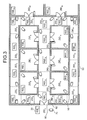
- FIG. 3 shows one example of arrangement of tag readers, lock mechanisms, and surveillance cameras
- FIG. 4 explains a relation between the arrangement of the tag readers and capable range of detecting the RFID tag
- FIG. 5. shows the contents of a tag identification information table
- FIG. 6 shows the contents of a reader table
- FIG. 7 shows the contents of a person table
- FIG. 8 shows the contents of an attribute table
- FIG. 9 shows the contents of a tag-person table
- FIG. 10 shows the contents of a camera table
- FIG. 11 shows the contents of a door table
- FIG. 12 shows the contents of a track table
- FIG. 13 is a flowchart that explains an enter prohibit process
- FIG. 14 is a flowchart that explains a process for detecting a person not carrying the RFID tag
- FIG. 15 is a diagram that explains how a person in a video is recognized
- FIG. 16 shows the contents of a person recognition table
- FIG. 17 shows one example of message indicating presence of a person not carrying the RFID tag
- FIG. 18 is a flowchart that explains a suspicious person detection process
- FIG. 19 shows one example of a track comparison string
- FIG. 20 shows one example of route indication display
- FIG. 21 schematically shows a configuration of the monitoring system according to another embodiment of the present invention.
- FIG. 22 is a table that is transmitted by a relay device to an abnormality processing unit.
- FIG. 23 is a flowchart that explains a process for detecting person not carrying the RFID tag.
- FIG. 1 schematically shows a configuration of the monitoring system according to one embodiment of the present invention.
- the monitoring system shown in FIG. 1 is comprised of at least one RFID tag 10 , a plurality of tag readers 20 , a relay device 40 , a central monitoring device 100 , a plurality of door lock mechanisms 62 , and a plurality of surveillance cameras 70 .
- FIG. 2 schematically shows a configuration of the RFID tag 10 .
- the RFID tag 10 is comprised of a tag identification information storage 11 , a transmitter 12 , a switch 13 , an antenna 14 , a receiver 15 , a warning generator 9 , and a power supply 19 .
- the tag identification information storage 11 stores tag identification information that is unique to the RFID tag 10 .
- the transmitter 12 generates and transmits a signal that includes the tag identification information.
- the receiver 15 receives, via the switch 13 and the antenna 14 , the signal transmitted by the tag reader 20 and analyzes the signal.
- the switch 13 switches between transmission and reception of the signal via the antenna 14 .
- the switch is comprised of, for example, a directional coupler.
- the warning generator 9 is comprised of a light emitter 16 , a speaker 17 , and a vibrator 18 .
- the light emitter 16 is, for example, a light emission diode (LED), and emits, for example, red, yellow, blue, or green light.
- the speaker 17 outputs an alarm or a warning sound.
- the vibrator 18 vibrates the RFID tag 10 and it is comprised of, for example, an eccentric rotor that is employed in the mobile phones.
- the RFID tag 10 transmits a signal to the tag reader 20 .
- the signal generated by the transmitter 12 is transmitted to the tag reader 20 via the switch 13 and the antenna 14 .
- the transmission of the signal is performed at a certain timing which will be described in detail later.
- a tag label which is unique, is affixed on a surface of each of the RFID tag 10 .
- the tag label includes optical-readable characters, a barcode or the like.
- One tag reader 20 is arranged in each of a plurality of the predetermined surveillance areas.
- the tag reader 20 receives a signal from the RFID tag 10 carried by a person entering into the surveillance area corresponding to the tag reader 20 , extracts the tag identification information from the signal, and transmits the tag identification information to the relay device 40 .
- the tag reader 20 receives an instruction signal, that is to be transmitted to a particular RFID tag 10 , from the relay device 40 .
- the instruction signal includes various instructions.
- the tag reader 20 appends tag identification information corresponding to the particular RFID tag 10 to the instruction signal and transmits the instruction signal to the particular RFID tag 10 as a radio frequency signal.
- Each tag reader 20 is assigned with a unique reader identification information.
- a lock mechanism 62 is provided for a door corresponding to each one of the surveillance area.
- the lock mechanism 62 locks or unlocks (in other words, opens or closes) the door according to a lock control signal received from the central monitoring device 100 .
- the lock mechanisms 62 are assigned with door identification information DID 1 , DID 2 , DID 3 , . . . , respectively.
- One surveillance camera 70 is arranged in each of the surveillance areas.
- the surveillance camera 70 records a video of the corresponding surveillance area.
- the surveillance camera 70 transmits the video to the central monitoring device 100 .
- a direction and zoom of the surveillance camera 70 can controlled according to a camera control signal generated by the central monitoring device 100 .
- the surveillance cameras 70 are assigned with camera identification information CID 1 , CID 2 , CID 3 , . . . , respectively.
- FIG. 3 shows one example of arrangement of the tag readers 20 , the lock mechanisms 62 , and the surveillance cameras 70 .
- the surveillance areas are assigned with place code ZID 1 , ZID 2 , ZID 3 , . . . . , respectively.
- One tag reader 20 and one surveillance camera 70 are arranged in each surveillance area.
- the tag readers 20 are assigned with reader identification information RID 1 , RID 2 , RID 3 , . . . , respectively.
- Sensitivity of receiving (hereinafter, “receiving sensitivity”) a signal from the RFID tag 10 of each tag reader 20 is adjusted so that the tag reader 20 detect only the RFID tag 10 in the surveillance area corresponding to that tag reader 20 .
- the tag reader 20 can detect the RFID tag 10 only in the corresponding the surveillance area.
- the area in which a tag reader can detect a RFID tag (hereinafter, “detection range”) is circular with the tag reader at its center.
- FIG. 4 explains a relation between the arrangement and the detection range of the tag readers 20 .
- a timing at which a signal is transmitted from the RFID tag 10 may be set according to the distance between the adjoining tag readers 20 . For example, if the distance between the tag readers 20 is relatively small, it is preferable to set the timing at a shorter interval time so as to increase the accuracy of detecting the RFID tag 10 .
- the timing may be set considering factors other than the distance between the tag readers 20 . For example, assuming, for example, that the persons caring the RFID tag 10 are going to walk in a building, the timing may is set as once in a few seconds. By setting an appropriate timing it becomes possible to decrease the power consumption of the RFID tag 10 compared to the case in which the RFID tag 10 transmits the signals more number of times than necessary.
- the walls 50 are built so as to enclose some surveillance areas.
- the walls 50 separate individual surveillance areas. These walls 50 prevent, to some extent, detection of one RFID tag 10 simultaneously by a plurality of the tag readers 20 . That is, the walls 50 serve to decrease the work load of the tag reader 20 .
- the walls 50 are comprised of a material or have a thickness that makes it possible to interrupt passage of the radio frequency signals transmitted from the RFID tag 10 . It is needless to say that, as shown in FIG. 3, all of the surveillances areas needs not be enclosed with the walls 50 .
- the doors 60 are comprised of a material or have a thickness that makes it possible to interrupt passage of the radio frequency signals transmitted from the RFID tag 10 .
- the tag reader 20 is fixed on the wall above the door 60 , the door 60 can substantially interrupt the radio frequency signals even if it is not made of a specific material or does not have a specific thickness.
- the relay device 40 receives a signal, which includes the tag identification information, from the tag readers 20 arranged in a predetermined region.
- the relay device 40 appends reader information, which corresponding to the tag reader 20 that has received the signal from the RFID tag 10 , to the tag identification information, and sends the resultant signal to the central monitoring device 100 . If the tag readers 20 and the relay device 40 are connected to each other via separate cables, then the relay device 40 can identify from which tag reader 20 the resultant signal has been received based on from which cable the resultant signal has been received.
- each tag reader 20 appends own reader identification information to the tag identification information and transmits the resultant signal to the relay device 40 .
- the relay device 40 can identify the tag reader 20 based on the reader identification information included in the received signal.
- the relay device 40 also receives various instruction signals from the central monitoring device 100 , and transmits the instruction signals to the tag reader 20 or to the RFID tags 10 .
- the central monitoring device 100 is comprised of a data management unit 101 , an input device 110 , a tag label reader 112 , an abnormality processing unit 120 , a display 130 , a door controller 131 , a security unit 132 , a warning unit 133 , a camera controller 134 , a route indication unit 140 , a monitoring information storage 105 , a track pattern storage 160 , and a video storage 150 .
- the data management unit 101 receives a signal from the relay device 40 and extracts the tag identification information and the reader identification information from the received signal.
- the data management unit 101 sends the information extracted and the time of receipt of the signal to the monitoring information storage 105 .
- the monitoring information storage 105 stores the information and the time.
- the input device 110 is for inputting various data by an operator.
- the data includes, for example, data that is to be registered in the monitoring information storage 105 and instructions to the central monitoring device 100 .
- the input device 110 is, for example, a keyboard or a pointing device.
- the tag label reader 112 reads the tag label affixed to the RFID tag 10 .
- the abnormality processing unit 120 executes an entry prohibition process, a process for detecting person not carrying RFID tag, a suspicious person detection process, and route indication process. These processes are executed according to an instruction generated by the abnormality processing unit 120 at a predetermined time interval or according to an instruction input by the operator, referring to data stored in the monitoring information storage 105 , the track pattern storage 160 , and the video storage 150 . These processes will be described in detail later.
- the display 130 displays a video (hereinafter video will mean an image or a video or both), or a message according to an instruction (hereinafter, “abnormality instruction”) from the abnormality processing unit 120 .
- the video is stored in the video storage 150 .
- the message is based on, for example, the result of detection of entry into the surveillance area of a person who is not allowed to enter the surveillance area, a person not carrying the RFID tag, and a suspicious person.
- the display 130 is, for example, a cathode ray tube (CRT) display or a liquid crystal display (LCD).
- CTR cathode ray tube
- LCD liquid crystal display
- the door controller 131 controls the lock mechanism 62 specified by the door identification information.
- the security unit 132 transmits a message indicating instruction to the portable terminal carried by a guard.
- the warning unit 133 transmits a signal indicating a warning for the RFID tag 10 to the relay device 40 .
- the control of the lock mechanism 62 by the door controller 131 , the transmission of the message by the security unit 132 , and the transmission of the signal by the warning unit 133 are performed based on the abnormality instruction.
- the camera controller 134 controls the surveillance camera 70 specified by the camera identification information and makes the video storage 150 store the video based on the abnormality instruction or an instruction from the operator.
- the route indication unit 140 transmits a signal indicating a route guidance instruction for the RFID tag 10 to the relay device 40 based on the abnormality instruction.
- the monitoring information storage 105 stores a tag identification information table, a reader table, a person table, an. attribute table, a tag-person relation table, a camera table, a door table, and a track table. These tables contain data input by the operator via the input device 110 .
- the tag identification information table includes, as shown in FIG. 5, an association of the tag labels and the tag identification information. This tag identification information table is referred to determine tag identification information associated with the tag label that is read by the tag label reader 112 .
- the reader table includes, as shown in FIG. 6, an association of the reader identification information and place information.
- the place information includes place code, name, and zone of the place where the tag reader 20 specified by the reader identification information is arranged.
- the person table includes, as shown in FIG. 7, an association of person identification information and personal information.
- the person carrying the RFID tag 10 is identified from the person identification information.
- the personal information includes name, age, destination, and attribute information of the person that is specified by the person identification information.
- the attribute table includes, as shown in FIG. 8, an association of the place code, which is in the reader table, and the attribute information, which is in the person table.
- the attribute information includes attribute-1, attribute-2, and attribute-3.
- three attributes have been shown in the figure, there may be two attributes or even more than three attributes. These attributes specify whether the person is, for example, a guest, a general staff, a superior staff, a security manager, or a part-timer.
- Each attribute is a value that indicates whether the person is allowed to enter into the surveillance area that is identified by the place code.
- a person with attribute-2 is allowed to enter into the surveillance areas with the place codes ZID 1 and ZID 2 , and prohibited to enter into the surveillance area with the place code ZID 3 .
- the attribute table includes an attribute for a temporary but frequent visitor.
- this attribute for the visitor is initialized with the value that indicates prohibition of entry to all place codes, and then, the attribute is automatically changed to a value that indicates permission to entry into sections based on destination of the visitor in the person table of the visitor.
- the central monitoring device 100 has an attribute setting section. This attribute setting section creates the attribute table so that the surveillance areas, which are present on the best route between the entry and the destination, are set as the prohibited area for the visitor. The best route is the route that avoids majority of the prohibited areas for the visitor.
- the tag-person relation table includes, as shown in FIG. 9, an association of the tag identification information and the person identification information, which is in the person table. Especially, this tag-person relation table is useful to acquire the person identification information. Next, based on the person identification information, personal information of the person carrying the RFID tag 10 can be acquired by referring to the person table (see FIG. 7).
- the camera table includes, as shown in FIG. 10, an association of the camera identification information and the place code of the reader table.
- the door table includes, as shown in FIG. 11, an association of the door identification information with the place code of the reader table.
- the tag identification information table, the reader table, the person table, the attribute table, the tag-person relation table, the camera table, and the door table are mutually in the normalized relation, and construct the relational database.
- the attribute table, the camera table, and the door table are associated with the place code, because, there is less probability that the place code is changed.
- the reader identification information of the tag reader 20 that has broken down is merely changed in the reader table. In this way, it becomes possible to reduce the work load, for changing the information, on the manager of the system.
- the track table is managed by the data management unit 101 .
- the track table includes, as shown in FIG. 12, an association of the place code with time information in the tag identification information.
- the time information includes entry time (t 0 ), exit time (t 1 ), and stay period, in seconds, with respect to the surveillance area that is specified by the place code.
- the video storage 150 stores video and layout images.
- the video is acquired from the surveillance cameras 70 via the camera controller 134 .
- the layout images show the plan view of the surveillance areas and the arrangements of the tag readers 20 and the like as shown in FIG. 3. It is preferable that the video and the layout images are encoded and compressed. Especially, it is desirable that the video is encoded in such a manner of encoding an individual object, for example, MPEG-4 (Moving Picture Coding Experts Group Phase 4). As a result, it becomes easy to take out the object such as the background image and the person from the video. Thus, it is possible to reduce, in the abnormality processing unit 120 , the load of processing such as extraction of the person from the image and detection of person's movements.
- the surveillance camera 70 may be configured to execute such encoding and compression.
- the track pattern storage 160 stores a track pattern that represents a suspicious action, in the form of numerical values or a character string according to a predetermined rule. This track pattern is referred to in the suspicious person detection process that is described in detail later.
- the central monitoring device 100 is an information processor such as a personal computer or a work station.
- the central monitoring device 100 is comprised of a main processing unit (MPU), a secondary storage such as a memory and a hard disk drive (HDD), output devices such as a display unit and/or a printer, and input devices such as a keyboard and/or a mouse.
- the central monitoring device 100 may further serve the same function as the tag reader 20 and read the tag identification information of the RFID tag 10 thereby.
- FIG. 13 is a flowchart of entry determination process. It is assumed here that the tag readers 20 are connected to the relay device 40 through a single common cable.
- the RFID tag 10 which is carried by a person, periodically transmits own tag identification information.
- the tag reader 20 in that surveillance area receives the tag identification information of the RFID tag 10 carried by that person (step S 11 ).
- the tag reader 20 can detect and identify the RFID tags 10 existing in the surveillance area.
- the tag reader 20 appends own reader identification information to the tag identification information and transmits the resultant signal to the relay device 40 (step S 21 ).
- the relay device 40 receives the signal, that is the tag identification information and the reader identification information, and transmits the set of information to the data management unit 101 of the central monitoring device 100 (step S 31 ).
- the data management unit 101 executes a track table registration process based on the received tag identification information and the reader identification information (step S 41 ).
- the track table registration process concretely, first, the data management unit 101 , by referring to the monitoring information storage 105 , confirms whether the track table of the tag identification information received has been created. If it is determined that the track table has not been created, the monitoring information storage 105 creates a track table of the corresponding tag identification information. Then, the data management unit 101 refers to the reader table (see FIG. 6) and determines the place code corresponding to the reader identification information received. Further, the data management unit 101 registers this place code in the place code field of the track table (see FIG. 12) (hereinafter, “first registration process”).
- the data management unit 101 registers the time (hereinafter, “reception time”) at which the tag identification information and the reader identification information were received as the entry time (hereinafter, “second registration process”). On the other hand, if an entry time has been recorded corresponding to this place code, then the data management unit 101 registers the reception time as an exit time (hereinafter, “third registration process”). The data management unit 101 repeats the third registration process until the place code has changed. When the place code has changed, the data management unit 101 executes the first registration process with respect to the changed place code. Once the entry time and the exit time are registered in the track table, the data management unit 101 calculates the stay period from the entry time and the exit time, and registers the stay period in the track table.
- the track table is updated at the timing that the data management unit 101 receives the tag identification information and the reader identification information from the relay device 40 . It is assumed here that each tag reader 20 is given the priority of detecting the RFID tag 10 .
- the place code is a record of movements of each of the RFID tags 10 . Since the place code is the primary key in the track table for each tag identification information, even if the reader identification information has been changed due to the failure of the tag reader 20 , it is possible continuously to refer to past movement history of the RFID tag 10 .
- the abnormality processing unit 120 executes the entry determination process periodically or when the track table is updated.
- the abnormality processing unit 120 refers to the tag-person relation table (see FIG. 9) and determines the person identification information based on the tag identification information, refers to the person table (see FIG. 7) and determines the attribute information based on the person identification information, refers to the attribute table (see FIG. 8) and obtains information about whether the person is allowed or prohibited to enter (hereinafter, “information of the permission or prohibition”) based on the attribute information (step S 42 in FIG. 13). Furthermore, the abnormality processing unit 120 acquires the place code registered at the first registration process from the information of the permission or prohibition. If the value acquired indicates the prohibition of the entry, the abnormality processing unit 120 judges that the person carrying the RFID tag 10 of the tag identification information received at the first registration process is not allowed to enter into the surveillance area specified at the, first registration process (step S 43 ).
- the abnormality processing unit 120 when judging the prohibition of the entry, specifies the tag identification information and the reader identification information from the track table and the reader table. Then, the abnormality processing unit 120 transmits a first warning signal to the warning unit 133 .
- the warning signal includes the tag identification information, the reader identification information, and a warning instruction.
- the warning unit 133 transmits this first warning signal to the relay device 40 (step S 44 ).
- the relay device 40 extracts the tag identification information, the reader identification information, and the warning instruction from this first warning signal, and transmits a second warning signal to the tag reader 20 specified by this reader identification information (step S 32 ).
- the second warning signal includes the tag identification information and the warning instruction.
- the tag reader 20 extracts the tag identification information and the warning instruction from the second warning signal and transmits a third warning signal to the RFID tag 10 specified by this tag identification information (step S 22 ).
- the third warning signal includes the tag identification information and the warning instruction.
- the RFID tag 10 extracts the warning instruction from the third warning signal and activates the warning generator 9 (see FIG. 2) according to the warning instruction (step S 12 ).
- the warning generator 9 controls any one or more of the light emitter 16 , the speaker 17 , and the vibrator 18 so as to emit light, output an alarm, or vibrate the RFID tag 10 .
- the person carrying the RFID tag 10 comes to know that he has entered into an area in which he is not suppose to enter.
- the speaker 17 may be configured to gradually increase the volume of the alarm. In that case, at the initial stage, when the volume is low, only the person carrying the RFID tag 10 will hear the warning and take appropriate measures. However, if the person does not take appropriate measures, then the volume will become louder and louder and persons around this person, for example, a guard, will come to know that somebody is entering into an area in which he is not supposed to. This makes it possible to inform an entry of a person into the prohibited area to persons around that person and determine the person as a suspicious person.
- the abnormality processing unit 120 confirms, by referring to the reader table and the door table, whether the surveillance area into which the person has entered and the surveillance areas near that surveillance areas have the lock mechanism 62 (step S 45 ). If these surveillance areas have the lock mechanism 62 , the abnormality processing unit 120 further confirms, by referring to the attribute table, whether the lock mechanism 62 is located in the prohibited area for the tag identification information received at the step S 31 . If the lock mechanism 62 is located, the abnormality processing unit 120 transmits a door control signal to the door controller 131 (step S 46 ).
- the door control signal includes the door identification information specifying the lock mechanism 62 located in the prohibited area and a lock instruction.
- the lock mechanism 62 when receiving the lock instruction from the door controller 31 , locks the corresponding door. As a result, it is possible to prevent the person from entering into the surveillance area via the door. If the door is locked in this way, it is unlocked when the person goes away from the prohibited area.
- the abnormality processing unit 120 by referring to the track table, outputs an unlock instruction with respect to the lock mechanism 62 via the door controller 131 so that the locked door returns to an unlocked state.
- the abnormality processing unit 120 specifies the camera identification information by referring to the reader table and the camera table (step S 47 ). Then, the abnormality processing unit 120 transmits a camera control signal to the camera controller 134 (step S 48 ).
- the camera control signal includes the camera identification information specified and a camera control instruction.
- the camera control instruction indicates operation, for example, start-up and zooming, of the surveillance camera 70 specified by the camera identification information.
- the abnormality processing unit 120 may allow the display 130 to display the image taken by the surveillance camera 70 in real time.
- the abnormality processing unit 120 may cross-refer to the movements history of the RFID tag 10 in the track table and the video of the surveillance camera 70 in the video storage 150 , and make the display 130 display the images of the past behavior of the suspicious person.
- the abnormality processing unit 120 by referring to the track table and the camera table, may switch the surveillance camera in the surveillance area where the RFID tag 10 is detected to a main camera. This makes it possible to track the person decided as suspicious.
- the abnormality processing unit 120 allows the display 130 to display the message or image indicating that a person has been detected in the prohibited area (step S 49 ).
- the abnormality processing unit 120 may make the display 130 display other information such as the surveillance area information, the person information, and the tag identification information.
- the abnormality processing unit 120 may be configured to transmit a guard signal to the security unit 132 .
- This guard signal includes the surveillance area information, the personal information, the tag identification information and the like.
- the abnormality processing unit 120 may be configured to transmit the guard signal only when the stay period in the prohibited area exceeds the predetermined time.
- the warning processes of the abnormality processing unit 120 as described above may be combined or one of them may be selected depending on situations.
- the attribute information is managed by the central monitoring device 100 , if necessary, for example, it is easy to change the attribute information depending on the situation. For example, the attribute information may be changed based on a number of times the person is to be warned.
- the monitoring system judges whether to execute the warning process depending on the current position of the RFID tag 10 . Therefore, the warning processes may be registered as the history of usage of the RFID tag 10 in the track table. As a result, it becomes easy to identify the person who has been warned again and again (that is, the suspicious person).
- the abnormality processing unit 120 makes the display 130 display the plan view, which is stored in the video storage 150 (same as the one shown in FIG. 3), of the surveillance area. Further in this case, the abnormality processing unit 120 , by referring to the various tables mentioned above, makes the display 130 display in the plan view an arrangement of the tag readers 20 . Then, for example, the mark indicating the arrangement of the RFID tag 10 , for which the warning process has been repeated for more than a predetermined times (for example, three times), is displayed with a special display mode, for example, displayed with a different color or made to blink.
- a predetermined times for example, three times
- the abnormality processing unit 120 may transmit the camera control signal to the camera controller 134 and make the camera take a video of particularly the surveillance area where this RFID tag 10 is located.
- the abnormality processing unit 120 may be configured to execute the warning process based on the track pattern stored in the track pattern storage 160 .
- the attribute in the attribute table indicates either the permission or prohibition of the entry, however, the attribute may indicate any other status such as null.
- the abnormality processing unit 120 may be configured to determine one tag reader as the tag reader that has detected the RFID tag (hereinafter, “effective tag reader”) based on the permission or prohibition of the entry stored in the attribute table. That is, which tag reader is to be made an effective tag reader is determined based on the attribute of the person entering the surveillance area.
- the surveillance area to be a target (hereinafter, “target area”) is specified (step S 101 ).
- the operator specifies the area by using the input device 110 .
- the abnormality processing unit 120 by referring to the reader table, periodically specifies the surveillance areas one by one.
- the abnormality processing unit 120 extracts the tack table from the monitoring information storage 105 .
- the track table includes both the place code of the target area and the record which does not register the exit time, but register the entry time.
- the abnormality processing unit 120 specifies the tag identification information corresponding to the track table extracted.
- the abnormality processing unit 120 calculates the number TN of the RFID tags 10 in the target area (step S 102 ).
- the abnormality processing unit 120 determines the camera identification information from the camera table for the place code of the target area, and acquires the latest video from the video storage 150 based on the camera identification information (step S 103 ). Next, the abnormality processing unit 120 calculates the number CN of the persons present in the video (step S 104 ).
- the abnormality processing unit 120 judges whether TN is equal to CN (step S 105 ). In other words, the abnormality processing unit 120 judges whether the number of RFID tags is same as the number of persons in the area. If not, the abnormality processing unit 120 judges whether CN is greater than TN. If the value of CN is greater than that of TN, for example, by one, it means that there is one person in the video who is not carrying the RFID tag 10 , and in this case the abnormality processing unit 120 makes the display 130 display a message indicating presence of a person not carrying the RFID tag 10 (step S 106 ). If it is decided in the step S 105 that the values of CN and TN are equal, then the abnormality processing unit 120 either does nothing or makes the display 130 display values of CN and TN.
- the abnormality processing unit 120 in addition to calculating CN, may be configured to identify, by referring to the track table, the person who does not carry the RFID tag 10 .
- person objects in the image 91 are detected and characterized by diagnostic features such as height, color, and clothes.
- identification number is assigned to each of the person objects and recorded in a predetermined table 93 .
- the abnormality processing unit 120 specifies, the person object recognized with a combination of the same diagnostic feature between different images, by the identification number.
- the abnormality processing unit 120 creates a person recognition table shown in FIG. 16.
- the person recognition table indicates an association of the identification number with the time of the recognition and the place code of the target area.
- the abnormality processing unit 120 extracts, the movements history of the RFID tag 10 which has the combination of the same time as that of the person recognition table, from the track table.
- This movements history is, in detail, a tag movement history table that associates the tag identification information with the place code and time.
- the abnormality processing unit 120 compares this tag movements history table and the person recognition table, and excludes the record which has the same transition of the place code as that of the tag movements history table from the person recognition table. As a result, the abnormality processing unit 120 decides the person object specified by the remaining record as a person not carrying the RFID tag 10 .
- the abnormality processing unit 120 may be configured to make, as shown in FIG. 17, the display 130 display the camera image 130 c and to highlight the person object 130 h corresponding to the person not carrying the RFID tag 10 .
- the abnormality processing unit 120 may be configured to cause, as shown in FIG. 17, the display 130 to display the value of TN calculated at the step S 102 (see FIG. 14), the value of CN calculated at the step S 104 (see FIG. 14), the tag identification information of the RFID tag 10 detected, and a message indicating presence of the person not carrying the RFID tag 10 .
- the display 130 may display the value of TN calculated at the step S 102 (see FIG. 14), the value of CN calculated at the step S 104 (see FIG. 14), the tag identification information of the RFID tag 10 detected, and a message indicating presence of the person not carrying the RFID tag 10 .
- the display 130 may display the value of TN calculated at the step S 102 (see FIG. 14), the value of CN calculated at the step S 104 (see FIG. 14), the tag identification information of the RFID tag 10 detected, and a message indicating presence of the person not carrying the RFID tag 10 .
- the value of CN is “2”
- the value of TN is “1
- the suspicious person detection process will be explained now in detail with reference to FIG. 18. This suspicious person detection process is executed by the central monitoring device 100 .
- an operator inputs, by using the input device 110 , a place in which a suspicious person to be detected (step S 201 ), a range of time during which the suspicious person is to be detected (step S 202 ), and a condition to detect the suspicious person (step S 203 ).
- a place in which a suspicious person to be detected step S 201
- a range of time during which the suspicious person is to be detected step S 202
- a condition to detect the suspicious person step S 203 .
- two or more surveillance areas may be input as the place.
- the condition is, for example, whether 100 persons have been identified in the place that is input at the step S 201 , or whether there is a person having specific personal information.
- the abnormality processing unit 120 judges whether movements history of the RFID tag 10 which meets the data for detection has been recorded in the track table (step S 204 ).
- the data for detection is the place, the range of time, and the condition that are input at the steps S 201 to S 203 respectively. If it is decided that the data has been recorded, the abnormality processing unit 120 acquires the movements history which meets the data for detection and generates a track comparison string from the data acquired (step S 205 ).
- FIG. 19 shows one example of the track comparison string.
- the track comparison string is comprised of a character string that indicates the place code and the stay period with respect to each tag identification information corresponding to the data acquired at the step S 205 .
- one character in the track comparison string indicates that the RFID tag 10 specified by the tag identification information has stayed for one minute in the surveillance area corresponding to the place code which the one character represents.
- the place codes ZID 1 , ZID 2 , and ZID 3 are represented by A, B, and C respectively. Therefore, the track comparison string shown in FIG.
- the abnormality processing unit 120 compares the track comparison string with each track pattern stored in the track pattern storage 160 (step S 206 ). Examples of the track pattern are described as follows.
- Track pattern 1 The RFID tag 10 has stayed in the same surveillance area for a longer time than a predetermined time. This pattern is in order to detect a person who stays in one area for a longer time than necessary. In other words, this track pattern may be used to detect an RFID tag 10 that is thrown away by the person carrying it or that has been fallen from the hands of the person carrying it.
- Track pattern 2 The RFID tag 10 has shuttled between two surveillance areas for a number of times greater than a predetermined number, within a predetermined time. In other words, this pattern may be used to detect a person who is wandering or who has got lost.
- Track pattern 3 The RFID tag 10 has shuttled between a predetermined number of the surveillance areas for a number of times greater than a predetermined number, within a predetermined time. In other words, this pattern may be used to detect a person who is moving faster than necessary.
- the above track patterns may also be represented by a combination of a code “*”, which indicates a character or a character string, and a place code.
- the above track pattern 1 may be represented as, when the predetermined time is one hour, PAT1 as follows:
- PAT 1 AAA . . . A (a series of 60 characters “ A ”)
- the above track pattern 2 may be represented as, when the predetermined time is 30 minutes and the predetermined number is three, PAT2 as follows:
- the abnormality processing unit 120 verifies whether the track comparison string includes such a track pattern. For example, consider that a track comparison string for some person is
- This track comparison string does not match with the PAT1, however, matches with the PAT2. In other words, the person has shuttled between areas A and B at least for three times within 30 minutes.
- the track pattern storage 160 may be configured to store track patterns other that the ones mentioned above.
- a track pattern that detects whether there is the RFID tag 10 which is out of the surveillance area may be stored in the track pattern storage 160 .
- a track pattern that detects whether there is the RFID tag 10 which has been destroyed by intention or which is not functioning properly may be stored in the track pattern storage 160 .
- the abnormality processing unit 120 determines whether real track pattern matches with the track comparison string stored in the track pattern storage 160 . If it is decided that the real track pattern matches with the track comparison string (step S 207 , Yes), the abnormality processing unit 120 , generates, by referring to the track table, movement history (i.e., track) of the RFID tag 10 behaving as the track comparison string, and causes the display 130 to display the track generated (step S 208 ). Furthermore, the abnormality processing unit 120 determines, by referring to the various tables explained above, the tag identification information, the surveillance area corresponding to the current position of the RFID tag 10 , and the personal information (step S 209 ). Then, the abnormality processing unit 120 causes the display 130 to display these information (step S 210 ).
- the abnormality processing unit 120 may be configured not only to compare the track comparison string and the track pattern but to verify a correlation between two track comparison strings. Concretely, the abnormality processing unit 120 calculates, by comparing similarities used in the genome field, the similarity between two track comparison strings. As a result, when the similarity is greater than a predetermined degree, the person behaving as the track comparison string is decided as suspicious.
- the suspicious person may be decided not only by the track but by a track pattern that is defined based on the personal information.
- the abnormality processing unit 120 may be configured to, by referring to the personal information of the person table, judge whether the person is the guard or on the blacklist (e.g., malfeasant list).
- the route indication process is executed by the route indication unit 140 of the central monitoring device 100 .
- the RFID tag 10 in order to receive a routing instruction from this route indication unit 140 , must be provided with functions same as a PC card.
- the PC card 170 is composed of a wireless transmitting/receiving unit 171 and the antenna 14 .
- the wireless transmitting/receiving unit 171 includes the tag identification storage 11 , the transmitter 12 , the switch 13 , and the receiver 15 shown in FIG. 2.
- This PC card 170 is inserted into a portable information terminal 180 such as the personal digital assistant.
- the warning generator 9 shown in FIG. 2 is installed in the portable information terminal 180 . That is, a display, a speaker, and a vibrator of the portable information terminal 180 correspond to the light emitter 16 , the speaker 17 , and the vibrator 18 respectively.
- the route indication unit 140 acquires video from the video storage 150 . Moreover, the route indication unit 140 extracts, from the monitoring information storage 105 , information of the prohibited area and position information of the portable information terminal 180 that functions as the RFID tag 10 . The route indication unit 140 transmits the information acquired to the portable information terminal 180 via the relay device 40 .
- the portable information terminal 180 receives the information through the antenna 14 and the wireless transmitting/receiving unit 171 . As a result, the portable information terminal 180 causes, as shown in FIG. 20, the display 169 to display the image that indicates a map 161 of the surveillance areas, a route line 162 , prohibited area marks 163 , a current position mark 164 , and a direction mark 165 .
- the portable information terminal 180 must include, to display the direction mark 165 , a direction detecting unit such as a gyroscope and a geomagnetic direction sensor.
- the portable information terminal 180 must also have a function of generating an image for the direction mark 165 that turns according to the output of the direction detecting unit.
- the portable information terminal 180 may be configured to cause the display 169 to change color of the marks depending on the situation.
- the direction mark 165 may be displayed in green (or blue) when the person carrying the portable information terminal 180 moves along a proper route or moves toward a proper destination or towards an exit.
- the direction mark 165 may be displayed in red when the person moves towards a prohibited area or displayed in yellow in other cases. If the direction mark 165 is displayed in this manner, the person can easily know whether he is following a proper route. Since such a display is possible with simple and low cost light emission diodes the costly PDA is not necessarily required.
- FIG. 21 schematically shows a configuration of the monitoring system according to another embodiment of the present invention.
- the components that perform same or similar functions or have same or similar configurations as those shown in FIG. 1 have been denoted with the same reference numerals and their explanation is omitted to avoid simple repetition of explanation.
- the monitoring system shown in FIG. 21 is different from the system shown in FIG. 1 in that the relay device 240 is provided in place of the relay device 40 , moreover, a plurality of human sensors 30 are provided.
- One human sensor 30 is arranged in each the surveillance area in the same manner as the tag reader 20 .
- the human sensor 30 detects presence of a person in the corresponding surveillance area.
- the human sensor 30 may perform the detection based on infrared light, voice, weight, or electric waves of a portable device (e.g., a mobile phone) carried by the person.
- This embodiment is characterized by detecting a person not carrying the RFID tag 10 by using the human sensor 30 .
- the relay device 240 has the same functions as the relay device 40 shown in FIG. 1, and in addition to it, collects the result of detection by the human sensors 30 .
- the relay device 240 transmits detection information to the abnormality processing unit 120 at a predetermined interval.
- This detection information includes a correlation of the reader identification information, the tag identification information, and result of detection by the human sensor 30 for each surveillance area, as shown in FIG. 22. For example, “0” in sensor output (that is, the output of the human sensor 30 ) means that the human sensor 30 did not detect a person and “1” means that the human sensor 30 detect a person.
- FIG. 23 is a flowchart that explains a process for detecting person not carrying the RFID tag 10 .
- the abnormality processing unit 120 receives the information in the correlation table shown in FIG. 22 from the relay device 240 (step S 301 ), and verifies whether the output of the human sensor 30 of the correlation table indicates “1” (step S 302 ). If the output indicates “1”, that is, if there is at least one person in the surveillance area, the abnormality processing unit 120 calculates the number of the tag identification information from the correlation table, and thereby acquires the number TN of the RFID tags 10 that have been detected in the surveillance area (step S 303 ).
- step S 304 If the value of TN is zero (step S 304 , Yes), the abnormality processing unit 120 causes the display 130 to display a message that indicates presence of a person not carrying the RFID tag 10 in the surveillance area (step S 305 ). On the other hand, when the value of TN is not zero (step S 304 , no) or when the output of the human sensor 30 is not “1” (step S 302 , no), then the entry determination process is executed (step S 306 ). Concretely, the abnormality processing unit 120 executes the steps S 42 to S 49 , the relay device 240 executes the step S 32 , the tag reader 20 executes the step S 22 , and the RFID tag 10 executes the step S 12 .
- the abnormality processing unit 120 can control the entry of the person into the surveillance area based on information about the entry of the permission or prohibition that is recorded in the attribute table, and current position and movements history of the RFID tag 10 that are recorded in the track table.
- the method guarantees a precise control on the entry of a person into the surveillance area.
- the abnormality processing unit 120 recognizes the attribute information of the person, by means of analyzing the track of the person from the position history of the RFID tag 10 that is recorded in the track table. As a result, it is possible to detect the suspicious person based on the attribute information.
- the route indication unit 140 transmits the data stored in the monitoring information storage 105 and the video storage 150 , to the portable information terminal 180 that functions as the RFID tag 10 . As a result, by using the data, it is possible to navigate the person entering the surveillance area.
- the method according to the present invention may be executed as a computer program.
- a program that executes the entry determination process, the process for detecting person not carrying the RFID tag, the suspicious person detection process, and the route indication process may be recorded on a computer-readable recording medium.
- the recording medium there may be used an optical disk, a flexible disk, a hard disk, etc.
Abstract
Description
- This application is based upon and claims the benefit of priority from the prior Japanese Patent Applications No. 2002-086782 filed on Mar. 26, 2002 and No. 2002-092485 filed on Mar. 28, 2002; the entire contents of which are incorporated herein by reference.
- 1) Field of the Invention
- The present invention relates to a monitoring method of detecting, for example, entry of a person into a prohibited area, which is a part of a relatively closed area, such as a building or an airport, based on the person's personal information or behavior (hereinafter, “movement”).
- 2) Description of the Related Art
- Conventionally a visual monitoring system is known in which a surveillance camera, the direction and the zoom of which can be remotely controlled as desired, is arranged in a specified area. Persons entering into the specified area are monitored visually from a remote place based on the images or video taken by the camera.
- In this visual monitoring system, a judgment whether the person monitored by the surveillance camera is suspicious or not, is made based upon visual observation. However, the judgment becomes difficult when a lot of cameras are set because the area to be monitored is big, or the number of persons to be monitored is large.
- Moreover, a wide area monitoring system has been disclosed in Japanese Patent Application Laid-Open No. 9-130781. In this wide area monitoring system, a person is identified at an entrance of, for example, a building, based on a wireless card carried by that person, and a person decided as suspicious is tracked with a surveillance camera.
- In this wide area monitoring system also the suspicious person is tracked using the video taken by the surveillance camera. However, the tracking becomes difficult when there are a lot of persons around the suspicious person.
- Furthermore, a monitoring system has been disclosed in Japanese Patent Application Laid-Open No. 8-163652. In this monitoring system, a portable terminal is handed over to a person entering into, for example, a building. This portable terminal is capable of determining its own position and transmitting a signal that indicates the position. In addition, a surveillance camera monitors an area of the building that is prohibited. Whether a person has entered the prohibited area is decided based on the signal from the portable terminal carried by that person, and the entry of the person into the prohibited area is re-confirmed through the images or the video taken by the surveillance camera. The portable terminal operates based on, for instance, the Global Positioning Satellite (GPS) system or the Personal Handyphone System (PHS).
- In this monitoring system, position of the portable terminal is determined using the GPS or the PHS. However, the resolution of position measurement using the GPS or the PHS is low in view of the fact that the object of monitoring are, rooms or halls in a building, small. Therefore, the precision of the monitoring is low.
- Moreover, a card monitoring system and a password monitoring system are know in which a person inserts a magnetic card or enters a password in a device provided at the entrance of, for example, a building. The person is allowed to enter into the building only if the magnetic card or password is authentic. In these card monitoring system and password monitoring system, there is a door, which is generally locked, at the entrance of the area and the area is enclosed with walls from all the sides. The door is opened only when the person has an authentic magnetic card or an authentic password. Thus, anyone without an authentic magnetic card or a password can not enter the area.
- Furthermore, a transponder card monitoring system has been disclosed in Japanese Patent No. 2605014. In this transponder card monitoring system, a person entering into, for example, a building, carries a transponder card that outputs a signal, and a device that receives the signal is arranged near the entrance of the building. This device receives the signal form the transponder card carried by the persons entering into the building and decides whether a person is to be allowed to enter the building based on the signal.
- In the card monitoring system, the password monitoring system, and the transponder card monitoring system, whether the person is allowed to enter is decided at the entrance. However, the person is not monitored once he passes through the entrance. Furthermore, the prohibited area needs to be enclosed with walls from all sides, and a lot of doors with lock mechanism are required to allow different entry permission depending on the person. Therefore, in these systems, since the walls and the locks, the magnetic cards or the transponder cards or the devices for entering passwords are required, there is a problem that the system becomes costly. Moreover, the person can not be monitored once he passes through the door. In addition, a person may pass through the door that was opened for some reason, say for some other person. Furthermore, since checking whether the cards or the passwords are authentic and opening the door when the cards or the passwords are authentic requires time and people have to wait till the door opens even if they are authorized to enter.
- Moreover, a radio terminal alarm system has been disclosed in Japanese Patent No. 2901586. In this radio terminal alarm system, a radio terminal carried by a person receives a radio signal from a radio station. The radio signal indicates whether the radio terminal, that is, the person carrying the radio terminal, is allowed to enter in an area where it is trying to enter. If the person is trying to enter into a prohibited area, the radio station sends a signal to the radio terminal so as to output an alarm. Thus, a person carrying the radio terminal comes to know that the area is the prohibited area. In addition, when persons around the person hear the alarm, they come to know that the person is not allowed to enter the prohibited area and thus the alarm serves as a warning to the surrounding persons.
- In this radio terminal alarm system, an alarm is generated when a person tries to enter the prohibited area. However, it is easy to stop the alarm and enter the prohibited area. Furthermore, it is impossible to flexibly change authority for entry into the prohibited area based on entry history and to control the authority of the person who has acted illegally in the past. Moreover, there is a problem that the warning is not correctly done if the radio terminal is damaged intentionally or non-intentionally or thrown away.
- Moreover, in all the conventional systems described above, it can not be decided whether a person is a suspicious person and then automatically control a surveillance camera so as to monitor the suspicious person or to decide whether a person has entered an area in which he is not supposed to and show him a route which he should follow.
- A system is know that employs a radio frequency identification (hereinafter, “RFID”) tag to monitor movements of a person. However, there is no prior art that employs the RFID tag to a security system.
- It is an object of the present invention to provide a method and a computer program product capable of easily monitoring movement of a person.
- The monitoring method according to embodiments of the present invention comprises acquiring tag identification information that is unique to a radio frequency identification tag carried by a person, and reader identification information that is unique to a tag reader capable of detecting the radio frequency identification tag in a predetermined area; acquiring attribute information that is information about the person carrying the radio frequency identification tag based on the tag identification information acquired; acquiring area information that is information about the predetermined area based on the reader identification information; and determining whether the person carrying the radio frequency identification tag is allowed to enter the predetermined area based on the attribute information and the area information.
- The monitoring method according to embodiments of the present invention comprises acquiring tag identification information that is unique to a radio frequency identification tag carried by a person, and reader identification information that is unique to a tag reader capable of detecting the radio frequency identification tag in a predetermined area; recording positional history that indicates a position of the radio frequency identification tag at a certain time based on timing at which the tag identification information and the reader identification information are acquired; recording a video of the predetermined area and time at which the video is recorded; calculating the number of tag identification information detected by a predetermined tag reader based on the positional history; calculating the number of persons in the predetermined area based on the video; and determining whether the number of the tag identification information is equal to the number of persons.
- The monitoring method according to embodiments of the present invention comprises acquiring tag identification information that is unique to a radio frequency identification tag carried by a person, and reader identification information that is unique to a tag reader capable of detecting the radio frequency identification tag in a predetermined area; recording positional history that indicates position of the radio frequency identification tag at a certain time based on timing at which the tag identification information and the reader identification information are acquired; detecting with a human detector whether a person is present in a predetermined area corresponding to a predetermined tag reader; acquiring the tag identification information detected by the predetermined tag reader based on the positional history; and determining whether the detection by the human detector and the tag identification information satisfy a predetermined relationship.
- The monitoring method according to embodiments of the present invention comprises acquiring tag identification information that is unique to a radio frequency identification tag carried by a person, and reader identification information that is unique to a tag reader capable of detecting the radio frequency identification tag in a predetermined area; recording positional history that indicates a position of the radio frequency identification tag at a certain time based on timing at which the tag identification information and the reader identification information are acquired; preparing a pattern of the positional history for each of the tag identification information based on the positional history; and determining whether at least a portion of the prepared pattern matches with any one of already recorded patterns.
- The computer program product according to embodiments of the present invention realizes the monitoring method according to embodiments of the present invention on a computer.
- FIG. 1 schematically shows a configuration of the monitoring system according to one embodiment of the present invention;
- FIG. 2 schematically shows a configuration of the RFID tag;
- FIG. 3 shows one example of arrangement of tag readers, lock mechanisms, and surveillance cameras;
- FIG. 4 explains a relation between the arrangement of the tag readers and capable range of detecting the RFID tag;
- FIG. 5.shows the contents of a tag identification information table;
- FIG. 6 shows the contents of a reader table;
- FIG. 7 shows the contents of a person table;
- FIG. 8 shows the contents of an attribute table;
- FIG. 9 shows the contents of a tag-person table;
- FIG. 10 shows the contents of a camera table;
- FIG. 11 shows the contents of a door table;
- FIG. 12 shows the contents of a track table;
- FIG. 13 is a flowchart that explains an enter prohibit process;
- FIG. 14 is a flowchart that explains a process for detecting a person not carrying the RFID tag;
- FIG. 15 is a diagram that explains how a person in a video is recognized;
- FIG. 16 shows the contents of a person recognition table;
- FIG. 17 shows one example of message indicating presence of a person not carrying the RFID tag;
- FIG. 18 is a flowchart that explains a suspicious person detection process;
- FIG. 19 shows one example of a track comparison string;
- FIG. 20 shows one example of route indication display;
- FIG. 21 schematically shows a configuration of the monitoring system according to another embodiment of the present invention;
- FIG. 22 is a table that is transmitted by a relay device to an abnormality processing unit; and
- FIG. 23 is a flowchart that explains a process for detecting person not carrying the RFID tag.
- Exemplary embodiments of the method and the computer program product relating to the present invention will be explained in detail below with reference to the accompanying drawings.
- FIG. 1 schematically shows a configuration of the monitoring system according to one embodiment of the present invention. The monitoring system shown in FIG. 1 is comprised of at least one
RFID tag 10, a plurality oftag readers 20, arelay device 40, acentral monitoring device 100, a plurality ofdoor lock mechanisms 62, and a plurality ofsurveillance cameras 70. - One
RFID tag 10 is carried by a person who enters a predetermined surveillance area. FIG. 2 schematically shows a configuration of theRFID tag 10. TheRFID tag 10 is comprised of a tagidentification information storage 11, atransmitter 12, aswitch 13, anantenna 14, areceiver 15, awarning generator 9, and apower supply 19. The tagidentification information storage 11 stores tag identification information that is unique to theRFID tag 10. Thetransmitter 12 generates and transmits a signal that includes the tag identification information. Thereceiver 15 receives, via theswitch 13 and theantenna 14, the signal transmitted by thetag reader 20 and analyzes the signal. Theswitch 13 switches between transmission and reception of the signal via theantenna 14. The switch is comprised of, for example, a directional coupler. - The
warning generator 9 is comprised of alight emitter 16, aspeaker 17, and avibrator 18. Thelight emitter 16 is, for example, a light emission diode (LED), and emits, for example, red, yellow, blue, or green light. Thespeaker 17 outputs an alarm or a warning sound. Thevibrator 18 vibrates theRFID tag 10 and it is comprised of, for example, an eccentric rotor that is employed in the mobile phones. - The
RFID tag 10 transmits a signal to thetag reader 20. Precisely, the signal generated by thetransmitter 12 is transmitted to thetag reader 20 via theswitch 13 and theantenna 14. The transmission of the signal is performed at a certain timing which will be described in detail later. A tag label, which is unique, is affixed on a surface of each of theRFID tag 10. The tag label includes optical-readable characters, a barcode or the like. - One
tag reader 20 is arranged in each of a plurality of the predetermined surveillance areas. Thetag reader 20 receives a signal from theRFID tag 10 carried by a person entering into the surveillance area corresponding to thetag reader 20, extracts the tag identification information from the signal, and transmits the tag identification information to therelay device 40. - Moreover, the
tag reader 20 receives an instruction signal, that is to be transmitted to aparticular RFID tag 10, from therelay device 40. The instruction signal includes various instructions. Thetag reader 20 appends tag identification information corresponding to theparticular RFID tag 10 to the instruction signal and transmits the instruction signal to theparticular RFID tag 10 as a radio frequency signal. Eachtag reader 20 is assigned with a unique reader identification information. - A
lock mechanism 62 is provided for a door corresponding to each one of the surveillance area. Thelock mechanism 62 locks or unlocks (in other words, opens or closes) the door according to a lock control signal received from thecentral monitoring device 100. Thelock mechanisms 62 are assigned with door identification information DID1, DID2, DID3, . . . , respectively. - One
surveillance camera 70 is arranged in each of the surveillance areas. Thesurveillance camera 70 records a video of the corresponding surveillance area. Thesurveillance camera 70 transmits the video to thecentral monitoring device 100. A direction and zoom of thesurveillance camera 70 can controlled according to a camera control signal generated by thecentral monitoring device 100. Further, thesurveillance cameras 70 are assigned with camera identification information CID1, CID2, CID3, . . . , respectively. - FIG. 3 shows one example of arrangement of the
tag readers 20, thelock mechanisms 62, and thesurveillance cameras 70. The surveillance areas are assigned with place code ZID1, ZID2, ZID3, . . . . , respectively. Onetag reader 20 and onesurveillance camera 70 are arranged in each surveillance area. Thetag readers 20 are assigned with reader identification information RID1, RID2, RID3, . . . , respectively. - Sensitivity of receiving (hereinafter, “receiving sensitivity”) a signal from the
RFID tag 10 of eachtag reader 20 is adjusted so that thetag reader 20 detect only theRFID tag 10 in the surveillance area corresponding to thattag reader 20. In other words, thetag reader 20 can detect theRFID tag 10 only in the corresponding the surveillance area. However, the area in which a tag reader can detect a RFID tag (hereinafter, “detection range”) is circular with the tag reader at its center. - FIG. 4 explains a relation between the arrangement and the detection range of the
tag readers 20. As shown in FIG. 4, it is desirable to adjust the receiving sensitivity and the position of each of thetag readers 20 in such a manner that detection ranges 21 of adjoiningtag readers 20 overlap with each other so that there is no area that is not covered by any of thetag readers 20. Because of such overlap, it may happen that oneRFID tag 10 is simultaneously read by a plurality oftag readers 20. However, in that case, therelay device 40 may be configured to give a priority to aspecific tag reader 20 based on certain conditions. - Moreover, a timing at which a signal is transmitted from the
RFID tag 10 may be set according to the distance between theadjoining tag readers 20. For example, if the distance between thetag readers 20 is relatively small, it is preferable to set the timing at a shorter interval time so as to increase the accuracy of detecting theRFID tag 10. On the other hand, the timing may be set considering factors other than the distance between thetag readers 20. For example, assuming, for example, that the persons caring theRFID tag 10 are going to walk in a building, the timing may is set as once in a few seconds. By setting an appropriate timing it becomes possible to decrease the power consumption of theRFID tag 10 compared to the case in which theRFID tag 10 transmits the signals more number of times than necessary. - As shown in FIG. 3, the
walls 50 are built so as to enclose some surveillance areas. Thewalls 50 separate individual surveillance areas. Thesewalls 50 prevent, to some extent, detection of oneRFID tag 10 simultaneously by a plurality of thetag readers 20. That is, thewalls 50 serve to decrease the work load of thetag reader 20. For this purpose, it is preferable that thewalls 50 are comprised of a material or have a thickness that makes it possible to interrupt passage of the radio frequency signals transmitted from theRFID tag 10. It is needless to say that, as shown in FIG. 3, all of the surveillances areas needs not be enclosed with thewalls 50. - In the same way as the
walls 50, it is preferable that thedoors 60 are comprised of a material or have a thickness that makes it possible to interrupt passage of the radio frequency signals transmitted from theRFID tag 10. On the other hand, if thetag reader 20 is fixed on the wall above thedoor 60, thedoor 60 can substantially interrupt the radio frequency signals even if it is not made of a specific material or does not have a specific thickness. - Returning to FIG. 1, the
relay device 40 receives a signal, which includes the tag identification information, from thetag readers 20 arranged in a predetermined region. Therelay device 40 appends reader information, which corresponding to thetag reader 20 that has received the signal from theRFID tag 10, to the tag identification information, and sends the resultant signal to thecentral monitoring device 100. If thetag readers 20 and therelay device 40 are connected to each other via separate cables, then therelay device 40 can identify from which tagreader 20 the resultant signal has been received based on from which cable the resultant signal has been received. - On the other hand, if the
tag readers 20 and therelay device 40 are connected to each other via a single common cable or if thetag readers 20 and therelay device 40 communicate with each other via a radio signal, then eachtag reader 20 appends own reader identification information to the tag identification information and transmits the resultant signal to therelay device 40. In this case, therelay device 40 can identify thetag reader 20 based on the reader identification information included in the received signal. - The
relay device 40 also receives various instruction signals from thecentral monitoring device 100, and transmits the instruction signals to thetag reader 20 or to the RFID tags 10. - The
central monitoring device 100 is comprised of adata management unit 101, aninput device 110, atag label reader 112, anabnormality processing unit 120, adisplay 130, adoor controller 131, asecurity unit 132, awarning unit 133, acamera controller 134, aroute indication unit 140, amonitoring information storage 105, atrack pattern storage 160, and avideo storage 150. - The
data management unit 101 receives a signal from therelay device 40 and extracts the tag identification information and the reader identification information from the received signal. Thedata management unit 101 sends the information extracted and the time of receipt of the signal to themonitoring information storage 105. Themonitoring information storage 105 stores the information and the time. - The
input device 110 is for inputting various data by an operator. The data includes, for example, data that is to be registered in themonitoring information storage 105 and instructions to thecentral monitoring device 100. Theinput device 110 is, for example, a keyboard or a pointing device. - The
tag label reader 112 reads the tag label affixed to theRFID tag 10. - The
abnormality processing unit 120 executes an entry prohibition process, a process for detecting person not carrying RFID tag, a suspicious person detection process, and route indication process. These processes are executed according to an instruction generated by theabnormality processing unit 120 at a predetermined time interval or according to an instruction input by the operator, referring to data stored in themonitoring information storage 105, thetrack pattern storage 160, and thevideo storage 150. These processes will be described in detail later. - The
display 130 displays a video (hereinafter video will mean an image or a video or both), or a message according to an instruction (hereinafter, “abnormality instruction”) from theabnormality processing unit 120. The video is stored in thevideo storage 150. The message is based on, for example, the result of detection of entry into the surveillance area of a person who is not allowed to enter the surveillance area, a person not carrying the RFID tag, and a suspicious person. Thedisplay 130 is, for example, a cathode ray tube (CRT) display or a liquid crystal display (LCD). - The
door controller 131 controls thelock mechanism 62 specified by the door identification information. Thesecurity unit 132 transmits a message indicating instruction to the portable terminal carried by a guard. Thewarning unit 133 transmits a signal indicating a warning for theRFID tag 10 to therelay device 40. The control of thelock mechanism 62 by thedoor controller 131, the transmission of the message by thesecurity unit 132, and the transmission of the signal by thewarning unit 133 are performed based on the abnormality instruction. - The
camera controller 134 controls thesurveillance camera 70 specified by the camera identification information and makes thevideo storage 150 store the video based on the abnormality instruction or an instruction from the operator. Theroute indication unit 140 transmits a signal indicating a route guidance instruction for theRFID tag 10 to therelay device 40 based on the abnormality instruction. - The
monitoring information storage 105 stores a tag identification information table, a reader table, a person table, an. attribute table, a tag-person relation table, a camera table, a door table, and a track table. These tables contain data input by the operator via theinput device 110. - The tag identification information table includes, as shown in FIG. 5, an association of the tag labels and the tag identification information. This tag identification information table is referred to determine tag identification information associated with the tag label that is read by the
tag label reader 112. - The reader table includes, as shown in FIG. 6, an association of the reader identification information and place information. The place information includes place code, name, and zone of the place where the
tag reader 20 specified by the reader identification information is arranged. - The person table includes, as shown in FIG. 7, an association of person identification information and personal information. The person carrying the
RFID tag 10 is identified from the person identification information. The personal information includes name, age, destination, and attribute information of the person that is specified by the person identification information. - The attribute table includes, as shown in FIG. 8, an association of the place code, which is in the reader table, and the attribute information, which is in the person table. Specifically, the attribute information includes attribute-1, attribute-2, and attribute-3. Although three attributes have been shown in the figure, there may be two attributes or even more than three attributes. These attributes specify whether the person is, for example, a guest, a general staff, a superior staff, a security manager, or a part-timer. Each attribute is a value that indicates whether the person is allowed to enter into the surveillance area that is identified by the place code. In the example shown in FIG. 8, a person with attribute-2 is allowed to enter into the surveillance areas with the place codes ZID 1 and ZID2, and prohibited to enter into the surveillance area with the place code ZID3.
- Moreover, it is preferable that the attribute table includes an attribute for a temporary but frequent visitor. In that case, for example, first, this attribute for the visitor is initialized with the value that indicates prohibition of entry to all place codes, and then, the attribute is automatically changed to a value that indicates permission to entry into sections based on destination of the visitor in the person table of the visitor. Although not shown in the figure, the
central monitoring device 100 has an attribute setting section. This attribute setting section creates the attribute table so that the surveillance areas, which are present on the best route between the entry and the destination, are set as the prohibited area for the visitor. The best route is the route that avoids majority of the prohibited areas for the visitor. - The tag-person relation table includes, as shown in FIG. 9, an association of the tag identification information and the person identification information, which is in the person table. Especially, this tag-person relation table is useful to acquire the person identification information. Next, based on the person identification information, personal information of the person carrying the
RFID tag 10 can be acquired by referring to the person table (see FIG. 7). - The camera table includes, as shown in FIG. 10, an association of the camera identification information and the place code of the reader table.
- The door table includes, as shown in FIG. 11, an association of the door identification information with the place code of the reader table.
- The tag identification information table, the reader table, the person table, the attribute table, the tag-person relation table, the camera table, and the door table are mutually in the normalized relation, and construct the relational database. For example, the attribute table, the camera table, and the door table are associated with the place code, because, there is less probability that the place code is changed. As a result, even if one of the
tag readers 20 has broken down and thus thistag reader 20 must be exchanged for new one, the reader identification information of thetag reader 20 that has broken down is merely changed in the reader table. In this way, it becomes possible to reduce the work load, for changing the information, on the manager of the system. - The track table is managed by the
data management unit 101. The track table includes, as shown in FIG. 12, an association of the place code with time information in the tag identification information. The time information includes entry time (t0), exit time (t1), and stay period, in seconds, with respect to the surveillance area that is specified by the place code. - The
video storage 150 stores video and layout images. The video is acquired from thesurveillance cameras 70 via thecamera controller 134. The layout images show the plan view of the surveillance areas and the arrangements of thetag readers 20 and the like as shown in FIG. 3. It is preferable that the video and the layout images are encoded and compressed. Especially, it is desirable that the video is encoded in such a manner of encoding an individual object, for example, MPEG-4 (Moving Picture Coding Experts Group Phase 4). As a result, it becomes easy to take out the object such as the background image and the person from the video. Thus, it is possible to reduce, in theabnormality processing unit 120, the load of processing such as extraction of the person from the image and detection of person's movements. Thesurveillance camera 70 may be configured to execute such encoding and compression. - The
track pattern storage 160 stores a track pattern that represents a suspicious action, in the form of numerical values or a character string according to a predetermined rule. This track pattern is referred to in the suspicious person detection process that is described in detail later. - The
central monitoring device 100 is an information processor such as a personal computer or a work station. Thecentral monitoring device 100 is comprised of a main processing unit (MPU), a secondary storage such as a memory and a hard disk drive (HDD), output devices such as a display unit and/or a printer, and input devices such as a keyboard and/or a mouse. Thecentral monitoring device 100 may further serve the same function as thetag reader 20 and read the tag identification information of theRFID tag 10 thereby. - The entry prohibition process, the process for detecting person not carrying the RFID tag, the suspicious person detection process, and the route indication process will be explained in detail below.
- FIG. 13 is a flowchart of entry determination process. It is assumed here that the
tag readers 20 are connected to therelay device 40 through a single common cable. - The
RFID tag 10, which is carried by a person, periodically transmits own tag identification information. When the person enters into the surveillance area, thetag reader 20 in that surveillance area receives the tag identification information of theRFID tag 10 carried by that person (step S11). In other words, thetag reader 20 can detect and identify the RFID tags 10 existing in the surveillance area. Thetag reader 20 appends own reader identification information to the tag identification information and transmits the resultant signal to the relay device 40 (step S21). Therelay device 40 receives the signal, that is the tag identification information and the reader identification information, and transmits the set of information to thedata management unit 101 of the central monitoring device 100 (step S31). - The
data management unit 101 executes a track table registration process based on the received tag identification information and the reader identification information (step S41). In the track table registration process, concretely, first, thedata management unit 101, by referring to themonitoring information storage 105, confirms whether the track table of the tag identification information received has been created. If it is determined that the track table has not been created, themonitoring information storage 105 creates a track table of the corresponding tag identification information. Then, thedata management unit 101 refers to the reader table (see FIG. 6) and determines the place code corresponding to the reader identification information received. Further, thedata management unit 101 registers this place code in the place code field of the track table (see FIG. 12) (hereinafter, “first registration process”). - Next, if an entry time corresponding to this place code has not been registered, the
data management unit 101 registers the time (hereinafter, “reception time”) at which the tag identification information and the reader identification information were received as the entry time (hereinafter, “second registration process”). On the other hand, if an entry time has been recorded corresponding to this place code, then thedata management unit 101 registers the reception time as an exit time (hereinafter, “third registration process”). Thedata management unit 101 repeats the third registration process until the place code has changed. When the place code has changed, thedata management unit 101 executes the first registration process with respect to the changed place code. Once the entry time and the exit time are registered in the track table, thedata management unit 101 calculates the stay period from the entry time and the exit time, and registers the stay period in the track table. - In this manner, the track table is updated at the timing that the
data management unit 101 receives the tag identification information and the reader identification information from therelay device 40. It is assumed here that eachtag reader 20 is given the priority of detecting theRFID tag 10. - Thus, the place code is a record of movements of each of the RFID tags 10. Since the place code is the primary key in the track table for each tag identification information, even if the reader identification information has been changed due to the failure of the
tag reader 20, it is possible continuously to refer to past movement history of theRFID tag 10. - The
abnormality processing unit 120 executes the entry determination process periodically or when the track table is updated. In this entry determination process, theabnormality processing unit 120 refers to the tag-person relation table (see FIG. 9) and determines the person identification information based on the tag identification information, refers to the person table (see FIG. 7) and determines the attribute information based on the person identification information, refers to the attribute table (see FIG. 8) and obtains information about whether the person is allowed or prohibited to enter (hereinafter, “information of the permission or prohibition”) based on the attribute information (step S42 in FIG. 13). Furthermore, theabnormality processing unit 120 acquires the place code registered at the first registration process from the information of the permission or prohibition. If the value acquired indicates the prohibition of the entry, theabnormality processing unit 120 judges that the person carrying theRFID tag 10 of the tag identification information received at the first registration process is not allowed to enter into the surveillance area specified at the, first registration process (step S43). - The
abnormality processing unit 120, when judging the prohibition of the entry, specifies the tag identification information and the reader identification information from the track table and the reader table. Then, theabnormality processing unit 120 transmits a first warning signal to thewarning unit 133. The warning signal includes the tag identification information, the reader identification information, and a warning instruction. - The
warning unit 133 transmits this first warning signal to the relay device 40 (step S44). Therelay device 40 extracts the tag identification information, the reader identification information, and the warning instruction from this first warning signal, and transmits a second warning signal to thetag reader 20 specified by this reader identification information (step S32). The second warning signal includes the tag identification information and the warning instruction. Thetag reader 20 extracts the tag identification information and the warning instruction from the second warning signal and transmits a third warning signal to theRFID tag 10 specified by this tag identification information (step S22). The third warning signal includes the tag identification information and the warning instruction. - The
RFID tag 10 extracts the warning instruction from the third warning signal and activates the warning generator 9 (see FIG. 2) according to the warning instruction (step S12). Thewarning generator 9 controls any one or more of thelight emitter 16, thespeaker 17, and thevibrator 18 so as to emit light, output an alarm, or vibrate theRFID tag 10. - As a result, the person carrying the
RFID tag 10 comes to know that he has entered into an area in which he is not suppose to enter. At the step S12, thespeaker 17 may be configured to gradually increase the volume of the alarm. In that case, at the initial stage, when the volume is low, only the person carrying theRFID tag 10 will hear the warning and take appropriate measures. However, if the person does not take appropriate measures, then the volume will become louder and louder and persons around this person, for example, a guard, will come to know that somebody is entering into an area in which he is not supposed to. This makes it possible to inform an entry of a person into the prohibited area to persons around that person and determine the person as a suspicious person. - In addition to transmitting the first warning signal to the
relay device 40, theabnormality processing unit 120 confirms, by referring to the reader table and the door table, whether the surveillance area into which the person has entered and the surveillance areas near that surveillance areas have the lock mechanism 62 (step S45). If these surveillance areas have thelock mechanism 62, theabnormality processing unit 120 further confirms, by referring to the attribute table, whether thelock mechanism 62 is located in the prohibited area for the tag identification information received at the step S31. If thelock mechanism 62 is located, theabnormality processing unit 120 transmits a door control signal to the door controller 131 (step S46). The door control signal includes the door identification information specifying thelock mechanism 62 located in the prohibited area and a lock instruction. - Thus, the
lock mechanism 62, when receiving the lock instruction from thedoor controller 31, locks the corresponding door. As a result, it is possible to prevent the person from entering into the surveillance area via the door. If the door is locked in this way, it is unlocked when the person goes away from the prohibited area. Concretely, theabnormality processing unit 120, by referring to the track table, outputs an unlock instruction with respect to thelock mechanism 62 via thedoor controller 131 so that the locked door returns to an unlocked state. - Moreover, the
abnormality processing unit 120 specifies the camera identification information by referring to the reader table and the camera table (step S47). Then, theabnormality processing unit 120 transmits a camera control signal to the camera controller 134 (step S48). The camera control signal includes the camera identification information specified and a camera control instruction. - The camera control instruction indicates operation, for example, start-up and zooming, of the
surveillance camera 70 specified by the camera identification information. In this case, moreover, theabnormality processing unit 120 may allow thedisplay 130 to display the image taken by thesurveillance camera 70 in real time. In addition, theabnormality processing unit 120 may cross-refer to the movements history of theRFID tag 10 in the track table and the video of thesurveillance camera 70 in thevideo storage 150, and make thedisplay 130 display the images of the past behavior of the suspicious person. Furthermore, theabnormality processing unit 120, by referring to the track table and the camera table, may switch the surveillance camera in the surveillance area where theRFID tag 10 is detected to a main camera. This makes it possible to track the person decided as suspicious. - The
abnormality processing unit 120 allows thedisplay 130 to display the message or image indicating that a person has been detected in the prohibited area (step S49). In this case, by referring to the various tables mentioned above, theabnormality processing unit 120 may make thedisplay 130 display other information such as the surveillance area information, the person information, and the tag identification information. - The
abnormality processing unit 120 may be configured to transmit a guard signal to thesecurity unit 132. This guard signal includes the surveillance area information, the personal information, the tag identification information and the like. Theabnormality processing unit 120 may be configured to transmit the guard signal only when the stay period in the prohibited area exceeds the predetermined time. - The warning processes of the
abnormality processing unit 120 as described above may be combined or one of them may be selected depending on situations. - In this monitoring system, since the attribute information is managed by the
central monitoring device 100, if necessary, for example, it is easy to change the attribute information depending on the situation. For example, the attribute information may be changed based on a number of times the person is to be warned. - In this monitoring system, moreover, since it is possible to output a warning to the suspicious person, an entry of the suspicious person in the prohibited area can be prevented even if the
doors 60 or thewalls 50 are not provided. For example, if the person carrying theRFID tag 10 approaches near the prohibited area, then if an alarm is output from theRFID tag 10 or if theRFID tag 10 is made to vibrate, the person will come to know that he is not allowed to enter the area he approaching so that thedoors 60 or thewalls 50 become unnecessary. - The monitoring system judges whether to execute the warning process depending on the current position of the
RFID tag 10. Therefore, the warning processes may be registered as the history of usage of theRFID tag 10 in the track table. As a result, it becomes easy to identify the person who has been warned again and again (that is, the suspicious person). - Especially, in this case, the
abnormality processing unit 120 makes thedisplay 130 display the plan view, which is stored in the video storage 150 (same as the one shown in FIG. 3), of the surveillance area. Further in this case, theabnormality processing unit 120, by referring to the various tables mentioned above, makes thedisplay 130 display in the plan view an arrangement of thetag readers 20. Then, for example, the mark indicating the arrangement of theRFID tag 10, for which the warning process has been repeated for more than a predetermined times (for example, three times), is displayed with a special display mode, for example, displayed with a different color or made to blink. - Thus, it is possible to easily recognize the existence and the position of the suspicious person. Moreover, if there is a
RFID tag 10 for which the warning process is repeated for more than the predetermined times, then theabnormality processing unit 120 may transmit the camera control signal to thecamera controller 134 and make the camera take a video of particularly the surveillance area where thisRFID tag 10 is located. - The
abnormality processing unit 120 may be configured to execute the warning process based on the track pattern stored in thetrack pattern storage 160. - It has been mentioned above that the attribute in the attribute table indicates either the permission or prohibition of the entry, however, the attribute may indicate any other status such as null.
- As explained above, the detection ranges of the adjoining
tag readers 20 have an overlap as shown in FIG. 4. If an RFID tag is in the overlapping area and it is detected simultaneously by two rag readers, then theabnormality processing unit 120 may be configured to determine one tag reader as the tag reader that has detected the RFID tag (hereinafter, “effective tag reader”) based on the permission or prohibition of the entry stored in the attribute table. That is, which tag reader is to be made an effective tag reader is determined based on the attribute of the person entering the surveillance area. - The process for detecting person not carrying the RFID tag will be explained in detail below with reference to FIG. 14. This process is executed by the
central monitoring device 100. - First, the surveillance area to be a target (hereinafter, “target area”) is specified (step S 101). Concretely, the operator specifies the area by using the
input device 110. Alternatively, theabnormality processing unit 120, by referring to the reader table, periodically specifies the surveillance areas one by one. - The
abnormality processing unit 120 extracts the tack table from themonitoring information storage 105. The track table includes both the place code of the target area and the record which does not register the exit time, but register the entry time. Thus, theabnormality processing unit 120 specifies the tag identification information corresponding to the track table extracted. Moreover, theabnormality processing unit 120 calculates the number TN of the RFID tags 10 in the target area (step S102). - Furthermore, the
abnormality processing unit 120 determines the camera identification information from the camera table for the place code of the target area, and acquires the latest video from thevideo storage 150 based on the camera identification information (step S103). Next, theabnormality processing unit 120 calculates the number CN of the persons present in the video (step S104). - Next, the
abnormality processing unit 120 judges whether TN is equal to CN (step S105). In other words, theabnormality processing unit 120 judges whether the number of RFID tags is same as the number of persons in the area. If not, theabnormality processing unit 120 judges whether CN is greater than TN. If the value of CN is greater than that of TN, for example, by one, it means that there is one person in the video who is not carrying theRFID tag 10, and in this case theabnormality processing unit 120 makes thedisplay 130 display a message indicating presence of a person not carrying the RFID tag 10 (step S106). If it is decided in the step S105 that the values of CN and TN are equal, then theabnormality processing unit 120 either does nothing or makes thedisplay 130 display values of CN and TN. - Moreover, at the step S 104, the
abnormality processing unit 120, in addition to calculating CN, may be configured to identify, by referring to the track table, the person who does not carry theRFID tag 10. In this case, for example, as shown in FIG. 15, person objects in theimage 91 are detected and characterized by diagnostic features such as height, color, and clothes. Then, identification number is assigned to each of the person objects and recorded in a predetermined table 93. In addition, theabnormality processing unit 120 specifies, the person object recognized with a combination of the same diagnostic feature between different images, by the identification number. - Thus, the
abnormality processing unit 120 creates a person recognition table shown in FIG. 16. The person recognition table indicates an association of the identification number with the time of the recognition and the place code of the target area. Then, theabnormality processing unit 120 extracts, the movements history of theRFID tag 10 which has the combination of the same time as that of the person recognition table, from the track table. This movements history is, in detail, a tag movement history table that associates the tag identification information with the place code and time. Next, theabnormality processing unit 120 compares this tag movements history table and the person recognition table, and excludes the record which has the same transition of the place code as that of the tag movements history table from the person recognition table. As a result, theabnormality processing unit 120 decides the person object specified by the remaining record as a person not carrying theRFID tag 10. - When the person not carrying the
RFID tag 10 is identified, theabnormality processing unit 120 may be configured to make, as shown in FIG. 17, thedisplay 130 display thecamera image 130 c and to highlight the person object 130 h corresponding to the person not carrying theRFID tag 10. - Moreover, the
abnormality processing unit 120 may be configured to cause, as shown in FIG. 17, thedisplay 130 to display the value of TN calculated at the step S102 (see FIG. 14), the value of CN calculated at the step S104 (see FIG. 14), the tag identification information of theRFID tag 10 detected, and a message indicating presence of the person not carrying theRFID tag 10. For example, as shown in FIG. 17, assuming that the value of CN is “2” and the value of TN is “1”, then a message “there is a probability that one person is not carrying an RFID tag. The person enclosed by dotted-line is most probably that person.” is displayed ondisplay 130. - The suspicious person detection process will be explained now in detail with reference to FIG. 18. This suspicious person detection process is executed by the
central monitoring device 100. - First, an operator inputs, by using the
input device 110, a place in which a suspicious person to be detected (step S201), a range of time during which the suspicious person is to be detected (step S202), and a condition to detect the suspicious person (step S203). At the step S201, two or more surveillance areas may be input as the place. At the step S203, the condition is, for example, whether 100 persons have been identified in the place that is input at the step S201, or whether there is a person having specific personal information. - Next, the
abnormality processing unit 120 judges whether movements history of theRFID tag 10 which meets the data for detection has been recorded in the track table (step S204). The data for detection is the place, the range of time, and the condition that are input at the steps S201 to S203 respectively. If it is decided that the data has been recorded, theabnormality processing unit 120 acquires the movements history which meets the data for detection and generates a track comparison string from the data acquired (step S205). - FIG. 19 shows one example of the track comparison string. The track comparison string is comprised of a character string that indicates the place code and the stay period with respect to each tag identification information corresponding to the data acquired at the step S 205. For example, one character in the track comparison string indicates that the
RFID tag 10 specified by the tag identification information has stayed for one minute in the surveillance area corresponding to the place code which the one character represents. In FIG. 19, for easy understanding, the place codes ZID1, ZID2, and ZID3 are represented by A, B, and C respectively. Therefore, the track comparison string shown in FIG. 19 represents movement of theRFID tag 10 that has stayed in the surveillance area specified by the place code ZID1 for 30 minutes, then stayed in the surveillance area specified by the place code ZID2 for 10 minutes, next stayed in the surveillance area specified by the place code ZID3 for five minutes, and finally once more stayed in the surveillance area specified by the place code ZID2 for one minute. - The
abnormality processing unit 120 compares the track comparison string with each track pattern stored in the track pattern storage 160 (step S206). Examples of the track pattern are described as follows. -
Track pattern 1—TheRFID tag 10 has stayed in the same surveillance area for a longer time than a predetermined time. This pattern is in order to detect a person who stays in one area for a longer time than necessary. In other words, this track pattern may be used to detect anRFID tag 10 that is thrown away by the person carrying it or that has been fallen from the hands of the person carrying it. -
Track pattern 2—TheRFID tag 10 has shuttled between two surveillance areas for a number of times greater than a predetermined number, within a predetermined time. In other words, this pattern may be used to detect a person who is wandering or who has got lost. -
Track pattern 3—TheRFID tag 10 has shuttled between a predetermined number of the surveillance areas for a number of times greater than a predetermined number, within a predetermined time. In other words, this pattern may be used to detect a person who is moving faster than necessary. - The above track patterns may also be represented by a combination of a code “*”, which indicates a character or a character string, and a place code. For example, the
above track pattern 1 may be represented as, when the predetermined time is one hour, PAT1 as follows: - PAT1=AAA . . . A(a series of 60 characters “A”),
- where “A” indicates the place code of the surveillance area.
- Similarly, the
above track pattern 2 may be represented as, when the predetermined time is 30 minutes and the predetermined number is three, PAT2 as follows: - PAT2=A*B*A*B*A*B and LEN[PAT2]=30,
- where “A” and “B” indicate place codes, symbol “*” means at least one arbitrary character, and “LEN[PAT2]=30” means that the predetermined time is 30 minutes.
- The
abnormality processing unit 120 verifies whether the track comparison string includes such a track pattern. For example, consider that a track comparison string for some person is - FFFFAACCCCBDAEBFFAEEEBCCCAEEEEEE
- This track comparison string does not match with the PAT1, however, matches with the PAT2. In other words, the person has shuttled between areas A and B at least for three times within 30 minutes.
- The
track pattern storage 160 may be configured to store track patterns other that the ones mentioned above. As an example, a track pattern that detects whether there is theRFID tag 10 which is out of the surveillance area may be stored in thetrack pattern storage 160. As an example, a track pattern that detects whether there is theRFID tag 10 which has been destroyed by intention or which is not functioning properly. - At the step S 206, the
abnormality processing unit 120, determines whether real track pattern matches with the track comparison string stored in thetrack pattern storage 160. If it is decided that the real track pattern matches with the track comparison string (step S207, Yes), theabnormality processing unit 120, generates, by referring to the track table, movement history (i.e., track) of theRFID tag 10 behaving as the track comparison string, and causes thedisplay 130 to display the track generated (step S208). Furthermore, theabnormality processing unit 120 determines, by referring to the various tables explained above, the tag identification information, the surveillance area corresponding to the current position of theRFID tag 10, and the personal information (step S209). Then, theabnormality processing unit 120 causes thedisplay 130 to display these information (step S210). - The
abnormality processing unit 120 may be configured not only to compare the track comparison string and the track pattern but to verify a correlation between two track comparison strings. Concretely, theabnormality processing unit 120 calculates, by comparing similarities used in the genome field, the similarity between two track comparison strings. As a result, when the similarity is greater than a predetermined degree, the person behaving as the track comparison string is decided as suspicious. - Furthermore, the suspicious person may be decided not only by the track but by a track pattern that is defined based on the personal information. For example, the
abnormality processing unit 120 may be configured to, by referring to the personal information of the person table, judge whether the person is the guard or on the blacklist (e.g., malfeasant list). - The route indication process will now be explained in detail below. This route indication process is executed by the
route indication unit 140 of thecentral monitoring device 100. TheRFID tag 10, in order to receive a routing instruction from thisroute indication unit 140, must be provided with functions same as a PC card. As shown in FIG. 20, thePC card 170 is composed of a wireless transmitting/receivingunit 171 and theantenna 14. The wireless transmitting/receivingunit 171 includes thetag identification storage 11, thetransmitter 12, theswitch 13, and thereceiver 15 shown in FIG. 2. ThisPC card 170 is inserted into aportable information terminal 180 such as the personal digital assistant. On the other hand, thewarning generator 9 shown in FIG. 2 is installed in theportable information terminal 180. That is, a display, a speaker, and a vibrator of theportable information terminal 180 correspond to thelight emitter 16, thespeaker 17, and thevibrator 18 respectively. - The
route indication unit 140 acquires video from thevideo storage 150. Moreover, theroute indication unit 140 extracts, from themonitoring information storage 105, information of the prohibited area and position information of theportable information terminal 180 that functions as theRFID tag 10. Theroute indication unit 140 transmits the information acquired to theportable information terminal 180 via therelay device 40. - The
portable information terminal 180 receives the information through theantenna 14 and the wireless transmitting/receivingunit 171. As a result, theportable information terminal 180 causes, as shown in FIG. 20, thedisplay 169 to display the image that indicates amap 161 of the surveillance areas, aroute line 162, prohibited area marks 163, acurrent position mark 164, and adirection mark 165. - Specially, the
portable information terminal 180 must include, to display thedirection mark 165, a direction detecting unit such as a gyroscope and a geomagnetic direction sensor. Theportable information terminal 180 must also have a function of generating an image for thedirection mark 165 that turns according to the output of the direction detecting unit. - The
portable information terminal 180 may be configured to cause thedisplay 169 to change color of the marks depending on the situation. For example, thedirection mark 165 may be displayed in green (or blue) when the person carrying theportable information terminal 180 moves along a proper route or moves toward a proper destination or towards an exit. On the other hand, thedirection mark 165 may be displayed in red when the person moves towards a prohibited area or displayed in yellow in other cases. If thedirection mark 165 is displayed in this manner, the person can easily know whether he is following a proper route. Since such a display is possible with simple and low cost light emission diodes the costly PDA is not necessarily required. - Another embodiment relating to the present invention will be explained below. FIG. 21 schematically shows a configuration of the monitoring system according to another embodiment of the present invention. In this monitoring system, the components that perform same or similar functions or have same or similar configurations as those shown in FIG. 1 have been denoted with the same reference numerals and their explanation is omitted to avoid simple repetition of explanation.
- The monitoring system shown in FIG. 21 is different from the system shown in FIG. 1 in that the
relay device 240 is provided in place of therelay device 40, moreover, a plurality ofhuman sensors 30 are provided. Onehuman sensor 30 is arranged in each the surveillance area in the same manner as thetag reader 20. Thehuman sensor 30 detects presence of a person in the corresponding surveillance area. Thehuman sensor 30 may perform the detection based on infrared light, voice, weight, or electric waves of a portable device (e.g., a mobile phone) carried by the person. This embodiment is characterized by detecting a person not carrying theRFID tag 10 by using thehuman sensor 30. - The
relay device 240 has the same functions as therelay device 40 shown in FIG. 1, and in addition to it, collects the result of detection by thehuman sensors 30. Therelay device 240 transmits detection information to theabnormality processing unit 120 at a predetermined interval. This detection information includes a correlation of the reader identification information, the tag identification information, and result of detection by thehuman sensor 30 for each surveillance area, as shown in FIG. 22. For example, “0” in sensor output (that is, the output of the human sensor 30) means that thehuman sensor 30 did not detect a person and “1” means that thehuman sensor 30 detect a person. - FIG. 23 is a flowchart that explains a process for detecting person not carrying the
RFID tag 10. Theabnormality processing unit 120 receives the information in the correlation table shown in FIG. 22 from the relay device 240 (step S301), and verifies whether the output of thehuman sensor 30 of the correlation table indicates “1” (step S302). If the output indicates “1”, that is, if there is at least one person in the surveillance area, theabnormality processing unit 120 calculates the number of the tag identification information from the correlation table, and thereby acquires the number TN of the RFID tags 10 that have been detected in the surveillance area (step S303). - If the value of TN is zero (step S 304, Yes), the
abnormality processing unit 120 causes thedisplay 130 to display a message that indicates presence of a person not carrying theRFID tag 10 in the surveillance area (step S305). On the other hand, when the value of TN is not zero (step S304, no) or when the output of thehuman sensor 30 is not “1” (step S302, no), then the entry determination process is executed (step S306). Concretely, theabnormality processing unit 120 executes the steps S42 to S49, therelay device 240 executes the step S32, thetag reader 20 executes the step S22, and theRFID tag 10 executes the step S12. - As explained above, in the method for monitoring person's movements according to the present invention, the
abnormality processing unit 120 can control the entry of the person into the surveillance area based on information about the entry of the permission or prohibition that is recorded in the attribute table, and current position and movements history of theRFID tag 10 that are recorded in the track table. - Moreover, even if the
RFID tag 10 is not functioning properly, left behind or lost and not carried by the person, it is possible to detect this situation and a place where such parson is present. As a result, the method guarantees a precise control on the entry of a person into the surveillance area. - Furthermore, the
abnormality processing unit 120 recognizes the attribute information of the person, by means of analyzing the track of the person from the position history of theRFID tag 10 that is recorded in the track table. As a result, it is possible to detect the suspicious person based on the attribute information. - In addition, the
route indication unit 140 transmits the data stored in themonitoring information storage 105 and thevideo storage 150, to theportable information terminal 180 that functions as theRFID tag 10. As a result, by using the data, it is possible to navigate the person entering the surveillance area. - The method according to the present invention may be executed as a computer program. Moreover, in the above embodiments, a program that executes the entry determination process, the process for detecting person not carrying the RFID tag, the suspicious person detection process, and the route indication process, may be recorded on a computer-readable recording medium. For the recording medium, there may be used an optical disk, a flexible disk, a hard disk, etc.
- Additional advantages and modifications will readily occur to those skilled in the art. Therefore, the invention in its: broader aspects is not limited to the specific details and representative embodiments shown and described herein. Accordingly, various modifications may be made without departing from the spirit or scope of the general inventive concept as defined by the appended claims and their equivalents.
Claims (21)
Applications Claiming Priority (4)
| Application Number | Priority Date | Filing Date | Title |
|---|---|---|---|
| JP2002-086782 | 2002-03-26 | ||
| JP2002086782 | 2002-03-26 | ||
| JP2002-092485 | 2002-03-28 | ||
| JP2002092485 | 2002-03-28 |
Publications (2)
| Publication Number | Publication Date |
|---|---|
| US20030197612A1 true US20030197612A1 (en) | 2003-10-23 |
| US7123126B2 US7123126B2 (en) | 2006-10-17 |
Family
ID=29217968
Family Applications (1)
| Application Number | Title | Priority Date | Filing Date |
|---|---|---|---|
| US10/395,344 Expired - Fee Related US7123126B2 (en) | 2002-03-26 | 2003-03-25 | Method of and computer program product for monitoring person's movements |
Country Status (1)
| Country | Link |
|---|---|
| US (1) | US7123126B2 (en) |
Cited By (137)
| Publication number | Priority date | Publication date | Assignee | Title |
|---|---|---|---|---|
| US20040119848A1 (en) * | 2002-11-12 | 2004-06-24 | Buehler Christopher J. | Method and apparatus for computerized image background analysis |
| US20040130620A1 (en) * | 2002-11-12 | 2004-07-08 | Buehler Christopher J. | Method and system for tracking and behavioral monitoring of multiple objects moving through multiple fields-of-view |
| US20040174264A1 (en) * | 2003-03-05 | 2004-09-09 | Dmatek Ltd. | Monitoring and tracking network |
| US20050002561A1 (en) * | 2003-07-02 | 2005-01-06 | Lockheed Martin Corporation | Scene analysis surveillance system |
| US20050058321A1 (en) * | 2003-09-11 | 2005-03-17 | Buehler Christopher J. | Computerized method and apparatus for determining field-of-view relationships among multiple image sensors |
| US20050078852A1 (en) * | 2003-10-10 | 2005-04-14 | Buehler Christopher J. | Method of counting objects in a monitored environment and apparatus for the same |
| US20050078853A1 (en) * | 2003-10-10 | 2005-04-14 | Buehler Christopher J. | System and method for searching for changes in surveillance video |
| US20050102183A1 (en) * | 2003-11-12 | 2005-05-12 | General Electric Company | Monitoring system and method based on information prior to the point of sale |
| US20050099299A1 (en) * | 2003-11-06 | 2005-05-12 | Honeywell International, Inc | Tracking, presence verification and locating features as part of a security system |
| US20050116822A1 (en) * | 2003-11-28 | 2005-06-02 | Chung-Ren Wang | System of non-intrusive access control and method thereof |
| US20050128077A1 (en) * | 2003-10-15 | 2005-06-16 | Drager Safety Ag & Co. | Device and process for entering or leaving an area in a controlled manner |
| US20050173543A1 (en) * | 2004-02-10 | 2005-08-11 | Infineon Technologies Ag | Contactless data storage medium having a signal indicator |
| US20050210264A1 (en) * | 2004-03-16 | 2005-09-22 | Petri Vesikivi | System and method for session provision |
| GB2415072A (en) * | 2004-06-07 | 2005-12-14 | Dmatek Ltd | Monitoring and tracking network |
| US20060001537A1 (en) * | 2003-11-20 | 2006-01-05 | Blake Wilbert L | System and method for remote access to security event information |
| EP1619638A1 (en) * | 2004-07-23 | 2006-01-25 | Urmet Domus S.p.A. | Airport surveillance system |
| US20060033625A1 (en) * | 2004-08-11 | 2006-02-16 | General Electric Company | Digital assurance method and system to extend in-home living |
| US20060044141A1 (en) * | 2004-08-30 | 2006-03-02 | Petri Vesikivi | System and method for worker supervision |
| WO2006031988A2 (en) * | 2004-09-15 | 2006-03-23 | The Regents Of The University Of California | Privacy protection of data collection in pervasive environments |
| US20060065740A1 (en) * | 2004-09-24 | 2006-03-30 | Lyons Nicholas P | Low cost user input module |
| KR20060114252A (en) * | 2005-04-29 | 2006-11-06 | 주식회사 한도 하이테크 | System for controlling coming/going and preservation using hybrid middle ware and method thereof |
| US20070001835A1 (en) * | 2003-01-25 | 2007-01-04 | Ubisense Limited | System for detecting intruders in a populated space |
| US20070096868A1 (en) * | 2005-10-27 | 2007-05-03 | International Business Machines Corporation | Management of badge access to different zones |
| US20070182818A1 (en) * | 2005-09-02 | 2007-08-09 | Buehler Christopher J | Object tracking and alerts |
| US20070200701A1 (en) * | 2006-02-27 | 2007-08-30 | English Kent L | Network centric sensor fusion for shipping container security |
| EP1841229A1 (en) * | 2004-12-17 | 2007-10-03 | Dainippon Printing Co., Ltd. | Imaging information management system and method, and imaging information search system |
| US20070257984A1 (en) * | 2004-08-10 | 2007-11-08 | Thomas Krobath | Method for Displaying Route Information |
| US7295106B1 (en) * | 2003-09-03 | 2007-11-13 | Siemens Schweiz Ag | Systems and methods for classifying objects within a monitored zone using multiple surveillance devices |
| US20070283004A1 (en) * | 2006-06-02 | 2007-12-06 | Buehler Christopher J | Systems and methods for distributed monitoring of remote sites |
| US20080009313A1 (en) * | 2004-06-10 | 2008-01-10 | Tomoki Ishii | Mobile Terminal Receiving Data from Rfid Tag and Mobile Terminal Control Policy Identification Method |
| US20080012761A1 (en) * | 2006-07-14 | 2008-01-17 | Remotemdx | Remote tracking system and device with variable sampling and sending capabilities based on environmental factors |
| US20080091681A1 (en) * | 2006-10-12 | 2008-04-17 | Saket Dwivedi | Architecture for unified threat management |
| US20080129444A1 (en) * | 2006-12-01 | 2008-06-05 | Shary Nassimi | Wireless Security System |
| US20080140828A1 (en) * | 2004-12-16 | 2008-06-12 | Ryszard Kalinski | Method And System For Control And Registration Of Personnel Movement Between Any Number Of Points |
| EP1932780A1 (en) * | 2005-10-04 | 2008-06-18 | Fujitsu Ltd. | Article management system and article management method |
| US20080204554A1 (en) * | 2005-04-29 | 2008-08-28 | Nxp B.V. | Electronic Article Surveillance System |
| US20080303902A1 (en) * | 2007-06-09 | 2008-12-11 | Sensomatic Electronics Corporation | System and method for integrating video analytics and data analytics/mining |
| US20090009338A1 (en) * | 2004-05-11 | 2009-01-08 | Ihc Coporation | Movement Managing System |
| US20090131836A1 (en) * | 2007-03-06 | 2009-05-21 | Enohara Takaaki | Suspicious behavior detection system and method |
| US20090153325A1 (en) * | 2007-12-18 | 2009-06-18 | Brandon Reid Birtcher | Virtual receptionist method and system |
| US20090179742A1 (en) * | 2007-03-05 | 2009-07-16 | Hitachi, Ltd. | Tag Detecting System, Moving Object Detecting Method, and Entrance/Exit Management System |
| US20090216587A1 (en) * | 2007-06-20 | 2009-08-27 | Saket Dwivedi | Mapping of physical and logical coordinates of users with that of the network elements |
| US20090216876A1 (en) * | 2008-02-22 | 2009-08-27 | Industrial Technology Research Institute | Smart endpoint and smart monitoring system having the same |
| US20090224871A1 (en) * | 2008-03-07 | 2009-09-10 | Foxnum Technology Co., Ltd. | Method for identifying operating authority of workers |
| US20090303329A1 (en) * | 2008-06-06 | 2009-12-10 | Mitsunori Morisaki | Object image displaying system |
| US20100002082A1 (en) * | 2005-03-25 | 2010-01-07 | Buehler Christopher J | Intelligent camera selection and object tracking |
| US20100026105A1 (en) * | 2006-12-11 | 2010-02-04 | Jens-Uwe Busser | Mobile data storage device |
| US20100033305A1 (en) * | 2005-11-11 | 2010-02-11 | Vivekanand Korgaonkar | Method and System for Secure Communication |
| US7671728B2 (en) | 2006-06-02 | 2010-03-02 | Sensormatic Electronics, LLC | Systems and methods for distributed monitoring of remote sites |
| US7694331B2 (en) | 2005-04-01 | 2010-04-06 | Nokia Corporation | Phone with secure element and critical data |
| US20100097214A1 (en) * | 2008-10-22 | 2010-04-22 | Embarq Holdings Company, Llc | System and method for monitoring a location |
| US7737841B2 (en) | 2006-07-14 | 2010-06-15 | Remotemdx | Alarm and alarm management system for remote tracking devices |
| US20100153005A1 (en) * | 2008-12-11 | 2010-06-17 | Telogis, Inc. | System and method for efficient routing on a network in the presence of multiple-edge restrictions and other constraints |
| KR100974944B1 (en) | 2008-06-24 | 2010-08-09 | 계영정보통신(주) | Security system for apartment complex and service method thereof |
| US7804412B2 (en) | 2005-08-10 | 2010-09-28 | Securealert, Inc. | Remote tracking and communication device |
| US20100259611A1 (en) * | 2006-09-14 | 2010-10-14 | Abtin Keshavarzian | System, method, and device for controlled user tracking |
| US20100267399A1 (en) * | 2009-04-15 | 2010-10-21 | Embarq Holdings Company, Llc | System and method for utilizing attendee location information with an event planner |
| US20100273509A1 (en) * | 2009-04-22 | 2010-10-28 | Embarq Holdings Company, Llc | Mass transportation service delivery platform |
| US20110010218A1 (en) * | 2009-07-08 | 2011-01-13 | Embarq Holdings Company, Llc | System and method for automating travel related features |
| US7880766B2 (en) | 2004-02-03 | 2011-02-01 | Panasonic Corporation | Detection area adjustment apparatus |
| US20110109441A1 (en) * | 2007-07-27 | 2011-05-12 | Lucomm Technologies, Inc. | Systems and methods for object localization and path identification based on rfid sensing |
| US20110133903A1 (en) * | 2007-12-19 | 2011-06-09 | Koninklijke Philips Electronics N.V. | Identification of objects using frequency characteristics of rfid tags |
| US7973656B2 (en) | 2006-05-31 | 2011-07-05 | Nec Corporation | Suspicious activity detection apparatus and method, and program and recording medium |
| US20110175738A1 (en) * | 2008-09-10 | 2011-07-21 | Axel Baumann | Surveillance system, method and computer program for detecting and/or tracking a surveillance object |
| US20120051604A1 (en) * | 2010-07-25 | 2012-03-01 | Boaz Dudovich | System and method for video-assisted identification of mobile phone users |
| CN102483877A (en) * | 2009-08-10 | 2012-05-30 | 索尔维公司 | Control and monitoring method |
| US20120169475A1 (en) * | 2004-01-16 | 2012-07-05 | Sensormatic Electronics, LLC | Systems for and methods of assigning priority to reader antennae |
| US8232876B2 (en) | 2008-03-07 | 2012-07-31 | Securealert, Inc. | System and method for monitoring individuals using a beacon and intelligent remote tracking device |
| US20120313790A1 (en) * | 2009-10-30 | 2012-12-13 | Wilhelmus Hubertus Paulus Maria Heijnen | Downhole apparatus |
| US20130027275A1 (en) * | 2011-07-28 | 2013-01-31 | Toshiba Tec Kabushiki Kaisha | Wireless communication system |
| US20130030873A1 (en) * | 2011-07-26 | 2013-01-31 | United Parcel Service Of America, Inc. | Systems and methods for assessing mobile asset efficiencies |
| US20130038427A1 (en) * | 2010-03-12 | 2013-02-14 | Zte Corporation | Sight Spot Guiding System and Implementation Method Thereof |
| EP2565857A1 (en) * | 2011-09-01 | 2013-03-06 | Siemens Aktiengesellschaft | Method and system for evaluating the security situation in a building with living areas with access authorisation |
| CN102999956A (en) * | 2011-09-09 | 2013-03-27 | 中国航天科工集团第三研究院第八三五八研究所 | Security and protection system by combining RFID and video analysis |
| CN103065377A (en) * | 2011-10-21 | 2013-04-24 | 深圳市新文鼎信息技术有限公司 | In and out management system based on active RFID (radio frequency identification device) |
| US8514070B2 (en) | 2010-04-07 | 2013-08-20 | Securealert, Inc. | Tracking device incorporating enhanced security mounting strap |
| CN103280000A (en) * | 2013-04-11 | 2013-09-04 | 魏大伦 | Visualization inspection system based on internet of things and inspection method therefor |
| US20130332452A1 (en) * | 2012-05-30 | 2013-12-12 | International Business Machines Corporation | Providing Location and Spatial Data about the Physical Environment |
| CN103458363A (en) * | 2013-08-30 | 2013-12-18 | 梧州学院 | Passenger flow evacuation device based on mobile phone positioning |
| ITMI20121159A1 (en) * | 2012-07-02 | 2014-01-03 | Ct Studi S R L | METHOD FOR MONITORING USERS FLOW IN A DELIMITED AREA |
| ITRE20120071A1 (en) * | 2012-10-17 | 2014-04-18 | Zucchetti Axess S P A | SYSTEM FOR TRANSIT CONTROL THROUGH A VARCO |
| US20140111304A1 (en) * | 2008-08-15 | 2014-04-24 | Mohammed Hashim-Waris | Visitor management systems and methods |
| US20140119608A1 (en) * | 2009-02-19 | 2014-05-01 | Panasonic Corporation | System and Methods for Improving Accuracy and Robustness of Abnormal Behavior Detection |
| US8797210B2 (en) | 2006-07-14 | 2014-08-05 | Securealert, Inc. | Remote tracking device and a system and method for two-way voice communication between the device and a monitoring center |
| US20140327791A1 (en) * | 2009-07-16 | 2014-11-06 | Empire Technology Development Llc | Imaging systems, moving bodies, and imaging control methods for remote monitoring of a moving target |
| US8886453B2 (en) | 2008-12-11 | 2014-11-11 | Telogis, Inc. | System and method for efficient routing on a network in the presence of multiple-edge restrictions and other constraints |
| US8896430B2 (en) | 2008-09-09 | 2014-11-25 | United Parcel Service Of America, Inc. | Systems and methods for utilizing telematics data to improve fleet management operations |
| US20150009332A1 (en) * | 2012-02-29 | 2015-01-08 | Koninklijke Philips N.V. | Apparatus, method and system for monitoring presence of persons in an area |
| US20150035670A1 (en) * | 2013-07-31 | 2015-02-05 | 7680597 Canada Inc. | Detection system and method |
| US8983488B2 (en) | 2008-12-11 | 2015-03-17 | Centurylink Intellectual Property Llc | System and method for providing location based services at a shopping facility |
| US8983124B2 (en) * | 2009-12-03 | 2015-03-17 | National Institute Of Advanced Industrial Science And Technology | Moving body positioning device |
| US8996287B2 (en) | 2011-03-31 | 2015-03-31 | United Parcel Service Of America, Inc. | Calculating speed and travel times with travel delays |
| WO2015077829A1 (en) * | 2013-11-29 | 2015-06-04 | Ranasinghe Damith Chinthana | System for monitoring subject movement |
| US20150158428A1 (en) * | 2010-07-27 | 2015-06-11 | Ryan P. Beggs | Methods and apparatus to detect and warn proximate entities of interest |
| US9070100B2 (en) | 2011-03-31 | 2015-06-30 | United Parcel Service Of America, Inc. | Calculating speed and travel times with travel delays |
| CN104833946A (en) * | 2015-05-08 | 2015-08-12 | 无锡军工智能电气股份有限公司 | Automatic proximity perception system for mining downwell motor vehicles and personnel |
| US9117190B2 (en) | 2011-03-31 | 2015-08-25 | United Parcel Service Of America, Inc. | Calculating speed and travel times with travel delays |
| US9123223B1 (en) * | 2008-10-13 | 2015-09-01 | Target Brands, Inc. | Video monitoring system using an alarm sensor for an exit facilitating access to captured video |
| US9129449B2 (en) | 2011-03-31 | 2015-09-08 | United Parcel Service Of America, Inc. | Calculating speed and travel times with travel delays |
| CN104915999A (en) * | 2015-07-11 | 2015-09-16 | 安庆状元郎电子科技有限公司 | Schoolyard remote attendance system |
| US20150350817A1 (en) * | 2014-05-29 | 2015-12-03 | Richard A. Huntington | Tracking Wireless Transmitters In Process Locations |
| US9208626B2 (en) | 2011-03-31 | 2015-12-08 | United Parcel Service Of America, Inc. | Systems and methods for segmenting operational data |
| CN105809761A (en) * | 2014-12-31 | 2016-07-27 | 中国电信股份有限公司 | Method, device, server and system for monitoring user in and out |
| US9513370B2 (en) | 2007-07-27 | 2016-12-06 | Lucomm Technologies, Inc. | Systems and methods for object localization and path identification based on RFID sensing |
| US9514340B2 (en) | 2007-07-27 | 2016-12-06 | Lucomm Technologies, Inc. | Systems and methods for object localization and path identification based on RFID sensing |
| US20170148296A1 (en) * | 2015-11-23 | 2017-05-25 | Essence Smartcare Ltd | Identifying an identity of a person detected in a monitored location |
| US20170193760A1 (en) * | 2015-12-30 | 2017-07-06 | Immersion Corporation | Externally-activated haptic devices and systems |
| US9720081B2 (en) | 2007-07-27 | 2017-08-01 | Lucomm Technologies, Inc. | Systems and methods for object localization and path identification based on RFID sensing |
| US9721342B2 (en) * | 2014-05-28 | 2017-08-01 | Cox Enterprises, Inc. | Systems and methods of monitoring waste |
| CN107205223A (en) * | 2017-05-10 | 2017-09-26 | 京信通信技术(广州)有限公司 | Personnel positioning method and system |
| US9805521B1 (en) | 2013-12-03 | 2017-10-31 | United Parcel Service Of America, Inc. | Systems and methods for assessing turns made by a vehicle |
| US20170351923A1 (en) * | 2016-06-02 | 2017-12-07 | Rice Electronics, Lp | System for maintaining a confined space |
| US9924244B2 (en) | 2010-04-14 | 2018-03-20 | Mojix, Inc. | Systems and methods for detecting patterns in spatio-temporal data collected using an RFID system |
| US9958272B2 (en) | 2012-08-10 | 2018-05-01 | Telogis, Inc. | Real-time computation of vehicle service routes |
| US10031582B2 (en) | 2014-06-05 | 2018-07-24 | Immersion Corporation | Systems and methods for induced electrostatic haptic effects |
| US10251020B1 (en) * | 2016-05-31 | 2019-04-02 | Infinite Leap, Inc. | Bluetooth low energy (BLE) real-time location system (RTLS) having tags, beacons and bridges, that use a combination of motion detection and RSSI measurements to determine room-location of the tags |
| US10262166B2 (en) | 2007-07-27 | 2019-04-16 | Lucomm Technologies, Inc. | Systems and methods for object localization and path identification based on RFID sensing |
| US10309788B2 (en) | 2015-05-11 | 2019-06-04 | United Parcel Service Of America, Inc. | Determining street segment headings |
| US10362161B2 (en) * | 2014-09-11 | 2019-07-23 | Ebay Inc. | Methods and systems for recalling second party interactions with mobile devices |
| US10412700B2 (en) | 2016-05-31 | 2019-09-10 | Infinite Leap Holdings, Llc | Portable-device-locating system that uses room-level motion sensors and RSSI measurements to determine precise room-location |
| JP2019191809A (en) * | 2018-04-23 | 2019-10-31 | オムロン株式会社 | Tag communication device and method for controlling the same, and control program |
| JP2019200535A (en) * | 2018-05-15 | 2019-11-21 | Popchat株式会社 | Movement information utilization apparatus and movement information utilization method |
| US10565810B2 (en) | 2007-07-27 | 2020-02-18 | Lucomm Technologies, Inc. | Systems and methods for object localization and path identification based on RFID sensing |
| US10585159B2 (en) | 2008-04-14 | 2020-03-10 | Mojix, Inc. | Radio frequency identification tag location estimation and tracking system and method |
| US10587993B2 (en) | 2015-04-24 | 2020-03-10 | Mojix, Inc. | Location based services for RFID and sensor networks |
| US10713860B2 (en) | 2011-03-31 | 2020-07-14 | United Parcel Service Of America, Inc. | Segmenting operational data |
| CN112347151A (en) * | 2019-08-08 | 2021-02-09 | 浙江宇视科技有限公司 | Suspicion degree determination method and data analysis equipment |
| US10932103B1 (en) * | 2014-03-21 | 2021-02-23 | Amazon Technologies, Inc. | Determining position of a user relative to a tote |
| US10972704B2 (en) | 2013-03-15 | 2021-04-06 | James Carey | Video identification and analytical recognition system |
| US11062578B2 (en) * | 2019-01-21 | 2021-07-13 | Panasonic I-Pro Sensing Solutions Co., Ltd. | Information processing device and determination method |
| US11100334B2 (en) | 2013-04-19 | 2021-08-24 | James Carey | Video identification and analytical recognition system |
| CN113362571A (en) * | 2020-03-06 | 2021-09-07 | 华晨宝马汽车有限公司 | Factory monitoring system and method |
| US20210348718A1 (en) * | 2020-05-11 | 2021-11-11 | Sick Ag | Safety system |
| US11482058B2 (en) | 2008-09-09 | 2022-10-25 | United Parcel Service Of America, Inc. | Systems and methods for utilizing telematics data to improve fleet management operations |
| US11743431B2 (en) | 2013-03-15 | 2023-08-29 | James Carey | Video identification and analytical recognition system |
| US11745351B2 (en) | 2019-01-03 | 2023-09-05 | Lucomm Technologies, Inc. | Robotic devices |
| EP4270217A3 (en) * | 2014-04-02 | 2024-02-21 | Tyco Fire & Security GmbH | Personnel authentication and tracking system |
Families Citing this family (33)
| Publication number | Priority date | Publication date | Assignee | Title |
|---|---|---|---|---|
| DE10325909A1 (en) * | 2003-06-05 | 2005-01-05 | Deutsche Post Ag | Method and device for securing objects |
| WO2005020114A1 (en) * | 2003-08-22 | 2005-03-03 | Fujitsu Limited | Entering/leaving management system |
| JP3961469B2 (en) * | 2003-09-26 | 2007-08-22 | オムロン株式会社 | Security management device, security management method, security management program, and computer-readable recording medium |
| US7233240B2 (en) * | 2004-07-23 | 2007-06-19 | Phillips Barbara N | System and method for monitoring children using school and daycare transportation |
| US7639135B2 (en) * | 2004-10-28 | 2009-12-29 | Microstrain, Inc. | Identifying substantially related objects in a wireless sensor network |
| EP2312487B1 (en) * | 2004-11-02 | 2016-09-28 | Dai Nippon Printing Co., Ltd. | Management system and management method |
| US8376216B2 (en) * | 2005-02-25 | 2013-02-19 | Kyocera Corporation | Reader device with reading time counting unit |
| JP4634207B2 (en) * | 2005-04-12 | 2011-02-16 | 富士通株式会社 | Disaster prevention information management system |
| US7323991B1 (en) * | 2005-05-12 | 2008-01-29 | Exavera Technologies Incorporated | System and method for locating and communicating with personnel and equipment in a facility |
| ITTO20050350A1 (en) | 2005-05-20 | 2006-11-21 | Selex Sistemi Integrati Spa | REMOTE SENSING SYSTEM OF THE CONFIGURATION OF AN INSTALLED SYSTEM |
| US7385515B1 (en) * | 2005-06-02 | 2008-06-10 | Owen William K | Surveillance detection system and methods for detecting surveillance of an individual |
| JP2007052647A (en) * | 2005-08-18 | 2007-03-01 | Sanden Corp | Information terminal |
| US20070126871A1 (en) * | 2005-12-06 | 2007-06-07 | Henninger Paul E Iii | Modular surveillance camera system with self-identification capability |
| JP4617269B2 (en) * | 2006-03-22 | 2011-01-19 | 株式会社日立国際電気 | Monitoring system |
| US9189942B2 (en) * | 2006-06-19 | 2015-11-17 | Rezia Fatima Begum Roston | Childcare tracking systems and method |
| WO2008009023A2 (en) * | 2006-07-14 | 2008-01-17 | Emerson Electric Co. | Rfid detection system for enhanced marketing |
| US10741047B2 (en) | 2006-08-04 | 2020-08-11 | J & Cp Investments, Llc. | Security system and method using mobile-telephone technology |
| US9499126B2 (en) | 2006-08-04 | 2016-11-22 | J & Cp Investments Llc | Security system and method using mobile-telephone technology |
| US8842006B2 (en) * | 2006-08-04 | 2014-09-23 | J & C Investments L.L.C. | Security system and method using mobile-telephone technology |
| TW200812349A (en) * | 2006-08-29 | 2008-03-01 | Inventec Appliances Corp | Method for controlling carry-on communication apparatus |
| JP4990013B2 (en) * | 2007-04-18 | 2012-08-01 | 三菱電機株式会社 | Monitoring device |
| US8665067B2 (en) * | 2007-07-27 | 2014-03-04 | Lucomm Technologies, Inc. | Systems and methods for object localization and path identification based on RFID sensing |
| US7796022B2 (en) * | 2007-12-18 | 2010-09-14 | Birtcher Brandon R | Notification in a virtual receptionist method and system |
| WO2009114850A1 (en) * | 2008-03-14 | 2009-09-17 | New Centurion Solutions, Inc. | Private network emergency alert pager system |
| US9053594B2 (en) | 2008-10-01 | 2015-06-09 | International Business Machines Corporation | Monitoring objects in motion along a static route using sensory detection devices |
| US8816855B2 (en) * | 2008-10-21 | 2014-08-26 | At&T Intellectual Property I, L.P. | Methods, computer program products, and systems for providing automated video tracking via radio frequency identification |
| JP4588098B2 (en) * | 2009-04-24 | 2010-11-24 | 善郎 水野 | Image / sound monitoring system |
| JP2011034415A (en) * | 2009-08-03 | 2011-02-17 | Masahide Tanaka | Monitoring apparatus |
| DE102010004490A1 (en) * | 2010-01-12 | 2011-07-14 | Bircher Reglomat Ag | Control system for a door leaf |
| TWI407390B (en) * | 2010-04-27 | 2013-09-01 | Fu Cheng Pan | Security system implementing by communication devices |
| TW201137797A (en) * | 2010-04-27 | 2011-11-01 | Fu-Cheng Pan | Monitoring method for security system |
| US9183712B2 (en) | 2013-10-10 | 2015-11-10 | Time Warner Cable Enterprises Llc | Security system and alarm activation control |
| CA2832062A1 (en) * | 2013-11-01 | 2015-05-01 | Saskatchewan Telecommunications | Centrally managed lone worker monitoring system and method |
Citations (12)
| Publication number | Priority date | Publication date | Assignee | Title |
|---|---|---|---|---|
| US4945367A (en) * | 1988-03-02 | 1990-07-31 | Blackshear David M | Surveillance camera system |
| US5541585A (en) * | 1994-10-11 | 1996-07-30 | Stanley Home Automation | Security system for controlling building access |
| US5886634A (en) * | 1997-05-05 | 1999-03-23 | Electronic Data Systems Corporation | Item removal system and method |
| US6057764A (en) * | 1998-08-20 | 2000-05-02 | Williams; Melvin P. | Dynamically bypassed alarm system |
| US6111517A (en) * | 1996-12-30 | 2000-08-29 | Visionics Corporation | Continuous video monitoring using face recognition for access control |
| US6232877B1 (en) * | 1998-03-02 | 2001-05-15 | Konisa Limited | Security system |
| US6335688B1 (en) * | 1999-09-28 | 2002-01-01 | Clifford Sweatte | Method and system for airport security |
| US6437696B1 (en) * | 1998-06-04 | 2002-08-20 | Jerome H. Lemelson | Prisoner tracking and warning system and corresponding methods |
| US6522253B1 (en) * | 2000-07-31 | 2003-02-18 | Kermit Anthony Saltus | Luggage locking and locating device |
| US6757368B2 (en) * | 2000-03-20 | 2004-06-29 | Serconet Ltd. | Telephone outlet for implementing a local area network over telephone lines and a local area network using such outlets |
| US6873260B2 (en) * | 2000-09-29 | 2005-03-29 | Kenneth J. Lancos | System and method for selectively allowing the passage of a guest through a region within a coverage area |
| US6965294B1 (en) * | 2002-02-28 | 2005-11-15 | Kimball International, Inc. | Workspace security system |
Family Cites Families (7)
| Publication number | Priority date | Publication date | Assignee | Title |
|---|---|---|---|---|
| JP2605014B2 (en) | 1986-04-17 | 1997-04-30 | 沖電気工業株式会社 | Intruder detection method using transponding card |
| JPH08163652A (en) | 1994-11-30 | 1996-06-21 | Mitsubishi Electric Corp | Tresspass monitor system |
| JPH0946694A (en) | 1995-07-31 | 1997-02-14 | Mitsubishi Electric Corp | Automatic controller for monitor camera |
| JP3664784B2 (en) | 1995-10-31 | 2005-06-29 | 松下電器産業株式会社 | Wide area monitoring device |
| JP3792913B2 (en) | 1997-11-17 | 2006-07-05 | 株式会社東芝 | Maintenance check support device |
| JP2901586B1 (en) | 1998-04-09 | 1999-06-07 | 日本電気移動通信株式会社 | Specific area notification device |
| JP2001118177A (en) | 1999-10-21 | 2001-04-27 | Babcock Hitachi Kk | Field inspection operation support device and field inspection operation method |
-
2003
- 2003-03-25 US US10/395,344 patent/US7123126B2/en not_active Expired - Fee Related
Patent Citations (12)
| Publication number | Priority date | Publication date | Assignee | Title |
|---|---|---|---|---|
| US4945367A (en) * | 1988-03-02 | 1990-07-31 | Blackshear David M | Surveillance camera system |
| US5541585A (en) * | 1994-10-11 | 1996-07-30 | Stanley Home Automation | Security system for controlling building access |
| US6111517A (en) * | 1996-12-30 | 2000-08-29 | Visionics Corporation | Continuous video monitoring using face recognition for access control |
| US5886634A (en) * | 1997-05-05 | 1999-03-23 | Electronic Data Systems Corporation | Item removal system and method |
| US6232877B1 (en) * | 1998-03-02 | 2001-05-15 | Konisa Limited | Security system |
| US6437696B1 (en) * | 1998-06-04 | 2002-08-20 | Jerome H. Lemelson | Prisoner tracking and warning system and corresponding methods |
| US6057764A (en) * | 1998-08-20 | 2000-05-02 | Williams; Melvin P. | Dynamically bypassed alarm system |
| US6335688B1 (en) * | 1999-09-28 | 2002-01-01 | Clifford Sweatte | Method and system for airport security |
| US6757368B2 (en) * | 2000-03-20 | 2004-06-29 | Serconet Ltd. | Telephone outlet for implementing a local area network over telephone lines and a local area network using such outlets |
| US6522253B1 (en) * | 2000-07-31 | 2003-02-18 | Kermit Anthony Saltus | Luggage locking and locating device |
| US6873260B2 (en) * | 2000-09-29 | 2005-03-29 | Kenneth J. Lancos | System and method for selectively allowing the passage of a guest through a region within a coverage area |
| US6965294B1 (en) * | 2002-02-28 | 2005-11-15 | Kimball International, Inc. | Workspace security system |
Cited By (249)
| Publication number | Priority date | Publication date | Assignee | Title |
|---|---|---|---|---|
| US20040119848A1 (en) * | 2002-11-12 | 2004-06-24 | Buehler Christopher J. | Method and apparatus for computerized image background analysis |
| US20040130620A1 (en) * | 2002-11-12 | 2004-07-08 | Buehler Christopher J. | Method and system for tracking and behavioral monitoring of multiple objects moving through multiple fields-of-view |
| US8547437B2 (en) | 2002-11-12 | 2013-10-01 | Sensormatic Electronics, LLC | Method and system for tracking and behavioral monitoring of multiple objects moving through multiple fields-of-view |
| US20070211914A1 (en) * | 2002-11-12 | 2007-09-13 | Buehler Christopher J | Method and apparatus for computerized image background analysis |
| US7460685B2 (en) | 2002-11-12 | 2008-12-02 | Intellivid Corporation | Method and apparatus for computerized image background analysis |
| US7221775B2 (en) | 2002-11-12 | 2007-05-22 | Intellivid Corporation | Method and apparatus for computerized image background analysis |
| US20070001835A1 (en) * | 2003-01-25 | 2007-01-04 | Ubisense Limited | System for detecting intruders in a populated space |
| US7466224B2 (en) * | 2003-01-25 | 2008-12-16 | Ubisense Limited | System for detecting intruders in a populated space |
| US20040174264A1 (en) * | 2003-03-05 | 2004-09-09 | Dmatek Ltd. | Monitoring and tracking network |
| US6998985B2 (en) | 2003-03-05 | 2006-02-14 | Dmatek, Ltd. | Monitoring and tracking network |
| US7310442B2 (en) * | 2003-07-02 | 2007-12-18 | Lockheed Martin Corporation | Scene analysis surveillance system |
| US20050002561A1 (en) * | 2003-07-02 | 2005-01-06 | Lockheed Martin Corporation | Scene analysis surveillance system |
| US7295106B1 (en) * | 2003-09-03 | 2007-11-13 | Siemens Schweiz Ag | Systems and methods for classifying objects within a monitored zone using multiple surveillance devices |
| US7286157B2 (en) | 2003-09-11 | 2007-10-23 | Intellivid Corporation | Computerized method and apparatus for determining field-of-view relationships among multiple image sensors |
| US20050058321A1 (en) * | 2003-09-11 | 2005-03-17 | Buehler Christopher J. | Computerized method and apparatus for determining field-of-view relationships among multiple image sensors |
| US20050078852A1 (en) * | 2003-10-10 | 2005-04-14 | Buehler Christopher J. | Method of counting objects in a monitored environment and apparatus for the same |
| US7346187B2 (en) | 2003-10-10 | 2008-03-18 | Intellivid Corporation | Method of counting objects in a monitored environment and apparatus for the same |
| US7280673B2 (en) | 2003-10-10 | 2007-10-09 | Intellivid Corporation | System and method for searching for changes in surveillance video |
| US20050078853A1 (en) * | 2003-10-10 | 2005-04-14 | Buehler Christopher J. | System and method for searching for changes in surveillance video |
| US20050128077A1 (en) * | 2003-10-15 | 2005-06-16 | Drager Safety Ag & Co. | Device and process for entering or leaving an area in a controlled manner |
| US7170406B2 (en) * | 2003-10-15 | 2007-01-30 | Dräger Safety AG & Co. KGaA | Device and process for entering or leaving an area in a controlled manner |
| US20050099299A1 (en) * | 2003-11-06 | 2005-05-12 | Honeywell International, Inc | Tracking, presence verification and locating features as part of a security system |
| US7113099B2 (en) * | 2003-11-06 | 2006-09-26 | Honeywell Internationakl, Inc. | Tracking, presence verification and locating features as part of a security system |
| US20050102183A1 (en) * | 2003-11-12 | 2005-05-12 | General Electric Company | Monitoring system and method based on information prior to the point of sale |
| US20060001537A1 (en) * | 2003-11-20 | 2006-01-05 | Blake Wilbert L | System and method for remote access to security event information |
| US7061376B2 (en) * | 2003-11-28 | 2006-06-13 | Institute For Information Industry | System of non-intrusive access control and method thereof |
| US20050116822A1 (en) * | 2003-11-28 | 2005-06-02 | Chung-Ren Wang | System of non-intrusive access control and method thereof |
| US8970376B2 (en) * | 2004-01-16 | 2015-03-03 | Tyco Fire & Security Gmbh | Systems for and methods of assigning priority to reader antennae |
| US20120169475A1 (en) * | 2004-01-16 | 2012-07-05 | Sensormatic Electronics, LLC | Systems for and methods of assigning priority to reader antennae |
| US7880766B2 (en) | 2004-02-03 | 2011-02-01 | Panasonic Corporation | Detection area adjustment apparatus |
| US20050173543A1 (en) * | 2004-02-10 | 2005-08-11 | Infineon Technologies Ag | Contactless data storage medium having a signal indicator |
| EP1738509A4 (en) * | 2004-03-16 | 2010-10-20 | Nokia Corp | System and method for session provision |
| US20050210264A1 (en) * | 2004-03-16 | 2005-09-22 | Petri Vesikivi | System and method for session provision |
| US7373400B2 (en) | 2004-03-16 | 2008-05-13 | Nokia Corporation | System and method for session provision |
| EP1738509A2 (en) * | 2004-03-16 | 2007-01-03 | Nokia Corporation | System and method for session provision |
| US20090009338A1 (en) * | 2004-05-11 | 2009-01-08 | Ihc Coporation | Movement Managing System |
| US7932832B2 (en) * | 2004-05-11 | 2011-04-26 | Ihc Corporation | Movement managing system |
| GB2415072B (en) * | 2004-06-07 | 2008-06-11 | Dmatek Ltd | A monitoring and tracking network |
| GB2415072A (en) * | 2004-06-07 | 2005-12-14 | Dmatek Ltd | Monitoring and tracking network |
| US20080009313A1 (en) * | 2004-06-10 | 2008-01-10 | Tomoki Ishii | Mobile Terminal Receiving Data from Rfid Tag and Mobile Terminal Control Policy Identification Method |
| EP1619638A1 (en) * | 2004-07-23 | 2006-01-25 | Urmet Domus S.p.A. | Airport surveillance system |
| US20070257984A1 (en) * | 2004-08-10 | 2007-11-08 | Thomas Krobath | Method for Displaying Route Information |
| US8624970B2 (en) * | 2004-08-10 | 2014-01-07 | Thomas Krobath | Method for displaying route information |
| US20060033625A1 (en) * | 2004-08-11 | 2006-02-16 | General Electric Company | Digital assurance method and system to extend in-home living |
| US20060044141A1 (en) * | 2004-08-30 | 2006-03-02 | Petri Vesikivi | System and method for worker supervision |
| US7532125B2 (en) | 2004-08-30 | 2009-05-12 | Nokia Corporation | System and method for worker supervision |
| WO2006031988A2 (en) * | 2004-09-15 | 2006-03-23 | The Regents Of The University Of California | Privacy protection of data collection in pervasive environments |
| WO2006031988A3 (en) * | 2004-09-15 | 2007-10-11 | Univ California | Privacy protection of data collection in pervasive environments |
| US7940302B2 (en) * | 2004-09-15 | 2011-05-10 | The Regents Of The University Of California | Apparatus and method for privacy protection of data collection in pervasive environments |
| US20060065740A1 (en) * | 2004-09-24 | 2006-03-30 | Lyons Nicholas P | Low cost user input module |
| US20080140828A1 (en) * | 2004-12-16 | 2008-06-12 | Ryszard Kalinski | Method And System For Control And Registration Of Personnel Movement Between Any Number Of Points |
| US20080195637A1 (en) * | 2004-12-17 | 2008-08-14 | Takehiko Anegawa | Photographed Information Management System and Method Thereof, and Photographed Information Search System |
| EP1841229A4 (en) * | 2004-12-17 | 2011-12-07 | Dainippon Printing Co Ltd | Imaging information management system and method, and imaging information search system |
| EP2802144A1 (en) * | 2004-12-17 | 2014-11-12 | Dai Nippon Printing Co., Ltd. | Image information management system and method thereof, and image information search system |
| EP1841229A1 (en) * | 2004-12-17 | 2007-10-03 | Dainippon Printing Co., Ltd. | Imaging information management system and method, and imaging information search system |
| US9753952B2 (en) * | 2004-12-17 | 2017-09-05 | Dai Nippon Printing Co., Ltd. | Image information management system and method thereof, and image information search system |
| US20140362216A1 (en) * | 2004-12-17 | 2014-12-11 | Dai Nippon Printing Co., Ltd. | Image information management system and method thereof, and image information search system |
| US20100002082A1 (en) * | 2005-03-25 | 2010-01-07 | Buehler Christopher J | Intelligent camera selection and object tracking |
| US8174572B2 (en) | 2005-03-25 | 2012-05-08 | Sensormatic Electronics, LLC | Intelligent camera selection and object tracking |
| US8502868B2 (en) | 2005-03-25 | 2013-08-06 | Sensormatic Electronics, LLC | Intelligent camera selection and object tracking |
| US7694331B2 (en) | 2005-04-01 | 2010-04-06 | Nokia Corporation | Phone with secure element and critical data |
| US8441534B2 (en) * | 2005-04-29 | 2013-05-14 | Nxp B.V. | Electronic article surveillance system |
| KR20060114252A (en) * | 2005-04-29 | 2006-11-06 | 주식회사 한도 하이테크 | System for controlling coming/going and preservation using hybrid middle ware and method thereof |
| US20080204554A1 (en) * | 2005-04-29 | 2008-08-28 | Nxp B.V. | Electronic Article Surveillance System |
| US7804412B2 (en) | 2005-08-10 | 2010-09-28 | Securealert, Inc. | Remote tracking and communication device |
| US8031077B2 (en) | 2005-08-10 | 2011-10-04 | Securealert, Inc. | Remote tracking and communication device |
| US9036028B2 (en) | 2005-09-02 | 2015-05-19 | Sensormatic Electronics, LLC | Object tracking and alerts |
| US9881216B2 (en) | 2005-09-02 | 2018-01-30 | Sensormatic Electronics, LLC | Object tracking and alerts |
| US9407878B2 (en) | 2005-09-02 | 2016-08-02 | Sensormatic Electronics, LLC | Object tracking and alerts |
| US20070182818A1 (en) * | 2005-09-02 | 2007-08-09 | Buehler Christopher J | Object tracking and alerts |
| EP1932780A1 (en) * | 2005-10-04 | 2008-06-18 | Fujitsu Ltd. | Article management system and article management method |
| US20080186183A1 (en) * | 2005-10-04 | 2008-08-07 | Kouichi Nagai | Goods/item management system and goods/item management method |
| EP1932780A4 (en) * | 2005-10-04 | 2009-10-21 | Fujitsu Microelectronics Ltd | Article management system and article management method |
| US20070096868A1 (en) * | 2005-10-27 | 2007-05-03 | International Business Machines Corporation | Management of badge access to different zones |
| US7969285B2 (en) * | 2005-10-27 | 2011-06-28 | International Business Machines Corporation | Management of badge access to different zones |
| US20100033305A1 (en) * | 2005-11-11 | 2010-02-11 | Vivekanand Korgaonkar | Method and System for Secure Communication |
| US8907766B2 (en) * | 2005-11-11 | 2014-12-09 | British Telecommunications Public Limited Company | Method and system for secure communication |
| US20070200701A1 (en) * | 2006-02-27 | 2007-08-30 | English Kent L | Network centric sensor fusion for shipping container security |
| US7973656B2 (en) | 2006-05-31 | 2011-07-05 | Nec Corporation | Suspicious activity detection apparatus and method, and program and recording medium |
| US20100145899A1 (en) * | 2006-06-02 | 2010-06-10 | Buehler Christopher J | Systems and Methods for Distributed Monitoring of Remote Sites |
| US8013729B2 (en) | 2006-06-02 | 2011-09-06 | Sensormatic Electronics, LLC | Systems and methods for distributed monitoring of remote sites |
| US7671728B2 (en) | 2006-06-02 | 2010-03-02 | Sensormatic Electronics, LLC | Systems and methods for distributed monitoring of remote sites |
| US7825792B2 (en) | 2006-06-02 | 2010-11-02 | Sensormatic Electronics Llc | Systems and methods for distributed monitoring of remote sites |
| US20070283004A1 (en) * | 2006-06-02 | 2007-12-06 | Buehler Christopher J | Systems and methods for distributed monitoring of remote sites |
| US7737841B2 (en) | 2006-07-14 | 2010-06-15 | Remotemdx | Alarm and alarm management system for remote tracking devices |
| US20080012761A1 (en) * | 2006-07-14 | 2008-01-17 | Remotemdx | Remote tracking system and device with variable sampling and sending capabilities based on environmental factors |
| US8013736B2 (en) | 2006-07-14 | 2011-09-06 | Securealert, Inc. | Alarm and alarm management system for remote tracking devices |
| US8797210B2 (en) | 2006-07-14 | 2014-08-05 | Securealert, Inc. | Remote tracking device and a system and method for two-way voice communication between the device and a monitoring center |
| US7545318B2 (en) * | 2006-07-14 | 2009-06-09 | Remotemdx | Remote tracking system and device with variable sampling and sending capabilities based on environmental factors |
| US20100259611A1 (en) * | 2006-09-14 | 2010-10-14 | Abtin Keshavarzian | System, method, and device for controlled user tracking |
| US20080091681A1 (en) * | 2006-10-12 | 2008-04-17 | Saket Dwivedi | Architecture for unified threat management |
| US20080129444A1 (en) * | 2006-12-01 | 2008-06-05 | Shary Nassimi | Wireless Security System |
| US9754635B2 (en) * | 2006-12-11 | 2017-09-05 | Siemens Aktiengesellschaft | Mobile data storage device |
| US20100026105A1 (en) * | 2006-12-11 | 2010-02-04 | Jens-Uwe Busser | Mobile data storage device |
| US20090179742A1 (en) * | 2007-03-05 | 2009-07-16 | Hitachi, Ltd. | Tag Detecting System, Moving Object Detecting Method, and Entrance/Exit Management System |
| US8248204B2 (en) * | 2007-03-05 | 2012-08-21 | Hitachi, Ltd. | Tag detecting system, moving object detecting method, and entrance/exit management system |
| US20090131836A1 (en) * | 2007-03-06 | 2009-05-21 | Enohara Takaaki | Suspicious behavior detection system and method |
| US20080303902A1 (en) * | 2007-06-09 | 2008-12-11 | Sensomatic Electronics Corporation | System and method for integrating video analytics and data analytics/mining |
| US20090216587A1 (en) * | 2007-06-20 | 2009-08-27 | Saket Dwivedi | Mapping of physical and logical coordinates of users with that of the network elements |
| US10262166B2 (en) | 2007-07-27 | 2019-04-16 | Lucomm Technologies, Inc. | Systems and methods for object localization and path identification based on RFID sensing |
| US10565810B2 (en) | 2007-07-27 | 2020-02-18 | Lucomm Technologies, Inc. | Systems and methods for object localization and path identification based on RFID sensing |
| US9513370B2 (en) | 2007-07-27 | 2016-12-06 | Lucomm Technologies, Inc. | Systems and methods for object localization and path identification based on RFID sensing |
| US9720081B2 (en) | 2007-07-27 | 2017-08-01 | Lucomm Technologies, Inc. | Systems and methods for object localization and path identification based on RFID sensing |
| US10635867B2 (en) | 2007-07-27 | 2020-04-28 | Lucomm Technologies, Inc. | Systems and methods for object localization and path identification based on RFID sensing |
| US9514340B2 (en) | 2007-07-27 | 2016-12-06 | Lucomm Technologies, Inc. | Systems and methods for object localization and path identification based on RFID sensing |
| US8514081B2 (en) | 2007-07-27 | 2013-08-20 | Lucian Cristache | Systems and methods for object localization and path identification based on RFID sensing |
| US20110109441A1 (en) * | 2007-07-27 | 2011-05-12 | Lucomm Technologies, Inc. | Systems and methods for object localization and path identification based on rfid sensing |
| US20090153325A1 (en) * | 2007-12-18 | 2009-06-18 | Brandon Reid Birtcher | Virtual receptionist method and system |
| US8446281B2 (en) * | 2007-12-18 | 2013-05-21 | Brandon Reid Birtcher Family Trust | Virtual receptionist method and system |
| US9818053B2 (en) * | 2007-12-19 | 2017-11-14 | Koninklijke Philips N.V. | Identification of objects using frequency characteristics of RFID tags |
| US20110133903A1 (en) * | 2007-12-19 | 2011-06-09 | Koninklijke Philips Electronics N.V. | Identification of objects using frequency characteristics of rfid tags |
| US20090216876A1 (en) * | 2008-02-22 | 2009-08-27 | Industrial Technology Research Institute | Smart endpoint and smart monitoring system having the same |
| US8171129B2 (en) * | 2008-02-22 | 2012-05-01 | Industrial Technology Research Institute | Smart endpoint and smart monitoring system having the same |
| US8232876B2 (en) | 2008-03-07 | 2012-07-31 | Securealert, Inc. | System and method for monitoring individuals using a beacon and intelligent remote tracking device |
| US20090224871A1 (en) * | 2008-03-07 | 2009-09-10 | Foxnum Technology Co., Ltd. | Method for identifying operating authority of workers |
| US10585159B2 (en) | 2008-04-14 | 2020-03-10 | Mojix, Inc. | Radio frequency identification tag location estimation and tracking system and method |
| US20090303329A1 (en) * | 2008-06-06 | 2009-12-10 | Mitsunori Morisaki | Object image displaying system |
| US9544548B2 (en) * | 2008-06-06 | 2017-01-10 | Nec Corporation | Object image displaying system |
| KR100974944B1 (en) | 2008-06-24 | 2010-08-09 | 계영정보통신(주) | Security system for apartment complex and service method thereof |
| US20140111304A1 (en) * | 2008-08-15 | 2014-04-24 | Mohammed Hashim-Waris | Visitor management systems and methods |
| US9704303B2 (en) | 2008-09-09 | 2017-07-11 | United Parcel Service Of America, Inc. | Systems and methods for utilizing telematics data to improve fleet management operations |
| US10540830B2 (en) | 2008-09-09 | 2020-01-21 | United Parcel Service Of America, Inc. | Systems and methods for utilizing telematics data to improve fleet management operations |
| US8896430B2 (en) | 2008-09-09 | 2014-11-25 | United Parcel Service Of America, Inc. | Systems and methods for utilizing telematics data to improve fleet management operations |
| US10192370B2 (en) | 2008-09-09 | 2019-01-29 | United Parcel Service Of America, Inc. | Systems and methods for utilizing telematics data to improve fleet management operations |
| US9472030B2 (en) | 2008-09-09 | 2016-10-18 | United Parcel Service Of America, Inc. | Systems and methods for utilizing telematics data to improve fleet management operations |
| US9324198B2 (en) | 2008-09-09 | 2016-04-26 | United Parcel Service Of America, Inc. | Systems and methods for utilizing telematics data to improve fleet management operations |
| US11482058B2 (en) | 2008-09-09 | 2022-10-25 | United Parcel Service Of America, Inc. | Systems and methods for utilizing telematics data to improve fleet management operations |
| US20110175738A1 (en) * | 2008-09-10 | 2011-07-21 | Axel Baumann | Surveillance system, method and computer program for detecting and/or tracking a surveillance object |
| US8558696B2 (en) * | 2008-09-10 | 2013-10-15 | Robert Bosch Gmbh | Surveillance system, method and computer program for detecting and/or tracking a surveillance object |
| US9123223B1 (en) * | 2008-10-13 | 2015-09-01 | Target Brands, Inc. | Video monitoring system using an alarm sensor for an exit facilitating access to captured video |
| US9866799B1 (en) * | 2008-10-13 | 2018-01-09 | Target Brands, Inc. | Video monitoring system for an exit |
| US8791817B2 (en) * | 2008-10-22 | 2014-07-29 | Centurylink Intellectual Property Llc | System and method for monitoring a location |
| US20100097214A1 (en) * | 2008-10-22 | 2010-04-22 | Embarq Holdings Company, Llc | System and method for monitoring a location |
| US8214142B2 (en) * | 2008-12-11 | 2012-07-03 | Telogis, Inc. | System and method for efficient routing on a network in the presence of multiple-edge restrictions and other constraints |
| US8423283B2 (en) * | 2008-12-11 | 2013-04-16 | Telogis, Inc. | System and method for efficient routing on a network in the presence of multiple-edge restrictions and other constraints |
| US20120016582A1 (en) * | 2008-12-11 | 2012-01-19 | Telogis, Inc. | System and method for efficient routing on a network in the presence of multiple-edge restrictions and other constraints |
| US8983488B2 (en) | 2008-12-11 | 2015-03-17 | Centurylink Intellectual Property Llc | System and method for providing location based services at a shopping facility |
| US8886453B2 (en) | 2008-12-11 | 2014-11-11 | Telogis, Inc. | System and method for efficient routing on a network in the presence of multiple-edge restrictions and other constraints |
| US20100153005A1 (en) * | 2008-12-11 | 2010-06-17 | Telogis, Inc. | System and method for efficient routing on a network in the presence of multiple-edge restrictions and other constraints |
| US20140119608A1 (en) * | 2009-02-19 | 2014-05-01 | Panasonic Corporation | System and Methods for Improving Accuracy and Robustness of Abnormal Behavior Detection |
| US20100267399A1 (en) * | 2009-04-15 | 2010-10-21 | Embarq Holdings Company, Llc | System and method for utilizing attendee location information with an event planner |
| US9307037B2 (en) | 2009-04-15 | 2016-04-05 | Centurylink Intellectual Property Llc | System and method for utilizing attendee location information with an event planner |
| US8428620B2 (en) | 2009-04-22 | 2013-04-23 | Centurylink Intellectual Property Llc | Mass transportation service delivery platform |
| US20100273509A1 (en) * | 2009-04-22 | 2010-10-28 | Embarq Holdings Company, Llc | Mass transportation service delivery platform |
| US20110010218A1 (en) * | 2009-07-08 | 2011-01-13 | Embarq Holdings Company, Llc | System and method for automating travel related features |
| US8655693B2 (en) | 2009-07-08 | 2014-02-18 | Centurylink Intellectual Property Llc | System and method for automating travel related features |
| US20140327791A1 (en) * | 2009-07-16 | 2014-11-06 | Empire Technology Development Llc | Imaging systems, moving bodies, and imaging control methods for remote monitoring of a moving target |
| US9237267B2 (en) * | 2009-07-16 | 2016-01-12 | Empire Technology Development Llc | Imaging systems, moving bodies, and imaging control methods for remote monitoring of a moving target |
| CN102483877A (en) * | 2009-08-10 | 2012-05-30 | 索尔维公司 | Control and monitoring method |
| US20120182124A1 (en) * | 2009-08-10 | 2012-07-19 | Michel Joannes | Control and Monitoring Method |
| US20120313790A1 (en) * | 2009-10-30 | 2012-12-13 | Wilhelmus Hubertus Paulus Maria Heijnen | Downhole apparatus |
| US9885218B2 (en) * | 2009-10-30 | 2018-02-06 | Maersk Olie Og Gas A/S | Downhole apparatus |
| US11299946B2 (en) | 2009-10-30 | 2022-04-12 | Total E&P Danmark A/S | Downhole apparatus |
| US8983124B2 (en) * | 2009-12-03 | 2015-03-17 | National Institute Of Advanced Industrial Science And Technology | Moving body positioning device |
| US8823495B2 (en) * | 2010-03-12 | 2014-09-02 | Zte Corporation | Sight spot guiding system and implementation method thereof |
| US20130038427A1 (en) * | 2010-03-12 | 2013-02-14 | Zte Corporation | Sight Spot Guiding System and Implementation Method Thereof |
| US9129504B2 (en) | 2010-04-07 | 2015-09-08 | Securealert, Inc. | Tracking device incorporating cuff with cut resistant materials |
| US8514070B2 (en) | 2010-04-07 | 2013-08-20 | Securealert, Inc. | Tracking device incorporating enhanced security mounting strap |
| US9924244B2 (en) | 2010-04-14 | 2018-03-20 | Mojix, Inc. | Systems and methods for detecting patterns in spatio-temporal data collected using an RFID system |
| US20120051604A1 (en) * | 2010-07-25 | 2012-03-01 | Boaz Dudovich | System and method for video-assisted identification of mobile phone users |
| US9025833B2 (en) * | 2010-07-25 | 2015-05-05 | Verint Systems Ltd. | System and method for video-assisted identification of mobile phone users |
| US9672713B2 (en) * | 2010-07-27 | 2017-06-06 | Rite-Hite Holding Corporation | Methods and apparatus to detect and warn proximate entities of interest |
| US9542824B2 (en) | 2010-07-27 | 2017-01-10 | Rite-Hite Holding Corporation | Methods and apparatus to detect and warn proximate entities of interest |
| US9547969B2 (en) | 2010-07-27 | 2017-01-17 | Right-Hite Holding Corporation | Methods and apparatus to detect and warn proximate entities of interest |
| US9607496B2 (en) | 2010-07-27 | 2017-03-28 | Rite-Hite Holding Corporation | Methods and apparatus to detect and warn proximate entities of interest |
| US9633537B2 (en) | 2010-07-27 | 2017-04-25 | Rite-Hite Holding Corporation | Methods and apparatus to detect and warn proximate entities of interest |
| US20150158428A1 (en) * | 2010-07-27 | 2015-06-11 | Ryan P. Beggs | Methods and apparatus to detect and warn proximate entities of interest |
| US9691194B2 (en) | 2011-03-31 | 2017-06-27 | United Parcel Service Of America, Inc. | Systems and methods for assessing operational data for a vehicle fleet |
| US11670116B2 (en) | 2011-03-31 | 2023-06-06 | United Parcel Service Of America, Inc. | Segmenting operational data |
| US10563999B2 (en) | 2011-03-31 | 2020-02-18 | United Parcel Service Of America, Inc. | Systems and methods for assessing operational data for a vehicle fleet |
| US9256992B2 (en) | 2011-03-31 | 2016-02-09 | United Parcel Service Of America, Inc. | Systems and methods for assessing vehicle handling |
| US9208626B2 (en) | 2011-03-31 | 2015-12-08 | United Parcel Service Of America, Inc. | Systems and methods for segmenting operational data |
| US10267642B2 (en) | 2011-03-31 | 2019-04-23 | United Parcel Service Of America, Inc. | Systems and methods for assessing vehicle and vehicle operator efficiency |
| US10692037B2 (en) | 2011-03-31 | 2020-06-23 | United Parcel Service Of America, Inc. | Systems and methods for updating maps based on telematics data |
| US9129449B2 (en) | 2011-03-31 | 2015-09-08 | United Parcel Service Of America, Inc. | Calculating speed and travel times with travel delays |
| US11727339B2 (en) | 2011-03-31 | 2023-08-15 | United Parcel Service Of America, Inc. | Systems and methods for updating maps based on telematics data |
| US9117190B2 (en) | 2011-03-31 | 2015-08-25 | United Parcel Service Of America, Inc. | Calculating speed and travel times with travel delays |
| US9613468B2 (en) | 2011-03-31 | 2017-04-04 | United Parcel Service Of America, Inc. | Systems and methods for updating maps based on telematics data |
| US9799149B2 (en) | 2011-03-31 | 2017-10-24 | United Parcel Service Of America, Inc. | Fleet management computer system for providing a fleet management user interface displaying vehicle and operator data on a geographical map |
| US10713860B2 (en) | 2011-03-31 | 2020-07-14 | United Parcel Service Of America, Inc. | Segmenting operational data |
| US9070100B2 (en) | 2011-03-31 | 2015-06-30 | United Parcel Service Of America, Inc. | Calculating speed and travel times with travel delays |
| US10748353B2 (en) | 2011-03-31 | 2020-08-18 | United Parcel Service Of America, Inc. | Segmenting operational data |
| US9903734B2 (en) | 2011-03-31 | 2018-02-27 | United Parcel Service Of America, Inc. | Systems and methods for updating maps based on telematics data |
| US11157861B2 (en) | 2011-03-31 | 2021-10-26 | United Parcel Service Of America, Inc. | Systems and methods for updating maps based on telematics data |
| US9865098B2 (en) | 2011-03-31 | 2018-01-09 | United Parcel Service Of America, Inc. | Systems and methods for forecasting travel delays |
| US8996287B2 (en) | 2011-03-31 | 2015-03-31 | United Parcel Service Of America, Inc. | Calculating speed and travel times with travel delays |
| US9858732B2 (en) | 2011-03-31 | 2018-01-02 | United Parcel Service Of America, Inc. | Systems and methods for assessing vehicle and vehicle operator efficiency |
| US20130030873A1 (en) * | 2011-07-26 | 2013-01-31 | United Parcel Service Of America, Inc. | Systems and methods for assessing mobile asset efficiencies |
| US20130027275A1 (en) * | 2011-07-28 | 2013-01-31 | Toshiba Tec Kabushiki Kaisha | Wireless communication system |
| WO2013029693A1 (en) * | 2011-09-01 | 2013-03-07 | Siemens Aktiengesellschaft | Evaluation of the security situation in a building by means of a radio tomographic location and detection method and by means of rfid read devices |
| US9503620B2 (en) * | 2011-09-01 | 2016-11-22 | Siemens Aktiengesellschaft | Evaluation of the security situation in a building by means of a radio tomographic location and detection method and by means of RFID reading devices |
| US20140375454A1 (en) * | 2011-09-01 | 2014-12-25 | Siemens Aktiengesellschaft | Evaluation of the security situation in a building by means of a radio tomographic location and detection method and by means of rfid reading devices |
| EP2565857A1 (en) * | 2011-09-01 | 2013-03-06 | Siemens Aktiengesellschaft | Method and system for evaluating the security situation in a building with living areas with access authorisation |
| WO2013029694A1 (en) * | 2011-09-01 | 2013-03-07 | Siemens Aktiengesellschaft | Evaluation of the security situation of location areas in buildings with access authorisation by means of cameras and rfid reading devices |
| CN102999956A (en) * | 2011-09-09 | 2013-03-27 | 中国航天科工集团第三研究院第八三五八研究所 | Security and protection system by combining RFID and video analysis |
| CN103065377A (en) * | 2011-10-21 | 2013-04-24 | 深圳市新文鼎信息技术有限公司 | In and out management system based on active RFID (radio frequency identification device) |
| US20150009332A1 (en) * | 2012-02-29 | 2015-01-08 | Koninklijke Philips N.V. | Apparatus, method and system for monitoring presence of persons in an area |
| US9710564B2 (en) * | 2012-05-30 | 2017-07-18 | International Business Machines Corporation | Providing location and spatial data about the physical environment |
| US20140040252A1 (en) * | 2012-05-30 | 2014-02-06 | International Business Machines Corporation | Providing Location and Spatial Data about the Physical Environment |
| US20130332452A1 (en) * | 2012-05-30 | 2013-12-12 | International Business Machines Corporation | Providing Location and Spatial Data about the Physical Environment |
| ITMI20121159A1 (en) * | 2012-07-02 | 2014-01-03 | Ct Studi S R L | METHOD FOR MONITORING USERS FLOW IN A DELIMITED AREA |
| US9958272B2 (en) | 2012-08-10 | 2018-05-01 | Telogis, Inc. | Real-time computation of vehicle service routes |
| ITRE20120071A1 (en) * | 2012-10-17 | 2014-04-18 | Zucchetti Axess S P A | SYSTEM FOR TRANSIT CONTROL THROUGH A VARCO |
| US11546557B2 (en) | 2013-03-15 | 2023-01-03 | James Carey | Video identification and analytical recognition system |
| US11743431B2 (en) | 2013-03-15 | 2023-08-29 | James Carey | Video identification and analytical recognition system |
| US10972704B2 (en) | 2013-03-15 | 2021-04-06 | James Carey | Video identification and analytical recognition system |
| US11869325B2 (en) | 2013-03-15 | 2024-01-09 | James Carey | Video identification and analytical recognition system |
| US11039108B2 (en) | 2013-03-15 | 2021-06-15 | James Carey | Video identification and analytical recognition system |
| CN103280000A (en) * | 2013-04-11 | 2013-09-04 | 魏大伦 | Visualization inspection system based on internet of things and inspection method therefor |
| US11587326B2 (en) | 2013-04-19 | 2023-02-21 | James Carey | Video identification and analytical recognition system |
| US11100334B2 (en) | 2013-04-19 | 2021-08-24 | James Carey | Video identification and analytical recognition system |
| US20150035670A1 (en) * | 2013-07-31 | 2015-02-05 | 7680597 Canada Inc. | Detection system and method |
| CN103458363A (en) * | 2013-08-30 | 2013-12-18 | 梧州学院 | Passenger flow evacuation device based on mobile phone positioning |
| WO2015077829A1 (en) * | 2013-11-29 | 2015-06-04 | Ranasinghe Damith Chinthana | System for monitoring subject movement |
| US9805521B1 (en) | 2013-12-03 | 2017-10-31 | United Parcel Service Of America, Inc. | Systems and methods for assessing turns made by a vehicle |
| US10055902B2 (en) | 2013-12-03 | 2018-08-21 | United Parcel Service Of America, Inc. | Systems and methods for assessing turns made by a vehicle |
| US10607423B2 (en) | 2013-12-03 | 2020-03-31 | United Parcel Service Of America, Inc. | Systems and methods for assessing turns made by a vehicle |
| US10932103B1 (en) * | 2014-03-21 | 2021-02-23 | Amazon Technologies, Inc. | Determining position of a user relative to a tote |
| EP4270217A3 (en) * | 2014-04-02 | 2024-02-21 | Tyco Fire & Security GmbH | Personnel authentication and tracking system |
| US9721342B2 (en) * | 2014-05-28 | 2017-08-01 | Cox Enterprises, Inc. | Systems and methods of monitoring waste |
| US9584957B2 (en) * | 2014-05-29 | 2017-02-28 | Exxonmobile Upstream Research Company | Tracking wireless transmitters in process locations |
| US20150350817A1 (en) * | 2014-05-29 | 2015-12-03 | Richard A. Huntington | Tracking Wireless Transmitters In Process Locations |
| US10031582B2 (en) | 2014-06-05 | 2018-07-24 | Immersion Corporation | Systems and methods for induced electrostatic haptic effects |
| US10362161B2 (en) * | 2014-09-11 | 2019-07-23 | Ebay Inc. | Methods and systems for recalling second party interactions with mobile devices |
| US11825011B2 (en) | 2014-09-11 | 2023-11-21 | Ebay Inc. | Methods and systems for recalling second party interactions with mobile devices |
| US11553073B2 (en) | 2014-09-11 | 2023-01-10 | Ebay Inc. | Methods and systems for recalling second party interactions with mobile devices |
| CN105809761A (en) * | 2014-12-31 | 2016-07-27 | 中国电信股份有限公司 | Method, device, server and system for monitoring user in and out |
| US10587993B2 (en) | 2015-04-24 | 2020-03-10 | Mojix, Inc. | Location based services for RFID and sensor networks |
| CN104833946A (en) * | 2015-05-08 | 2015-08-12 | 无锡军工智能电气股份有限公司 | Automatic proximity perception system for mining downwell motor vehicles and personnel |
| US10309788B2 (en) | 2015-05-11 | 2019-06-04 | United Parcel Service Of America, Inc. | Determining street segment headings |
| CN104915999A (en) * | 2015-07-11 | 2015-09-16 | 安庆状元郎电子科技有限公司 | Schoolyard remote attendance system |
| US20170148296A1 (en) * | 2015-11-23 | 2017-05-25 | Essence Smartcare Ltd | Identifying an identity of a person detected in a monitored location |
| US10410499B2 (en) * | 2015-11-23 | 2019-09-10 | Essence Smartcare Ltd. | Identifying an identity of a person detected in a monitored location |
| US10388119B2 (en) | 2015-12-30 | 2019-08-20 | Immersion Corporation | Externally-activated haptic devices and systems |
| US20170193760A1 (en) * | 2015-12-30 | 2017-07-06 | Immersion Corporation | Externally-activated haptic devices and systems |
| US9928696B2 (en) * | 2015-12-30 | 2018-03-27 | Immersion Corporation | Externally-activated haptic devices and systems |
| US10412700B2 (en) | 2016-05-31 | 2019-09-10 | Infinite Leap Holdings, Llc | Portable-device-locating system that uses room-level motion sensors and RSSI measurements to determine precise room-location |
| US10251020B1 (en) * | 2016-05-31 | 2019-04-02 | Infinite Leap, Inc. | Bluetooth low energy (BLE) real-time location system (RTLS) having tags, beacons and bridges, that use a combination of motion detection and RSSI measurements to determine room-location of the tags |
| US20170351923A1 (en) * | 2016-06-02 | 2017-12-07 | Rice Electronics, Lp | System for maintaining a confined space |
| US10748009B2 (en) * | 2016-06-02 | 2020-08-18 | Rice Electronics, Lp | System for maintaining a confined space |
| CN107205223A (en) * | 2017-05-10 | 2017-09-26 | 京信通信技术(广州)有限公司 | Personnel positioning method and system |
| JP2019191809A (en) * | 2018-04-23 | 2019-10-31 | オムロン株式会社 | Tag communication device and method for controlling the same, and control program |
| JP2019200535A (en) * | 2018-05-15 | 2019-11-21 | Popchat株式会社 | Movement information utilization apparatus and movement information utilization method |
| US11745351B2 (en) | 2019-01-03 | 2023-09-05 | Lucomm Technologies, Inc. | Robotic devices |
| US11062578B2 (en) * | 2019-01-21 | 2021-07-13 | Panasonic I-Pro Sensing Solutions Co., Ltd. | Information processing device and determination method |
| CN112347151A (en) * | 2019-08-08 | 2021-02-09 | 浙江宇视科技有限公司 | Suspicion degree determination method and data analysis equipment |
| CN113362571A (en) * | 2020-03-06 | 2021-09-07 | 华晨宝马汽车有限公司 | Factory monitoring system and method |
| US20210348718A1 (en) * | 2020-05-11 | 2021-11-11 | Sick Ag | Safety system |
| US11674641B2 (en) * | 2020-05-11 | 2023-06-13 | Sick Ag | Safety system |
Also Published As
| Publication number | Publication date |
|---|---|
| US7123126B2 (en) | 2006-10-17 |
Similar Documents
| Publication | Publication Date | Title |
|---|---|---|
| US7123126B2 (en) | Method of and computer program product for monitoring person's movements | |
| JP2004005511A (en) | Monitoring system, monitoring method and monitoring program | |
| US6963277B2 (en) | Method of and system for monitoring behavior of group of persons, and computer program product | |
| JP2008016042A (en) | Monitoring system, device, and method | |
| US11136788B2 (en) | Door improvements and data mining via accelerometer and magnetometer electronic component | |
| JP2008090861A (en) | Monitoring system, device, and method | |
| US20170343641A1 (en) | System and method for multi-level border control within sites | |
| US7973656B2 (en) | Suspicious activity detection apparatus and method, and program and recording medium | |
| JP4559819B2 (en) | Suspicious person detection system and suspicious person detection program | |
| US20050116811A1 (en) | Method for detecting the position and for confirming the identity of an individual | |
| JP2009015412A (en) | Entrance monitoring system | |
| JP2005086626A (en) | Wide area monitoring device | |
| KR101370982B1 (en) | Apparatus for detecting motion using wireless tag and security apparatus comprising the same, and method for detecting motion using the same | |
| JP6045806B2 (en) | Intrusion monitoring device | |
| JP5111795B2 (en) | Monitoring device | |
| JP4909601B2 (en) | Entrance / exit management system | |
| KR101997236B1 (en) | Positional tracking system for management a access ccontrol area in visitor | |
| JP5829855B2 (en) | Mobile monitoring system | |
| JP2014170284A (en) | Moving object monitoring system | |
| EP4160556A1 (en) | Automatic access control system and method for handling inspection exception during security check | |
| JP5331320B2 (en) | Passage control system | |
| US20050287986A1 (en) | System and method for securing mobile equipment | |
| JP6325864B2 (en) | Admission management system and authenticator | |
| KR101654698B1 (en) | System and method for area tracking of marine structure | |
| CN114072861B (en) | Guard device and guard system |
Legal Events
| Date | Code | Title | Description |
|---|---|---|---|
| AS | Assignment |
Owner name: KABUSHIKI KAISHA TOSHIBA, JAPAN Free format text: ASSIGNMENT OF ASSIGNORS INTEREST;ASSIGNORS:TANAKA, TOSHIAKI;NISHIKAWA, TAKEICHIRO;IMASAKI, NAOKI;REEL/FRAME:014222/0690 Effective date: 20030423 |
|
| FPAY | Fee payment |
Year of fee payment: 4 |
|
| FPAY | Fee payment |
Year of fee payment: 8 |
|
| FEPP | Fee payment procedure |
Free format text: MAINTENANCE FEE REMINDER MAILED (ORIGINAL EVENT CODE: REM.) |
|
| LAPS | Lapse for failure to pay maintenance fees |
Free format text: PATENT EXPIRED FOR FAILURE TO PAY MAINTENANCE FEES (ORIGINAL EVENT CODE: EXP.); ENTITY STATUS OF PATENT OWNER: LARGE ENTITY |
|
| STCH | Information on status: patent discontinuation |
Free format text: PATENT EXPIRED DUE TO NONPAYMENT OF MAINTENANCE FEES UNDER 37 CFR 1.362 |
|
| FP | Lapsed due to failure to pay maintenance fee |
Effective date: 20181017 |