US20040013190A1 - Method and apparatus for hybrid decision feedback equalization - Google Patents
Method and apparatus for hybrid decision feedback equalization Download PDFInfo
- Publication number
- US20040013190A1 US20040013190A1 US10/199,159 US19915902A US2004013190A1 US 20040013190 A1 US20040013190 A1 US 20040013190A1 US 19915902 A US19915902 A US 19915902A US 2004013190 A1 US2004013190 A1 US 2004013190A1
- Authority
- US
- United States
- Prior art keywords
- filter
- feedback
- equalizer
- slicer
- output
- Prior art date
- Legal status (The legal status is an assumption and is not a legal conclusion. Google has not performed a legal analysis and makes no representation as to the accuracy of the status listed.)
- Granted
Links
- 238000000034 method Methods 0.000 title claims abstract description 63
- 230000006870 function Effects 0.000 claims description 40
- 230000005055 memory storage Effects 0.000 claims description 15
- 238000012545 processing Methods 0.000 claims description 14
- 238000005457 optimization Methods 0.000 claims description 10
- 238000012937 correction Methods 0.000 abstract description 6
- 238000004891 communication Methods 0.000 description 24
- 230000001364 causal effect Effects 0.000 description 20
- 238000013507 mapping Methods 0.000 description 15
- 230000003044 adaptive effect Effects 0.000 description 13
- 230000005540 biological transmission Effects 0.000 description 7
- 238000003860 storage Methods 0.000 description 7
- 238000012549 training Methods 0.000 description 7
- 230000000694 effects Effects 0.000 description 6
- 238000013461 design Methods 0.000 description 5
- 238000001914 filtration Methods 0.000 description 5
- 239000000654 additive Substances 0.000 description 4
- 230000000996 additive effect Effects 0.000 description 4
- 238000010586 diagram Methods 0.000 description 4
- 238000009826 distribution Methods 0.000 description 4
- 230000001965 increasing effect Effects 0.000 description 3
- 230000004044 response Effects 0.000 description 3
- 230000011664 signaling Effects 0.000 description 3
- 230000006978 adaptation Effects 0.000 description 2
- 230000006399 behavior Effects 0.000 description 2
- 229910003460 diamond Inorganic materials 0.000 description 2
- 239000010432 diamond Substances 0.000 description 2
- 238000013178 mathematical model Methods 0.000 description 2
- 238000012986 modification Methods 0.000 description 2
- 230000004048 modification Effects 0.000 description 2
- 239000002245 particle Substances 0.000 description 2
- 230000000737 periodic effect Effects 0.000 description 2
- 238000012546 transfer Methods 0.000 description 2
- 230000003321 amplification Effects 0.000 description 1
- 238000013459 approach Methods 0.000 description 1
- 238000013329 compounding Methods 0.000 description 1
- 238000010276 construction Methods 0.000 description 1
- 230000001419 dependent effect Effects 0.000 description 1
- 238000011161 development Methods 0.000 description 1
- 238000005516 engineering process Methods 0.000 description 1
- 230000002708 enhancing effect Effects 0.000 description 1
- 238000009396 hybridization Methods 0.000 description 1
- 238000012804 iterative process Methods 0.000 description 1
- 239000011159 matrix material Substances 0.000 description 1
- 238000003199 nucleic acid amplification method Methods 0.000 description 1
- 230000003287 optical effect Effects 0.000 description 1
- 230000010363 phase shift Effects 0.000 description 1
- 238000007781 pre-processing Methods 0.000 description 1
- 230000000644 propagated effect Effects 0.000 description 1
- 238000013139 quantization Methods 0.000 description 1
- 238000005070 sampling Methods 0.000 description 1
- 230000035945 sensitivity Effects 0.000 description 1
- 238000000926 separation method Methods 0.000 description 1
- 238000010561 standard procedure Methods 0.000 description 1
Images


Classifications
-
- H—ELECTRICITY
- H04—ELECTRIC COMMUNICATION TECHNIQUE
- H04L—TRANSMISSION OF DIGITAL INFORMATION, e.g. TELEGRAPHIC COMMUNICATION
- H04L25/00—Baseband systems
- H04L25/02—Details ; arrangements for supplying electrical power along data transmission lines
- H04L25/03—Shaping networks in transmitter or receiver, e.g. adaptive shaping networks
- H04L25/03006—Arrangements for removing intersymbol interference
- H04L25/03178—Arrangements involving sequence estimation techniques
- H04L25/03248—Arrangements for operating in conjunction with other apparatus
- H04L25/03254—Operation with other circuitry for removing intersymbol interference
- H04L25/03267—Operation with other circuitry for removing intersymbol interference with decision feedback equalisers
-
- H—ELECTRICITY
- H04—ELECTRIC COMMUNICATION TECHNIQUE
- H04L—TRANSMISSION OF DIGITAL INFORMATION, e.g. TELEGRAPHIC COMMUNICATION
- H04L25/00—Baseband systems
- H04L25/02—Details ; arrangements for supplying electrical power along data transmission lines
- H04L25/03—Shaping networks in transmitter or receiver, e.g. adaptive shaping networks
- H04L25/03006—Arrangements for removing intersymbol interference
- H04L25/03012—Arrangements for removing intersymbol interference operating in the time domain
- H04L25/03019—Arrangements for removing intersymbol interference operating in the time domain adaptive, i.e. capable of adjustment during data reception
- H04L25/03057—Arrangements for removing intersymbol interference operating in the time domain adaptive, i.e. capable of adjustment during data reception with a recursive structure
-
- H—ELECTRICITY
- H04—ELECTRIC COMMUNICATION TECHNIQUE
- H04L—TRANSMISSION OF DIGITAL INFORMATION, e.g. TELEGRAPHIC COMMUNICATION
- H04L25/00—Baseband systems
- H04L25/02—Details ; arrangements for supplying electrical power along data transmission lines
- H04L25/03—Shaping networks in transmitter or receiver, e.g. adaptive shaping networks
- H04L25/03006—Arrangements for removing intersymbol interference
- H04L2025/03433—Arrangements for removing intersymbol interference characterised by equaliser structure
- H04L2025/03439—Fixed structures
- H04L2025/03445—Time domain
- H04L2025/03471—Tapped delay lines
- H04L2025/03484—Tapped delay lines time-recursive
- H04L2025/03496—Tapped delay lines time-recursive as a prediction filter
Definitions
- the present invention relates generally to equalization of a received signal, and more specifically to hybrid decision feedback equalization.
- the transmission of digital information typically employs a modulator that maps digital information into analog waveforms.
- the mapping is generally performed on blocks of bits contained in the information sequence to be transmitted.
- the waveforms may differ in amplitude, phase, frequency or a combination thereof.
- the information is then transmitted as the corresponding waveform.
- modulation The process of mapping from the digital domain to the analog domain is referred to as modulation.
- the modulated signal is transmitted over a radio channel.
- a receiver then demodulates the received signal to extract the original digital information sequence.
- the transmitted signal is subject to linear distortions introduced by the channel, as well as external additive noise and interference.
- the characteristics of the channel are generally time varying and are therefore not known a priori to the receiver.
- Receivers compensate for the distortion and interference introduced by the channel in a variety of ways.
- One method of compensating for distortion and reducing interference in the received signal employs an equalizer.
- Equalization generally encompasses methods used to reduce distortion effects in a communication channel. From the received signal, an equalizer generates estimates of the original digital information.
- FIG. 1A is a block diagram of components in a communication system.
- FIG. 1B is a detailed portion of the communication system as in FIG. 1A.
- FIG. 2 is a conceptual model of a decision-feedback equalizer within a communication system.
- FIG. 3 is a block diagram of a decision-feedback equalizer as in FIG. 2.
- FIG. 4 is a mathematical model of a symbol level slicer.
- FIG. 5 is an algorithm for optimizing filter coefficients in a decision feedback equalizer.
- FIG. 6 is a Least Mean Square adaptive filtering algorithm for optimizing filter coefficients in a decision feedback equalizer.
- FIG. 7 is a Least Mean Square adaptive filtering algorithm for optimizing filter coefficients in a decision feedback equalizer for a system employing a periodic burst pilot.
- FIG. 8A is a constellation mapping for 8-Phase Shift Keying (PSK).
- FIG. 8B illustrates grid regions used for soft slicer decisions as overlaid on the constellation mapping of FIG. 8B.
- FIG. 9A is a constellation mapping for a Binary Phase. Shift Keying or 2-PSK case.
- FIG. 9B illustrates grid regions used for soft slicer decisions as overlaid on the constellation mapping of FIG. 9A.
- FIG. 10 is a decision-feedback equalizer implementing a “soft slicing” decision process.
- FIG. 11 is a process for a “soft slicing” decision process.
- FIG. 12 is a process for a “soft slicing” decision process applying a Taylor series computation.
- FIG. 13 is a block diagram of a “soft slicer.”
- FIG. 14 is a block diagram of a “soft slicer” applying a Taylor series computation.
- FIG. 1A illustrates a portion of the components of a communication system 100 .
- Other blocks and modules may be incorporated into a communication system in addition to those blocks illustrated.
- Bits produced by a source (not shown) are framed, encoded, and then mapped to symbols in a signaling constellation.
- the sequence of binary digits provided by the source is referred to as the information sequence.
- the information sequence is encoded by encoder 102 which outputs a bit sequence.
- the output of encoder 102 is provided to mapping unit 104 , which serves as the interface to the communication channel.
- the mapping unit 104 maps the encoder output sequence into symbols y(n) in a complex valued signaling constellation.
- Further transmit processing, including modulation blocks, as well as the communication channel and analog receiver processing, are modeled by section 120 .
- FIG. 1B illustrates some of the details included within section 120 of FIG. 1A.
- the complex symbols y(n) are modulated onto an analog signal pulse, and the resulting complex baseband waveform is sinuosoidally modulated onto the in-phase and quadrature-phase branches of a carrier signal.
- the resulting analog signal is transmitted by an RF antenna (not shown) over a communication channel.
- modulation schemes may be implemented in this manner, such as M-ary Phase Shift Keying (M-PSK), 2 M -ary Quadrature Amplitude Modulation ( 2 M QAM), etc.
- Each modulation scheme has an associated “signaling constellation” that maps one or more bits to a unique complex symbol.
- signal constellation For example, in 4-PSK modulation, two encoded bits are mapped into one of four possible complex values ⁇ 1,i , ⁇ 1, ⁇ i ⁇ . Hence each complex symbol y(n) can take on four possible values.
- log 2 M encoded bits are mapped to one of M possible complex values lying on the complex unit circle.
- the analog waveform is down-converted, filtered and sampled, such as at a suitable multiple of the Nyquist rate.
- the resulting samples are processed by the equalizer 110 which corrects for signal distortions and other noise and interference introduced by the channel, as modeled by section 120 .
- the equalizer 110 outputs estimates of the transmitted symbols y(n).
- the symbol estimates are then processed by a decoder to determine the original information bits, i.e., the source bits that are the input to encoder 102 .
- FIG. 1B details processing section 120 as including a front end processing unit 122 coupled to baseband filters 126 and 128 for processing the In-phase (I) and Quadrature (Q) components, respectively.
- Each baseband filter 126 , 128 is then coupled to a multiplier for multiplication with a respective carrier.
- the resultant waveforms are then summed at summing node 134 and transmitted over the communication channel to the receiver.
- an analog pre-processing unit 142 receives the transmitted signal, which is processed and passed to a matched filter 144 .
- the output of the matched filter 144 is then provided to an Analog/Digital (A/D) converter 146 .
- A/D Analog/Digital
- the sequence of symbols transmitted are identified as ⁇ y(n) ⁇ .
- the symbols ⁇ y(n) ⁇ are normalized to have mean unit energy, i.e., E
- ⁇ n white Gaussian noise with variance (E s /N 0 ) ⁇ 1 .
- the equalizer is usually implemented as a linear filter with coefficients ⁇ f k ⁇ and defined by a z-transform F(z).
- Equ. (2) represents the Inter-Symbol Interference (ISI) and noise.
- the first term of Equ. (2) corresponds to the interference associated with past symbols, while the second term corresponds to the interference associated with future symbols.
- the first term is often referred to as “causal” ISI, whereas the second term is often referred to as “anti-causal” ISI. If the designer assumes the past symbols are detected correctly, the causal ISI term may be removed. In an ideal case, if the equalizer has knowledge of the constellation symbols y n ⁇ 1 , y n ⁇ 2 , . . .
- the equalizer when determining the estimate ⁇ n , can remove part of the inter-symbol interference by subtracting the first term of [. . . ] of Equ. (2).
- the equalizer only has knowledge of the symbol estimates previously generated, such as ⁇ n ⁇ 1 , ⁇ n ⁇ 2 , . . . . If the interference and noise are small enough, it is reasonable to expect that symbol decisions on the estimate ⁇ n will yield the original transmitted constellation symbol y n .
- a device making such symbol decisions is referred to as a “slicer” and its operation is denoted by ⁇ (.).
- FIG. 3 illustrates a communication system 350 employing a Decision Feedback Equalizer (DFE) 340 .
- the communication system 350 is modeled as having an equivalent linear channel 352 , which filters the sequence of symbols y n .
- Noise and interference, ⁇ n is added at summing node 354 , and the output, x n , denotes the signal samples as received after front-end processing and sampling at the receiver.
- the DFE 340 processes x n , and filters x n to generate the estimate ⁇ n .
- the DFE 340 is modeled as having a linear feedforward filter 356 and a linear feedback filter 358 .
- the feedforward filter 356 has tap coefficients designated as ⁇ f k ⁇ and implements the z-transform F(z).
- the DFE 340 also includes a purely causal feedback filter 358 coupled to a slicer 360 forming a feedback loop generating an estimate of causal ISI. In other words, the feedback filter 358 removes that part of the ISI from the present symbol estimate caused by previously detected symbols.
- the causal ISI estimate from the feedback filter 358 is provided to a summing node 308 which subtracts the causal ISI estimate from the output of the feedforward filter 356 .
- the resultant output of the summing node 308 is the equalizer output ⁇ n .
- the equalizer output ⁇ n is also an estimate of the transmitted symbol y n and is provided to decoder 364 for determining the original information sequence.
- the slicer 360 processes the equalizer output from the summing node 308 and in response makes a decision as to the original symbol y n .
- the output of the slicer 360 is then provided to the purely causal feedback filter 358 .
- the feedforward filter 356 is also referred to herein as a Feed Forward Filter (FFF).
- the feedback filter 358 is also referred to herein as a Feed Back Filter (FBF).
- FFF Feed Forward Filter
- BMF Feed Back Filter
- optimization of the filter coefficients, both feedforward filter 356 and feedback filter 358 directly affects performance of the equalizer.
- the device which performs this optimization is designed as Coefficient Optimizer 362 in FIG. 3. There are a variety of methods available for optimizing the filter coefficients.
- the FFF and FBF coefficients are optimized under the implicit assumption that the slicer's symbol decisions are perfectly reliable and that causal ISI, i.e., the interference from past symbols, is removed perfectly by the FBF. Under this assumption, the FFF coefficients are optimized such that the residual interference and noise term in Equ. (3) is small. More precisely, the z-transform of the FFF, F(z), is optimized so that ⁇ n in Equ. (3) is close to y n in a mean-square sense.
- a variety of algorithms may be implemented for filter coefficient optimization during the training period, including adaptive algorithms such as Least Mean Square (LMS), Recursive Least Squares (RLS), direct matrix inversion, as well as others.
- LMS Least Mean Square
- RLS Recursive Least Squares
- direct matrix inversion as well as others.
- Attempts to mitigate error propagation include feeding back sliced pilot symbols during training, as opposed to training the FFF and FBF by feeding back locally generated (hence correct) pilot samples.
- the sliced pilot symbols are occasionally in error, forcing the FFF and FBF to adjust accordingly.
- This method is not without problems.
- the sliced pilot symbols and sliced data symbols may incur very different error rates as the pilot symbols are typically transmitted via BPSK, i.e., 2-PSK, (or another smaller constellation) but the data symbols are typically transmitted via a larger constellation.
- the SER of the pilot symbols and data symbols might be quite different.
- the FFF and FBF coefficients are optimized based on the sliced pilot symbols, the effect of those coefficients in processing the data symbols results in suboptimal performance.
- the theory behind one embodiment is to model the slicer operation by an independent, identically distributed (i.i.d.) “channel”, labeled Q( ⁇ tilde over (y) ⁇
- the “channel” is assumed independent of the noise process designated as ⁇ n ⁇ in Equ. (0), and the transmitted symbol sequence designated as ⁇ y n ⁇ .
- This “channel” is completely characterized by its conditional density Q( ⁇ tilde over (y) ⁇
- FIG. 2 illustrates a conceptual model 300 of a communication system with a decision feedback equalizer.
- Symbols transmitted via the communication channel 302 modeled by transfer function H(z) are corrupted by additive noise at summing node 304 .
- the resulting signal is filtered by FFF 306 .
- An estimate of the original transmitted symbol is generated by subtracting an error term at summing node 308 .
- the estimate of the original transmitted symbol is available for decoder 316 .
- the error term is generated by a causal Feedback Filter 310 , with transfer function B(z), which filters the outputs of “channel” Q( ⁇ tilde over (y) ⁇
- the error term generated by Feedback Filter 310 represents an estimate of the causal ISI present in the output of FFF 306 .
- the coefficient optimizer 320 is responsible for optimizing the filter coefficients fro the FFF 306 and the FBF 310 . Note that the main difference between FIG. 3 and FIG. 2 is the replacement of the slicer 360 with the conceptual model of “channel” Q( ⁇ tilde over (y) ⁇
- the slicer is modeled in FIG. 2 by selecting “channel” Q( ⁇ tilde over (y) ⁇
- y) the slicer operates on the output of the equalizer, it follows that the relevant marginal statistics involve residual interference.
- SINR represent the Signal-to-Interference-and-Noise ratio at the output of the equalizer, i.e., at the output of summing node 308 in FIG. 2.
- FIG. 4 illustrates the channel Q( ⁇ tilde over (y) ⁇
- the input to the slicer 384 is denoted by ⁇ and is modeled as the transmitted symbol y, corrupted by additive noise and interference.
- the noise and interference is modeled by complex Gaussian random variable Z.
- the slicer 384 implements a minimum distance slicing function as described in Equ.
- f Q and b Q denote the FFF and FBF coefficients selected so as to minimize the mean square error between the transmitted symbol y n (the input of channel 302 ) and the symbol estimate ⁇ n (the output of summing node 308 ).
- the coefficients f Q and b Q are “Wiener MMSE optimal”. For reasons that will be made clear herein below, these coefficients are referred to as “Wiener Hybrid DFE” coefficients.
- R F denotes the covariance of the contents of the FFF
- R B denotes the covariance of the contents of the FBF
- R F,B denotes the cross-covariance of the contents of the FFF and the FBF
- p F denotes the cross-covariance between the contents of the FFF and the transmitted symbol.
- ⁇ Q 1 ⁇ Y ⁇ ⁇ ⁇ y ⁇ Y ⁇ ⁇ y ⁇ ⁇ Y ⁇ [ y ⁇ * ⁇ y ] ⁇ Q ⁇ ( y ⁇
- Equ. (6) and Equ. (7) Recall that Q( ⁇ tilde over (y) ⁇
- Equ. (4) and Equ. (5) then lead to MMSE coefficients f Q and b Q .
- the resulting SINR at the equalizer output may be different from the SINR value originally hypothesized. So the hypothesized SINR value may or may not be consistent.
- a consistent SINR value and hence a consistent set of MMSE coefficients f Q and b Q , can be found by iterating, i.e., by using the newly found SINR value to define a new “channel” Q( ⁇ tilde over (y) ⁇
- This iterative process may be represented schematically as follows:
- SINR(f ,b ,x) denotes the SINR at the output of the equalizer with FFF coefficients f, and FBF coefficients b, and a slicer channel Q(.
- the slicer channel is defined by Equ. (6) and Equ. (7).
- SINR 0 may be chosen arbitrarily.
- ⁇ represents the correlation between the slicer's output and the actual transmitted symbol, and as such, ⁇ is a function of the equalizer's output SINR. If the equalizer's output is very noisy, the correlation is small. In this case, the slicer's symbol decisions are largely unreliable and an accurate estimate of the causal ISI is not possible. As expected, in this case, the algorithm of FIG. 5 converges to FFF and FBF coefficients which closely resemble those of a Linear Equalizer, i.e., one where the FBF coefficients are constrained to be zero. On the other hand, when the equalizer's output is nearly noiseless, the slicer's correlation ⁇ tends to be close to one. In this case, the algorithm of FIG.
- the embodiment(s) described heretofore require explicit knowledge of the channel H(z) in order to construct the various covariances and cross-covariances of Equ. (4).
- the Wiener Hybrid FFF and FBF coefficients are then determined by solving Equ. (4) for f Q ,b Q .
- H(z) is typically not known at the receiver, so an alternate method for determining the Wiener Hybrid DFE coefficients for the FFF and FBF is desirable.
- An alternate embodiment, referred to as the Adaptive Hybrid DFE does not require explicit knowledge of the channel H(z).
- MSE Mean Squared Error
- E Q denotes “expectation” with respect to Q( ⁇ tilde over (y) ⁇
- MSE E
- RLS Recursive Least-Squares
- a may be referred to as a “modified measure of energy of the feedback filter coefficients” or an “error correction term.”
- the RLS optimization may be performed on the pilot symbols present in the transmission.
- Least Mean Square Algorithm Another embodiment which optimizes Equ. (9c) is based on the Least Mean Square (LMS) algorithm.
- LMS Least Mean Square
- the Least Mean Square (LMS) algorithm recursively adjusts the FFF and FBF coefficients of the Hybrid DFE so as to minimize the MSE defined in Equ. (9c).
- LMS Least Mean Squares
- Equation 9c MSE is defined in Equ. (9c)
- ⁇ is the LMS step-size
- E ⁇ denotes dropping the statistical expectation in the definition of Equ. (9c).
- b n + 1 ⁇ ( 1 - ⁇ ⁇ ( 1 + ⁇ Q 2 - 2 ⁇ ⁇ ⁇ Q ) ) ⁇ b n + ⁇ ⁇ ⁇ Z n ⁇ e n * ;
- ⁇ ( 12 ) ⁇ ( 1 - ⁇ ⁇ ⁇ ⁇ Q ) ⁇ b n + ⁇ ⁇ ⁇ Z n ⁇ e n * ⁇ ( 12 ⁇ a )
- e n y n ⁇ f n H X n ⁇ b n H Z n . (13)
- Equ. (11) through Equ. (13) the sequence of iterations defined by Equ. (11) through Equ. (13) is stable and converges to the set of coefficients which solve Equ. (4). Notice that this sequence of iterations does not require explicitly estimating the covariances and cross-covariances in Equ. (4).
- FIG. 6 illustrates an LMS algorithm according to one embodiment.
- the value of SINR k is estimated and ⁇ (SINR k ) is calculated or determined from a pre-calculated Look-Up Table (LUT). Equ. (11) through Equ. (13) given hereinabove are calculated iteratively, based on the pilot symbols in the transmission, until a convergence criteria is met at step 506 . The result of such iteration determines the values for (f k ,b k ).
- the process estimates SINR k+1 , which is the SINR at the equalizer output when the FFF and FBF coefficients are (f k ,b k ). The estimation may be done using the pilot symbols in the transmission. The process then increments the index k. On convergence of SINR k at decision diamond 510 , the process continues to step 512 to apply the filter coefficients. Else, processing returns to step 504 .
- a communication system incorporates periodically transmitted pilot bursts which are used by receivers to adjust the filter coefficients in the receivers' equalizer. Such adjustment is often referred to as “training the equalizer”.
- An example of such a system is a system supporting High Data Rate (HDR) as defined in “TIA/EIA-IS-856 CDMA2000 High Rate Packet Data Air Interface Specification” (the IS-856 standard).
- HDR High Data Rate
- 96 pilot symbols are transmitted every 0.833 ms. Each group of 96 pilot symbols is referred to as a “pilot burst”. In between pilot bursts, the HDR system transmits data symbols intended for receivers.
- the algorithm 600 initially sets up SINR 0 as equal to 0 or ⁇ at step 602 .
- the initial choice of SINR is not designated and may not be critical, though for the fastest convergence, SINR 0 equal to ⁇ may be preferred.
- the index k is also initialized and set equal to 0.
- the algorithm determines SINR k , and computes ⁇ (SINR k ) or determines the necessary value by consulting a pre-calculated Look-Up Table.
- the process iterates Equations (11) through (13) for all chips of the pilot burst, step 608 .
- the algorithm 600 iterates for 96 chips of the pilot burst and the final values of f and b are saved.
- the process estimates SINR k+1 , using the 96 chips of the preceding pilot burst.
- the saved values of f and b are loaded into the FFF and the FBF and the data symbols are equalized in standard decision-feedback fashion.
- the process computes the value of ⁇ (SINR k+1 ) and increments k. The process continues to implement the algorithm during demodulation operations.
- the algorithm of FIG. 7 is adaptive for slowly time-varying channels, as quasi steady state SINR k , and therefore, ⁇ (SINR k ), are not expected to vary much over the convergence time of the LMS algorithm.
- Soft Slicer As discussed hereinabove, error propagation significantly limits the use of DFEs in communication systems employing channel coding. Because the causal ISI is cancelled by feeding back decisions on individual symbols, a single isolated decision error may lead to a burst of subsequent decision errors, greatly enhancing the residual interference at the equalizer's output. If the channel code is strong, the probability of a symbol decision error is non-negligible (typically on the order of 25 percent) and error propagation may have serious effects on the performance of the DFE.
- One method of avoiding the effects incurred by such error propagation is to recognize that the usual “minimum distance” slicer attaches no confidence-level to symbol decisions. In other words, conventional slicer decisions provide no measure of the accuracy or correctness of symbol decisions.
- a slicer that incorporates a confidence-level into the decision process will be referred to herein as a “soft slicer.”
- One soft slicer is described by a mathematical model as explained hereinbelow. First, assume the input symbol to the slicer is given as:
- y is the transmitted symbol belonging to the constellation ⁇
- n consists of residual noise and intersymbol interference.
- L(y, ⁇ tilde over (y) ⁇ ) be a loss function measuring the loss incurred when a slicer decides ⁇ tilde over (y) ⁇ when the transmitted symbol is y.
- ⁇ ⁇ ( Y ⁇ ) arg ⁇ ⁇ min y ⁇ ⁇ ⁇ ⁇ ⁇ ⁇ Y ⁇ - y ⁇ ⁇ 2 ( 19 )
- ⁇ ⁇ ( Y ⁇ ) arg ⁇ ⁇ min y ⁇ ⁇ ⁇ ⁇ E ⁇ ⁇ ⁇ Y - y ⁇ ⁇ 2
- Y ⁇ ⁇ E ⁇ ⁇ Y
- ⁇ ⁇ ( Y ⁇ ) ⁇ y ⁇ ⁇ ⁇ y ⁇ [ ⁇ ⁇ Y ⁇ - y ⁇ 2 2 ⁇ ⁇ 2 ⁇ y ⁇ ⁇ ⁇ ⁇ ⁇ Y ⁇ - y ⁇ 2 2 ⁇ ⁇ 2 ] ( 22 )
- the slicer of Equ. (22) corresponds to the centroid of the a posteriori distribution on the constellation symbols, i.e., the centroid of the term in square brackets [. . . ] in Equ. (22).
- ⁇ 2 the assumption of a uniform prior distribution on a symmetric constellation implies a nearly uniform posterior distribution, and hence the centroid is near zero.
- ⁇ 2 the posterior distribution has its mass concentrated on the actual transmitted symbol and its neighboring constellation points; the centroid is therefore, close to the transmitted symbol.
- the slicer in Equ. (22) is thus referred to as a “soft slicer”.
- the soft slicer can be used in the adaptive Hybrid DFE with minimum modification.
- the FFF and FBF coefficients are chosen to optimize the following definition of MSE:
- the leakage factor (1 ⁇ 2 ⁇ Q + ⁇ Q 2 ) is SINR dependent and may be determined by a table lookup.
- the LMS-based algorithm as described hereinabove requires no additional changes.
- the adaptation is performed as before; during the data portion of the slot, the conditional mean slicer is used in place of the “hard”, minimum-distance slicer.
- Equ. (22) The computations involved in the soft slicer, namely Equ. (22), may be too complicated for some practical implementations.
- Such a slicer function may be implemented with simple logic, i.e., by first computing the nearest set of neighbors based on ⁇ 's Real-coordinate, then computing the nearest neighbor in this subset based on ⁇ 's Imaginary-coordinate.
- FIG. 8A illustrates an 8-PSK constellation, wherein 8 complex symbols represent the 3 encoded bits mapped for modulation.
- the circles represent the constellation points used for modulation at the transmitter.
- the “x” marks indicate the samples as received at the receiver and include noise and interference introduced during transmission. Note that the received samples do not necessarily match the actual constellation symbols. In this case, the receiver decides which constellation symbol was actually sent. Typically, the received points are concentrated around the actual transmitted constellation symbols.
- One method of determining the transmitted symbol from the received samples is to divide the constellation map into pie slices, as illustrated in FIG. 8B.
- the constellation map is divided into 8 slices, 702 , 704 , 706 , 708 , 710 , 712 , 714 , and 716 .
- the slices are determined, for example, in accordance with a minimum distance metric, which uses the Euclidean distance or separation between two constellation points to select a boundary.
- a minimum distance metric which uses the Euclidean distance or separation between two constellation points to select a boundary.
- a soft slicer is applied that outputs a value not necessarily at a constellation symbol.
- the soft slicer implicitly determines a confidence level from the received samples.
- the confidence level provides the system with guidance in evaluating the sample. If the confidence level is low, i.e., an error is likely, the sample is not emphasized in the feedback portion of the equalizer. If the confidence level is high, the sample is considered reliable, and therefore, a suitable symbol estimate derived therefrom may be used in the feedback portion of the equalizer.
- FIG. 9A illustrates a 2-PSK constellation map. Note that decisions made based on the minimum distance from a constellation symbol may result in errors for received samples such as that marked by the “x.”
- Application of a soft slicer divides the constellation map into rectangles as illustrated in FIG. 9B. As plotted, the rectangles, such as rectangle 720 , are semi-infinite in the y-direction and not all rectangles encompass constellation symbols. When the slicer's input sample falls within one of the semi-infinite rectangles, a conditional mean value is assigned. Effectively all points within the rectangle are mapped to a common value. This value represents the conditional mean of the transmitted symbol, given the slicer's input sample falls within the rectangle of interest.
- each rectangle to a corresponding conditional mean value is a function of the Signal to Interference and Noise Ratio (SINR).
- SINR Signal to Interference and Noise Ratio
- the mapping and associated conditional mean values are stored in lookup tables for easy retrieval.
- An alternate embodiment calculates the conditional mean value according to a predetermined algorithm. Note that a square or rectangular grid is easily implemented and extensible to more complex constellations.
- FIG. 10 illustrates an Equalizer 800 using a soft slicer.
- the Equalizer 800 includes an FFF 802 coupled to a summing node 804 .
- the FFF 802 is controlled by an adaptive equalization algorithm 808 .
- the adaptive control unit 808 is responsive to an SINR estimation unit 816 .
- the SINR estimation unit 816 may be implemented as an MSE estimation unit.
- the SINR estimation unit 816 provides an SINR estimate to a lookup table (LUT) 810 .
- the adaptive equalization algorithm 808 uses the ⁇ Q value produced from LUT 810 to update the coefficients of the FFF 802 and the FBF 806 , by iterating Equs. (11), (12) and (13). Recall that Equs. (11), (12) and (13) were based on the LMS algorithm and designed to optimize the MSE cost function defined in Equ. (23). In an alternate embodiment, the adaptive equalization algorithm 808 may implement another adaptive filtering algorithm, such as RLS, to optimize the MSE cost function defined in Equ. (23).
- the FBF 806 outputs an estimate of the causal ISI present in the output of the FFF 802 .
- the FBF 806 output is coupled to summing node 804 where it is subtracted from the output of FFF 802 .
- the output of summing node 804 i.e., the estimate of transmitted symbol, is then provided to a decoder 820 , the SINR/MSE estimation unit 816 , and to the soft slicer 812 .
- the soft slicer 812 receives the SINR/MSE estimate from the SINR/MSE estimation unit 816 and generates a further estimate of the transmitted symbol, and outputs this further symbol estimate for filtering in FBF 806 .
- FIG. 11 is a flow chart of a soft slicer process incorporating a soft slicer according to one embodiment.
- the process first determines a region, such as a grid square or rectangle on the constellation map, corresponding to a quantization of the slicer input sample ⁇ , at step 902 .
- a determination is made of the SINR value at step 904 .
- the process selects an appropriate mapping as a function of the SINR value.
- separate portions of a memory storage device store separate look up tables. The tables are accessed according to SINR value.
- a conditional mean value is determined from the appropriate mapping and this is the slicer output.
- Another soft slicer embodiment applies a square grid to the constellation map, and uses a Taylor expansion to generate a more accurate conditional mean value.
- multiple smaller lookup tables store values corresponding to each SINR value.
- the process 920 is illustrated in FIG. 12.
- the region of the soft slicer input ⁇ is determined at step 921 .
- an SINR value is determined.
- the SINR value is used to determine appropriate mappings ⁇ 1 (.) and ⁇ 2 (.) at step 924 .
- the region of step 920 is mapped to a value ⁇ 1 ( ⁇ i ), wherein i corresponds to the region.
- a second mapping is then performed at step 922 consistent with the SINR value and the region of step 920 to obtain ⁇ 2 ( ⁇ i ).
- a conditional mean value is approximated at step 928 as ⁇ 1 ( ⁇ i )+( ⁇ i ) ⁇ 2 ( ⁇ i ).
- the mappings ⁇ 1 (.) and ⁇ 2 (.) are closely related to the zero-th and first derivatives of ⁇ (.) defined in Equ. (22).
- FIG. 13 illustrates a soft slicer 954 according to one embodiment.
- An SINR estimator 952 receives one or more symbol estimates and outputs an SINR estimate value SINR(n).
- the SINR(n) may be quantized in an optional quantizer 956 , and is provided to memory storage 960 , such as a LUT.
- a symbol estimate corresponding to the soft slicer input is also provided to a quantizer 956 , wherein the symbol estimate is quantized and the quantized value is used in conjunction with the SINR estimate to determine a corresponding value stored in the memory storage 960 .
- the information is stored in rows and columns, wherein the rows correspond to SINR values and the columns correspond to symbol values.
- FIG. 14 illustrates a soft slicer 980 according to an alternate embodiment implementing a Taylor series computation. As illustrated, one or more received symbols are provided to an SINR estimator 982 and one symbol estimate, corresponding to the soft slicer input, is also provided directly to the soft slicer 980 .
- the SINR estimator 982 provides an SINR estimate SINR(n) to the soft slicer 980 .
- the SINR(n) may be provided to an optional quantizer 986 .
- the SINR(n), quantized or not, is provided to two memory storage units, A 988 and B 990 .
- the soft slicer input symbol estimate is provided to a quantizer 984 , the output of which is also provided to the memory storage units A 988 and B 990 .
- the memory storage units A 988 and B 990 store information used to compute the conditional mean values of the actual constellation symbol, given the soft slicer input symbol estimate.
- Such values may be the zero-th and first derivatives of the conditional mean of the actual constellation symbol, given the soft slicer input symbol estimate, such as given in Equs. (22), (26) and Equ. (27).
- the SINR(n) value and the quantized symbol value are used to identify the corresponding values in memory storage A 988 and B 990 .
- a summing unit 992 is used to implement the Taylor series computation.
- the soft slicer input symbol estimate, as well as the quantized value are provided to the summing unit 992 .
- the values stored in the memory storage units A 988 and B 990 are also provided to summing unit 992 .
- the summing unit 992 uses the inputs to compute an output that is a conditional mean estimate of the actual constellation symbol.
- While the present invention has been described with respect to a wireless communication system, such a system is provided merely as an example.
- the concepts described herein are applicable in a variety of communication systems, including, but not limited to wireline communication system, such as implementation in a wireline modem, etc.
- the present invention is applicable in a high data rate communication system, and allows optimization of resources and capacity in a data communication system by increasing receiver sensitivity and increasing the communication data rate.
- information and signals may be represented using any of a variety of different technologies and techniques. For example, data, instructions, commands, information, signals, bits, symbols, and chips that may be referenced throughout the above description may be represented by voltages, currents, electromagnetic waves, magnetic fields or particles, optical fields or particles, or any combination thereof.
- DSP digital signal processor
- ASIC application specific integrated circuit
- FPGA field programmable gate array
- a general purpose processor may be a microprocessor, but in the alternative, the processor may be any conventional processor, controller, microcontroller, or state machine.
- a processor may also be implemented as a combination of computing devices, e.g., a combination of a DSP and a microprocessor, a plurality of microprocessors, one or more microprocessors in conjunction with a DSP core, or any other such configuration.
- a software module may reside in RAM memory, flash memory, ROM memory, EPROM memory, EEPROM memory, registers, hard disk, a removable disk, a CD-ROM, or any other form of storage medium known in the art.
- An exemplary storage medium is coupled to the processor such the processor can read information from, and write information to, the storage medium.
- the storage medium may be integral to the processor.
- the processor and the storage medium may reside in an ASIC.
- the ASIC may reside in a user terminal.
- the processor and the storage medium may reside as discrete components in a user terminal.
Abstract
A method and apparatus for a decision feedback equalizer wherein a correction term is used to compensate for slicer errors, thus avoiding error propagation. Filter coefficients for the equalizer are selected so as to minimize a cost function for the equalizer. The cost function calculation includes a correction term. The correction term is a function of the energy of the filter coefficients. In one embodiment, the cost function includes a Mean Squared Error (MSE) calculation. The equalizer includes a coefficient generator responsive to the correction term. The correction term may depend on the Signal-to-Interference-and-Noise Ratio (SINR) at the output of the equalizer.
Description
- The present Application for Patent is related to “Soft Slicer in a Hybrid Decision Feedback Equalization” by Srikant Jayaraman et al., having filed concurrently herewith, and assigned to the assignee hereof.
- 1. Field
- The present invention relates generally to equalization of a received signal, and more specifically to hybrid decision feedback equalization.
- 2. Background
- The transmission of digital information typically employs a modulator that maps digital information into analog waveforms. The mapping is generally performed on blocks of bits contained in the information sequence to be transmitted. The waveforms may differ in amplitude, phase, frequency or a combination thereof. The information is then transmitted as the corresponding waveform. The process of mapping from the digital domain to the analog domain is referred to as modulation.
- In a wireless communication system, the modulated signal is transmitted over a radio channel. A receiver then demodulates the received signal to extract the original digital information sequence. At the receiver, the transmitted signal is subject to linear distortions introduced by the channel, as well as external additive noise and interference. The characteristics of the channel are generally time varying and are therefore not known a priori to the receiver. Receivers compensate for the distortion and interference introduced by the channel in a variety of ways. One method of compensating for distortion and reducing interference in the received signal employs an equalizer. Equalization generally encompasses methods used to reduce distortion effects in a communication channel. From the received signal, an equalizer generates estimates of the original digital information.
- Current equalization methods are based on assumptions regarding the received signal. Such assumptions are generally not correct over a variety of coding, modulation and transmission scenarios, and, therefore, these equalizers do not perform well under many conditions. Additionally, current equalizers employing decision feedback often suffer from error propagation effects that amplify the effect of isolated decision errors. Additionally, the decision feedback process involves hard decisions regarding each symbol and does not consider the likelihood that a symbol decision is correct.
- There is, therefore, a need in the art for an equalization method that reduces linear distortion in a received signal over a variety of operating conditions. Still further, there is a need to reduce error propagation in a decision feedback equalizer. Additionally, there is a need to provide a likelihood measure to the decision feedback process.
- FIG. 1A is a block diagram of components in a communication system.
- FIG. 1B is a detailed portion of the communication system as in FIG. 1A.
- FIG. 2 is a conceptual model of a decision-feedback equalizer within a communication system.
- FIG. 3 is a block diagram of a decision-feedback equalizer as in FIG. 2.
- FIG. 4 is a mathematical model of a symbol level slicer.
- FIG. 5 is an algorithm for optimizing filter coefficients in a decision feedback equalizer.
- FIG. 6 is a Least Mean Square adaptive filtering algorithm for optimizing filter coefficients in a decision feedback equalizer.
- FIG. 7 is a Least Mean Square adaptive filtering algorithm for optimizing filter coefficients in a decision feedback equalizer for a system employing a periodic burst pilot.
- FIG. 8A is a constellation mapping for 8-Phase Shift Keying (PSK).
- FIG. 8B illustrates grid regions used for soft slicer decisions as overlaid on the constellation mapping of FIG. 8B.
- FIG. 9A is a constellation mapping for a Binary Phase. Shift Keying or 2-PSK case.
- FIG. 9B illustrates grid regions used for soft slicer decisions as overlaid on the constellation mapping of FIG. 9A.
- FIG. 10 is a decision-feedback equalizer implementing a “soft slicing” decision process.
- FIG. 11 is a process for a “soft slicing” decision process.
- FIG. 12 is a process for a “soft slicing” decision process applying a Taylor series computation.
- FIG. 13 is a block diagram of a “soft slicer.”
- FIG. 14 is a block diagram of a “soft slicer” applying a Taylor series computation.
- The word “exemplary” is used herein to mean “serving as an example, instance, or illustration.” Any embodiment described herein as “exemplary” is not necessarily to be construed as preferred or advantageous over other embodiments.
- FIG. 1A illustrates a portion of the components of a
communication system 100. Other blocks and modules may be incorporated into a communication system in addition to those blocks illustrated. Bits produced by a source (not shown) are framed, encoded, and then mapped to symbols in a signaling constellation. The sequence of binary digits provided by the source is referred to as the information sequence. The information sequence is encoded byencoder 102 which outputs a bit sequence. The output ofencoder 102 is provided tomapping unit 104, which serves as the interface to the communication channel. Themapping unit 104 maps the encoder output sequence into symbols y(n) in a complex valued signaling constellation. Further transmit processing, including modulation blocks, as well as the communication channel and analog receiver processing, are modeled bysection 120. - FIG. 1B illustrates some of the details included within
section 120 of FIG. 1A. As illustrated in FIG. 1B, the complex symbols y(n) are modulated onto an analog signal pulse, and the resulting complex baseband waveform is sinuosoidally modulated onto the in-phase and quadrature-phase branches of a carrier signal. The resulting analog signal is transmitted by an RF antenna (not shown) over a communication channel. A variety of modulation schemes may be implemented in this manner, such as M-ary Phase Shift Keying (M-PSK), 2M-ary Quadrature Amplitude Modulation (2 M QAM), etc. - Each modulation scheme has an associated “signaling constellation” that maps one or more bits to a unique complex symbol. For example, in 4-PSK modulation, two encoded bits are mapped into one of four possible complex values {1,i ,−1,−i}. Hence each complex symbol y(n) can take on four possible values. In general for M-PSK, log 2M encoded bits are mapped to one of M possible complex values lying on the complex unit circle.
- Continuing with FIG. 1B, at the receiver, the analog waveform is down-converted, filtered and sampled, such as at a suitable multiple of the Nyquist rate. The resulting samples are processed by the
equalizer 110 which corrects for signal distortions and other noise and interference introduced by the channel, as modeled bysection 120. Theequalizer 110 outputs estimates of the transmitted symbols y(n). The symbol estimates are then processed by a decoder to determine the original information bits, i.e., the source bits that are the input toencoder 102. - The combination of a pulse-filter, an I-Q modulator, the channel, and an analog processor in the receiver's front-end, illustrated in FIG. 1A and FIG. 1B, is modeled by a
linear filter 106 having an impulse response {hk} and a z-transform H(z), wherein the interference and noise introduced by the channel are modeled as Additive White Gaussian Noise (AWGN). - FIG. 1B details processing
section 120 as including a frontend processing unit 122 coupled tobaseband filters baseband filter node 134 and transmitted over the communication channel to the receiver. At the receiver, ananalog pre-processing unit 142 receives the transmitted signal, which is processed and passed to a matchedfilter 144. The output of the matchedfilter 144 is then provided to an Analog/Digital (A/D)converter 146. Note that other modules may be implemented according to design and operational criteria. The components and elements of FIG. 1A and 1B are provided for an understanding of the following discussion and are not intended to be a complete description of a communication system. - As discussed hereinabove, the sequence of symbols transmitted are identified as {y(n)}. For the present discussion, assume the symbols {y(n)} are normalized to have mean unit energy, i.e., E|y n|2=1. If the channel output were filtered and sampled at the symbol rate (which may or may not be the Nyquist rate), the channel output is given as:

- where η n is white Gaussian noise with variance (Es/N0)−1. The equalizer is usually implemented as a linear filter with coefficients {fk} and defined by a z-transform F(z). Let ŷn denote the equalizer's output, wherein ŷn is given as:

- wherein G(z)=F(z)H(z) and

- Note that the second term within square brackets, [. . . ], of Equ. (2) represents the Inter-Symbol Interference (ISI) and noise. The first term of Equ. (2) corresponds to the interference associated with past symbols, while the second term corresponds to the interference associated with future symbols. The first term is often referred to as “causal” ISI, whereas the second term is often referred to as “anti-causal” ISI. If the designer assumes the past symbols are detected correctly, the causal ISI term may be removed. In an ideal case, if the equalizer has knowledge of the constellation symbols y n−1, yn−2, . . . , i.e., constellation symbols transmitted prior to time n, when determining the estimate ŷn, the equalizer can remove part of the inter-symbol interference by subtracting the first term of [. . . ] of Equ. (2). In practical systems, however, the equalizer only has knowledge of the symbol estimates previously generated, such as ŷn−1, ŷn−2, . . . . If the interference and noise are small enough, it is reasonable to expect that symbol decisions on the estimate ŷn will yield the original transmitted constellation symbol yn. A device making such symbol decisions is referred to as a “slicer” and its operation is denoted by σ(.). The receiver could then form an estimate of the causal ISI using the sequence of symbol decisions from the slicer, and subtract this estimate from the equalizer's output to yield:

- assuming σ(ŷ n k)≈yn−k. This is the key principle of Decision Feedback Equalization wherein causal ISI is removed by causally filtering symbol decisions made by a symbol level slicer operating on the equalizer's output.
- FIG. 3 illustrates a
communication system 350 employing a Decision Feedback Equalizer (DFE) 340. Thecommunication system 350 is modeled as having an equivalentlinear channel 352, which filters the sequence of symbols yn. Noise and interference, ηn, is added at summingnode 354, and the output, xn, denotes the signal samples as received after front-end processing and sampling at the receiver. TheDFE 340 processes xn, and filters xn to generate the estimate ŷn. TheDFE 340 is modeled as having alinear feedforward filter 356 and alinear feedback filter 358. Thefeedforward filter 356 has tap coefficients designated as {fk} and implements the z-transform F(z). TheDFE 340 also includes a purelycausal feedback filter 358 coupled to aslicer 360 forming a feedback loop generating an estimate of causal ISI. In other words, thefeedback filter 358 removes that part of the ISI from the present symbol estimate caused by previously detected symbols. The causal ISI estimate from thefeedback filter 358 is provided to a summingnode 308 which subtracts the causal ISI estimate from the output of thefeedforward filter 356. The resultant output of the summingnode 308 is the equalizer output ŷn. The equalizer output ŷn is also an estimate of the transmitted symbol yn and is provided todecoder 364 for determining the original information sequence. - The
slicer 360 processes the equalizer output from the summingnode 308 and in response makes a decision as to the original symbol yn. The output of theslicer 360 is then provided to the purelycausal feedback filter 358. Thefeedforward filter 356 is also referred to herein as a Feed Forward Filter (FFF). Thefeedback filter 358 is also referred to herein as a Feed Back Filter (FBF). In a DFE, optimization of the filter coefficients, bothfeedforward filter 356 andfeedback filter 358, directly affects performance of the equalizer. The device which performs this optimization is designed asCoefficient Optimizer 362 in FIG. 3. There are a variety of methods available for optimizing the filter coefficients. Traditionally, the FFF and FBF coefficients are optimized under the implicit assumption that the slicer's symbol decisions are perfectly reliable and that causal ISI, i.e., the interference from past symbols, is removed perfectly by the FBF. Under this assumption, the FFF coefficients are optimized such that the residual interference and noise term in Equ. (3) is small. More precisely, the z-transform of the FFF, F(z), is optimized so that ŷn in Equ. (3) is close to yn in a mean-square sense. - In practice, the FFF and FBF are often implemented by Finite Impulse Response (FIR) filters and during an initial training/preamble/adaptation period, the FFF and FBF are “trained” on pilot symbols by assuming perfect slicer performance, i.e., σ(ŷ n)=yn. This is accomplished by by-passing the slicer and feeding back locally generated (and hence correct) pilot symbols, rather than sliced (hence possibly erroneous) pilot symbol decisions, into the FBF. A variety of algorithms may be implemented for filter coefficient optimization during the training period, including adaptive algorithms such as Least Mean Square (LMS), Recursive Least Squares (RLS), direct matrix inversion, as well as others. Once the training period is completed, the
slicer 360 is engaged and the sliced data symbols are fed back through the FBF. - Conventional DFE optimization algorithms introduce a variety of potential problems. For systems employing strong coding, the slicer decisions often have a large Symbol Error Rate (SER). For example, an SER of 25% or more is not uncommon for a system employing a medium size constellation, such as 16-QAM, and a low rate turbo code, such as rate of ⅓, when operating at the 1% packet error rate point. On the other hand, the DFE's FFF and FBF coefficients are conventionally optimized under the incorrect assumption that the slicer's decisions are perfectly reliable.
- Additionally, the FFF and FBF coefficients are optimized assuming the causal ISI is perfectly removed. As a result, the anti-causal ISI is reduced at the expense of greater causal ISI. Conventional DFE optimization algorithms, in terms of the equations provided herein (specifically, Equs. (1)-(3)), lead to g k values which tend to be large for k>0, but small for k<0. When the slicer SER is not negligible, however, erroneous symbol decisions infect the FBF and are thereafter subtracted incorrectly. When the gk values for k>0 are large, the residual interference is thus amplified, possibly resulting in further slicer errors on subsequent symbols. This phenomenon is called error propagation.
- Attempts to mitigate error propagation include feeding back sliced pilot symbols during training, as opposed to training the FFF and FBF by feeding back locally generated (hence correct) pilot samples. The sliced pilot symbols are occasionally in error, forcing the FFF and FBF to adjust accordingly. This method is not without problems. The sliced pilot symbols and sliced data symbols may incur very different error rates as the pilot symbols are typically transmitted via BPSK, i.e., 2-PSK, (or another smaller constellation) but the data symbols are typically transmitted via a larger constellation. As a result, the SER of the pilot symbols and data symbols might be quite different. In this case, as the FFF and FBF coefficients are optimized based on the sliced pilot symbols, the effect of those coefficients in processing the data symbols results in suboptimal performance.
- These problems are resolved by optimizing the FFF and FBF coefficients to account for errors caused by the
slicer 360 of FIG. 3. In other words, theCoefficient Optimizer 362 is modified to recognize that the causal ISI may not be removed perfectly due to slicer errors. This approach differs from prior methods which implicitly assume the slicer is error-free and, therefore, that causal ISI is perfectly removed. - The theory behind one embodiment is to model the slicer operation by an independent, identically distributed (i.i.d.) “channel”, labeled Q({tilde over (y)}|y). The “channel” is assumed independent of the noise process designated as {η n} in Equ. (0), and the transmitted symbol sequence designated as {yn}. This “channel” is completely characterized by its conditional density Q({tilde over (y)}|y) where {tilde over (y)} and y denote the slicer's output and the actual transmitted symbol, respectively. Assume such a channel is the cause of symbol errors in the FBF. In practice, symbol errors occur in bursts, because a slicer error on the current symbol implies following symbols may have an increased probability of being sliced incorrectly. In the simplified slicer model considered herein, the slicer errors are assumed i.i.d.
- FIG. 2 illustrates a
conceptual model 300 of a communication system with a decision feedback equalizer. Symbols transmitted via thecommunication channel 302 modeled by transfer function H(z) are corrupted by additive noise at summingnode 304. The resulting signal is filtered byFFF 306. An estimate of the original transmitted symbol is generated by subtracting an error term at summingnode 308. The estimate of the original transmitted symbol is available fordecoder 316. The error term is generated by acausal Feedback Filter 310, with transfer function B(z), which filters the outputs of “channel” Q({tilde over (y)}|y) 314. The error term generated byFeedback Filter 310 represents an estimate of the causal ISI present in the output ofFFF 306. The “channel” Q({tilde over (y)}|y) mimics the statistical behavior ofslicer 360 in FIG. 3, i.e., the statistical relationship between the input and output ofchannel 314 is identical to the statistical relationship between the transmitted symbol yn and the corresponding output {tilde over (y)}n=σ(ŷn) ofslicer 360. Thecoefficient optimizer 320 is responsible for optimizing the filter coefficients fro theFFF 306 and theFBF 310. Note that the main difference between FIG. 3 and FIG. 2 is the replacement of theslicer 360 with the conceptual model of “channel” Q({tilde over (y)}|y) 314. - As mentioned hereinabove, the slicer is modeled in FIG. 2 by selecting “channel” Q({tilde over (y)}|y) so as to model the statistical behavior of an actual slicer while ignoring the statistical dependence in time of slicer errors. As the actual slicer operates on the output of the equalizer, it follows that the relevant marginal statistics involve residual interference. Let SINR represent the Signal-to-Interference-and-Noise ratio at the output of the equalizer, i.e., at the output of summing
node 308 in FIG. 2. Assume the residual interference and noise at the equalizer output may be modeled as a zero-mean complex Gaussian random variable Z with independent real and imaginary parts, each with variance σ2, wherein:
- The marginal statistics are given by the equivalent channel Q({tilde over (y)}|y), wherein:
- Q({tilde over (y)}|y)=Pr{σ(y+Z)={tilde over (y)}}, (7)
- wherein σ( ) denotes a minimum distance slicing function given as:

- and Z in Equ. (7) is the zero-mean complex Gaussian random variable, modeling residual interference with properties described hereinabove. FIG. 4 illustrates the channel Q({tilde over (y)}|y) modeled according to the assumptions and Equations provided hereinabove. Specifically, the mathematical description of Q({tilde over (y)}|y) 314 in FIG. 2 is illustrated as
system 380. The input to theslicer 384 is denoted by ŷ and is modeled as the transmitted symbol y, corrupted by additive noise and interference. The noise and interference is modeled by complex Gaussian random variable Z. Theslicer 384 implements a minimum distance slicing function as described in Equ. (8), resulting in slicer output marked {tilde over (y)}. The joint statistics connecting y and {tilde over (y)} constitute the full mathematical description of the model for “channel” Q({tilde over (y)}|y). The construction of the channel Q({tilde over (y)}|y) illustrated in FIG. 4 is novel and differs from prior methods in that the noise Z may have a non-zero variance. Prior methods implicitly assume Z is identically equal to zero. Thus, this model for the slicer is assumed to make decision errors, in contrast to prior methods that assume the slicer is error-free. - Returning to FIG. 2, let f Q and bQ denote the FFF and FBF coefficients selected so as to minimize the mean square error between the transmitted symbol yn (the input of channel 302) and the symbol estimate ŷn (the output of summing node 308). In other words, the coefficients fQ and bQ are “Wiener MMSE optimal”. For reasons that will be made clear herein below, these coefficients are referred to as “Wiener Hybrid DFE” coefficients. The coefficients fQ and bQ may be determined by a standard Wiener-Hopf optimization and are defined by the following equation:

- wherein R F denotes the covariance of the contents of the FFF, RB denotes the covariance of the contents of the FBF, RF,B denotes the cross-covariance of the contents of the FFF and the FBF, and pF denotes the cross-covariance between the contents of the FFF and the transmitted symbol. These covariances and cross-covariances depend on the
linear channel 302 described by H(z). Assuming the symbols in Y, i.e., the transmit constellation, are used with equal probability, then ρQ is defined as:
- wherein /Y/ denotes the cardinality of Y. i.e., the number of possible symbols in the transmit constellation. Thus, for a given Q({tilde over (y)}|y) and channel with z-transform H(z), the MMSE coefficients f Q and bQ are determined by application of Equ. (4) and Equ. (5).
- Recall that Q({tilde over (y)}|y) was defined according to Equ. (6) and Equ. (7) by hypothesizing a value of SINR at the equalizer output. Application of Equ. (4) and Equ. (5) then lead to MMSE coefficients f Q and bQ. When these values for the FFF and FBF coefficients are used in the
FFF 306 andFBF 310 in FIG. 2, the resulting SINR at the equalizer output may be different from the SINR value originally hypothesized. So the hypothesized SINR value may or may not be consistent. However, a consistent SINR value, and hence a consistent set of MMSE coefficients fQ and bQ, can be found by iterating, i.e., by using the newly found SINR value to define a new “channel” Q({tilde over (y)}|y), finding a new set of corresponding MMSE coefficients, etc. This iterative process may be represented schematically as follows: - (SINR)0→(f 0 ,b 0)→(SINR)1→(f 1 ,b 1)→(SINR)2
- In particular an iterative algorithm may be used for computing the Weiner Hybrid DFE. The algorithm of the present embodiment is illustrated in FIG. 5. The
process 400 begins by setting n=0 atstep 402 and selecting SINR0 arbitrarily. The process continues by determining SINRn and computing ρ(SINRn) by applying Equs. (5), (6), and (7) atstep 404. The filter coefficients fn,bn are computed atstep 406 by using Equ. (4). According to the present embodiment, the process computes SINRn+1=SINR(fn,bn, SINRn) atstep 408. Note that SINR(f ,b ,x) denotes the SINR at the output of the equalizer with FFF coefficients f, and FBF coefficients b, and a slicer channel Q(.|.) with SINR x. The slicer channel is defined by Equ. (6) and Equ. (7). If the process converges atdecision diamond 410, processing continues to step 412 to set the filter coefficients. If the process has not converged, processing returns to step 404. - Note that as described in the iterative algorithm of FIG. 5, the value of SINR 0 may be chosen arbitrarily. The two extremes, SINR0=0, SINR0=∞, correspond to starting with a totally unreliable slicer or a perfect slicer, respectively.
- Note that ρ represents the correlation between the slicer's output and the actual transmitted symbol, and as such, ρ is a function of the equalizer's output SINR. If the equalizer's output is very noisy, the correlation is small. In this case, the slicer's symbol decisions are largely unreliable and an accurate estimate of the causal ISI is not possible. As expected, in this case, the algorithm of FIG. 5 converges to FFF and FBF coefficients which closely resemble those of a Linear Equalizer, i.e., one where the FBF coefficients are constrained to be zero. On the other hand, when the equalizer's output is nearly noiseless, the slicer's correlation ρ tends to be close to one. In this case, the algorithm of FIG. 5 converges to FFF and FBF coefficients which closely resemble those of an “ideal” DFE, i.e., a DFE with a perfectly reliable slicer. In between these extremes, the algorithm of FIG. 5 converges to FFF and FBF coefficients which are a “hybrid” of these two limiting extremes. This “hybridization” is accomplished automatically by the iterative algorithm. For this reason, the FFF and FBF coefficients so obtained are referred to as “Hybrid DFE” coefficients.
- The embodiment(s) described heretofore require explicit knowledge of the channel H(z) in order to construct the various covariances and cross-covariances of Equ. (4). The Wiener Hybrid FFF and FBF coefficients are then determined by solving Equ. (4) for f Q,bQ. In practice, however, H(z) is typically not known at the receiver, so an alternate method for determining the Wiener Hybrid DFE coefficients for the FFF and FBF is desirable. An alternate embodiment, referred to as the Adaptive Hybrid DFE, does not require explicit knowledge of the channel H(z). First, define the Mean Squared Error (MSE) as:

- wherein X n are the contents of the FFF at time n, Zn are the FBF contents assuming error-free feedback, and Δn are feedback symbol errors introduced by the “channel” Q({tilde over (y)}|y). As the errors introduced by Q({tilde over (y)}|y)are assumed i.i.d. and independent, Equ. (9) may be written as:

- where E Q denotes “expectation” with respect to Q({tilde over (y)}|y) Using the fact that the transmit constellation is normalized to unit energy and the definition of ρQ in Equ. (5), results in:

- Combining Equ. (9b) with Equ. (9a) results in:
- MSE=E|y n −f H X n −b H Z n|2+(1+λQ 2−2ρQ)∥b∥2 (9c)
- Note that ∥b∥ 2 appearing in Equ. (9c) may be interpreted as the “energy” in the FBF coefficients. Equ. (9c) is the starting point for deriving a variety of adaptive algorithms. For example, to derive an adaptive algorithm based on the Recursive Least-Squares (RLS) method, a new cost function is defined by replacing the statistical expectation with a sample mean over, for example, n=1, . . . , N. Standard techniques are then applied to derive a recursive optimizer of this cost function. One embodiment implements a RLS optimizer of a cost function defined as follows:

- wherein:
- αQ=1+λQ 2−2ρQ. (9e)
- Note that a may be referred to as a “modified measure of energy of the feedback filter coefficients” or an “error correction term.” The RLS optimization may be performed on the pilot symbols present in the transmission.
- Least Mean Square Algorithm: Another embodiment which optimizes Equ. (9c) is based on the Least Mean Square (LMS) algorithm. The Least Mean Square (LMS) algorithm recursively adjusts the FFF and FBF coefficients of the Hybrid DFE so as to minimize the MSE defined in Equ. (9c). For a fixed channel Q({tilde over (y)}|y), a Least Mean Squares (LMS) algorithm updates are given as:
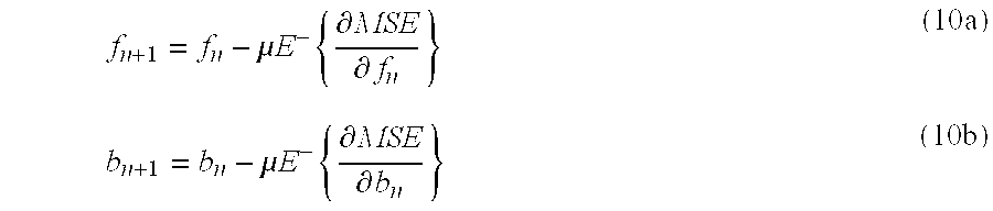
- wherein MSE is defined in Equ. (9c), μ is the LMS step-size and E − denotes dropping the statistical expectation in the definition of Equ. (9c). Calculating the partial derivatives results in:
- f n+1 =f n +μX n e n*; (11)
-

- When the value of μ is chosen suitably small, the sequence of iterations defined by Equ. (11) through Equ. (13) is stable and converges to the set of coefficients which solve Equ. (4). Notice that this sequence of iterations does not require explicitly estimating the covariances and cross-covariances in Equ. (4).
- FIG. 6 illustrates an LMS algorithm according to one embodiment. The
algorithm 500 starts with selection of an initial SINR0 value atstep 502. Additionally, the index k is initialized as k=0. Atstep 504, the value of SINRk is estimated and α(SINRk) is calculated or determined from a pre-calculated Look-Up Table (LUT). Equ. (11) through Equ. (13) given hereinabove are calculated iteratively, based on the pilot symbols in the transmission, until a convergence criteria is met atstep 506. The result of such iteration determines the values for (fk,bk). Atstep 508 the process estimates SINRk+1, which is the SINR at the equalizer output when the FFF and FBF coefficients are (fk,bk). The estimation may be done using the pilot symbols in the transmission. The process then increments the index k. On convergence of SINRk atdecision diamond 510, the process continues to step 512 to apply the filter coefficients. Else, processing returns to step 504. - Algorithm with Periodic Pilot Bursts: According to another embodiment, a communication system incorporates periodically transmitted pilot bursts which are used by receivers to adjust the filter coefficients in the receivers' equalizer. Such adjustment is often referred to as “training the equalizer”. An example of such a system is a system supporting High Data Rate (HDR) as defined in “TIA/EIA-IS-856 CDMA2000 High Rate Packet Data Air Interface Specification” (the IS-856 standard). In an HDR system, 96 pilot symbols are transmitted every 0.833 ms. Each group of 96 pilot symbols is referred to as a “pilot burst”. In between pilot bursts, the HDR system transmits data symbols intended for receivers. FIG. 7 illustrates an algorithm for applying an LMS-based hybrid DFE in such a system. The
algorithm 600 initially sets up SINR0 as equal to 0 or ∞ atstep 602. The initial choice of SINR is not designated and may not be critical, though for the fastest convergence, SINR0 equal to ∞ may be preferred. The index k is also initialized and set equal to 0. Atstep 604 the algorithm determines SINRk, and computes α(SINRk) or determines the necessary value by consulting a pre-calculated Look-Up Table. The initial values for f and b are set as f0=0 and b0=0 atstep 606. During the (k+1)-th pilot burst, the process iterates Equations (11) through (13) for all chips of the pilot burst,step 608. In the present HDR example, thealgorithm 600 iterates for 96 chips of the pilot burst and the final values of f and b are saved. Atstep 610 the process estimates SINRk+1, using the 96 chips of the preceding pilot burst. During the data portion following the (k+1) pilot burst, the saved values of f and b are loaded into the FFF and the FBF and the data symbols are equalized in standard decision-feedback fashion. Atstep 614 the process computes the value of α(SINRk+1) and increments k. The process continues to implement the algorithm during demodulation operations. - The algorithm of FIG. 7 is adaptive for slowly time-varying channels, as quasi steady state SINR k, and therefore, α(SINRk), are not expected to vary much over the convergence time of the LMS algorithm.
- Soft Slicer: As discussed hereinabove, error propagation significantly limits the use of DFEs in communication systems employing channel coding. Because the causal ISI is cancelled by feeding back decisions on individual symbols, a single isolated decision error may lead to a burst of subsequent decision errors, greatly enhancing the residual interference at the equalizer's output. If the channel code is strong, the probability of a symbol decision error is non-negligible (typically on the order of 25 percent) and error propagation may have serious effects on the performance of the DFE. One method of avoiding the effects incurred by such error propagation is to recognize that the usual “minimum distance” slicer attaches no confidence-level to symbol decisions. In other words, conventional slicer decisions provide no measure of the accuracy or correctness of symbol decisions. If a decision were known to be of questionable accuracy, it might be better to avoid canceling that symbol's contribution to the post-cursor tail, rather than risk compounding the residual interference by subtracting an incorrect decision. In other words, symbol decisions of low accuracy should not be included in the feedback loop canceling causal ISI
- One embodiment of a slicer that incorporates a confidence-level into the decision process will be referred to herein as a “soft slicer.” One soft slicer is described by a mathematical model as explained hereinbelow. First, assume the input symbol to the slicer is given as:
- ŷ=y+n (14)
- where y is the transmitted symbol belonging to the constellation Ψ, and n consists of residual noise and intersymbol interference. Assume that y is uniformly distributed over Ψ so that all constellation points are transmitted with equal probability. Let L(y,{tilde over (y)}) be a loss function measuring the loss incurred when a slicer decides {tilde over (y)} when the transmitted symbol is y. An optimum slicer σ:ŷ→{tilde over (y)}, wherein “optimum” refers to a slicer which minimizes Expected loss, is given by Bayes Rule:

- For the Minimum Error Probability (MEP) loss function given as:

- the expected loss results in:

- and therefore:

- Additionally, assuming the interference n is a Gaussian random variable with zero mean and variance σ 2, then:

- independent of σ 2. This is a traditional “minimum distance” slicer, and although it is “Bayes-optimum” for the loss function of Equ. (16), the slicer may lead to error propagation for the reasons discussed hereinabove. An alternate slicer design considers the quadratic loss function:
- L(y,{tilde over (y)})=∥y−{tilde over (y)}∥2 (20)
- which, unlike the MEP loss function, penalizes larger errors more significantly than smaller errors. Following from Equ. (15):

- and the conditional mean equals:

- An important observation is that unlike the slicer of Equ. (19), the slicer of Equ. (22) requires an estimate of the interference and noise variance σ 2 (e.g.,

- Note also that the slicer of Equ. (22) corresponds to the centroid of the a posteriori distribution on the constellation symbols, i.e., the centroid of the term in square brackets [. . . ] in Equ. (22). Thus if σ 2 is large, the assumption of a uniform prior distribution on a symmetric constellation implies a nearly uniform posterior distribution, and hence the centroid is near zero. On the other hand, when σ2 is small, the posterior distribution has its mass concentrated on the actual transmitted symbol and its neighboring constellation points; the centroid is therefore, close to the transmitted symbol. The slicer in Equ. (22) is thus referred to as a “soft slicer”.
- The soft slicer can be used in the adaptive Hybrid DFE with minimum modification. The FFF and FBF coefficients are chosen to optimize the following definition of MSE:
- MSE=E|y n −f H X n b H Z n|2+(1+2ρQ−λQ 2)∥b∥2 (23)
- where
- ρQ =E Q ={{tilde over (Y)}*Y} (24a)
- similar to Equ. (5), and λ Q 2 is defined as:
- λQ 2 =E Q {|{tilde over (Y)}| 2} (24b)
- The “channel” Q({tilde over (y)}|y) is defined as:
- Q({tilde over (y)}|y)=Pr{σ(y+Z)={tilde over (y)}} (25)
- wherein σ(.) represents the soft-slicer defined in Equ. (22) and Z is complex gaussian noise defined in exactly the same way as in Equ. (7). Following an analogous development of the optimization scheme based on the LMS algorithm, we find Equs. (11), (12) and (13) unchanged, except that for the fact that α Q=1+λQ 2−2ρQ is computed based on Equs. (24a), (24b) and the soft-slicer defined in Equ. (25). As before, the leakage factor (1−2ρQ+λQ 2) is SINR dependent and may be determined by a table lookup.
- The LMS-based algorithm as described hereinabove requires no additional changes. During the pilot training portion of the slot, the adaptation is performed as before; during the data portion of the slot, the conditional mean slicer is used in place of the “hard”, minimum-distance slicer.
- The computations involved in the soft slicer, namely Equ. (22), may be too complicated for some practical implementations. One embodiment simplifies the slicer design so as to restrict the slicer output to take on at most N values. Equivalently, this amounts to restricting the slicer input to take on at most N values. In other words, the slicer input Ŷ is quantized to one of N points using a quantizer defined by: Q:Ŷ→{Ŷ l, . . . , ŶN}. Then for k=1, . . . , N, σ(Ŷ) is computed as:
- σ(Ŷ)=σk, if Q(Ŷ)=Ŷk (26)
- wherein:
- σk =E{Y|Ŷ∈Q −1(Ŷk)}. (27)
- The quantized slicer's operation can be summarized as: 1) quantize Ŷ to one of N possible values; and 2) use this value and knowledge of the SINR as indices in a lookup table to determine {overscore (Y)}=σ(Ŷ). Since the complexity in this design lies in step 1), a further simplification would be to restrict Ŷ1, . . . , ŶN to lie on a uniform square grid and then quantize Ŷ by quantizing its Real and Imaginary parts separately, using a “nearest neighbor” criterion. Such a slicer function may be implemented with simple logic, i.e., by first computing the nearest set of neighbors based on Ŷ's Real-coordinate, then computing the nearest neighbor in this subset based on Ŷ's Imaginary-coordinate. Additionally, the lookup table may be fairly coarse in SINR, with 1 dB steps sufficient for most implementations. For example, given {σk} lookup tables for SINR=5 dB and SINR=6 dB, the appropriate σk values for an intermediate SINR value of say, 5.4 dB, may be determined by suitably interpolating between the two LUTs. In other words, the appropriate σk values at intermediate SINR values may be generated within the slicer device, thus reducing the necessary memory/storage requirements.
- As an illustration of the application of a soft slicer to a Hybrid DFE (HDFE), consider FIGS. 8A and 8B. FIG. 8A illustrates an 8-PSK constellation, wherein 8 complex symbols represent the 3 encoded bits mapped for modulation. As illustrated, the circles represent the constellation points used for modulation at the transmitter. The “x” marks indicate the samples as received at the receiver and include noise and interference introduced during transmission. Note that the received samples do not necessarily match the actual constellation symbols. In this case, the receiver decides which constellation symbol was actually sent. Typically, the received points are concentrated around the actual transmitted constellation symbols.
- One method of determining the transmitted symbol from the received samples is to divide the constellation map into pie slices, as illustrated in FIG. 8B. Here the constellation map is divided into 8 slices, 702, 704, 706, 708, 710, 712, 714, and 716. The slices are determined, for example, in accordance with a minimum distance metric, which uses the Euclidean distance or separation between two constellation points to select a boundary. A problem exists when the received sample is approximately equidistant (i.e., approximately on the boundary) between two constellation points. In this case, if the decision process were to select the wrong constellation symbol, this error would be propagated in the feedback loop of a DFE. To avoid such errors and the associated amplification in a DFE, a soft slicer is applied that outputs a value not necessarily at a constellation symbol. The soft slicer implicitly determines a confidence level from the received samples. The confidence level provides the system with guidance in evaluating the sample. If the confidence level is low, i.e., an error is likely, the sample is not emphasized in the feedback portion of the equalizer. If the confidence level is high, the sample is considered reliable, and therefore, a suitable symbol estimate derived therefrom may be used in the feedback portion of the equalizer.
- FIG. 9A illustrates a 2-PSK constellation map. Note that decisions made based on the minimum distance from a constellation symbol may result in errors for received samples such as that marked by the “x.” Application of a soft slicer according to one embodiment, divides the constellation map into rectangles as illustrated in FIG. 9B. As plotted, the rectangles, such as
rectangle 720, are semi-infinite in the y-direction and not all rectangles encompass constellation symbols. When the slicer's input sample falls within one of the semi-infinite rectangles, a conditional mean value is assigned. Effectively all points within the rectangle are mapped to a common value. This value represents the conditional mean of the transmitted symbol, given the slicer's input sample falls within the rectangle of interest. The mapping of each rectangle to a corresponding conditional mean value is a function of the Signal to Interference and Noise Ratio (SINR). For example, a given rectangle may map to σ for SINR at a first level, e.g., SINR=4 dB. The same rectangle may map to σ′ for SINR at a second level, e.g., SINR=5 dB. The mapping and associated conditional mean values are stored in lookup tables for easy retrieval. An alternate embodiment calculates the conditional mean value according to a predetermined algorithm. Note that a square or rectangular grid is easily implemented and extensible to more complex constellations. - FIG. 10 illustrates an
Equalizer 800 using a soft slicer. TheEqualizer 800 includes anFFF 802 coupled to a summingnode 804. TheFFF 802 is controlled by anadaptive equalization algorithm 808. Theadaptive control unit 808 is responsive to anSINR estimation unit 816. In an alternate embodiment, theSINR estimation unit 816 may be implemented as an MSE estimation unit. TheSINR estimation unit 816 provides an SINR estimate to a lookup table (LUT) 810. The SINR estimate is used in conjunction with the values stored inLUT 810 to determine αQ(SINR)=1+λQ 2−2ρQ defined according to Equs. (24a), (24b) and (25). Theadaptive equalization algorithm 808 uses the αQ value produced fromLUT 810 to update the coefficients of theFFF 802 and theFBF 806, by iterating Equs. (11), (12) and (13). Recall that Equs. (11), (12) and (13) were based on the LMS algorithm and designed to optimize the MSE cost function defined in Equ. (23). In an alternate embodiment, theadaptive equalization algorithm 808 may implement another adaptive filtering algorithm, such as RLS, to optimize the MSE cost function defined in Equ. (23). TheFBF 806 outputs an estimate of the causal ISI present in the output of theFFF 802. TheFBF 806 output is coupled to summingnode 804 where it is subtracted from the output ofFFF 802. The output of summingnode 804, i.e., the estimate of transmitted symbol, is then provided to adecoder 820, the SINR/MSE estimation unit 816, and to thesoft slicer 812. Thesoft slicer 812 receives the SINR/MSE estimate from the SINR/MSE estimation unit 816 and generates a further estimate of the transmitted symbol, and outputs this further symbol estimate for filtering inFBF 806. - FIG. 11 is a flow chart of a soft slicer process incorporating a soft slicer according to one embodiment. The process first determines a region, such as a grid square or rectangle on the constellation map, corresponding to a quantization of the slicer input sample ŷ, at
step 902. A determination is made of the SINR value atstep 904. Atstep 906, the process selects an appropriate mapping as a function of the SINR value. According to one embodiment, separate portions of a memory storage device store separate look up tables. The tables are accessed according to SINR value. At step 908 a conditional mean value is determined from the appropriate mapping and this is the slicer output. - Another soft slicer embodiment applies a square grid to the constellation map, and uses a Taylor expansion to generate a more accurate conditional mean value. In this embodiment, multiple smaller lookup tables store values corresponding to each SINR value. The
process 920 is illustrated in FIG. 12. The region of the soft slicer input ŷ is determined atstep 921. Atstep 922 an SINR value is determined. The SINR value is used to determine appropriate mappings σ1(.) and σ2(.) atstep 924. The region ofstep 920 is mapped to a value σ1(ŷi), wherein i corresponds to the region. A second mapping is then performed atstep 922 consistent with the SINR value and the region ofstep 920 to obtain σ2(ŷi). A conditional mean value is approximated atstep 928 as σ1(ŷi)+(ŷ−ŷi)σ2(ŷi). The mappings σ1(.) and σ2(.) are closely related to the zero-th and first derivatives of σ(.) defined in Equ. (22). - FIG. 13 illustrates a
soft slicer 954 according to one embodiment. AnSINR estimator 952 receives one or more symbol estimates and outputs an SINR estimate value SINR(n). The SINR(n) may be quantized in anoptional quantizer 956, and is provided tomemory storage 960, such as a LUT. A symbol estimate corresponding to the soft slicer input is also provided to aquantizer 956, wherein the symbol estimate is quantized and the quantized value is used in conjunction with the SINR estimate to determine a corresponding value stored in thememory storage 960. Note that in one embodiment, the information is stored in rows and columns, wherein the rows correspond to SINR values and the columns correspond to symbol values. Alternate embodiments, however, may store the information in any of a variety of ways, wherein the information is retrievable based on an SINR value and a symbol value. The values stored in thememory storage 960 may be the conditional mean of actual constellation symbol, given the soft slicer input estimate, such as defined in Equs. (22), (26) and. (27). FIG. 14 illustrates asoft slicer 980 according to an alternate embodiment implementing a Taylor series computation. As illustrated, one or more received symbols are provided to anSINR estimator 982 and one symbol estimate, corresponding to the soft slicer input, is also provided directly to thesoft slicer 980. Note that the received symbols are corrupted by the transmission channel and therefore are herein also referred to as received “samples.” TheSINR estimator 982 provides an SINR estimate SINR(n) to thesoft slicer 980. The SINR(n) may be provided to anoptional quantizer 986. The SINR(n), quantized or not, is provided to two memory storage units, A 988 andB 990. The soft slicer input symbol estimate is provided to aquantizer 984, the output of which is also provided to the memory storage units A 988 andB 990. The memory storage units A 988 andB 990 store information used to compute the conditional mean values of the actual constellation symbol, given the soft slicer input symbol estimate. Such values may be the zero-th and first derivatives of the conditional mean of the actual constellation symbol, given the soft slicer input symbol estimate, such as given in Equs. (22), (26) and Equ. (27). The SINR(n) value and the quantized symbol value are used to identify the corresponding values inmemory storage A 988 andB 990. A summingunit 992 is used to implement the Taylor series computation. The soft slicer input symbol estimate, as well as the quantized value are provided to the summingunit 992. In addition, the values stored in the memory storage units A 988 andB 990 are also provided to summingunit 992. The summingunit 992 uses the inputs to compute an output that is a conditional mean estimate of the actual constellation symbol. While the present invention has been described with respect to a wireless communication system, such a system is provided merely as an example. The concepts described herein are applicable in a variety of communication systems, including, but not limited to wireline communication system, such as implementation in a wireline modem, etc. The present invention is applicable in a high data rate communication system, and allows optimization of resources and capacity in a data communication system by increasing receiver sensitivity and increasing the communication data rate. Those of skill in the art would understand that information and signals may be represented using any of a variety of different technologies and techniques. For example, data, instructions, commands, information, signals, bits, symbols, and chips that may be referenced throughout the above description may be represented by voltages, currents, electromagnetic waves, magnetic fields or particles, optical fields or particles, or any combination thereof. - Those of skill would further appreciate that the various illustrative logical blocks, modules, circuits, and algorithm steps described in connection with the embodiments disclosed herein may be implemented as electronic hardware, computer software, or combinations of both. To clearly illustrate this interchangeability of hardware and software, various illustrative components, blocks, modules, circuits, and steps have been described above generally in terms of their functionality. Whether such functionality is implemented as hardware or software depends upon the particular application and design constraints imposed on the overall system. Skilled artisans may implement the described functionality in varying ways for each particular application, but such implementation decisions should not be interpreted as causing a departure from the scope of the present invention.
- The various illustrative logical blocks, modules, and circuits described in connection with the embodiments disclosed herein may be implemented or performed with a general purpose processor, a digital signal processor (DSP), an application specific integrated circuit (ASIC), a field programmable gate array (FPGA) or other programmable logic device, discrete gate or transistor logic, discrete hardware components, or any combination thereof designed to perform the functions described herein. A general purpose processor may be a microprocessor, but in the alternative, the processor may be any conventional processor, controller, microcontroller, or state machine. A processor may also be implemented as a combination of computing devices, e.g., a combination of a DSP and a microprocessor, a plurality of microprocessors, one or more microprocessors in conjunction with a DSP core, or any other such configuration.
- The steps of a method or algorithm described in connection with the embodiments disclosed herein may be embodied directly in hardware, in a software module executed by a processor, or in a combination of the two. A software module may reside in RAM memory, flash memory, ROM memory, EPROM memory, EEPROM memory, registers, hard disk, a removable disk, a CD-ROM, or any other form of storage medium known in the art. An exemplary storage medium is coupled to the processor such the processor can read information from, and write information to, the storage medium. In the alternative, the storage medium may be integral to the processor. The processor and the storage medium may reside in an ASIC. The ASIC may reside in a user terminal. In the alternative, the processor and the storage medium may reside as discrete components in a user terminal.
- The previous description of the disclosed embodiments is provided to enable any person skilled in the art to make or use the present invention. Various modifications to these embodiments will be readily apparent to those skilled in the art, and the generic principles defined herein may be applied to other embodiments without departing from the spirit or scope of the invention. Thus, the present invention is not intended to be limited to the embodiments shown herein but is to be accorded the widest scope consistent with the principles and novel features disclosed herein.
Claims (21)
1. A method for determining filter coefficients in a decision-feedback equalizer, the decision-feedback equalizer having a feedforward filter and a feedback filter each defined by a plurality of coefficients, the method comprising:
selecting a cost function for the decision-feedback equalizer, the cost function is the Mean Squared Error (MSE) between an equalizer output assuming error-free feedback and a target equalizer output plus a modified measure of the energy of the feedback filter coefficients; and
adjusting the plurality of coefficients until a convergence condition is met, wherein the convergence condition is to minimize the cost function.
2. The method as in claim 1 , wherein the plurality of coefficients correspond to a plurality of filter taps, and wherein the modified measure of energy is a function of at least one of the filter taps.
3. The method as in claim 1 , wherein the cost function is a MSE given as:

wherein yn is a transmitted symbol, N corresponds to a number received symbols, Xn are the contents of the feedforward filter at time n, Zn are the feedback filter contents assuming error-free feedback, f are filter coefficients for the feedforward filter, b are filter coefficients for the feedback filter, and Δ//b//2 is the modified measure of energy of the feedback filter coefficients.
4. The method as in claim 3 , wherein the modified measure α is given as:
α=1+λQ 2−2ρQ,
wherein ρQ is a measure of the cross-correlation of the input and output of a slicer model, and
wherein λQ 2 is a measure of the mean output energy of a slicer model.
5. The method as in claim 3 , wherein the cost function is minimized using a Least Mean Square algorithm.
6. The method as in claim 3 , further comprising:
generating an estimate of the MSE between a equalizer output and a target equalizer output; and
selecting α as a function of the estimate of the MSE.
7. The method as in claim 3 , further comprising:
generating an estimate of a Signal-to-Interference and Noise Ratio (SINR) at an output of the equalizer; and
selecting α as a function of the estimate of the SINR.
8. A method as in claim 3 , wherein α=2m,m=integer.
9. The method as in claim 3 , wherein the modified measure α is defined as:
α=1+λQ 2−2ρQ
wherein:

wherein Q({tilde over (y)}|y) is a slicer channel model, {tilde over (y)} is a slicer output and y is a slicer input.
10. The method as in claim 9 , wherein the slicer channel model is defined as:
Q({tilde over (y)}|y)=Pr{σ(y+Z)={tilde over (y)}}
where σ(.) denotes a minimum distance slicing function, Z is a zero mean Gaussian random variable, y is a slicer input, and {tilde over (y)} is a slicer output.
11. The method as in claim 9 , comprising:
estimating Signal-to-Interference and Noise Ratio (SINR) of a pilot signal at an output of a equalizer.
12. The method as in claim 3 , wherein the cost function optimizations comprise:
using a Least Mean Square (LMS) algorithm to determine filter coefficients and an error term and iteratively compute equations:
f n+1 =f n +μX n e n*;b n+1=(1−μα)b n +μZ n e n*; ande n +y n −f n H X n −b n H Z n,
wherein f represents filter coefficients of the feed-forward filter, b represents filter coefficients of the feed-back filter, X represents feed-forward filter contents, α represents a factor modifying the energy of the feed-back filter coefficients, e represents the error term, Z represents feed-back filter contents assuming error-free feedback, y represents a desired symbol, and μ represents the LMS step size.
13. The method as in claim 3 , wherein the cost function is minimized using a Recursive Least Squares algorithm.
14. A decision-feedback equalizer, comprising:
a feedforward filter having a plurality of filter taps, the filter taps having corresponding filter coefficients;
a feedback filter having a plurality of filter taps, the filter taps having corresponding filter coefficients
a coefficient generator coupled to the feedforward filter and the feedback filter, adapted to update the filter coefficients of the feedforward filter and the feedback filter to minimize a predetermined cost function, wherein the cost function is a Mean Squared Error (MSE) between an equalizer output assuming error-free feedback and a target equalizer output, plus a modified measure of energy of the feedback filter coefficients;
a summing node coupled to an output of the feedforward filter and an output of the feedback filter, the summing node configured to subtract the output of the feedback filter from the output of the feedforward filter, to generate an estimate of an original transmitted symbol; and
a slicer coupled to the summing node, the slicer adapted to receive the estimate and determine the original transmitted symbol.
15. The decision-feedback equalizer as in claim 14 , wherein the coefficient generator is adapted to:

estimate a Signal-to-Interference and Noise Ratio (SINR) of a pilot signal at an output of the decision-feedback equalizer; and
determine a modified measure α defined as:
α=1+λQ 2−2ρQ
wherein:
wherein Q({tilde over (y)}|y) is a slicer channel model, {tilde over (y)} is a slicer output,
wherein the slicer channel model is defined as:
Q({tilde over (y)}|y)=Pr{σ(y+Z)={tilde over (y)}}
where σ(.) denotes a minimum distance slicing function, Z is a zero mean Gaussian random variable, y is a slicer input, and {tilde over (y)} is a slicer output.
16. The decision-feedback equalizer as in claim 15 , wherein the coefficient generator is further adapted to:
determine the modified measure using a memory storage device storing modified measures as a function of SINR.
17. The decision-feedback equalizer as in claim 15 , wherein the coefficient generator is adapted to:

estimate a Mean Squared Error (MSE) between an equalizer output assuming error-free feedback and a target equalizer output; and
determine a modified measure α defined as:
α=1+λQ 2−2ρQ
wherein:
18. The decision-feedback equalizer as in claim 17 , wherein the coefficient generator is further adapted to:
determine the modified measure using a memory storage device storing modified measures as a function of MSE.
19. A method for determining filter coefficients in a decision-feedback equalizer, the decision-feedback equalizer having a feedforward filter and a feedback filter each defined by a plurality of coefficients, the method comprising:
selecting a cost function for the decision-feedback equalizer, the cost function is the Mean Squared Error (MSE) between an equalizer output assuming error-free feedback and a target equalizer output plus a modified measure of energy of the feedback filter coefficients; and
adjusting the plurality of coefficients according to a Recursive Least Squares (RLS) algorithm.
20. An apparatus, comprising:
processing unit; and
memory storage unit coupled to the processing unit, the memory storage unit storing computer-readable instructions, comprising:
a first set of instructions for determining filter coefficients in a decision-feedback equalizer having a feedforward filter and a feedback filter each defined by a plurality of coefficients, by selecting a cost function for the decision-feedback equalizer, the cost function defined as the Mean Squared Error (MSE) between an equalizer output assuming error-free feedback and a target equalizer output plus a modified measure of energy of the feedback filter coefficients; and
a second set of instructions for adjusting the plurality of coefficients until a convergence condition is met, wherein the convergence condition is to minimize the cost function.
21. An apparatus, comprising:
processing unit; and
memory storage unit coupled to the processing unit, the memory storage unit storing computer-readable instructions, comprising:
a first set of instructions for determining filter coefficients of a differential feed-back equalizer having a feed-back filter and a feed-forward filter, and an error term by application of a Least Mean Square (LMS) algorithm to iteratively compute equations:
f n+1 =f n +μX n e n*;b n+1=(1−2μ(1−ρQ))b n +μZ n e n; ande n =y n −f n H X n −b n H Z n,
wherein f represents filter coefficients of the feed-forward filter, b represents filter coefficients of the feed-back filter, X represents feed-forward filter contents, ρ represents a correlation between a slicer output of the differential feed-back equalizer and a transmitted signal, e represents the error term, Z represents feed-back filter contents assuming error-free feedback, y represents a received sample, and μ represents an LMS step size.
Priority Applications (32)
| Application Number | Priority Date | Filing Date | Title |
|---|---|---|---|
| US10/199,159 US7046726B2 (en) | 2002-07-18 | 2002-07-18 | Method and apparatus for hybrid decision feedback equalization |
| RU2005104433/09A RU2328081C2 (en) | 2002-07-18 | 2003-07-18 | Hybrid correction method and unit with decision feedback |
| CN2009100047454A CN101499983B (en) | 2002-07-18 | 2003-07-18 | Method and apparatus for hybrid decision feedback equalization |
| EP10175826A EP2254295B1 (en) | 2002-07-18 | 2003-07-18 | Method for decision feedback equalization |
| ES03765773T ES2365730T3 (en) | 2002-07-18 | 2003-07-18 | PROCEDURE AND APPLIANCE FOR A DECISION FEEDBACK EQUALIZATION. |
| AT08010035T ATE506792T1 (en) | 2002-07-18 | 2003-07-18 | METHOD AND APPARATUS FOR USE IN DECISION FEEDBACK EQUALIZATION |
| EP03765773A EP1525727B1 (en) | 2002-07-18 | 2003-07-18 | Method and apparatus for decision feedback equalization |
| DE60336903T DE60336903D1 (en) | 2002-07-18 | 2003-07-18 | METHOD AND DEVICE FOR DECISION-RECONCITED DECELERATION |
| AT03765773T ATE507639T1 (en) | 2002-07-18 | 2003-07-18 | METHOD AND DEVICE FOR DECISION FEEDBACK EQUALIZATION |
| CN03816692A CN100583853C (en) | 2002-07-18 | 2003-07-18 | Method and apparatus for hybrid decision of feedback equalization |
| AT10175826T ATE527792T1 (en) | 2002-07-18 | 2003-07-18 | METHOD FOR DECISION FEEDBACK EQUALIZATION |
| KR1020057000645A KR101013628B1 (en) | 2002-07-18 | 2003-07-18 | Method and apparatus for hybrid decision feedback equalization |
| ES08010035T ES2368120T3 (en) | 2002-07-18 | 2003-07-18 | PROCEDURE AND APPLIANCE FOR USE IN A DECISION FEEDBACK EQUALIZATION. |
| BRPI0312747A BRPI0312747B1 (en) | 2002-07-18 | 2003-07-18 | method and equipment for hybrid decision feedback equalization |
| EP10175819A EP2254293A3 (en) | 2002-07-18 | 2003-07-18 | Method and apparatus for decision feedback equalization |
| EP08010035A EP1956783B1 (en) | 2002-07-18 | 2003-07-18 | Method and apparatus for use in decision feedback equalization |
| EP10175823A EP2254294A3 (en) | 2002-07-18 | 2003-07-18 | Method and apparatus for decision feedback equalization |
| TW092119728A TWI317589B (en) | 2002-07-18 | 2003-07-18 | Method and apparatus for hybrid decision feedback equalization |
| JP2004523610A JP4373330B2 (en) | 2002-07-18 | 2003-07-18 | Method and apparatus for hybrid decision feedback equalization |
| DE60336863T DE60336863D1 (en) | 2002-07-18 | 2003-07-18 | Method and apparatus for use in decision feedback equalization |
| CA2493106A CA2493106C (en) | 2002-07-18 | 2003-07-18 | Method and apparatus for hybrid decision feedback equalization |
| AU2003256623A AU2003256623C1 (en) | 2002-07-18 | 2003-07-18 | Method and apparatus for hybrid decision feedback equalization |
| PCT/US2003/022594 WO2004010665A2 (en) | 2002-07-18 | 2003-07-18 | Method and apparatus for hybrid decision feedback equalization |
| MXPA05000707A MXPA05000707A (en) | 2002-07-18 | 2003-07-18 | Method and apparatus for hybrid decision feedback equalization. |
| IL16586804A IL165868A0 (en) | 2002-07-18 | 2004-12-19 | Method and apparatus for hybrid decision feedback equalization |
| NO20050863A NO20050863L (en) | 2002-07-18 | 2005-02-17 | Hybrid signal equalization on feedback |
| RU2005120491/09A RU2407197C2 (en) | 2002-07-18 | 2005-06-30 | Method and device for hybrid correction with decision feedback |
| JP2009132927A JP4902696B2 (en) | 2002-07-18 | 2009-06-02 | Method and apparatus for hybrid decision feedback equalization |
| IL202168A IL202168A (en) | 2002-07-18 | 2009-11-16 | Method and apparatus for determining filter coefficients in a decision-feedback equalizer |
| JP2011180517A JP5405541B2 (en) | 2002-07-18 | 2011-08-22 | Method and apparatus for hybrid decision feedback equalization |
| JP2013122368A JP5694444B2 (en) | 2002-07-18 | 2013-06-11 | Method and apparatus for hybrid decision feedback equalization |
| JP2014161197A JP5855716B2 (en) | 2002-07-18 | 2014-08-07 | Method and apparatus for hybrid decision feedback equalization |
Applications Claiming Priority (1)
| Application Number | Priority Date | Filing Date | Title |
|---|---|---|---|
| US10/199,159 US7046726B2 (en) | 2002-07-18 | 2002-07-18 | Method and apparatus for hybrid decision feedback equalization |
Publications (2)
| Publication Number | Publication Date |
|---|---|
| US20040013190A1 true US20040013190A1 (en) | 2004-01-22 |
| US7046726B2 US7046726B2 (en) | 2006-05-16 |
Family
ID=30443242
Family Applications (1)
| Application Number | Title | Priority Date | Filing Date |
|---|---|---|---|
| US10/199,159 Active 2024-05-01 US7046726B2 (en) | 2002-07-18 | 2002-07-18 | Method and apparatus for hybrid decision feedback equalization |
Country Status (3)
| Country | Link |
|---|---|
| US (1) | US7046726B2 (en) |
| ES (1) | ES2368120T3 (en) |
| TW (1) | TWI317589B (en) |
Cited By (35)
| Publication number | Priority date | Publication date | Assignee | Title |
|---|---|---|---|---|
| US20040170233A1 (en) * | 2003-02-27 | 2004-09-02 | Onggosanusi Eko N. | Symbol normalization in MIMO systems |
| US20040179582A1 (en) * | 2003-01-15 | 2004-09-16 | Sony Corporation | Communication apparatus and communication method |
| US20050232348A1 (en) * | 2004-04-15 | 2005-10-20 | Mediatek Incorporation | Apparatus and method for error propagation reduction in a decision feedback equalizer |
| US20050249314A1 (en) * | 2003-09-25 | 2005-11-10 | Christian Bock | Method and circuit arrangement for deciding a symbol in the complex phase space of a quadrature modulation method |
| US20060176948A1 (en) * | 2005-02-04 | 2006-08-10 | Dong-Hoon Lee | Decision-feedback channel equalizer usable with a digital receiver and method thereof |
| US20060203900A1 (en) * | 2005-03-10 | 2006-09-14 | Stmicroelectronics, Inc. | Burst error limiting feedback equalizer system and method for multidimensional modulation systems |
| WO2006105309A1 (en) * | 2005-03-29 | 2006-10-05 | Qualcomm Incorporated | Method and apparatus for block-wise decision-feedback equalization for wireless communication |
| US20060227854A1 (en) * | 2005-04-07 | 2006-10-12 | Mccloud Michael L | Soft weighted interference cancellation for CDMA systems |
| US20060227909A1 (en) * | 2005-04-07 | 2006-10-12 | Thomas John K | Optimal feedback weighting for soft-decision cancellers |
| US20060233222A1 (en) * | 2005-04-14 | 2006-10-19 | Telefonaktiebolaget Lm Ericsson (Publ) | SIR prediction method and apparatus |
| US20070041437A1 (en) * | 2005-08-18 | 2007-02-22 | Chun-Ming Kuo | Bit error probability estimating system and related method thereof |
| US20070110131A1 (en) * | 2005-11-15 | 2007-05-17 | Tommy Guess | Iterative interference cancellation using mixed feedback weights and stabilizing step sizes |
| US20070110132A1 (en) * | 2005-11-15 | 2007-05-17 | Tommy Guess | Iterative interference cancellation using mixed feedback weights and stabilizing step sizes |
| US20070201548A1 (en) * | 2004-03-25 | 2007-08-30 | Benq Mobile Gmbh & Co. Ohg | Method and communication device for interference concellation in a cellular tdma communication system |
| US20080273481A1 (en) * | 2007-05-02 | 2008-11-06 | Mediaphy Corporation | Warm start receiver |
| US7505537B1 (en) * | 2003-03-25 | 2009-03-17 | Marvell International Ltd. | System and method for controlling gain and timing phase in a presence of a first least mean square filter using a second adaptive filter |
| US7711075B2 (en) | 2005-11-15 | 2010-05-04 | Tensorcomm Incorporated | Iterative interference cancellation using mixed feedback weights and stabilizing step sizes |
| US7715508B2 (en) | 2005-11-15 | 2010-05-11 | Tensorcomm, Incorporated | Iterative interference cancellation using mixed feedback weights and stabilizing step sizes |
| US20100208854A1 (en) * | 2005-11-15 | 2010-08-19 | Tommy Guess | Iterative Interference Cancellation for MIMO-OFDM Receivers |
| US20100215082A1 (en) * | 2005-11-15 | 2010-08-26 | Tensorcomm Incorporated | Iterative interference canceller for wireless multiple-access systems employing closed loop transmit diversity |
| US20100246998A1 (en) * | 2007-12-04 | 2010-09-30 | Huawei Technologies Co., Ltd. | Image interpolation method and apparatus, and method for obtaining interpolation coefficients |
| US20110019656A1 (en) * | 2002-09-20 | 2011-01-27 | Rambus Inc. | Advanced signal processors for Interference Cancellation in baseband receivers |
| US20110044378A1 (en) * | 2005-11-15 | 2011-02-24 | Rambus Inc. | Iterative Interference Canceler for Wireless Multiple-Access Systems with Multiple Receive Antennas |
| US20110064066A1 (en) * | 2002-09-23 | 2011-03-17 | Rambus Inc. | Methods for Estimation and Interference Cancellation for signal processing |
| US20110116464A1 (en) * | 2008-04-25 | 2011-05-19 | Ntt Docomo, Inc. | Base station apparatus and method in mobile communication system |
| US20110176636A1 (en) * | 2010-01-20 | 2011-07-21 | Hua Wang | High-efficiency all-digital transmitter |
| US20130230090A1 (en) * | 2012-01-21 | 2013-09-05 | Huawei Technologies Co., Ltd. | Adaptive equalization method and adaptive equalizer |
| US20130288193A1 (en) * | 2012-04-27 | 2013-10-31 | Scott Eric Gallacher | Apparatus and system for dental modeling |
| US8615035B2 (en) | 2005-03-29 | 2013-12-24 | Qualcomm Incorporated | Method and apparatus for block-wise decision-feedback equalization for wireless communication |
| US8779847B1 (en) | 2011-07-13 | 2014-07-15 | Marvell International Ltd. | Systems and methods for finite impulse response adaptation for gain and phase control |
| US20170163453A1 (en) * | 2015-12-02 | 2017-06-08 | Mstar Semiconductor, Inc. | Equalizing apparatus and soft decision method |
| US9768913B1 (en) | 2016-03-09 | 2017-09-19 | Samsung Electronics Co., Ltd | System and method for multiple input multiple output (MIMO) detection with soft slicer |
| EP3474507A1 (en) * | 2017-10-18 | 2019-04-24 | Cisco Technology, Inc. | Equalizer optimization for fec-protected communication links |
| US10477488B2 (en) * | 2016-04-17 | 2019-11-12 | Lg Electronics Inc. | Method for transmitting signals by considering interferences in FED2D environment and apparatus therefor |
| US11223447B1 (en) * | 2021-03-31 | 2022-01-11 | Seagate Technology Llc | Multiple detector data channel and data detection utilizing different cost functions |
Families Citing this family (7)
| Publication number | Priority date | Publication date | Assignee | Title |
|---|---|---|---|---|
| US7339988B1 (en) * | 2003-07-03 | 2008-03-04 | Scintera Networks, Inc. | Channel monitoring and identification and performance monitoring in a flexible high speed signal processor engine |
| TWI253260B (en) * | 2003-10-14 | 2006-04-11 | Realtek Semiconductor Corp | Signal processing apparatus capable of enhance correctness of feedbacked signal |
| US7302461B2 (en) * | 2003-11-26 | 2007-11-27 | Scintera Networks, Inc. | Analog delay elements |
| US8671128B1 (en) * | 2006-06-21 | 2014-03-11 | Ikanos Communications, Inc. | Method and apparatus for a finite impulse response filter |
| EP2043275B1 (en) * | 2007-09-25 | 2013-09-04 | ADTRAN GmbH | Method and device for noise processing and communication system comprising such device |
| US8098767B2 (en) | 2007-12-20 | 2012-01-17 | Qualcomm Incorporated | Receiver adjustment between pilot bursts |
| US11012272B2 (en) * | 2015-03-10 | 2021-05-18 | Qualcomm Incorporated | Channel or interference estimation for SC-FDM symbol streams |
Citations (3)
| Publication number | Priority date | Publication date | Assignee | Title |
|---|---|---|---|---|
| US5692011A (en) * | 1994-06-15 | 1997-11-25 | International Business Machines Corporation | Dual decision equalization apparatus |
| US20040013189A1 (en) * | 2002-07-18 | 2004-01-22 | Srikant Jayaraman | Soft slicer in a hybrid decision feedback equalizer |
| US6792040B1 (en) * | 1999-10-29 | 2004-09-14 | International Business Machines Corporation | Modems having a dual power mode capability and methods of operating same |
-
2002
- 2002-07-18 US US10/199,159 patent/US7046726B2/en active Active
-
2003
- 2003-07-18 ES ES08010035T patent/ES2368120T3/en not_active Expired - Lifetime
- 2003-07-18 TW TW092119728A patent/TWI317589B/en not_active IP Right Cessation
Patent Citations (3)
| Publication number | Priority date | Publication date | Assignee | Title |
|---|---|---|---|---|
| US5692011A (en) * | 1994-06-15 | 1997-11-25 | International Business Machines Corporation | Dual decision equalization apparatus |
| US6792040B1 (en) * | 1999-10-29 | 2004-09-14 | International Business Machines Corporation | Modems having a dual power mode capability and methods of operating same |
| US20040013189A1 (en) * | 2002-07-18 | 2004-01-22 | Srikant Jayaraman | Soft slicer in a hybrid decision feedback equalizer |
Cited By (85)
| Publication number | Priority date | Publication date | Assignee | Title |
|---|---|---|---|---|
| US9735816B2 (en) | 2002-09-20 | 2017-08-15 | Iii Holdings 1, Llc | Interference suppression for CDMA systems |
| US8654689B2 (en) | 2002-09-20 | 2014-02-18 | Rambus Inc. | Advanced signal processors for interference cancellation in baseband receivers |
| US9172411B2 (en) | 2002-09-20 | 2015-10-27 | Iii Holdings 1, Llc | Advanced signal processors for interference cancellation in baseband receivers |
| US20110080923A1 (en) * | 2002-09-20 | 2011-04-07 | Rambus Inc. | Interference Suppression for CDMA Systems |
| US20110019656A1 (en) * | 2002-09-20 | 2011-01-27 | Rambus Inc. | Advanced signal processors for Interference Cancellation in baseband receivers |
| US9602158B2 (en) | 2002-09-23 | 2017-03-21 | Iii Holdings 1, Llc | Methods for estimation and interference suppression for signal processing |
| US9319152B2 (en) | 2002-09-23 | 2016-04-19 | Iii Holdings 1, Llc | Method and apparatus for selectively applying interference cancellation in spread spectrum systems |
| US8391338B2 (en) | 2002-09-23 | 2013-03-05 | Rambus Inc. | Methods for estimation and interference cancellation for signal processing |
| US9954575B2 (en) | 2002-09-23 | 2018-04-24 | Iii Holdings 1, L.L.C. | Method and apparatus for selectively applying interference cancellation in spread spectrum systems |
| US8457263B2 (en) | 2002-09-23 | 2013-06-04 | Rambus Inc. | Methods for estimation and interference suppression for signal processing |
| US20110069742A1 (en) * | 2002-09-23 | 2011-03-24 | Rambus Inc. | Method and Apparatus for Interference Suppression with Efficient Matrix Inversion in a DS-CDMA System |
| US8121177B2 (en) | 2002-09-23 | 2012-02-21 | Rambus Inc. | Method and apparatus for interference suppression with efficient matrix inversion in a DS-CDMA system |
| US8090006B2 (en) | 2002-09-23 | 2012-01-03 | Rambus Inc. | Systems and methods for serial cancellation |
| US20110064066A1 (en) * | 2002-09-23 | 2011-03-17 | Rambus Inc. | Methods for Estimation and Interference Cancellation for signal processing |
| US7397841B2 (en) * | 2003-01-15 | 2008-07-08 | Sony Corporation | Wide band communication reception apparatus and method |
| US20080240206A1 (en) * | 2003-01-15 | 2008-10-02 | Sony Corporation | Communication apparatus and communication method |
| US7983321B2 (en) | 2003-01-15 | 2011-07-19 | Sony Corporation | Communication apparatus and communication method |
| US20040179582A1 (en) * | 2003-01-15 | 2004-09-16 | Sony Corporation | Communication apparatus and communication method |
| US20040170233A1 (en) * | 2003-02-27 | 2004-09-02 | Onggosanusi Eko N. | Symbol normalization in MIMO systems |
| US7505537B1 (en) * | 2003-03-25 | 2009-03-17 | Marvell International Ltd. | System and method for controlling gain and timing phase in a presence of a first least mean square filter using a second adaptive filter |
| US8005128B1 (en) | 2003-09-23 | 2011-08-23 | Rambus Inc. | Methods for estimation and interference cancellation for signal processing |
| US20050249314A1 (en) * | 2003-09-25 | 2005-11-10 | Christian Bock | Method and circuit arrangement for deciding a symbol in the complex phase space of a quadrature modulation method |
| US9413567B1 (en) | 2004-02-27 | 2016-08-09 | Marvell International Ltd. | Systems and methods for finite impulse response adaptation for gain and phase control |
| US20070201548A1 (en) * | 2004-03-25 | 2007-08-30 | Benq Mobile Gmbh & Co. Ohg | Method and communication device for interference concellation in a cellular tdma communication system |
| US8073088B2 (en) * | 2004-03-25 | 2011-12-06 | Hewlett-Packard Development Company, L.P. | Method and communication device for interference cancellation in a cellular TDMA communication system |
| US20050232348A1 (en) * | 2004-04-15 | 2005-10-20 | Mediatek Incorporation | Apparatus and method for error propagation reduction in a decision feedback equalizer |
| US20060176948A1 (en) * | 2005-02-04 | 2006-08-10 | Dong-Hoon Lee | Decision-feedback channel equalizer usable with a digital receiver and method thereof |
| US20060203900A1 (en) * | 2005-03-10 | 2006-09-14 | Stmicroelectronics, Inc. | Burst error limiting feedback equalizer system and method for multidimensional modulation systems |
| US7522663B2 (en) * | 2005-03-10 | 2009-04-21 | Stmicroelectronics, Inc. | Burst error limiting feedback equalizer system and method for multidimensional modulation systems |
| US8218615B2 (en) | 2005-03-29 | 2012-07-10 | Qualcomm Incorporated | Method and apparatus for block-wise decision-feedback equalization for wireless communication |
| EP2257007A2 (en) * | 2005-03-29 | 2010-12-01 | Qualcomm Incorporated | Method and apparatus for block-wise decision-feedback equalization for wireless communication |
| WO2006105309A1 (en) * | 2005-03-29 | 2006-10-05 | Qualcomm Incorporated | Method and apparatus for block-wise decision-feedback equalization for wireless communication |
| US8615035B2 (en) | 2005-03-29 | 2013-12-24 | Qualcomm Incorporated | Method and apparatus for block-wise decision-feedback equalization for wireless communication |
| EP2257007A3 (en) * | 2005-03-29 | 2012-02-22 | Qualcomm Incorporated | Method and apparatus for block-wise decision-feedback equalization for wireless communication |
| US10153805B2 (en) | 2005-04-07 | 2018-12-11 | Iii Holdings 1, Llc | Iterative interference suppressor for wireless multiple-access systems with multiple receive antennas |
| US9270325B2 (en) | 2005-04-07 | 2016-02-23 | Iii Holdings 1, Llc | Iterative interference suppression using mixed feedback weights and stabilizing step sizes |
| US7876810B2 (en) | 2005-04-07 | 2011-01-25 | Rambus Inc. | Soft weighted interference cancellation for CDMA systems |
| US9172456B2 (en) | 2005-04-07 | 2015-10-27 | Iii Holdings 1, Llc | Iterative interference suppressor for wireless multiple-access systems with multiple receive antennas |
| US8761321B2 (en) | 2005-04-07 | 2014-06-24 | Iii Holdings 1, Llc | Optimal feedback weighting for soft-decision cancellers |
| US20060227909A1 (en) * | 2005-04-07 | 2006-10-12 | Thomas John K | Optimal feedback weighting for soft-decision cancellers |
| US20060227854A1 (en) * | 2005-04-07 | 2006-10-12 | Mccloud Michael L | Soft weighted interference cancellation for CDMA systems |
| US9425855B2 (en) | 2005-04-07 | 2016-08-23 | Iii Holdings 1, Llc | Iterative interference suppressor for wireless multiple-access systems with multiple receive antennas |
| US7711033B2 (en) * | 2005-04-14 | 2010-05-04 | Telefonaktiebolaget Lm Ericsson (Publ) | SIR prediction method and apparatus |
| US20060233222A1 (en) * | 2005-04-14 | 2006-10-19 | Telefonaktiebolaget Lm Ericsson (Publ) | SIR prediction method and apparatus |
| US20070041437A1 (en) * | 2005-08-18 | 2007-02-22 | Chun-Ming Kuo | Bit error probability estimating system and related method thereof |
| US11296808B2 (en) | 2005-09-23 | 2022-04-05 | Iii Holdings 1, Llc | Advanced signal processors for interference cancellation in baseband receivers |
| US10666373B2 (en) | 2005-09-23 | 2020-05-26 | Iii Holdings 1, L.L.C. | Advanced signal processors for interference cancellation in baseband receivers |
| US10050733B2 (en) | 2005-09-23 | 2018-08-14 | Iii Holdings 1, Llc | Advanced signal processors for interference cancellation in baseband receivers |
| US7711075B2 (en) | 2005-11-15 | 2010-05-04 | Tensorcomm Incorporated | Iterative interference cancellation using mixed feedback weights and stabilizing step sizes |
| US20110200151A1 (en) * | 2005-11-15 | 2011-08-18 | Rambus Inc. | Iterative Interference Suppression Using Mixed Feedback Weights and Stabilizing Step Sizes |
| US20070110131A1 (en) * | 2005-11-15 | 2007-05-17 | Tommy Guess | Iterative interference cancellation using mixed feedback weights and stabilizing step sizes |
| US20070110132A1 (en) * | 2005-11-15 | 2007-05-17 | Tommy Guess | Iterative interference cancellation using mixed feedback weights and stabilizing step sizes |
| US8218697B2 (en) | 2005-11-15 | 2012-07-10 | Rambus Inc. | Iterative interference cancellation for MIMO-OFDM receivers |
| US8300745B2 (en) | 2005-11-15 | 2012-10-30 | Rambus Inc. | Iterative interference cancellation using mixed feedback weights and stabilizing step sizes |
| US8446975B2 (en) | 2005-11-15 | 2013-05-21 | Rambus Inc. | Iterative interference suppressor for wireless multiple-access systems with multiple receive antennas |
| US20100220824A1 (en) * | 2005-11-15 | 2010-09-02 | Tommy Guess | Iterative interference cancellation using mixed feedback weights and stabilizing step sizes |
| US8457262B2 (en) | 2005-11-15 | 2013-06-04 | Rambus Inc. | Iterative interference suppression using mixed feedback weights and stabilizing step sizes |
| US8462901B2 (en) | 2005-11-15 | 2013-06-11 | Rambus Inc. | Iterative interference suppression using mixed feedback weights and stabilizing step sizes |
| US7702048B2 (en) | 2005-11-15 | 2010-04-20 | Tensorcomm, Incorporated | Iterative interference cancellation using mixed feedback weights and stabilizing step sizes |
| US7715508B2 (en) | 2005-11-15 | 2010-05-11 | Tensorcomm, Incorporated | Iterative interference cancellation using mixed feedback weights and stabilizing step sizes |
| US8121176B2 (en) | 2005-11-15 | 2012-02-21 | Rambus Inc. | Iterative interference canceler for wireless multiple-access systems with multiple receive antennas |
| US20110044378A1 (en) * | 2005-11-15 | 2011-02-24 | Rambus Inc. | Iterative Interference Canceler for Wireless Multiple-Access Systems with Multiple Receive Antennas |
| US7991088B2 (en) | 2005-11-15 | 2011-08-02 | Tommy Guess | Iterative interference cancellation using mixed feedback weights and stabilizing step sizes |
| US20100208854A1 (en) * | 2005-11-15 | 2010-08-19 | Tommy Guess | Iterative Interference Cancellation for MIMO-OFDM Receivers |
| US20100215082A1 (en) * | 2005-11-15 | 2010-08-26 | Tensorcomm Incorporated | Iterative interference canceller for wireless multiple-access systems employing closed loop transmit diversity |
| US20080273481A1 (en) * | 2007-05-02 | 2008-11-06 | Mediaphy Corporation | Warm start receiver |
| US20100246998A1 (en) * | 2007-12-04 | 2010-09-30 | Huawei Technologies Co., Ltd. | Image interpolation method and apparatus, and method for obtaining interpolation coefficients |
| US8428396B2 (en) * | 2007-12-04 | 2013-04-23 | Huawei Technologies Co., Ltd. | Image interpolation method and apparatus, and method for obtaining interpolation coefficients |
| US20110116464A1 (en) * | 2008-04-25 | 2011-05-19 | Ntt Docomo, Inc. | Base station apparatus and method in mobile communication system |
| US8369239B2 (en) * | 2008-04-25 | 2013-02-05 | Ntt Docomo, Inc. | Base station apparatus and method in mobile communication system |
| WO2011091028A1 (en) * | 2010-01-20 | 2011-07-28 | Panasonic Corporation | High-efficiency all-digital transmitter |
| US8385469B2 (en) * | 2010-01-20 | 2013-02-26 | Panasonic Corporation | High-efficiency all-digital transmitter |
| CN102362472A (en) * | 2010-01-20 | 2012-02-22 | 松下电器产业株式会社 | High-efficiency all-digital transmitter |
| US20110176636A1 (en) * | 2010-01-20 | 2011-07-21 | Hua Wang | High-efficiency all-digital transmitter |
| US8779847B1 (en) | 2011-07-13 | 2014-07-15 | Marvell International Ltd. | Systems and methods for finite impulse response adaptation for gain and phase control |
| US20130230090A1 (en) * | 2012-01-21 | 2013-09-05 | Huawei Technologies Co., Ltd. | Adaptive equalization method and adaptive equalizer |
| US8982940B2 (en) * | 2012-01-21 | 2015-03-17 | Huawei Technologies Co., Ltd. | Adaptive equalization method and adaptive equalizer |
| US20130288193A1 (en) * | 2012-04-27 | 2013-10-31 | Scott Eric Gallacher | Apparatus and system for dental modeling |
| TWI623219B (en) * | 2015-12-02 | 2018-05-01 | 晨星半導體股份有限公司 | Equalizer apparatus and soft decision method |
| US9774477B2 (en) * | 2015-12-02 | 2017-09-26 | Mstar Semiconductor, Inc. | Equalizing apparatus and soft decision method |
| US20170163453A1 (en) * | 2015-12-02 | 2017-06-08 | Mstar Semiconductor, Inc. | Equalizing apparatus and soft decision method |
| US9768913B1 (en) | 2016-03-09 | 2017-09-19 | Samsung Electronics Co., Ltd | System and method for multiple input multiple output (MIMO) detection with soft slicer |
| US10477488B2 (en) * | 2016-04-17 | 2019-11-12 | Lg Electronics Inc. | Method for transmitting signals by considering interferences in FED2D environment and apparatus therefor |
| EP3474507A1 (en) * | 2017-10-18 | 2019-04-24 | Cisco Technology, Inc. | Equalizer optimization for fec-protected communication links |
| US11223447B1 (en) * | 2021-03-31 | 2022-01-11 | Seagate Technology Llc | Multiple detector data channel and data detection utilizing different cost functions |
Also Published As
| Publication number | Publication date |
|---|---|
| TW200414726A (en) | 2004-08-01 |
| ES2368120T3 (en) | 2011-11-14 |
| US7046726B2 (en) | 2006-05-16 |
| TWI317589B (en) | 2009-11-21 |
Similar Documents
| Publication | Publication Date | Title |
|---|---|---|
| US7046726B2 (en) | Method and apparatus for hybrid decision feedback equalization | |
| EP1525727B1 (en) | Method and apparatus for decision feedback equalization | |
| US7035329B2 (en) | Soft slicer in a hybrid decision feedback equalizer | |
| US9264179B2 (en) | Decision feedback equalizer for highly spectrally efficient communications | |
| Gutierrez Jr | Equalization and detection for digital communication over nonlinear bandlimited satellite communication channels |
Legal Events
| Date | Code | Title | Description |
|---|---|---|---|
| AS | Assignment |
Owner name: QUALCOMM INCORPORATED, CALIFORNIA Free format text: ASSIGNMENT OF ASSIGNORS INTEREST;ASSIGNORS:JAYARAMAN, SRIKANT;CORBATON, IVAN JESUS FERNANDEX;SMEE, JOHN E.;REEL/FRAME:013131/0376 Effective date: 20020718 |
|
| STCF | Information on status: patent grant |
Free format text: PATENTED CASE |
|
| FPAY | Fee payment |
Year of fee payment: 4 |
|
| FPAY | Fee payment |
Year of fee payment: 8 |
|
| MAFP | Maintenance fee payment |
Free format text: PAYMENT OF MAINTENANCE FEE, 12TH YEAR, LARGE ENTITY (ORIGINAL EVENT CODE: M1553) Year of fee payment: 12 |