US20040130790A1 - Random microlens array for optical beam shaping and homogenization - Google Patents
Random microlens array for optical beam shaping and homogenization Download PDFInfo
- Publication number
- US20040130790A1 US20040130790A1 US10/298,689 US29868902A US2004130790A1 US 20040130790 A1 US20040130790 A1 US 20040130790A1 US 29868902 A US29868902 A US 29868902A US 2004130790 A1 US2004130790 A1 US 2004130790A1
- Authority
- US
- United States
- Prior art keywords
- microlenses
- conforming
- sag
- profile
- boundary
- Prior art date
- Legal status (The legal status is an assumption and is not a legal conclusion. Google has not performed a legal analysis and makes no representation as to the accuracy of the status listed.)
- Granted
Links
Images


Classifications
-
- G—PHYSICS
- G02—OPTICS
- G02B—OPTICAL ELEMENTS, SYSTEMS OR APPARATUS
- G02B27/00—Optical systems or apparatus not provided for by any of the groups G02B1/00 - G02B26/00, G02B30/00
- G02B27/09—Beam shaping, e.g. changing the cross-sectional area, not otherwise provided for
- G02B27/0938—Using specific optical elements
- G02B27/095—Refractive optical elements
- G02B27/0955—Lenses
- G02B27/0961—Lens arrays
-
- G—PHYSICS
- G02—OPTICS
- G02B—OPTICAL ELEMENTS, SYSTEMS OR APPARATUS
- G02B1/00—Optical elements characterised by the material of which they are made; Optical coatings for optical elements
- G02B1/04—Optical elements characterised by the material of which they are made; Optical coatings for optical elements made of organic materials, e.g. plastics
- G02B1/041—Lenses
-
- G—PHYSICS
- G02—OPTICS
- G02B—OPTICAL ELEMENTS, SYSTEMS OR APPARATUS
- G02B27/00—Optical systems or apparatus not provided for by any of the groups G02B1/00 - G02B26/00, G02B30/00
- G02B27/09—Beam shaping, e.g. changing the cross-sectional area, not otherwise provided for
-
- G—PHYSICS
- G02—OPTICS
- G02B—OPTICAL ELEMENTS, SYSTEMS OR APPARATUS
- G02B27/00—Optical systems or apparatus not provided for by any of the groups G02B1/00 - G02B26/00, G02B30/00
- G02B27/09—Beam shaping, e.g. changing the cross-sectional area, not otherwise provided for
- G02B27/0927—Systems for changing the beam intensity distribution, e.g. Gaussian to top-hat
-
- G—PHYSICS
- G02—OPTICS
- G02B—OPTICAL ELEMENTS, SYSTEMS OR APPARATUS
- G02B3/00—Simple or compound lenses
- G02B3/0006—Arrays
- G02B3/0037—Arrays characterized by the distribution or form of lenses
- G02B3/0043—Inhomogeneous or irregular arrays, e.g. varying shape, size, height
-
- G—PHYSICS
- G02—OPTICS
- G02B—OPTICAL ELEMENTS, SYSTEMS OR APPARATUS
- G02B3/00—Simple or compound lenses
- G02B3/0006—Arrays
- G02B3/0037—Arrays characterized by the distribution or form of lenses
- G02B3/005—Arrays characterized by the distribution or form of lenses arranged along a single direction only, e.g. lenticular sheets
-
- G—PHYSICS
- G02—OPTICS
- G02B—OPTICAL ELEMENTS, SYSTEMS OR APPARATUS
- G02B3/00—Simple or compound lenses
- G02B3/0006—Arrays
- G02B3/0037—Arrays characterized by the distribution or form of lenses
- G02B3/0056—Arrays characterized by the distribution or form of lenses arranged along two different directions in a plane, e.g. honeycomb arrangement of lenses
-
- G—PHYSICS
- G02—OPTICS
- G02B—OPTICAL ELEMENTS, SYSTEMS OR APPARATUS
- G02B3/00—Simple or compound lenses
- G02B3/0006—Arrays
- G02B3/0037—Arrays characterized by the distribution or form of lenses
- G02B3/0062—Stacked lens arrays, i.e. refractive surfaces arranged in at least two planes, without structurally separate optical elements in-between
- G02B3/0068—Stacked lens arrays, i.e. refractive surfaces arranged in at least two planes, without structurally separate optical elements in-between arranged in a single integral body or plate, e.g. laminates or hybrid structures with other optical elements
Definitions
- the invention relates to optical devices based on microlens arrays that are capable of modifying or shaping intensity functions of input illumination into distinct intensity functions observed a distance away from the devices.
- the capabilities for modifying intensity functions include homogenization by reducing strong variations in the scattered intensity distribution.
- Applications of such microlens arrays include diffusers, screens, homogenizers, and beam shapers.
- Beam shaping refers to the transformation of the intensity profile of an initial input beam into a distinct profile a distance away from the beam-shaping devices. Often, beam shaping is desired in such a form that it deviates considerably from the natural shaping provided by free propagation alone (i.e., diffraction). Consequently, it often becomes necessary to employ beam-shaping devices to modify the nature of the propagating beam and thereby provide the desired shaping function.
- Gaussian diffusers which include a surface with random height variations. Ground glass and some types of chemically etched glass surfaces are used to provide such random height variations. Gaussian diffusers uniformly spread an input illumination beam over a limited angle range with Gaussian intensity profile. Such beam shapers are inexpensive and easy to fabricate but provide very limited beam-shaping capabilities.
- holographic diffusers provide some advantages over Gaussian diffusers by providing more flexibility in beam shaping, such as by spreading light with distinct angular divergence along two directions. Exact divergence can also be better controlled.
- the typical intensity scatter profile for holographic diffusers is also Gaussian.
- Other intensity profiles could in principle be obtained; but the holographic method of fabrication assumes a device with the desired intensity profile already exists, which limits the usefulness of the method.
- a zero order (straight-through) beam would also be present in addition to the desired pattern.
- Diffractive elements are also best suited for monochromatic operation and are generally designed to operate at a specific wavelength. At other wavelengths, a strong undiffracted zero-order beam component appears. Diffractive elements can be designed to operate at discrete wavelength values; but for broadband operations, such devices offer poor performance, with the zero order being the main source of degradation.
- Beam flattening such as the conversion of an incident Gaussian beam into a beam that presents flat intensity over some angular span, can also be undertaken by diffractive elements, which suffer the disadvantages mentioned previously.
- Aspheric lenses have also been used for beam flattening; but aspheric lenses present difficulties relating to fabrication, alignment, limited depth of field, and sensitivity to input beam variations.
- Regular microlens arrays have been previously used for near-field homogenization, but these arrays produce strong diffraction patterns away from the array as well as image artifacts such as moire effects in screen applications.
- Regular microlens arrays have also been used for illumination purposes but provide limited spatial shaping (polygonal energy distribution) and limited intensity control (spherical or aspheric lens profiles on a regular array) away from the array.
- the invention provides for improvements in devices containing microlens arrays for shaping illuminating beams, such that the illuminating beams traverse the devices, are modified by the devices, and recombine away from the devices according to a prescribed intensity profile within a desired far-field scatter pattern.
- the devices are based on arrays of microlenses distributed on substrates. Each microlens is defined by unique values for a set of parameters, which are generally different from the values of the same parameters that define other microlenses in the array.
- the lens-to-lens variation among the microlenses provides the means to homogenize the luminous energy away from the device.
- the shape, or sag profile, of each microlens is chosen according to a desired intensity shaping function.
- the boundary profile and spatial arrangement (relative positioning) of each microlens within the array are chosen to apply the prescribed intensity profile within the desired far-field scatter pattern.
- Optical devices arranged in accordance with the invention can be defined by an array of microlenses, where the individual microlenses differ from each other in a random manner characterized by probability distribution functions that govern parameters such as the sag profile, the boundary profile, and the spatial arrangement.
- the input beam can be shaped or modified into an output beam having a desired intensity function by control of the surface profile of each microlens and its statistical properties.
- the probability distribution functions can be chosen to further shape the intensity function, particularly with respect to rates of intensity fall off. Similar randomized variations in boundary profile (e.g., diameter) and spatial arrangement apply the desired intensity function over the desired scatter pattern.
- An optical beam shaper in keeping with a preferred embodiment of the invention provides for shaping an optical beam according to a prescribed intensity profile within a desired far-field scatter pattern.
- An array of microlenses is distributed on the substrate. Each microlens is defined within the array by values for a set of parameters that are generally different from values for the same set of parameters that define other microlenses of the array.
- the parameters include a sag profile corresponding to a surface shape of the microlenses, a boundary profile corresponding to a boundary of the microlenses, and a spatial distribution corresponding to the relative position of the microlenses within the array.
- the sag profile is varied between the microlenses of the array to homogenize the intensity profile of the optical beam.
- the boundary profile is varied between the microlenses of the array within an irregular spatial distribution to apply the prescribed intensity profile within the desired far-field scatter pattern of the optical beam.
- the sag profile is preferably varied between the microlenses of the array according to a probability distribution function. More particularly, the sag profile is preferably defined by one or more random variables that satisfy the probability distribution function within an allowed range.
- the random variables can include radii of curvature, conic constants, and aspheric coefficients of a sag function that mathematically describes the sag profile.
- the boundary profile of at least some of the microlenses is a conforming boundary that scatters evenly powered portions of the optical beam into a matching shaped far-field scatter pattern.
- the conforming boundaries preferably have polygonal, circular, or other smooth curved shapes.
- the boundary profile of other of the microlenses is a non-conforming boundary that scatters evenly powered portions of the optical beam into a far-field pattern that does not match the shape of the non-conforming boundary.
- the non-conforming boundaries generally have more complex shapes, such as piecewise curved shapes formed by contiguous sections of conforming boundaries.
- the microlenses with conforming boundaries are arranged in a spatial distribution that minimizes remaining intervening areas for the microlenses with non-conforming boundaries, which fill the spaces on the substrate in between the microlenses with conforming boundaries. Both the microlenses with conforming boundaries and the microlenses with non-conforming boundaries exhibit focusing power.
- the microlenses with conforming boundaries preferably have a random arrangement of different conformal boundaries according to a probability distribution function. For example, the different conformal boundaries can randomly vary in size within a limited range.
- the far-field scatter pattern of the optical beam is a simply connected region having a shape that matches an average shape of the microlenses with conforming boundaries.
- the far-field scatter pattern of the optical beam can also be formed as a multiply-connected region.
- the sag profile can be defined by a sag function containing a phase singularity for producing a null in the far-field scatter pattern.
- the microlenses with conforming boundaries could be grouped together and spaced apart by microlenses with non-conforming boundaries to produce spatially isolated sections of the optical beam.
- the substrate on which the microlens array is supported is preferably a transmissive substrate having opposing first and second sides.
- a diffusing element can be located on the second side of the substrate for further homogenizing or shaping the illuminating beam.
- the diffusing element can take various forms including a roughened surface, a holographically exposed pattern, a diffractive pattern, a grating, a polarizing surface, a lens, and another lens array.
- the beam shaper of the invention is particularly well suited to achieving a uniform (flat) intensity profile within the desired far-field scatter pattern, although other intensity profiles are also possible.
- the intensity fall-off rates apart from the central profile can also be controlled using probability distribution functions that exhibit differing rates of decline.
- the shape of the far-field intensity pattern can be controlled by the boundary profile and spatial distribution parameters of the microlenses. Typical far-field scatter patterns include circular, square, rectangular, and annular scatter area. Scatter patterns can also be formed with generally distinct angular divergence along two perpendicular directions.
- the far-field scatter pattern can be formed by a multiplicity of spatially separated beams with specified intensity distributions.
- Another aspect of the invention provides an apparatus for beam shaping and homogenization that includes a first random microlens array, a substrate, and a second random microlens array located on the surface opposite to the first microlens array.
- the first microlens array, substrate, and second microlens array are generally made of different materials, but can also be made of similar materials.
- the first microlens array can also differ from the second microlens array in microlens properties, distribution, and statistics.
- an apparatus for beam shaping and homogenization includes a first random microlens array, a substrate, and a second pattern located on the surface opposite to the first microlens array.
- the first microlens array, substrate, and second pattern are generally made of different materials, but can also be made of similar materials.
- the second pattern can be constituted of a variety of structures including, but not limited to, ground diffusers, holographically exposed patterns, diffractive patterns, gratings, polarizing surfaces, lenses, or lens arrays.
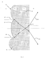
- FIGS. 1A and 1B reference a global coordinate system that locates any point in the array and coordinate frame local to each microlens unit.
- FIG. 2 is a section of a random microlens array on material of index n m , on a substrate of index n s .
- the incident and transmitted media have index n 0 . Also shown is the path for two rays through a particular microlens unit.
- FIG. 3 is a scatter pattern due to a regular array of parabolic microlenses at two distinct values of wavelength.
- FIG. 4 is a scatter pattern due to a random array of parabolic microlenses at two distinct values of wavelength. The probability distribution describing the variation of radii of curvature is uniform.
- FIG. 5 is a scatter pattern due to a random array of parabolic microlenses at two distinct values of wavelength.
- the probability distribution describing the variation of radii of curvature is a negative exponential.
- FIG. 6 is a scatter pattern due to a random array of parabolic microlenses at two distinct values of wavelength. Radii of curvature and diameters vary such that the focal location is fixed.
- FIGS. 7A and 7B are illustrations of regular tiling of the plane with circles: (FIG. 7A) square packing and (FIG. 7B) hexagonal packing.
- FIG. 8 is a unit cell of a square tiling of the plane indicating nine non-conforming regions.
- FIG. 9 is an illustration of the means to define the sag of a non-conforming region in the case of circular apertures.
- FIGS. 10 A- 10 D illustrate complete coverage of the array plane with different shapes.
- FIGS. 11 A- 11 D illustrate shapes that cannot provide complete coverage of the array plane.
- FIGS. 12A and 12B depict measured profiles of a random microlens array that projects a circle.
- FIG. 13 is an illustration of the microlens array that projects a circle with the unit cell circled by the white boundary.
- FIGS. 14A and 14B equate a measured scatter profile to a scatter pattern formed by a random microlens array that projects into a circular scatter area.
- FIGS. 15A and 15B equate a measured scatter profile to a scatter pattern formed by a random microlens array that projects into a square scatter area and uniform (flat) intensity profile.
- FIGS. 16A and 16B equate a measured scatter profile to a scatter pattern formed by a random microlens array that projects into a rectangular scatter area and uniform (flat) intensity profile.
- FIGS. 17A and 17B equate a measured scatter profile to a scatter pattern formed by a random microlens array that projects into an annular scatter area and center uniform (flat) intensity profile.
- FIG. 18 is an illustration of a random tiling of the array plane with variable-size circles.
- FIG. 19 is an illustration of a random tiling of the plane with variable-size circles and superposed cells with plane-filling square and rectangular shapes.
- FIG. 20 is an illustration of a method to cover the plane with variable-size rectangles starting from a regular square cell grid.
- FIG. 21 is an illustration of a random microlens that generates a circular scatter area with variable-size diameters and conforming shapes that deviate from the perfect circle.
- FIGS. 22 A- 22 D illustrate ( 22 A) simply-connected and ( 22 B) multiply-connected scatter regions. Also shown are illustrations of scatter patterns with a multiplicity of shapes containing individual ( 22 C) simply-connected and ( 22 D) multiply-connected regions.
- FIG. 23 is a top view of angular coordinate variation.
- FIGS. 24 A- 24 C illustrate an input beam spreading into four separate beams (a quadrupole pattern). Also shown are illustrations where the individual beams of the quadrupole present ( 24 B) circular and ( 24 C) rectangular boundaries.
- FIG. 25 is an illustration of a section of a random microlens array that generates a quadrupole and incorporates an angular dependence in the sag profile.
- FIG. 26 is a measured scatter pattern produced by the microlens array illustrated in FIG. 25.
- FIG. 27 is a predicted theoretical scatter pattern produced by the microlens array illustrated on FIG. 25.
- FIG. 28 is an example of a target scatter image to be generated by a random microlens array.
- FIG. 29 is an illustration of a section of a random microlens array that generates the scatter profile indicated on FIG. 28.
- FIG. 30 is a predicted theoretical scatter pattern produced by the microlens array illustrated on FIG. 29.
- FIG. 31 is a schematic of a microlens array that generates a quadrupole with circular boundaries.
- FIGS. 32A and 32B identify conforming and non-conforming regions for an array that generates a quadrupole.
- FIG. 33 is a sag assignment for a non-conforming region of a quadrupole generator.
- FIG. 34 is an illustration of a section of a microlens array that projects a quadrupole where each beam has a circular scatter shape.
- FIG. 35 is a measured scatter profile from a random microlens array that projects into a quadrupole where each beam has a circular scatter shape.
- FIG. 36 is a predicted theoretical scatter profile from a random microlens array that projects into a quadrupole where each beam has a circular scatter shape.
- FIG. 37 is an illustration of a random microlens array that generates a scatter pattern of 36 separate beams on a 6 ⁇ 6 array.
- FIGS. 38 A- 38 C illustrate a unit cell of a random microlens array that projects an input beam into arbitrary scatter areas, composed of possibly different shapes. Also shown is an illustration of non-conforming shapes and their sag assignment process.
- FIG. 39 is an illustration of the focusing by microlenses with (solid curve) and without (dotted curve) tilt.
- FIG. 40 is an illustration of a substrate with random microlens arrays on both of its sides.
- the microlens arrays present different indices of refraction, which can also differ from the substrate and external medium.
- FIG. 41 is an illustration of a substrate with random microlens arrays on one side and a patterned surface on the opposite side. Examples of the kinds of pattern include ground, holographically exposed, and diffractive surfaces.
- FIG. 42 represents a definition of a diffractive microlens unit from a refractive one.
- FIGS. 1A and 1B relies on randomized microlenses 10 arranged in an array 12 on a substrate 14 to provide beam shaping and homogenization of input illumination.
- the substrate 14 upon which microlenses 10 are fabricated can be made from a variety of transmissive materials, including glass and plastic, that are capable of supporting or fabricating the microlenses 10 .
- a surface 16 of the substrate 14 in which the microlenses 10 are formed can be divided into a number N of sections, where each section has identified with it a microlens structure, defined by particular values of a set of parameters.
- the microlenses 10 within each of the sections N of the substrate surface 16 can be defined by variables including radii of curvature, conic constants, and aspheric coefficients—all of a sag function mathematically representing the sag profile.
- the perimeter of an individual section N can assume any form such as a square, a rectangle, a hexagon, a polygon, or any other arbitrary shape.
- the various sections N represent shapes that are of different types and completely cover the substrate so that there is no area devoid of focusing power.
- Beam shaping and homogenization rely on three components of the microlens array 12 : (i) sag profile of each individual microlens 10 , (ii) microlens boundary profile, and (iii) spatial distribution of microlenses 10 . Each of these components is considered separately below.
- the two reference frames are: a local reference frame (x k ,y k ,z k ) and a global reference frame (x,y,z).
- Each of the N regions of the substrate surface 16 is assigned an identifying number ranging from 1 to N. The exact method of number assignment is not particularly important (lexicographic or other), as long as each microlens element in the array is identified.
- the local frame (x k ,y k ,z k ) serves to define the sag profile of a given microlens 10 independent from any other microlens 10 .
- the global reference frame (x,y,z) locates any specific point across the whole substrate surface 16 where microlenses 10 are located. A representation of these two coordinate systems is shown in FIGS. 1A and 1B.
- the sag profile specifies the surface of the microlens 10 and modifies a transmitted beam by determining the direction of rays refracted at its interface.
- a general form for the sag profile of a microlens on a local reference frame (x k ,y k ) centered at a point (x 0 ,y 0 ) is given by:
- f ⁇ ( u , v ) c u ⁇ u 2 1 + [ 1 - ( ⁇ u + 1 ) ⁇ c u 2 ⁇ u 2 ] 1 / 2 + c v ⁇ v 2 1 + [ 1 - ( ⁇ v + 1 ) ⁇ c v 2 ⁇ v 2 ] 1 / 2 + ⁇ j ⁇ A j u ⁇ u j + A j v ⁇ v j ( 2 )
- microlens sag The functional form of the microlens sag is directly related to the scattered intensity profile. Therefore, the sag of each microlens 10 needs to be tailored to meet the intensity requirements. Examples of how microlens sag affects scatter profile have been disclosed on U.S. patent application Ser. No. 09/918,408, filed on Jul. 30, 2001, in the names of G. Michael Morris and Tasso R. M. Sales and entitled “STRUCTURED SCREENS FOR CONTROLLED SPREADING OF LIGHT”, which is incorporated herein by reference. In a general case, an optimization search is necessary to determine the microlens sag needed for a particular form of scattered intensity profile.
- each parameter defining the microlens sag preferably satisfy a probability distribution function (PDF), defining the probability that the parameter assumes a certain value in its allowed range.
- PDF probability distribution function
- the radii of curvature, conic constants, and aspheric coefficients represent random variables associated with a PDF.
- each surface parameter can have associated with it a particular PDF, which can also differ from each other. Note that a given design parameter may have associated with it a PDF either directly or indirectly.
- R x and R y denote the radii of curvature along the x and y directions of a local coordinate system and s 0 is a constant offset term representing a relative vertical location.
- s 0 is a constant offset term representing a relative vertical location.
- Randomization processes can be applied to any microlens parameter such as: radius of curvature, microlens sag, microlens diameter, divergence angle, focal location, and/or relative vertical location.
- Equation (6) is valid for any form of the sag profile, not only parabolic.
- microlens array 22 is randomized to allow intensity shaping and homogenization of the scatter pattern. Similar processes can be applied to microlens arrays 22 with general sag profiles.
- the microlens boundary determines the shape of the area that concentrates most of the light scattered by the array at a location away from the array. For instance, a microlens with square aperture scatters light over a square region in the far field. Depending on the power of the lens, the actual scatter area can be a distorted square. For instance, if power is distinct along two perpendicular directions, the scatter shape will be rectangular. As a rule, rays propagating along a direction of increased power are distributed over a larger area away from the array. This rule provides the means to determine the amount of distortion associated with a microlens array of arbitrary boundary and variable power along different directions.
- the way light is distributed within the scatter area is determined by the microlens sag profile within its boundaries and its randomization, as seen previously. For instance, to attain uniform light distribution, one must make sure that on average the same number of rays are directed towards any scatter region in the far field.
- FIGS. 7A and 7B illustrate cases of circle coverage by regular arrays 42 and 46 , where at least two distinct shapes are required to cover the surface 44 . Random packing of the boundary circles 40 is also possible but requires a larger number of distinct shapes to cover the surface 44 . Similar reasoning can be extended to any shape, and it seems clear that coverage of the substrate surface 44 cannot be attained with a single microlens boundary shape except in a few special cases such as squares, rectangles, and hexagons.
- the present invention provides the means to produce arbitrary distribution of luminous energy within an arbitrary scatter shape, independently of whether a single microlens shape covers the substrate surface 44 or not.
- the present invention provides a microlens array that can distribute luminous energy within an arbitrary scatter shape.
- the means to generate uniform circular scatter is described; but a similar process can be used for any other shape or different intensity profile.
- each square cell 52 contains both boundary circles and other shapes. According to the invention, each such cell 52 can be addressed individually in such a way that, once the whole process is carried out, every point of the substrate surface 44 will have been assigned to a microlens sag profile. There is no single way to select the cells 52 , and any approach is valid as long as the whole substrate surface 44 is considered.
- FIG. 8 For boundary circles on a regular grid, a possible cell choice (i.e., the square cell 52 ) is illustrated by FIG. 8. Within a given cell 52 , there are areas with the desired scatter shape (the circles 52 ) and other areas labeled Regions 1 through 8 that do not conform to the desired shape (they are not circles).
- a “conforming boundary” is defined as a microlens boundary that naturally scatters light into a given shape. For instance, a square boundary scatters into a square area, so therefore the square is the conforming shape for square scatter; a circular boundary scatters into a circular area, so therefore the circle is the conforming shape for circular scatter; and similarly for any other shape. If a boundary shape does not naturally produce the desired shape, it is called a “non-conforming boundary”. Again, referring to FIG. 8, since a circular scatter shape is desired, the circle is the conforming shape. However, the boundary circles 40 cannot completely cover the surface 44 of the substrate. Therefore, there will be other boundary shapes on the substrate surface 44 other than circles (e.g., the Regions 1 through 8 ). These Regions do not naturally scatter light into circular scatter areas and are, therefore, considered non-conforming areas.
- the issue with non-conforming areas resides on how to define a sag function that still provides the desired energy distribution scatter, given that their shapes do not naturally produce the desired scatter shape.
- the invention addresses the definition of the sag profile in the non-conforming areas in the following way.
- start the process by choosing a certain non-conforming region to work with, such as Region 1 .
- the center point 56 and diameter of the imaginary circle 54 must be such that the circle 54 completely covers the chosen Region 1 .
- the sag profile must also be such that the resulting divergence angles direct luminous energy towards the desired scatter area away from the array.
- the final step involves retaining only the section of the sag profile from the imaginary circular microlens that overlaps with Region 1 . The same process is then repeated for all the other non-conforming Regions 2 through 8 .
- FIGS. 10 A-D and 11 A-D Other examples of filling and non-filling shapes are illustrated by FIGS. 10 A-D and 11 A-D, respectively.
- a process analogous to the one applied to circular microlenses above can be applied to define the sag function in non-conforming regions.
- the intensity uniformity (or other required intensity distribution) is achieved by the randomization process of random centering and sizing of the imaginary boundary lens element, whose portion will define the sag in the non-conforming area.
- the array effectively behaves as if the plane were completely filled with the appropriate boundary, and the scatter pattern assumes the desired shape. This fact is demonstrated by an experimental result for the case of circular scatter.
- (x,y) denotes the Cartesian coordinates at the local coordinate frame of a given microlens
- (x 0 ,y 0 ) denotes the center of the microlens
- R is the radius of curvature.
- the lenses are arranged with circular boundaries on a square grid, similar to FIG. 7A.
- the microlenses were fabricated in accordance with the teachings of U.S. patent application Ser. No. 09/918,257, filed on Jul. 30, 2001, in the names of Geoffrey B. Gretton, G. Michael Morris, and Tasso R. M.
- FIG. 12 Three dimensional plots of the resulting surface profiles are shown on FIG. 12, as measured by a white light interferometer (Zygo NewView 5000).
- An illustration of the theoretical microlens array is shown in FIG. 13, with a white outline indicating a typical cell 52 where both conforming and non-conforming regions can be identified, as indicated in FIG. 9.
- the microlens array 54 is characterized by the following parameters:
- the radii of curvature are selected randomly with uniform PDF so that the divergence angle for the sag profile given by Equation (3) is in the range 4.8° ⁇ 0.5°.
- the center values (x 0 ,y 0 ) are also chosen randomly with uniform PDF.
- the resulting scatter pattern is imaged in FIG. 14A and plotted in FIG. 14B as measured with a coherent input beam with wavelength 633 nm and diameter 5 mm. Note the uniformity of the intensity profile as well as the absence of zero order or image artifacts, even with the difference in design and operating wavelength. In fact, a characteristic feature of random microlens homogenizers is their broadband capabilities.
- FIGS. 15A through 17B Other examples of scatter patterns are shown in FIGS. 15A through 17B for square, rectangular, and annular patterns, respectively. Design parameters are indicated also on the figures.
- the sag profile is described by Equation (7).
- c represents the radius of curvature and ⁇ is the conic constant.
- the curvature and conic constant are selected randomly with uniform PDF so that the divergence angle is in the range 5° ⁇ 0.5°.
- the center values (x 0 ,y 0 ) are also chosen randomly with uniform PDF.
- the previously discussed intensity plots illustrate some of the beam-shaping capabilities of the random microlens array.
- the input beam is Gaussian; but the output beam can be shaped in a wide variety of different ways from a flattened Gaussian profile, as in the case of the circular diffusion pattern, to flat, square, and rectangular.
- microlens array The other component of relevance in the definition of the microlens array is the relative spatial distribution of microlenses. Given a certain microlens boundary, there is always a packing configuration of the conforming shape that provides maximum coverage of the substrate and leaves some (minimum) area of non-conforming boundaries. Such coverage strategy generally presents a regular, periodic nature. Two examples of coverage with circles are shown in FIGS. 7A and 7B with the latter arrangement providing maximum coverage with the conforming shape. In both cases, there is a repeatable pattern of shapes, both conformal and non-conformal.
- the presence of a regular array may be acceptable; but in other cases, such as for projection screens, the regular pattern of structures can lead to fringing effects such as moiré or aliasing.
- the present invention provides the means to solve this problem by introducing methods that generate the desired scatter shape and intensity distribution with a random arrangement of conformal shapes.
- each boundary circle 60 varies according to some PDF, which is typically uniform but can generally assume an arbitrary form.
- the center of each boundary circle 60 is also randomly distributed on the substrate surface 64 under the constraint that only perimeter intersections are allowed.
- an imaginary grid 66 of shapes is constructed that completely covers the plane, which typically assumes the form of squares or rectangles, as illustrated in FIGS. 19A and 19B.
- Each imaginary tiling section 68 or 70 is addressed using a similar process to that described for the regular arrangement of circles, illustrated in FIG. 9.
- an imaginary circle is centered in such a way that it intersects the non-conforming area 62 under consideration.
- the imaginary circle presents a diameter and sag that scatters light within the desired scatter area away from the array.
- the section of the sag of the imaginary circle that intersects the non-conforming area 62 is retained.
- a conformal shape is defined with a diameter that is equal to the largest dimension of the rectangular section 74 A-D. This process is repeated for each rectangular section 74 A-D.
- the sag of non-conformal areas is then defined by a similar process as that described in connection with FIG. 9.
- An example of such an array is illustrated by FIG. 21.
- a tiling cell 72 showing the conformal areas is indicated. For any other possible arrangement of microlens boundaries, a similar process applies, keeping in mind that conforming shapes must be preserved only on average.
- the present invention introduces a novel generalization of the sag function of a given lens by adding an angular component that is proportional to the polar angle ⁇ , defined in the local reference frame of the microlens.
- f(x,y) denotes the Cartesian component of the sag function, similar to that shown on Equation (3) and ⁇ ( ⁇ ⁇ ) denotes the angular component to the sag with specified origin ⁇ k .
- the coefficient p k gives the strength of each phase singularity.
- FIG. 24A For example, consider the generation of a quadrupole pattern where the input beam is transformed into four separate beams away from the array, as indicated on FIG. 24A.
- the shape of the scatter pattern on each individual quadrant of the quadrupole can assume an arbitrary form. Examples for circular and rectangular quadrupoles are shown in FIGS. 24B and 24C, respectively.
- the sag function assumes the form given by Equation (10).
- a top-view illustration of a section of the array is depicted in FIG. 25, where the microlens boundary is rectangular. This element was fabricated and the scatter pattern is shown on FIG. 26, under illumination with wavelength equal to 633 nm.
- the calculated theoretical scatter profile is depicted in FIG. 27.
- ⁇ ⁇ ( ⁇ ) arctan ⁇ ( y - y 0 - D / 4 x - x 0 - D / 4 ) + arctan ⁇ ( x + x 0 - D / 4 y - y 0 - D / 4 ) + arctan ⁇ ( y - y 0 x - x 0 ) + arctan ⁇ ( x + x 0 y - y 0 ) + arctan ⁇ ( y - y 0 + D / 4 x - x 0 + D / 4 ) + arctan ⁇ ( x + x 0 + D / 4 y - y 0 + D / 4 ) ( 12 )
- D the size of the square microlens boundary
- the sag is illustrated in FIG. 29.
- the simulated scatter pattern away from the array is shown in FIG. 30.
- the simulated scatter assumes the material to have an index 1.6 at wavelength 193 nm, full divergence angle equal to 4 degrees.
- phase singularities serve to illustrate the beam-shaping capabilities achieved by combining conventional microlens sag profiles with angular components (phase singularities).
- careful placement of phase singularities in combination with a random microlens array provides the means to generate arbitrary multiply-connected scatter shapes.
- FIGS. 32A and 32B illustrate how this is done where one cell unit has been isolated. Only the conformal shapes are retained as indicated on FIG. 32B, and the remaining non-conformal area is divided into several regions, as indicated. The particular form of selecting regions is not important; and in this particular example, four regions have been associated with each quadrant of the quadrupole conforming shapes. Only four regions are indicated on FIG. 32B for simplicity. In the referenced procedure, a sag function is assigned only to Region 1 but a similar process should be applied to all remaining 15 regions of the cell.
- an imaginary set of conforming shapes is produced and randomly located but in such a way that some portion of it covers completely the region under consideration, in this case Region 1 , as shown on FIG. 33.
- the profile and depth of the imaginary set are such that light rays are diverted to the desired scatter region.
- the intersection of the imaginary sag with Region 1 defines its sag. The same process is then repeated to all non-conforming regions in the cell and similarly to the whole array.
- FIG. 34 An illustration of the microlens array 82 is indicated on FIG. 34.
- the white outline indicates the cell unit 84 containing the 4 conforming shapes and all 16 non-conforming shapes.
- the resulting measured scatter pattern is shown in FIG. 35 for incident wavelength 633 nm, and the theoretical prediction is shown on FIG. 36.
- the above process illustrated for the circle can be applied similarly to any required shape or distribution in the far field.
- the process is generally to identify the set of conforming shapes, define their sag, identify the non-conforming shapes, create the imaginary conforming shape that produces the desired divergence angles and intensity distribution, center the imaginary conforming shape randomly in such a way that some portion of it intersects the non-conforming shape under consideration, assign the shape of the region under consideration by the imaginary section that intersects it, and repeat the process to all non-conforming shapes in the array.
- the method can be easily extended to more complex scatter patterns.
- FIG. 37 shows a microlens array that scatters the input beam into an array of 6 ⁇ 6 spatially isolated beams.
- a further example of a complex scatter pattern illustrates that the conforming shapes can constitute a set of distinct shapes.
- the scatter presents three distinct shapes (circular, square, and triangular).
- FIGS. 38 A- 38 C show a cell 88 with the desired conforming shapes 90 , 92 , and 94 within a larger imaginary circular lens 96 and a possible configuration of non-conforming shapes 98 , 100 , and 102 .
- the sag assignment to the non-conforming shape 102 is also indicated within Region 1 .
- a similar process is repeated for all non-conforming shapes in the cell and then to all cells covering the array.
- a further method to control light distribution over the scatter area away from the array uses tilted microlens units, as illustrated on FIG. 39.
- Tilt can be introduced by modifying the sag function s tilt (x,y) as follows:
- s(x,y) denotes the sag function without tilt and ⁇ x and ⁇ y indicate tilt angles along x and y, respectively.
- tilt can be randomized and assigned to a fraction or all of the microlenses or portions thereof, according to whether the microlens boundary represents a conforming or non-conforming shape.
- Advantages of allowing microlens tilt include further control of focus distribution for each microlens, which directly affects the scatter pattern away from the array, and further control of ray direction, which directly affects the scattered intensity profile.
- FIG. 40 Another possibility is to combine the random microlens array on one side with a distinct diffusing element on the opposite side, such as ground diffusers, roughened surfaces, holographically exposed patterns, diffractive patterns, gratings, polarizing surfaces, lenses, or lens arrays diffractive elements, as illustrated in FIG. 41.
- a distinct diffusing element such as ground diffusers, roughened surfaces, holographically exposed patterns, diffractive patterns, gratings, polarizing surfaces, lenses, or lens arrays diffractive elements, as illustrated in FIG. 41.
- the two-sided approach can be advantageous in terms of fabrication, if an array on a single surface presents tight tolerances or difficult relief profile, by providing additional design degrees of freedom that can be utilized to generate more manufacturable microlens arrays.
- microlens units used in the present invention is the maximum sag or depth. In some circumstances, such as fabrication or packaging, it is desirable to have an array of microlenses that do not exceed a certain depth. If the array generated by adopting the teachings previously described has a total depth that exceeds a maximum acceptable value, there may be a need to modify the design and reduce the depth. A simple approach to achieve this involves changing the size of microlens units, such as reducing the diameter. If this or similar approaches are not possible or do not yield the desired depth reduction, another depth reduction method is required. The invention provides the means to generate an equivalent array with depth equal to or below the maximum acceptable value as described next.
- the basic principle behind this alternative depth reduction method is to convert some or all microlenses in the array into equivalent diffractive microlenses.
- the basic principle of the diffractive microlens is simple to understand, as follows.
- the phase delay experienced by a given ray through a refractive element is typically many multiples of 2 ⁇ . Because of the oscillatory nature of the electromagnetic radiation, the state of a ray is the same after it goes through a 2 ⁇ cycle as after it traverses 2 ⁇ M units of 2 ⁇ , with M an arbitrary integer.
- the diffractive lens can be seen as a refractive one from which the unnecessary 2 ⁇ phase delays have been removed.
- a general method to convert each refractive microlens element 110 in the array to an equivalent diffractive element 112 follows. Let ⁇ r define the phase delay associated with the refractive microlens 110 designed according to the teachings of the present invention, and ⁇ d is the phase delay due to the equivalent diffractive microlens 112 .
- ⁇ n denotes the variation of index of refraction between incident and transmission media and ⁇ is a value of wavelength randomly chosen between ⁇ min and ⁇ max , which designate the minimum and maximum values of wavelength in the spectrum of operation, respectively.
- Table I Maximum lens sag (sag max ) for refractive and diffractive solutions that spread light over divergence angle ⁇ . Diffractive design is such that maximum sag remains below 20 microns. The microlenses are assumed bolic with a circular shape of diameter 100 microns and a design wavelength 633 nm. sag max sag max ⁇ (refractive) ⁇ r min M (diffractive) 60 17.0 10.0 8.2 11.4 80 26.1 10.0 11.9 16.5 100 40.0 8.0 13.9 19.2 120 63.1 5.5 14.2 19.7 140 103.3 3.4 14.3 19.7 160 163.5 1.6 14.1 19.5
Abstract
Microlens arrays are defined with microlens elements that differ from each other in accordance with a probability distribution for shaping an optical beam having a prescribed intensity profile within a desired far-field scatter pattern. The differences include random variations in a sag profile corresponding to a surface shape of the microlenses, a boundary profile corresponding to a boundary of the microlenses, and a spatial distribution corresponding to the relative position of the microlenses within the array. The sag profile variations can be used to homogenize an intensity profile of the optical beam. The boundary profile variations within an irregular spatial distribution can be used to apply the prescribed intensity profile of the optical beam within the desired scatter pattern.
Description
- The invention relates to optical devices based on microlens arrays that are capable of modifying or shaping intensity functions of input illumination into distinct intensity functions observed a distance away from the devices. The capabilities for modifying intensity functions include homogenization by reducing strong variations in the scattered intensity distribution. Applications of such microlens arrays include diffusers, screens, homogenizers, and beam shapers.
- Beam shaping refers to the transformation of the intensity profile of an initial input beam into a distinct profile a distance away from the beam-shaping devices. Often, beam shaping is desired in such a form that it deviates considerably from the natural shaping provided by free propagation alone (i.e., diffraction). Consequently, it often becomes necessary to employ beam-shaping devices to modify the nature of the propagating beam and thereby provide the desired shaping function.
- A simple form of beam shaping and homogenization is provided by Gaussian diffusers, which include a surface with random height variations. Ground glass and some types of chemically etched glass surfaces are used to provide such random height variations. Gaussian diffusers uniformly spread an input illumination beam over a limited angle range with Gaussian intensity profile. Such beam shapers are inexpensive and easy to fabricate but provide very limited beam-shaping capabilities.
- Another type of diffusion-based beam shaper having homogenization capabilities can be fabricated by holographic exposure of laser speckle patterns. These so-called “holographic diffusers” provide some advantages over Gaussian diffusers by providing more flexibility in beam shaping, such as by spreading light with distinct angular divergence along two directions. Exact divergence can also be better controlled. However, the typical intensity scatter profile for holographic diffusers is also Gaussian. Other intensity profiles could in principle be obtained; but the holographic method of fabrication assumes a device with the desired intensity profile already exists, which limits the usefulness of the method. Furthermore, in reconstruction, a zero order (straight-through) beam would also be present in addition to the desired pattern. These drawbacks limit the usefulness of holographic components to anything other than a Gaussian spread of light.
- Another approach to achieving beam shaping and homogenization is based on diffractive elements, which use interference and diffraction effects to shape an input beam into a variety of patterns. Problems with diffractive elements arise when large divergence angles are required, since diffractive elements achieve light spreading by reducing surface feature sizes (small features lead to large scattering angles). As divergence angles increase, it becomes harder to fabricate diffractive elements, which are typically limited to angles below ±20 degrees. Diffractive elements are also best suited for monochromatic operation and are generally designed to operate at a specific wavelength. At other wavelengths, a strong undiffracted zero-order beam component appears. Diffractive elements can be designed to operate at discrete wavelength values; but for broadband operations, such devices offer poor performance, with the zero order being the main source of degradation.
- Beam flattening, such as the conversion of an incident Gaussian beam into a beam that presents flat intensity over some angular span, can also be undertaken by diffractive elements, which suffer the disadvantages mentioned previously. Aspheric lenses have also been used for beam flattening; but aspheric lenses present difficulties relating to fabrication, alignment, limited depth of field, and sensitivity to input beam variations.
- Regular microlens arrays have been previously used for near-field homogenization, but these arrays produce strong diffraction patterns away from the array as well as image artifacts such as moire effects in screen applications. Regular microlens arrays have also been used for illumination purposes but provide limited spatial shaping (polygonal energy distribution) and limited intensity control (spherical or aspheric lens profiles on a regular array) away from the array.
- Some other beam-shaping transformations require the exclusion of light from some portions of the scattered pattern (i.e., “holes” in the scatter pattern). Except for diffractive elements, prior methods have been unable to provide beam-shaping capabilities that include such multiply-connected scatter patterns.
- The invention provides for improvements in devices containing microlens arrays for shaping illuminating beams, such that the illuminating beams traverse the devices, are modified by the devices, and recombine away from the devices according to a prescribed intensity profile within a desired far-field scatter pattern. The devices are based on arrays of microlenses distributed on substrates. Each microlens is defined by unique values for a set of parameters, which are generally different from the values of the same parameters that define other microlenses in the array. The lens-to-lens variation among the microlenses provides the means to homogenize the luminous energy away from the device. The shape, or sag profile, of each microlens is chosen according to a desired intensity shaping function. The boundary profile and spatial arrangement (relative positioning) of each microlens within the array are chosen to apply the prescribed intensity profile within the desired far-field scatter pattern.
- Optical devices arranged in accordance with the invention can be defined by an array of microlenses, where the individual microlenses differ from each other in a random manner characterized by probability distribution functions that govern parameters such as the sag profile, the boundary profile, and the spatial arrangement. The input beam can be shaped or modified into an output beam having a desired intensity function by control of the surface profile of each microlens and its statistical properties. The probability distribution functions can be chosen to further shape the intensity function, particularly with respect to rates of intensity fall off. Similar randomized variations in boundary profile (e.g., diameter) and spatial arrangement apply the desired intensity function over the desired scatter pattern.
- An optical beam shaper in keeping with a preferred embodiment of the invention provides for shaping an optical beam according to a prescribed intensity profile within a desired far-field scatter pattern. An array of microlenses is distributed on the substrate. Each microlens is defined within the array by values for a set of parameters that are generally different from values for the same set of parameters that define other microlenses of the array. The parameters include a sag profile corresponding to a surface shape of the microlenses, a boundary profile corresponding to a boundary of the microlenses, and a spatial distribution corresponding to the relative position of the microlenses within the array. The sag profile is varied between the microlenses of the array to homogenize the intensity profile of the optical beam. The boundary profile is varied between the microlenses of the array within an irregular spatial distribution to apply the prescribed intensity profile within the desired far-field scatter pattern of the optical beam.
- The sag profile is preferably varied between the microlenses of the array according to a probability distribution function. More particularly, the sag profile is preferably defined by one or more random variables that satisfy the probability distribution function within an allowed range. The random variables can include radii of curvature, conic constants, and aspheric coefficients of a sag function that mathematically describes the sag profile.
- The boundary profile of at least some of the microlenses is a conforming boundary that scatters evenly powered portions of the optical beam into a matching shaped far-field scatter pattern. The conforming boundaries preferably have polygonal, circular, or other smooth curved shapes. The boundary profile of other of the microlenses is a non-conforming boundary that scatters evenly powered portions of the optical beam into a far-field pattern that does not match the shape of the non-conforming boundary. The non-conforming boundaries generally have more complex shapes, such as piecewise curved shapes formed by contiguous sections of conforming boundaries.
- Generally, the microlenses with conforming boundaries are arranged in a spatial distribution that minimizes remaining intervening areas for the microlenses with non-conforming boundaries, which fill the spaces on the substrate in between the microlenses with conforming boundaries. Both the microlenses with conforming boundaries and the microlenses with non-conforming boundaries exhibit focusing power. In addition, the microlenses with conforming boundaries preferably have a random arrangement of different conformal boundaries according to a probability distribution function. For example, the different conformal boundaries can randomly vary in size within a limited range.
- Ordinarily, the far-field scatter pattern of the optical beam is a simply connected region having a shape that matches an average shape of the microlenses with conforming boundaries. However, the far-field scatter pattern of the optical beam can also be formed as a multiply-connected region. For example, the sag profile can be defined by a sag function containing a phase singularity for producing a null in the far-field scatter pattern. Alternatively, the microlenses with conforming boundaries could be grouped together and spaced apart by microlenses with non-conforming boundaries to produce spatially isolated sections of the optical beam.
- The substrate on which the microlens array is supported is preferably a transmissive substrate having opposing first and second sides. In addition to locating the microlens array on a first side of the substrate, a diffusing element can be located on the second side of the substrate for further homogenizing or shaping the illuminating beam. The diffusing element can take various forms including a roughened surface, a holographically exposed pattern, a diffractive pattern, a grating, a polarizing surface, a lens, and another lens array.
- The beam shaper of the invention is particularly well suited to achieving a uniform (flat) intensity profile within the desired far-field scatter pattern, although other intensity profiles are also possible. The intensity fall-off rates apart from the central profile can also be controlled using probability distribution functions that exhibit differing rates of decline. The shape of the far-field intensity pattern can be controlled by the boundary profile and spatial distribution parameters of the microlenses. Typical far-field scatter patterns include circular, square, rectangular, and annular scatter area. Scatter patterns can also be formed with generally distinct angular divergence along two perpendicular directions. In addition, the far-field scatter pattern can be formed by a multiplicity of spatially separated beams with specified intensity distributions.
- Another aspect of the invention provides an apparatus for beam shaping and homogenization that includes a first random microlens array, a substrate, and a second random microlens array located on the surface opposite to the first microlens array. The first microlens array, substrate, and second microlens array are generally made of different materials, but can also be made of similar materials. Furthermore, the first microlens array can also differ from the second microlens array in microlens properties, distribution, and statistics.
- In another aspect of the invention, an apparatus for beam shaping and homogenization is provided that includes a first random microlens array, a substrate, and a second pattern located on the surface opposite to the first microlens array. The first microlens array, substrate, and second pattern are generally made of different materials, but can also be made of similar materials. Furthermore, the second pattern can be constituted of a variety of structures including, but not limited to, ground diffusers, holographically exposed patterns, diffractive patterns, gratings, polarizing surfaces, lenses, or lens arrays.
- Additional features and advantages of the invention will be set forth in the detailed description which follows and in part will be readily apparent to those skilled in the art from that description or recognized by practicing the invention as described herein, including the detailed description which follows, the claims, as well as the appended drawings.
- FIGS. 1A and 1B reference a global coordinate system that locates any point in the array and coordinate frame local to each microlens unit.
- FIG. 2 is a section of a random microlens array on material of index n m, on a substrate of index ns. The incident and transmitted media have index n0. Also shown is the path for two rays through a particular microlens unit.
- FIG. 3 is a scatter pattern due to a regular array of parabolic microlenses at two distinct values of wavelength.
- FIG. 4 is a scatter pattern due to a random array of parabolic microlenses at two distinct values of wavelength. The probability distribution describing the variation of radii of curvature is uniform.
- FIG. 5 is a scatter pattern due to a random array of parabolic microlenses at two distinct values of wavelength. The probability distribution describing the variation of radii of curvature is a negative exponential.
- FIG. 6 is a scatter pattern due to a random array of parabolic microlenses at two distinct values of wavelength. Radii of curvature and diameters vary such that the focal location is fixed.
- FIGS. 7A and 7B are illustrations of regular tiling of the plane with circles: (FIG. 7A) square packing and (FIG. 7B) hexagonal packing.
- FIG. 8 is a unit cell of a square tiling of the plane indicating nine non-conforming regions.
- FIG. 9 is an illustration of the means to define the sag of a non-conforming region in the case of circular apertures.
- FIGS. 10A-10D illustrate complete coverage of the array plane with different shapes.
- FIGS. 11A-11D illustrate shapes that cannot provide complete coverage of the array plane.
- FIGS. 12A and 12B depict measured profiles of a random microlens array that projects a circle.
- FIG. 13 is an illustration of the microlens array that projects a circle with the unit cell circled by the white boundary.
- FIGS. 14A and 14B equate a measured scatter profile to a scatter pattern formed by a random microlens array that projects into a circular scatter area.
- FIGS. 15A and 15B equate a measured scatter profile to a scatter pattern formed by a random microlens array that projects into a square scatter area and uniform (flat) intensity profile.
- FIGS. 16A and 16B equate a measured scatter profile to a scatter pattern formed by a random microlens array that projects into a rectangular scatter area and uniform (flat) intensity profile.
- FIGS. 17A and 17B equate a measured scatter profile to a scatter pattern formed by a random microlens array that projects into an annular scatter area and center uniform (flat) intensity profile.
- FIG. 18 is an illustration of a random tiling of the array plane with variable-size circles.
- FIG. 19 is an illustration of a random tiling of the plane with variable-size circles and superposed cells with plane-filling square and rectangular shapes.
- FIG. 20 is an illustration of a method to cover the plane with variable-size rectangles starting from a regular square cell grid.
- FIG. 21 is an illustration of a random microlens that generates a circular scatter area with variable-size diameters and conforming shapes that deviate from the perfect circle.
- FIGS. 22A-22D illustrate (22A) simply-connected and (22B) multiply-connected scatter regions. Also shown are illustrations of scatter patterns with a multiplicity of shapes containing individual (22C) simply-connected and (22D) multiply-connected regions.
- FIG. 23 is a top view of angular coordinate variation.
- FIGS. 24A-24C illustrate an input beam spreading into four separate beams (a quadrupole pattern). Also shown are illustrations where the individual beams of the quadrupole present (24B) circular and (24C) rectangular boundaries.
- FIG. 25 is an illustration of a section of a random microlens array that generates a quadrupole and incorporates an angular dependence in the sag profile.
- FIG. 26 is a measured scatter pattern produced by the microlens array illustrated in FIG. 25.
- FIG. 27 is a predicted theoretical scatter pattern produced by the microlens array illustrated on FIG. 25.
- FIG. 28 is an example of a target scatter image to be generated by a random microlens array.
- FIG. 29 is an illustration of a section of a random microlens array that generates the scatter profile indicated on FIG. 28.
- FIG. 30 is a predicted theoretical scatter pattern produced by the microlens array illustrated on FIG. 29.
- FIG. 31 is a schematic of a microlens array that generates a quadrupole with circular boundaries.
- FIGS. 32A and 32B identify conforming and non-conforming regions for an array that generates a quadrupole.
- FIG. 33 is a sag assignment for a non-conforming region of a quadrupole generator.
- FIG. 34 is an illustration of a section of a microlens array that projects a quadrupole where each beam has a circular scatter shape.
- FIG. 35 is a measured scatter profile from a random microlens array that projects into a quadrupole where each beam has a circular scatter shape.
- FIG. 36 is a predicted theoretical scatter profile from a random microlens array that projects into a quadrupole where each beam has a circular scatter shape.
- FIG. 37 is an illustration of a random microlens array that generates a scatter pattern of 36 separate beams on a 6×6 array.
- FIGS. 38A-38C illustrate a unit cell of a random microlens array that projects an input beam into arbitrary scatter areas, composed of possibly different shapes. Also shown is an illustration of non-conforming shapes and their sag assignment process.
- FIG. 39 is an illustration of the focusing by microlenses with (solid curve) and without (dotted curve) tilt.
- FIG. 40 is an illustration of a substrate with random microlens arrays on both of its sides. In general, the microlens arrays present different indices of refraction, which can also differ from the substrate and external medium.
- FIG. 41 is an illustration of a substrate with random microlens arrays on one side and a patterned surface on the opposite side. Examples of the kinds of pattern include ground, holographically exposed, and diffractive surfaces.
- FIG. 42 represents a definition of a diffractive microlens unit from a refractive one.
- An embodiment of the invention referenced by FIGS. 1A and 1B relies on randomized
microlenses 10 arranged in anarray 12 on asubstrate 14 to provide beam shaping and homogenization of input illumination. Thesubstrate 14 upon which microlenses 10 are fabricated can be made from a variety of transmissive materials, including glass and plastic, that are capable of supporting or fabricating themicrolenses 10. Asurface 16 of thesubstrate 14 in which themicrolenses 10 are formed can be divided into a number N of sections, where each section has identified with it a microlens structure, defined by particular values of a set of parameters. Themicrolenses 10 within each of the sections N of thesubstrate surface 16 can be defined by variables including radii of curvature, conic constants, and aspheric coefficients—all of a sag function mathematically representing the sag profile. The perimeter of an individual section N can assume any form such as a square, a rectangle, a hexagon, a polygon, or any other arbitrary shape. Preferably, the various sections N represent shapes that are of different types and completely cover the substrate so that there is no area devoid of focusing power. - Beam shaping and homogenization rely on three components of the microlens array 12: (i) sag profile of each
individual microlens 10, (ii) microlens boundary profile, and (iii) spatial distribution ofmicrolenses 10. Each of these components is considered separately below. - (i) Sag Profile
- Before discussing sag profile in more detail, two coordinate systems are introduced whose purpose is to locate regions in the substrate with a unique set of microlens parameters. The two reference frames are: a local reference frame (x k ,yk ,zk) and a global reference frame (x,y,z). Each of the N regions of the
substrate surface 16 is assigned an identifying number ranging from 1 to N. The exact method of number assignment is not particularly important (lexicographic or other), as long as each microlens element in the array is identified. The local frame (xk ,yk ,zk) serves to define the sag profile of a givenmicrolens 10 independent from anyother microlens 10. The global reference frame (x,y,z) locates any specific point across thewhole substrate surface 16 wheremicrolenses 10 are located. A representation of these two coordinate systems is shown in FIGS. 1A and 1B. - The sag profile specifies the surface of the
microlens 10 and modifies a transmitted beam by determining the direction of rays refracted at its interface. A general form for the sag profile of a microlens on a local reference frame (xk,yk) centered at a point (x0,y0) is given by: - S(x k ,y k)=ƒ(x k −x 0 ,y k −y 0)+Θ(θ) (1)
- where f denotes the functional form of the sag function and 0 represents an angular component to the sag profile, which is dependent on the angular coordinate θ, defined by tan θ=yk/xk.
- An example of an explicit expression for function f is shown below:

- on a frame defined by coordinates (u,v). In terms of the units shown on Equation (1), the following relations apply: u=x k−x0 and v=yk−y0. The quantity c denotes radius of curvature, κ is the conic constant, and Aj are aspheric coefficients.
- In more general terms, the sag function can be written as a piecewise continuous function with each portion of the profile expressed in the following form:

- where P and K denote the number of terms retained in the expansion and a pk denotes a second-order coefficient tensor defining the relative contributions to the sag. For an arbitrary intensity scatter profile, the coefficient tensor apk must be optimized to ensure the desired intensity in the observation plane. This task is best performed by means of numerical optimization search procedures.
- The functional form of the microlens sag is directly related to the scattered intensity profile. Therefore, the sag of each microlens 10 needs to be tailored to meet the intensity requirements. Examples of how microlens sag affects scatter profile have been disclosed on U.S. patent application Ser. No. 09/918,408, filed on Jul. 30, 2001, in the names of G. Michael Morris and Tasso R. M. Sales and entitled “STRUCTURED SCREENS FOR CONTROLLED SPREADING OF LIGHT”, which is incorporated herein by reference. In a general case, an optimization search is necessary to determine the microlens sag needed for a particular form of scattered intensity profile.
- According to the teachings of the present invention, the values of each parameter defining the microlens sag preferably satisfy a probability distribution function (PDF), defining the probability that the parameter assumes a certain value in its allowed range. For example, for the sag profile defined by Equation (2), the radii of curvature, conic constants, and aspheric coefficients represent random variables associated with a PDF. In the general case, each surface parameter can have associated with it a particular PDF, which can also differ from each other. Note that a given design parameter may have associated with it a PDF either directly or indirectly. For instance, consider a microlens array with a sag profile s(x,y) that is described by the parabolic sag function:

- where R x and Ry denote the radii of curvature along the x and y directions of a local coordinate system and s0 is a constant offset term representing a relative vertical location. There are several alternative methods of randomizing the array. For simplicity, consider the one dimensional case where there is power along one direction only, say x. Also, assume that all microlenses are centered, that is x0=y0=0. Randomization processes can be applied to any microlens parameter such as: radius of curvature, microlens sag, microlens diameter, divergence angle, focal location, and/or relative vertical location.
- The relative vertical location (s 0) can be randomized independently of the other three. For simplicity, let s0 be set to zero, s0=0. Not all remaining processes are independent. In fact, specification of some processes automatically determines others. Assume, as shown in FIG. 2, a
microlens array 22 onmaterial layer 26 of index nm on a substrate 24 of index ns, immersed in a medium of index n0, typically air. Then, look at aparticular microlens 20 in thearray 22 that has diameter D and radius of curvature R. For simplicity, assume the small angle approximation so that sin θ≈θ and tan θ≈θ. By tracingparaxial rays 
- with θ the divergence angle. The focal length f is given by f=R/(1−n 0/nm) and the maximum lens sag is given by D2/2R. These equations establish the correlation between the different parameters in the paraxial parabolic array. For instance, if the radius of curvature is random with uniform distribution in the range R and R+ΔR, and the diameter is fixed at a constant value D (delta function probability distribution), then the focal length varies within the range ΔR/(1−n0/nm), also with uniform distribution. The maximum sag, however, does not show uniform distribution with a predominance of shallower microlenses. If the paraxial approximation is not valid, exact ray tracing becomes necessary to determine the relation between the various design parameters. In this case, Equation (5) becomes

- where the dotted s denotes first derivative of the sag profile. Equation (6) is valid for any form of the sag profile, not only parabolic.
- As seen above, it is possible to randomize the microlens array by a number of different methods. Even in the case of a simple one-dimensional parabolic microlens array, there is a variety of approaches leading to distinct array properties. More importantly, the selection of design parameter to be randomized as well as the form of randomization directly affects the functional form of the scattered intensity. As an illustration, consider again the case of a one-dimensional parabolic array where n 0=1, nm=ns=1.46 (see FIG. 2).
- As a first example, consider an array with a maximum scatter angle of 5 degrees, diameter D=100 microns, and focal length f=573 microns. The selected parameter for randomization is the focal length with variation of Δf=±0.1 micron and uniform PDF. In other words, the array is nearly regular. The scatter pattern is shown in FIG. 3 (for two values of wavelength: 633 nm and 442 nm), showing rather strong intensity variations.
- As a second example, consider an array with diameter D=100 microns and focal length f=430 microns. The selected parameter for randomization is the divergence angle with uniform PDF in the range 5-10 degrees. The scatter pattern in shown in FIG. 4. Note the homogenization of the scatter pattern as well as the distinct intensity profile, with broader fall-off towards larger angles.
- As a third example, consider an array with diameter D=100 microns and focal length f=573 microns. The selected parameter for randomization is the divergence angle with Gaussian PDF in the range 5-10 degrees. The scatter pattern in shown in FIG. 5. Note the homogenization of the scatter pattern compared with the nearly regular array of FIG. 3 and comparable intensity fall-off towards larger angles.
- As a fourth example, consider an array with a fixed focal length but varying diameter and maximum sag such that the target divergence angle is 5 degrees. The randomization in maximum obeys a uniform PDF in the range 5-10 microns. The scatter pattern in shown in FIG. 6. This particular example achieves remarkable homogenization within a ±3.5-degree range with a sharp intensity cut-off towards large angles.
- The above illustrations of the methods of the present invention, although focused on specific examples, are not restrictive and apply to arbitrary microlens profiles whose defining parameters can be subject, one at a time or simultaneously, to an arbitrary probability distribution function. With this process, the
microlens array 22 is randomized to allow intensity shaping and homogenization of the scatter pattern. Similar processes can be applied tomicrolens arrays 22 with general sag profiles. - (ii) Microlens Boundary
- The microlens boundary determines the shape of the area that concentrates most of the light scattered by the array at a location away from the array. For instance, a microlens with square aperture scatters light over a square region in the far field. Depending on the power of the lens, the actual scatter area can be a distorted square. For instance, if power is distinct along two perpendicular directions, the scatter shape will be rectangular. As a rule, rays propagating along a direction of increased power are distributed over a larger area away from the array. This rule provides the means to determine the amount of distortion associated with a microlens array of arbitrary boundary and variable power along different directions.
- The way light is distributed within the scatter area (intensity profile) is determined by the microlens sag profile within its boundaries and its randomization, as seen previously. For instance, to attain uniform light distribution, one must make sure that on average the same number of rays are directed towards any scatter region in the far field.
- To avoid any beam propagation straight through the substrate its whole surface area must be occupied by regions that possess focusing power, either a microlens or a section of a microlens. If the microlens boundary allows complete coverage of the substrate surface area, the scatter area naturally exhibits the symmetry of the microlens boundaries (again accounting for possible distortions due to varying power): square microlenses scatter into square areas, rectangular microlenses scatter into rectangular areas, and hexagonal microlenses scatter into hexagonal areas. It is less obvious, however, that shapes that cannot completely fill the surface area of the substrate (non-filling shapes) such as circles can be attained in the scatter pattern. Examples of coverage of a
substrate surface 44 with microlens boundary circles 40 are illustrated in FIGS. 7A and 7B. Note that several other shapes, in addition to circles, are required to completely cover thesurface 44. - In general, it is necessary to use two or more different shapes to cover the
array surface 44 of a substrate. FIGS. 7A and 7B illustrate cases of circle coverage byregular arrays surface 44. Random packing of the boundary circles 40 is also possible but requires a larger number of distinct shapes to cover thesurface 44. Similar reasoning can be extended to any shape, and it seems clear that coverage of thesubstrate surface 44 cannot be attained with a single microlens boundary shape except in a few special cases such as squares, rectangles, and hexagons. - The present invention provides the means to produce arbitrary distribution of luminous energy within an arbitrary scatter shape, independently of whether a single microlens shape covers the
substrate surface 44 or not. In particular, the present invention provides a microlens array that can distribute luminous energy within an arbitrary scatter shape. To illustrate the method, the means to generate uniform circular scatter is described; but a similar process can be used for any other shape or different intensity profile. - Consider the case where the
circular boundaries 40 of microlenses are located on a regular square grid referenced to the global reference frame (x,y,z) such as shown in FIG. 13. Now divide the plane into a multitude of cells that completely cover the substrate surface, such as an imaginary array ofsquare cells 52. Eachsquare cell 52 contains both boundary circles and other shapes. According to the invention, eachsuch cell 52 can be addressed individually in such a way that, once the whole process is carried out, every point of thesubstrate surface 44 will have been assigned to a microlens sag profile. There is no single way to select thecells 52, and any approach is valid as long as thewhole substrate surface 44 is considered. For boundary circles on a regular grid, a possible cell choice (i.e., the square cell 52) is illustrated by FIG. 8. Within a givencell 52, there are areas with the desired scatter shape (the circles 52) and other areas labeledRegions 1 through 8 that do not conform to the desired shape (they are not circles). - A “conforming boundary” is defined as a microlens boundary that naturally scatters light into a given shape. For instance, a square boundary scatters into a square area, so therefore the square is the conforming shape for square scatter; a circular boundary scatters into a circular area, so therefore the circle is the conforming shape for circular scatter; and similarly for any other shape. If a boundary shape does not naturally produce the desired shape, it is called a “non-conforming boundary”. Again, referring to FIG. 8, since a circular scatter shape is desired, the circle is the conforming shape. However, the boundary circles 40 cannot completely cover the
surface 44 of the substrate. Therefore, there will be other boundary shapes on thesubstrate surface 44 other than circles (e.g., theRegions 1 through 8). These Regions do not naturally scatter light into circular scatter areas and are, therefore, considered non-conforming areas. - The issue with non-conforming areas resides on how to define a sag function that still provides the desired energy distribution scatter, given that their shapes do not naturally produce the desired scatter shape. The invention addresses the definition of the sag profile in the non-conforming areas in the following way. With reference to FIGS. 8 and 9, start the process by choosing a certain non-conforming region to work with, such as
Region 1. Now select arandom center point 56 that locates an imaginary microlens unit with a conforming boundary shape 54 (a circle in the present case). Thecenter point 56 and diameter of theimaginary circle 54 must be such that thecircle 54 completely covers the chosenRegion 1. The sag profile must also be such that the resulting divergence angles direct luminous energy towards the desired scatter area away from the array. The final step involves retaining only the section of the sag profile from the imaginary circular microlens that overlaps withRegion 1. The same process is then repeated for all the othernon-conforming Regions 2 through 8. - Other examples of filling and non-filling shapes are illustrated by FIGS. 10A-D and 11A-D, respectively. For any of these boundary shapes or any other shapes, a process analogous to the one applied to circular microlenses above can be applied to define the sag function in non-conforming regions. The intensity uniformity (or other required intensity distribution) is achieved by the randomization process of random centering and sizing of the imaginary boundary lens element, whose portion will define the sag in the non-conforming area. When a large number of elements are illuminated by the input beam, the array effectively behaves as if the plane were completely filled with the appropriate boundary, and the scatter pattern assumes the desired shape. This fact is demonstrated by an experimental result for the case of circular scatter.
- A microlens array was generated according to the above method and lens profile described by

- where (x,y) denotes the Cartesian coordinates at the local coordinate frame of a given microlens, (x 0,y0) denotes the center of the microlens, and R is the radius of curvature. The lenses are arranged with circular boundaries on a square grid, similar to FIG. 7A. For maximum efficiency and to allow 100% filling factor, the microlenses were fabricated in accordance with the teachings of U.S. patent application Ser. No. 09/918,257, filed on Jul. 30, 2001, in the names of Geoffrey B. Gretton, G. Michael Morris, and Tasso R. M. Sales, and entitled “Microlens Arrays Having High Focusing Efficiency”, which is incorporated herein by reference. Three dimensional plots of the resulting surface profiles are shown on FIG. 12, as measured by a white light interferometer (Zygo NewView 5000). An illustration of the theoretical microlens array is shown in FIG. 13, with a white outline indicating a
typical cell 52 where both conforming and non-conforming regions can be identified, as indicated in FIG. 9. Themicrolens array 54 is characterized by the following parameters: - Operating wavelength: 193 nm
- Diameter of conforming circular microlenses: 300 microns
- Divergence angle (full-width at half-maximum): 4.8 degrees
- Index of refraction: 1.56
- The radii of curvature are selected randomly with uniform PDF so that the divergence angle for the sag profile given by Equation (3) is in the range 4.8°±0.5°. The center values (x 0,y0) are also chosen randomly with uniform PDF.
- The resulting scatter pattern is imaged in FIG. 14A and plotted in FIG. 14B as measured with a coherent input beam with wavelength 633 nm and
diameter 5 mm. Note the uniformity of the intensity profile as well as the absence of zero order or image artifacts, even with the difference in design and operating wavelength. In fact, a characteristic feature of random microlens homogenizers is their broadband capabilities. - Other examples of scatter patterns are shown in FIGS. 15A through 17B for square, rectangular, and annular patterns, respectively. Design parameters are indicated also on the figures. For the square and annular patterns, the sag profile is described by Equation (7). For the annular pattern, the sag profile function takes the following form:

- where c represents the radius of curvature and κ is the conic constant. The curvature and conic constant are selected randomly with uniform PDF so that the divergence angle is in the
range 5°±0.5°. The center values (x0,y0) are also chosen randomly with uniform PDF. - The previously discussed intensity plots illustrate some of the beam-shaping capabilities of the random microlens array. The input beam is Gaussian; but the output beam can be shaped in a wide variety of different ways from a flattened Gaussian profile, as in the case of the circular diffusion pattern, to flat, square, and rectangular.
- Again, the above illustrations of the methods of the present invention, although focused on specific examples, are not restrictive and apply to microlens boundary shapes and scatter of very general form. Similar processes, as described above, can be applied to general microlens arrays.
- (iii) Spatial Distribution
- The other component of relevance in the definition of the microlens array is the relative spatial distribution of microlenses. Given a certain microlens boundary, there is always a packing configuration of the conforming shape that provides maximum coverage of the substrate and leaves some (minimum) area of non-conforming boundaries. Such coverage strategy generally presents a regular, periodic nature. Two examples of coverage with circles are shown in FIGS. 7A and 7B with the latter arrangement providing maximum coverage with the conforming shape. In both cases, there is a repeatable pattern of shapes, both conformal and non-conformal.
- In some cases, the presence of a regular array may be acceptable; but in other cases, such as for projection screens, the regular pattern of structures can lead to fringing effects such as moiré or aliasing. In such cases, it is preferable to arrange the microstructures in the array on a non-periodic fashion. It is not obvious, however, how to cover the plane of the substrate randomly with the desired conforming shapes and still maintain the desired scatter shape and intensity distribution, given that a random arrangement necessarily leads to an increased area of non-conformal shapes. The present invention provides the means to solve this problem by introducing methods that generate the desired scatter shape and intensity distribution with a random arrangement of conformal shapes.
- For illustrative purposes, consider a circular scatter pattern for explanation of the idea behind the method. A possible random packing configuration of circles is illustrated in FIG. 18. The diameter of each
boundary circle 60 varies according to some PDF, which is typically uniform but can generally assume an arbitrary form. The center of eachboundary circle 60 is also randomly distributed on thesubstrate surface 64 under the constraint that only perimeter intersections are allowed. To define the sag onnon-conforming regions 62, animaginary grid 66 of shapes is constructed that completely covers the plane, which typically assumes the form of squares or rectangles, as illustrated in FIGS. 19A and 19B. Eachimaginary tiling section non-conforming region 62 within a giventile non-conforming area 62 under consideration. The imaginary circle presents a diameter and sag that scatters light within the desired scatter area away from the array. The section of the sag of the imaginary circle that intersects thenon-conforming area 62 is retained. When this process is repeated over a large number ofnon-conforming areas 62, the desired scatter shape and intensity profile are obtained. The same process described for the boundary circles 60 can be applied for any other boundary shapes randomly arranged on thesubstrate surface 64. - Other, more simplified approaches to randomize the spatial distribution are also possible. They exploit a discovery that the conforming shapes (e.g., 60) need to be preserved only on average as they cover the plane. What this means is that only sections of the conforming shapes are necessary to cover the plane of the substrate as long as, on average, all sections of the conforming shape are employed. An example is provided to illustrate this idea, again using circles as the conforming shape. First, imaginary tiling is applied to the substrate plane (the plane of FIG. 20) with
squares 72 of a specified size. Each of thesquares 72 is then divided into fourrectangular sections 74A-D of varying sizes, as illustrated on FIG. 20. Within eachrectangular section 74A-D of a givensquare 72, a conformal shape is defined with a diameter that is equal to the largest dimension of therectangular section 74A-D. This process is repeated for eachrectangular section 74A-D. The sag of non-conformal areas is then defined by a similar process as that described in connection with FIG. 9. An example of such an array is illustrated by FIG. 21. Atiling cell 72 showing the conformal areas is indicated. For any other possible arrangement of microlens boundaries, a similar process applies, keeping in mind that conforming shapes must be preserved only on average. - Up to this point, random microlens arrays have been considered that scatter light into simply connected regions, that is, regions that do not have “holes” in them, as exemplified by the shape in FIG. 22A. A remarkable finding of the present invention provides the means to generate scatter patterns that present multiply-connected shapes (with holes in it, as shown in FIG. 22B), sets of isolated simply-connected shapes (FIG. 22C), or sets of isolated multiply-connected shapes (FIG. 22D).
- The means to generate multiply-connected scatter patterns is described below. For this purpose, the present invention introduces a novel generalization of the sag function of a given lens by adding an angular component that is proportional to the polar angle θ, defined in the local reference frame of the microlens. In its simplest form, the function Θ in Equation (1) is defined as follows

- where p is referred to as the charge number. A surface profile defined according to the above equation is also known as a phase singularity, because at θ=0 the wavefront phase is undefined, causing the field to vanish. Consequently, the presence of a phase singularity in the definition of a microlens sag function guarantees the presence of a null in the scatter pattern. An illustration of such an angular sag function is seen in FIG. 23. To achieve general beam shaping capabilities, the sag of a given microlens must be defined in the following form:

- where f(x,y) denotes the Cartesian component of the sag function, similar to that shown on Equation (3) and Θ(θ−θ κ) denotes the angular component to the sag with specified origin θk. The coefficient pk gives the strength of each phase singularity.
- As an example, consider the generation of a quadrupole pattern where the input beam is transformed into four separate beams away from the array, as indicated on FIG. 24A. The shape of the scatter pattern on each individual quadrant of the quadrupole can assume an arbitrary form. Examples for circular and rectangular quadrupoles are shown in FIGS. 24B and 24C, respectively. The sag function assumes the form given by Equation (10). A top-view illustration of a section of the array is depicted in FIG. 25, where the microlens boundary is rectangular. This element was fabricated and the scatter pattern is shown on FIG. 26, under illumination with wavelength equal to 633 nm. The calculated theoretical scatter profile is depicted in FIG. 27.
- To further exemplify the use of the angular component to the sag function, another example of a microlens array is provided that generates the target scatter pattern indicated on FIG. 28. Such scatter distribution cannot be easily implemented with conventional microlens arrays but offers little difficulty with the angular component to the sag. The actual sag function is given by

- where the angular component involves six distinct functional components defined as follows:

- where D, the size of the square microlens boundary, equals 200 microns. The sag is illustrated in FIG. 29. The simulated scatter pattern away from the array is shown in FIG. 30. The simulated scatter assumes the material to have an index 1.6 at wavelength 193 nm, full divergence angle equal to 4 degrees.
- The above examples serve to illustrate the beam-shaping capabilities achieved by combining conventional microlens sag profiles with angular components (phase singularities). In general, the careful placement of phase singularities in combination with a random microlens array provides the means to generate arbitrary multiply-connected scatter shapes.
- The addition of an angular component to the sag function allows the generation of multiply-connected scatter patterns. There are, however, other methods to generate multiply-connected scatter patterns as now described by again using the example of the quadrupole, with each quadrant being composed of separate circles. The starting point is to consider an array with circular apertures that generates a scatter pattern that would normally cover an area containing the quadrupole, as illustrated on FIG. 31. Next, sections of each microlens in the large array are isolated that produce the conforming shapes for the quadrupole, indicated on FIG. 31 by the four selected areas within each circular microlens unit of the large array. By themselves, these four areas produce the quadrupole pattern and, therefore, constitute the conforming shapes. The remaining area of each microlens cell unit becomes the non-conforming area, which needs to have its sag defined to produce the desired scatter shape.
- FIGS. 32A and 32B illustrate how this is done where one cell unit has been isolated. Only the conformal shapes are retained as indicated on FIG. 32B, and the remaining non-conformal area is divided into several regions, as indicated. The particular form of selecting regions is not important; and in this particular example, four regions have been associated with each quadrant of the quadrupole conforming shapes. Only four regions are indicated on FIG. 32B for simplicity. In the referenced procedure, a sag function is assigned only to
Region 1 but a similar process should be applied to all remaining 15 regions of the cell. Similar to methods described previously to assign sag to non-conforming regions, an imaginary set of conforming shapes is produced and randomly located but in such a way that some portion of it covers completely the region under consideration, in thiscase Region 1, as shown on FIG. 33. The profile and depth of the imaginary set are such that light rays are diverted to the desired scatter region. The intersection of the imaginary sag withRegion 1 defines its sag. The same process is then repeated to all non-conforming regions in the cell and similarly to the whole array. - The above process has been experimentally demonstrated by fabricating a microlens array that generates a quadrupole pattern with circular components that diverges at about 5 degrees off-center. An illustration of the
microlens array 82 is indicated on FIG. 34. The white outline indicates thecell unit 84 containing the 4 conforming shapes and all 16 non-conforming shapes. The resulting measured scatter pattern is shown in FIG. 35 for incident wavelength 633 nm, and the theoretical prediction is shown on FIG. 36. - The above process illustrated for the circle can be applied similarly to any required shape or distribution in the far field. The process is generally to identify the set of conforming shapes, define their sag, identify the non-conforming shapes, create the imaginary conforming shape that produces the desired divergence angles and intensity distribution, center the imaginary conforming shape randomly in such a way that some portion of it intersects the non-conforming shape under consideration, assign the shape of the region under consideration by the imaginary section that intersects it, and repeat the process to all non-conforming shapes in the array. The method can be easily extended to more complex scatter patterns. FIG. 37 shows a microlens array that scatters the input beam into an array of 6×6 spatially isolated beams.
- A further example of a complex scatter pattern illustrates that the conforming shapes can constitute a set of distinct shapes. For this particular example, the scatter presents three distinct shapes (circular, square, and triangular). FIGS. 38A-38C show a
cell 88 with the desired conformingshapes circular lens 96 and a possible configuration ofnon-conforming shapes non-conforming shape 102 is also indicated withinRegion 1. A similar process is repeated for all non-conforming shapes in the cell and then to all cells covering the array. - A further method to control light distribution over the scatter area away from the array uses tilted microlens units, as illustrated on FIG. 39. Tilt can be introduced by modifying the sag function s tilt(x,y) as follows:
- s tilt(x,y)=s(x,y)+(x−x 0) cos φx+(y−y 0) cos φy (13)
- where s(x,y) denotes the sag function without tilt and Φ x and Φy indicate tilt angles along x and y, respectively. Similar to the previous descriptions, tilt can be randomized and assigned to a fraction or all of the microlenses or portions thereof, according to whether the microlens boundary represents a conforming or non-conforming shape. Advantages of allowing microlens tilt include further control of focus distribution for each microlens, which directly affects the scatter pattern away from the array, and further control of ray direction, which directly affects the scattered intensity profile.
- To add further design flexibility to random microlens arrays, another aspect of the invention considers the configuration where two
random microlens arrays substrate 104, as indicated in FIG. 40. Another possibility is to combine the random microlens array on one side with a distinct diffusing element on the opposite side, such as ground diffusers, roughened surfaces, holographically exposed patterns, diffractive patterns, gratings, polarizing surfaces, lenses, or lens arrays diffractive elements, as illustrated in FIG. 41. For substrates with structures on both sides, there may be a preferable side of incidence for optimum performance. This approach provides an increased number of design parameters. It also provides the means to enhance the homogenization properties of the array since a sequence of diffusing elements generally provides smoother intensity variations than a single diffuser element, although it also tends to reduce resolution. In some cases, the two-sided approach can be advantageous in terms of fabrication, if an array on a single surface presents tight tolerances or difficult relief profile, by providing additional design degrees of freedom that can be utilized to generate more manufacturable microlens arrays. - An important consideration of the microlens units used in the present invention is the maximum sag or depth. In some circumstances, such as fabrication or packaging, it is desirable to have an array of microlenses that do not exceed a certain depth. If the array generated by adopting the teachings previously described has a total depth that exceeds a maximum acceptable value, there may be a need to modify the design and reduce the depth. A simple approach to achieve this involves changing the size of microlens units, such as reducing the diameter. If this or similar approaches are not possible or do not yield the desired depth reduction, another depth reduction method is required. The invention provides the means to generate an equivalent array with depth equal to or below the maximum acceptable value as described next.
- The basic principle behind this alternative depth reduction method is to convert some or all microlenses in the array into equivalent diffractive microlenses. The basic principle of the diffractive microlens is simple to understand, as follows. The phase delay experienced by a given ray through a refractive element is typically many multiples of 2π. Because of the oscillatory nature of the electromagnetic radiation, the state of a ray is the same after it goes through a 2π cycle as after it traverses 2πM units of 2π, with M an arbitrary integer. The diffractive lens can be seen as a refractive one from which the unnecessary 2π phase delays have been removed. With this process, one is left with a lens that behaves exactly as a refractive one (at a specific wavelength) but is considerably thinner. The process is illustrated on FIG. 42. The physical thickness equivalent to a 2π phase delay equals λ/Δn, where λ is the wavelength and Δn is the index variation. Therefore, the thinnest possible diffractive microlens has a thickness λ/Δn.
- A general method to convert each
refractive microlens element 110 in the array to an equivalentdiffractive element 112 follows. Let φr define the phase delay associated with therefractive microlens 110 designed according to the teachings of the present invention, and φd is the phase delay due to the equivalentdiffractive microlens 112. A so-called diffractive operator ΔM acting on the refractive phase results in a diffractive phase so that φd=ΔM{φr}. Therefore, the action of the diffractive operator at a given point of the refractive microlens phase is to remove 2πM units of phase delay. Given the sag function s(x,y) for therefractive lens 110, the first step is to convert to phase delay, by means of the following relation
- where Δn denotes the variation of index of refraction between incident and transmission media and λ is a value of wavelength randomly chosen between λ min and λmax, which designate the minimum and maximum values of wavelength in the spectrum of operation, respectively.
- Depending on the fabrication capabilities and performance requirements, it is then necessary to define a range of values for M (M min and Mmax) from which to define specifically the diffractive operator ΔM. After such a selection for parameter M has been made, preferably in a random manner, the diffractive phase delay can be calculated by applying the diffractive operator, as follows

- Once the diffractive phase delay is determined, the physical sag for the diffractive equivalent microlens s d(x,y) can be calculated from:

- Note that, since the maximum value of Δ M{φr} equals 2πM, the maximum value for sd equals λM/Δn. As a comparative illustration between the refractive and diffractive microlens depth solutions, Table I shows the required refractive maximum sag together with diffractive designs that keep the maximum sag below 20 microns. The corresponding value of M and the minimum zone spacing for the diffractive microlens are also indicated. The comparison applies to parabolic surface profiles with a diameter equal to 100 microns at wavelength 633 nm. As seen on Table I, the diffractive solution allows designs of low sag even for very large divergence angles. As one might expect, the minimum feature gets considerably smaller towards large angles.
- Table I: Maximum lens sag (sag max) for refractive and diffractive solutions that spread light over divergence angle Δθ. Diffractive design is such that maximum sag remains below 20 microns. The microlenses are assumed bolic with a circular shape of
diameter 100 microns and a design wavelength 633 nm.sagmax sagmax Δθ (refractive) Δrmin M (diffractive) 60 17.0 10.0 8.2 11.4 80 26.1 10.0 11.9 16.5 100 40.0 8.0 13.9 19.2 120 63.1 5.5 14.2 19.7 140 103.3 3.4 14.3 19.7 160 163.5 1.6 14.1 19.5 - It will be apparent to those skilled in the art that various modifications and variations can be made to the present invention without departing from the spirit and scope of the invention.
Claims (73)
1. An optical beam shaper for shaping an optical beam according to a prescribed intensity profile within a desired far-field scatter pattern comprising:
an optical substrate;
an array of microlenses distributed on the substrate;
each microlens being defined within the array by values for a set of parameters that are generally different from values for the same set of parameters that define other microlenses of the array;
the parameters including a sag profile corresponding to a surface shape of the microlenses, a boundary profile corresponding to a boundary of the microlenses, and a spatial distribution corresponding to the relative position of the microlenses within the array;
the sag profile being varied between the microlenses of the array to homogenize the intensity profile of the optical beam; and
the boundary profile being varied between the microlenses within an irregular spatial distribution to apply the prescribed intensity profile within the desired far-field scatter pattern.
2. The beam shaper of claim 1 in which the sag profile is varied between the microlenses of the array according to a probability distribution function.
3. The beam shaper of claim 2 in which the sag profile is defined by one or more random variables that satisfy the probability distribution function within an allowed range.
4. The beam shaper of claim 3 in which at least some of the plurality of the random variables of the sag profile are associated with different probability distribution functions.
5. The beam shaper of claim 3 in which the random variables include radii of curvature, conic constants, and aspheric coefficients of a sag function mathematically representing the sag profile.
6. The beam shaper of claim 1 in which the boundary profile of at least some of the microlenses defines a conforming boundary that scatters evenly powered portions of the optical beam into a matching shaped far-field pattern.
7. The beam shaper of claim 6 in which the conforming boundary has a polygonal shape.
8. The beam shaper of claim 6 in which the conforming boundary has a curved shape.
9. The beam shaper of claim 6 in which the boundary profile of other of the microlenses defines a non-conforming boundary that scatters evenly powered portions of the optical beam into a far-field pattern that does not match the shape of the non-conforming boundary.
10. The beam shaper of claim 9 in which the non-conforming boundary has a curved shape.
11. The beam shaper of claim 9 in which the microlenses with conforming boundaries are arranged in a spatial distribution to minimize remaining intervening areas for the microlenses with non-conforming boundaries.
12. The beam shaper of claim 9 in which the microlenses with non-conforming boundaries fill spaces on the substrate in between the microlenses with conforming boundaries.
13. The beam shaper of claim 12 in which both the microlenses with conforming boundaries and the microlenses with non-conforming boundaries exhibit focusing power.
14. The beam shaper of claim 9 in which the boundary profile of at least one of the microlenses defines a section of a conforming boundary and the boundary profiles of other of the microlenses define other sections of the same conforming boundary.
15. The beam shaper of claim 9 in which the microlenses with conforming boundaries have a random arrangement of different conformal boundaries according to a probability distribution function.
16. The beam shaper of claim 15 in which the different conformal boundaries randomly vary in size within a limited range.
17. The beam shaper of claim 6 in which the far-field scatter pattern of the optical beam is a simply connected region having a shape that matches an average shape of the microlenses with conforming boundaries.
18. The beam shaper of claim 1 in which the sag profile is defined by a sag function containing at least one phase singularity for producing a null in the far-field scatter pattern.
19. The beam shaper of claim 18 in which the phase singularity contributes to the generation of the far-field scatter pattern formed as a multiply-connected region.
20. The beam shaper of claim 9 in which the microlenses with conforming boundaries are grouped together and spaced apart by microlenses with non-conforming boundaries to produce spatially isolated sections of the optical beam.
21. The beam shaper of claim 20 in which the microlenses are arranged to form at least four spatially isolated sections of the optical beam.
22. The beam shaper of claim 1 in which the substrate is a transmissive substrate having opposing first and second sides, the array of microlenses is located on the first side of the substrate, and a diffusing element is located on the second side of the substrate.
23. The beam shaper of claim 22 in which the diffusing element is one of a roughened surface, a holographically exposed pattern, a diffractive pattern, a grating, a polarizing surface, a lens, and a lens array.
24. The beam shaper of claim 1 in which at least some of the microlenses are diffractive microlenses to reduce a depth dimension with respect to the substrate.
25. An optical beam shaper for homogenizing luminous energy of an illuminating beam within a desired scatter pattern comprising:
a substrate divided into a plurality of sections;
the individual sections being associated with a microlens defined by particular values of a set of parameters;
the set of parameters including a sag profile defining a surface of the individual microlenses, a microlens boundary profile defining a boundary of the individual microlenses, and a spatial distribution locating the individual microlenses on the substrate; and
the values of two or more of the parameters being randomized between the microlenses within allowed ranges according to a probability distribution function to homogenize luminous energy of the illuminating beam within the desired scatter pattern.
26. The beam shaper of claim 25 in which the sag profile is randomized according to the probability function to produce a desired scattered intensity pattern of the illuminating beam.
27. The beam shaper of claim 26 in which the sag profile is defined by random variables that satisfy the probability distribution function within an allowed range.
28. The beam shaper of claim 27 in which each of the random variables of the sag profile is associated with a different probability distribution function.
29. The beam shaper of claim 26 in which the probability distribution function is a uniform probability distribution function.
30. The beam shaper of claim 26 in which the probability distribution function is a Gaussian probability distribution function.
31. The beam shaper of claim 25 in which the parameters of the microlenses subject to randomization include microlens diameter, divergence angle, and focal location.
32. The beam shaper of claim 25 in which the boundary profile of at least some of the microlenses defines a conforming boundary that scatters evenly powered portions of the illuminating beam into a matching shaped far-field scatter pattern.
33. The beam shaper of claim 32 in which the conforming boundary has a polygonal shape.
34. The beam shaper of claim 32 in which the conforming boundary has a smooth curved shape.
35. The beam shaper of claim 32 in which the boundary profile of other of the microlenses defines a non-conforming boundary that scatters evenly powered portions of the illuminating beam into a far-field pattern that does not match the shape of the non-conforming boundary profile.
36. The beam shaper of claim 35 in which the non-conforming boundary has a piecewise curved shape.
37. The beam shaper of claim 35 in which the microlenses with non-conforming boundaries fill spaces on the substrate in between the microlenses with conforming boundaries.
38. The beam shaper of claim 37 in which both the microlenses with conforming boundaries and the microlenses with non-conforming boundaries exhibit focusing power.
39. The beam shaper of claim 35 in which the boundary profile of at least one of the microlenses defines a section of a conforming boundary and the boundary profiles of other of the microlenses define other sections of the same conforming boundary.
40. The beam shaper of claim 35 in which the microlenses with conforming boundaries have a random arrangement of different conformal boundaries.
41. The beam shaper of claim 40 in which the different conformal boundaries vary in size.
42. The beam shaper of claim 25 in which the sag profile is defined by a sag function containing a phase singularity for producing a null in the scatter pattern.
43. The beam shaper of claim 42 in which the phase singularity contributes to the generation of multiply-connected scatter shapes within the scatter pattern.
44. The beam shaper of claim 35 in which the microlenses with conforming boundaries are grouped together and spaced apart by microlenses with non-conforming boundaries to produce spatially isolated sections of the illuminating beam.
45. The beam shaper of claim 44 in which the microlenses are arranged to form at least four spatially isolated sections of the illuminating beam.
46. The beam shaper of claim 25 in which at least some of the microlenses are diffractive microlenses to reduce a depth dimension with respect to the substrate.
47. A method of shaping an optical beam in a far field comprising the steps of:
transmitting the optical beam having an initial intensity profile through an array of microlenses defined by a set of parameters;
randomly varying two or more values of the set of parameters between the microlenses for individually shaping different portions of the optical beam according to a probability distribution function; and
recombining the different portions of the optical beam so the random variations imposed on the beam by the microlenses produce a more uniform intensity profile of the optical beam in the far field.
48. The method of claim 47 in which the parameters of the microlenses include a sag profile corresponding to a surface shape of the individual microlenses, a boundary profile corresponding to a boundary of the individual microlenses, and a spatial distribution corresponding to a relative position of the individual microlenses within the array, and the step of randomly varying includes randomly varying values of two or more of the parameters of sag profile, boundary profile, and spatial distribution.
49. The method of claim 48 in which the sag profile is defined by a plurality of variables and at least two of the plurality of sag profile variables are randomly varied within allowed ranges according to the probability distribution function.
50. The method of claim 49 in which the sag profile variables include radii of curvature, conic constants, and aspheric coefficients of a sag function mathematically representing the sag profile.
51. The method of claim 48 in which the boundary profile is defined at least in part by a diameter, and the diameter of the boundary profile is randomly varied between the microlenses according to the probability distribution function.
52. The method of claim 48 in which values of the boundary profile vary between the microlenses, such that at least some of the microlenses have a conforming boundary that scatters evenly powered portions of the optical beam into a matching shaped far-field pattern and other of the microlenses have a non-conforming boundary that scatters evenly powered portions of the optical beam into a far-field pattern that does not match the shape of the non-conforming boundary profile.
53. The method of claim 52 including a step of applying focusing power both to the portions of the optical beam scattered by the microlenses having conforming boundaries and to the portions of the illuminating beam scattered by the microlenses having non-conforming boundaries.
54. The method of claim 53 including a step of arranging the microlenses with conforming boundaries into a spatial distribution that minimizes the remaining area of the microlenses with non-conforming boundaries.
55. The method of claim 52 including a step of arranging the microlenses with conforming boundaries in groups and spaced apart by microlenses with non-conforming boundaries to produce spatially isolated sections of the illuminating beam.
56. The method of claim 47 in which the sag profile is defined by a sag function containing at least one phase singularity for producing a null in a far-field scatter pattern.
57. The method of claim 56 in which the phase singularity contributes to the generation of multiply-connected scatter shapes within the scatter pattern.
58. An optical beam shaper for shaping an optical beam comprising:
an optical substrate;
an array of microlenses distributed on the substrate;
a first set of the microlenses having conforming boundaries that scatter evenly powered portions of the illuminating beam into a matching shaped far-field pattern;
the first set of microlenses having surfaces being defined according to a sag function;
a second set of microlenses having non-conforming boundaries that scatter evenly powered portions of the optical beam into a far-field pattern that does not match the shape of the non-conforming boundary profile; and
the second set of microlenses having surfaces being defined according to a similar sag function based on imaginary conforming boundaries that overlap areas of both the conforming and non-conforming boundaries.
59. The beam shaper of claim 58 in which surfaces of the second set of microlenses are defined by portions of the similar sag function corresponding to the intersection of the areas within the imaginary conforming boundaries with the areas within the non-conforming boundaries of the second set of microlenses.
60. The beam shaper of claim 58 in which both the conforming boundaries and the imaginary conforming boundaries have a first shape and the non-conforming boundaries have a second shape.
61. The beam shaper of claim 58 in which both the first and second sets of microlenses are defined by sag profiles exhibiting focusing power.
62. The beam shaper of claim 58 in which values of the sag functions between the microlenses of both the first and second sets of microlenses vary randomly within allowed ranges to produce a more uniform far-field intensity distribution of the optical beam.
63. The beam shaper of claim 58 in which the values of the sag function are varied between the microlenses of both the first and second sets of microlenses according to a probability distribution function.
64. The beam shaper of claim 58 in which the first set of the microlenses having conforming boundaries include partial microlenses that collectively exhibit conforming boundaries.
65. A method of optimizing a microlens array for shaping an illuminating beam comprising the steps of:
identifying a first set of microlenses having conforming boundaries that scatter evenly powered portions of the illuminating beam into a matching shaped far-field pattern;
describing surfaces of the microlenses with conforming boundaries according to a sag function;
identifying a second set of microlenses having non-conforming boundaries that scatter evenly powered portions of the optical beam into a far-field pattern that does not match the shape of the non-conforming boundary profile;
describing surfaces of the microlenses with non-conforming boundaries according to the sag function; and
varying values of the sag function between the microlenses of both the first and second sets of microlenses within allowed ranges to produce a more uniform far-field intensity distribution of the illuminating beam.
66. The method of claim 65 in which the step of describing surfaces of the microlenses with non-conforming boundaries includes the sub-steps of creating imaginary conforming boundary shapes that overlap the non-conforming boundaries, describing the imaginary conforming boundary shapes with the sag function, and describing areas within the non-conforming boundaries intersecting the imaginary conforming shapes by the sag function describing the imaginary conforming shapes.
67. The method of claim 65 in which the non-conforming boundaries are defined by closed regions surrounded by the conforming boundaries.
68. The method of claim 65 in which the steps of describing include applying focusing power to both (a) the portions of the illuminating beam scattered by the microlenses having conforming boundaries and (b) the portions of the illuminating beam scattered by the microlenses having non-conforming boundaries.
69. The method of claim 68 in which the step of varying values of the sag function includes varying the values according to a probability distribution function.
70. The method of claim 65 in which the steps of describing surfaces of the microlenses include associating a local coordinate system with the individual microlenses of the array for assigning values to the sag functions of the individual microlenses independently of other of the microlenses.
71. The method of claim 65 including a further step of associating a global coordinate system with a substrate for locating the individual microlenses with respect to each other.
72. The method of claim 65 in which the step of varying values of the sag function includes a limit on a depth of sag.
73. The method of claim 72 in which at least some of the microlenses are converted into equivalent diffractive microlenses.
Priority Applications (1)
| Application Number | Priority Date | Filing Date | Title |
|---|---|---|---|
| US10/298,689 US6859326B2 (en) | 2002-09-20 | 2002-11-18 | Random microlens array for optical beam shaping and homogenization |
Applications Claiming Priority (2)
| Application Number | Priority Date | Filing Date | Title |
|---|---|---|---|
| US41217002P | 2002-09-20 | 2002-09-20 | |
| US10/298,689 US6859326B2 (en) | 2002-09-20 | 2002-11-18 | Random microlens array for optical beam shaping and homogenization |
Publications (2)
| Publication Number | Publication Date |
|---|---|
| US20040130790A1 true US20040130790A1 (en) | 2004-07-08 |
| US6859326B2 US6859326B2 (en) | 2005-02-22 |
Family
ID=32030820
Family Applications (1)
| Application Number | Title | Priority Date | Filing Date |
|---|---|---|---|
| US10/298,689 Expired - Lifetime US6859326B2 (en) | 2002-09-20 | 2002-11-18 | Random microlens array for optical beam shaping and homogenization |
Country Status (6)
| Country | Link |
|---|---|
| US (1) | US6859326B2 (en) |
| EP (1) | EP1540409A4 (en) |
| JP (1) | JP2006500621A (en) |
| KR (1) | KR101004500B1 (en) |
| CN (1) | CN100510809C (en) |
| WO (1) | WO2004027495A2 (en) |
Cited By (75)
| Publication number | Priority date | Publication date | Assignee | Title |
|---|---|---|---|---|
| WO2006007828A1 (en) * | 2004-07-19 | 2006-01-26 | Jenoptik Laser, Optik, Systeme Gmbh | Optical system for converting a primary intensity distribution into a predefined intensity distribution that is dependent on a solid angle |
| US20060103777A1 (en) * | 2004-11-15 | 2006-05-18 | 3M Innovative Properties Company | Optical film having a structured surface with rectangular based prisms |
| US20060146562A1 (en) * | 2004-12-30 | 2006-07-06 | 3M Innovative Properties Company | Optical film having a surface with rounded structures |
| US20060152943A1 (en) * | 2004-12-30 | 2006-07-13 | Byung-Soo Ko | Optical film having a structured surface with offset prismatic structures |
| US20060241099A1 (en) * | 2003-11-03 | 2006-10-26 | Pliva-Istrazivacki Institut D.O.O. | Use of 2-thia-dibenzo[e,h]azulenes for the manufacture of pharmaceutical formulations for the treatment and prevention of central nervous system diseases and disorders |
| US20060250707A1 (en) * | 2005-05-05 | 2006-11-09 | 3M Innovative Properties Company | Optical film having a surface with rounded pyramidal structures |
| US20070024994A1 (en) * | 2005-07-29 | 2007-02-01 | 3M Innovative Properties Company | Structured optical film with interspersed pyramidal structures |
| US20070070507A1 (en) * | 2003-12-23 | 2007-03-29 | Young-Joo Yee | Aspherical microlens arrays and fabrication method thereof and applications using the same |
| WO2007048622A1 (en) * | 2005-10-27 | 2007-05-03 | Limo Patentverwaltung Gmbh & Co. Kg. | Device for homogenizing light |
| US20070127131A1 (en) * | 2004-04-26 | 2007-06-07 | Hentze-Lissotschenko Patentverwaltungs Gmbh & Co. Kg | Device and method for homogenizing optical beams |
| WO2007133337A1 (en) * | 2006-05-08 | 2007-11-22 | Bright View Technologies, Inc. | Methods and apparatus for processing a pulsed laser beam to create apertures through microlens arrays, and products produced thereby |
| WO2008006460A1 (en) * | 2006-07-13 | 2008-01-17 | Limo Patentverwaltung Gmbh & Co. Kg. | Apparatus for homogenizing light and laser apparatus for producing a linear intensity distribution in a work plane |
| WO2008054361A2 (en) * | 2005-09-15 | 2008-05-08 | Northrop Grumman Corporation | Method and apparatus for optimizing the target intensity distribution transmitted form a fiber coupled array |
| US20090096783A1 (en) * | 2005-10-11 | 2009-04-16 | Alexander Shpunt | Three-dimensional sensing using speckle patterns |
| US20100007717A1 (en) * | 2008-07-09 | 2010-01-14 | Prime Sense Ltd | Integrated processor for 3d mapping |
| US20100020078A1 (en) * | 2007-01-21 | 2010-01-28 | Prime Sense Ltd | Depth mapping using multi-beam illumination |
| WO2010038005A2 (en) * | 2008-10-02 | 2010-04-08 | Cambridge Display Technology Limited | Organic electroluminescent device |
| US20100118123A1 (en) * | 2007-04-02 | 2010-05-13 | Prime Sense Ltd | Depth mapping using projected patterns |
| US20100177164A1 (en) * | 2005-10-11 | 2010-07-15 | Zeev Zalevsky | Method and System for Object Reconstruction |
| US20100201811A1 (en) * | 2009-02-12 | 2010-08-12 | Prime Sense Ltd. | Depth ranging with moire patterns |
| US20100225746A1 (en) * | 2009-03-05 | 2010-09-09 | Prime Sense Ltd | Reference image techniques for three-dimensional sensing |
| US20100265316A1 (en) * | 2009-04-16 | 2010-10-21 | Primesense Ltd. | Three-dimensional mapping and imaging |
| US20100290698A1 (en) * | 2007-06-19 | 2010-11-18 | Prime Sense Ltd | Distance-Varying Illumination and Imaging Techniques for Depth Mapping |
| US20110025827A1 (en) * | 2009-07-30 | 2011-02-03 | Primesense Ltd. | Depth Mapping Based on Pattern Matching and Stereoscopic Information |
| US20110096182A1 (en) * | 2009-10-25 | 2011-04-28 | Prime Sense Ltd | Error Compensation in Three-Dimensional Mapping |
| EP2327969A1 (en) * | 2009-11-18 | 2011-06-01 | Siemens Aktiengesellschaft | Test lighting system and method for testing a quality of a photovoltaic system |
| US20110134114A1 (en) * | 2009-12-06 | 2011-06-09 | Primesense Ltd. | Depth-based gain control |
| US20110158508A1 (en) * | 2005-10-11 | 2011-06-30 | Primesense Ltd. | Depth-varying light fields for three dimensional sensing |
| US20110211044A1 (en) * | 2010-03-01 | 2011-09-01 | Primesense Ltd. | Non-Uniform Spatial Resource Allocation for Depth Mapping |
| US20110216406A1 (en) * | 2008-10-23 | 2011-09-08 | Shanghai Fudan Techsun New Technology Co., Ltd. | Sheeting with dynamic three-dimensional images and manufacture device thereof |
| US20130194482A1 (en) * | 2012-02-01 | 2013-08-01 | Stmicroelectronics (Research & Development) Limited | Solid state image sensor and manufacturing method thereof |
| US20140118831A1 (en) * | 2012-11-01 | 2014-05-01 | Panasonic Corporation | Light diffuser and method of manufacturing the same |
| US20150109675A1 (en) * | 2013-10-18 | 2015-04-23 | Qualcomm Mems Technologies, Inc. | Embedded surface diffuser |
| US9030528B2 (en) | 2011-04-04 | 2015-05-12 | Apple Inc. | Multi-zone imaging sensor and lens array |
| US9066087B2 (en) | 2010-11-19 | 2015-06-23 | Apple Inc. | Depth mapping using time-coded illumination |
| US9098931B2 (en) | 2010-08-11 | 2015-08-04 | Apple Inc. | Scanning projectors and image capture modules for 3D mapping |
| US9131136B2 (en) | 2010-12-06 | 2015-09-08 | Apple Inc. | Lens arrays for pattern projection and imaging |
| US9157790B2 (en) | 2012-02-15 | 2015-10-13 | Apple Inc. | Integrated optoelectronic modules with transmitter, receiver and beam-combining optics for aligning a beam axis with a collection axis |
| US9330324B2 (en) | 2005-10-11 | 2016-05-03 | Apple Inc. | Error compensation in three-dimensional mapping |
| US9541756B2 (en) * | 2012-12-27 | 2017-01-10 | Canon Kabushiki Kaisha | Optical apparatus, image forming apparatus, and image reading apparatus |
| JP2017021079A (en) * | 2015-07-07 | 2017-01-26 | 株式会社リコー | Microlens array and image display device |
| US20170131558A1 (en) * | 2015-10-02 | 2017-05-11 | Pure Depth Limited | Method and system using refractive beam mapper having square element profiles to reduce moire interference in a display system including multiple displays |
| KR20170129926A (en) * | 2015-04-08 | 2017-11-27 | 주식회사 쿠라레 | Composite diffusion plate |
| WO2017204748A1 (en) * | 2016-05-25 | 2017-11-30 | Heptagon Micro Optics Pte. Ltd. | Microlens array diffusers |
| US9939561B2 (en) | 2012-12-28 | 2018-04-10 | Asahi Glass Company, Limited | Projector having diffuser |
| US20180149860A1 (en) * | 2015-05-29 | 2018-05-31 | Mitsumi Electric Co., Ltd. | Optical scanning control device |
| US10012544B2 (en) | 2016-11-29 | 2018-07-03 | Cymer, Llc | Homogenization of light beam for spectral feature metrology |
| US20180203334A1 (en) * | 2015-07-16 | 2018-07-19 | Dexerials Corporation | Diffuser plate, display device, projection device, and lighting device |
| US20180292662A1 (en) * | 2017-04-05 | 2018-10-11 | Osela Inc. | Rectangular beam shaper having monolithic body of refractive material |
| US10126549B2 (en) | 2014-04-11 | 2018-11-13 | Kuraray Co., Ltd. | Method for designing light diffusion patter, method for manufacturing light diffusion plate, and light diffusion plate |
| KR20190039833A (en) * | 2016-10-03 | 2019-04-15 | 주식회사 쿠라레 | Diffusion plate and projection type image display device |
| EP3355086A4 (en) * | 2015-10-29 | 2019-06-12 | Dexerials Corporation | Diffuser, method for designing diffuser, method for manufacturing diffuser, display device, projection device, and illumination device |
| US10330942B2 (en) * | 2011-09-09 | 2019-06-25 | Disney Enterprises, Inc. | Reflective and refractive surfaces configured to project desired caustic pattern |
| US10345518B1 (en) | 2013-05-30 | 2019-07-09 | Hrl Laboratories, Llc | Multi-wavelength band optical phase and amplitude controller |
| US10443811B2 (en) | 2014-05-27 | 2019-10-15 | Nalux Co., Ltd. | Microlens array and optical system including the same |
| EP3561553A1 (en) | 2018-04-25 | 2019-10-30 | Koninklijke Philips N.V. | Laser arrangement with reduced scattering loss |
| EP3598591A1 (en) | 2018-07-17 | 2020-01-22 | Koninklijke Philips N.V. | Laser arrangement with reduced building height |
| US20200133012A1 (en) * | 2018-10-26 | 2020-04-30 | Viavi Solutions Inc. | Optical element and optical system |
| US10649130B2 (en) | 2016-04-22 | 2020-05-12 | Signify Holding B.V. | Pebble-plate like louvre with specific domain characteristics |
| US10859735B2 (en) * | 2015-10-02 | 2020-12-08 | Dexerials Corporation | Diffuser plate, display device, projection device, and lighting device |
| US10942297B2 (en) | 2016-05-19 | 2021-03-09 | Signify Holding B.V. | Optical output device and design method |
| TWI722620B (en) * | 2018-10-26 | 2021-03-21 | 美商菲爾薇解析公司 | Optical element including a plurality of regions |
| US20210149023A1 (en) * | 2019-11-15 | 2021-05-20 | Yusuke Ohta | Light-source device, detection device, and electronic apparatus |
| CN113495309A (en) * | 2020-03-20 | 2021-10-12 | 宁波舜宇车载光学技术有限公司 | Light diffusion system |
| US20220057701A1 (en) * | 2020-08-19 | 2022-02-24 | Seiko Epson Corporation | Optical element, light source device, image display device, and projector |
| US11340387B2 (en) | 2018-03-01 | 2022-05-24 | Nalux Co., Ltd. | Diffuser |
| US11404847B2 (en) | 2018-11-13 | 2022-08-02 | Daicel Corporation | Optical member, laser module including said optical member, and laser device |
| US20220244435A1 (en) * | 2021-02-02 | 2022-08-04 | Darwin Precisions Corporation | Optical diffusing element and light emitting assembly for three-dimension sensing |
| EP4043193A1 (en) | 2021-02-15 | 2022-08-17 | Carl Zeiss Vision International GmbH | Method of manufacturing a spectacle lens and method of controlling manufacturing tools for manufacturing spectacle lenses |
| US11469573B2 (en) | 2019-02-04 | 2022-10-11 | Apple Inc. | Vertical emitters with integral microlenses |
| US11662511B2 (en) | 2020-07-22 | 2023-05-30 | Samsung Electronics Co., Ltd. | Beam expander and method of operating the same |
| US20230341108A1 (en) * | 2020-07-13 | 2023-10-26 | IQS Group s.r.o. | Optics for luminaires |
| US11802077B2 (en) | 2018-03-26 | 2023-10-31 | AGC Inc. | Diffusion element, lighting module, and method for processing aspheric lens |
| US11862936B2 (en) | 2018-11-13 | 2024-01-02 | Daicel Corporation | Optical member, laser module including said optical member, and laser device |
| US11886022B2 (en) | 2020-11-06 | 2024-01-30 | Samsung Electronics Co., Ltd. | Beam expander and beam expansion method |
Families Citing this family (74)
| Publication number | Priority date | Publication date | Assignee | Title |
|---|---|---|---|---|
| US7364341B2 (en) | 1999-02-23 | 2008-04-29 | Solid State Opto Limited | Light redirecting films including non-interlockable optical elements |
| EP1533651A4 (en) * | 2003-03-28 | 2007-03-07 | Seiko Epson Corp | Spatial light modulation device, projector using the spatial light modulation device, method for manufacturing fine-structure element used in the spatial light modulation device, and fine-structure element manufactured by the method |
| JP2004317732A (en) * | 2003-04-15 | 2004-11-11 | Seiko Epson Corp | Base plate with recessed part, microlens base plate, transmission type screen and rear type projector |
| DE10327733C5 (en) * | 2003-06-18 | 2012-04-19 | Limo Patentverwaltung Gmbh & Co. Kg | Device for shaping a light beam |
| JP4527967B2 (en) * | 2003-11-17 | 2010-08-18 | オリンパス株式会社 | Focusing plate master and manufacturing method thereof |
| JP2005352392A (en) * | 2004-06-14 | 2005-12-22 | Ricoh Co Ltd | Microlens array, spatial optical modulation device, and projector apparatus |
| JP4500612B2 (en) | 2004-07-09 | 2010-07-14 | 横河電機株式会社 | Biochip reader |
| DE102004039936A1 (en) * | 2004-08-17 | 2006-02-23 | Hentze-Lissotschenko Patentverwaltungs Gmbh & Co. Kg | Device for homogenizing light and method for producing the device |
| US7378983B2 (en) | 2005-05-09 | 2008-05-27 | Bwt Property Inc. | Optical signaling apparatus with precise beam control |
| US7357530B2 (en) * | 2005-07-15 | 2008-04-15 | Bwt Property, Inc. | Lighting apparatus for navigational aids |
| BRPI0616423B8 (en) * | 2005-09-26 | 2018-09-04 | Avery Dennison Corp | retro-reflective laminated material |
| TWI319095B (en) * | 2005-09-29 | 2010-01-01 | Skc Haas Display Films Llc | Light diffusive sheet for backlight unit and preparation thereof |
| CN104569779B (en) | 2005-10-11 | 2018-05-18 | Bt成像股份有限公司 | For checking the method and system of indirect bandgap semiconductor structure |
| US7842376B2 (en) | 2006-05-24 | 2010-11-30 | Zhijian Lu | Diffusers and methods of manufacture |
| US7670726B2 (en) * | 2006-07-20 | 2010-03-02 | Zhijian Lu | Optical diffusers, photomasks and their methods of fabrication |
| US7918583B2 (en) * | 2006-08-16 | 2011-04-05 | Rpc Photonics, Inc. | Illumination devices |
| KR20080028155A (en) * | 2006-09-26 | 2008-03-31 | 동부일렉트로닉스 주식회사 | Image sensor and fabrication method thereof |
| US7535646B2 (en) * | 2006-11-17 | 2009-05-19 | Eastman Kodak Company | Light emitting device with microlens array |
| KR100796479B1 (en) * | 2007-01-31 | 2008-01-21 | 미래나노텍(주) | Optical sheet and back light assembly equipped with the prism sheet |
| US7777416B2 (en) * | 2007-06-14 | 2010-08-17 | Global Oled Technology Llc | Light emitting device with microlens array |
| US7813054B2 (en) * | 2007-12-14 | 2010-10-12 | Rpc Photonics, Inc. | Optical elements with saddle shaped structures for diffusing or shaping light |
| US8449151B2 (en) * | 2008-03-21 | 2013-05-28 | Kimoto Co., Ltd. | Light control film, backlight device using the same, and method for manufacturing mold for forming uneven pattern |
| CN101788712B (en) * | 2009-01-23 | 2013-08-21 | 上海三鑫科技发展有限公司 | Optical engine for mini projector using laser light source |
| JP5796578B2 (en) * | 2010-09-08 | 2015-10-21 | 大日本印刷株式会社 | Projection device and projection-type image display device |
| US9052512B2 (en) * | 2011-03-03 | 2015-06-09 | Asahi Glass Company, Limited | Diffractive optical element and measuring apparatus |
| US9551914B2 (en) | 2011-03-07 | 2017-01-24 | Microsoft Technology Licensing, Llc | Illuminator with refractive optical element |
| KR101422660B1 (en) * | 2011-06-02 | 2014-07-23 | 제일모직주식회사 | Microlens array sheet |
| US9146016B2 (en) | 2012-03-29 | 2015-09-29 | Fraen Corporation | Tiling of multiple polygons for micro-lens array |
| US9022601B2 (en) * | 2012-04-09 | 2015-05-05 | Cree, Inc. | Optical element including texturing to control beam width and color mixing |
| JP6424418B2 (en) * | 2012-07-19 | 2018-11-21 | Agc株式会社 | Optical element, projection device, measurement device, and manufacturing method |
| CN102798904A (en) * | 2012-08-13 | 2012-11-28 | 嘉兴市光辰光电科技有限公司 | Microlens array |
| JP6251267B2 (en) | 2012-08-14 | 2017-12-20 | コーニンクレッカ フィリップス エヌ ヴェKoninklijke Philips N.V. | Compact laser and efficient pulse delivery for photoacoustic imaging |
| TWI499146B (en) | 2012-12-17 | 2015-09-01 | Ind Tech Res Inst | Beam generating apparatus |
| JP6136258B2 (en) * | 2012-12-28 | 2017-05-31 | 旭硝子株式会社 | Projection device |
| JP5884743B2 (en) * | 2013-01-30 | 2016-03-15 | ソニー株式会社 | Illumination device and display device |
| JP2014238429A (en) * | 2013-06-05 | 2014-12-18 | 王子ホールディングス株式会社 | Light diffusion body |
| JP6260819B2 (en) * | 2014-02-20 | 2018-01-17 | カシオ計算機株式会社 | Light source device and projector |
| US9841496B2 (en) | 2014-11-21 | 2017-12-12 | Microsoft Technology Licensing, Llc | Multiple pattern illumination optics for time of flight system |
| US10033911B2 (en) | 2015-06-26 | 2018-07-24 | Cognex Corporation | Illumination assembly |
| CN108770384B (en) * | 2015-10-02 | 2021-09-07 | 安波福技术有限公司 | Method and system for reducing Moire interference in a display system including multiple displays using a refractive beam mapper |
| US9800791B2 (en) | 2015-12-30 | 2017-10-24 | Surefire Llc | Graphical user interface systems and methods for optical narrowcasting |
| KR20180103989A (en) * | 2016-01-20 | 2018-09-19 | 푸에뎁스 리미티드 | Method and system for using a refractive beam mapper with a square element profile to reduce moire interference in an autostereoscopic image display |
| RU2018130083A (en) * | 2016-01-21 | 2020-02-21 | Филипс Лайтинг Холдинг Б.В. | COLLIMATOR AND COLLIMATOR DEVICE |
| EP3451028A4 (en) * | 2016-04-27 | 2020-01-15 | Kuraray Co., Ltd. | Diffusion plate and projection-type projector device |
| TWI607179B (en) | 2016-11-30 | 2017-12-01 | 隆達電子股份有限公司 | Lens array, vehicle lamp lenses using lens array, and vehicle lamp using vehicle lamp lenses |
| JP6826433B2 (en) * | 2016-12-28 | 2021-02-03 | デクセリアルズ株式会社 | Reflective diffuser, display device, projection device and lighting device |
| KR102051352B1 (en) * | 2017-02-06 | 2019-12-04 | 주식회사 제이티에스인더스트리 | Rear pattern mirror used inside resonator Manufacturing method and Rear pattern mirror |
| US9853740B1 (en) | 2017-06-06 | 2017-12-26 | Surefire Llc | Adaptive communications focal plane array |
| CN107942521A (en) * | 2017-12-21 | 2018-04-20 | 中国电子科技集团公司第三十四研究所 | A kind of diode laser array light source |
| US10250948B1 (en) | 2018-01-05 | 2019-04-02 | Aron Surefire, Llc | Social media with optical narrowcasting |
| US10236986B1 (en) | 2018-01-05 | 2019-03-19 | Aron Surefire, Llc | Systems and methods for tiling free space optical transmissions |
| DE102019000272B4 (en) * | 2018-01-19 | 2023-11-16 | Cognex Corporation | SYSTEM FOR FORMING A HOMOGENIZED ILLUMINATION LINE WHICH CAN BE IMAGED AS A LOW SPECKLE LINE |
| US11675114B2 (en) * | 2018-07-23 | 2023-06-13 | Ii-Vi Delaware, Inc. | Monolithic structured light projector |
| KR102090794B1 (en) * | 2018-07-31 | 2020-03-19 | (주)와이앤지 | Microlenses Array For Beam Shaping And Homogenization |
| DE102018120725A1 (en) | 2018-08-24 | 2020-02-27 | Sick Ag | Optical beam shaping element, light transmitter arrangement and optoelectronic sensor arrangement |
| KR102115544B1 (en) * | 2018-09-28 | 2020-05-27 | (주)와이앤지 | Gap Filling Type Micro Lens Array To Improve Homogeneity And Efficiency |
| CN110133767B (en) * | 2019-05-09 | 2020-10-13 | 中国科学院光电技术研究所 | Optimization method of dynamic display anti-counterfeiting technology micro-lens array |
| CN112394527A (en) * | 2019-08-19 | 2021-02-23 | 上海鲲游光电科技有限公司 | Multi-dimensional camera device and application terminal and method thereof |
| US11892654B2 (en) | 2019-10-07 | 2024-02-06 | Omnivision Technologies, Inc. | Passive speckle-suppressing diffusers and associated methods and illuminators |
| CN110596905A (en) * | 2019-10-14 | 2019-12-20 | 中国科学院光电技术研究所 | Random micro-lens array structure for light beam homogenization and manufacturing method thereof |
| EP3809190A1 (en) * | 2019-10-14 | 2021-04-21 | ASML Netherlands B.V. | Method and apparatus for coherence scrambling in metrology applications |
| DE102019216813A1 (en) * | 2019-10-31 | 2021-05-06 | Robert Bosch Gmbh | Sending unit for LIDAR devices with near-field beams and far-field beams |
| KR102159203B1 (en) * | 2019-12-17 | 2020-09-23 | (주)와이앤지 | Microlenses Array For Beam Shaping And Homogenization |
| CN113189682A (en) * | 2020-01-14 | 2021-07-30 | 江西欧迈斯微电子有限公司 | Microlens array, lens array, TOF emission module, and electronic apparatus having the same |
| WO2021142610A1 (en) * | 2020-01-14 | 2021-07-22 | 南昌欧菲生物识别技术有限公司 | Microlens array, lens array, tof transmitting module, and electronic device having same |
| CN111239863B (en) * | 2020-02-12 | 2022-06-28 | 江西欧迈斯微电子有限公司 | Light equalizer, manufacturing method thereof, light emitting module and electronic equipment |
| CN211857087U (en) * | 2020-02-24 | 2020-11-03 | 宁波激智科技股份有限公司 | Interference reducing collimation film |
| KR102439662B1 (en) * | 2020-08-11 | 2022-09-05 | 주식회사 나무가 | An Array of Microlens with random patterns and its manufacturing method |
| US11808953B2 (en) * | 2020-10-27 | 2023-11-07 | Himax Technologies Limited | Microlens array device used to project at least two patterns for improving control of projecting light |
| CN112821958B (en) * | 2020-12-30 | 2022-05-13 | 西安电子科技大学 | Underwater blue-green laser communication emission method and system based on random micro-lens array |
| CN113466981A (en) * | 2021-07-01 | 2021-10-01 | 江西欧迈斯微电子有限公司 | Diffractive optical element, projection module, and electronic apparatus |
| JP7418050B2 (en) | 2021-08-25 | 2024-01-19 | Scivax株式会社 | optical system equipment |
| WO2023032094A1 (en) | 2021-09-01 | 2023-03-09 | Scivax株式会社 | Optical element and optical system device using same |
| CN114779488A (en) * | 2022-04-29 | 2022-07-22 | 左点实业(湖北)有限公司 | Dot-matrix optical system based on red light treatment |
Citations (4)
| Publication number | Priority date | Publication date | Assignee | Title |
|---|---|---|---|---|
| US5534386A (en) * | 1993-07-27 | 1996-07-09 | Physical Optics Corporation | Homogenizer formed using coherent light and a holographic diffuser |
| US5589982A (en) * | 1994-06-03 | 1996-12-31 | Rochester Photonics Corporation | Polychromatic diffractive lens |
| US6033094A (en) * | 1997-10-02 | 2000-03-07 | Fresnel Technologies, Inc. | Microlens array for improved illumination patterns |
| US6278550B1 (en) * | 1994-02-28 | 2001-08-21 | Digital Optics Corporation | Beam homogenizer |
Family Cites Families (8)
| Publication number | Priority date | Publication date | Assignee | Title |
|---|---|---|---|---|
| US5042911A (en) * | 1989-03-08 | 1991-08-27 | Gte Products Corporation | Method of making lighting lens |
| DE19623749A1 (en) * | 1996-06-14 | 1997-05-07 | Vladimir Prof Dr Semchishen | Laser rays control method in profiling operation for eye surgery |
| DE19635942A1 (en) * | 1996-09-05 | 1998-03-12 | Vitaly Dr Lissotschenko | Optical beam shaping system |
| JP2001515610A (en) * | 1997-12-29 | 2001-09-18 | コーニンクレッカ フィリップス エレクトロニクス エヌ ヴィ | Rear projection screen |
| US7009789B1 (en) * | 2000-02-22 | 2006-03-07 | Mems Optical, Inc. | Optical device, system and method |
| US6605796B2 (en) | 2000-05-25 | 2003-08-12 | Westar Photonics | Laser beam shaping device and apparatus for material machining |
| US6373633B1 (en) * | 2000-07-06 | 2002-04-16 | Mems Optical, Llc | Shaping irradiance profiles using optical elements with positive and negative optical powers |
| KR100959976B1 (en) * | 2000-07-31 | 2010-05-27 | 코닝 로체스터 포토닉스 코포레이션 | Structure screens for controlled spreading of light |
-
2002
- 2002-11-18 US US10/298,689 patent/US6859326B2/en not_active Expired - Lifetime
-
2003
- 2003-08-21 JP JP2004537678A patent/JP2006500621A/en active Pending
- 2003-08-21 CN CNB03824473XA patent/CN100510809C/en not_active Expired - Fee Related
- 2003-08-21 EP EP03797858A patent/EP1540409A4/en not_active Withdrawn
- 2003-08-21 WO PCT/US2003/026126 patent/WO2004027495A2/en active Application Filing
- 2003-08-21 KR KR1020057004830A patent/KR101004500B1/en active IP Right Grant
Patent Citations (4)
| Publication number | Priority date | Publication date | Assignee | Title |
|---|---|---|---|---|
| US5534386A (en) * | 1993-07-27 | 1996-07-09 | Physical Optics Corporation | Homogenizer formed using coherent light and a holographic diffuser |
| US6278550B1 (en) * | 1994-02-28 | 2001-08-21 | Digital Optics Corporation | Beam homogenizer |
| US5589982A (en) * | 1994-06-03 | 1996-12-31 | Rochester Photonics Corporation | Polychromatic diffractive lens |
| US6033094A (en) * | 1997-10-02 | 2000-03-07 | Fresnel Technologies, Inc. | Microlens array for improved illumination patterns |
Cited By (134)
| Publication number | Priority date | Publication date | Assignee | Title |
|---|---|---|---|---|
| US20060241099A1 (en) * | 2003-11-03 | 2006-10-26 | Pliva-Istrazivacki Institut D.O.O. | Use of 2-thia-dibenzo[e,h]azulenes for the manufacture of pharmaceutical formulations for the treatment and prevention of central nervous system diseases and disorders |
| US20070070507A1 (en) * | 2003-12-23 | 2007-03-29 | Young-Joo Yee | Aspherical microlens arrays and fabrication method thereof and applications using the same |
| US20070127131A1 (en) * | 2004-04-26 | 2007-06-07 | Hentze-Lissotschenko Patentverwaltungs Gmbh & Co. Kg | Device and method for homogenizing optical beams |
| WO2006007828A1 (en) * | 2004-07-19 | 2006-01-26 | Jenoptik Laser, Optik, Systeme Gmbh | Optical system for converting a primary intensity distribution into a predefined intensity distribution that is dependent on a solid angle |
| DE102004035489A1 (en) * | 2004-07-19 | 2006-02-16 | Jenoptik Laser, Optik, Systeme Gmbh | Optical system for converting a primary intensity distribution into a given, space-angle-dependent intensity distribution |
| US20080074746A1 (en) * | 2004-07-19 | 2008-03-27 | Matthias Cumme | Optical System For Converting A Primary Intensity Distribution Into A Predefined Intensity Distribution That Is Dependent On A Solid Angle |
| US20060103777A1 (en) * | 2004-11-15 | 2006-05-18 | 3M Innovative Properties Company | Optical film having a structured surface with rectangular based prisms |
| US20080266904A1 (en) * | 2004-12-30 | 2008-10-30 | 3M Innovative Properties Company | Optical film having a surface with rounded structures |
| US20060152943A1 (en) * | 2004-12-30 | 2006-07-13 | Byung-Soo Ko | Optical film having a structured surface with offset prismatic structures |
| US7220026B2 (en) | 2004-12-30 | 2007-05-22 | 3M Innovative Properties Company | Optical film having a structured surface with offset prismatic structures |
| US20060146562A1 (en) * | 2004-12-30 | 2006-07-06 | 3M Innovative Properties Company | Optical film having a surface with rounded structures |
| US7416309B2 (en) * | 2004-12-30 | 2008-08-26 | 3M Innovative Properties Company | Optical film having a surface with rounded structures |
| US20060250707A1 (en) * | 2005-05-05 | 2006-11-09 | 3M Innovative Properties Company | Optical film having a surface with rounded pyramidal structures |
| US20070024994A1 (en) * | 2005-07-29 | 2007-02-01 | 3M Innovative Properties Company | Structured optical film with interspersed pyramidal structures |
| WO2008054361A2 (en) * | 2005-09-15 | 2008-05-08 | Northrop Grumman Corporation | Method and apparatus for optimizing the target intensity distribution transmitted form a fiber coupled array |
| WO2008054361A3 (en) * | 2005-09-15 | 2008-07-31 | Northrop Grumman Corp | Method and apparatus for optimizing the target intensity distribution transmitted form a fiber coupled array |
| US9330324B2 (en) | 2005-10-11 | 2016-05-03 | Apple Inc. | Error compensation in three-dimensional mapping |
| US20100177164A1 (en) * | 2005-10-11 | 2010-07-15 | Zeev Zalevsky | Method and System for Object Reconstruction |
| US8374397B2 (en) | 2005-10-11 | 2013-02-12 | Primesense Ltd | Depth-varying light fields for three dimensional sensing |
| US8390821B2 (en) | 2005-10-11 | 2013-03-05 | Primesense Ltd. | Three-dimensional sensing using speckle patterns |
| US8400494B2 (en) | 2005-10-11 | 2013-03-19 | Primesense Ltd. | Method and system for object reconstruction |
| US9066084B2 (en) | 2005-10-11 | 2015-06-23 | Apple Inc. | Method and system for object reconstruction |
| US20090096783A1 (en) * | 2005-10-11 | 2009-04-16 | Alexander Shpunt | Three-dimensional sensing using speckle patterns |
| US20110158508A1 (en) * | 2005-10-11 | 2011-06-30 | Primesense Ltd. | Depth-varying light fields for three dimensional sensing |
| US7684119B2 (en) | 2005-10-27 | 2010-03-23 | Limo Patentverwaltung Gmbh & Co Kg | Device for homogenizing light |
| US20090002834A1 (en) * | 2005-10-27 | 2009-01-01 | Limo Patentverwaltung Gmbh & Co. Kg | Device for Homogenizing Light |
| WO2007048622A1 (en) * | 2005-10-27 | 2007-05-03 | Limo Patentverwaltung Gmbh & Co. Kg. | Device for homogenizing light |
| US7652822B2 (en) | 2006-05-08 | 2010-01-26 | Bright View Technologies, Inc. | Methods and apparatus for processing a large area pulsed laser beam to create apertures through microlens arrays |
| US20080259461A1 (en) * | 2006-05-08 | 2008-10-23 | Bright View Technologies, Inc. | Methods and apparatus for processing a large area pulsed laser beam to create apertures through microlens arrays |
| WO2007133337A1 (en) * | 2006-05-08 | 2007-11-22 | Bright View Technologies, Inc. | Methods and apparatus for processing a pulsed laser beam to create apertures through microlens arrays, and products produced thereby |
| US7394594B2 (en) | 2006-05-08 | 2008-07-01 | Bright View Technologies, Inc. | Methods for processing a pulsed laser beam to create apertures through microlens arrays |
| US8395844B2 (en) | 2006-07-13 | 2013-03-12 | Limo Patentverwaltung Gmbh & Co. Kg | Apparatus for homogenizing light and laser apparatus for producing a linear intensity distribution in a work plane |
| WO2008006460A1 (en) * | 2006-07-13 | 2008-01-17 | Limo Patentverwaltung Gmbh & Co. Kg. | Apparatus for homogenizing light and laser apparatus for producing a linear intensity distribution in a work plane |
| US20110051253A1 (en) * | 2006-07-13 | 2011-03-03 | Limo Patentverwaltung Gmbh & Co. Kg | Apparatus for homogenizing light and laser apparatus for producing a linear intensity distribution in a work plane |
| US8350847B2 (en) | 2007-01-21 | 2013-01-08 | Primesense Ltd | Depth mapping using multi-beam illumination |
| US20100020078A1 (en) * | 2007-01-21 | 2010-01-28 | Prime Sense Ltd | Depth mapping using multi-beam illumination |
| US9885459B2 (en) * | 2007-04-02 | 2018-02-06 | Apple Inc. | Pattern projection using micro-lenses |
| US8493496B2 (en) * | 2007-04-02 | 2013-07-23 | Primesense Ltd. | Depth mapping using projected patterns |
| US20100118123A1 (en) * | 2007-04-02 | 2010-05-13 | Prime Sense Ltd | Depth mapping using projected patterns |
| US20130294089A1 (en) * | 2007-04-02 | 2013-11-07 | Primesense Ltd. | Pattern projection using micro-lenses |
| US8761495B2 (en) * | 2007-06-19 | 2014-06-24 | Primesense Ltd. | Distance-varying illumination and imaging techniques for depth mapping |
| US8494252B2 (en) | 2007-06-19 | 2013-07-23 | Primesense Ltd. | Depth mapping using optical elements having non-uniform focal characteristics |
| US20100290698A1 (en) * | 2007-06-19 | 2010-11-18 | Prime Sense Ltd | Distance-Varying Illumination and Imaging Techniques for Depth Mapping |
| US20100007717A1 (en) * | 2008-07-09 | 2010-01-14 | Prime Sense Ltd | Integrated processor for 3d mapping |
| US8456517B2 (en) | 2008-07-09 | 2013-06-04 | Primesense Ltd. | Integrated processor for 3D mapping |
| WO2010038005A2 (en) * | 2008-10-02 | 2010-04-08 | Cambridge Display Technology Limited | Organic electroluminescent device |
| WO2010038005A3 (en) * | 2008-10-02 | 2010-07-15 | Cambridge Display Technology Limited | Organic electroluminescent device |
| CN102217114A (en) * | 2008-10-02 | 2011-10-12 | 剑桥显示技术有限公司 | Organic electroluminescent device |
| US9111471B2 (en) * | 2008-10-23 | 2015-08-18 | Shanghai Techsun Anti-Counterfeiting Technology Holding Co., Ltd. | Sheeting with dynamic three-dimensional images and manufacture device thereof |
| US20110216406A1 (en) * | 2008-10-23 | 2011-09-08 | Shanghai Fudan Techsun New Technology Co., Ltd. | Sheeting with dynamic three-dimensional images and manufacture device thereof |
| US8462207B2 (en) | 2009-02-12 | 2013-06-11 | Primesense Ltd. | Depth ranging with Moiré patterns |
| US20100201811A1 (en) * | 2009-02-12 | 2010-08-12 | Prime Sense Ltd. | Depth ranging with moire patterns |
| US20100225746A1 (en) * | 2009-03-05 | 2010-09-09 | Prime Sense Ltd | Reference image techniques for three-dimensional sensing |
| US8786682B2 (en) | 2009-03-05 | 2014-07-22 | Primesense Ltd. | Reference image techniques for three-dimensional sensing |
| US20100265316A1 (en) * | 2009-04-16 | 2010-10-21 | Primesense Ltd. | Three-dimensional mapping and imaging |
| US9582889B2 (en) | 2009-07-30 | 2017-02-28 | Apple Inc. | Depth mapping based on pattern matching and stereoscopic information |
| US20110025827A1 (en) * | 2009-07-30 | 2011-02-03 | Primesense Ltd. | Depth Mapping Based on Pattern Matching and Stereoscopic Information |
| US20110096182A1 (en) * | 2009-10-25 | 2011-04-28 | Prime Sense Ltd | Error Compensation in Three-Dimensional Mapping |
| EP2327969A1 (en) * | 2009-11-18 | 2011-06-01 | Siemens Aktiengesellschaft | Test lighting system and method for testing a quality of a photovoltaic system |
| US20110134114A1 (en) * | 2009-12-06 | 2011-06-09 | Primesense Ltd. | Depth-based gain control |
| US8830227B2 (en) | 2009-12-06 | 2014-09-09 | Primesense Ltd. | Depth-based gain control |
| US8982182B2 (en) | 2010-03-01 | 2015-03-17 | Apple Inc. | Non-uniform spatial resource allocation for depth mapping |
| US20110211044A1 (en) * | 2010-03-01 | 2011-09-01 | Primesense Ltd. | Non-Uniform Spatial Resource Allocation for Depth Mapping |
| US9098931B2 (en) | 2010-08-11 | 2015-08-04 | Apple Inc. | Scanning projectors and image capture modules for 3D mapping |
| US9066087B2 (en) | 2010-11-19 | 2015-06-23 | Apple Inc. | Depth mapping using time-coded illumination |
| US9131136B2 (en) | 2010-12-06 | 2015-09-08 | Apple Inc. | Lens arrays for pattern projection and imaging |
| US9167138B2 (en) | 2010-12-06 | 2015-10-20 | Apple Inc. | Pattern projection and imaging using lens arrays |
| US9030528B2 (en) | 2011-04-04 | 2015-05-12 | Apple Inc. | Multi-zone imaging sensor and lens array |
| US10330942B2 (en) * | 2011-09-09 | 2019-06-25 | Disney Enterprises, Inc. | Reflective and refractive surfaces configured to project desired caustic pattern |
| US20130194482A1 (en) * | 2012-02-01 | 2013-08-01 | Stmicroelectronics (Research & Development) Limited | Solid state image sensor and manufacturing method thereof |
| US9651417B2 (en) | 2012-02-15 | 2017-05-16 | Apple Inc. | Scanning depth engine |
| US9157790B2 (en) | 2012-02-15 | 2015-10-13 | Apple Inc. | Integrated optoelectronic modules with transmitter, receiver and beam-combining optics for aligning a beam axis with a collection axis |
| US20140118831A1 (en) * | 2012-11-01 | 2014-05-01 | Panasonic Corporation | Light diffuser and method of manufacturing the same |
| US9541756B2 (en) * | 2012-12-27 | 2017-01-10 | Canon Kabushiki Kaisha | Optical apparatus, image forming apparatus, and image reading apparatus |
| US9939561B2 (en) | 2012-12-28 | 2018-04-10 | Asahi Glass Company, Limited | Projector having diffuser |
| US10613411B1 (en) * | 2013-05-30 | 2020-04-07 | Hrl Laboratories, Llc | Pseudo-randomly spaced two-dimensional phased array assembly |
| US10345518B1 (en) | 2013-05-30 | 2019-07-09 | Hrl Laboratories, Llc | Multi-wavelength band optical phase and amplitude controller |
| CN105612436A (en) * | 2013-10-18 | 2016-05-25 | 高通Mems科技公司 | Embedded surface diffuser |
| US20150109675A1 (en) * | 2013-10-18 | 2015-04-23 | Qualcomm Mems Technologies, Inc. | Embedded surface diffuser |
| US10126549B2 (en) | 2014-04-11 | 2018-11-13 | Kuraray Co., Ltd. | Method for designing light diffusion patter, method for manufacturing light diffusion plate, and light diffusion plate |
| TWI663433B (en) * | 2014-04-11 | 2019-06-21 | Kuraray Co., Ltd. | A designing method for light diffusion pattern by using computer, a manufacturing method of a light diffusion plate and a light diffusion plate |
| US10443811B2 (en) | 2014-05-27 | 2019-10-15 | Nalux Co., Ltd. | Microlens array and optical system including the same |
| KR20170129926A (en) * | 2015-04-08 | 2017-11-27 | 주식회사 쿠라레 | Composite diffusion plate |
| US10877188B2 (en) * | 2015-04-08 | 2020-12-29 | Kuraray Co., Ltd. | Composite diffuser plate |
| KR102026005B1 (en) | 2015-04-08 | 2019-09-26 | 주식회사 쿠라레 | Composite diffusion plate |
| US20180113240A1 (en) * | 2015-04-08 | 2018-04-26 | Kuraray Co., Ltd. | Composite diffuser plate |
| US20180149860A1 (en) * | 2015-05-29 | 2018-05-31 | Mitsumi Electric Co., Ltd. | Optical scanning control device |
| US10571685B2 (en) * | 2015-05-29 | 2020-02-25 | Mitsumi Electric Co., Ltd. | Optical scanning control device |
| JP2017021079A (en) * | 2015-07-07 | 2017-01-26 | 株式会社リコー | Microlens array and image display device |
| US10599022B2 (en) * | 2015-07-16 | 2020-03-24 | Dexerials Corporation | Diffuser plate, display device, projection device, and lighting device |
| US20180203334A1 (en) * | 2015-07-16 | 2018-07-19 | Dexerials Corporation | Diffuser plate, display device, projection device, and lighting device |
| US20170131558A1 (en) * | 2015-10-02 | 2017-05-11 | Pure Depth Limited | Method and system using refractive beam mapper having square element profiles to reduce moire interference in a display system including multiple displays |
| US10859735B2 (en) * | 2015-10-02 | 2020-12-08 | Dexerials Corporation | Diffuser plate, display device, projection device, and lighting device |
| US10684491B2 (en) * | 2015-10-02 | 2020-06-16 | Pure Depth Limited | Method and system using refractive beam mapper having square element profiles to reduce moire interference in a display system including multiple displays |
| US11125413B2 (en) | 2015-10-29 | 2021-09-21 | Dexerials Corporation | Diffuser plate, designing method of diffuser plate, manufacturing method of diffuser plate, display device, projection device, and lighting device |
| US11592156B2 (en) | 2015-10-29 | 2023-02-28 | Dexerials Corporation | Diffuser plate, designing method of diffuser plate, manufacturing method of diffuser plate, display device, projection device, and lighting device |
| EP3355086A4 (en) * | 2015-10-29 | 2019-06-12 | Dexerials Corporation | Diffuser, method for designing diffuser, method for manufacturing diffuser, display device, projection device, and illumination device |
| US10649130B2 (en) | 2016-04-22 | 2020-05-12 | Signify Holding B.V. | Pebble-plate like louvre with specific domain characteristics |
| US10942297B2 (en) | 2016-05-19 | 2021-03-09 | Signify Holding B.V. | Optical output device and design method |
| CN109477911A (en) * | 2016-05-25 | 2019-03-15 | 赫普塔冈微光有限公司 | Microlens array diffusing globe |
| US11009631B2 (en) | 2016-05-25 | 2021-05-18 | Ams Sensors Singapore Pte. Ltd. | Microlens array diffusers |
| WO2017204748A1 (en) * | 2016-05-25 | 2017-11-30 | Heptagon Micro Optics Pte. Ltd. | Microlens array diffusers |
| KR20190039833A (en) * | 2016-10-03 | 2019-04-15 | 주식회사 쿠라레 | Diffusion plate and projection type image display device |
| CN109791232A (en) * | 2016-10-03 | 2019-05-21 | 株式会社可乐丽 | Diffuser plate and projection type video display |
| US11175440B2 (en) | 2016-10-03 | 2021-11-16 | Kuraray Co., Ltd. | Diffuser plate and projection-type image displaying device |
| EP3521873A4 (en) * | 2016-10-03 | 2020-04-22 | Kuraray Co., Ltd. | Diffusion plate and projection-type image display device |
| KR102266524B1 (en) | 2016-10-03 | 2021-06-17 | 주식회사 쿠라레 | Diffuser plate and projection image display device |
| TWI687662B (en) * | 2016-11-29 | 2020-03-11 | 美商希瑪有限責任公司 | Metrology system, method for measuring spectral feature of a light beam, and deep ultraviolet light source |
| WO2018102049A3 (en) * | 2016-11-29 | 2019-06-06 | Cymer, Llc | Homogenization of light beam for spectral feature metrology |
| US10012544B2 (en) | 2016-11-29 | 2018-07-03 | Cymer, Llc | Homogenization of light beam for spectral feature metrology |
| US10288484B2 (en) | 2016-11-29 | 2019-05-14 | Cymer, Llc | Homogenization of light beam for spectral feature metrology |
| US20180292662A1 (en) * | 2017-04-05 | 2018-10-11 | Osela Inc. | Rectangular beam shaper having monolithic body of refractive material |
| US11340387B2 (en) | 2018-03-01 | 2022-05-24 | Nalux Co., Ltd. | Diffuser |
| US11802077B2 (en) | 2018-03-26 | 2023-10-31 | AGC Inc. | Diffusion element, lighting module, and method for processing aspheric lens |
| EP3561553A1 (en) | 2018-04-25 | 2019-10-30 | Koninklijke Philips N.V. | Laser arrangement with reduced scattering loss |
| WO2020016054A1 (en) | 2018-07-17 | 2020-01-23 | Trumpf Photonic Components Gmbh | Laser arrangement with reduced building height |
| EP3598591A1 (en) | 2018-07-17 | 2020-01-22 | Koninklijke Philips N.V. | Laser arrangement with reduced building height |
| US11217967B2 (en) | 2018-07-17 | 2022-01-04 | Trumpf Photonic Components Gmbh | Laser arrangement with reduced building height |
| TWI722620B (en) * | 2018-10-26 | 2021-03-21 | 美商菲爾薇解析公司 | Optical element including a plurality of regions |
| US11442282B2 (en) | 2018-10-26 | 2022-09-13 | Viavi Solutions Inc. | Optical element including a plurality of regions |
| US20200133012A1 (en) * | 2018-10-26 | 2020-04-30 | Viavi Solutions Inc. | Optical element and optical system |
| US11862936B2 (en) | 2018-11-13 | 2024-01-02 | Daicel Corporation | Optical member, laser module including said optical member, and laser device |
| US11404847B2 (en) | 2018-11-13 | 2022-08-02 | Daicel Corporation | Optical member, laser module including said optical member, and laser device |
| US11469573B2 (en) | 2019-02-04 | 2022-10-11 | Apple Inc. | Vertical emitters with integral microlenses |
| US20210149023A1 (en) * | 2019-11-15 | 2021-05-20 | Yusuke Ohta | Light-source device, detection device, and electronic apparatus |
| CN113495309A (en) * | 2020-03-20 | 2021-10-12 | 宁波舜宇车载光学技术有限公司 | Light diffusion system |
| US20230341108A1 (en) * | 2020-07-13 | 2023-10-26 | IQS Group s.r.o. | Optics for luminaires |
| US11662511B2 (en) | 2020-07-22 | 2023-05-30 | Samsung Electronics Co., Ltd. | Beam expander and method of operating the same |
| US11630382B2 (en) * | 2020-08-19 | 2023-04-18 | Seiko Epson Corporation | Optical element, light source device, image display device, and projector |
| US20220057701A1 (en) * | 2020-08-19 | 2022-02-24 | Seiko Epson Corporation | Optical element, light source device, image display device, and projector |
| US11886022B2 (en) | 2020-11-06 | 2024-01-30 | Samsung Electronics Co., Ltd. | Beam expander and beam expansion method |
| US20220244435A1 (en) * | 2021-02-02 | 2022-08-04 | Darwin Precisions Corporation | Optical diffusing element and light emitting assembly for three-dimension sensing |
| WO2022171882A1 (en) | 2021-02-15 | 2022-08-18 | Carl Zeiss Vision International Gmbh | Method of manufacturing a spectacle lens and method of controlling manufacturing tools for manufacturing spectacle lenses |
| EP4043193A1 (en) | 2021-02-15 | 2022-08-17 | Carl Zeiss Vision International GmbH | Method of manufacturing a spectacle lens and method of controlling manufacturing tools for manufacturing spectacle lenses |
Also Published As
| Publication number | Publication date |
|---|---|
| CN100510809C (en) | 2009-07-08 |
| WO2004027495A2 (en) | 2004-04-01 |
| KR20050052509A (en) | 2005-06-02 |
| EP1540409A4 (en) | 2008-08-06 |
| WO2004027495A3 (en) | 2004-08-26 |
| US6859326B2 (en) | 2005-02-22 |
| JP2006500621A (en) | 2006-01-05 |
| EP1540409A2 (en) | 2005-06-15 |
| CN1688907A (en) | 2005-10-26 |
| KR101004500B1 (en) | 2010-12-31 |
Similar Documents
| Publication | Publication Date | Title |
|---|---|---|
| US6859326B2 (en) | Random microlens array for optical beam shaping and homogenization | |
| KR100959976B1 (en) | Structure screens for controlled spreading of light | |
| US7009789B1 (en) | Optical device, system and method | |
| KR102136021B1 (en) | Diffuser and projection projector units | |
| KR101282582B1 (en) | Device and method for optical beam homogenization | |
| Sales | Structured microlens arrays for beam shaping | |
| US9719655B2 (en) | Optical device with micro sized facets, lens, lighting device, system and method having the same | |
| US7813054B2 (en) | Optical elements with saddle shaped structures for diffusing or shaping light | |
| JP2008525850A (en) | Optical substrate and manufacturing method thereof | |
| US9851069B2 (en) | Lighting device, lens, system and method | |
| US20150241609A1 (en) | Optical device, lens, lighting device, system and method | |
| US20120106164A1 (en) | Beam shaper | |
| JP6972081B2 (en) | Optical elements and optical systems | |
| WO2011143015A1 (en) | Optical beam shaping devices using microfacets | |
| US6373633B1 (en) | Shaping irradiance profiles using optical elements with positive and negative optical powers | |
| EP3916436A1 (en) | Diffusion plate | |
| US11874476B1 (en) | Metalens collimators and condensers | |
| US20180024280A1 (en) | Diffuser and method for manufacturing the same | |
| KR20230104177A (en) | microarray diffuser |
Legal Events
| Date | Code | Title | Description |
|---|---|---|---|
| AS | Assignment |
Owner name: CORNING INCORPORATED, NEW YORK Free format text: ASSIGNMENT OF ASSIGNORS INTEREST;ASSIGNOR:SALES, TASSO R. M.;REEL/FRAME:013505/0813 Effective date: 20021118 |
|
| STCF | Information on status: patent grant |
Free format text: PATENTED CASE |
|
| FPAY | Fee payment |
Year of fee payment: 4 |
|
| REMI | Maintenance fee reminder mailed | ||
| FPAY | Fee payment |
Year of fee payment: 8 |
|
| FPAY | Fee payment |
Year of fee payment: 12 |