US20040146899A1 - Tissue collection devices containing biosensors - Google Patents
Tissue collection devices containing biosensors Download PDFInfo
- Publication number
- US20040146899A1 US20040146899A1 US10/697,908 US69790803A US2004146899A1 US 20040146899 A1 US20040146899 A1 US 20040146899A1 US 69790803 A US69790803 A US 69790803A US 2004146899 A1 US2004146899 A1 US 2004146899A1
- Authority
- US
- United States
- Prior art keywords
- preferred
- nucleic acid
- electrode
- attachment
- probe
- Prior art date
- Legal status (The legal status is an assumption and is not a legal conclusion. Google has not performed a legal analysis and makes no representation as to the accuracy of the status listed.)
- Abandoned
Links
- 0 *C1=C(*)C(C#CC2=C(*)C(*)=C(C)C(*)=C2*)=C(*)C(*)=C1C Chemical compound *C1=C(*)C(C#CC2=C(*)C(*)=C(C)C(*)=C2*)=C(*)C(*)=C1C 0.000 description 16
- DYJKHXXOTXRPIV-NMWFTTQASA-N C.C.C.C.C.C.C.C.CCC(C)C(C)(N[Y]B[2H][Y]C)C(C)C.CCC(C)C(C)(O[SiH2][Y]B[2H][Y]C)C(C)C Chemical compound C.C.C.C.C.C.C.C.CCC(C)C(C)(N[Y]B[2H][Y]C)C(C)C.CCC(C)C(C)(O[SiH2][Y]B[2H][Y]C)C(C)C DYJKHXXOTXRPIV-NMWFTTQASA-N 0.000 description 1
- PIGAZEXGTRLIQS-BUOJPMGNSA-N C.C.C.C.C.C.C.C.C[Y][2H]B[Y]C Chemical compound C.C.C.C.C.C.C.C.C[Y][2H]B[Y]C PIGAZEXGTRLIQS-BUOJPMGNSA-N 0.000 description 1
- OHNXRASZOYUUJI-CDXTWVRVSA-N C.C.C.C.C.C.C=P(C[Y][2H]B[Y]C)(OC)OC1C(C)OC(C)C1C Chemical compound C.C.C.C.C.C.C=P(C[Y][2H]B[Y]C)(OC)OC1C(C)OC(C)C1C OHNXRASZOYUUJI-CDXTWVRVSA-N 0.000 description 1
- URFMEQJPWCHFEX-CDXTWVRVSA-N C.C.C.C.C.C.C[Y]B[2H][Y]CNC1C(C)OC(C)C1C Chemical compound C.C.C.C.C.C.C[Y]B[2H][Y]CNC1C(C)OC(C)C1C URFMEQJPWCHFEX-CDXTWVRVSA-N 0.000 description 1
- LACWGJVVJOEBOK-CDXTWVRVSA-N C.C.C.C.C.C.C[Y][2H]B[Y]C Chemical compound C.C.C.C.C.C.C[Y][2H]B[Y]C LACWGJVVJOEBOK-CDXTWVRVSA-N 0.000 description 1
- CHBNJCHUZUYYFQ-UMMGPYKBSA-M C.C.C.C.CCC(C)C(C)(S[Y]B[2H][Y]C)C(C)C Chemical compound C.C.C.C.CCC(C)C(C)(S[Y]B[2H][Y]C)C(C)C CHBNJCHUZUYYFQ-UMMGPYKBSA-M 0.000 description 1
- NUKGOEROCOZKHA-UHFFFAOYSA-N C.C.C.C.CCCCCC Chemical compound C.C.C.C.CCCCCC NUKGOEROCOZKHA-UHFFFAOYSA-N 0.000 description 1
- BLEGQGNJWFXPLG-UMMGPYKBSA-N C.C.C.C.C[Y]B[2H][Y]CC1=CN(C2OC(C)C(C)C2C)C(=O)NC1=O Chemical compound C.C.C.C.C[Y]B[2H][Y]CC1=CN(C2OC(C)C(C)C2C)C(=O)NC1=O BLEGQGNJWFXPLG-UMMGPYKBSA-N 0.000 description 1
- UMVQPTZOYMRBCO-UMMGPYKBSA-N C.C.C.C.C[Y][2H]B[Y]C Chemical compound C.C.C.C.C[Y][2H]B[Y]C UMVQPTZOYMRBCO-UMMGPYKBSA-N 0.000 description 1
- XASOVWYUZNCLBQ-VOEPQHRLSA-N C.C.C=P(CNC(=O)[Y][2H]B[Y]C)(OC)OC1C(C)OC(C)C1C Chemical compound C.C.C=P(CNC(=O)[Y][2H]B[Y]C)(OC)OC1C(C)OC(C)C1C XASOVWYUZNCLBQ-VOEPQHRLSA-N 0.000 description 1
- NRWHYTAKCHTSHW-VOEPQHRLSA-N C.C.C[Y]B[2H][Y]C#CC1=CN(C2OC(C)C(C)C2C)C(=O)NC1=O Chemical compound C.C.C[Y]B[2H][Y]C#CC1=CN(C2OC(C)C(C)C2C)C(=O)NC1=O NRWHYTAKCHTSHW-VOEPQHRLSA-N 0.000 description 1
- WVNVLBXKBFELML-VOEPQHRLSA-N C.C.C[Y]B[2H][Y]C(=O)NC1C(C)OC(C)C1C Chemical compound C.C.C[Y]B[2H][Y]C(=O)NC1C(C)OC(C)C1C WVNVLBXKBFELML-VOEPQHRLSA-N 0.000 description 1
- SRKHWQBZTGHIOJ-UHFFFAOYSA-N C=C(CN)P(OCCCCCOC)N(C(C)C)C(C)C Chemical compound C=C(CN)P(OCCCCCOC)N(C(C)C)C(C)C SRKHWQBZTGHIOJ-UHFFFAOYSA-N 0.000 description 1
- MTHVDGJCHJUFKA-DJAIAVIWSA-N CC(C(C)O[C@@H]1C)C1NC Chemical compound CC(C(C)O[C@@H]1C)C1NC MTHVDGJCHJUFKA-DJAIAVIWSA-N 0.000 description 1
- WEYQMINMLBROJQ-UHFFFAOYSA-N CC1OC(N2C=C(C#C[La]C[Lr])C(=O)NC2=O)C(C)C1C Chemical compound CC1OC(N2C=C(C#C[La]C[Lr])C(=O)NC2=O)C(C)C1C WEYQMINMLBROJQ-UHFFFAOYSA-N 0.000 description 1
- SNTODUQMGNGOTA-UHFFFAOYSA-N CCC1C(C)OC(COP(=O)(OC)OP(=O)(OC)OP(=O)(OC)OC)C1O Chemical compound CCC1C(C)OC(COP(=O)(OC)OP(=O)(OC)OP(=O)(OC)OC)C1O SNTODUQMGNGOTA-UHFFFAOYSA-N 0.000 description 1
- JOENGGIBXJUYHA-UHFFFAOYSA-N CCC1C(C)OC(COP(=O)(OC)OP(=O)(OC)OP(=O)(OC)OC)C1O.[H]C1C(CCC)OC(COP(=O)(OC)OP(=O)(OC)OP(=O)(OC)OC)C1O Chemical compound CCC1C(C)OC(COP(=O)(OC)OP(=O)(OC)OP(=O)(OC)OC)C1O.[H]C1C(CCC)OC(COP(=O)(OC)OP(=O)(OC)OP(=O)(OC)OC)C1O JOENGGIBXJUYHA-UHFFFAOYSA-N 0.000 description 1
- RRSWGWRDJAQZBX-UHFFFAOYSA-N CCCC(=O)NC1C(C)OC(C)C1C Chemical compound CCCC(=O)NC1C(C)OC(C)C1C RRSWGWRDJAQZBX-UHFFFAOYSA-N 0.000 description 1
- SCSOCJXUYDLQPB-UHFFFAOYSA-N CCCCC(C)(C(C)C)C(C)CC Chemical compound CCCCC(C)(C(C)C)C(C)CC SCSOCJXUYDLQPB-UHFFFAOYSA-N 0.000 description 1
- AOHVVAIDNQGYDC-UHFFFAOYSA-N CCNC1C(C)OC(C)C1C Chemical compound CCNC1C(C)OC(C)C1C AOHVVAIDNQGYDC-UHFFFAOYSA-N 0.000 description 1
- VLFZBFUYGCVAKM-UHFFFAOYSA-N CCOC1C(C)OC(C)C1C Chemical compound CCOC1C(C)OC(C)C1C VLFZBFUYGCVAKM-UHFFFAOYSA-N 0.000 description 1
- OIPYPQHFBOLNIR-UHFFFAOYSA-N CCOP(=O)(OC)OC1C(C)OC(C)C1C Chemical compound CCOP(=O)(OC)OC1C(C)OC(C)C1C OIPYPQHFBOLNIR-UHFFFAOYSA-N 0.000 description 1
Images


Classifications
-
- B—PERFORMING OPERATIONS; TRANSPORTING
- B82—NANOTECHNOLOGY
- B82Y—SPECIFIC USES OR APPLICATIONS OF NANOSTRUCTURES; MEASUREMENT OR ANALYSIS OF NANOSTRUCTURES; MANUFACTURE OR TREATMENT OF NANOSTRUCTURES
- B82Y30/00—Nanotechnology for materials or surface science, e.g. nanocomposites
-
- G—PHYSICS
- G01—MEASURING; TESTING
- G01N—INVESTIGATING OR ANALYSING MATERIALS BY DETERMINING THEIR CHEMICAL OR PHYSICAL PROPERTIES
- G01N33/00—Investigating or analysing materials by specific methods not covered by groups G01N1/00 - G01N31/00
- G01N33/48—Biological material, e.g. blood, urine; Haemocytometers
- G01N33/50—Chemical analysis of biological material, e.g. blood, urine; Testing involving biospecific ligand binding methods; Immunological testing
- G01N33/53—Immunoassay; Biospecific binding assay; Materials therefor
- G01N33/543—Immunoassay; Biospecific binding assay; Materials therefor with an insoluble carrier for immobilising immunochemicals
- G01N33/54366—Apparatus specially adapted for solid-phase testing
- G01N33/54373—Apparatus specially adapted for solid-phase testing involving physiochemical end-point determination, e.g. wave-guides, FETS, gratings
- G01N33/5438—Electrodes
-
- B—PERFORMING OPERATIONS; TRANSPORTING
- B82—NANOTECHNOLOGY
- B82Y—SPECIFIC USES OR APPLICATIONS OF NANOSTRUCTURES; MEASUREMENT OR ANALYSIS OF NANOSTRUCTURES; MANUFACTURE OR TREATMENT OF NANOSTRUCTURES
- B82Y15/00—Nanotechnology for interacting, sensing or actuating, e.g. quantum dots as markers in protein assays or molecular motors
-
- C—CHEMISTRY; METALLURGY
- C12—BIOCHEMISTRY; BEER; SPIRITS; WINE; VINEGAR; MICROBIOLOGY; ENZYMOLOGY; MUTATION OR GENETIC ENGINEERING
- C12Q—MEASURING OR TESTING PROCESSES INVOLVING ENZYMES, NUCLEIC ACIDS OR MICROORGANISMS; COMPOSITIONS OR TEST PAPERS THEREFOR; PROCESSES OF PREPARING SUCH COMPOSITIONS; CONDITION-RESPONSIVE CONTROL IN MICROBIOLOGICAL OR ENZYMOLOGICAL PROCESSES
- C12Q1/00—Measuring or testing processes involving enzymes, nucleic acids or microorganisms; Compositions therefor; Processes of preparing such compositions
- C12Q1/001—Enzyme electrodes
Definitions
- the invention relates to tissue collection devices such as blood collection devices that comprise biosensors for the detection of target analytes such as nucleic acids and proteins, including antibodies and enzymes.
- these tests can be classified into several categories, including nucleic acid tests (for pathogens, oncogenes, genetic diseases, etc.) and immunoassay tests (for a wide variety of antigens and antibodies).
- nucleic acid tests for pathogens, oncogenes, genetic diseases, etc.
- immunoassay tests for a wide variety of antigens and antibodies.
- SNPs single nucleotide polymorphisms
- tissue collection devices that have incorporated biosensors, particularly electrodes, for use in diagnosis and screening.
- the present invention provides tissue collection devices, particularly blood collection devices, comprising an electrode.
- the electrodes may further comprise self-assembled monolayers and capture binding ligands, particularly nucleic acid capture probes.
- the monolayers may comprise insulators and/or electroconduit-forming species (EFS).
- EFS electroconduit-forming species
- the devices may further comprise at least one reagent, including anticoagulants, probe nucleic acids, and lysis reagents.
- the invention provides method of detecting a target analyte is a sample comprising applying an initiation signal to a tissue collection device comprising an electrode.
- the electrode may comprise a self-assembled monolayer and an assay complex comprising a capture binding ligand, the target analyte and an electron transfer moiety.
- the methods further comprise detecting electron transfer between the electrode and the electron transfer moiety.
- the methods may further comprising collecting the sample, for example using blood collection equipment.
- FIGS. 1A, 1B, 1 C and 1 D depict tissue collection devices configured with reservoirs.
- FIG. 1A shows the tube 10 with a cap 20 ; the cap 20 has a reservoir 30 with reagent(s) 40 .
- FIG. 1B is similar except that there are two reservoirs 30 and 31 with reagents 40 and 41 .
- FIG. 1C depicts a similar configuration except that the reservoir 30 is part of the tube 10 rather than the cap 20 .
- FIG. 1 D depicts a configuration that utilizes a membrane 50 at the end of the tube. It should be noted that none of the systems depicted in FIG. 1 show the biosensor.
- FIGS. 2A and 2B depict tissue collection devices with reservoirs for testing of a portion of the sample.
- FIG. 2A depicts a device that utilizes a cap 20 ; as will be appreciated by those in the art, devices with inlet ports, mermbranes, and other configurations may be used as well.
- the reservoir 30 (with optional reagents 40 ) is separated from the sample area 70 by a valve or seal 60 .
- FIG. 2B depicts a similar system except that the reservoir 30 can be detached from the sample chamber 70 , using an detachable union 65 . It should be noted that none of the systems depicted in FIG. 2 show the biosensor.
- FIG. 3A depicts the electrode of the biosensor 80 in the cap 20 with interconnects 90 .
- FIG. 3B depicts a single biosensor;
- FIG. 3C depicts multiple biosensors 80 .
- FIG. 3C depicts one set of external leads for all the electrodes, although as will be appreciated by those in the art, multiple leads may be used as well.
- FIG. 3D depicts a biosensor 80 in a reservoir 30 of a device 10 .
- FIGS. 4A, 4B and 4 C depict three preferred embodiments for attaching a target sequence to the electrode. Although generally depicted as nucleic acids, non-nucleic acid embodiments are also useful.
- FIG. 4A depicts a target sequence 120 hybridized to a capture probe 100 linked via a attachment linker 106 , which as outlined herein may be either a conductive oligomer or an insulator. As for all the figures and configurations outlined herein, the capture probes may be the same, or the capture probes at any particular pad may be different, comprising sequences that hybridize to different parts of the target.
- the electrode 105 comprises a monolayer of passivation agent 107 , which can comprise conductive oligomers (herein depicted as 108 ) and/or insulators (herein depicted as 109 ).
- n is an integer of at least 1, although as will be appreciated by those in the art, the system may not utilize a capture probe at all (i.e. n is zero), although this is generally not preferred. The upper limit of n will depend on the length of the target sequence and the required sensitivity.
- FIG. 4B depicts the use of a single capture extender probe 110 with a first portion 111 that will hybridize to a first portion of the target sequence 120 and a second portion that will hybridize to the capture probe 100 .
- FIG. 4C depicts the use of two capture extender probes 110 and 130 .
- the first capture extender probe 110 has a first portion 111 that will hybridize to a first portion of the target sequence 120 and a second portion 112 that will hybridize to a first portion 102 of the capture probe 100 .
- the second capture extender probe 130 has a first portion 132 that will hybridize to a second portion of the target sequence 120 and a second portion 131 that will hybridize to a second portion 101 of the capture probe 100 .
- FIGS. 5A, 5B, 5 C, 5 D and 5 E depict different possible configurations of label probes and attachments of ETMs.
- the figures depict a second binding ligand that is a hybridizable nucleic acid, but as will be appreciated by those in the art, the second binding ligand can be non-nucleic acid as well.
- the recruitnient linker is nucleic acid; in FIGS. 5D and E, is is not.
- FIGS. 6A, 6B, 6 C, 6 D, 6 E, 6 F and 6 G depict some of the embodiments of the invention. All of the monolayers depicted herein show the presence of both conductive oligomers 108 and insulators 107 in roughly a 1:1 ratio, although as discussed herein, a variety of different ratios may be used, or either species may be completely absent, or other monolayer-forming species may be used. In addition, as will be appreciated by those in the art, any one of these structures may be repeated for a particular target sequence; that is, for long target sequences, there may be multiple assay complexes formed. Additionally, any of the electrode-attachment embodiments of FIG. 4 may be used in any of these systems.
- FIGS. 6A, 6B and 6 D have the target sequence 120 containing the ETMs 135 ; as discussed herein, these may be added enzymatically, for example during a PCR reaction using nucleotides modified with ETMs, resulting in essentially random incorporation throughout the target sequence, or added to the terminus of the target sequence.
- FIG. 6D depicts the use of two different capture probes 100 and 100 ′, that hybridize to different portions of the target sequence 120 . As will be appreciated by those in the art, the 5′-3′ orientation of the two capture probes in this embodiment is different.
- FIG. 6C depicts the use of label probes 145 that hybridize directly to the target sequence 120 .
- FIG. 6C shows the use of a label probe 145 , comprising a first portion 141 that hybridizes to a portion of the target sequence 120 , a second portion 142 comprising ETMs 135 .
- a particularly preferred embodiment for use in Ussue collection devices is the use of direct capture of the target sequence to the capture probe, with at least one label probe hybridizing to a different portion of the target.
- FIGS. 6E, 6F and 6 G depict systems utilizing label probes 145 that do-not hybridize directly to the target, but rather to amplifier probes that are directly (FIG. 6E) or indirectly (FIGS. 6F and 6G) hybridized to the target sequence.
- FIG. 6E utilizes an amplifier probe 150 has a first portion 151 that hybridizes to the target sequence 120 and at least one second portion 152 , i.e. the amplifier sequence, that hybridizes to the first portion 141 of the label probe.
- FIG. 6F is similar, except that a first label extender probe 160 is used, comprising a first portion 161 that hybridizes to the target sequence 120 and a second portion 162 that hybridizes to a first portion 151 of amplifier probe 150 .
- a second portion 152 of the amplifier probe 150 hybridizes to a first portion 141 of the label probe 140 , which also comprises a recruitment linker 142 comprising ETMs 135 .
- FIG. 6G adds a second label extender probe 170 , with a first portion 171 that hybridizes to a portion of the target sequence 120 and a second portion that hybridizes to a portion of the amplifier probe.
- FIG. 6H depicts a system that utilizes multiple label probes.
- the first portion 141 of the label probe 140 can hybridize to all or part of the recruitment linker 142 .
- FIG. 7A shows portions of target sequence 120 hybridized to detection probes 300 linked via conductive oligomers 108 to electrode 105 .
- the hybridization complex comprises an ETM 135 that can be covalently linked either to the target sequence or the detection probe 300 , or non-covalently (i.e. a hybridization indicator).
- the monolayer is depicted with insulators 107 , although as outlined herein, any type of passivation agent may be used.
- FIG. 7B depicts the use of capture probe 100 linked via attachment linker 106 to electrode 105 , although as will be appreciated, since the label probe 145 hybridizes to the detection probe 300 this can serve as a type of capture probe.
- a label probe 145 comprising a first portion 141 that hybridizes to a portion of the target sequence 120 and a second portion 142 that hybridizes to the detection probe 300 .
- FIG. 7C depicts the use of branched amplifier probe 150 comprising a first portion 151 that hybridizes to the target sequence 120 (although label extender probes can be used as well) and amplification sequences 152 that hybridize directly to the detection probes 300 .
- the target sequence may be additionally attached to the electrode using capture probes as outlined in FIG. 4.
- FIG. 4 depicts the use of capture probe 100 linked via attachment linker 106 to electrode 105 , although as will be appreciated, since the label probe 145 hybridizes to the detection probe 300 this can serve as a type of capture probe.
- FIG. 7D depicts the same thing utilizing a linear amplification probe 150 .
- FIG. 7E depicts a similar system, but uses label probes 145 comprising a first portion 141 that hybridizes to the amplification sequence 152 and a second portion 142 that hybridizes to a detection probe 300 .
- FIG. 7F depicts the same thing but using a linear amplification probe 150 .
- the present invention is directed to the use of biosensors in a tissue collection device.
- the ability to collect the tissue sample, such as a blood sample, in a container that comprises a biosensor (and optionally assay reagents) allows a one-step molecular diagnositic assay.
- This may be used in a variety of ways.
- the donation of blood into a container that has a biosensor allows the rapid and inexpensive testing of blood for contaminants, including pathogens such as viruses (hepatitis strains, HIV, etc.) or bacteria with a minimum of blood handling.
- tissues collected specifically for the purpose of testing such as blood or vaginal samples for sexually transmitted diseases, can also be tested rapidly with a minimum of handling.
- tissue collection devices By “tissue” or grammatical equivalents herein is meant any tissue for which a bioassay can be done, including, but not limited to, blood, lymph, saliva, vaginal and anal secretions, urine, feces, perspiration, tears, and other bodily fluids.
- tissue collection device herein is meant any container, generally capable of being sealed, that can be used to collect, contain or store tissues, including bodily fluids. Tissue collection devices are generally sterile.
- blood collection devices such as are well known in the art, including blood collection tubes and bags, including VACUTAINER® brand evacuated tubes.
- the tissue collection devices of the invention can be configured in a variety of ways.
- the device has a single compartment for receiving sample, that may include optional reagents prior to collection.
- the tissue collection device is configured to have more than one compartment. This may be done in a variety of ways, depending on the use of the device. For example, when the entire sample is to be used for assay, the compartments may be used for storage of assay reagents. Alternatively, when only a portion of the collected sample is to be assayed, the compartments may be used to segregate the portion for subsequent assay, or both.
- the entire sample is used in the assay.
- U.S. Pat. No. 6,001,087 describes a collection assembly wherein the cap of the device comprises a reservoir containing reagents as defined below. The insertion of a needle, such as is done during blood drawing, results in the rupture of the reservoir and the addition of the reagents to the sample. This is generally shown in FIGS. 1A and 1B, showing one and multiple compartments for rupture in this manner.
- the reservoir may be part of the tube, rather than the cap, as is generally depicted in FIG. 1C.
- the reservoir may be at the end of the tube, and utilize a membrane that can rupture upon centrifugation, as is shown in FIG. 1D.
- a gel barrier may be used, as is used in VACUTAINER® PPTTM systems.
- the device can have a compartment to allow the testing of only a portion of the sample.
- a compartment to allow the testing of only a portion of the sample.
- FIG. 2A there may be a separate reservoir, optionally comprising reagents, with a seal or valve, particularly one way valves such as check valves, allowing a portion of the sample access to the reservoir.
- This separate reservoir may be detachable from the sample compartment as well, to allow for a single collection from a patient, followed by segregation of the portion to be tested separately, as is depicted schematically in FIG. 2B.
- the tissue collection tube comprises reagents.
- reagents used in tissue handling, such as anticoagulants for blood, as well as a variety of other reagents including salts, buffers, neutral proteins, e.g. albumin, detergents, etc which may be used to facilitate optimal binding of the target analyte to the sensor composition and detection, and/or reduce non-specific or background interactions.
- reagents that otherwise improve the efficiency of the assay such as protease inhibitors, nuclease inhibitors, anti-microbial agents, etc., may be used, depending on the sample preparation methods and purity of the target.
- there may be reagents and other components used to accelerate the binding of the target analytes to the biosensors such as are generally described in PCT US99/14191, hereby incorporated by reference in its entirety.
- reagents comprising components of the bioassay, including for example amplification probes, label probes, capture extender probes, etc., as is generally outlined in U.S. Pat. Nos. 5,591,578; 5,824,473; 5,770,369; 5,705,348; 5,780,234; and 5,952,172; WO98/20162; WO99/37819; PCT US98/12430, PCT US99/01703; PCT US98/12082; PCT/US99/14191; PCT/US99/21683; PCT/US99/25464; and PCT US99/10104; and U.S. Ser. Nos. 09/135,183; 09/295,691 and 09/306,653, can be placed in the tube prior to, after or during the introduction of the sample tissue.
- the reagent is a cell lysis agent for the lysis of cells (including patient cells, bacteria, etc.) or other pathogens such as virus.
- Suitable lysis buffers include, but are not limited to, guanidium chloride, chaotropic salts, enzymes such as lysozymes, etc.
- a simple dilution with water or buffer can result in hypotonic lysis.
- the lysis agent may be in solution form or solid form that is taken up in solution upon introduction of the sample.
- one or more reservoirs of the tissue collection device comprises the reagents.
- the tissue collection device further comprises a biosensor as outlined herein.
- the biosensor may comprise a single substrate with a single electrode, multiple substrates each with one or more electrodes, or a single substrate with a plurality of electrodes in an array format.
- the placement of the biosensor in the device can be done in a variety of ways, as is generally depicted in FIG. 3.
- the biosensor is in the cap or stopper of the device as shown in FIG. 3A.
- the biosensor have some contact with some or all of the sample to be assayed.
- the placement of the biosensor(s) is on a surface internal to the sample compartment, as is generally depicted in FIGS. 3B and 3C.
- the external leads may be on the sample compartment or on the cap.
- the device may need to be inverted for assay.
- different biosensors may be located in different sections of the device. For example, detection of genomic sequences may be done in one section of the tube, for example near the end, where the heavier blood cells are after centrifugation, and detection of pathogenic (particularly viral) sequences may be done in a different section, for example where the plasma resides after centrifugation.
- biosensors may be located in different physical compartments of the device; for example, the use of gel barriers or other membranes may allow certain cell types to be compartmentalized in the sample surface, thus reducing the complexity of the sample in any one compartment.
- biosensors herein is meant a sensor capable of detecting the presence of a target analyte in a sample.
- Biosensors in this context includes electrochemical sensors, optical fiber sensors, evanescent wave sensors, surface plasmon resonance sensors and acoustic wave sensors.
- target analyte or “analyte” or grammatical equivalents herein is meant any molecule or compound to be detected and that can bind to a binding species, defined below.
- Suitable analytes include, but not limited to, small chemical molecules such as environmental or clinical chemical or pollutant or biomolecule, including, but not limited to, pesticides, insecticides, toxins, therapeutic-and abused drugs, hormones, antibiotics, antibodies, organic materials, etc.
- Suitable biomolecules include, but are not limited to, proteins (including enzymes, immunoglobulins and glycoproteins), nucleic acids, lipids, lectins, carbohydrates, hormones, whole cells (including procaryotic (such as pathogenic bacteria) and eucaryotic cells, including mammalian tumor cells), viruses, spores, etc.
- proteins including enzymes, immunoglobulins and glycoproteins
- nucleic acids including lipids, lectins, carbohydrates, hormones, whole cells (including procaryotic (such as pathogenic bacteria) and eucaryotic cells, including mammalian tumor cells), viruses, spores, etc.
- Particularly preferred analytes are proteins including enzymes; drugs, cells; antibodies; antigens; cellular membrane antigens and receptors (neural, hormonal, nutrient, and cell surface receptors) or their ligands.
- proteins or grammatical equivalents herein is meant proteins, oligopeptides and peptides, and analogs, including proteins containing non-naturally occuring amino acids and amino acid analogs, and peptidomimetic structures.
- any target analyte for which a binding ligand, described below, may be made may be detected using the methods of the invention.
- the target analytes are nucleic acids.
- nucleic acid or “oligonucleotide” or grammatical equivalents herein means at least two nucleotides covalently linked together.
- a nucleic acid of the present invention will generally contain phosphodiester bonds, although in some cases, as outlined below, nucleic acid analogs are included that may have alternate backbones, comprising, for example, phosphoramide (Beaucage et al., Tetrahedron 49(10):1925 (1993) and references therein; Letsinger, J. Org. Chem. 35:3800 (1970); Sblul et al., Eur. J. Biochem.
- nucleic acid analogs may find use in the present invention.
- mixtures of naturally occurring nucleic acids and analogs can be made; for example, at the site of surface species or ETM attachment, an analog structure may be used.
- mixtures of different nucleic acid analogs, and mixtures of naturally occuring nucleic acids and analogs may be made.
- PNA peptide nucleic acids
- These backbones are substantially non-ionic under neutral conditions, in contrast to the highly charged phosphodiester backbone of naturally occurring nucleic acids. This results in two advantages.
- the PNA backbone exhibits improved hybridization kinetics. PNAs have larger changes in the melting temperature (Tm) for mismatched versus perfectly matched basepairs. DNA and RNA typically exhibit a 2-4 C drop in Tm for an internal mismatch. With the non-ionic PNA backbone, the drop is closer to 7-9 C.
- Tm melting temperature
- RNA typically exhibit a 2-4 C drop in Tm for an internal mismatch.
- the non-ionic PNA backbone the drop is closer to 7-9 C.
- hybridization of the bases attached to these backbones is relatively insensitive to salt concentration. This is particularly advantageous in the systems of the present invention, as a reduced salt hybridization solution has a lower Faradaic current than a physiological salt solution (in the range of 150 mM).
- the nucleic acids may be single stranded or double stranded, as specified, or contain portions of both double stranded or single stranded sequence.
- the nucleic acid may be DNA, both genomic and cDNA, RNA or a hybrid, where the nucleic acid contains any combination of deoxyribo- and ribo-nucleotides, and any combination of bases, including uracil, adenine, thymine, cytosine, guanine, inosine, xathanine hypoxathanine, isocytosine, isoguanine, etc.
- nucleoside includes nucleotides as well as nucleoside and nucleotide analogs, and modified nucleosides such as amino modified nucleosides.
- nucleoside includes non-naturally occuring analog structures. Thus for example the individual units of a peptide nucleic acid, each containing a base, are referred to herein as a nucleoside.
- the target analyte is a target sequence.
- target sequence or “target nucleic acid” or grammatical equivalents herein means a nucleic acid sequence on a single strand of nucleic acid.
- the target sequence may be a portion of a gene, a regulatory sequence, genomic DNA, cDNA, RNA including mRNA and rRNA, or others.
- the target sequence may be a target sequence from a sample, or a secondary target such as a product of an amplification reaction, etc. It may be any length, with the understanding that longer sequences are more specific.
- the complementary target sequence may take many forms.
- probes are made to hybridize to target sequences to determine the presence or absence of the target sequence in a sample.
- the target sequence may also be comprised of different target domains; for example, a first target domain of the-sample target sequence may hybridize to a capture probe or a portion of capture extender probe, a second target domain may hybridize to a portion of an amplifier probe, a label probe, or a different capture or capture extender probe, etc.
- the target domains may be adjacent or separated as indicated.
- the terms “first” and “second” are not meant to confer an orientation of the sequences with respect to the 5′-3′ orientation of the target sequence.
- the first target domain may be located either 5′ to the second domain, or 3′ to the second domain.
- the methods of the invention are used to detect pathogens such as bacteria.
- preferred target sequences include rRNA, as-is generally described in U.S. Pat. Nos. 4,851,330; 5,288,611; 5,723,597; 6,641,632; 5,738,987; 5,830,654; 5,763,163; 5,738,989; 5,738,988; 5,723,597; 5,714,324; 5,582,975; 5,747,252; 5,567,587; 5,558,990; 5,622,827; 5,514,551; 5,501,951; 5,656,427; 5.352.579; 5,683,870; 5,374,718; 5,292,874; 5,780,219; 5,030,557; and 5,541,308, all of which are expressly incorporated by reference.
- compositions of the invention comprising biosensors with assay complexes in tissue collection devices can be used in a number of standard diagnostic tests. See for example the Reference Guide for Diagnostic Molecular Pathology/Flow Cytometry: Fascicle VII, 1996 College of American Pathologists, ISBN 0-930304-63-2, hereby incorporated by reference in its entirety.
- These assays include, but are not limited to, detection of: Adenosine Deaminase Gene; Adenovirus; Adrenoleukodystrophy Gene; Adult Polycystic Kidney Disease; Aeromonas spp.; Pleisiomonas spp.; Alpha 1 -Antitrypsin Deficiency; ⁇ -Thalassemia Detection; Alzheimer's Disease; Amebae; Androgen Receptor Gene; Antimicrobial Resistance Determination; Arylsulfatase A Gene; Aspartoacylase Gene; ⁇ -thalassemia; Babesia microti ; Bartonella; Basal Cell Carcinoma; bcl-2 Gene Rearrangements; bcr Gene Rearrangements; Bordetella spp.; Borrelia burgdorferi ; B/T Cell Gene Rearrangements; c-myc; c-src Proto-Oncogene; Campylobacter s
- analytes may be detected using the present methods; basically, any target analyte for which a binding ligand, described below, may be made may be detected using the methods of the invention. While many of the techniques described below exemplify nucleic acids as the target analyte, those of skill in the art will recognize that other target analytes can be detected using the same systems.
- the present invention is directed to the detection of target analytes, preferably using electrodes, in tissue collection devices.
- detection of an ETM is based on electron transfer through the stacked ⁇ -orbitals of double stranded nucleic acid.
- This basic mechanism is described in U.S. Pat. Nos. 5,591,578, 5,770,369, 5,705,348, and PCT US97/20014 and is termed “mechanism-1” herein.
- mechanism-1 previously work has shown that electron transfer can proceed rapidly through the stacked ⁇ -orbitals of double stranded nucleic acid, and significantly more slowly through single-stranded nucleic acid.
- ETMs either covalently to one of the strands or non-covalently to the hybridization complex through the use of hybridization indicators, described below
- ETMs electrospray transfer between the ETM and the electrode, through the nucleic acid and conductive oligomer, may be detected.
- the target analyte is a nucleic acid; alternatively, a non-nucleic acid target analyte is used, with an optional capture binding ligand (to attach the target analyte to the detection electrode) and a soluble binding ligand that carries a nucleic acid “tail”, that can then bind either directly or indirectly to a detection probe on the surface to effect detection.
- the ETM can be detected, not necessarily via electron transfer through nucleic acid, but rather can be directly detected on the surface of a monolayer. That is, the electrons from the ETMs need not travel through the stacked ⁇ orbitals in order to generate a signal.
- the detection electrode preferably comprises a self-assembled monolayer (SAM) that serves to shield the electrode from redox-active species in the sample.
- SAM self-assembled monolayer
- the presence of ETMs on the surface of a SAM, that has been formulated to comprise slight “defects” can be directly detected.
- electroconduits allow particular ETMs access to the surface.
- configuration of the electroconduit depends in part on the ETM chosen.
- the use of relatively hydrophobic ETMs allows the use of hydrophobic electroconduit forming species, which effectively exclude hydrophilic or charged ETMs.
- the use of more hydrophilic or charged species in the SAM may serve to exclude hydrophobic ETMs.
- the electroconduits can be generated in several general ways, including but not limited to the use of rough electrode surfaces, such as gold electrodes formulated on PC circuit boards; or the inclusion of at least two different species in the monolayer, i.e. using a “mixed monolayer”, at least one of which is a electroconduit-forming species (EFS).
- ETM electroconduit-forming species
- the role of the SAM comprising the defects is to allow contact of the ETM with the electronic surface of the electrode, while still providing the benefits of shielding the electrode from solution components and reducing the amount of non-specific binding to the electrodes.
- the role of the binding ligand is to provide specificity for a recruitment of ETMs to the surface, where they can be directly detected.
- the SAMs of the invention can be generated in a number of ways and comprise a number of different components, depending on the electrode surface and the system used.
- preferred embodiments utilize two monolayer forming species: a monolayer forming species (including insulators or conductive oligomers) and a conductive oligomer species comprising the capture binding ligand, although as will be appreciated by those in the art, additional monolayer forming species can be included as well.
- the composition of the SAM depends on the detection electrode surface.
- detection electrodes comprising “smooth” surfaces, such as gold ball electrodes
- those comprising “rough” surfaces such as those that are made using commercial processes on PC circuit boards.
- monolayers made on imperfect surfaces i.e. “rough” surfaces
- “Smoother” surfaces may require the inclusion of sufficient numbers of EFS to generate the electroconduits, as the uniform surfaces allow a more uniform monolayer to form.
- “smooth” surfaces comprise monolayers comprising three components: an insulator species, a EFS, and a species comprising the capture ligand, although in some circumstances, for example when the capture ligand species is included at high density, the capture ligand species can serve as the EFS.
- “Smoothness” in this context is not measured physically but rather as a function of an increase in the measured signal when EFS are included. That is, the signal from a detection electrode coated with monolayer forming species is compared to a signal from a detection electrode coated with monolayer forming species including a EFS.
- electroconduits do not result in direct contact of sample components with the electrode surface; that is, the electroconduits are not large pores or holes that allow physical access to the electrode. Rather, without being bound by theory, it appears that the electroconduits allow certain types of ETMs, particularly hydrophobic ETMs, to penetrate sufficiently into the monolayer to allow detection. However, other types of redox active species, including some hydrophilic species, do not penentrate into the monolayer, even with electroconduits present. Thus, in general, redox active species that may be present in the sample do not give substantial signals as a result of the electroconduits.
- the test for a suitable SAM to reduce non-specific binding that also has sufficient electroconduits for ETM detection is to add either ferrocene or ferrocyanide to the SAM; the former should give a signal and the latter should not.
- the monolayer comprises a first species comprising a conductive oligomer comprising the capture binding ligand, as is more fully outlined below, and a second species comprising a monolayer forming species, including either or both insulators or conductive oligomers.
- Mechanism-2 system monolayers comprise a first species comprising an attachment linker comprising the capture binding ligand, a second species comprising an electroconduit-forming species (EFS), and an optional third species comprising insulators.
- EFS electroconduit-forming species
- two component systems are desirable: a first species comprising an attachment linker comprising the capture binding ligand and a second species comprising insulators.
- the biosensors of the invention preferably comprise electrodes.
- electrode herein is meant a composition, which, when connected to an electronic device, is able to sense a current or a potential and convert it to a signal.
- an electrode can be defined as a composition which can apply a potential to and/or pass electrons to or from species in the solution.
- an electrode is an ETM as described below.
- Preferred electodes include, but are not limited to, certain metals and their oxides, including gold; platinum; palladium; silicon; aluminum; metal oxide electrodes including platinum oxide, titanium oxide, tin oxide, indium tin oxide, palladium oxide, silicon oxide, aluminum oxide, molybdenum oxide (Mo 2 O 6 ), tungsten oxide (WO 3 ) and ruthenium oxides; and carbon (including glassy carbon electrodes, graphite and carbon paste).
- Preferred electrodes include gold, silicon, platinum, carbon and metal oxide electrodes, with gold being particularly preferred.
- the electrodes described herein are depicted as a flat surface, which is only one of the possible conformations of the electrode and is for schematic purposes only.
- the conformation of the electrode will vary with the detection method used.
- flat planar electrodes may be preferred for optical detection methods, or when arrays of nucleic acids are made, thus requiring addressable locations for both synthesis and detection.
- the electrode may be in the form of a tube, with the SAMs bound to the inner surface.
- Electrode coils or mesh may be preferred in some embodiments as well. This allows a maximum of surface area containing the target analyte to be exposed to a small volume of sample.
- the detection electrodes are formed on a substrate.
- the discussion herein is generally directed to the formation of gold electrodes, but as will be appreciated by those in the art, other electrodes can be used as well.
- the substrate can comprise a wide van ety of materials, as will be appreciated by those in the art, with printed circuit board (PCB) materials being particularly preferred.
- the suitable substrates include, but are not limited to, fiberglass, teflon, ceramics, glass, silicon, mica, plastic (including acrylics, polystyrene and copolymers of styrene and other materials, polypropylene, polyethylene, polybutylene, polycarbonate, polyurethanes, TeflonTM, and derivatives thereof, etc.), GETEK (a blend of polypropylene oxide and fiberglass), etc.
- preferred substrate materials include printed circuit board materials.
- Circuit board materials are those that comprise an insulating substrate that is coated with a conducting layer and processed using lithography techniques, particularly photolithography techniques, to form the patterns of electrodes and interconnects (sometimes referred to in the art as interconnections or leads).
- the insulating substrate is generally, but not always, a polymer.
- one or a plurality of layers may be used, to make either “two dimensional” (e.g. all electrodes and interconnections in a plane) or “three dimensional” (wherein the electrodes are on one surface and the interconnects may go through the board to the other side) boards.
- Circuit board materials are often provided with a foil already attached to the substrate, such as a copper foil, with additional copper added as needed (for example for interconnections), for example by electroplating.
- the copper surface may then need to be roughened, for example through etching, to allow attachment of the adhesion layer.
- the present invention provides biosensors or biochips (sometimes referred to herein “chips”) that comprise substrates comprising a plurality of electrodes, preferably gold electrodes.
- the number of electrodes is as outined below for arrays.
- Each electrode preferably comprises a self-assembled monolayer as outlined herein.
- one of the monolayer-forming species comprises a capture ligand as outlined herein.
- each electrode has an interconnection, that is attached to the electrode at one end and is ultimately attached to a device that can control the electrode. That is, each electrode is independently addressable.
- the substrates are generally a component of the tissue collection device, and can be included as part of a cap or tube, or as part of a reservoir that exposes a given volume of sample to the detection electrode.
- the detection chamber ranges from about 1 nL to 10 ml. As will be appreciated by those in the art, depending on the experimental conditions and assay, smaller or larger volumes may be used.
- all or part of the tissue collection device is configured as a “cartridge” that is placed into a device comprising electronic components (an AC/DC voltage source, an ammeter, a processor, a read-out display, temperature controller, light source, etc.).
- electronic components an AC/DC voltage source, an ammeter, a processor, a read-out display, temperature controller, light source, etc.
- the interconnections from each electrode are positioned such that upon insertion of the cartridge into the device, connections between the electrodes and the electronic components are established.
- Detection electrodes on circuit board material are generally prepared in a wide variety of ways.
- high purity gold is used, and it may be deposited on a surface via vacuum deposition processes (sputtering and evaporation) or solution deposition (electroplating or electroless processes).
- the substrate When electroplating is done, the substrate must initially comprise a conductive material; fiberglass circuit boards are frequently provided with copper foil.
- an adhesion layer between the substrate and the gold in order to insure good mechanical stability is used.
- preferred embodiments utilize a deposition layer of an adhesion metal such as chromium, titanium, titanium/tungsten, tantalum, nickel or palladium, which can be deposited as above for the gold.
- grain refining additives When electroplated metal (either the adhesion metal or the electrode metal) is used, grain refining additives, frequently referred to in the trade as brighteners, can optionally be added to alter surface deposition properties.
- Preferred brighteners are mixtures of organic and inorganic species, with cobalt and nickel being preferred.
- the adhesion layer is from about 100 ⁇ thick to about 25 microns (1000 microinches).
- the electrode metal preferably gold
- the electrode metal is deposited at thicknesses ranging from about 500 ⁇ to about 5 microns (200 microinches), with from about 30 microinches to about 50 microinches being preferred.
- the gold is deposited to make electrodes ranging in size from about 5 microns to about 5 mm in diameter, with about 100 to 250 microns being preferred.
- the detection electrodes thus formed are then preferably cleaned and SAMs added, as is discussed below.
- the present invention provides methods of making a substrate comprising a plurality of gold electrodes.
- the methods first comprise coating an adhesion metal, such as nickel or palladium (optionally with brightener), onto the substrate. Electroplating is preferred.
- the electrode metal preferably gold, is then coated (again, with electroplating preferred) onto the adhesion metal.
- the patterns of the device, comprising the electrodes and their associated interconnections are made using lithographic techniques, particularly photolithographic techniques as are known in the art, and wet chemical etching.
- a non-conductive chemically resistive insulating material such as solder mask or plastic is laid down using these photolithographic techniques, leaving only the electrodes and a connection point to the leads exposed; the leads themselves are generally coated.
- drop deposition techniques are used to add the required chemistry, i.e. the monolayer forming species, one of which is preferably a capture ligand comprising species.
- Drop deposition techniques are well known for making “spot” arrays. This is done to add a different composition to each electrode, i.e. to make an array comprising different capture ligands.
- the SAM species may be identical for each electrode, and this may be accomplished using a drop deposition technique or the immersion of the entire substrate or a surface of the substrate into the solution.
- the present system finds particular utility in array formats, i.e. wherein there is a matrix of addressable detection electrodes (herein generally referred to “pads”, “addresses” or “micro-locations”). That is, the biosensors can be made in an array format.
- array herein is meant a plurality of micro-locationsi in an array format; the size of the array will depend on the composition and end use of the array. Arrays containing from about 2 different capture ligands to many thousands can be made. Generally, the array will comprise from two to as many as 100,000 or more, depending on the size of the electrodes, as well as the end use of the array.
- compositions of the invention may not be in array format; that is, for some embodiments, compositions comprising a single capture ligand may be made as well.
- multiple substrates may be used, either of different or identical compositions.
- large arrays may comprise a plurality of smaller substrates, or different substrates may be positioned in different locations within the tissue collection device.
- the tissue collection devices of the invention comprise electrodes.
- the electrodes of the biosensors comprise a self-assembled monolayer (SAM).
- SAM self-assembled monolayer
- a relatively ordered assembly of molecules spontaneously chemisorbed on a surface in which the molecules have a preferred orientation relative to each other (e.g. are oriented approximately parallel to each other) and a preferred orientation relative to the surface (e.g. roughly perpendicular to it).
- Each of the molecules includes a functional group that adheres to the surface, and a portion that interacts with neighboring molecules in the monolayer to form the relatively ordered array.
- a “mixed” monolayer comprises a heterogeneous monolayer, that is, where at least two different molecules make up the monolayer.
- the SAM may comprise a variety of species including, but not limited to, EFS such as conductive oligomers, insulators, attachment linkers, etc. (collectively “surface species” or “monolayer-forming species”).
- surface species or “monolayer-forming species”.
- all of the attachment chemistries outlined herein can be used for any surface species, even if specifically depicted for conductive oligomers or other species.
- the efficiency of target analyte binding may increase when the analyte is at a distance from the electrode.
- a monolayer facilitates the maintenance of the analyte away from the electrode surface.
- a monolayer serves to keep extraneous electroactive species away from the surface of the electrode.
- this layer helps to prevent electrical contact between the electrodes and the ETMs, or between the electrode and extraneous electroactive species within the solvent. Such contact can result in a direct “short circuit” or-an indirect short circuit via charged species which may be present in the sample.
- the monolayer is preferably tightly packed in a uniform layer on the electrode surface, such that a minimum of “holes” exist. In this embodiment, the monolayer thus serves as a physical barrier to block solvent community to the electrode.
- the monolayer comprises electroconduit-forming species.
- electroconduit-forming species or “EFS” herein is meant a molecule that is capable of generating sufficient electroconduits in a monolayer, generally of insulators such as alkyl groups, to allow detection of ETMs at the surface.
- EFS have one or more of the following qualities: they may be relatively rigid molecules, for example as compared to an alkyl chain; they may attach to the electrode surface with a geometry different from the other monolayer forming species (for example, alkyl chains attached to gold surfaces with thiol groups are thought to attach at roughly 45° angles, and phenyl-acetylene chains attached to gold via thiols are thought to go down at 90° angles); they may have a structure that sterically interferes or interrupts the formation of a tightly packed monolayer, for example through the inclusion of branching groups such as alkyl groups, or the inclusion of highly flexible species, such as polyethylene glycol units; or they may be capable of being activated to form electroconduits; for example, photoactivauble species that can be selectively removed from the surface upon photoactivation, leaving electroconduits, as is generally described in U.S. Ser. No. 60/145,912, hereby expressly incorporated herein by reference in its entirety.
- Preferred EFS include conductive oligomers, as defined below, and phenyl-acetylene-polyethylene glycol species. However, in some embodiments, the EFS is not a conductive oligomer.
- the EFS comprise conductive oligomers.
- conductive oligomer herein is meant a substantially conducting oligomer, preferably linear, some embodiments of which are referred to in the literature as “molecular wires”.
- substantially conducting herein is meant that the oligomer is capable of transfering electrons at 100 Hz.
- the conductive oligomer has substantially overlapping ⁇ -orbitals, i.e. conjugated ⁇ -orbitals, as between the monomeric units of the conductive oligomer, although the conductive oligomer may also contain one or more sigma ( ⁇ ) bonds.
- a conductive oligomer may be defined functionally by its ability to inject or receive electrons into or from an associated ETM. Furthermore, the conductive oligomer is more conductive than the insulators as defined herein. Additionally, the conductive oligomers of the invention are to be distinguished from electroactive polymers, that themselves may donate or accept electrons.
- the conductive oligomers have a conductivity, S, of from between about 10 ⁇ 6 to about 10 4 ⁇ ⁇ 1 cm ⁇ 1 , with from about 10 ⁇ 5 to about 10 3 ⁇ ⁇ 1 cm ⁇ 1 being preferred, with these S values being calculated for molecules ranging from about 20 ⁇ to about 200 ⁇ .
- insulators have a conductivity S of about 10 ⁇ 7 ⁇ ⁇ 1 cm ⁇ 1 or lower, with less than about 10 3 ⁇ ⁇ 1 cm ⁇ 1 being preferred. See generally Gardner et al., Sensors and Actuators A 51 (1995) 57-66, incorporated herein by reference.
- Desired characteristics of a conductive oligomer include high conductivity, sufficient solubility in organic solvents and/or water for synthesis and use of the compositions of the invention, and preferably chemical resistance to reactions that occur i) during binding ligand synthesis (i.e. nucleic acid synthesis, such that nucleosides containing the conductive oligomers may be added to a nucleic acid synthesizer during the synthesis of the compositions of the invention, ii) during the attachment of the conductive oligomer to an electrode, or iii) during binding assays.
- binding ligand synthesis i.e. nucleic acid synthesis, such that nucleosides containing the conductive oligomers may be added to a nucleic acid synthesizer during the synthesis of the compositions of the invention, ii) during the attachment of the conductive oligomer to an electrode, or iii) during binding assays.
- oligomers of the invention comprise at least two monomeric subunits, as described herein. As is described more fully below, oligomers include homo- and hetero-oligomers, and include polymers.
- the conductive oligomer has the structure depicted in Structure 1:
- the conductive oligomer of Structure 1 may be attached to ETMs, such as electrodes, transition metal complexes, organic ETMs, and metallocenes, and to binding ligands such as nucleic acids, or to several of these.
- ETMs such as electrodes, transition metal complexes, organic ETMs, and metallocenes
- binding ligands such as nucleic acids, or to several of these.
- the conductive oligomers depicted herein will be attached at the left side to an electrode; that is, as depicted in Structure 1, the left “Y” is connected to the electrode as described herein.
- the right “Y”, if present, is attached to the binding ligand such as a nucleic acid, either directly or through the us of a linker, as is described herein.
- Y is an aromatic group
- n is an integer from 1 to 50
- g is either 1 or zero
- e is an integer from zero to 10
- m is zero or 1.
- B-D is a bond able to conjugate with neighboring bonds (herein referred to as a Aconjugated bond@), preferably selected from acetylene, alkene, substituted alkene, amide, azo, —C ⁇ N— (including —N ⁇ C—, —CR ⁇ N— and —N ⁇ CR—), —Si ⁇ Si—, and —Si ⁇ C— (including —C ⁇ Si—, —Si ⁇ CR— and —CR ⁇ Si—).
- D is preferably carbonyl, or a heteroatom moiety, wherein the heteroatom is selected from oxygen, sulfur, nitrogen, silicon or phosphorus.
- suitable heteroatom moieties include, but are not limited to, —NH and —NR, wherein R is as defined herein; substituted sulfur; sulfonyl (—SO 2 —) sulfoxide (—SO—); phosphine oxide (—PO— and —RPO—); and thiophosphine (—PS— and —RPS—).
- sulfur derivatives are not preferred.
- aromatic group or grammatical equivalents herein is meant an aromatic monocyclic or polycyclic hydrocarbon moiety generally containing 5 to 14 carbon atoms (although larger polycyclic rings structures may be made) and any carbocylic ketone or thioketone derivative thereof, wherein the carbon atom with the free valence is a member of an aromatic ring.
- Aromatic groups include arylene groups and aromatic groups with more than two atoms removed. For the purposes of this application aromatic includes heterocycle.
- Heterocycle or “heteroaryl” means an aromatic group wherein 1 to 5 of the indicated carbon atoms are replaced by a heteroatom chosen from nitrogen, oxygen, sulfur, phosphorus, boron and silicon wherein the atom with the free valence is a member of an aromatic ring, and any heterocyclic ketone and thioketone derivative thereof.
- heterocycle includes thienyl, furyl, pyrrolyl, pyrimidinyl, oxalyl, indolyl, purinyl, quinolyl, isoquinolyl, thiazolyl, imidozyl, etc.
- the Y aromatic groups of the conductive oligomer may be different, i.e. the conductive oligomer may be a heterooligomer. That is, a conductive oligomer may comprise a oligomer of a single type of Y groups, or of multiple types of Y groups.
- the aromatic group may be substituted with a substitution group, generally depicted herein as R.
- R groups may be added as necessary to affect the packing of the conductive oligomers, i.e. R groups may be used to alter the association of the oligomers in the monolayer. R groups may also be added to 1) alter the solubility of the oligomer or of compositions containing the oligomers; 2) alter the conjugation or electrochemical potential of the system; and 3) alter the charge or characteristics at the surface of the monolayer.
- R groups are preferred to increase solubility when solution synthesis is done.
- the R groups, and their positions, are chosen to minimally effect the packing of the conductive oligomers on a surface, particularly within a monolayer, as described below.
- only small R groups are used within the monolayer, with larger R groups generally above the surface of the monolayer.
- attachment of methyl groups to the portion of the conductive oligomer within the monolayer to increase solubility is preferred, with attachment of longer alkoxy groups, for example, C3 to C10, is preferably done above the monolayer surface.
- this generally means that attachment of sterically significant R groups is not done on any of the first two or three oligomer subunits, depending on the average length of the molecules making up the monolayer.
- Suitable R groups include, but are not limited to, hydrogen, alkyl, alcohol, aromatic, amino, amido, nitro, ethers, esters, aldehydes, sulfonyl, silicon moieties, halogens, sulfur containing moieties, phosphorus containing moieties, and ethylene glycols.
- R is hydrogen when the position is unsubstituted. It should be noted that some positions may allow two substitution groups, R and R′, in which case the R and R′ groups may be either the same or different.
- alkyl group or grammatical equivalents herein is meant a straight or branched chain alkyl group, with straight chain alkyl groups being preferred. If branched, it may be branched at one or more positions, and unless specified, at any position.
- the alkyl group may range from about 1 to about 30 carbon atoms (C1-C30), with a preferred embodiment utilizing from about 1 to about 20 carbon atoms (C1-C20), with about C1 through about C12 to about C15 being preferred, and C1 to C5 being particularly preferred, although in some embodiments the alkyl group may be much larger.
- alkyl group also included within the definition of an alkyl group are cycloalkyl groups such as C5 and C6 rings, and heterocyclic rings with nitrogen, oxygen, sulfur or phosphorus.
- Alkyl also includes heteroalkyl, with heteroatoms of sulfur, oxygen, nitrogen, and silicone being preferred.
- Alkyl includes substituted alkyl groups.
- substituted alkyl group herein is meant an alkyl group further comprising one or more substitution moieties “R”, as defined above.
- amino groups or grammatical equivalents herein is meant —NH 2 , —NHR and —NR 2 groups, with R being as defined herein.
- nitro group herein is meant an —NO 2 group.
- sulfur containing moieties herein is meant compounds containing sulfur atoms, including but not limited to, thia-, thio- and sulfo-compounds, thiols (—SH and —SR), and sulfides (—RSR—).
- phosphorus containing moieties herein is meant compounds containing phosphorus, including, but not limited to, phosphines and phosphates.
- silicon containing moieties herein is meant compounds containing silicon.
- ether herein is meant an —O—R group.
- Preferred ethers include alkoxy groups, with —O—(CH 2 ) 2 CH 3 and —O—(CH 2 ) 4 CH 3 being preferred.
- esters herein is meant a —COOR group.
- halogen herein is meant bromine, iodine, chlorine, or fluorine.
- Preferred substituted alkyls are partially or fully halogenated alkyls such as CF 3 , etc.
- aldehyde herein is meant —RCHO groups.
- alcohol herein is meant —OH groups, and alkyl alcohols —ROH.
- ethylene glycol or “(poly)ethylene glycol” herein is meant a —(O—CH 2 —CH 2 ) n — group, although each carbon atom of the ethylene group may also be singly or doubly substituted, i.e.—(O—CR 2 —CR 2 ) n —, with R as described above.
- Ethylene glycol derivatives with other heteroatoms in place of oxygen i.e.—(N—CH 2 —CH 2 ) n — or —(S—CH 2 —CH 2 ) n —, or with substitution groups are also preferred.
- substitution groups include, but are not limited to, methyl, ethyl, propyl, alkoxy groups such as —O—(CH 2 ) 2 CH 3 and —O—(CH 2 ) 4 CH 3 and ethylene glycol and derivatives thereof.
- Preferred aromatic groups include, but are not limited to, phenyl, naphthyl, naphthalene, anthracene, phenanthroline, pyrole, pyridine, thiophene, porphyrins, and substituted derivatives of each of these, included fused ring derivatives.
- B-D is a bond linking two atoms or chemical moieties.
- B-D is a conjugated bond, containing overlapping or conjugated ⁇ -orbitals.
- Preferred B-D bonds are selected from acetylene (—C ⁇ C—, also called alkyne or ethyne), alkene (—CH ⁇ CH—, also called ethylene), substituted alkene (—CR ⁇ CR—, —CH ⁇ CR— and —CR ⁇ CH—), amide (—NH—CO— and —NR—CO— or —CO—NH— and —CO—NR—), azo (—N ⁇ N—), esters and thioesters (—CO—O—, —O—CO—, —CS—O— and —O—CS—) and other conjugated bonds such as (—CH ⁇ N—, —CR ⁇ N—, —N ⁇ CH— and —N ⁇ CR—), (—SiH ⁇ SiH—, —SiR ⁇ SiH—, —SiR ⁇ SiH—, and —SiR ⁇ SiR—), (—SiH ⁇ CH—, —SiR ⁇ CH—, —SiR
- B-D bonds are acetylene, alkene, amide, and substituted derivatives of these three, and azo.
- Especially preferred B-D bonds are acetylene, alkene and amide.
- the oligomer components attached to double bonds may be in the trans or cis conformation, or mixtures.
- B or D may include carbon, nitrogen or silicon.
- the substitution groups are as defined as above for R.
- e is preferably 1 and the D moiety may be carbonyl or a heteroatom moiety as defined above.
- the terminal B-D bond may be an amide bond
- the rest of the B-D bonds may be acetylene bonds.
- one type of B-D bond may be present in the conductive oligomer within a monolayer as described below, and another type above the monolayer level, for example to give greater flexibility for nucleic acid hybridization when the nucleic acid is attached via a conductive oligomer.
- n is an integer from 1 to 50, although longer oligomers may also be used (see for example Schumm et al., Angew. Chem. Int. Ed. Engl. 1994 33(13):1360). Without being bound by theory, it appears that for efficient hybridization of nucleic acids on a surface, the hybridization should occur at a distance from the surface, i.e. the kinetics of hybridization increase as a function of the distance from the surface, particularly for long oligonucleotides of 200 to 300 basepairs.
- the length of the conductive oligomer is such that the closest nucleotide of the nucleic acid is positioned from about 6 ⁇ to about 100 ⁇ (although distances of up to 500 ⁇ may be used) from the electrode surface, with from about 15 ⁇ to about 60 ⁇ being preferred and from about 25 ⁇ to about 60 ⁇ also being preferred.
- n will depend on the size of the aromatic group, but generally will be from about 1 to about 20, with from about 2 to about 15 being preferred and from about 3 to about 10 being especially preferred.
- m is either 0 or 1. That is, when m is 0, the conductive oligomer may terminate in the B-D bond or D moiety, i.e. the D atom is attached to the nucleic acid either directly or via a linker. In some embodiments, for example when the conductive oligomer is attached to a phosphate of the ribose-phosphate backbone of a nucleic acid, there may be additional atoms, such as a linker, attached between the conductive oligomer and the nucleic acid. Additionally, as outlined below, the D atom may be the nitrogen atom of the amino-modified ribose. Alternatively, when m is 1, the conductive oligomer may terminate in Y, an aromatic group, i.e. the aromatic group is attached to the nucleic acid or linker.
- conductive oligomers may be utilized. These include conductive oligomers falling within the Structure 1 and Structure 8 formulas, as well as other conductive oligomers, as are generally known in the art, including for example, compounds comprising fused aromatic rings or Teflon®-like oligomers, such as —(CF 2 ) n —, —(CHF) n — and —(CFR) n —. See for example, Schumm et al., Angew. Chem. Intl. Ed. Engl. 33:1361 (1994); Grosshenny et al., Platinum Metals Rev. 40(1):26-35 (1996); Tour, Chem. Rev. 96:537-553 (1996); Hsung et al., Organometallics 14:4808-4815 (1995; and references cited therein, all of which are expressly incorporated by reference.
- Structure 2 is Structure 1 when g is 1.
- Preferred embodiments of Structure 2 include: e is zero, Y is pyrole or substituted pyrole; e is zero, Y is thiophene or substituted thiophene; e is zero, Y is furan or substituted furan; e is zero, Y is phenyl or substituted phenyl; e is zero, Y is pyridine or substituted pyridine; e is 1, B-D is acetylene and Y is phenyl or substituted phenyl (see Structure 4 below).
- a preferred embodiment of Structure 2 is also when e is one, depicted as Structure 3 below:
- Preferred embodiments of Structure 3 are: Y is phenyl or substituted phenyl and B-D is azo; Y is phenyl or substituted phenyl and B-D is acetylene; Y is phenyl or substituted phenyl and B-D is alkene; Y is pyridine or substituted pyridine and B-D is acetylene; Y is thiophene or substituted thiophene and B-D is acetylene; Y is furan or substituted furan and B-D is acetylene; Y is thiophene or furan (or substituted thiophene or furan) and B-D are alternating alkene and acetylene bonds.
- Structure 3 conductive oligomer Most of the structures depicted herein utilize a Structure 3 conductive oligomer. However, any Structure 3 oligomers may be substituted with any of the other structures depicted herein, i.e. Structure 1 or 8 oligomer, or other conducting oligomer, and the use of such Structure 3 depiction is not meant to limit the scope of the invention.
- Particularly preferred embodiments of Structure 4 include: n is two, m is one, and R is hydrogen; n is three, m is zero, and R is hydrogen; and the use of R groups to increase solubility.
- the conductive oligomers are pseudopeptide oligomers.
- the amide bond in Structure 5 is depicted with the carbonyl to the left, i.e. —CONH—, the reverse may also be used, i.e. —NHCO—.
- Particularly preferred embodiments of Structure include: n is two, m is one, and R is hydrogen; n is three, m is zero, and R is hydrogen (in this embodiment, the terminal nitrogen (the D atom) may be the nitrogen of the amino-modified ribose); and the use of R groups to increase solubility.
- Preferred embodiments of Structure 6 include the first n is two, second n is one, m is zero, and all R groups are hydrogen, or the use of R groups to increase solubility.
- Preferred embodiments of Structure 7 include: the first n is three, the second n is from 1-3, with m being either 0 or 1, and the use of R groups to increase solubility.
- the conductive oligomer has the structure depicted in Structure 8:
- C are carbon atoms
- n is an integer from 1 to 50
- m is 0 or 1
- J is a heteroatom selected from the group consisting of oxygen, nitrogen, silicon, phosphorus, sulfur, carbonyl or sulfoxide
- G is a bond selected from alkane, alkene or acetylene, such that together with the two carbon atoms the C-G-C group is an alkene (—CH ⁇ CH—), substituted alkene (—CR ⁇ CR—) or mixtures thereof (—CH ⁇ CR— or —CR ⁇ CH—), acetylene (—C ⁇ C—), or alkane (—CR 2 —CR 2 —, with R being either hydrogen or a substitution group as described herein).
- the G bond of each subunit may be the same or different than the G bonds of other subunits; that is, alternating oligomers of alkene and acetylene bonds could be used, etc.
- G is an alkane bond
- the number of alkane bonds in the oligomer should be kept to a minimum, with about six or less sigma bonds per conductive oligomer being preferred.
- Alkene bonds are preferred, and are generally depicted herein, although alkane and acetylene bonds may be substituted in any structure or embodiment described herein as will be appreciated by those in the art.
- the m of Structure 8 is zero.
- m is zero and G is an alkene bond, as is depicted in Structure 9:
- alkene oligomer of structure 9, and others depicted herein, are generally depicted in the preferred trans configuration, although oligomers of cis or mixtures of trans and cis may also be used.
- R groups may be added to alter the packing of the compositions on an electrode, the hydrophilicity or hydrophobicity of the oligomer, and the flexibility, i.e. the rotational, torsional or longitudinal flexibility of the oligomer.
- n is as defined above.
- R is hydrogen, although R may be also alkyl groups and polyethylene glycols or derivatives.
- the conductive oligomer may be a mixture of different types of oligomers, for example of structures 1 and 8.
- the conductive oligomers may or may not have terminal groups. Thus, in a preferred embodiment, there is no additional terminal group, and the conductive oligomer terminates with one of the groups depicted in Structures 1 to 9; for example, a B-D bond such as an acetylene bond. Alternatively, in a preferred embodiment, a terminal group is added, sometimes depicted herein as “Q”. A terminal group may be used for several reasons; for example, to contribute to the electronic availability of the conductive oligomer for detection of ETMs, or to alter the surface of the SAM for other reasons, for example to prevent non-specific binding.
- the target analyte when the target analyte is a nucleic acid, there may be negatively charged groups on the terminus to form a negatively charged surface such that when the nucleic acid is DNA or RNA the nucleic acid is repelled or prevented from lying down on the surface, to facilitate hybridization.
- Preferred terminal groups include —NH 2 , —OH, —COOH, and alkyl groups such as —CH 3 , and (poly)alkyloxides such as (poly)ethylene glycol, with —OCH 2 CH 2 OH, —(OCH 2 CH 2 O) 2 H, —(OCH 2 CH 2 O) 3 H, and —(OCH 2 CH 2 O) 4 H being preferred.
- the monolayer may further comprise insulator moieties.
- insulator herein is meant a substantially nonconducting oligomer, preferably linear.
- substantially nonconducting herein is meant that the insulator will not transfer electrons at 100 Hz. The rate of electron transfer through the insulator is preferrably slower than the rate through the conductive oligomers described herein.
- the insulators have a conductivity, S, of about 10 ⁇ 7 ⁇ ⁇ 1 cm ⁇ 1 or lower, with less than about 10 ⁇ 8 ⁇ ⁇ 1 cm ⁇ 1 being preferred. See generally Gardner et al., supra.
- insulators are alkyl or heteroalkyl oligomers or moieties with sigma bonds, although any particular insulator molecule may contain aromatic groups or one or more conjugated bonds.
- heteroalkyl herein is meant an alkyl group that has at least one heteroatom, i.e. nitrogen, oxygen, sulfur, phosphorus, silicon or boron included in the chain.
- the insulator may be quite similar to a conductive oligomer with the addition of one or more heteroatoms or bonds that serve to inhibit or slow, preferably substantially, electron transfer.
- Suitable insulators include, but are not limited to, —(CH 2 ) n —, —(CRH) n —, and —(CR 2 ) n —, ethylene glycol or derivatives using other heteroatoms in place of oxygen, i.e. nitrogen or sulfur (sulfur derivatives are not preferred when the electrode is gold).
- the insulators may be substituted with R groups as defined herein to alter the packing of the moieties or conductive oligomers on an electrode, the hydrophilicity or hydrophobicity of the insulator, and the flexibility, i.e. the rotational, torsional or longitudinal flexibility of the insulator.
- R groups as defined herein to alter the packing of the moieties or conductive oligomers on an electrode, the hydrophilicity or hydrophobicity of the insulator, and the flexibility, i.e. the rotational, torsional or longitudinal flexibility of the insulator.
- branched alkyl groups may be used.
- the insulators may contain terminal groups, as outlined above, particularly to influence the surface of the monolayer.
- the length of the species making up the monolayer will vary as needed. As outlined above, it appears that binding of target analytes (for example, hybridization of nucleic acids) is more efficient at a distance from the surface.
- the species to which capture binding ligands are attached (as outlined below, these can be either insulators or conductive oligomers) may be basically the same length as the monolayer forming species or longer than them, resulting in the capture binding ligands being more accessible to the solvent for hybridization. In some embodiments, the conductive oligomers to which the capture binding ligands are attached may be shorter than the monolayer.
- the monolayer may comprise different surface species, in a variety of configurations, although preferably the different species are chosen such that a reasonably uniform SAM can be formed.
- the different species are chosen such that a reasonably uniform SAM can be formed.
- capture binding ligands such as nucleic acids are covalently attached to the electrode using conductive oligomers
- preferred embodiments utilize surface species such as EFS including conductive oligomers that terminate below the surface of the rest of the monolayer, i.e. below the insulator layer, if used, or below some fraction of the other conductive oligomers.
- the use of different species such as conductive oligomers may be done to facilitate monolayer formation, or to make monolayers with altered properties.
- the actual combinations and ratios of the different species making up the monolayer can vary widely, and will depend on whether mechanism-1 or -2 is used, and whether rough or smooth surfaces are used.
- three component systems are preferred for mechanism-2 systems, with the first species comprising a capture binding ligand containing species (termed a capture probe when the target analyte is a nucleic acid), attached to the electrode via an attachment linker (e.g. an insulator or conductive oligomer).
- the second species are EFS, and the third species are insulators.
- the first species can comprise from about 90% to about 1%, with from about 20% to about 40% being preferred.
- the target analytes are nucleic acids
- from about 30% to about 40% is especially preferred for short oligonucleotide targets and from about 10% to about 20% is preferred for longer targets.
- the second species can comprise from about 1% to about 90%, with from about 20% to about 90% being preferred, and from about 40% to about 60% being especially preferred.
- the third species can comprise from about 1% to about 90%, with from about 20% to about 40% being preferred, and from about 15% to about 30% being especially preferred.
- preferred ratios of first:second:third species in SAM formation solvents are 2:2:1 for short targets, 1:3:1 for longer targets, with total thiol concentration (when used to attach these species, as is more fully outlined below) in the 500 ⁇ M to 1 mM range, and 833 ⁇ M being preferred.
- two component systems can be used.
- the two components are the first and second species.
- the first species can comprise from about 1% to about 90%, with from about 1% to about 40% being preferred, and from about 10% to about 40% being especially preferred.
- the second species can comprise from about 1% to about 90%, with from about 10% to about 60% being preferred, and from about 20% to about 40% being especially preferred.
- the two components are the first and the third species.
- the first species can comprise from about 1% to about 90%, with from about 1% to about 40% being preferred, and from about 10% to about 40% being especially preferred.
- the second species can comprise from about 1% to about 90%, with from about 10% to about 60% being preferred, and from about 20% to about 40% being especially preferred.
- the deposition of the SAM is done using aqueous solvents.
- aqueous solvents As is generally described in Steel et al., Anal. Chem. 70:4670 (1998), Herne et al., J. Am. Chem. Soc. 119:8916 (1997), and Finklea, Electrochemistry of Organized Monolayers of Thiols and Related Molecules on Electrodes, from A. J. Bard, Electroanalytical Chemistry: A Series of Advances , Vol. 20, Dekker N.Y. 1966-, all of which are expressly incorporated by reference, the deposition of the SAM-forming species can be done out of aqueous solutions, frequently comprising salt.
- the covalent attachment of the monolayer-forming species and the capture binding ligand species to the electrode may be accomplished in a variety of ways, depending on the electrode and the composition of the moieties.
- the attachment linkers with covalently attached nucleosides or nucleic acids as depicted herein are covalently attached to an electrode.
- one end or terminus of the attachment linker is attached to the nucleoside or nucleic acid, and the other is attached to an electrode.
- attachment linker may be desirable to have the attachment linker attached at a position other than a terminus, or even to have a branched attachment linker that is attached to an electrode at one terminus and to two or more nucleosides at other termini, although this is not preferred.
- the attachment linker may be attached at two sites to the electrode, as is generally depicted in Structures 11-13.
- some type of linker is used, as depicted below as “A” in Structure 10, where “X” is the EFS (e.g. conductive oligomer), “I” is an insulator and the hatched surface is the electrode:
- A is a linker or atom.
- A may be a sulfur moiety when a gold electrode is used.
- A may be a silicon (silane) moiety attached to the oxygen of the oxide (see for example Chen et al., Langmuir 10:3332-3337 (1994); Lenhard et al., J. Electroanal. Chem. 78:195-201 (1977), both of which are expressly incorporated by reference).
- A may be an amino moiety (preferably a primary amine; see for example Deinhammer et al., Langmuir 10:1306-1313 (1994)).
- preferred A moieties include, but are not limited to, silane moieties, sulfur moieties (including alkyl sulfur moieties), and amino moieties.
- epoxide type linkages with redox polymers such as are known in the art are not used.
- these moieties may be attached to the electrode with more than one “A” moiety; the “A” moieties may be the same or different.
- the electrode is a gold electrode
- “A” is a sulfur atom or moiety
- multiple sulfur atoms may be used to attach the species to the electrode, such as is generally depicted below in Structures 11, 12 and 13 for conductive oligomers.
- Structures 11, 12 and 13 the A moiety is just a sulfur atom, but substituted sulfur moieties may also be used.
- the electrode is a gold electrode, and attachment is via a sulfur linkage as is well known in the art, i.e. the A moiety is a sulfur atom or moiety. Although the exact characteristics of the gold-sulfur attachment are not known, this linkage is considered covalent for the purposes of this invention.
- a representative structure is depicted in Structure 14, using the Structure 3 conductive oligomer, although as for all the structures depicted herein, any surface species may be used. Similarly, any of the surface species may also comprise terminal groups as described herein.
- Structure 14 depicts the “A” linker as comprising just a sulfur atom, although additional atoms may be present (i.e. linkers from the sulfur to the conductive oligomer or substitution groups).
- Structure 14 shows the sulfur atom attached to the Y aromatic group, but as will be appreciated by those in the art, it may be attached to the B-D group (i.e. an acetylene) as well.
- the electrode is a carbon electrode, i.e. a glassy carbon electrode, and attachment is via a nitrogen of an amine group.
- a representative structure is depicted in Structure 15. Again, additional atoms may be present, i.e. Z type linkers and/or terminal groups.
- the oxygen atom is from the oxide of the metal oxide electrode.
- the Si atom may also contain other atoms, i.e. be a silicon moiety containing substitution groups.
- Other attachments for SAMs to other electrodes are known in the art; see for example Napier et al., Langmuir, 1997, for attachment to indium tin oxide electrodes, and also the chemisorpton of phosphates to an indium tin oxide electrode (talk by H. Holden Thorpe, CHI conference, May 4-5, 1998).
- the SAMs of the invention can be made in a variety of ways, including deposition out of organic solutions and deposition out of aqueous solutions.
- the methods outlined herein use a gold electrode as the example, although as will be appreciated by those in the art, other metals and methods may be used as well.
- ITO indium-tin-oxide
- a gold surface is first cleaned.
- cleaning procedures may be employed, including, but not limited to, chemical cleaning or etchants (including Piranha solution (hydrogen peroxide/sulfuric acid) or aqua regia (hydrochloric acid/nitric acid), electrochemical methods, flame treatment, plasma treatment or combinations thereof.
- the gold substrate is exposed to the SAM species.
- the SAM species are phosphonate-containing species.
- This can also be done in a variety of ways, including, but not limited to, solution deposition, gas phase deposition, microcontact printing, spray deposition, deposition using neat components, etc.
- a preferred embodiment utilizes a deposition solution comprising a mixture of various SAM species in solution, generally thiol-containing species.
- Mixed monolayers that contain target analytes, particularly DNA, are usually prepared using a two step procedure.
- the thiolated DNA is deposited during the first deposition step (generally in the presence of at least one other monolayer-forming species) and the mixed monolayer formation is completed during the second step in which a second thiol solution minus DNA is added.
- the second step frequently involves mild heating to promote monolayer reorganization.
- the deposition solution is an organic deposition solution.
- a clean gold surface is placed into a clean vial.
- a binding ligand deposition solution in organic solvent is prepared in which the total thiol concentration is between micromolar to saturation; preferred ranges include from about 1 ⁇ M to 10 mM, with from about 400 uM to about 1.0 mM being especially preferred.
- the deposition solution contains thiol modified DNA (i.e. nucleic acid attached to an attachment linker) and thiol diluent molecules (either conductive oligomers or insulators, with the latter being preferred).
- the ratio of DNA to diluent is usually between 1000:1 to 1:1000, with from about 10:1 to about 1:10 being preferred and 1:1 being especially preferred.
- the preferred solvents are tetrahydrofuran (THF), acetonitrile, dimethylforamide (DMF), ethanol, or mixtures thereof; generally any solvent of sufficient polarity to dissolve the capture ligand can be used, as long as the solvent is devoid of functional groups that will react with the surface.
- Sufficient DNA deposition solution is added to the vial so as to completely cover the electrode surface.
- the gold substrate is allowed to incubate at ambient temperature or slightly above ambient temperature for a period of time ranging from seconds to hours, with 5-30 minutes being preferred.
- the deposition solution is removed and a solution of diluent molecule only (from about 1 ⁇ M to 10 mM, with from about 100 uM to about 1.0 mM being preferred) in organic solvent is added.
- the gold substrate is allowed to incubate at room temperature or above room temperature for a period of time (seconds to days, with from about 10 minutes to about 24 hours being preferred).
- the gold sample is removed from the solution, rinsed in clean solvent and used.
- an aqueous deposition solution is used.
- a clean gold surface is placed into a clean vial.
- a DNA deposition solution in water is prepared in which the total thiol concentration is between about 1 uM and 10 mM, with from about 1 ⁇ M to about 200 uM being preferred.
- the aqueous solution frequently has salt present (up to saturation, with approximately 1M being preferred), however pure water can be used.
- the deposition solution contains thiol modified DNA and often a thiol diluent molecule.
- the ratio of DNA to diluent is usually between between 1000:1 to 1:1000, with from about 10:1-to about 1:10 being preferred and 1:1 being especially preferred.
- the DNA deposition solution is added to the vial in such a volume so as to completely cover the electrode surface.
- the gold substrate is allowed to incubate at ambient temperature or slightly above ambient temperature for 1-30 minutes with 5 minutes usually being sufficient. After the initial incubation, the deposition solution is removed and a solution of diluent molecule only (10 uM-1.0 mM) in either water or organic solvent is added.
- the gold substrate is allowed to incubate at room temperature or above room temperature until a complete monolayer is formed (10 minutes-24 hours). The gold sample is removed from the solution, rinsed in clean solvent and used.
- a circuit board is used as the substrate for the gold electrodes. Formation of the SAMs on the gold surface is generally done by first cleaning the boards, for example in a 10% sulfuric acid solution for 30 seconds, detergent solutions, aqua regia, plasma, etc., as outlined herein. Following the sulfuric acid treatment, the boards are washed, for example via immersion in two Milli-Q water baths for 1 minute each. The boards are then dried, for example under a stream of nitrogen. Spotting of the deposition solution onto the boards is done using any number of known spotting systems, generally by placing the boards on an X-Y table, preferably in a humidity chamber.
- the size of the spotting drop will vary with the size of the electrodes on the boards and the equipment used for delivery of the solution; for example, for 250 ⁇ M size electrodes, a 30 nanoliter drop is used. The volume should be sufficient to cover the electrode surface completely.
- the drop is incubated at room temperature for a period of time (sec to overnight, with 5 minutes preferred) and then the drop is removed by rinsing in a Milli-Q water bath.
- the boards are then preferably treated with a second deposition solution, generally comprising insulator in organic solvent, preferably acetonitrile, by immersion in a 45° C. bath. After 30 minutes, the boards are removed and immersed in an acetonitrile bath for 30 seconds followed by a milli-Q water bath for 30 seconds.
- the boards are dried under a stream of nitrogen.
- the detection electrode further comprises a capture binding ligand, preferably covalently attached.
- binding ligand or “binding species” herein is meant a compound that is used to probe for the presence of the target analyte, that will bind to the target analyte.
- binding ligands used per target analyte molecule; a “capture” or “anchor” binding ligand (also referred to herein as a “capture probe”, particularly in reference to a nucleic acid binding ligand) that is attached to the detection electrode as described herein, and a soluble binding ligand (also referred to herein as a “label probe” or “signalling probe”, when nucleic acids are used), that binds independently to the target analyte, and either directly or indirectly comprises at least one ETM.
- the target analyte may comprise the ETMs and thus only one capture binding ligand is used.
- the capture binding ligand allows the attachment of a target analyte to the biosensor electrode, for the purposes of detection.
- attachment of the target analyte to the capture binding ligand may be direct (i.e. the target analyte binds to the capture binding ligand) or indirect (one or more capture extender ligands may be used).
- the binding is specific, and the binding ligand is part of a binding pair.
- specifically bind herein is meant that the ligand binds the analyte, with specificity sufficient to differentiate between the analyte and other components or contaminants of the test sample.
- the systems may use different binding ligands, for example an array of different ligands, and detection of any particular analyte is via its “signature” of binding to a panel of binding ligands, similar to the manner in which “electronic noses” work.
- the binding should be sufficient to allow the analyte to remain bound under the conditions of the assay, including wash steps to remove non-specific binding.
- the binding constants of the analyte to the binding ligand will be at least about 10 ⁇ 4 to 10 ⁇ 6 M ⁇ 1 , with at least about 10 ⁇ 5 to 10 ⁇ 9 being preferred and at least about 10 ⁇ 7 to 10 ⁇ 9 M ⁇ 1 being particularly preferred.
- the composition of the binding ligand will depend on the composition of the target analyte. Binding ligands to a wide variety of analytes are known or can be readily found using known techniques. For example, when the analyte is a single-stranded nucleic acid, the binding ligand is generally a substantially complementary nucleic acid. Alternatively, as is generally described in U.S. Pat. Nos.
- nucleic acid “aptomers” can be developed for binding to virtually any target analyte.
- the analyte may be a nucleic acid binding protein and the capture binding ligand is either a single-stranded or double-stranded nucleic acid; alternatively, the binding ligand may be a nucleic acid binding protein when the analyte is a single or double-stranded nucleic acid.
- the binding ligands include proteins (particularly including antibodies or fragments thereof (FAbs, etc.)), small molecules, or aptamers, described above.
- Preferred binding ligand proteins include peptides.
- suitable binding ligands include substrates, inhibitors, and other proteins that bind the enzyme, i.e. components of a multi-enzyme (or protein) complex.
- any two molecules that will associate preferably specifically, may be used, either as the analyte or the binding ligand.
- Suitable analyte/binding ligand pairs include, but are not limited to, antibodies/antigens, receptors/ligand, proteins/nucleic acids; nucleic acids/nucleic acids, enzymes/substrates and/or inhibitors, carbohydrates (including glycoproteins and glycolipids)/lectins, carbohydrates and other binding partners, proteins/proteins; and protein/small molecules. These may be wild-type or derivative sequences.
- the binding ligands are portions (particularly the extracellular portions) of cell surface receptors that are known to multimerize, such as the growth hormone receptor, glucose transporters (particularly GLUT4 receptor), transferrin receptor, epidermal growth factor receptor, low density lipoprotein receptor, high density lipoprotein receptor, leptin receptor, interleukin receptors including IL-1, IL-2, IL-3, IL-4, IL-5, IL-6, IL-7, IL-8, IL-9, IL-11, IL-12, IL-13, IL-15 and IL-17 receptors, VEGF receptor, PDGF receptor, EPO receptor, TPO receptor, ciliary neurotrophic factor receptor, prolactin receptor, and T-cell receptors.
- cell surface receptors such as the growth hormone receptor, glucose transporters (particularly GLUT4 receptor), transferrin receptor, epidermal growth factor receptor, low density lipoprotein receptor, high density lipoprotein receptor, leptin receptor, interleukin receptors including IL-1, IL-2,
- the binding ligand is a nucleic acid
- preferred compositions and techniques are outlined in U.S. Pat. Nos. 5,591,578; 5,824,473; 5,770,369; 5,705,348; 5,780,234; and 5,952,172; WO98/20162; WO99/37819; PCT US98/12430, PCT US99/01703; PCT US98/12082; PCT/US99/14191; PCT/US99/21683; PCT/US99/25464; PCT US99/10104; and U.S. Ser. Nos. 09/135,183; 09/295,691 and 09/306,653, all of which are hereby expressly incorporated by reference.
- the method of attachment of the capture binding ligands to the attachment linker will generally be done as is known in the art, and will depend on both the composition of the attachment linker and the capture binding ligand.
- the capture binding ligands are attached to the attachment linker through the use of functional groups on each that can then be used for attachment.
- Preferred functional groups for attachment are amino groups, carboxy groups, oxo groups and thiol groups. These functional groups can then be attached, either directly or indirectly through the use of a linker, sometimes depicted herein as “Z”.
- Linkers are well known in the art; for example, homo-or hetero-bifunctional linkers as are well known (see 1994 Pierce Chemical Company catalog, technical section on cross-linkers, pages 155-200, incorporated herein by reference).
- Preferred Z linkers include, but are not limited to, alkyl groups (including substituted alkyl groups and alkyl groups containing heteroatom moieties), with short alkyl groups, esters, amide, amine, epoxy groups and ethylene glycol and derivatives being preferred, with propyl, acetylene, and C 2 alkene being especially preferred.
- Z may also be a sulfone group, forming sulfonamide linkages.
- capture binding ligands comprising proteins, lectins, nucleic acids, small organic molecules, carbohydrates, etc. can be added.
- a preferred embodiment utilizes proteinaceous capture binding ligands.
- any number of techniques may be used to attach a proteinaceous capture binding ligand to an attachment linker.
- a wide variety of techniques are known to add moieties to proteins.
- a preferred embodiment utilizes nucleic acids as the capture binding ligand. While most of the following discussion focuses on nucleic acids, as will be appreciated by those in the art, many of the techniques outlined below apply in a similar manner to non-nucleic acid systems as well.
- the capture probe nucleic acid is covalently attached to the electrode, via an “attachment linker”, that can be any surface species, including either a conductive oligomer (required for mechanism-1 systems) or an insulator.
- an “attachment linker” can be any surface species, including either a conductive oligomer (required for mechanism-1 systems) or an insulator.
- covalently attached herein is meant that two moieties are attached by at least one bond, including sigma bonds, pi bonds and coordination bonds.
- one end of the attachment linker is attached to a nucleic acid (or other binding ligand), and the other end (although as will be appreciated by those in the art, it need not be the exact terminus for either) is attached to the electrode.
- a nucleic acid or other binding ligand
- any of structures depicted herein may further comprise a nucleic acid effectively as a terminal group.
- the present invention provides compositions comprising nucleic acids covalently attached to electrodes as is generally depicted below in Structure 17:
- X is a conductive oligomer and I is an insulator as defined herein; again, other surface species can be used.
- F 1 is a linkage that allows the covalent attachment of the electrode and the conductive oligomer or insulator, including bonds, atoms or linkers such as is described herein, for example as “A”, defined below.
- F 2 is a linkage that allows the covalent attachment of the surface species to the nucleic acid, and may be a bond, an atom or a linkage as is herein described.
- F 2 may be part of the conductive oligomer, part of the insulator, part of the nucleic acid, or exogeneous to both, for example, as defined herein for “Z”.
- the capture probe nucleic acid is covalently attached to the electrode via a conductive oligomer.
- the covalent attachment of the nucleic acid and the conductive oligomer may be accomplished in several ways.
- the attachment is via attachment to the base of the nucleoside, via attachment to the backbone of the nucleic acid (either the ribose, the phosphate, or to an analogous group of a nucleic acid analog backbone), or via a transition metal ligand, as described below.
- the techniques outlined below are generally described for naturally occuring nucleic acids, although as will be appreciated by those in the art, similar techniques may be used with nucleic acid analogs, and in some cases with other binding ligands.
- the attachment linkers are attached to the base of a nucleoside of the nucleic acid. This may be done in several ways, depending on the attachment linker, as is described below.
- the attachment linker is attached to a terminal nucleoside, i.e. either the 3′ or 5′ nucleoside of the nucleic acid.
- the attachment linker is attached to an internal nucleoside.
- the point of attachment to the base will vary with the base. Generally, attachment at any position is possible. In some embodiments, for example when the probe containing the ETMs may be used for hybridization (i.e. mechanism-1 systems), it is preferred to attach at positions not involved in hydrogen bonding to the complementary base. Thus, for example, generally attachment is to the 5 or 6 position of pyrimidines such as uridine, cytosine and thymine. For purines such as adenine and guanine, the linkage is preferably via the 8 position. Attachment to non-standard bases is preferably done at the comparable positions.
- the attachment is direct; that is, there are no intervening atoms between the attachment linker and the base.
- attachment linkers that are conductive oligomers with terminal acetylene bonds are attached directly to the base.
- Structure 18 is an example of this linkage, using a Structure 3 conductive oligomer and uridine as the base, although other bases and conductive oligomers or attachment linkers can be used as will be appreciated by those in the art:
- the pentose structures depicted herein may have hydrogen, hydroxy, phosphates or other groups such as amino groups attached.
- the pentose and nucleoside structures depicted herein are depicted non-conventionally, as mirror images of the normal rendering.
- the pentose and nucleoside structures may also contain additional groups, such as protecting groups, at any position, for example as needed during synthesis.
- the base may contain additional modifications as needed, i.e. the carbonyl or amine groups may be altered or protected.
- the attachment is any number of different Z linkers, including amide and amine linkages, as is generally depicted in Structure 19 using uridine as the base and a Structure 3 oligomer:
- Z is a linker.
- Z is a short linker of about 1 to about 10 atoms, with from 1 to 5 atoms being preferred, that may or may not contain alkene, alkynyl, amine, amide, azo, imine, etc., bonds.
- Linkers are known in the art; for example, homo-or hetero-bifunctional linkers as are well known (see 1994 Pierce Chemical Company catalog, technical section on cross-linkers, pages 155-200, incorporated herein by reference).
- Preferred Z linkers include, but are not limited to, alkyl groups (including substituted alkyl groups and alkyl groups containing heteroatom moieties), with short alkyl groups, esters, amide, amine, epoxy groups and ethylene glycol and derivatives being preferred, with propyl, acetylene, and C 2 alkene being especially preferred.
- Z may also be a sulfone group, forming sulfonamide linkages as discussed below.
- the attachment of the nucleic acid and the attachment linker is done via attachment to the backbone of the nucleic acid. This may be done in a number of ways, including attachment to a ribose of the ribose-phosphate backbone, or to the phosphate of the backbone, or other groups of analogous backbones.
- the site of attachment in this embodiment may be to a 3′ or 5′ terminal nucleotide, or to an internal nucleotide, as is more fully described below.
- the attachment linker is attached to the ribose of the ribose-phosphate backbone. This may be done in several ways. As is known in the art, nucleosides that are modified at either the 2′ or 3′ position of the ribose with amino groups, sulfur groups, silicone groups, phosphorus groups, or oxo groups can be made (Imazawa et al., J. Org. Chem., 44:2039 (1979); Hobbs et al., J. Org. Chem. 42(4):714 (1977); Verheyden et al., J. Orrg. Chem. 36(2):250 (1971); McGee et al., J. Org. Chem.
- a preferred embodiment utilizes amino-modified nucleosides. These amino-modified riboses can then be used to form either amide or amine linkages to the attachment linkers.
- the amino group is attached directly to the ribose, although as will be appreciated by those in the art, short linkers such as those described herein for “Z” may be present between the amino group and the ribose.
- an amide linkage is used for attachment to the ribose.
- m is zero and thus the conductive oligomer terminates in the amide bond.
- the nitrogen of the amino group of the amino-modified ribose is the “D” atom of the conductive oligomer.
- Structure 20 has the terminal bond fixed as an amide bond.
- a heteroatom linkage is used, i.e. oxo, amine, sulfur, etc.
- a preferred embodiment utilizes an amine linkage.
- the nitrogen of the amino-modified ribose may be the “D” atom of the conductive oligomer when the Structure 3 conductive oligomer is used.
- Structures 21 and 22 depict nucleosides with the Structures 3 and 9 conductive oligomers, respectively, using the nitrogen as the heteroatom, athough other heteroatoms can be used:
- both m and t are not zero.
- a preferred Z here is a methylene group, or other aliphatic alkyl linkers. One, two or three carbons in this position are particularly useful for synthetic reasons.
- Suitable linkers include methylene and ethylene.
- the attachment linker is covalently attached to the nucleic acid via the phosphate of the ribose-phosphate backbone (or analog) of a nucleic acid.
- the attachment is direct, utilizes a linker or via an amide bond.
- Structure 23 depicts a direct linkage
- Structure 24 depicts linkage via an amide bond (both utilize the Structure 3 conductive oligomer, although Structure 8 conductive oligomers and other attachment linkers are also possible).
- Structures 23 and 24 depict the conductive oligomer in the 3′ position, although the 5′ position is also possible.
- both Structures 23 and 24 depict naturally occurring phosphodiester bonds, although as those in the art will appreciate, non-standard analogs of phosphodiester bonds may also be used.
- Structure 24 depicts a preferred embodiment, wherein the terminal B-D bond is an amide bond, the terminal Y is not present, and Z is a linker, as defined herein.
- the attachment linker is covalently attached to the nucleic acid via a transition metal ligand.
- the attachment linker is covalently attached to a ligand which provides one or more of the coordination atoms for a transition metal.
- the ligand to which the attachment linker is attached also has the nucleic acid attached, as is generally depicted below in Structure 25.
- the attachment linker is attached to one ligand, and the nucleic acid is attached to another ligand, as is generally depicted below in Structure 26 using conductive oligomers as the attachment linker.
- the attachment linker is covalently attached to the nucleic acid. Both of these structures depict Structure 3 conductive oligomers, although other oligomers may be utilized. Structures 25 and 26 depict two representative structures:
- M is a metal atom, with transition metals being preferred.
- Suitable transition metals for use in the invention include, but are not limited to, cadmium (Cd), copper (Cu), cobalt (Co), palladium (Pd), zinc (Zn), iron (Fe), ruthenium (Ru), rhodium (Rh), osmium (Os), rhenium (Re), platinium (Pt), scandium (Sc), titanium (Ti), Vanadium (V), chromium (Cr), manganese (Mn), nickel (Ni), Molybdenum (Mo), technetium (Tc), tungsten (W), and iridium (Ir).
- the first series of transition metals the platinum metals (Ru, Rh, Pd, Os, Ir and Pt), along with Fe, Re, W, Mo and Tc, are preferred.
- Particularly preferred are ruthenium, rhenium, osmium, platinium, cobalt and iron.
- L are the co-ligands, that provide the coordination atoms for the binding of the metal ion.
- the number and nature of the co-ligands will depend on the coordination number of the metal ion.
- Mono-, di- or polydentate co-ligands may be used at any position.
- r may range from zero (when all coordination atoms are provided by the other two ligands) to four, when all the co-ligands are monodentate.
- r will be from 0 to 8, depending on the coordination number of the metal ion and the choice of the other ligands.
- the metal ion has a coordination number of six and both the ligand attached to the conductive oligomer and the ligand attached to the nucleic acid are at least bidentate; that is, r is preferably zero, one (i.e. the remaining co-ligand is bidentate) or two (two monodentate co-ligands are used).
- the co-ligands can be the same or different. Suitable ligands fall into two categories: ligands which use nitrogen, oxygen, sulfur, carbon or phosphorus atoms (depending on the metal ion) as the coordination atoms (generally referred to in the literature as sigma (a) donors) and organometallic ligands such as metallocene ligands (generally referred to in the literature as pi (n) donors, and depicted herein as L m ).
- Suitable nitrogen donating ligands are well known in the art and include, but are not limited to, NH 2 ; NHR; NRR′; pyridine; pyrazine; isonicotinamide; imidazole; bipyridine and substituted derivatives of bipyridine; terpyridine and substituted derivatives; phenanthrolines, particularly 1,10-phenanthroline (abbreviated phen) and substituted derivatives of phenanthrolines such as 4,7-dimethylphenanthroline and dipyridol[3,2-a:2′,3′-c]phenazine (abbreviated dppz); dipyridophenazine; 1,4,5,8,9,12-hexaazatriphenylene (abbreviated hat); 9,10-phenanthrenequinone diimine (abbreviated phi); 1,4,5,8-tetraazaphenanthrene (abbreviated tap); 1,4,8,11-tetra-azacyclotetradecane (abbrevi
- Substituted derivatives including fused derivatives, may also be used.
- porphyrins and substituted derivatives of the porphyrin family may be used. See for example, Comprehensive Coordination Chemistry, Ed. Wilkinson et al., Pergammon Press, 1987, Chapters 13.2 (pp73-98), 21.1 (pp.813-898) and 21.3 (pp 915-957), all of which are hereby expressly incorporated by reference.
- Suitable sigma donating ligands using carbon, oxygen, sulfur and phosphorus are known in the art.
- suitable sigma carbon donors are found in Cotton and Wilkenson, Advanced Organic Chemistry, 5th Edition, John Wiley & Sons, 1988, hereby incorporated by reference; see page 38, for example.
- suitable oxygen ligands include crown ethers, water and others known in the art.
- Phosphines and substituted phosphines are also suitable; see page 38 of Cotton and Wilkenson.
- oxygen, sulfur, phosphorus and nitrogen-donating ligands are attached in such a manner as to allow the heteroatoms to serve as coordination atoms.
- organometallic ligands are used.
- transition metal organometallic compounds with n-bonded organic ligands see Advanced Inorganic Chemistry, 5th Ed., Cotton & Wilkinson, John Wiley & Sons, 1988, chapter 26; Organometallics, A Concise Introduction, Elschenbroich et al., 2nd Ed., 1992, VCH; and Comprehensive Organometallic Chemistry II, A Review of the Literature 1982-1994, Abel et al.
- organometallic ligands include cyclic aromatic compounds such as the cyclopentadienide ion [C 5 H 5 ( ⁇ 1)] and various ring substituted and ring fused derivatives, such as the indenylide ( ⁇ 1) ion, that yield a class of bis(cyclopentadieyl) metal compounds, (i.e. the metallocenes); see for example Robins et al., J. Am. Chem. Soc. 104:1882-1893 (1982); and Gassman et al., J. Am. Chem. Soc. 108:4228-4229 (1986), incorporated by reference.
- cyclic aromatic compounds such as the cyclopentadienide ion [C 5 H 5 ( ⁇ 1)]
- various ring substituted and ring fused derivatives such as the indenylide ( ⁇ 1) ion
- ferrocene [(C 5 H 5 ) 2 Fe] and its derivatives are prototypical examples which have been used in a wide variety of chemical (Connelly et al., Chem. Rev. 96:877-910 (1996), incorporated by reference) and electrochemical (Geiger et al., Advances in Organometallic Chemistry 23:1-93; and Geiger et al., Advances in Organometallic Chemistry 24:87, incorporated by reference) electron transfer or “redox” reactions.
- Metallocene derivatives of a variety of the first, second and third row transition metals are potential candidates as redox moieties that are covalently attached to either the ribose ring or the nucleoside base of nucleic acid.
- organometallic ligands include cyclic arenes such as benzene, to yield bis(arene)metal compounds and their ring substituted and ring fused derivatives, of which bis(benzene)chromium is a prototypical example
- Other acyclic n-bonded ligands such as the allyl( ⁇ 1) ion, or butadiene yield potentially suitable organometallic compounds, and all such ligands, in conjuction with other n-bonded and ⁇ -bonded ligands constitute the general class of organometallic compounds in which there is a metal to carbon bond. Electrochemical studies of various dimers and oligomers of such compounds with bridging organic ligands, and additional non-bridging ligands, as well as with and without metal-metal bonds are potential candidate redox moieties in nucleic acid analysis.
- the ligand is generally attached via one of the carbon atoms of the organometallic ligand, although attachment may be via other atoms for heterocyclic ligands.
- Preferred organometallic ligands include metallocene ligands, including substituted derivatives and the metalloceneophanes (see page 1174 of Cotton and Wilkenson, supra).
- derivatives of metallocene ligands such as methylcyclopentadienyl, with multiple methyl groups being preferred, such as pentamethylcyclopentadienyl, can be used to increase the stability of the metallocene.
- only one of the two metallocene ligands of a metallocene are derivatized.
- any combination of ligands may be used.
- Preferred combinations include: a) all ligands are nitrogen donating ligands; b) all ligands are organometallic ligands; and c) the ligand at the terminus of the conductive oligomer is a metallocene ligand and the ligand provided by the nucleic acid is a nitrogen donating ligand, with the other ligands, if needed, are either nitrogen donating ligands or metallocene ligands, or a mixture.
- the ligands used in the invention show altered fluoroscent properties depending on the redox state of the chelated metal ion. As described below, this thus serves as an additional mode of detection of electron transfer between the ETM and the electrode.
- the ligand attached to the nucleic acid is an amino group attached to the 2′ or 3′ position of a ribose of the ribose-phosphate backbone.
- This ligand may contain a multiplicity of amino groups so as to form a polydentate ligand which binds the metal ion.
- Other preferred ligands include cyclopentadiene and phenanthroline.
- metal ions to connect the nucleic acids can serve as an internal control or calibration of the system, to evaluate the number of available nucleic acids on the surface.
- metal ions are used to connect the nucleic acids to the attachment linker, it is generally desirable to have this metal ion complex have a different redox potential than that of the ETMs used in the rest of the system, as described below. This is generally true so as to be able to distinguish the presence of the capture probe from the presence of the target sequence. This may be useful for identification, calibration and/or quantification.
- the amount of capture probe on an electrode may be compared to the amount of hybridized double stranded nucleic acid to quantify the amount of target sequence in a sample.
- This is quite significant to serve as an internal control of the sensor or system. This allows a measurement either prior to the addition of target or after, on the same molecules that will be used for detection, rather than rely on a similar but different control system.
- the actual molecules that will be used for the detection can be quantified prior to any experiment. This is a significant advantage over prior methods.
- the capture probe nucleic acids are covalently attached to the electrode via an insulator.
- the attachment of nucleic acids (and other binding ligands) to insulators such as alkyl groups is well known, and can be done to the base or the backbone, including the ribose or phosphate for backbones containing these moieties, or to alternate backbones for nucleic acid analogs.
- different capture probes, or one capture probes with a multiplicity of different capture extender probes can be used.
- tissue collection devices comprising biosensors with substrates comprising at least one electrode comprising monolayers and capture binding ligands, useful in target analyte detection systems of collected samples.
- the compositions further comprise a solution or soluble binding ligand, although as is more fully described below, for mechanism-1 systems, the ETMs may be added in the form of non-covalently attached hybridization indicators.
- Solution binding ligands are similar to capture binding ligands, in that they bind, preferably specifically, to target analytes.
- the solution binding ligand may be the same or different from the capture binding ligand.
- the solution binding ligands are not directed attached to the surface, although in some embodiments they may be.
- the solution binding ligand either directly comprises a recruitment linker that comprises at least one ETM or the recruitment linker binds, either directly or indirectly to the solution binding ligand.
- solution binding ligands or “soluble binding ligands” or “signalling ligands” or “signal carriers” or “label probes” or “label binding ligands” with recruitment linkers comprising covalently attached ETMs are provided. That is, one portion of the label probe or solution binding ligand directly or indirectly binds to the target analyte, and one portion comprises a recruitment linker comprising covalently attached ETMs. In some systems, for example in mechanism-1 nucleic acid systems, these may be the same. Similarly, for mechanism-1 systems, the recruitment linker comprises nucleic acid that will hybridize to detection probes.
- ETMs electron donor moiety
- ETMs electron acceptor moiety
- ETMs electron acceptor moiety
- ETMs electron acceptor moiety
- grammatical equivalents herein refers to molecules capable of electron transfer under certain conditions. It is to be understood that electron donor and acceptor capabilities are relative; that is, a molecule which can lose an electron under certain experimental conditions will be able to accept an electron under different experimental conditions. It is to be understood that the number of possible electron donor moieties and electron acceptor moieties is very large, and that one skilled in the art of electron transfer compounds will be able to utilize a number of compounds in the present invention.
- Preferred ETMs include, but are not limited to, transition metal complexes, organic ETMs, and electrodes.
- the ETMs are transition metal complexes.
- Transition metals are those whose atoms have a partial or complete d shell of electrons. Suitable transition metals for use in the invention are listed above.
- transition metals are complexed with a variety of ligands, L, defined above, to form suitable transition metal complexes, as is well known in the art.
- organic electron donors and acceptors may be covalently attached to the nucleic acid for use in the invention.
- organic molecules include, but are not limited to, riboflavin, xanthene dyes, azine dyes, acridine orange, N,N′-dimethyl-2,7-diazapyrenium dichloride (DAP 2+ ), methylviologen, ethidium bromide, quinones such as N,N′-dimethylanthra(2,1,9-def6,5,10-d′e′f′)diisoquinoline dichloride (ADIQ 2+ ); porphyrins ([meso-tetrakis(N-methyl-x-pyridinium)porphyrin tetrachloride], varlamine blue B hydrochloride, Bindschedler's green; 2,6-dichloroindophenol, 2,6-dibromophenolindophenol;
- the electron donors and acceptors are redox proteins as are known in the art. However, redox proteins in many embodiments are not preferred.
- ETMs The choice of the specific ETMs will be influenced by the type of electron transfer detection used, as is generally outlined below.
- Preferred ETMs are metallocenes, with ferrocene, including derivatives, being particularly preferred.
- a plurality of ETMs are used.
- the use of multiple ETMs provides signal amplification and thus allows more sensitive detection limits. While the use of multiple ETMs on nucleic acids that hybridize to complementary strands can cause decreases in Tms of the hybridization complexes depending on the number, site of attachment and spacing between the multiple ETMs, this is not a factor when the ETMs are on the recruitment linker (i.e. “mechanism-2” systems), since this does not hybridize to a complementary sequence. Accordingly, pluralities of ETMs are preferred, with at least about 2 ETMs per recruitment linker being preferred, and at least about 10 being particularly preferred, and at least about 20 to 50 being especially preferred. In some instances, very large numbers of ETMs (50 to 1000) can be used.
- solution binding ligands, or label probes, with covalently attached ETMs are provided.
- the method of attachment of the ETM to the solution binding ligand will vary depending on the mode of detection (i.e. mechanism-1 or -2 systems) and the composition of the solution binding ligand.
- the portion of the solution binding ligand (or label probe) that comprises the ETM is referred to as a “recruitment linker” and can comprise either nucleic acid or non-nucleic acid.
- the recruitment linker must be nucleic acid.
- the recruitment linker is nucleic acid (including analogs), and attachment of the ETMs can be via (1) a base; (2) the backbone, including the ribose, the phosphate, or comparable structures in nucleic acid analogs; (3) nucleoside replacement, described below; or (4) metallocene polymers, as described below.
- the recruitment linker is non-nucleic acid, and can be either a metallocene polymer or an alkyl-type polymer (including heteroalkyl, as is more fully described below) containing ETM substitution groups. These options are generally depicted in FIG. 5.
- the recruitment linker is a nucleic acid, and comprises covalently attached ETMs.
- the ETMs may be attached to nucleosides within the nucleic acid in a variety of positions. Preferred embodiments include, but are not limited to, (1) attachment to the base of the nucleoside, (2) attachment of the ETM as a base replacement, (3) attachment to the backbone of the nucleic acid, including either to a ribose of the ribose-phosphate backbone or to a phosphate moiety, or to analogous structures in nucleic acid analogs, and (4) attachment via metallocene polymers.
- the recruitment linker is nucleic acid
- secondary label probes that have a first portion that will hybridize to a portion of the primary label probes and a second portion comprising a recruitment linker as is defined herein. This is similar to the use of an arhplifier probe, except that both the primary and the secondary label probes comprise ETMs.
- the ETM is attached to the base of a nucleoside as is generally outlined above for attachment of the conductive oligomer. Attachment can be to an internal nucleoside or a terminal nucleoside.
- the covalent attachment to the base will depend in part on the ETM chosen, but in general is similar to the attachment of conductive oligomers to bases, as outlined above. Attachment may generally be done to any position of the base.
- the ETM is a transition metal complex, and thus attachment of a suitable metal ligand to the base leads to the covalent attachment of the ETM.
- similar types of linkages may be used for the attachment of organic ETMs, as will be appreciated by those in the art.
- the C4 attached amino group of cytosine, the C6 attached amino group of adenine, or the C2 attached amino group of guanine may be used as a transition metal ligand.
- Ligands containing aromatic groups can be attached via acetylene linkages as is known in the art (see Comprehensive Organic Synthesis, Trost et al., Ed., Pergamon Press, Chapter 2.4: Coupling Reactions Between sp 2 and sp Carbon Centers, Sonogashira, pp521-549, and pp950-953, hereby incorporated by reference).
- Structure 30 depicts a representative structure in the presence of the metal ion and any other necessary ligands; Structure 30 depicts uridine, although as for all the structures herein, any other base may also be used.
- L a is a ligand, which may include nitrogen, oxygen, sulfur or phosphorus donating ligands or organometallic ligands such as metallocene ligands.
- Suitable L a ligands include, but not limited to, phenanthroline, imidazole, bpy and terpy.
- L r and M are as defined above.
- a linker (“Z”) may be included between the nucleoside and the ETM.
- the linkage may be done using a linker, which may utilize an amide linkage (see generally Telser et al., J. Am. Chem. Soc. 111:7221-7226 (1989); Telser et al., J. Am. Chem. Soc. 111:7226-7232 (1989), both of which are expressly incorporated by reference).
- a linker which may utilize an amide linkage (see generally Telser et al., J. Am. Chem. Soc. 111:7221-7226 (1989); Telser et al., J. Am. Chem. Soc. 111:7226-7232 (1989), both of which are expressly incorporated by reference).
- amide linkage see generally Telser et al., J. Am. Chem. Soc. 111:7221-7226 (1989); Telser et al., J. Am. Chem. Soc. 111:7226-7232 (1989), both of which are expressly
- L is a ligand as defined above, with L r and M as defined above as well.
- L is amino, phen, byp and terpy.
- the ETM attached to a nucleoside is a metallocene; i.e. the L and L r of Structure 31 are both metallocene ligands, L m , as described above.
- Structure 32 depicts a preferred embodiment wherein the metallocene is-ferrocene, and the base is uridine, although other bases may be used:
- the ETM is attached to a ribose at any position of the ribose-phosphate backbone of the nucleic acid, i.e. either the 5′ or 3′ terminus or any internal nucleoside.
- Ribose in this case can include ribose analogs.
- nucleosides that are modified at either the 2′ or 3′ position of the ribose can be made, with nitrogen, oxygen, sulfur and phosphorus-containing modifications possible. Amino-modified and oxygen-modified ribose is preferred. See generally PCT publication WO 95/15971, incorporated herein by reference.
- modification groups may be used as a transition metal ligand, or as a chemically functional moiety for attachment of other transition metal ligands and organometallic ligands, or organic electron donor moieties as will be appreciated by those in the art.
- a linker such as depicted herein for “Z” may be used as well, or a conductive oligomer between the ribose and the ETM.
- Preferred embodiments utilize attachment at the 2′ or 3′ position of the ribose, with the 2′ position being preferred.
- the conductive oligomers depicted in Structure 13, 14 and 15 may be replaced by ETMs; alternatively, the ETMs may be added to the free terminus of the conductive oligomer.
- a metallocene serves as the ETM, and is attached via an amide bond as depicted below in Structure 33.
- the examples outline the synthesis of a preferred compound when the metallocene is ferrocene.
- amine linkages are used, as is generally depicted in Structure 34.
- Z is a linker, as defined herein, with 1-16 atoms being preferred, and 2-4 atoms being particularly preferred, and t is either one or zero.
- oxo linkages are used, as is generally depicted in Structure 35.
- Z is a linker, as defined herein, and t is either one or zero.
- an ETM is attached to a phosphate at any position of the ribose-phosphate backbone of the nucleic acid. This may be done in a variety of ways.
- phosphodiester bond analogs such as phosphoramide or phosphoramidite linkages may be incorporated into a nucleic acid, where the heteroatom (i.e. nitrogen) serves as a transition metal ligand (see PCT publication WO 95/15971, incorporated by reference).
- the conductive oligomers depicted in Structures 23 and 24 may be replaced by ETMs.
- the composition has the structure shown in Structure 36.
- the ETM is attached via a phosphate linkage, generally through the use of a linker, Z.
- Alkyl-based linkers can be used to create multiple branching structures comprising one or more ETMs at the terminus of each branch. Generally, this is done by creating branch points containing multiple hydroxy groups, which optionally can then be used to add additional branch points. The terminal hydroxy groups can then be used in phosphoramidite reactions to add ETMs, as is generally done below for the nucleoside replacement and metallocene polymer reactions.
- an ETM such as a metallocene is used as a “nucleoside replacement”, serving as an ETM.
- the distance between the two cyclopentadiene rings of ferrocene is similar to the orthongonal distance between two bases in a double stranded nucleic acid.
- Other metallocenes in addition to ferrocene may be used, for example, air stable metallocenes such as those containing cobalt or ruthenium.
- metallocene moieties may be incorporated into the backbone of a nucleic acid, as is generally depicted in Structure 37 (nucleic acid with a ribose-phosphate backbone) and Structure 38 (peptide nucleic acid backbone).
- Structures 37 and 38 depict ferrocene, although as will be appreciated by those in the art, other metallocenes may be used as well.
- air stable metallocenes are preferred, including metallocenes utilizing ruthenium and cobalt as the metal.
- Z is a linker as defined above, with generally short, alkyl groups, including heteroatoms such as oxygen being preferred. Generally, what is important is the length of the linker, such that minimal perturbations of a double stranded nucleic acid is effected, as is more fully described below. Thus, methylene, ethylene, ethylene glycols, propylene and butylene are all preferred, with ethylene and ethylene glycol being particularly preferred.
- each Z linker may be the same or different.
- Structure 37 depicts a ribose-phosphate backbone, although as will be appreciated by those in the art, nucleic acid analogs may also be used, including ribose analogs and phosphate bond analogs.
- ETMs in addition to metallocenes, as nucleoside replacements or in polymer embodiments, described below.
- the ETM is a transition metal complex other than a metallocene, comprising one, two or three (or more) ligands
- the ligands can be functionalized as depicted for the ferrocene to allow the addition of phosphoramidite groups.
- complexes comprising at least two ring (for example, aryl and substituted aryl) ligands, where each of the ligands comprises functional groups for attachment via phosphoramidite chemistry.
- this type of reaction creating polymers of ETMs either as a portion of the backbone of the nucleic acid or as “side groups” of the nucleic acids, to allow amplification of the signals generated herein, can be done with virtually any ETM that can be functionalized to contain the correct chemical groups.
- nucleic acid analogs are made; that is, the invention provides nucleic adds having a backbone comprising at least one metallocene.
- a metallocene such as ferrocene (or other ETM)
- the invention provides nucleic adds having a backbone comprising at least one metallocene.
- nucleic adds having metallocenes attached to the backbone i.e. via a ribose, a phosphate, etc. That is, two nucleic acids each made up of a traditional nucleic acid or analog (nucleic acids in this case including a single nucleoside), may be covalently attached to each other via a metallocene.
- a metallocene derivative or substituted metallocene is provided, wherein each of the two aromatic rings of the metallocene has a nucleic acid substitutent group.
- metallocene polymers that is, there are areas of metallocene polymers within the backbone.
- nucleic acid substitutent groups it is also desirable in some instances to add additional substituent groups to one or both of the aromatic rings of the metallocene (or ETM).
- ETM metallocene
- these nucleoside replacements are generally part of probe sequences to be hybridized with a substantially complementary nucleic acid, for example a target sequence or another probe sequence
- substitutent groups to the metallocene rings to facilitate hydrogen bonding to the base or bases on the opposite strand. These may be added to any position on the metallocene rings.
- Suitable substitutent groups include, but are not limited to, amide groups, amine groups, carboxylic acids, and alcohols, including substituted alcohols.
- these substitutent groups can be attached via linkers as well, although in general this is not preferred.
- substituent groups on an ETM may be added to alter the redox properties of the ETM.
- metallocenes such as ferrocene
- substituent groups on an ETM may be added to alter the redox properties of the ETM.
- substituent groups on the metallocene may allow two different ETMs to be distinguished.
- the intermediate components are also provided.
- the invention provides phosphoramidite metallocenes, as generally depicted in Structure 39:
- PG is a protecting group, generally suitable for use in nucleic acid synthesis, with DMT, MMT and TMT all being preferred.
- the aromatic rings can either be the rings of the metallocene, or aromatic rings of ligands for transition metal complexes or other organic ETMS.
- the aromatic rings may be the same or different, and may be substituted as discussed herein.
- Structure 40 depicts the ferrocene derivative:
- Structure 41 depicts the ferrocene peptide nucleic acid (PNA) monomer, that can be added to PNA synthesis as is known in the art:
- the PG protecting group is suitable for use in peptide nucleic acid synthesis, with MMT, boc and Fmoc being preferred.
- the ETMs are attached as polymers, for example as metallocene polymers, in a “branched” configuration similar to the “branched DNA” embodiments herein and as outlined in U.S. Pat. No. 5,124,246, using modified functionalized nucleotides.
- the general idea is as follows. A modified phosphoramidite nucleotide is generated that can ultimately contain a free hydroxy group that can be used in the attachment of phosphoramidite ETMs such as metallocenes.
- This free hydroxy group could be on the base or the backbone, such as the ribose or the phosphate (although as will be appreciated by those in the art, nucleic acid analogs containing other structures can also be used).
- the modified nucleotide is incorporated into a nucleic acid, and any hydroxy protecting groups are removed, thus leaving the free hydroxyl.
- ETMs such as metallocene ETMs
- Additional phosphoramidite ETMs such as metallocenes can be added, to form “ETM polymers”, including “metallocene polymers” as depicted in FIG. 9 with ferrocene.
- solubility of the polymers by adding a “capping” group to the terminal ETM in the polymer, for example a final phosphate group to the metallocene.
- a “capping” group to the terminal ETM in the polymer, for example a final phosphate group to the metallocene.
- Other suitable solubility enhancing “capping” groups will be appreciated by those in the art. It should be noted that these solubility enhancing groups can be added to the polymers in other places, including to the ligand rings, for example on the metallocenes as discussed herein
- the 2′ position of a ribose of a phosphoramidite nucleotide is first functionalized to contain a protected hydroxy group, in this case via an oxo-linkage, although any number of linkers can be used, as is generally described herein for Z linkers.
- the protected modified nucleotide is then incorporated via standard phosphoramidite chemistry into a growing nucleic acid.
- the protecting group is removed, and the free hydroxy group is used, again using standard phosphoramidite chemistry to add a phosphoramidite metallocene such as ferrocene.
- a similar reaction is possible for nucleic acid analogs. For example, using peptide nucleic acids and the metallocene monomer shown in Structure 41, peptide nucleic acid structures containing metallocene polymers could be generated.
- the present invention provides recruitment linkers of nucleic acids comprising “branches” of metallocene polymers.
- Preferred embodiments also utilize metallocene polymers from one to about 50 metallocenes in length, with from about 5 to about 20 being preferred and from about 5 to about 10 being especially preferred.
- any combination of ETM attachments may be done.
- clusters of nucleosides, containing ETMs can decrease the Tm of hybridization of the probe to its target sequence; thus in general, for mechanism-1 systems, the ETMs are spaced out over the length of the sequence, or only small numbers of them are used.
- non-covalently attached ETMs may be used.
- the ETM is a hybridization indicator.
- Hybridization indicators serve as an ETM that will preferentially associate with double stranded nucleic acid is added, usually reversibly, similar to the method of Millan et al., Anal. Chem. 65:2317-2323 (1993); Millian et al., Anal. Chem. 662943-2948 (1994), both of which are hereby expressly incorporated by reference.
- Hybridization indicators include intercalators and minor and/or major groove binding moieties.
- intercalators may be used; since intercalation generally only occurs in the presence of double stranded nucleic acid, only in the presence of double stranded nucleic acid will the ETMs concentrate.
- Intercalating transition metal complex ETMs are known in the art.
- major or minor groove binding moieties such as methylene blue, may also be used in this embodiment.
- the biosensors of the invention may be used in virtually any method that relies on electrochemical detection of target analytes, with particular utility in nucleic acid detection.
- the methods and compositions of the invention can be used in nucleic acid detection methods that rely on the detection of ETMs that are inherent to the target analyte.
- ETMs electrochemical detection of target analyte
- the guanine bases of nucleic acid can be detected via changes in the redox state, i.e. guanine oxidation by ruthenium complexes.
- the methods of the invention find use in detection systems that utilize copper surfaces as catalytic electrodes to oxidize the riboses of nucleic acids.
- the recruitment linker is not nucleic acid, and instead may be any sort of linker or polymer.
- linker or polymer that can be modified to contain ETMs can be used.
- the polymers or linkers should be reasonably soluble and contain suitable functional groups for the addition of ETMs.
- a “recruitment polymer” comprises at least two or three subunits, which are covalently attached. At least some portion of the monomeric subunits contain functional groups for the covalent attachment of ETMs. In some embodiments coupling moieties are used to covalently link the subunits with the ETMs. Preferred functional groups for attachment are amino groups, carboxy groups, oxo groups and thiol groups, with amino groups being particularly preferred. As will be appreciated by those in the art, a wide variety of recruitment polymers are possible.
- Suitable linkers include, but are not limited to, alkyl linkers (including heteroalkyl (including (poly)ethylene glycol-type structures), substituted alkyl, aryalkyl linkers, etc.
- the linkers will comprise one or more functional groups for the attachment of ETMs, which will be done as will be appreciated by those in the art, for example through the use homo-or hetero-bifunctional linkers as are well known (see 1994 Pierce Chemical Company catalog, technical section on cross-linkers, pages 155-200, incorporated herein by reference).
- Suitable recruitment polymers include, but are not limited to, functionalized styrenes, such as amino styrene, functionalized dextrans, and polyamino acids.
- Preferred polymers are polyamino acids (both poly-D-amino acids and poly-L-amino acids), such as polylysine, and polymers containing lysine and other amino acids being particularly preferred.
- charged recruitment linkers are preferred, for example when non-charged target analytes are to be detected.
- polyamino acids are polyglutamic acid, polyaspartic acid, co-polymers of lysine and glutamic or aspartic acid, co-polymers of lysine with alanine, tyrosine, phenylalanine, serine, tryptophan, and/or proline.
- the recruitment linker comprises a metallocene polymer, as is described above.
- the attachment of the recruitment linkers to the first portion of the label probe i.e. the portion that binds either directly or indirectly to the target analyte, will depend on the composition of the recruitment linker, as will be appreciated by those in the art.
- the recruitment linker is nucleic acid, it is generally formed during the synthesis of the first portion of the label probe, with incorporation of nucleosides containing ETMs as required.
- the first portion of the label probe and the recruitment linker may be made separately, and then attached. For example, there may be an overlapping section of complementarity, forming a section of double stranded nucleic acid that can then be chemically crosslinked, for example by using psoralen as is known in the art.
- attachment of the linker/polymer of the recruitment linker will be done generally using standard chemical techniques, such as will be appreciated by those in the art.
- attachment can be similar to the attachment of insulators to nucleic acids.
- recruitment linkers that are mixtures of-nucleic acids and non-nucleic acids, either in a linear form (i.e. nucleic acid segments linked together with alkyl linkers) or in branched forms (nucleic acids with alkyl “branches” that may contain ETMs and may be additionally branched).
- the target analyte is a nucleic acid
- it is the target sequence itself that carries the ETMs, rather than the recruitment linker of a label probe.
- the target sequence itself that carries the ETMs, rather than the recruitment linker of a label probe.
- PCR polymerase chain reaction
- nucleotide As will be recognized by those in the art, while several enzymes have been shown to generally tolerate modified nucleotides, some of the modified nucleotides of the invention, for example the “nudeoside replacement” embodiments and putatively some of the phosphate attachments, may or may not be recognized by the enzymes to allow incorporation into a growing nucleic acid. Therefore, preferred attachments in this embodiment are to the base or ribose of the nucleotide.
- PCR amplification of a target sequence will result in target sequences comprising ETMs, generally randomly incorporated into the sequence.
- the system of the invention can then be configured to allow detection using these ETMs.
- methods utilizing these compositions are also provided.
- ETMs connected to probe sequences, i.e. sequences designed to hybridize to complementary sequences, i.e. in mechanism-1 sequences, although this may also be used in mechanism-2 systems.
- ETMs may be added to non-recruitment linkers as well.
- ETMs may be added to sections of label probes that do hybridize to components of the assay complex, for example the first portion, or to the target sequence as outlined above.
- These ETMs may be used for electron transfer detection in some embodiments, or they may not, depending on the location and system.
- ETMs when for example the target sequence containing randomly incorporated ETMs is hybridized directly to the capture probe, there may be ETMs in the portion hybridizing to the capture probe. If the capture probe is attached to the electrode using a conductive oligomer, these ETMs can be used to detect electron transfer as has been previously described. Alternatively, these ETMs may not be specifically detected.
- the recruitment linker when the recruitment linker is nucleic acid, it may be desirable in some instances to have some or all of the recruitment linker be double stranded, for example in the mechanism-2 systems.
- the first recruitment linker comprises the covalently attached ETMs.
- the second recruitment linker contains the ETMs, and the first recruitment linker does not, and the ETMs are recruited to the surface by hybridization of the second recruitment linker to the first.
- both the first and second recruitment linkers comprise ETMs.
- nucleic acids comprising a large number of ETMs may not hybridize as well, i.e. the T m may be decreased, depending on the site of attachment and the characteristics of the ETM.
- the T m may be decreased, depending on the site of attachment and the characteristics of the ETM.
- the ETMs when multiple ETMs are used on hybridizing strands, i.e. in mechanism-1 systems, generally there are less than about 5, with less than about 3 being preferred, or alternatively the ETMs should be spaced sufficiently far apart that the intervening nucleotides can sufficiently hybridize to allow good kinetics.
- the probes of the present invention are designed to be complementary to a target sequence (either the target sequence of the sample or to other probe sequences, as is described below), such that hybridization of the target sequence and the probes of the present invention occurs.
- a target sequence either the target sequence of the sample or to other probe sequences, as is described below
- this complementarity need not be perfect; there may be any number of base pair mismatches which will interfere with hybridization between the target sequence and the single stranded nucleic acids of the present invention.
- the sequence is not a complementary target sequence.
- substantially complementary herein is meant that the probes are sufficiently complementary to the target sequences to hybridize under normal reaction conditions.
- the nucleic acid compositions of the invention are useful as oligonucleotide probes.
- the length of the probe will vary with the length of the target sequence and the hybridization and wash conditions.
- oligonucleotide probes range from about 8 to about 50 nucleotides, with from about 10 to about 30 being preferred and from about 12 to about 25 being especially preferred. In some cases, very long probes may be used, e.g. 50 to 200-300 nucleotides in length.
- nucleosides may be replaced with nucleic acids.
- hybridization conditions may be used in the present invention, including high, moderate and low stringency conditions; see for example Maniatis et al., Molecular Cloning: A Laboratory Manual, 2d Edition, 1989, and Short Protocols in Molecular Biology, ed. Ausubel, et al, hereby incorporated by reference. Stringent conditions are sequence-dependent and will be different in different circumstances. Longer sequences hybridize specifically at higher temperatures. An extensive guide to the hybridization of nucleic acids is found in Tijssen, Techniques in Biochemistry and Molecular Biology—Hybridization with Nucleic Acid Probes, “Overview of principles of hybridization and the strategy of nucleic acid assays” (1993).
- stringent conditions are selected to be about 5-10 C lower than the thermal melting point (Tm) for the specific sequence at a defined ionic strength pH.
- Tm is the temperature (under defined ionic strength, pH and nucleic acid concentration) at which 50% of the probes complementary to the target hybridize to the target sequence at equilibrium (as the target sequences are present in excess, at Tm, 50% of the probes are occupied at equilibrium).
- Stringent conditions will be those in which the salt concentration is less than about 1.0 sodium ion, typically about 0.01 to 1.0 M sodium ion concentration (or other salts) at pH 7.0 to 8.3 and the temperature is at least about 30 C for short probes (e.g. 10 to 50 nucleotides) and at least about 60 C for long probes (e.g. greater than 50 nucleotides).
- Stringent conditions may also be achieved with the addition of destabilizing agents such as formamide.
- less stringent hybridization conditions are used; for example, moderate or low stringency conditions may be used, as are known in the art; see Maniatis and Ausubel, supra, and Tijssen, supra.
- the hybridization conditions may also vary when a non-ionic backbone, i.e. PNA is used, as is known in the art.
- cross-linking agents may be added after target binding to cross-link, i.e. covalently attach, the two strands of the hybridization complex.
- the systems of the invention may take on a large number of different configurations, some of which are depicted in FIGS. 6 and 7.
- FIGS. 6 and 7. there are three types of systems that can be used: (1) systems in which the target sequence itself is labeled with ETMs (see FIG. 6A; this is generally useful for nucleic acid systems); (2) systems in which label probes directly bind to the target analytes (see FIG. 6C); and (3) systems in which label probes are indirectly bound to the target sequences, for example through the use of amplifier probes (see FIG. 6E).
- the target sequence be immobilized on the electrode surface. This is preferably done using capture probes and optionally one or more capture extender probes; see FIG. 3 for representative nucleic acid examples. When only capture probes are utilized, it is necessary to have unique capture probes for each target sequence; that is, the surface must be customized to contain unique capture probes. Alternatively, capture extender probes may be used, that allow a “universal” surface, i.e. a surface containing a single type of capture probe that can be used to detect any target sequence. “Capture extender” probes are generally depicted in FIG.
- 6C and other have a first portion that will hybridize to all or part of the capture probe, and a second portion that will hybridize to a portion of the target sequence.
- This then allows the generation of customized soluble probes, which as will be appreciated by those in the art is generally simpler and less costly.
- two capture extender probes may be used. This has generally been done to stabilize assay complexes (for example when the target sequence is large, or when large amplifier probes (particularly branched or dendrimer amplifier probes) are used.
- nucleic acid target analytes For example, capture extender ligands can be generated, as will be appreciated by those in the art.
- a nucleic acid “tail” can be added to a binding ligand.
- the binding ligands are added after the formation of the SAM ((4) above). This may be done in a variety of ways, as will be-appreciated by those in the art.
- conductive oligomers with terminal functional groups are made, with preferred embodiments utilizing activated carboxylates and isothiocyanates, that will react with primary amines that are either present or put onto the binding ligand such as a nucleic acid, using an activated carboxylate.
- activated carboxylates such as a nucleic acid
- the primary aromatic amines and secondary and tertiary amines of the bases should not react, thus allowing site specific addition of nucleic acids to the surface.
- Similar techniques can be used with non-nucleic acid components; for example, as outlined above, the attachment of proteins to SAMs comprising metal chelates is known; see U.S. Pat. No. 5,620,850. This allows the spotting of probes (either capture or detection probes, or both) using known methods (ink jet, spotting, etc.) onto the surface.
- binding partner pairs can be utilized; i.e. one binding partner is attached to the terminus of the conductive oligomer, and the other to the end of the nucleic acid.
- This may also be done without using a nucleic acid capture probe; that is, one binding partner serves as the capture probe and the other is attached to either the target sequence or a capture extender probe. That is, either the target sequence comprises the binding partner, or a capture extender probe that will hybridize to the target sequence comprises the binding partner.
- Suitable binding partner pairs include, but are not limited to, hapten pairs such as biotin/streptavidin; antigens/antibodies; NTA/histidine tags; etc. In general, smaller binding partners are preferred, such that the electrons can pass from the nucleic acid into the conductive oligomer to allow detection.
- the binding partner when the target sequence itself is modified to contain a binding partner, is attached via a modified nucleotide that can be enzymatically attached to the target sequence, for example during a PCR target amplification step.
- the binding partner should be easily attached to the target sequence.
- a capture extender probe may be utilized that has a nucleic acid portion for hybridization to the target as well as a binding partner (for example, the capture extender probe may comprise a non-nucleic acid portion such as an alkyl linker that is used to attach a binding partner).
- the capture extender probe may comprise a non-nucleic acid portion such as an alkyl linker that is used to attach a binding partner.
- it may be desirable to cross-link the double-stranded nucleic acid of the target and capture extender probe for stability, for example using psoralen as is known in the art.
- the target sequence itself contains the ETMs. As discussed above, this may be done using target sequences that have ETMs incorporated at any number of positions, as outlined above.
- the 3′-5′ orientation of the probes and targets is chosen to get the ETM-containing structures (i.e. recruitment linkers or target sequences) as close to the surface of the monolayer as possible, and in the correct orientation. This may be done using attachment via insulators or conductive oligomers as is generally shown in the Figures.
- multiple capture probes can be utilized, either in a configuration such as depicted in FIG. 6D, wherein the 5′-3′ orientation of the capture probes is different, or where “loops” of target form-when multiples of capture probes are used.
- the label probes directly hybridize to the target sequences, as is generally depicted in the figures.
- the target sequence is immobilized on the surface using capture-probes, including capture extender probes.
- Label probes are then used to bring the ETMs into proximity of the surface of the monolayer.
- multiple label probes are used; that is, label probes are designed such that the portion that hybridizes to the target sequence can be different for a number of different label probes, such that amplification of the signal occurs, since multiple label probes can bind for every target sequence.
- n is an integer of at least one.
- n is from 1 to 50, with from about 1 to about 20 being particularly preferred, and from about 2 to about 5 being especially preferred.
- label extender probes can be used as generally described below for use with amplifier probes.
- the configuration of the system and the label probes are designed to recruit the ETMs as close as possible to the monolayer surface.
- the label probes are hybridized to the target sequence indirectly. That is, the present invention finds use in novel combinations of signal amplification technologies and electron transfer detection on electrodes, which may be particularly useful in sandwich hybridization assays, as generally depicted in the Figures for nucleic acid embodiments; similar systems can be developed for non-nucleic acid target analytes.
- the amplifier probes of the invention are bound to the target sequence in a sample either directly or indirectly. Since the amplifier probes preferably contain a relatively large number of amplification sequences that are available for binding of label probes, the detectable signal is significantly increased, and allows the detection limits of the target to be significantly improved.
- label and amplifier probes and the detection methods described herein, may be used in essentially any known nucleic acid hybridization formats, such as those in which the target is bound directly to a solid phase or in sandwich hybridization assays in which the target is bound to one or more nucleic acids that are in turn bound to the solid phase.
- an amplifier probe is hybridized to the target sequence, either directly or through the use of a label extender probe which serves to allow “generic” amplifier probes to be made.
- the target sequence is preferably, but not required to be, immobilized on the electrode using capture probes.
- the amplifier probe contains a multiplicity of amplification sequences, although in some embodiments, as described below, the amplifier probe may contain only a single amplification sequence.
- the amplifier probe may take on a number of different forms; either a branched conformation, a dendrimer conformation, or a linear “string” of amplification sequences.
- the present invention provides assay complexes comprising at least one amplifier probe.
- amplifier probe or “nucleic acid multimer” or “amplification multimer” or grammatical equivalents herein is meant a nucleic acid probe that is used to facilitate signal amplification.
- Amplifier probes comprise at least a first single-stranded nucleic acid probe sequence, as defined below, and at least one single-stranded nucleic acid amplification sequence, with a multiplicity of amplification sequences being preferred.
- Amplifier probes comprise a first probe sequence that is used, either directly or indirectly, to hybridize to the target sequence. That is, the amplifier probe itself may have a first probe sequence that is substantially complementary to the target sequence or it has a first probe sequence that is substantially complementary to a portion of an additional probe, in this case called a label extender probe, that has a first portion that is substantially complementary to the target sequence. In a preferred embodiment, the first probe sequence-of the amplifier probe is substantially complementary to the target sequence.
- the first probe sequence is of a length sufficient to give specificity and stability.
- the probe sequences of the invention that are designed to hybridize to another nucleic acid are at least about 5 nucleosides long, with at least about 10 being preferred and at least about 15 being especially preferred.
- the amplifier probes may form hairpin stem-loop structures in the absence of their target.
- the length of the stem double-stranded sequence will be selected such that the hairpin structure is not favored in the presence of target.
- these hairpin structures comprise four components.
- the first component is a target binding sequence, i.e. a region complementary to the target (which may be the sample target sequence or another probe sequence to which binding is desired), that is about 10 nucleosides long, with about 15 being preferred.
- the second component is a loop sequence, that can facilitate the formation of nucleic acid loops.
- Particularly preferred in this regard are repeats of GTC, which has been identified in Fragile X Syndrome as forming turns. (When PNA analogs are used, turns comprising proline residues may be preferred). Generally, from three to five repeats are used, with four to five being preferred.
- the third component is a self-complementary region, which has a first portion that is complementary to a portion of the target sequence region and a second portion that comprises a first portion of the label probe binding sequence.
- the fourth component is substantially complementary to a label probe (or other probe, as the case may be).
- the fourth component further comprises a “sticky end”, that is, a portion that does not hybridize to any other portion of the probe, and preferably contains most, if not all, of the ETMs.
- the any or all of the probes described herein may be configured to form hairpins in the absence of their targets, including the amplifier, capture, capture extender, label and label extender probes.
- the amplifier probe provides an amplification of signal due to a multiplicity of labelling events, and several different amplifier probes, each with this multiplicity of labels, for each target sequence is used.
- preferred embodiments utilize at least two different pools of amplifier probes, each pool having a different probe sequence for hybridization to different portions of the target sequence; the only real limitation on the number of different amplifier probes will be the length of the original target sequence.
- the different amplifier probes contain different amplification sequences, although this is generally not preferred.
- the amplifier probe does not hybridize to the sample target sequence directly, but instead hybridizes to a first portion of a label extender probe.
- a label extender probe This is particularly useful to allow the use of “generic” amplifier probes, that is, amplifier probes that can be used with a variety of different targets. This may be desirable since several of the amplifier probes require special synthesis techniques. Thus, the addition of a relatively short probe as a label extender probe is preferred.
- the first probe sequence of the amplifier probe is substantially complementary to a first portion or domain of a first label extender single-stranded nucleic acid probe.
- the label extender probe also contains a second portion or domain that is substantially complementary to a portion of the target sequence.
- Both of these portions are preferably at least about 10 to about 50 nucleotides in length, with a range of about 15 to about 30 being preferred.
- the terms “first” and “second” are not meant to confer an orientation of the sequences with respect to the 5′-3′ orientation of the target or probe sequences.
- the first portion may be located either 5′ to the second portion, or 3′ to the second portion.
- the order of probe sequences are generally shown from left to right.
- more than one label extender probe-amplifier probe pair may be used, tht is, n is more than 1. That is, a plurality of label extender probes may be used, each with a portion that is substantially complementary to a different portion of the target sequence; this can serve as another level of amplification. Thus, a preferred embodiment utilizes pools of at least two label extender probes, with the upper limit being set by the length of the target sequence.
- more than one label extender probe is used with a single amplifier probe to reduce non-specific binding, as is generally outlined in U.S. Pat. No. 5,681,697, incorporated by reference herein.
- a first portion of the first label extender probe hybridizes to a first portion of the target sequence
- the second portion of the first label extender probe hybridizes to a first probe sequence of the amplifier probe.
- a first portion of the second label extender probe hybridizes to a second portion of the target sequence
- the second portion of the second label extender probe hybridizes to a second probe sequence of the amplifier probe.
- the label extender probes may interact with a preamplifier probe, described below, rather than the amplifier probe directly.
- a preferred embodiment utilizes several different amplifier probes, each with first probe sequences that will hybridize to a different portion of the label extender probe.
- the different amplifier probes contain different amplification sequences, although this is generally not preferred.
- the amplifier probe also comprises at least one amplification sequence.
- An “amplification sequence” or “amplification segment” or grammatical equivalents herein is meant a sequence that is used, either directly or indirectly, to bind to a first portion of a label probe as is more fully described below.
- the amplifier probe comprises a multiplicity of amplification sequences, with from about 3 to about 1000 being preferred, from about 10 to about 100 being particularly preferred, and about 50 being especially preferred. In some cases, for example when linear amplifier probes are used, from 1 to about 20 is preferred with from about 5 to about 10 being particularly preferred.
- the amplification sequences may be linked to each other in a variety of ways, as will be appreciated by those in the art. They may be covalently linked directly to each other, or to intervening sequences or chemical moieties, through nucleic acid linkages such as phosphodiester bonds, PNA bonds, etc., or through interposed linking agents such amino acid, carbohydrate or polyol bridges, or through other cross-linking agents or binding partners.
- the site(s) of linkage may be at the ends of a segment, and/or at one or more internal nucleotides in the strand.
- the amplification sequences are attached via nucleic acid linkages.
- branched amplifier probes are used, as are generally described in U.S. Pat. No. 5,124,246, hereby incorporated by reference. Branched amplifier probes may take on “fork-like” or “comb-like” conformations. “Fork-like” branched amplifier probes generally have three or more oligonucleotide segments emanating from a point of origin to form a branched structure. The point of origin may be another nucleotide segment or a multifunctional molecule to whcih at least three segments can be covalently or tightly bound. “Comb-like” branched amplifier probes have a linear backbone with a multiplicity of sidechain oligonucleotides extending from the backbone.
- the pendant segments will normally depend from a modified nucleotide or other organic moiety having the appropriate functional groups for attachment of oligonudeotides.
- a large number of amplification sequences are available for binding, either directly or indirectly, to detection probes.
- these structures are made as is known in the art, using modified multifunctional nucleotides, as is described in U.S. Pat. Nos. 5,635,352 and 5,124,246, among others.
- dendrimer amplifier probes are used, as are generally described in U.S. Pat. No. 5,175,270, hereby expressly incorporated by reference.
- Dendrimeric amplifier probes have amplification sequences that are attached via hybridization, and thus have portions of double-stranded nucleic acid as a component of their structure.
- the outer surface of the dendrimer amplifier probe has a multiplicity of amplification sequences.
- linear amplifier probes are used, that have individual amplification sequences linked end-to-end either directly or with short intervening sequences to form a polymer. As with the other amplifier configurations, there may be additional sequences or moieties between the amplification sequences.
- the linear amplifier probe has a single amplification sequence. This may be useful when cycles of hybridization/disassociation occurs, forming a pool of amplifier probe that was hybridized to the target and then removed to allow more probes to bind, or when large numbers of ETMs are used for each label probe.
- linear amplifier probes comprise a multiplicity of amplification sequences.
- the amplifier probe may be totally linear, totally branched, totally dendrimeric, or any combination thereof.
- the amplification sequences of the amplifier probe are used, either directly or indirectly, to bind to a label probe to allow detection.
- the amplification sequences of the amplifier probe are substantially complementary to a first portion of a label probe.
- amplifier extender probes are used, that have a first portion that binds to the amplification sequence and a second portion that binds to the first portion of the label probe.
- compositions of the invention may include “preamplifier” molecules, which serves a bridging moiety between the label extender molecules and the amplifier probes. In this way, more amplifier and thus more ETMs are ultimately bound to the detection probes.
- Preamplifier molecules may be either linear or branched, and typically contain in the range of about 30-3000 nucleotides.
- tissue collection devices of the invention may be used in a variety of ways. Components of the reaction may be added simultaneously, or sequentially, in any order, with preferred embodiments outlined below.
- the invention thus provides assay complexes that generally minimally comprise a target sequence, a capture probe and a label probe (or in the case where the target analyte is labeled with the ETMs, the assay complex comprises a target sequence and a capture probe).
- Assay complex herein is meant the collection of attachment or hybridization complexes comprising analytes, including binding ligands and targets and at least one ETM, that allows detection.
- the composition of the assay complex depends on the use of the different probe component outlined herein.
- the assay complex comprises the capture probe and the target sequence.
- a preferred embodiment utilizes a capture probe, a target sequence and a label probe.
- the assay complexes may also include capture extender probes, label extender probes, and amplifier probes, as outlined herein, depending on the configuration used.
- the assays are generally run under stringency conditions which allows formation of the label probe attachment complex only in the presence of target.
- Stringency can be controlled by altering a step parameter that is a thermodynamic variable, including, but not limited to, temperature, formamide concentration, salt concentration, chaotropic salt concentration pH, organic solvent concentration, etc.
- Stringency may also include the use of an electrophoretic step to drive non-specific (i.e. low stringency) materials away from the detection electrode.
- a preferred method is as follows. Single-stranded target sequence is incubated under hybridization conditions with the capture extender probes and the label extender probes. A preferred embodiment does this reaction in the presence of the electrode with immobilized capture probes, although this may also be done in two steps, with the initial incubation and the subsequent addition to the electrode. Excess reagents are washed off, and-amplifier probes are then added. If preamplifier probes are used, they may be added either prior to the amplifier probes or simultaneously with the amplifier probes. Excess reagents are washed off, and label probes are then added. Excess reagents are washed off, and detection proceeds as outlined below.
- a number of capture probes that are each substantially complementary to a different portion of the target sequence are used.
- the system when amplifier probes are used, the system is generally configured such that upon label probe binding, the recruitment linkers comprising the ETMs are placed in proximity either to the monolayer surface containing conductive oligomers (mechanism-2) or in proximity to detection probes.
- the length of the linkers from the nucleic acid point of attachment to the ETMs may vary, particularly with the length of the capture probe when capture extender probes are used. That is, longer capture probes, with capture extenders, can result in the target sequences being “held” further away from the surface than for shorter capture probes.
- the length of the recruitment linker, the length of the detection probe, and their distance may be optimized.
- nucleic acids utilized in the invention may also be ligated together prior to detection, if applicable, by using standard molecular biology techniques such as the use of a ligase.
- cross-linking agents may be added to hold the structures stable.
- compositions of the invention are generally synthesized as outlined below and in U.S. Pat. Nos. 5,591,578; 5,824,473; 5,770,369; 5,705,348; 5,780,234; and 5,952,172; WO98/20162; WO99/37819; PCT US98/12430, PCT US99/01703; PCT US98/12082; PCT/US99/14191; PCT/US99/21683; PCT/US99/25464; PCT US99/10104; and U.S. Ser. Nos. 09/135,183; 09/295,691 and 09/306,653, all of which are expressly incorporated by reference, and utilizing techniques well known in the art.
- nucleic acids containing a ribose-phosphate backbone many of the techniques outlined below are directed to nucleic acids containing a ribose-phosphate backbone.
- many alternate nucleic acid analogs may be utilized, some of which may not contain either ribose or phosphate in the backbone.
- attachment is done as will be appreciated by those in the art, depending on the backbone.
- attachment can be made at the carbon atoms of the PNA backbone, as is described below, or at either terminus of the PNA.
- systems utilizing non-nucleic acid components can be made, as is generally outlined in the references cited above.
- compositions may be made in several ways and will depend on the components as well as the mechanism used.
- a preferred method first synthesizes an attachment linker attached to a nucleoside, with addition of additional nucleosides to form the capture probe followed by attachment to the electrode.
- the whole capture probe may be made and then the completed attachment linker added, followed by attachment to the electrode.
- a monolayer comprising attachment linkers (some of which have functional groups for attachment of capture probes) is attached to the electrode first, followed by attachment of the capture probe. The latter two methods may be preferred when attachment linkers are used which are not stable in the solvents and under the conditions used in traditional nucleic acid synthesis.
- compositions of the invention are made by first forming the attachment linker covalently attached to the nucleoside, followed by the addition of additional nucleosides to form a capture probe nucleic acid, with the last step comprising the addition of the attachment linker to the electrode.
- attachment of the attachment linker to the nucleoside may be done in several ways.
- all or part of the attachment linker is synthesized first (generally with a functional group on the end for attachment to the electrode), which is then attached to the nucleoside. Additional nucleosides are then added as required, with the last step generally being attachment to the electrode.
- the attachment linker is a conductive oligomer
- oligomer units are added one at a time to the nucleoside, with addition of additional nucleosides and attachment to the electrode.
- the attachment linker is then attached to a nucleoside that may contain one (or more) of the oligomer units, attached as depicted herein.
- attachment is to a ribose of the ribose-phosphate backbone, including amide and amine linkages.
- attachment is via a phosphate of the ribose-phosphate backbone, as generally outlined in PCT US97/20014.
- attachment is via the base.
- protecting groups may be added to the base prior to addition of the conductive oligomers, as is generally known in the art.
- the palladium cross-coupling reactions may be altered to prevent dimerization problems; i.e. two conductive oligomers dimerizing, rather than coupling to the base.
- attachment to the base may be done by making the nucleoside with one unit of the oligomer, followed by the addition of others.
- modified nucleosides are prepared, protected and activated, prior to attachment to the electrode, they may be incorporated into a growing oligonucleotide by standard synthetic techniques (Gait, Oligonucleotide Synthesis: A Practical Approach, IRL Press, Oxford, UK 1984; Eckstein) in several ways.
- one or more modified nucleosides are converted to the triphosphate form and incorporated into a growing oligonucleotide chain by using standard molecular biology techniques such as with the use of the enzyme DNA polymerase 1, T4 DNA polymerase, T7 DNA polymerase, Taq DNA polymerase, reverse transcriptase, and RNA polymerases.
- DNA polymerase 1 T4 DNA polymerase
- T7 DNA polymerase T7 DNA polymerase
- Taq DNA polymerase reverse transcriptase
- RNA polymerases RNA polymerases.
- terminal deoxynucleotidyltransferase may be used. (Ratliff, Terminal deoxynucleotidyltransferase. In The Enzymes, Vol 14A. P. D. Boyer ed. pp 105-118.
- deoxyribonucleoside triphosphates comprising a covalently attached ETM.
- Preferred embodiments utilize ETM attachment to the base or the backbone, such as the ribose (preferably in the 2′ position), as is generally depicted below in Structures 42 and 43:
- nucleic acids comprising ETMs in situ.
- a target sequence can hybridize to a capture probe (for example on the surface) in such a way that the terminus of the target sequence is exposed, i.e. unhybridized.
- the addition of enzyme and triphosphate nucleotides labelled with ETMs allows the in situ creation of the label.
- using labeled nucleotides recognized by polymerases can allow simultaneous PCR and detection; that is, the target sequences are generated in situ.
- the modified nucleoside is converted to the phosphoramidite or H-phosphonate form, which are then used in solid-phase or solution syntheses of oligonucleotides.
- the modified nucleoside either for attachment at the ribose (i.e. amino- or thiol-modified nucleosides) or the base, is incorporated into the oligonucleotide at either an internal position or the 5′ terminus. This is generally done in one of two ways.
- the 5′ position of the ribose is protected with 4′,4-dimethoxytrityl (DMT) followed by reaction with either 2-cyanoethoxy-bis-diisopropylaminophosphine in the presence of diisopropylammonium tetrazolide, or by reaction with chlorodiisopropylamino 2′-cyanoethyoxyphosphine, to give the phosphoramidite as is known in the art; although other techniques may be used as will be appreciated by those in the art. See Gait, supra; Caruthers, Science 230:281 (1985), both of which are expressly incorporated herein by reference.
- DMT 4′,4-dimethoxytrityl
- a preferred method utilizes the attachment of the modified nucleoside (or the nucleoside replacement) to controlled pore glass (CPG) or other oligomeric supports.
- CPG controlled pore glass
- the modified nucleoside is protected at the 5′ end with DMT, and then reacted with succinic anhydride with activation.
- the resulting succinyl compound is attached to CPG or other oligomeric supports as is known in the art.
- Further phosphoramidite nucleosides are added, either modified or not, to the 5′ end after deprotection.
- the present invention provides conductive oligomers or insulators covalently attached to nucleosides attached to solid oligomeric supports such as CPG, and phosphoramidite derivatives of the nucleosides of the invention.
- the invention further provides methods of making label probes with recruitment linkers comprising ETMs. These synthetic reactions will depend on the character of the recruitment linker and the method of attachment of the ETM, as will be appreciated by those in the art.
- the label probes are generally made as outlined herein with the incorporation of ETMs at one or more positions.
- a transition metal complex is used as the ETM, synthesis may occur in several ways.
- the ligand(s) are added to a nucleoside, followed by the transition metal ion, and then the nucleoside with the transition metal complex attached is added to an oligonucleotide, i.e. by addition to the nucleic acid synthesizer.
- the ligand(s) may be attached, followed by incorportation into a growing oligonucleotide chain, followed by the addition of the metal ion.
- ETMs are attached to a ribose of the ribose-phosphate backbone. This is generally done as is outlined herein for conductive oligomers, as described herein, and in PCT publication WO 95/15971, using amino-modified or oxo-modified nucleosides, at either the 2′ or 3′ position of the ribose.
- the amino group may then be used either as a ligand, for example as a transition metal ligand for attachment of the metal ion, or as a chemically functional group that can be used for attachment of other ligands or organic ETMs, for example via amide linkages, as will be appreciated by those in the art.
- the examples describe the synthesis of nucleosides with a variety of ETMs attached via the ribose.
- ETMs are attached to a phosphate of the ribose-phosphate-backbone. As outlined herein, this may be done using phosphodiester analogs such as phosphoramidite bonds, see generally PCT publication WO 95/15971, or can be done in a similar manner to that described in PCT US97/20014, where the conductive oligomer is replaced by a transition metal ligand or complex or an organic ETM.
- ETMs are attached to a base of the nucleoside. This may be done in a variety of ways. In one embodiment, amino groups of the base, either naturally occurring or added as is described herein (see the fiigures, for example), are used either as ligands for transition metal complexes or as a chemically functional group that can be used to add other ligands, for example via an amide linkage, or organic ETMs. This is done as will be appreciated by those in the art. Alternatively, nucleosides containing halogen atoms attached to the heterocyclic ring are commercially available.
- Acetylene linked ligands may be added using the halogenated bases, as is generally known; see for example, Tzalis et al., Tetrahedron Left. 36(34):6017-6020 (1995); Tzalis et al., Tetrahedron Left. 36(2):3489-3490 (1995); and Tzalis et al., Chem. Communications (in press) 1996, all of which are hereby expressly incorporated by reference. See also the figures and the examples, which describes the synthesis of metallocenes (in this case, ferrocene) attached via acetylene linkages to the bases.
- metallocenes in this case, ferrocene
- the nucleosides are made with transition metal ligands, incorporated into a nucleic acid, and then the transition metal ion and any remaining necessary ligands are added as is known in the art. In an alternative embodiment, the transition metal ion and additional ligands are added prior to incorporation into the nucleic acid.
- the attachment linker is attached to the electrode.
- the method will vary depending on the type of electrode used.
- the attachment linkers are generally made with a terminal “A” linker to facilitate attachment to the electrode.
- a sulfur-gold attachment is considered a covalent attachment.
- conductive oligomers, insulators, and attachment linkers are covalently attached via sulfur linkages to the electrode.
- traditional protecting groups for use of attaching molecules to gold electrodes are generally not ideal for use in both synthesis of the compositions described herein and inclusion in oligonucleotide synthetic reactions.
- the present invention provides novel methods for the attachment of conductive oligomers to gold electrodes, utilizing unusual protecting groups, including ethylpyridine, and trimethylsilylethyl as is depicted in the Figures.
- unusual protecting groups including ethylpyridine, and trimethylsilylethyl as is depicted in the Figures.
- traditional protecting groups such as acetyl groups and others may be used. See Greene et al., supra.
- the subunit of the conductive oligomer which contains the sulfur atom for attachment to the electrode is protected with an ethyl-pyridine or trimethylsilylethyl group.
- this is generally done by contacting the subunit containing the sulfur atom (preferably in the form of a sulfhydryl) with a vinyl pyridine group or vinyl trimethylsilylethyl group under conditions whereby an ethylpyridine group or trimethylsilylethyl group is added to the sulfur atom.
- This subunit also generally contains a functional moiety for attachment of additional subunits, and thus additional subunits are attached to form the conductive oligomer.
- the conductive oligomer is then attached to a nucleoside, and additional nucleosides attached.
- the protecting group is then removed and the sulfur-gold covalent attachment is made.
- all or part of the conductive oligomer is made, and then either a subunit containing a protected sulfur atom is added, or a sulfur atom is added and then protected.
- the conductive oligomer is then attached to a nucleoside, and additional nucleosides attached.
- the conductive oligomer attached to a nucleic acid is made, and then either a subunit containing a protected sulfur atom is added, or a sulfur atom is added and then protected.
- the ethyl pyridine protecting group may be used as above, but removed after one or more steps and replaced with a standard protecting group like a disulfide.
- the ethyl pyridine or trimethylsilylethyl group may serve as the protecting group for some of the synthetic reactions, and then removed and replaced with a traditional protecting group.
- subunit of a conductive polymer herein is meant at least the moiety of the conductive oligomer to which the sulfur atom is attached, although additional atoms may be present, including either functional groups which allow the addition of additional components of the conductive oligomer, or additional components of the conductive oligomer.
- a subunit comprises at least the first Y group.
- a preferred method comprises 1) adding an ethyl pyridine or trimethylsilylethyl protecting group to a sulfur atom attached to a first subunit of a conductive oligomer, generally done by adding a vinyl pyridine or trimethylsilylethyl group to a sulfhydryl; 2) adding additional subunits to form the conductive oligomer; 3) adding at least a first nucleoside to the conductive oligomer; 4) adding additional nucleosides to the first nucleoside to form a nucleic acid; 5) attaching the conductive oligomer to the gold electrode. This may also be done in the absence of nucleosides, as is described in the Examples.
- the above method may also be used to attach insulator molecules to a gold electrode.
- a monolayer comprising surface species is added to the electrode.
- the chemistry of addition is similar to or the same as the addition of conductive oligomers to the electrode, i.e. using a sulfur atom for attachment to a gold electrode, etc.
- compositions comprising monolayers in addition to the conductive oligomers covalently attached to nucleic acids may be made in at least one of five ways: (1) addition of the monolayer, followed by subsequent addition of the attachment-linker-nucleic acid complex; (2) addition of the attachment linker-nucleic acid complex followed by addition of the monolayer; (3) simultaneous addition of the monolayer and attachment linker-nucleic acid complex; (4) formation of a monolayer (using any of 1, 2 or 3) which includes attachment linkers which terminate in a functional moiety suitable for attachment of a completed nucleic acid; or (5) formation of a monolayer which includes attachment linkers which terminate in a functional moiety suitable for nucleic acid synthesis, i.e.
- nucleic acid is synthesized on the surface of the monolayer as is known in the art.
- suitable functional moieties include, but are not limited to, nucleosides, amino groups, carboxyl groups, protected sulfur moieties, or hydroxyl groups for phosphoramidite additions.
- the examples describe the formation of a monolayer on a gold electrode using the preferred method (1).
- the nucleic acid is a peptide nucleic acid or analog.
- the invention provides peptide nucleic acids with at least one covalently attached ETM or attachment linker.
- these moieties are covalently attached to an monomeric subunit of the PNA.
- monomeric subunit of PNA herein is meant the —NH—CH 2 CH 2 —N(COCH 2 -Base)-CH 2 —CO— monomer, or derivatives (herein included within the definition of “nucleoside”) of PNA.
- the number of carbon atoms in the PNA backbone may be altered; see generally Nielsen et al., Chem. Soc. Rev.
- the amide bond linking the base to the backbone may be altered; phosphoramide and sulfuramide bonds may be used.
- the moieties are attached to an internal monomeric subunit.
- internal herein is meant that the monomeric subunit is not either the N-terminal monomeric subunit or the C-terminal monomeric subunit.
- the moieties can be attached either to a base or to the backbone of the monomeric subunit. Attachment to the base is done as outlined herein or known in the literature. In general, the moieties are added to a base which is then incorporated into a PNA as outlined herein.
- the base may be either protected, as required for incorporation into the PNA synthetic reaction, or derivatized, to allow incorporation, either prior to the addition of the chemical substituent or afterwards. Protection and derivatization of the bases is shown in PCT US97/20014. The bases can then be incorporated into monomeric subunits.
- the moieties are covalently attached to the backbone of the PNA monomer.
- the attachment is generally to one of the unsubstituted carbon atoms of the monomeric subunit, preferably the ⁇ -carbon of the backbone, although attachment at either of the carbon 1 or 2 positions, or the ⁇ -carbon of the amide bond linking the base to the backbone may be done.
- other carbons or atoms may be substituted as well.
- moieties are added at the ⁇ -carbon atoms, either to a terminal monomeric subunit or an internal one.
- a modified monomeric subunit is synthesized with an ETM or an attachment linker, or a functional group for its attachment, and then the base is added and the modified monomer can be incorporated into a growing PNA chain.
- electrodes may be made that have any combination of nucleic acids, conductive oligomers and insulators.
- compositions of the invention may additionally contain, in addition to ETMs, one or more other labels at any position.
- label herein is meant an element (e.g. an isotope) or chemical compound that is attached to enable the detection of the compound.
- Preferred labels are radioactive isotopic labels, colored or fluorescent dyes and electrochemical labels such as ETMs.
- the labels may be incorporated into the compound at any position.
- the compositions of the invention may also contain other moieties such as cross-linking agents to facilitate cross-linking of the target-probe complex. See for example, Lukhtanov et al., Nucl. Acids. Res. 24(4):683 (1996) and Tabone et al., Biochem. 33:375 (1994), both of which are expressly incorporated by reference.
- compositions find use in a number of applications, as described herein.
- the compositions of the invention find use in binding assays for the detection of target analytes, in particular nucleic acid target sequences.
- electrodes can be made that have a single species of binding ligand, or multiple binding ligand species, i.e. in an array format.
- detection proceeds with electronic initiation. Without being limited by the mechanism or theory, detection is based on the transfer of electrons from the ETM to the electrode, including via the “ ⁇ -way”.
- Detection of electron transfer i.e. the presence of the ETMs, is generally initiated electronically, with voltage being preferred.
- a potential is applied to the assay complex. Precise control and variations in the applied potential can be via a potentiostat and either a three electrode system (one reference, one sample (or working) and one counter electrode) or a two electrode system (one sample and one counter electrode). This allows matching of applied potential to peak potential of the system which depends in part on the choice of ETMs and in part on the conductive oligomer used, the composition and integrity of the monolayer, and what type of reference electrode is used. As described herein, ferrocene is a preferred ETM.
- a co-reductant or co-oxidant is used, as an additional electron source or sink.
- co-redoxant is used, as an additional electron source or sink. See generally Sato et al., Bull. Chem. Soc. Jpn 66:1032 (1993); Uosaki et al., Electrochimica Acta 36:1799 (1991); and Alleman et al., J. Phys. Chem 100:17050 (1996); all of which are incorporated by reference.
- an input electron source in solution is used in the initiation of electron transfer, preferably when initiation and detection are being done using DC current or at AC frequencies where diffusion is not limiting.
- preferred embodiments utilize monolayers that contain a minimum of “holes”, such that short-circuiting of the system is avoided. This may be done in several general ways.
- an input electron source is used that has a lower or similar redox potential than the ETM of the label probe. Thus, at voltages above the redox potential of the input electron source, both the ETM and the input electron source are oxidized and can thus donate electrons; the ETM donates an electron to the electrode and the input source donates to the ETM.
- ferrocene as a ETM attached to the compositions of the invention as described in the examples, has a redox potential of roughly 200 mV in aqueous solution (which can change significantly depending on what the ferrocene is bound to, the manner of the linkage and the presence of any substitution groups).
- Ferrocyanide an electron source, has a redox potential of roughly 200 mV as well (in aqueous solution). Accordingly, at or above voltages of roughly 200 mV, ferrocene is converted to ferricenium, which then transfers an electron to the electrode. Now the ferricyanide can be oxidized to transfer an electron to the ETM.
- the electron source serves to amplify the signal generated in the system, as the electron source molecules rapidly and repeatedly donate electrons to the ETM attached to the nucleic acid.
- the rate of electron donation or acceptance will be limited by the rate of diffusion of the co-reductant, the electron transfer between the co-reductant and the ETM, which in turn is affected by the concentration and size, etc.
- input electron sources that have lower redox potentials than the ETM are used. At voltages less than the redox potential of the ETM, but higher than the redox potential of the electron source, the input source such as ferrocyanide is unable to be oxided and thus is unable to donate an electron to the ETM; i.e. no electron transfer occurs. Once ferrocene is oxidized, then there is a pathway for electron transfer.
- an input electron source is used that has a higher redox potential than the ETM of the label probe.
- luminol an electron source
- the ferrocene is oxided, and transfers a single electron to the electrode via the conductive oligomer.
- the ETM is unable to accept any electrons from the luminol electron source, since the voltages are less than the redox potential of the luminol.
- the luminol then transfers an electron to the ETM, allowing rapid and repeated electron transfer.
- the electron source serves to amplify the signal generated in the system, as the electron source molecules rapidly and repeatedly donate electrons to the ETM of the label probe.
- Luminol has the added benefit of becoming a chemiluminiscent species upon oxidation (see Jirka et al., Analytica Chimica Acta 284:345 (1993)), thus allowing photo-detection of electron transfer from the ETM to the electrode.
- luminol can only be oxidized by transferring an electron to the ETM on the label probe.
- the ETM is not present, i.e.
- the measure of luminol oxidation by photon emission is an indirect measurement of the ability of the ETM to donate electrons to the electrode.
- photon detection is generally more sensitive than electronic detection, the sensitivity of the system may be increased. Initial results suggest that luminescence may depend on hydrogen peroxide concentration, pH, and luminol concentration, the latter of which appears to be non-linear.
- Suitable electron source molecules are well known in the art, and include, but are not limited to, ferricyanide, and luminol.
- output electron acceptors or sinks could be used, i.e. the above reactions could be run in reverse, with the ETM such as a metallocene receiving an electron from the electrode, converting it to the metallicenium, with the output electron acceptor then accepting the electron rapidly and repeatedly.
- the ETM such as a metallocene receiving an electron from the electrode, converting it to the metallicenium, with the output electron acceptor then accepting the electron rapidly and repeatedly.
- cobalticenium is the preferred ETM.
- the presence of the ETMs at the surface of the monolayer can be detected in a variety of ways.
- a variety of detection methods may be used, including, but not limited to, optical detection (as a result of spectral changes upon changes in redox states), which includes fluorescence, phosphorescence, luminiscence, chemiluminescence, electrochemiluminescence, and refractive index; and electronic detection, including, but not limited to, amperommetry, voltammetry, capacitance and impedence.
- optical detection as a result of spectral changes upon changes in redox states
- electronic detection including, but not limited to, amperommetry, voltammetry, capacitance and impedence.
- These methods include time or frequency dependent methods based on AC or DC currents, pulsed methods, lock-in techniques, filtering (high pass, low pass, band pass), and time-resolved techniques including time-resolved fluorescence.
- the efficient transfer of electrons from the ETM to the electrode results in stereotyped changes in the redox state of the ETM.
- ETMs including the complexes of ruthenium containing bipyridine, pyridine and imidazole rings
- these changes in redox state are associated with changes in spectral properties.
- Significant differences in absorbance are observed between reduced and oxidized states for these molecules. See for example Fabbrizzi et al., Chem. Soc. Rev. 1995 pp197-202). These differences can be monitored using a spectrophotometer or simple photomultiplier tube device.
- possible electron donors and acceptors include all the derivatives listed above for photoactivation or initiation.
- Preferred electron donors and acceptors have characteristically large spectral changes upon oxidation and reduction resulting in highly sensitive monitoring of electron transfer.
- Such examples include Ru(NH 3 ) 4 py and Ru(bpy) 2 im as preferred examples. It should be understood that only the donor or acceptor that is being monitored by absorbance need have ideal spectral characteristics.
- the electron transfer is detected fluorometrically.
- Numerous transition metal complexes, including those of ruthenium, have distinct fluorescence properties. Therefore, the change in redox state of the electron donors and electron acceptors attached to the nucleic acid can be monitored very sensitively using fluorescence, for example with Ru(4,7-biphenyl 2 -phenanthroline) 3 2+ . The production of this compound can be easily measured using standard fluorescence assay techniques.
- laser induced fluorescence can be recorded in a standard single cell fluorimeter, a flow through “on-line” fluorimeter (such as those attached to a chromatography system) or a multi-sample “plate-reader” similar to those marketed for 96-well immuno assays.
- fluorescence can be measured using fiber optic sensors with nucleic acid probes in solution or attached to the fiber optic. Fluorescence is monitored using a photomultiplier tube or other light detection instrument attached to the fiber optic. The advantage of this system is the extremely small volumes of sample that can be assayed.
- scanning fluorescence detectors such as the Fluorimager sold by Molecular Dynamics are ideally suited to monitoring the fluorescence of modified nucleic acid molecules arrayed on solid surfaces.
- the advantage of this system is the large number of electron transfer probes that can be scanned at once using chips covered with thousands of distinct nucleic acid probes.
- transition metal complexes display fluorescence with large Stokes shifts. Suitable examples include bis- and trisphenanthroline complexes and bis- and trisbipyridyl complexes of transition metals such as ruthenium (see Juris, A., Balzani, V., et. al. Coord. Chem. Rev., V. 84, p. 85-277, 1988). Preferred examples display efficient fluorescence (reasonably high quantum yields) as well as low reorganization energies.
- electrochemiluminescence is used as the basis of the electron transfer detection.
- ETMs such as Ru 2+ (bpy) 3
- direct luminescence accompanies excited state decay. Changes in this property are associated with nucleic acid hybridization and can be monitored with a simple photomultiplier tube arrangement (see Blackburn, G. F. Clin. Chem. 37: 1534-1539 (1991); and Juris et al., supra.
- electronic detection is used, including amperommetry, voltammetry, capacitance, and impedence.
- Suitable techniques include, but are not limited to, electrogravimetry; coulometry (including controlled potential coulometry and constant current coulometry); voltametry (cyclic voltametry, pulse voltametry (normal pulse voltametry, square wave voltametry, differential pulse voltametry, Osteryoung square wave voltametry, and coulostatic pulse techniques); stripping analysis (aniodic stripping analysis, cathiodic stripping analysis, square wave stripping voltammetry); conductance measurements (electrolytic conductance, direct analysis); time-dependent electrochemical analyses (chronoamperometry, chronopotentiometry, cyclic chronopotentiometry and amperometry, AC polography, chronogalvametry, and chronocoulometry); AC impedance measurement; capacitance measurement; AC voltametry; and photoelectrochemistry.
- monitoring electron transfer is via amperometric detection.
- This method of detection involves applying a potential (as compared to a separate reference electrode) between the nucleic acid-conjugated electrode and a reference (counter) electrode in the sample containing target genes of interest. Electron transfer of differing efficiencies is induced in samples in the presence or absence of target nucleic acid; that is, the presence or absence of the target nucleic acid, and thus the label probe, can result in different currents.
- the device for measuring electron transfer amperometrically involves sensitive current detection and includes a means of controlling the voltage potential, usually a potentiostat. This voltage is optimized with reference to the potential of the electron donating complex on the label probe. Possible electron donating complexes include those previously mentioned with complexes of iron, osmium, platinum, cobalt, rhenium and ruthenium being preferred and complexes of iron being most preferred.
- potentiometric (or voltammetric) measurements involve non-faradaic (no net current flow) processes and are utilized traditionally in pH and other ion detectors. Similar sensors are used to monitor electron transfer between the ETM and the electrode.
- other properties of insulators (such as resistance) and of conductors (such as conductivity, impedance and capicitance) could be used to monitor electron transfer between ETM and the electrode.
- any system that generates a current (such as electron transfer) also generates a small magnetic field, which may be monitored in some embodiments.
- one benefit of the fast rates of electron transfer observed in the compositions of the invention is that time resolution can greatly enhance the signal-to-noise results of monitors based on absorbance, fluorescence and electronic current.
- the fast rates of electron transfer of the present-invention result both in high signals and stereotyped delays between electron transfer initiation and completion. By amplifying signals of particular delays, such as through the use of pulsed initiation of electron transfer and “lock-in” amplifiers of detection, and Fourier transforms.
- ETMs alternating current
- any methods which enable the determination of the nature of these complexes, which act as a resistor and capacitor, can be used as the basis of detection.
- traditional electrochemical theory such as exemplified in Laviron et al., J. Electroanal. Chem. 97:135 (1979) and Laviron et al., J. Electroanal. Chem.
- Equation 1 n is the number of electrons oxidized or reduced per redox molecule, f is the applied frequency, F is Faraday's constant, N total is the total number of redox molecules, E 0 is the formal potential of the redox molecule, R is the gas constant, T is the temperature in degrees Kelvin, and E DC is the electrode potential.
- the model fits the experimental data very well. In some cases the current is smaller than predicted, however this has been shown to be caused by ferrocene degradation which may be remedied in a number of ways.
- Equation 1 does not incorporate the effect of electron transfer rate nor of instrument factors. Electron transfer rate is important when the rate is close to or lower than the applied frequency. Thus, the true i AC should be a function of all three, as depicted in Equation 3.
- non-specifically bound label probes/ETMs show differences in impedance (i.e. higher impedances) than when the label probes containing the ETMs are specifically bound in the correct orientation.
- the non-specifically bound material is washed away, resulting in an effective impedance of infinity.
- AC detection gives several advantages as is generally discussed below, including an increase in sensitivity, and the ability to “filter out” background noise.
- changes in impedance including, for example, bulk impedance
- changes in impedance as between non-specific binding of ETM-containing probes and target-specific assay complex formation may be monitored.
- frequency response when using AC initiation and detection methods, the frequency response of the system changes as a result of the presence of the ETM.
- frequency response herein is meant a modification of signals as a result of electron transfer between the electrode and the ETM. This modification is different depending on signal frequency.
- a frequency response includes AC currents at one or more frequencies, phase shifts, DC offset voltages, faradaic impedance, etc.
- a first input electrical signal is then applied to the system, preferably via at least the sample electrode (containing the complexes of the invention) and the counter electrode, to initiate electron transfer between the electrode and the ETM.
- the first input signal comprises at least an AC component.
- the AC component may be of variable amplitude and frequency. Generally, for use in the present methods, the AC amplitude ranges from about 1 mV to about 1.1 V, with from about 10 mV to about 800 mV being preferred, and from about 10 mV to about 500 mV being especially preferred.
- the AC frequency ranges from about 0.01 Hz to about 100 MHz, with from about 10 Hz to about 10 MHz being preferred, and from about 100 Hz to about 20 MHz being especially preferred.
- the first input signal comprises a DC component and an AC component. That is, a DC offset voltage between the sample and counter electrodes is swept through the electrochemical potential of the ETM (for example, when ferrocene is used, the sweep is generally from 0 to 500 mV) (or alternatively, the working electrode is grounded and the reference electrode is swept from 0 to ⁇ 500 mV). The sweep is used to identify the DC voltage at which the maximum response of the system is seen. This is generally at or about the electrochemical potential of the ETM. Once this voltage is determined, either a sweep or one or more uniform DC offset voltages may be used.
- a DC offset voltage between the sample and counter electrodes is swept through the electrochemical potential of the ETM (for example, when ferrocene is used, the sweep is generally from 0 to 500 mV) (or alternatively, the working electrode is grounded and the reference electrode is swept from 0 to ⁇ 500 mV).
- the sweep is used to identify the DC voltage at which the maximum response of the system is seen
- DC offset voltages of from about ⁇ 1 V to about +1.1 V are preferred, with from about ⁇ 500 mV to about +800 mV being especially preferred, and from about ⁇ 300 mV to about 500 mV being particularly preferred. In a preferred embodiment, the DC offset voltage is not zero.
- an AC signal component of variable amplitude and frequency is applied. If the ETM is present, and can respond to the AC perturbation, an AC current will be produced due to electron transfer between the electrode and the ETM.
- a single input signal may be applied to differentiate between the presence and absence of the ETM (i.e. the presence of the target sequence) nucleic acid.
- a plurality of input signals are applied. As outlined herein, this may take a variety of forms, including using multiple frequencies, multiple DC offset voltages, or multiple AC amplitudes, or combinations of any or all of these.
- DC offset voltages are used, although as outlined above, DC voltage sweeps are preferred. This may be done at a single frequency, or at two or more frequencies.
- the AC amplitude is varied. Without being bound by theory, it appears that increasing the amplitude increases the driving force. Thus, higher amplitudes, which result in higher overpotentials give faster rates of electron transfer. Thus, generally, the same system gives an improved response (i.e. higher output signals) at any single frequency through the use of higher overpotentials at that frequency. Thus, the amplitude may be increased at high frequencies to increase the rate of electron transfer through the system, resulting in greater sensitivity. In addition, this may be used, for example, to induce responses in slower systems such as those that do not possess optimal spacing configurations.
- measurements of the system are taken at at least two separate amplitudes or overpotentials, with measurements at a plurality of amplitudes being preferred.
- changes in response as a result of changes in amplitude may form the basis of identification, calibration and quantification of the system.
- one or more AC frequencies can be used as well.
- the AC frequency is varied. At different frequencies, different molecules respond in different ways. As will be appreciated by those in the art, increasing the frequency generally increases the output current. However, when the frequency is greater than the rate at which electrons may travel between the electrode and the ETM, higher frequencies result in a loss or decrease of output signal. At some point, the frequency will be greater than the rate of electron transfer between the ETM and the electrode, and then the output signal will also drop.
- detection utilizes a single measurement of output signal at a single frequency. That is, the frequency response of the system in the absence of target sequence, and thus the absence of label probe containing ETMs, can be previously determined to be very low at a particular high frequency. Using this information, any response at a particular frequency, will show the presence of the assay complex. That is, any response at a particular frequency is characteristic of the assay complex. Thus, it may only be necessary to use a single input high frequency, and any changes in frequency response is an indication that the ETM is present, and thus that the target sequence is present.
- the use of AC techniques allows the significant reduction of background signals at any single frequency due to entities other than the ETMs, i.e. “locking out” or “filtering” unwanted signals. That is, the frequency response of a charge carrier or redox active molecule in solution will be limited by its diffusion coefficient and charge transfer coefficient. Accordingly, at high frequencies, a charge carrier may not diffuse rapidly enough to transfer its charge to the electrode, and/or the charge transfer kinetics may not be fast enough. This is particularly significant in embodiments that do not have good monolayers, i.e. have partial or insufficient monolayers, i.e. where the solvent is accessible to the electrode.
- the presence of “holes” where the electrode is accessible to the solvent can result in solvent charge carriers “short circuiting” the system, i.e. the reach the electrode and generate background signal.
- one or more frequencies can be chosen that prevent a frequency response of one or more charge carriers in solution, whether or not a monolayer is present. This is particularly significant since many biological fluids such as blood contain significant amounts of redox active molecules which can interfere with amperometric detection methods.
- measurements of the system are taken at at least two separate frequencies, with measurements at a plurality of frequencies being preferred.
- a plurality of frequencies includes a scan. For example, measuring the output signal, e.g., the AC current, at a low input frequency such as 1-20 Hz, and comparing the response to the output signal at high frequency such as 10-100 kHz will show a frequency response difference between the presence and absence of the ETM.
- the frequency response is determined at at least two, preferably at least about five, and more preferably at least about ten frequencies.
- an output signal is received or detected.
- the presence and magnitude of the output signal will depend on a number of factors, including the overpotential/amplitude of the input signal; the frequency of the input AC signal; the composition of the intervening medium; the DC offset; the environment of the system; the nature of the ETM; the solvent; and the type and concentration of salt.
- the presence and magnitude of the output signal will depend in general on the presence or absence of the ETM, the placement and distance of the ETM from the surface of the monolayer and the character of the input signal. In some embodiments, it may be possible to distinguish between non-specific binding of label probes and the formation of target specific assay complexes containing label probes, on the basis of impedance.
- the output signal comprises an AC current.
- the magnitude of the output current will depend on a number of parameters. By varying these parameters, the system may be optimized in a number of ways.
- AC currents generated in the present invention range from about 1 femptoamp to about 1 milliamp, with currents from about 50 femptoamps to about 100 microamps being preferred, and from about 1 picoamp to about 1 microamp being especially preferred.
- the output signal is phase shifted in the AC component relative to the input signal.
- the systems of the present invention may be sufficiently uniform to allow phase-shifting based detection. That is, the complex biomolecules of the invention through which electron transfer occurs react to the AC input in a homogeneous manner, similar to standard electronic components, such that a phase shift can be determined. This may serve as the basis of detection between the presence and absence of the ETM, and/or differences between the presence of target-specific assay complexes comprising label probes and non-specific binding of the label probes to the system components.
- the output signal is characteristic of the presence of the ETM; that is, the output signal is characteristic of the presence of the target-specific assay complex comprising label probes and ETMs.
- the basis of the detection is a difference in the faradaic impedance of the system as a result of the formation of the assay complex.
- Faradaic impedance is the impedance of the system between the electrode and the ETM. Faradaic impedance is quite different from the bulk or dielectric impedance, which is the impedance of the bulk solution between the electrodes. Many factors may change the faradaic impedance which may not effect the bulk impedance, and vice versa.
- the assay complexes comprising the nucleic adds in this system have a certain faradaic impedance, that will depend on the distance between the ETM and the electrode, their electronic properties, and the composition of the intervening medium, among other things.
- the faradaic impedance between the ETM and the electrode is signficantly different depending on whether the label probes containing the ETMs are specifically or non-specifically bound to the electrode.
- the present invention further provides electronic devices or apparatus for the detection of analytes using the compositions of the invention.
- the apparatus includes a test chamber for receiving a sample solution which has at least a first measuring or sample electrode, and a second measuring or counter electrode. Three electrode systems are also useful.
- the first and second measuring electrodes are in contact with a test sample receiving region, such that in the presence of a liquid test sample, the two electrophoresis electrodes may be in electrical contact.
- the apparatus also includes detection electrodes comprising a single stranded nucleic acid capture probe covalently attached via an attachment linker, and a monolayer comprising conductive oligomers, such as are described herein.
- the apparatus further comprises an AC voltage source electrically connected to the test chamber; that is, to the measuring electrodes.
- the AC voltage source is capable of delivering DC offset voltage as well.
- the apparatus further comprises a processor capable of comparing the input signal and the output signal.
- the processor is coupled to the electrodes and configured to receive an output signal, and thus detect the presence of the target nucleic acid.
- compositions of the present invention may be used in a variety of research, clinical, quality control, or field testing settings as outlined herein.
Abstract
The invention relates to tissue collection devices such as blood collection devices that comprise biosensors for the detection of target analytes such as nucleic acids and proteins, including antibodies and enzymes.
Description
- This application is a divisional application of U.S. application Ser. No. 09/472,657, filed Dec. 27, 1999, which claims priority to United State Provisional Application No. 60/114,178, filed Dec. 30, 1998.
- The invention relates to tissue collection devices such as blood collection devices that comprise biosensors for the detection of target analytes such as nucleic acids and proteins, including antibodies and enzymes.
- The areas of molecular pathology, molecular oncology and molecular diagnostics are rapidly expanding, with the development and validation of new molecular techniques of paramount importance in the clinical setting. With the rapidly accelerating pace of discovery of new disease genes and a growing awareness of the role of genetic components of many disease states, the need for rapid, inexpensive and accurate tests is growing exponentially.
- Generally, these tests can be classified into several categories, including nucleic acid tests (for pathogens, oncogenes, genetic diseases, etc.) and immunoassay tests (for a wide variety of antigens and antibodies). In addition, the growing knowledge regarding causative mutations in human genes and single nucleotide polymorphisms (SNPs) leads to the need and desire to test the population to diagnose and identify those at risk for these genetic diseases.
- Clinically, these tests require a patient sample, frequently blood, into a tissue collection device, such as those described in U.S. Pat. Nos. 4,991,104, 3,974,930, 4,301,936, 4,187,952, 4,186,840, 4,136,794, 4,465,200, 4,111,326, 6,001,087, 6,001,429, 5,975,343 and 5,968,620. The sample is then generally processed, using a variety of steps, and the assay run.
- Simultaneously, the area of biosensors is rapidly expanding. Many of these rely on specific ligand/antiligand reactions as the mechanism of detection. That is, pairs of substances (i.e. the binding pairs or ligand/antiligands) are known to bind to each other, while binding little or not at all to other substances. This has been the focus of a number of techniques that utilize these binding pairs for the detection of the complexes. These generally are done by labeling one component of the complex in some way, so as to make the entire complex detectable, using, for example, radioisotopes, fluorescent and other optically active molecules, enzymes, etc.
- Other assays rely on electronic signals for detection. A number of systems have been described; see U.S. Pat. Nos. 5,591,578; 5,824,473; 5,770,369; 5,705,348; 5,780,234; and 5,952,172; WO98/20162; WO99/37819; PCT US98/12430, PCT US99/01703; PCT US98/12082; PCT/US99/14191; PCT/US99/21683; PCT/US99/25464 and PCT US99/10104; and U.S. Ser. Nos. 09/135,183; 09/295,691 and 09/306,653.
- In general, it would be desirable to provide the ability to test a tissue sample with a minimum of handling steps. It is an object of the invention to provide tissue collection devices that have incorporated biosensors, particularly electrodes, for use in diagnosis and screening.
- In accordance with the above objects, the present invention provides tissue collection devices, particularly blood collection devices, comprising an electrode. The electrodes may further comprise self-assembled monolayers and capture binding ligands, particularly nucleic acid capture probes. The monolayers may comprise insulators and/or electroconduit-forming species (EFS). The devices may further comprise at least one reagent, including anticoagulants, probe nucleic acids, and lysis reagents.
- In a further aspect, the invention provides method of detecting a target analyte is a sample comprising applying an initiation signal to a tissue collection device comprising an electrode. The electrode may comprise a self-assembled monolayer and an assay complex comprising a capture binding ligand, the target analyte and an electron transfer moiety. The methods further comprise detecting electron transfer between the electrode and the electron transfer moiety. The methods may further comprising collecting the sample, for example using blood collection equipment.
- FIGS. 1A, 1B, 1C and 1D depict tissue collection devices configured with reservoirs. FIG. 1A shows the
tube 10 with acap 20; thecap 20 has areservoir 30 with reagent(s) 40. FIG. 1B is similar except that there are tworeservoirs reagents reservoir 30 is part of thetube 10 rather than thecap 20. FIG. 1D depicts a configuration that utilizes amembrane 50 at the end of the tube. It should be noted that none of the systems depicted in FIG. 1 show the biosensor. - FIGS. 2A and 2B depict tissue collection devices with reservoirs for testing of a portion of the sample. FIG. 2A depicts a device that utilizes a
cap 20; as will be appreciated by those in the art, devices with inlet ports, mermbranes, and other configurations may be used as well. The reservoir 30 (with optional reagents 40) is separated from thesample area 70 by a valve orseal 60. FIG. 2B depicts a similar system except that thereservoir 30 can be detached from thesample chamber 70, using andetachable union 65. It should be noted that none of the systems depicted in FIG. 2 show the biosensor. - FIGS. 3A, 3B and 3C depict some of the possible configurations of the biosensor and external leads for the compositions of the invention. FIG. 3A depicts the electrode of the
biosensor 80 in thecap 20 withinterconnects 90. FIGS. 3B and 3C depict the electrode of thebiosensor 80 as a component of thetube 10. FIG. 3B depicts a single biosensor; FIG. 3C depictsmultiple biosensors 80. FIG. 3C depicts one set of external leads for all the electrodes, although as will be appreciated by those in the art, multiple leads may be used as well. In addition, there may be physical barriers between compartments of the tube, each with a biosensor. FIG. 3D depicts abiosensor 80 in areservoir 30 of adevice 10. - FIGS. 4A, 4B and 4C depict three preferred embodiments for attaching a target sequence to the electrode. Although generally depicted as nucleic acids, non-nucleic acid embodiments are also useful. FIG. 4A depicts a
target sequence 120 hybridized to acapture probe 100 linked via aattachment linker 106, which as outlined herein may be either a conductive oligomer or an insulator. As for all the figures and configurations outlined herein, the capture probes may be the same, or the capture probes at any particular pad may be different, comprising sequences that hybridize to different parts of the target. Theelectrode 105 comprises a monolayer ofpassivation agent 107, which can comprise conductive oligomers (herein depicted as 108) and/or insulators (herein depicted as 109). As for all the embodiments depicted in the figures, n is an integer of at least 1, although as will be appreciated by those in the art, the system may not utilize a capture probe at all (i.e. n is zero), although this is generally not preferred. The upper limit of n will depend on the length of the target sequence and the required sensitivity. FIG. 4B depicts the use of a singlecapture extender probe 110 with afirst portion 111 that will hybridize to a first portion of thetarget sequence 120 and a second portion that will hybridize to thecapture probe 100. FIG. 4C depicts the use of two capture extender probes 110 and 130. The firstcapture extender probe 110 has afirst portion 111 that will hybridize to a first portion of thetarget sequence 120 and asecond portion 112 that will hybridize to afirst portion 102 of thecapture probe 100. The secondcapture extender probe 130 has afirst portion 132 that will hybridize to a second portion of thetarget sequence 120 and asecond portion 131 that will hybridize to asecond portion 101 of thecapture probe 100. - FIGS. 5A, 5B, 5C, 5D and 5E depict different possible configurations of label probes and attachments of ETMs. The figures depict a second binding ligand that is a hybridizable nucleic acid, but as will be appreciated by those in the art, the second binding ligand can be non-nucleic acid as well. In FIGS. 5A-C, the recruitnient linker is nucleic acid; in FIGS. 5D and E, is is not. A=nucleoside replacement; B=attachment to a base; C=attachment to a ribose; D=attachment to a phosphate; E=metallocene polymer (although as described herein, this can be a polymer of other ETMs as well), attached to a base, ribose or phosphate (or other backbone analogs); F=dendrimer structure, attached via a base, ribose or phosphate (or other backbone analogs); G=attachment via a “branching” structure, through base, ribose or phosphate (or other backbone analogs); H=attachment of metallocene (or other ETM) polymers; I=attachment via a dendrimer structure; J=attachment using standard linkers.
- FIGS. 6A, 6B, 6C, 6D, 6E, 6F and 6G depict some of the embodiments of the invention. All of the monolayers depicted herein show the presence of both
conductive oligomers 108 andinsulators 107 in roughly a 1:1 ratio, although as discussed herein, a variety of different ratios may be used, or either species may be completely absent, or other monolayer-forming species may be used. In addition, as will be appreciated by those in the art, any one of these structures may be repeated for a particular target sequence; that is, for long target sequences, there may be multiple assay complexes formed. Additionally, any of the electrode-attachment embodiments of FIG. 4 may be used in any of these systems. - FIGS. 6A, 6B and 6D have the
target sequence 120 containing theETMs 135; as discussed herein, these may be added enzymatically, for example during a PCR reaction using nucleotides modified with ETMs, resulting in essentially random incorporation throughout the target sequence, or added to the terminus of the target sequence. FIG. 6D depicts the use of two different capture probes 100 and 100′, that hybridize to different portions of thetarget sequence 120. As will be appreciated by those in the art, the 5′-3′ orientation of the two capture probes in this embodiment is different. - FIG. 6C depicts the use of label probes 145 that hybridize directly to the
target sequence 120. FIG. 6C shows the use of alabel probe 145, comprising afirst portion 141 that hybridizes to a portion of thetarget sequence 120, asecond portion 142 comprisingETMs 135. Although not depicted, a particularly preferred embodiment for use in Ussue collection devices is the use of direct capture of the target sequence to the capture probe, with at least one label probe hybridizing to a different portion of the target. - FIGS. 6E, 6F and 6G depict systems utilizing
label probes 145 that do-not hybridize directly to the target, but rather to amplifier probes that are directly (FIG. 6E) or indirectly (FIGS. 6F and 6G) hybridized to the target sequence. FIG. 6E utilizes anamplifier probe 150 has afirst portion 151 that hybridizes to thetarget sequence 120 and at least onesecond portion 152, i.e. the amplifier sequence, that hybridizes to thefirst portion 141 of the label probe. FIG. 6F is similar, except that a firstlabel extender probe 160 is used, comprising afirst portion 161 that hybridizes to thetarget sequence 120 and asecond portion 162 that hybridizes to afirst portion 151 ofamplifier probe 150. Asecond portion 152 of theamplifier probe 150 hybridizes to afirst portion 141 of the label probe 140, which also comprises arecruitment linker 142 comprisingETMs 135. FIG. 6G adds a secondlabel extender probe 170, with afirst portion 171 that hybridizes to a portion of thetarget sequence 120 and a second portion that hybridizes to a portion of the amplifier probe. - FIG. 6H depicts a system that utilizes multiple label probes. The
first portion 141 of the label probe 140 can hybridize to all or part of therecruitment linker 142. - FIGS. 7A, 7B, 7C, 7D, 7E and 7F depict some “mechanism-1” detection systems. FIG. 7A shows portions of
target sequence 120 hybridized todetection probes 300 linked viaconductive oligomers 108 toelectrode 105. The hybridization complex comprises anETM 135 that can be covalently linked either to the target sequence or thedetection probe 300, or non-covalently (i.e. a hybridization indicator). The monolayer is depicted withinsulators 107, although as outlined herein, any type of passivation agent may be used. FIG. 7B depicts the use ofcapture probe 100 linked viaattachment linker 106 toelectrode 105, although as will be appreciated, since thelabel probe 145 hybridizes to thedetection probe 300 this can serve as a type of capture probe. Alabel probe 145 comprising afirst portion 141 that hybridizes to a portion of thetarget sequence 120 and asecond portion 142 that hybridizes to thedetection probe 300. FIG. 7C depicts the use ofbranched amplifier probe 150 comprising afirst portion 151 that hybridizes to the target sequence 120 (although label extender probes can be used as well) andamplification sequences 152 that hybridize directly to the detection probes 300. The target sequence may be additionally attached to the electrode using capture probes as outlined in FIG. 4. FIG. 7D depicts the same thing utilizing alinear amplification probe 150. FIG. 7E depicts a similar system, but uses label probes 145 comprising afirst portion 141 that hybridizes to theamplification sequence 152 and asecond portion 142 that hybridizes to adetection probe 300. FIG. 7F depicts the same thing but using alinear amplification probe 150. - The present invention is directed to the use of biosensors in a tissue collection device. In general, the ability to collect the tissue sample, such as a blood sample, in a container that comprises a biosensor (and optionally assay reagents) allows a one-step molecular diagnositic assay. This may be used in a variety of ways. For example, in one embodiment, the donation of blood into a container that has a biosensor allows the rapid and inexpensive testing of blood for contaminants, including pathogens such as viruses (hepatitis strains, HIV, etc.) or bacteria with a minimum of blood handling. Alternatively, tissues collected specifically for the purpose of testing, such as blood or vaginal samples for sexually transmitted diseases, can also be tested rapidly with a minimum of handling.
- Accordingly, the present invention provides tissue collection devices. By “tissue” or grammatical equivalents herein is meant any tissue for which a bioassay can be done, including, but not limited to, blood, lymph, saliva, vaginal and anal secretions, urine, feces, perspiration, tears, and other bodily fluids. By “tissue collection device” herein is meant any container, generally capable of being sealed, that can be used to collect, contain or store tissues, including bodily fluids. Tissue collection devices are generally sterile. Specifically included herein are blood collection devices, such as are well known in the art, including blood collection tubes and bags, including VACUTAINER® brand evacuated tubes. These may be formatted in a variety of configurations; see for example U.S. Pat. Nos. 4,991,104, 3,974,930, 4,301,936, 4,187,952, 4,186,840, 4,136,794, 4,465,200, 4,111,326, 6,001,087, 6,001,429, 5,975,343 and 5,968,620, all of which are incorporated herein by reference in their entirety.
- As will be appreciated by those in the art and outlined herein, the tissue collection devices of the invention can be configured in a variety of ways. In one embodiment, the device has a single compartment for receiving sample, that may include optional reagents prior to collection. Alternatively, the tissue collection device is configured to have more than one compartment. This may be done in a variety of ways, depending on the use of the device. For example, when the entire sample is to be used for assay, the compartments may be used for storage of assay reagents. Alternatively, when only a portion of the collected sample is to be assayed, the compartments may be used to segregate the portion for subsequent assay, or both.
- In a preferred embodiment, the entire sample is used in the assay. In this embodiment, it may be desirable to have one or more storage compartments for reagents. For example, U.S. Pat. No. 6,001,087 describes a collection assembly wherein the cap of the device comprises a reservoir containing reagents as defined below. The insertion of a needle, such as is done during blood drawing, results in the rupture of the reservoir and the addition of the reagents to the sample. This is generally shown in FIGS. 1A and 1B, showing one and multiple compartments for rupture in this manner. For example, different membranes may be used, such that a first centrifugation at a first speed ruptures the first membrane, causing the first step of an assay; a second centrifugation at a higher speed will rupture the second membrane, resulting in the second step of the assay; etc. In addition, the use of different density materials can generate liquid “compartments” or “phases” that can be used to separate different components of the assay. Similarly, the reservoir may be part of the tube, rather than the cap, as is generally depicted in FIG. 1C. Alternatively, the reservoir may be at the end of the tube, and utilize a membrane that can rupture upon centrifugation, as is shown in FIG. 1D. Alternatively, a gel barrier may be used, as is used in VACUTAINER® PPT™ systems.
- In a preferred embodiment, only a portion of the collected sample is used in the assay. In this embodiment, the device can have a compartment to allow the testing of only a portion of the sample. For example, as shown in FIG. 2A, there may be a separate reservoir, optionally comprising reagents, with a seal or valve, particularly one way valves such as check valves, allowing a portion of the sample access to the reservoir. This separate reservoir may be detachable from the sample compartment as well, to allow for a single collection from a patient, followed by segregation of the portion to be tested separately, as is depicted schematically in FIG. 2B.
- In a preferred embodiment, the tissue collection tube comprises reagents. These include reagents used in tissue handling, such as anticoagulants for blood, as well as a variety of other reagents including salts, buffers, neutral proteins, e.g. albumin, detergents, etc which may be used to facilitate optimal binding of the target analyte to the sensor composition and detection, and/or reduce non-specific or background interactions. Also reagents that otherwise improve the efficiency of the assay, such as protease inhibitors, nuclease inhibitors, anti-microbial agents, etc., may be used, depending on the sample preparation methods and purity of the target. For example, there may be reagents and other components used to accelerate the binding of the target analytes to the biosensors, such as are generally described in PCT US99/14191, hereby incorporated by reference in its entirety.
- In addition, other reagents comprising components of the bioassay, including for example amplification probes, label probes, capture extender probes, etc., as is generally outlined in U.S. Pat. Nos. 5,591,578; 5,824,473; 5,770,369; 5,705,348; 5,780,234; and 5,952,172; WO98/20162; WO99/37819; PCT US98/12430, PCT US99/01703; PCT US98/12082; PCT/US99/14191; PCT/US99/21683; PCT/US99/25464; and PCT US99/10104; and U.S. Ser. Nos. 09/135,183; 09/295,691 and 09/306,653, can be placed in the tube prior to, after or during the introduction of the sample tissue.
- In a preferred embodiment, the reagent is a cell lysis agent for the lysis of cells (including patient cells, bacteria, etc.) or other pathogens such as virus. Suitable lysis buffers include, but are not limited to, guanidium chloride, chaotropic salts, enzymes such as lysozymes, etc. In some embodiments, for example for blood cells, a simple dilution with water or buffer can result in hypotonic lysis. The lysis agent may be in solution form or solid form that is taken up in solution upon introduction of the sample.
- In a preferred embodiment, one or more reservoirs of the tissue collection device comprises the reagents.
- The tissue collection device further comprises a biosensor as outlined herein. As is more fully outlined below, the biosensor may comprise a single substrate with a single electrode, multiple substrates each with one or more electrodes, or a single substrate with a plurality of electrodes in an array format.
- As will be appreciated by those in the art, the placement of the biosensor in the device can be done in a variety of ways, as is generally depicted in FIG. 3. In a preferred embodiment, the biosensor is in the cap or stopper of the device as shown in FIG. 3A. In this embodiment, there are leads or interconnects on the outside of the cap, with the biosensor contacting the sample on the inside of the device. As in all the different configurations, what is important is that the biosensor have some contact with some or all of the sample to be assayed.
- In a preferred embodiment, the placement of the biosensor(s) is on a surface internal to the sample compartment, as is generally depicted in FIGS. 3B and 3C. In this embodiment, the external leads may be on the sample compartment or on the cap. As will be appreciated by those in the art, if the biosensor is in the cap, the device may need to be inverted for assay. In this embodiment, different biosensors may be located in different sections of the device. For example, detection of genomic sequences may be done in one section of the tube, for example near the end, where the heavier blood cells are after centrifugation, and detection of pathogenic (particularly viral) sequences may be done in a different section, for example where the plasma resides after centrifugation.
- Alternatively, different biosensors may be located in different physical compartments of the device; for example, the use of gel barriers or other membranes may allow certain cell types to be compartmentalized in the sample surface, thus reducing the complexity of the sample in any one compartment.
- The present invention provides tissue collection devices comprising biosensors. By “biosensors” herein is meant a sensor capable of detecting the presence of a target analyte in a sample. Biosensors in this context includes electrochemical sensors, optical fiber sensors, evanescent wave sensors, surface plasmon resonance sensors and acoustic wave sensors.
- Thus, the methods are directed to the detection of target analytes. By “target analyte” or “analyte” or grammatical equivalents herein is meant any molecule or compound to be detected and that can bind to a binding species, defined below. Suitable analytes include, but not limited to, small chemical molecules such as environmental or clinical chemical or pollutant or biomolecule, including, but not limited to, pesticides, insecticides, toxins, therapeutic-and abused drugs, hormones, antibiotics, antibodies, organic materials, etc. Suitable biomolecules include, but are not limited to, proteins (including enzymes, immunoglobulins and glycoproteins), nucleic acids, lipids, lectins, carbohydrates, hormones, whole cells (including procaryotic (such as pathogenic bacteria) and eucaryotic cells, including mammalian tumor cells), viruses, spores, etc. Particularly preferred analytes are proteins including enzymes; drugs, cells; antibodies; antigens; cellular membrane antigens and receptors (neural, hormonal, nutrient, and cell surface receptors) or their ligands.
- By “proteins” or grammatical equivalents herein is meant proteins, oligopeptides and peptides, and analogs, including proteins containing non-naturally occuring amino acids and amino acid analogs, and peptidomimetic structures.
- As will be appreciated by those in the art, a large number of analytes may be detected using the present methods; basically, any target analyte for which a binding ligand, described below, may be made may be detected using the methods of the invention.
- In a preferred embodiment, the target analytes are nucleic acids. By “nucleic acid” or “oligonucleotide” or grammatical equivalents herein means at least two nucleotides covalently linked together. A nucleic acid of the present invention will generally contain phosphodiester bonds, although in some cases, as outlined below, nucleic acid analogs are included that may have alternate backbones, comprising, for example, phosphoramide (Beaucage et al., Tetrahedron 49(10):1925 (1993) and references therein; Letsinger, J. Org. Chem. 35:3800 (1970); Sprinzl et al., Eur. J. Biochem. 81:579 (1977); Letsinger et al., Nucl. Acids Res. 14:3487 (1986); Sawai et al, Chem. Left. 805 (1984), Letsinger et al., J. Am. Chem. Soc. 110:4470 (1988); and Pauwels et al., Chemica Scripta 26:141 91986)), phosphorothioate (Mag et al., Nucleic Acids Res. 19:1437 (1991); and U.S. Pat. No. 5,644,048), phosphorodithioate (Briu et al., J. Am. Chem. Soc. 11 1:2321 (1989), O-methylphophoroamidite linkages (see Eckstein, Oligonucleotides and Analogues: A Practical Approach, Oxford University Press), and peptide nucleic acid backbones and linkages (see Egholm, J. Am. Chem. Soc. 114:1895 (1992); Meier et al., Chem. Int. Ed. Engl. 31:1008 (1992); Nielsen, Nature, 365:566 (1993); Carlsson et al., Nature 380:207 (1996), all of which are incorporated by reference). Other analog nucleic acids include those with positive backbones (Denpcy et al., Proc. Natl. Acad. Sci. USA 92:6097 (1995); non-ionic backbones (U.S. Pat. Nos. 5,386,023, 5,637,684, 5,602,240, 5,216,141 and 4,469,863; Kiedrowshi et al., Angew. Chem. Intl. Ed. English 30:423 (1991); Letsinger et al., J. Am. Chem. Soc. 110:4470 (1988); Letsinger et al., Nucleoside & Nucleotide 13:1597 (1994);
Chapters 2 and 3, ASC Symposium Series 580, “Carbohydrate Modifications in Antisense Research”, Ed. Y. S. Sanghui and P. Dan Cook; Mesmaeker et al., Bioorganic & Medicinal Chem. Left. 4:395 (1994); Jeffs et al., J. Biomolecular NMR 34:17 (1994); Tetrahedron Left. 37:743 (1996)) and non-ribose backbones, including those described in U.S. Pat. Nos. 5,235,033 and 5,034,506, and Chapters 6 and 7, ASC Symposium Series 580, “Carbohydrate Modifications in Antisense Research”, Ed. Y. S. Sanghui and P. Dan Cook. Nucleic acids containing one or more carbocyclic sugars are also included within the definition of nucleic acids (see Jenkins et al., Chem. Soc. Rev. (1995) pp169-176). Several nucleic acid analogs are described in Rawls, C & E News Jun. 2, 1997page 35. All of these references are hereby expressly incorporated by reference. These modifications of the ribose-phosphate backbone may be done to facilitate the addition of ETMs, or to increase the stability and half-life of such molecules in physiological environments. - As will be appreciated by those in the art, all of these nucleic acid analogs may find use in the present invention. In addition, mixtures of naturally occurring nucleic acids and analogs can be made; for example, at the site of surface species or ETM attachment, an analog structure may be used. Alternatively, mixtures of different nucleic acid analogs, and mixtures of naturally occuring nucleic acids and analogs may be made.
- Particularly preferred are peptide nucleic acids (PNA) which includes peptide nucleic acid analogs. These backbones are substantially non-ionic under neutral conditions, in contrast to the highly charged phosphodiester backbone of naturally occurring nucleic acids. This results in two advantages. First, the PNA backbone exhibits improved hybridization kinetics. PNAs have larger changes in the melting temperature (Tm) for mismatched versus perfectly matched basepairs. DNA and RNA typically exhibit a 2-4 C drop in Tm for an internal mismatch. With the non-ionic PNA backbone, the drop is closer to 7-9 C. Similarly, due to their non-ionic nature, hybridization of the bases attached to these backbones is relatively insensitive to salt concentration. This is particularly advantageous in the systems of the present invention, as a reduced salt hybridization solution has a lower Faradaic current than a physiological salt solution (in the range of 150 mM).
- The nucleic acids may be single stranded or double stranded, as specified, or contain portions of both double stranded or single stranded sequence. The nucleic acid may be DNA, both genomic and cDNA, RNA or a hybrid, where the nucleic acid contains any combination of deoxyribo- and ribo-nucleotides, and any combination of bases, including uracil, adenine, thymine, cytosine, guanine, inosine, xathanine hypoxathanine, isocytosine, isoguanine, etc. A preferred embodiment utilizes isocytosine and isoguanine in nucleic acids designed to be complementary to other probes, rather than target sequences, as this reduces non-specific hybridization, as is generally described in U.S. Pat. No. 5,681,702. As used herein, the term “nucleoside” includes nucleotides as well as nucleoside and nucleotide analogs, and modified nucleosides such as amino modified nucleosides. In addition, “nucleoside” includes non-naturally occuring analog structures. Thus for example the individual units of a peptide nucleic acid, each containing a base, are referred to herein as a nucleoside.
- Thus, in a preferred embodiment, the target analyte is a target sequence. The term “target sequence” or “target nucleic acid” or grammatical equivalents herein means a nucleic acid sequence on a single strand of nucleic acid. The target sequence may be a portion of a gene, a regulatory sequence, genomic DNA, cDNA, RNA including mRNA and rRNA, or others. As is outlined herein, the target sequence may be a target sequence from a sample, or a secondary target such as a product of an amplification reaction, etc. It may be any length, with the understanding that longer sequences are more specific. As will be appreciated by those in the art, the complementary target sequence may take many forms. For example, it may be contained within a larger nucleic acid sequence, i.e. all or part of a gene or mRNA, a restriction fragment of a plasmid or genomic DNA, among others. As is outlined more fully below, probes are made to hybridize to target sequences to determine the presence or absence of the target sequence in a sample. Generally speaking, this term will be understood by those skilled in the art. The target sequence may also be comprised of different target domains; for example, a first target domain of the-sample target sequence may hybridize to a capture probe or a portion of capture extender probe, a second target domain may hybridize to a portion of an amplifier probe, a label probe, or a different capture or capture extender probe, etc. The target domains may be adjacent or separated as indicated. Unless specified, the terms “first” and “second” are not meant to confer an orientation of the sequences with respect to the 5′-3′ orientation of the target sequence. For example, assuming a 5′-3′ orientation of the complementary target sequence, the first target domain may be located either 5′ to the second domain, or 3′ to the second domain.
- In a preferred embodiment, the methods of the invention are used to detect pathogens such as bacteria. In this embodiment, preferred target sequences include rRNA, as-is generally described in U.S. Pat. Nos. 4,851,330; 5,288,611; 5,723,597; 6,641,632; 5,738,987; 5,830,654; 5,763,163; 5,738,989; 5,738,988; 5,723,597; 5,714,324; 5,582,975; 5,747,252; 5,567,587; 5,558,990; 5,622,827; 5,514,551; 5,501,951; 5,656,427; 5.352.579; 5,683,870; 5,374,718; 5,292,874; 5,780,219; 5,030,557; and 5,541,308, all of which are expressly incorporated by reference.
- In addition, in a preferred embodiment, the compositions of the invention comprising biosensors with assay complexes in tissue collection devices can be used in a number of standard diagnostic tests. See for example the Reference Guide for Diagnostic Molecular Pathology/Flow Cytometry: Fascicle VII, 1996 College of American Pathologists, ISBN 0-930304-63-2, hereby incorporated by reference in its entirety. These assays include, but are not limited to, detection of: Adenosine Deaminase Gene; Adenovirus; Adrenoleukodystrophy Gene; Adult Polycystic Kidney Disease; Aeromonas spp.; Pleisiomonas spp.; Alpha 1-Antitrypsin Deficiency; α-Thalassemia Detection; Alzheimer's Disease; Amebae; Androgen Receptor Gene; Antimicrobial Resistance Determination; Arylsulfatase A Gene; Aspartoacylase Gene; β-thalassemia; Babesia microti; Bartonella; Basal Cell Carcinoma; bcl-2 Gene Rearrangements; bcr Gene Rearrangements; Bordetella spp.; Borrelia burgdorferi; B/T Cell Gene Rearrangements; c-myc; c-src Proto-Oncogene; Campylobacter spp.; Arcobacter spp.; Helicobacter spp.; Candida albicans; Carbonic Anhydrase II Gene; Carcinoembryonic Antigen; Charcot-Marie-Tooth Neuropathies; Chlamydia trachomatis; Clostridium difficile; Colorectal Cancer Genetic Profile; Copper-Transporting P-Type ATPase Genes; Cystic Fibrosis Gene; Cytomegalovirus; DNA Repair Disorders; DNA Storage Bank; Down Syndrome Gene; Dystrophin Gene; Ehrlichia; Enterococcus spp.; Enterovirulent Escherschia coli; Enteroviruses; Epstein-Barr Virus; Factor Vleiden; Factor VIIIc Gene; Factor IX Gene; Familial Breast Cancer; Familial Hypertrophic Cardiomyopathy Genes; Family Filarioidea; Ferrochelatase Gene; Fibrillin Gene; Forensic Testing; Fragile X Syndrome; G-protein Genes; Gardnerella vaginalis; Gaucher's Disease; Giardia spp.; Glucokinase Gene; Glucose Transporter Gene; Haemophilus spp.; Hepatitis A Virus; Hepatitis B Virus; Hepatitis C Virus; Hepatitis delta Virus; Hepatitis E Virus; HER-2/neu Gene Amplification; Hereditary Amyloidosis; Herpes Simplex Virus; Hexosaminidase Alpha Subunit Gene; Histoplasma capsulatum; HIV I; HLA Testing; Human Herpesvirus-6 Types A and B; Human Papillomavirus; Huntington's Disease Genes; Hurler/Scheie Syndrome Gene; Insulin Gene; Insulin Receptor Gene; Laminin/Laminin Receptor; Leber's Hereditary Optic Nueropathy Genes; Legionella pneumophila; Leishmania spp.; Leukemia/Lymphoma Molecular Prognostic Markers; Low Density Lipoprotein Receptor and Ligands Apolipoproteins B and E; Luteinizing Hormone Gene; Medium-Chain Acyl-Coenzyme A Dehydrogenase Gene; Minimal Residual Disease Detection; Mitrochondrial ATPase 6 Gene; Mitochondrial DNA; Mitrochondrial DNA Deletions; Mitrochondrial DNA Depletions; Mitochondrial tRNA Genes; Molecular Epidemiology of Nosocomial Infections; Multi-Drug Resistance Genes; Multiple Endocrine Neoplasia Type 1; Multiple Endocrine Neoplasia Type 2A and 2B; Mycobacterium leprae; Mycobacterium spp.; Mycoplasma spp; Myotonic Dystrophy Gene; Neisseria gonorrhoeae; N-myc Gene Amplification; Omithine Transcarbamylase Gene; p53 Tumor-Suppressor Gene; Parvovirus B 19; Paternity Testing; Plasmodium spp; Porphobilinogen Deaminase Gene; Porphobilinogen Synthase Gene; Post-Transfusion Graft Versus Host Disease; Protein C Gene; Pyruvate D hydrogenase Gene; Rabies Virus; ras Family of Oncogenes; Respiratory Syncytial Virus; Retinoblastoma Gene; Retinoic Acid Receptor Gene; RhD Genotyping; Rotavirus; Rubella Virus; Schistosoma spp; Sickle Cell Disease; Thyrotropin Receptor Gene; Toxoplasma gondii; Treponema pallidum; Trichomonadidae, Family; Trypanosoma spp; Tumor Metastasis Suppressor Genel—NM23; Uroporphyrinogen III Synthase Gene; Varicella-Zoster Virus; von Willebrand's Disease and Wilms' Tumor.
- As will be appreciated by those in the art, a large number of analytes may be detected using the present methods; basically, any target analyte for which a binding ligand, described below, may be made may be detected using the methods of the invention. While many of the techniques described below exemplify nucleic acids as the target analyte, those of skill in the art will recognize that other target analytes can be detected using the same systems.
- The present invention is directed to the detection of target analytes, preferably using electrodes, in tissue collection devices. In general, there are two basic detection mechanisms. In a preferred embodiment, detection of an ETM is based on electron transfer through the stacked π-orbitals of double stranded nucleic acid. This basic mechanism is described in U.S. Pat. Nos. 5,591,578, 5,770,369, 5,705,348, and PCT US97/20014 and is termed “mechanism-1” herein. Briefly, previous work has shown that electron transfer can proceed rapidly through the stacked π-orbitals of double stranded nucleic acid, and significantly more slowly through single-stranded nucleic acid. Accordingly, this can serve as the basis of an assay. Thus, by adding ETMs (either covalently to one of the strands or non-covalently to the hybridization complex through the use of hybridization indicators, described below) to a nucleic acid that is attached to a detection electrode via a conductive oligomer, electron transfer between the ETM and the electrode, through the nucleic acid and conductive oligomer, may be detected.
- This may be done where the target analyte is a nucleic acid; alternatively, a non-nucleic acid target analyte is used, with an optional capture binding ligand (to attach the target analyte to the detection electrode) and a soluble binding ligand that carries a nucleic acid “tail”, that can then bind either directly or indirectly to a detection probe on the surface to effect detection.
- Alternatively, the ETM can be detected, not necessarily via electron transfer through nucleic acid, but rather can be directly detected on the surface of a monolayer. That is, the electrons from the ETMs need not travel through the stacked π orbitals in order to generate a signal. As above, in this embodiment, the detection electrode preferably comprises a self-assembled monolayer (SAM) that serves to shield the electrode from redox-active species in the sample. In this embodiment the presence of ETMs on the surface of a SAM, that has been formulated to comprise slight “defects” (sometimes referred to herein as “microconduits”, “nanoconduits” or “electroconduits”) can be directly detected. This basic idea is termed “mechanism-2” herein. Essentially, the electroconduits allow particular ETMs access to the surface. Without being bound by theory, it should be noted that the configuration of the electroconduit depends in part on the ETM chosen. For example, the use of relatively hydrophobic ETMs allows the use of hydrophobic electroconduit forming species, which effectively exclude hydrophilic or charged ETMs. Similarly, the use of more hydrophilic or charged species in the SAM may serve to exclude hydrophobic ETMs.
- It should be noted that these defects are to be distinguished from “holes” that allow direct contact of sample components with the detection electrode. As is more fully outlined below, the electroconduits can be generated in several general ways, including but not limited to the use of rough electrode surfaces, such as gold electrodes formulated on PC circuit boards; or the inclusion of at least two different species in the monolayer, i.e. using a “mixed monolayer”, at least one of which is a electroconduit-forming species (EFS). Thus, upon binding of a target analyte, a soluble binding ligand comprising an ETM is brought to the surface, and detection of the ETM can proceed, putatively through the “electroconduits” to the electrode. Essentially, the role of the SAM comprising the defects is to allow contact of the ETM with the electronic surface of the electrode, while still providing the benefits of shielding the electrode from solution components and reducing the amount of non-specific binding to the electrodes. Viewed differently, the role of the binding ligand is to provide specificity for a recruitment of ETMs to the surface, where they can be directly detected.
- In general, the SAMs of the invention can be generated in a number of ways and comprise a number of different components, depending on the electrode surface and the system used. For “mechanism-1” embodiments, preferred embodiments utilize two monolayer forming species: a monolayer forming species (including insulators or conductive oligomers) and a conductive oligomer species comprising the capture binding ligand, although as will be appreciated by those in the art, additional monolayer forming species can be included as well. For “mechanism-2” systems, the composition of the SAM depends on the detection electrode surface. In general, two basic “mechanism-2” systems are described; detection electrodes comprising “smooth” surfaces, such as gold ball electrodes, and those comprising “rough” surfaces, such as those that are made using commercial processes on PC circuit boards. In general, without being bound by theory, it appears that monolayers made on imperfect surfaces, i.e. “rough” surfaces, spontaneously form monolayers containing enough electroconduits even in the absence of exogeneous EFS, probably due to the fact that the formation of a uniform monolayer on a rough surface is difficult. “Smoother” surfaces, however, may require the inclusion of sufficient numbers of EFS to generate the electroconduits, as the uniform surfaces allow a more uniform monolayer to form. Again, without being bound by theory, the inclusion of species that disturb the uniformity of the monolayer, for example by including a rigid molecule in a background of more flexible ones, causes electroconduits. Thus “smooth” surfaces comprise monolayers comprising three components: an insulator species, a EFS, and a species comprising the capture ligand, although in some circumstances, for example when the capture ligand species is included at high density, the capture ligand species can serve as the EFS. “Smoothness” in this context is not measured physically but rather as a function of an increase in the measured signal when EFS are included. That is, the signal from a detection electrode coated with monolayer forming species is compared to a signal from a detection electrode coated with monolayer forming species including a EFS. An increase indicates that the surface is relatively smooth, since the inclusion of a EFS served to facilitate the access of the ETM to the electrode. It should also be noted that while the discussion herein is mainly directed to gold electrodes and thiol-containing monolayer forming species, other types of electrodes and monolayer-forming species can be used.
- It should be noted that the “electroconduits” of mechanism-2 systems do not result in direct contact of sample components with the electrode surface; that is, the electroconduits are not large pores or holes that allow physical access to the electrode. Rather, without being bound by theory, it appears that the electroconduits allow certain types of ETMs, particularly hydrophobic ETMs, to penetrate sufficiently into the monolayer to allow detection. However, other types of redox active species, including some hydrophilic species, do not penentrate into the monolayer, even with electroconduits present. Thus, in general, redox active species that may be present in the sample do not give substantial signals as a result of the electroconduits. While the exact system will vary with the composition of the SAM and the choice of the ETM, in general, the test for a suitable SAM to reduce non-specific binding that also has sufficient electroconduits for ETM detection is to add either ferrocene or ferrocyanide to the SAM; the former should give a signal and the latter should not.
- Accordingly, in mechanism-1 systems, the monolayer comprises a first species comprising a conductive oligomer comprising the capture binding ligand, as is more fully outlined below, and a second species comprising a monolayer forming species, including either or both insulators or conductive oligomers. Mechanism-2 system monolayers comprise a first species comprising an attachment linker comprising the capture binding ligand, a second species comprising an electroconduit-forming species (EFS), and an optional third species comprising insulators. In addition, for “rough” mechanism-2 systems, two component systems are desirable: a first species comprising an attachment linker comprising the capture binding ligand and a second species comprising insulators.
- The biosensors of the invention preferably comprise electrodes. By “electrode” herein is meant a composition, which, when connected to an electronic device, is able to sense a current or a potential and convert it to a signal. Alternatively an electrode can be defined as a composition which can apply a potential to and/or pass electrons to or from species in the solution. Thus, an electrode is an ETM as described below. Preferred electodes are known in the art and include, but are not limited to, certain metals and their oxides, including gold; platinum; palladium; silicon; aluminum; metal oxide electrodes including platinum oxide, titanium oxide, tin oxide, indium tin oxide, palladium oxide, silicon oxide, aluminum oxide, molybdenum oxide (Mo 2O6), tungsten oxide (WO3) and ruthenium oxides; and carbon (including glassy carbon electrodes, graphite and carbon paste). Preferred electrodes include gold, silicon, platinum, carbon and metal oxide electrodes, with gold being particularly preferred.
- The electrodes described herein are depicted as a flat surface, which is only one of the possible conformations of the electrode and is for schematic purposes only. The conformation of the electrode will vary with the detection method used. For example, flat planar electrodes may be preferred for optical detection methods, or when arrays of nucleic acids are made, thus requiring addressable locations for both synthesis and detection. Alternatively, for single probe analysis, the electrode may be in the form of a tube, with the SAMs bound to the inner surface. Electrode coils or mesh may be preferred in some embodiments as well. This allows a maximum of surface area containing the target analyte to be exposed to a small volume of sample.
- In a preferred embodiment, the detection electrodes are formed on a substrate. In addition, the discussion herein is generally directed to the formation of gold electrodes, but as will be appreciated by those in the art, other electrodes can be used as well. The substrate can comprise a wide van ety of materials, as will be appreciated by those in the art, with printed circuit board (PCB) materials being particularly preferred. Thus, in general, the suitable substrates include, but are not limited to, fiberglass, teflon, ceramics, glass, silicon, mica, plastic (including acrylics, polystyrene and copolymers of styrene and other materials, polypropylene, polyethylene, polybutylene, polycarbonate, polyurethanes, Teflon™, and derivatives thereof, etc.), GETEK (a blend of polypropylene oxide and fiberglass), etc.
- In general, preferred substrate materials include printed circuit board materials. Circuit board materials are those that comprise an insulating substrate that is coated with a conducting layer and processed using lithography techniques, particularly photolithography techniques, to form the patterns of electrodes and interconnects (sometimes referred to in the art as interconnections or leads). The insulating substrate is generally, but not always, a polymer. As is known in the art, one or a plurality of layers may be used, to make either “two dimensional” (e.g. all electrodes and interconnections in a plane) or “three dimensional” (wherein the electrodes are on one surface and the interconnects may go through the board to the other side) boards. Three dimensional systems frequently rely on the use of drilling or etching, followed by electroplating with a metal such as copper, such that the “through board” interconnections are made. Circuit board materials are often provided with a foil already attached to the substrate, such as a copper foil, with additional copper added as needed (for example for interconnections), for example by electroplating. The copper surface may then need to be roughened, for example through etching, to allow attachment of the adhesion layer.
- Accordingly, in a preferred embodiment, the present invention provides biosensors or biochips (sometimes referred to herein “chips”) that comprise substrates comprising a plurality of electrodes, preferably gold electrodes. The number of electrodes is as outined below for arrays. Each electrode preferably comprises a self-assembled monolayer as outlined herein. In a preferred embodiment, one of the monolayer-forming species comprises a capture ligand as outlined herein. In addition, each electrode has an interconnection, that is attached to the electrode at one end and is ultimately attached to a device that can control the electrode. That is, each electrode is independently addressable.
- The substrates are generally a component of the tissue collection device, and can be included as part of a cap or tube, or as part of a reservoir that exposes a given volume of sample to the detection electrode. Generally, the detection chamber ranges from about 1 nL to 10 ml. As will be appreciated by those in the art, depending on the experimental conditions and assay, smaller or larger volumes may be used.
- In a preferred embodiment, all or part of the tissue collection device is configured as a “cartridge” that is placed into a device comprising electronic components (an AC/DC voltage source, an ammeter, a processor, a read-out display, temperature controller, light source, etc.). In this embodiment, the interconnections from each electrode are positioned such that upon insertion of the cartridge into the device, connections between the electrodes and the electronic components are established.
- Detection electrodes on circuit board material (or other substrates) are generally prepared in a wide variety of ways. In general, high purity gold is used, and it may be deposited on a surface via vacuum deposition processes (sputtering and evaporation) or solution deposition (electroplating or electroless processes). When electroplating is done, the substrate must initially comprise a conductive material; fiberglass circuit boards are frequently provided with copper foil. Frequently, depending on the substrate, an adhesion layer between the substrate and the gold in order to insure good mechanical stability is used. Thus, preferred embodiments utilize a deposition layer of an adhesion metal such as chromium, titanium, titanium/tungsten, tantalum, nickel or palladium, which can be deposited as above for the gold. When electroplated metal (either the adhesion metal or the electrode metal) is used, grain refining additives, frequently referred to in the trade as brighteners, can optionally be added to alter surface deposition properties. Preferred brighteners are mixtures of organic and inorganic species, with cobalt and nickel being preferred.
- In general, the adhesion layer is from about 100 Å thick to about 25 microns (1000 microinches). The If the adhesion metal is electrochemically active, the electrode metal must be coated at a thickness that prevents “bleed-through”; if the adhesion metal is not electrochemically active, the electrode metal may be thinner. Generally, the electrode metal (preferably gold) is deposited at thicknesses ranging from about 500 Å to about 5 microns (200 microinches), with from about 30 microinches to about 50 microinches being preferred. In general, the gold is deposited to make electrodes ranging in size from about 5 microns to about 5 mm in diameter, with about 100 to 250 microns being preferred. The detection electrodes thus formed are then preferably cleaned and SAMs added, as is discussed below.
- Thus, the present invention provides methods of making a substrate comprising a plurality of gold electrodes. The methods first comprise coating an adhesion metal, such as nickel or palladium (optionally with brightener), onto the substrate. Electroplating is preferred. The electrode metal, preferably gold, is then coated (again, with electroplating preferred) onto the adhesion metal. Then the patterns of the device, comprising the electrodes and their associated interconnections are made using lithographic techniques, particularly photolithographic techniques as are known in the art, and wet chemical etching. Frequently, a non-conductive chemically resistive insulating material such as solder mask or plastic is laid down using these photolithographic techniques, leaving only the electrodes and a connection point to the leads exposed; the leads themselves are generally coated.
- The methods continue with the addition of SAMs. In a preferred embodiment, drop deposition techniques are used to add the required chemistry, i.e. the monolayer forming species, one of which is preferably a capture ligand comprising species. Drop deposition techniques are well known for making “spot” arrays. This is done to add a different composition to each electrode, i.e. to make an array comprising different capture ligands. Alternatively, the SAM species may be identical for each electrode, and this may be accomplished using a drop deposition technique or the immersion of the entire substrate or a surface of the substrate into the solution.
- The present system finds particular utility in array formats, i.e. wherein there is a matrix of addressable detection electrodes (herein generally referred to “pads”, “addresses” or “micro-locations”). That is, the biosensors can be made in an array format. By “array” herein is meant a plurality of micro-locationsi in an array format; the size of the array will depend on the composition and end use of the array. Arrays containing from about 2 different capture ligands to many thousands can be made. Generally, the array will comprise from two to as many as 100,000 or more, depending on the size of the electrodes, as well as the end use of the array. Preferred ranges are from about 2 to about 10,000, with from about 5 to about 1000 being preferred, and from about 10 to about 100 being particularly preferred. In some embodiments, the compositions of the invention may not be in array format; that is, for some embodiments, compositions comprising a single capture ligand may be made as well. In addition, in some arrays, multiple substrates may be used, either of different or identical compositions. Thus for example, large arrays may comprise a plurality of smaller substrates, or different substrates may be positioned in different locations within the tissue collection device.
- Thus, in a preferred embodiment, the tissue collection devices of the invention comprise electrodes.
- In a preferred embodiment, the electrodes of the biosensors comprise a self-assembled monolayer (SAM). By “monolayer” or “self-assembled monolayer” or “SAM” herein is meant a relatively ordered assembly of molecules spontaneously chemisorbed on a surface, in which the molecules have a preferred orientation relative to each other (e.g. are oriented approximately parallel to each other) and a preferred orientation relative to the surface (e.g. roughly perpendicular to it). Each of the molecules includes a functional group that adheres to the surface, and a portion that interacts with neighboring molecules in the monolayer to form the relatively ordered array. A “mixed” monolayer comprises a heterogeneous monolayer, that is, where at least two different molecules make up the monolayer. The SAM may comprise a variety of species including, but not limited to, EFS such as conductive oligomers, insulators, attachment linkers, etc. (collectively “surface species” or “monolayer-forming species”). In general, all of the attachment chemistries outlined herein can be used for any surface species, even if specifically depicted for conductive oligomers or other species. As outlined herein, the efficiency of target analyte binding (for example, oligonucleotide hybridization) may increase when the analyte is at a distance from the electrode. Similarly, non-specific binding of biomolecules, including the target analytes, to an electrode is generally reduced when a monolayer is present. Thus, a monolayer facilitates the maintenance of the analyte away from the electrode surface. In addition, a monolayer serves to keep extraneous electroactive species away from the surface of the electrode. Thus, this layer helps to prevent electrical contact between the electrodes and the ETMs, or between the electrode and extraneous electroactive species within the solvent. Such contact can result in a direct “short circuit” or-an indirect short circuit via charged species which may be present in the sample. Accordingly, in one embodiment, the monolayer is preferably tightly packed in a uniform layer on the electrode surface, such that a minimum of “holes” exist. In this embodiment, the monolayer thus serves as a physical barrier to block solvent accesibility to the electrode.
- In a preferred embodiment, the monolayer comprises electroconduit-forming species. By “electroconduit-forming species” or “EFS” herein is meant a molecule that is capable of generating sufficient electroconduits in a monolayer, generally of insulators such as alkyl groups, to allow detection of ETMs at the surface. In general, EFS have one or more of the following qualities: they may be relatively rigid molecules, for example as compared to an alkyl chain; they may attach to the electrode surface with a geometry different from the other monolayer forming species (for example, alkyl chains attached to gold surfaces with thiol groups are thought to attach at roughly 45° angles, and phenyl-acetylene chains attached to gold via thiols are thought to go down at 90° angles); they may have a structure that sterically interferes or interrupts the formation of a tightly packed monolayer, for example through the inclusion of branching groups such as alkyl groups, or the inclusion of highly flexible species, such as polyethylene glycol units; or they may be capable of being activated to form electroconduits; for example, photoactivauble species that can be selectively removed from the surface upon photoactivation, leaving electroconduits, as is generally described in U.S. Ser. No. 60/145,912, hereby expressly incorporated herein by reference in its entirety.
- Preferred EFS include conductive oligomers, as defined below, and phenyl-acetylene-polyethylene glycol species. However, in some embodiments, the EFS is not a conductive oligomer.
- In a preferred embodiment, the EFS comprise conductive oligomers. By “conductive oligomer” herein is meant a substantially conducting oligomer, preferably linear, some embodiments of which are referred to in the literature as “molecular wires”. By “substantially conducting” herein is meant that the oligomer is capable of transfering electrons at 100 Hz. Generally, the conductive oligomer has substantially overlapping π-orbitals, i.e. conjugated π-orbitals, as between the monomeric units of the conductive oligomer, although the conductive oligomer may also contain one or more sigma (σ) bonds. Additionally, a conductive oligomer may be defined functionally by its ability to inject or receive electrons into or from an associated ETM. Furthermore, the conductive oligomer is more conductive than the insulators as defined herein. Additionally, the conductive oligomers of the invention are to be distinguished from electroactive polymers, that themselves may donate or accept electrons.
- In a preferred embodiment, the conductive oligomers have a conductivity, S, of from between about 10 −6 to about 104 Ω−1cm−1, with from about 10−5 to about 103 Ω−1cm−1 being preferred, with these S values being calculated for molecules ranging from about 20 Å to about 200 Å. As described below, insulators have a conductivity S of about 10−7 Ω−1cm−1 or lower, with less than about 103 Ω−1cm−1 being preferred. See generally Gardner et al., Sensors and Actuators A 51 (1995) 57-66, incorporated herein by reference.
- Desired characteristics of a conductive oligomer include high conductivity, sufficient solubility in organic solvents and/or water for synthesis and use of the compositions of the invention, and preferably chemical resistance to reactions that occur i) during binding ligand synthesis (i.e. nucleic acid synthesis, such that nucleosides containing the conductive oligomers may be added to a nucleic acid synthesizer during the synthesis of the compositions of the invention, ii) during the attachment of the conductive oligomer to an electrode, or iii) during binding assays. In addition, conductive oligomers that will promote the formation of self-assembled monolayers are preferred.
- The oligomers of the invention comprise at least two monomeric subunits, as described herein. As is described more fully below, oligomers include homo- and hetero-oligomers, and include polymers.
- In a preferred embodiment, the conductive oligomer has the structure depicted in Structure 1:

- As will be understood by those in the art, all of the structures depicted herein may have additional atoms or structures; i.e. the conductive oligomer of Structure 1 may be attached to ETMs, such as electrodes, transition metal complexes, organic ETMs, and metallocenes, and to binding ligands such as nucleic acids, or to several of these. Unless otherwise noted, the conductive oligomers depicted herein will be attached at the left side to an electrode; that is, as depicted in Structure 1, the left “Y” is connected to the electrode as described herein. If the conductive oligomer is to be attached to a binding ligand, the right “Y”, if present, is attached to the binding ligand such as a nucleic acid, either directly or through the us of a linker, as is described herein.
- In this embodiment, Y is an aromatic group, n is an integer from 1 to 50, g is either 1 or zero, e is an integer from zero to 10, and m is zero or 1. When g is 1, B-D is a bond able to conjugate with neighboring bonds (herein referred to as a Aconjugated bond@), preferably selected from acetylene, alkene, substituted alkene, amide, azo, —C═N— (including —N═C—, —CR═N— and —N═CR—), —Si═Si—, and —Si═C— (including —C═Si—, —Si═CR— and —CR═Si—). When g is zero, e is preferably 1, D is preferably carbonyl, or a heteroatom moiety, wherein the heteroatom is selected from oxygen, sulfur, nitrogen, silicon or phosphorus. Thus, suitable heteroatom moieties include, but are not limited to, —NH and —NR, wherein R is as defined herein; substituted sulfur; sulfonyl (—SO 2—) sulfoxide (—SO—); phosphine oxide (—PO— and —RPO—); and thiophosphine (—PS— and —RPS—). However, when the conductive oligomer is to be attached to a gold electrode, as outlined below, sulfur derivatives are not preferred.
- By “aromatic group” or grammatical equivalents herein is meant an aromatic monocyclic or polycyclic hydrocarbon moiety generally containing 5 to 14 carbon atoms (although larger polycyclic rings structures may be made) and any carbocylic ketone or thioketone derivative thereof, wherein the carbon atom with the free valence is a member of an aromatic ring. Aromatic groups include arylene groups and aromatic groups with more than two atoms removed. For the purposes of this application aromatic includes heterocycle. “Heterocycle” or “heteroaryl” means an aromatic group wherein 1 to 5 of the indicated carbon atoms are replaced by a heteroatom chosen from nitrogen, oxygen, sulfur, phosphorus, boron and silicon wherein the atom with the free valence is a member of an aromatic ring, and any heterocyclic ketone and thioketone derivative thereof. Thus, heterocycle includes thienyl, furyl, pyrrolyl, pyrimidinyl, oxalyl, indolyl, purinyl, quinolyl, isoquinolyl, thiazolyl, imidozyl, etc.
- Importantly, the Y aromatic groups of the conductive oligomer may be different, i.e. the conductive oligomer may be a heterooligomer. That is, a conductive oligomer may comprise a oligomer of a single type of Y groups, or of multiple types of Y groups.
- The aromatic group may be substituted with a substitution group, generally depicted herein as R. R groups may be added as necessary to affect the packing of the conductive oligomers, i.e. R groups may be used to alter the association of the oligomers in the monolayer. R groups may also be added to 1) alter the solubility of the oligomer or of compositions containing the oligomers; 2) alter the conjugation or electrochemical potential of the system; and 3) alter the charge or characteristics at the surface of the monolayer.
- In a preferred embodiment, when the conductive oligomer is greater than three subunits, R groups are preferred to increase solubility when solution synthesis is done. However, the R groups, and their positions, are chosen to minimally effect the packing of the conductive oligomers on a surface, particularly within a monolayer, as described below. In general, only small R groups are used within the monolayer, with larger R groups generally above the surface of the monolayer. Thus for example the attachment of methyl groups to the portion of the conductive oligomer within the monolayer to increase solubility is preferred, with attachment of longer alkoxy groups, for example, C3 to C10, is preferably done above the monolayer surface. In general, for the systems described herein, this generally means that attachment of sterically significant R groups is not done on any of the first two or three oligomer subunits, depending on the average length of the molecules making up the monolayer.
- Suitable R groups include, but are not limited to, hydrogen, alkyl, alcohol, aromatic, amino, amido, nitro, ethers, esters, aldehydes, sulfonyl, silicon moieties, halogens, sulfur containing moieties, phosphorus containing moieties, and ethylene glycols. In the structures depicted herein, R is hydrogen when the position is unsubstituted. It should be noted that some positions may allow two substitution groups, R and R′, in which case the R and R′ groups may be either the same or different.
- By “alkyl group” or grammatical equivalents herein is meant a straight or branched chain alkyl group, with straight chain alkyl groups being preferred. If branched, it may be branched at one or more positions, and unless specified, at any position. The alkyl group may range from about 1 to about 30 carbon atoms (C1-C30), with a preferred embodiment utilizing from about 1 to about 20 carbon atoms (C1-C20), with about C1 through about C12 to about C15 being preferred, and C1 to C5 being particularly preferred, although in some embodiments the alkyl group may be much larger. Also included within the definition of an alkyl group are cycloalkyl groups such as C5 and C6 rings, and heterocyclic rings with nitrogen, oxygen, sulfur or phosphorus. Alkyl also includes heteroalkyl, with heteroatoms of sulfur, oxygen, nitrogen, and silicone being preferred. Alkyl includes substituted alkyl groups. By “substituted alkyl group” herein is meant an alkyl group further comprising one or more substitution moieties “R”, as defined above.
- By “amino groups” or grammatical equivalents herein is meant —NH 2, —NHR and —NR2 groups, with R being as defined herein.
- By “nitro group” herein is meant an —NO 2 group.
- By “sulfur containing moieties” herein is meant compounds containing sulfur atoms, including but not limited to, thia-, thio- and sulfo-compounds, thiols (—SH and —SR), and sulfides (—RSR—). By “phosphorus containing moieties” herein is meant compounds containing phosphorus, including, but not limited to, phosphines and phosphates. By “silicon containing moieties” herein is meant compounds containing silicon.
- By “ether” herein is meant an —O—R group. Preferred ethers include alkoxy groups, with —O—(CH 2)2CH3 and —O—(CH2)4CH3 being preferred.
- By “ester” herein is meant a —COOR group.
- By “halogen” herein is meant bromine, iodine, chlorine, or fluorine. Preferred substituted alkyls are partially or fully halogenated alkyls such as CF 3, etc.
- By “aldehyde” herein is meant —RCHO groups.
- By “alcohol” herein is meant —OH groups, and alkyl alcohols —ROH.
- By “amido” herein is meant —RCONH— or RCONR— groups.
- By “ethylene glycol” or “(poly)ethylene glycol” herein is meant a —(O—CH 2—CH2)n— group, although each carbon atom of the ethylene group may also be singly or doubly substituted, i.e.—(O—CR2—CR2)n—, with R as described above. Ethylene glycol derivatives with other heteroatoms in place of oxygen (i.e.—(N—CH2—CH2)n— or —(S—CH2—CH2)n—, or with substitution groups) are also preferred.
- Preferred substitution groups include, but are not limited to, methyl, ethyl, propyl, alkoxy groups such as —O—(CH 2)2CH3 and —O—(CH2)4CH3 and ethylene glycol and derivatives thereof.
- Preferred aromatic groups include, but are not limited to, phenyl, naphthyl, naphthalene, anthracene, phenanthroline, pyrole, pyridine, thiophene, porphyrins, and substituted derivatives of each of these, included fused ring derivatives.
- In the conductive oligomers depicted herein, when g is 1, B-D is a bond linking two atoms or chemical moieties. In a preferred embodiment, B-D is a conjugated bond, containing overlapping or conjugated π-orbitals.
- Preferred B-D bonds are selected from acetylene (—C≡C—, also called alkyne or ethyne), alkene (—CH═CH—, also called ethylene), substituted alkene (—CR═CR—, —CH═CR— and —CR═CH—), amide (—NH—CO— and —NR—CO— or —CO—NH— and —CO—NR—), azo (—N═N—), esters and thioesters (—CO—O—, —O—CO—, —CS—O— and —O—CS—) and other conjugated bonds such as (—CH═N—, —CR═N—, —N═CH— and —N═CR—), (—SiH═SiH—, —SiR═SiH—, —SiR═SiH—, and —SiR═SiR—), (—SiH═CH—, —SiR═CH—, —SiH═CR—, —SiR═CR—, —CH═SiH—, —CR═SiH—, —CH═SiR—, and —CR═SiR—). Particularly preferred B-D bonds are acetylene, alkene, amide, and substituted derivatives of these three, and azo. Especially preferred B-D bonds are acetylene, alkene and amide. The oligomer components attached to double bonds may be in the trans or cis conformation, or mixtures. Thus, either B or D may include carbon, nitrogen or silicon. The substitution groups are as defined as above for R.
- When g=0 in the Structure 1 conductive oligomer, e is preferably 1 and the D moiety may be carbonyl or a heteroatom moiety as defined above.
- As above for the Y rings, within any single conductive oligomer, the B-D bonds (or D moieties, when g=0) may be all the same, or at least one may be different. For example, when m is zero, the terminal B-D bond may be an amide bond, and the rest of the B-D bonds may be acetylene bonds.
- Generally, when amide bonds are present, as few amide bonds as possible are preferable, but in some embodiments all the B-D bonds are amide bonds. Thus, as outlined above for the Y rings, one type of B-D bond may be present in the conductive oligomer within a monolayer as described below, and another type above the monolayer level, for example to give greater flexibility for nucleic acid hybridization when the nucleic acid is attached via a conductive oligomer.
- In the structures depicted herein, n is an integer from 1 to 50, although longer oligomers may also be used (see for example Schumm et al., Angew. Chem. Int. Ed. Engl. 1994 33(13):1360). Without being bound by theory, it appears that for efficient hybridization of nucleic acids on a surface, the hybridization should occur at a distance from the surface, i.e. the kinetics of hybridization increase as a function of the distance from the surface, particularly for long oligonucleotides of 200 to 300 basepairs. Accordingly, when a nucleic acid is attached via a conductive oligomer, as is more fully described below, the length of the conductive oligomer is such that the closest nucleotide of the nucleic acid is positioned from about 6 Å to about 100 Å (although distances of up to 500 Å may be used) from the electrode surface, with from about 15 Å to about 60 Å being preferred and from about 25 Å to about 60 Å also being preferred. Accordingly, n will depend on the size of the aromatic group, but generally will be from about 1 to about 20, with from about 2 to about 15 being preferred and from about 3 to about 10 being especially preferred.
- In the structures depicted herein, m is either 0 or 1. That is, when m is 0, the conductive oligomer may terminate in the B-D bond or D moiety, i.e. the D atom is attached to the nucleic acid either directly or via a linker. In some embodiments, for example when the conductive oligomer is attached to a phosphate of the ribose-phosphate backbone of a nucleic acid, there may be additional atoms, such as a linker, attached between the conductive oligomer and the nucleic acid. Additionally, as outlined below, the D atom may be the nitrogen atom of the amino-modified ribose. Alternatively, when m is 1, the conductive oligomer may terminate in Y, an aromatic group, i.e. the aromatic group is attached to the nucleic acid or linker.
- As will be appreciated by those in the art, a large number of possible conductive oligomers may be utilized. These include conductive oligomers falling within the Structure 1 and Structure 8 formulas, as well as other conductive oligomers, as are generally known in the art, including for example, compounds comprising fused aromatic rings or Teflon®-like oligomers, such as —(CF 2)n—, —(CHF)n— and —(CFR)n—. See for example, Schumm et al., Angew. Chem. Intl. Ed. Engl. 33:1361 (1994); Grosshenny et al., Platinum Metals Rev. 40(1):26-35 (1996); Tour, Chem. Rev. 96:537-553 (1996); Hsung et al., Organometallics 14:4808-4815 (1995; and references cited therein, all of which are expressly incorporated by reference.
- Particularly preferred conductive oligomers of this embodiment are depicted below:

-
Structure 2 is Structure 1 when g is 1. Preferred embodiments ofStructure 2 include: e is zero, Y is pyrole or substituted pyrole; e is zero, Y is thiophene or substituted thiophene; e is zero, Y is furan or substituted furan; e is zero, Y is phenyl or substituted phenyl; e is zero, Y is pyridine or substituted pyridine; e is 1, B-D is acetylene and Y is phenyl or substituted phenyl (see Structure 4 below). A preferred embodiment ofStructure 2 is also when e is one, depicted as Structure 3 below:
- Preferred embodiments of Structure 3 are: Y is phenyl or substituted phenyl and B-D is azo; Y is phenyl or substituted phenyl and B-D is acetylene; Y is phenyl or substituted phenyl and B-D is alkene; Y is pyridine or substituted pyridine and B-D is acetylene; Y is thiophene or substituted thiophene and B-D is acetylene; Y is furan or substituted furan and B-D is acetylene; Y is thiophene or furan (or substituted thiophene or furan) and B-D are alternating alkene and acetylene bonds.
- Most of the structures depicted herein utilize a Structure 3 conductive oligomer. However, any Structure 3 oligomers may be substituted with any of the other structures depicted herein, i.e. Structure 1 or 8 oligomer, or other conducting oligomer, and the use of such Structure 3 depiction is not meant to limit the scope of the invention.
- Particularly preferred embodiments of Structure 3 include Structures 4, 5, 6 and 7, depicted below:

- Particularly preferred embodiments of Structure 4 include: n is two, m is one, and R is hydrogen; n is three, m is zero, and R is hydrogen; and the use of R groups to increase solubility.

- When the B-D bond is an amide bond, as in Structure 5, the conductive oligomers are pseudopeptide oligomers. Although the amide bond in Structure 5 is depicted with the carbonyl to the left, i.e. —CONH—, the reverse may also be used, i.e. —NHCO—. Particularly preferred embodiments of Structure include: n is two, m is one, and R is hydrogen; n is three, m is zero, and R is hydrogen (in this embodiment, the terminal nitrogen (the D atom) may be the nitrogen of the amino-modified ribose); and the use of R groups to increase solubility.

- Preferred embodiments of Structure 6 include the first n is two, second n is one, m is zero, and all R groups are hydrogen, or the use of R groups to increase solubility.

- Preferred embodiments of Structure 7 include: the first n is three, the second n is from 1-3, with m being either 0 or 1, and the use of R groups to increase solubility.
- In a preferred embodiment, the conductive oligomer has the structure depicted in Structure 8:

- In this embodiment, C are carbon atoms, n is an integer from 1 to 50, m is 0 or 1, J is a heteroatom selected from the group consisting of oxygen, nitrogen, silicon, phosphorus, sulfur, carbonyl or sulfoxide, and G is a bond selected from alkane, alkene or acetylene, such that together with the two carbon atoms the C-G-C group is an alkene (—CH═CH—), substituted alkene (—CR═CR—) or mixtures thereof (—CH═CR— or —CR═CH—), acetylene (—C≡C—), or alkane (—CR 2—CR2—, with R being either hydrogen or a substitution group as described herein). The G bond of each subunit may be the same or different than the G bonds of other subunits; that is, alternating oligomers of alkene and acetylene bonds could be used, etc. However, when G is an alkane bond, the number of alkane bonds in the oligomer should be kept to a minimum, with about six or less sigma bonds per conductive oligomer being preferred. Alkene bonds are preferred, and are generally depicted herein, although alkane and acetylene bonds may be substituted in any structure or embodiment described herein as will be appreciated by those in the art.
- In some embodiments, for example when ETMs are not present, if m=0 then at least one of the G bonds is not an alkane bond.
- In a preferred embodiment, the m of Structure 8 is zero. In a particularly preferred embodiment, m is zero and G is an alkene bond, as is depicted in Structure 9:

- The alkene oligomer of structure 9, and others depicted herein, are generally depicted in the preferred trans configuration, although oligomers of cis or mixtures of trans and cis may also be used. As above, R groups may be added to alter the packing of the compositions on an electrode, the hydrophilicity or hydrophobicity of the oligomer, and the flexibility, i.e. the rotational, torsional or longitudinal flexibility of the oligomer. n is as defined above.
- In a preferred embodiment, R is hydrogen, although R may be also alkyl groups and polyethylene glycols or derivatives.
- In an alternative embodiment, the conductive oligomer may be a mixture of different types of oligomers, for example of structures 1 and 8.
- The conductive oligomers may or may not have terminal groups. Thus, in a preferred embodiment, there is no additional terminal group, and the conductive oligomer terminates with one of the groups depicted in Structures 1 to 9; for example, a B-D bond such as an acetylene bond. Alternatively, in a preferred embodiment, a terminal group is added, sometimes depicted herein as “Q”. A terminal group may be used for several reasons; for example, to contribute to the electronic availability of the conductive oligomer for detection of ETMs, or to alter the surface of the SAM for other reasons, for example to prevent non-specific binding. For example, when the target analyte is a nucleic acid, there may be negatively charged groups on the terminus to form a negatively charged surface such that when the nucleic acid is DNA or RNA the nucleic acid is repelled or prevented from lying down on the surface, to facilitate hybridization. Preferred terminal groups include —NH 2, —OH, —COOH, and alkyl groups such as —CH3, and (poly)alkyloxides such as (poly)ethylene glycol, with —OCH2CH2OH, —(OCH2CH2O)2H, —(OCH2CH2O)3H, and —(OCH2CH2O)4H being preferred.
- In one embodiment, it is possible to use mixtures of conductive oligomers with different types of terminal groups. Thus, for example, some of the terminal groups may facilitate detection, and some may prevent non-specific binding.
- In a preferred embodiment, the monolayer may further comprise insulator moieties. By “insulator” herein is meant a substantially nonconducting oligomer, preferably linear. By “substantially nonconducting” herein is meant that the insulator will not transfer electrons at 100 Hz. The rate of electron transfer through the insulator is preferrably slower than the rate through the conductive oligomers described herein.
- In a preferred embodiment, the insulators have a conductivity, S, of about 10 −7 Ω−1cm−1 or lower, with less than about 10−8 Ω−1cm−1 being preferred. See generally Gardner et al., supra.
- Generally, insulators are alkyl or heteroalkyl oligomers or moieties with sigma bonds, although any particular insulator molecule may contain aromatic groups or one or more conjugated bonds. By “heteroalkyl” herein is meant an alkyl group that has at least one heteroatom, i.e. nitrogen, oxygen, sulfur, phosphorus, silicon or boron included in the chain. Alternatively, the insulator may be quite similar to a conductive oligomer with the addition of one or more heteroatoms or bonds that serve to inhibit or slow, preferably substantially, electron transfer.
- Suitable insulators are known in the art, and include, but are not limited to, —(CH 2)n—, —(CRH)n—, and —(CR2)n—, ethylene glycol or derivatives using other heteroatoms in place of oxygen, i.e. nitrogen or sulfur (sulfur derivatives are not preferred when the electrode is gold).
- As for the conductive oligomers, the insulators may be substituted with R groups as defined herein to alter the packing of the moieties or conductive oligomers on an electrode, the hydrophilicity or hydrophobicity of the insulator, and the flexibility, i.e. the rotational, torsional or longitudinal flexibility of the insulator. For example, branched alkyl groups may be used. Similarly, the insulators may contain terminal groups, as outlined above, particularly to influence the surface of the monolayer.
- The length of the species making up the monolayer will vary as needed. As outlined above, it appears that binding of target analytes (for example, hybridization of nucleic acids) is more efficient at a distance from the surface. The species to which capture binding ligands are attached (as outlined below, these can be either insulators or conductive oligomers) may be basically the same length as the monolayer forming species or longer than them, resulting in the capture binding ligands being more accessible to the solvent for hybridization. In some embodiments, the conductive oligomers to which the capture binding ligands are attached may be shorter than the monolayer.
- It will be appreciated that the monolayer may comprise different surface species, in a variety of configurations, although preferably the different species are chosen such that a reasonably uniform SAM can be formed. Thus, for example, when capture binding ligands such as nucleic acids are covalently attached to the electrode using conductive oligomers, it is possible to have one type of conductive oligomer used to attach the nucleic acid, and another type in the SAM. Similarly, it may be desirable to have mixtures of different lengths of surface species in the monolayer, to help reduce non-specific signals. Thus, for example, preferred embodiments utilize surface species such as EFS including conductive oligomers that terminate below the surface of the rest of the monolayer, i.e. below the insulator layer, if used, or below some fraction of the other conductive oligomers. Similarly, the use of different species such as conductive oligomers may be done to facilitate monolayer formation, or to make monolayers with altered properties.
- As will be appreciated by those in the art, the actual combinations and ratios of the different species making up the monolayer can vary widely, and will depend on whether mechanism-1 or -2 is used, and whether rough or smooth surfaces are used. Generally, three component systems are preferred for mechanism-2 systems, with the first species comprising a capture binding ligand containing species (termed a capture probe when the target analyte is a nucleic acid), attached to the electrode via an attachment linker (e.g. an insulator or conductive oligomer). The second species are EFS, and the third species are insulators. In this embodiment, the first species can comprise from about 90% to about 1%, with from about 20% to about 40% being preferred. When the target analytes are nucleic acids, from about 30% to about 40% is especially preferred for short oligonucleotide targets and from about 10% to about 20% is preferred for longer targets. The second species can comprise from about 1% to about 90%, with from about 20% to about 90% being preferred, and from about 40% to about 60% being especially preferred. The third species can comprise from about 1% to about 90%, with from about 20% to about 40% being preferred, and from about 15% to about 30% being especially preferred. To achieve these approximate proportions, preferred ratios of first:second:third species in SAM formation solvents are 2:2:1 for short targets, 1:3:1 for longer targets, with total thiol concentration (when used to attach these species, as is more fully outlined below) in the 500 μM to 1 mM range, and 833 μM being preferred.
- Alternatively, two component systems can be used. In one embodiment, for use in either mechanism-1 or mechanism-2 systems, the two components are the first and second species. In this embodiment, the first species can comprise from about 1% to about 90%, with from about 1% to about 40% being preferred, and from about 10% to about 40% being especially preferred. The second species can comprise from about 1% to about 90%, with from about 10% to about 60% being preferred, and from about 20% to about 40% being especially preferred. Alternatively, for mechanism-1 systems or “rough” mechanism-2 systems, the two components are the first and the third species. In this embodiment, the first species can comprise from about 1% to about 90%, with from about 1% to about 40% being preferred, and from about 10% to about 40% being especially preferred. The second species can comprise from about 1% to about 90%, with from about 10% to about 60% being preferred, and from about 20% to about 40% being especially preferred.
- In a preferred embodiment, the deposition of the SAM is done using aqueous solvents. As is generally described in Steel et al., Anal. Chem. 70:4670 (1998), Herne et al., J. Am. Chem. Soc. 119:8916 (1997), and Finklea, Electrochemistry of Organized Monolayers of Thiols and Related Molecules on Electrodes, from A. J. Bard, Electroanalytical Chemistry: A Series of Advances, Vol. 20, Dekker N.Y. 1966-, all of which are expressly incorporated by reference, the deposition of the SAM-forming species can be done out of aqueous solutions, frequently comprising salt.
- The covalent attachment of the monolayer-forming species and the capture binding ligand species to the electrode may be accomplished in a variety of ways, depending on the electrode and the composition of the moieties. In a preferred embodiment, the attachment linkers with covalently attached nucleosides or nucleic acids as depicted herein are covalently attached to an electrode. Thus, one end or terminus of the attachment linker is attached to the nucleoside or nucleic acid, and the other is attached to an electrode. In some embodiments it may be desirable to have the attachment linker attached at a position other than a terminus, or even to have a branched attachment linker that is attached to an electrode at one terminus and to two or more nucleosides at other termini, although this is not preferred. Similarly, the attachment linker may be attached at two sites to the electrode, as is generally depicted in Structures 11-13. Generally, some type of linker is used, as depicted below as “A” in
Structure 10, where “X” is the EFS (e.g. conductive oligomer), “I” is an insulator and the hatched surface is the electrode:
- In this embodiment, A is a linker or atom. The choice of “A” will depend in part on the characteristics of the electrode. Thus, for example, A may be a sulfur moiety when a gold electrode is used. Alternatively, when metal oxide electrodes are used, A may be a silicon (silane) moiety attached to the oxygen of the oxide (see for example Chen et al., Langmuir 10:3332-3337 (1994); Lenhard et al., J. Electroanal. Chem. 78:195-201 (1977), both of which are expressly incorporated by reference). When carbon based electrodes are used, A may be an amino moiety (preferably a primary amine; see for example Deinhammer et al., Langmuir 10:1306-1313 (1994)). Thus, preferred A moieties include, but are not limited to, silane moieties, sulfur moieties (including alkyl sulfur moieties), and amino moieties. In a preferred embodiment, epoxide type linkages with redox polymers such as are known in the art are not used.
- Although depicted herein as a single moiety, these moieties may be attached to the electrode with more than one “A” moiety; the “A” moieties may be the same or different. Thus, for example, when the electrode is a gold electrode, and “A” is a sulfur atom or moiety, multiple sulfur atoms may be used to attach the species to the electrode, such as is generally depicted below in Structures 11, 12 and 13 for conductive oligomers. As will be appreciated by those in the art, other such structures can be made. In Structures 11, 12 and 13, the A moiety is just a sulfur atom, but substituted sulfur moieties may also be used.

- It should also be noted that similar to Structure 13, it may be possible to have a species terminating in a single carbon atom with three sulfur moities attached to the electrode. Additionally, although not always depicted herein, the species herein may also comprise a “Q” terminal group.
- In a preferred embodiment, the electrode is a gold electrode, and attachment is via a sulfur linkage as is well known in the art, i.e. the A moiety is a sulfur atom or moiety. Although the exact characteristics of the gold-sulfur attachment are not known, this linkage is considered covalent for the purposes of this invention. A representative structure is depicted in Structure 14, using the Structure 3 conductive oligomer, although as for all the structures depicted herein, any surface species may be used. Similarly, any of the surface species may also comprise terminal groups as described herein. Structure 14 depicts the “A” linker as comprising just a sulfur atom, although additional atoms may be present (i.e. linkers from the sulfur to the conductive oligomer or substitution groups). In addition, Structure 14 shows the sulfur atom attached to the Y aromatic group, but as will be appreciated by those in the art, it may be attached to the B-D group (i.e. an acetylene) as well.

- In general, thiol linkages are preferred.
- In a preferred embodiment, the electrode is a carbon electrode, i.e. a glassy carbon electrode, and attachment is via a nitrogen of an amine group. A representative structure is depicted in Structure 15. Again, additional atoms may be present, i.e. Z type linkers and/or terminal groups.

- In Structure 16, the oxygen atom is from the oxide of the metal oxide electrode. The Si atom may also contain other atoms, i.e. be a silicon moiety containing substitution groups. Other attachments for SAMs to other electrodes are known in the art; see for example Napier et al., Langmuir, 1997, for attachment to indium tin oxide electrodes, and also the chemisorpton of phosphates to an indium tin oxide electrode (talk by H. Holden Thorpe, CHI conference, May 4-5, 1998).
- The SAMs of the invention can be made in a variety of ways, including deposition out of organic solutions and deposition out of aqueous solutions. The methods outlined herein use a gold electrode as the example, although as will be appreciated by those in the art, other metals and methods may be used as well. In one preferred embodiment, indium-tin-oxide (ITO) is used as the electrode.
- In a preferred embodiment, a gold surface is first cleaned. A variety of cleaning procedures may be employed, including, but not limited to, chemical cleaning or etchants (including Piranha solution (hydrogen peroxide/sulfuric acid) or aqua regia (hydrochloric acid/nitric acid), electrochemical methods, flame treatment, plasma treatment or combinations thereof.
- Following cleaning, the gold substrate is exposed to the SAM species. When the electrode is ITO, the SAM species are phosphonate-containing species. This can also be done in a variety of ways, including, but not limited to, solution deposition, gas phase deposition, microcontact printing, spray deposition, deposition using neat components, etc. A preferred embodiment utilizes a deposition solution comprising a mixture of various SAM species in solution, generally thiol-containing species. Mixed monolayers that contain target analytes, particularly DNA, are usually prepared using a two step procedure. The thiolated DNA is deposited during the first deposition step (generally in the presence of at least one other monolayer-forming species) and the mixed monolayer formation is completed during the second step in which a second thiol solution minus DNA is added. The second step frequently involves mild heating to promote monolayer reorganization.
- In a preferred embodiment, the deposition solution is an organic deposition solution. In this embodiment, a clean gold surface is placed into a clean vial. A binding ligand deposition solution in organic solvent is prepared in which the total thiol concentration is between micromolar to saturation; preferred ranges include from about 1 μM to 10 mM, with from about 400 uM to about 1.0 mM being especially preferred. In a preferred embodiment, the deposition solution contains thiol modified DNA (i.e. nucleic acid attached to an attachment linker) and thiol diluent molecules (either conductive oligomers or insulators, with the latter being preferred). The ratio of DNA to diluent (if present) is usually between 1000:1 to 1:1000, with from about 10:1 to about 1:10 being preferred and 1:1 being especially preferred. The preferred solvents are tetrahydrofuran (THF), acetonitrile, dimethylforamide (DMF), ethanol, or mixtures thereof; generally any solvent of sufficient polarity to dissolve the capture ligand can be used, as long as the solvent is devoid of functional groups that will react with the surface. Sufficient DNA deposition solution is added to the vial so as to completely cover the electrode surface. The gold substrate is allowed to incubate at ambient temperature or slightly above ambient temperature for a period of time ranging from seconds to hours, with 5-30 minutes being preferred. After the initial incubation, the deposition solution is removed and a solution of diluent molecule only (from about 1 μM to 10 mM, with from about 100 uM to about 1.0 mM being preferred) in organic solvent is added. The gold substrate is allowed to incubate at room temperature or above room temperature for a period of time (seconds to days, with from about 10 minutes to about 24 hours being preferred). The gold sample is removed from the solution, rinsed in clean solvent and used.
- In a preferred embodiment, an aqueous deposition solution is used. As above, a clean gold surface is placed into a clean vial. A DNA deposition solution in water is prepared in which the total thiol concentration is between about 1 uM and 10 mM, with from about 1 μM to about 200 uM being preferred. The aqueous solution frequently has salt present (up to saturation, with approximately 1M being preferred), however pure water can be used. The deposition solution contains thiol modified DNA and often a thiol diluent molecule. The ratio of DNA to diluent is usually between between 1000:1 to 1:1000, with from about 10:1-to about 1:10 being preferred and 1:1 being especially preferred. The DNA deposition solution is added to the vial in such a volume so as to completely cover the electrode surface. The gold substrate is allowed to incubate at ambient temperature or slightly above ambient temperature for 1-30 minutes with 5 minutes usually being sufficient. After the initial incubation, the deposition solution is removed and a solution of diluent molecule only (10 uM-1.0 mM) in either water or organic solvent is added. The gold substrate is allowed to incubate at room temperature or above room temperature until a complete monolayer is formed (10 minutes-24 hours). The gold sample is removed from the solution, rinsed in clean solvent and used.
- In a preferred embodiment, as outlined herein, a circuit board is used as the substrate for the gold electrodes. Formation of the SAMs on the gold surface is generally done by first cleaning the boards, for example in a 10% sulfuric acid solution for 30 seconds, detergent solutions, aqua regia, plasma, etc., as outlined herein. Following the sulfuric acid treatment, the boards are washed, for example via immersion in two Milli-Q water baths for 1 minute each. The boards are then dried, for example under a stream of nitrogen. Spotting of the deposition solution onto the boards is done using any number of known spotting systems, generally by placing the boards on an X-Y table, preferably in a humidity chamber. The size of the spotting drop will vary with the size of the electrodes on the boards and the equipment used for delivery of the solution; for example, for 250 μM size electrodes, a 30 nanoliter drop is used. The volume should be sufficient to cover the electrode surface completely. The drop is incubated at room temperature for a period of time (sec to overnight, with 5 minutes preferred) and then the drop is removed by rinsing in a Milli-Q water bath. The boards are then preferably treated with a second deposition solution, generally comprising insulator in organic solvent, preferably acetonitrile, by immersion in a 45° C. bath. After 30 minutes, the boards are removed and immersed in an acetonitrile bath for 30 seconds followed by a milli-Q water bath for 30 seconds. The boards are dried under a stream of nitrogen.
- In a preferred embodiment, the detection electrode further comprises a capture binding ligand, preferably covalently attached. By “binding ligand” or “binding species” herein is meant a compound that is used to probe for the presence of the target analyte, that will bind to the target analyte. In general, for most of the embodiments described herein, there are at least two binding ligands used per target analyte molecule; a “capture” or “anchor” binding ligand (also referred to herein as a “capture probe”, particularly in reference to a nucleic acid binding ligand) that is attached to the detection electrode as described herein, and a soluble binding ligand (also referred to herein as a “label probe” or “signalling probe”, when nucleic acids are used), that binds independently to the target analyte, and either directly or indirectly comprises at least one ETM. However, as described herein, in some cases the target analyte may comprise the ETMs and thus only one capture binding ligand is used.
- Generally, the capture binding ligand allows the attachment of a target analyte to the biosensor electrode, for the purposes of detection. As is more fully outlined below, attachment of the target analyte to the capture binding ligand may be direct (i.e. the target analyte binds to the capture binding ligand) or indirect (one or more capture extender ligands may be used).
- In a preferred embodiment, the binding is specific, and the binding ligand is part of a binding pair. By “specifically bind” herein is meant that the ligand binds the analyte, with specificity sufficient to differentiate between the analyte and other components or contaminants of the test sample. However, as will be appreciated by those in the art, it will be possible to detect analytes using binding that is not highly specific; for example, the systems may use different binding ligands, for example an array of different ligands, and detection of any particular analyte is via its “signature” of binding to a panel of binding ligands, similar to the manner in which “electronic noses” work. The binding should be sufficient to allow the analyte to remain bound under the conditions of the assay, including wash steps to remove non-specific binding. In some embodiments, for example in the detection of certain biomolecules, the binding constants of the analyte to the binding ligand will be at least about 10 −4 to 10−6 M−1, with at least about 10−5 to 10−9 being preferred and at least about 10−7 to 10−9 M−1 being particularly preferred.
- As will be appreciated by-those in the art, the composition of the binding ligand will depend on the composition of the target analyte. Binding ligands to a wide variety of analytes are known or can be readily found using known techniques. For example, when the analyte is a single-stranded nucleic acid, the binding ligand is generally a substantially complementary nucleic acid. Alternatively, as is generally described in U.S. Pat. Nos. 5,270,163, 5,475,096, 5,567,588, 5,595,877, 5,637,459, 5,683,867, 5,705,337, and related patents, hereby incorporated by reference, nucleic acid “aptomers” can be developed for binding to virtually any target analyte. Similarly the analyte may be a nucleic acid binding protein and the capture binding ligand is either a single-stranded or double-stranded nucleic acid; alternatively, the binding ligand may be a nucleic acid binding protein when the analyte is a single or double-stranded nucleic acid. When the analyte is a protein, the binding ligands include proteins (particularly including antibodies or fragments thereof (FAbs, etc.)), small molecules, or aptamers, described above. Preferred binding ligand proteins include peptides. For example, when the analyte is an enzyme, suitable binding ligands include substrates, inhibitors, and other proteins that bind the enzyme, i.e. components of a multi-enzyme (or protein) complex. As will be appreciated by those in the art, any two molecules that will associate, preferably specifically, may be used, either as the analyte or the binding ligand. Suitable analyte/binding ligand pairs include, but are not limited to, antibodies/antigens, receptors/ligand, proteins/nucleic acids; nucleic acids/nucleic acids, enzymes/substrates and/or inhibitors, carbohydrates (including glycoproteins and glycolipids)/lectins, carbohydrates and other binding partners, proteins/proteins; and protein/small molecules. These may be wild-type or derivative sequences. In a preferred embodiment, the binding ligands are portions (particularly the extracellular portions) of cell surface receptors that are known to multimerize, such as the growth hormone receptor, glucose transporters (particularly GLUT4 receptor), transferrin receptor, epidermal growth factor receptor, low density lipoprotein receptor, high density lipoprotein receptor, leptin receptor, interleukin receptors including IL-1, IL-2, IL-3, IL-4, IL-5, IL-6, IL-7, IL-8, IL-9, IL-11, IL-12, IL-13, IL-15 and IL-17 receptors, VEGF receptor, PDGF receptor, EPO receptor, TPO receptor, ciliary neurotrophic factor receptor, prolactin receptor, and T-cell receptors. Similarly, there is a wide body of literature relating to the development of binding partners based on combinatorial chemistry methods.
- In this embodiment, when the binding ligand is a nucleic acid, preferred compositions and techniques are outlined in U.S. Pat. Nos. 5,591,578; 5,824,473; 5,770,369; 5,705,348; 5,780,234; and 5,952,172; WO98/20162; WO99/37819; PCT US98/12430, PCT US99/01703; PCT US98/12082; PCT/US99/14191; PCT/US99/21683; PCT/US99/25464; PCT US99/10104; and U.S. Ser. Nos. 09/135,183; 09/295,691 and 09/306,653, all of which are hereby expressly incorporated by reference.
- The method of attachment of the capture binding ligands to the attachment linker (either an insulator or conductive oligomer) will generally be done as is known in the art, and will depend on both the composition of the attachment linker and the capture binding ligand. In general, the capture binding ligands are attached to the attachment linker through the use of functional groups on each that can then be used for attachment. Preferred functional groups for attachment are amino groups, carboxy groups, oxo groups and thiol groups. These functional groups can then be attached, either directly or indirectly through the use of a linker, sometimes depicted herein as “Z”. Linkers are well known in the art; for example, homo-or hetero-bifunctional linkers as are well known (see 1994 Pierce Chemical Company catalog, technical section on cross-linkers, pages 155-200, incorporated herein by reference). Preferred Z linkers include, but are not limited to, alkyl groups (including substituted alkyl groups and alkyl groups containing heteroatom moieties), with short alkyl groups, esters, amide, amine, epoxy groups and ethylene glycol and derivatives being preferred, with propyl, acetylene, and C 2 alkene being especially preferred. Z may also be a sulfone group, forming sulfonamide linkages.
- In this way, capture binding ligands comprising proteins, lectins, nucleic acids, small organic molecules, carbohydrates, etc. can be added.
- A preferred embodiment utilizes proteinaceous capture binding ligands. As is known in the art, any number of techniques may be used to attach a proteinaceous capture binding ligand to an attachment linker. A wide variety of techniques are known to add moieties to proteins.
- A preferred embodiment utilizes nucleic acids as the capture binding ligand. While most of the following discussion focuses on nucleic acids, as will be appreciated by those in the art, many of the techniques outlined below apply in a similar manner to non-nucleic acid systems as well.
- The capture probe nucleic acid is covalently attached to the electrode, via an “attachment linker”, that can be any surface species, including either a conductive oligomer (required for mechanism-1 systems) or an insulator. By “covalently attached” herein is meant that two moieties are attached by at least one bond, including sigma bonds, pi bonds and coordination bonds.
- Thus, one end of the attachment linker is attached to a nucleic acid (or other binding ligand), and the other end (although as will be appreciated by those in the art, it need not be the exact terminus for either) is attached to the electrode. Thus, any of structures depicted herein may further comprise a nucleic acid effectively as a terminal group. Thus, the present invention provides compositions comprising nucleic acids covalently attached to electrodes as is generally depicted below in Structure 17:

- In Structure 17, the hatched marks on the left represent an electrode. X is a conductive oligomer and I is an insulator as defined herein; again, other surface species can be used. F 1 is a linkage that allows the covalent attachment of the electrode and the conductive oligomer or insulator, including bonds, atoms or linkers such as is described herein, for example as “A”, defined below. F2 is a linkage that allows the covalent attachment of the surface species to the nucleic acid, and may be a bond, an atom or a linkage as is herein described. F2 may be part of the conductive oligomer, part of the insulator, part of the nucleic acid, or exogeneous to both, for example, as defined herein for “Z”.
- In a preferred embodiment, for example for “mechanism-1” systems, the capture probe nucleic acid is covalently attached to the electrode via a conductive oligomer. The covalent attachment of the nucleic acid and the conductive oligomer may be accomplished in several ways. In a preferred embodiment, the attachment is via attachment to the base of the nucleoside, via attachment to the backbone of the nucleic acid (either the ribose, the phosphate, or to an analogous group of a nucleic acid analog backbone), or via a transition metal ligand, as described below. The techniques outlined below are generally described for naturally occuring nucleic acids, although as will be appreciated by those in the art, similar techniques may be used with nucleic acid analogs, and in some cases with other binding ligands.
- In a preferred embodiment, the attachment linkers are attached to the base of a nucleoside of the nucleic acid. This may be done in several ways, depending on the attachment linker, as is described below. In one embodiment, the attachment linker is attached to a terminal nucleoside, i.e. either the 3′ or 5′ nucleoside of the nucleic acid. Alternatively, the attachment linker is attached to an internal nucleoside.
- The point of attachment to the base will vary with the base. Generally, attachment at any position is possible. In some embodiments, for example when the probe containing the ETMs may be used for hybridization (i.e. mechanism-1 systems), it is preferred to attach at positions not involved in hydrogen bonding to the complementary base. Thus, for example, generally attachment is to the 5 or 6 position of pyrimidines such as uridine, cytosine and thymine. For purines such as adenine and guanine, the linkage is preferably via the 8 position. Attachment to non-standard bases is preferably done at the comparable positions.
- In one embodiment, the attachment is direct; that is, there are no intervening atoms between the attachment linker and the base. In this embodiment, for example, attachment linkers that are conductive oligomers with terminal acetylene bonds are attached directly to the base. Structure 18 is an example of this linkage, using a Structure 3 conductive oligomer and uridine as the base, although other bases and conductive oligomers or attachment linkers can be used as will be appreciated by those in the art:

- It should be noted that the pentose structures depicted herein may have hydrogen, hydroxy, phosphates or other groups such as amino groups attached. In addition, the pentose and nucleoside structures depicted herein are depicted non-conventionally, as mirror images of the normal rendering. In addition, the pentose and nucleoside structures may also contain additional groups, such as protecting groups, at any position, for example as needed during synthesis.
- In addition, the base may contain additional modifications as needed, i.e. the carbonyl or amine groups may be altered or protected.
- In an alternative embodiment, the attachment is any number of different Z linkers, including amide and amine linkages, as is generally depicted in Structure 19 using uridine as the base and a Structure 3 oligomer:

- In this embodiment, Z is a linker. Preferably, Z is a short linker of about 1 to about 10 atoms, with from 1 to 5 atoms being preferred, that may or may not contain alkene, alkynyl, amine, amide, azo, imine, etc., bonds. Linkers are known in the art; for example, homo-or hetero-bifunctional linkers as are well known (see 1994 Pierce Chemical Company catalog, technical section on cross-linkers, pages 155-200, incorporated herein by reference). Preferred Z linkers include, but are not limited to, alkyl groups (including substituted alkyl groups and alkyl groups containing heteroatom moieties), with short alkyl groups, esters, amide, amine, epoxy groups and ethylene glycol and derivatives being preferred, with propyl, acetylene, and C 2 alkene being especially preferred. Z may also be a sulfone group, forming sulfonamide linkages as discussed below.
- In a preferred embodiment, the attachment of the nucleic acid and the attachment linker is done via attachment to the backbone of the nucleic acid. This may be done in a number of ways, including attachment to a ribose of the ribose-phosphate backbone, or to the phosphate of the backbone, or other groups of analogous backbones.
- As a preliminary matter, it should be understood that the site of attachment in this embodiment may be to a 3′ or 5′ terminal nucleotide, or to an internal nucleotide, as is more fully described below.
- In a preferred embodiment, the attachment linker is attached to the ribose of the ribose-phosphate backbone. This may be done in several ways. As is known in the art, nucleosides that are modified at either the 2′ or 3′ position of the ribose with amino groups, sulfur groups, silicone groups, phosphorus groups, or oxo groups can be made (Imazawa et al., J. Org. Chem., 44:2039 (1979); Hobbs et al., J. Org. Chem. 42(4):714 (1977); Verheyden et al., J. Orrg. Chem. 36(2):250 (1971); McGee et al., J. Org. Chem. 61:781-785 (1996); Mikhailopulo et al., Liebigs. Ann. Chem. 513-519 (1993); McGee et al., Nucleosides & Nucleotides 14(6):1329 (1995), all of which are incorporated by reference). These modified nucleosides are then used to add the attachment linkers.
- A preferred embodiment utilizes amino-modified nucleosides. These amino-modified riboses can then be used to form either amide or amine linkages to the attachment linkers. In a preferred embodiment, the amino group is attached directly to the ribose, although as will be appreciated by those in the art, short linkers such as those described herein for “Z” may be present between the amino group and the ribose.
- In a preferred embodiment, an amide linkage is used for attachment to the ribose. Preferably, if the conductive oligomer of Structures 1-3 is used, m is zero and thus the conductive oligomer terminates in the amide bond. In this embodiment, the nitrogen of the amino group of the amino-modified ribose is the “D” atom of the conductive oligomer. Thus, a preferred attachment of this embodiment is depicted in Structure 20 (using the Structure 3 conductive oligomer):

- As will be appreciated by those in the art,
Structure 20 has the terminal bond fixed as an amide bond. - In a preferred embodiment, a heteroatom linkage is used, i.e. oxo, amine, sulfur, etc. A preferred embodiment utilizes an amine linkage. Again, as outlined above for the amide linkages, for amine linkages, the nitrogen of the amino-modified ribose may be the “D” atom of the conductive oligomer when the Structure 3 conductive oligomer is used. Thus, for example, Structures 21 and 22 depict nucleosides with the Structures 3 and 9 conductive oligomers, respectively, using the nitrogen as the heteroatom, athough other heteroatoms can be used:

- In Structure 21, preferably both m and t are not zero. A preferred Z here is a methylene group, or other aliphatic alkyl linkers. One, two or three carbons in this position are particularly useful for synthetic reasons.
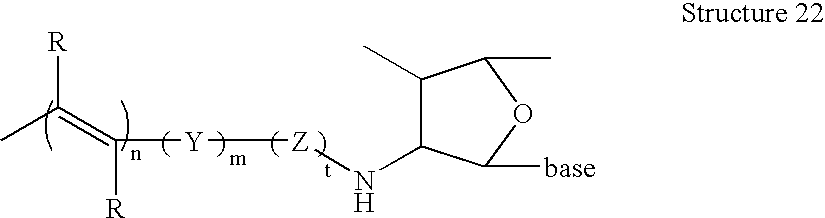
- In Structure 22, Z is as defined above. Suitable linkers include methylene and ethylene.
- In an alternative embodiment, the attachment linker is covalently attached to the nucleic acid via the phosphate of the ribose-phosphate backbone (or analog) of a nucleic acid. In this embodiment, the attachment is direct, utilizes a linker or via an amide bond. Structure 23 depicts a direct linkage, and Structure 24 depicts linkage via an amide bond (both utilize the Structure 3 conductive oligomer, although Structure 8 conductive oligomers and other attachment linkers are also possible). Structures 23 and 24 depict the conductive oligomer in the 3′ position, although the 5′ position is also possible. Furthermore, both Structures 23 and 24 depict naturally occurring phosphodiester bonds, although as those in the art will appreciate, non-standard analogs of phosphodiester bonds may also be used.

- In Structure 23, if the terminal Y is present (i.e. m=1), then preferably Z is not present (i.e. t=0). If the terminal Y is not present, then Z is preferably present.
- Structure 24 depicts a preferred embodiment, wherein the terminal B-D bond is an amide bond, the terminal Y is not present, and Z is a linker, as defined herein.

- In a preferred embodiment, the attachment linker is covalently attached to the nucleic acid via a transition metal ligand. In this embodiment, the attachment linker is covalently attached to a ligand which provides one or more of the coordination atoms for a transition metal. In one embodiment, the ligand to which the attachment linker is attached also has the nucleic acid attached, as is generally depicted below in Structure 25. Alternatively, the attachment linker is attached to one ligand, and the nucleic acid is attached to another ligand, as is generally depicted below in Structure 26 using conductive oligomers as the attachment linker. Thus, in the presence of the transition metal, the attachment linker is covalently attached to the nucleic acid. Both of these structures depict Structure 3 conductive oligomers, although other oligomers may be utilized. Structures 25 and 26 depict two representative structures:

- In the structures depicted herein, M is a metal atom, with transition metals being preferred. Suitable transition metals for use in the invention include, but are not limited to, cadmium (Cd), copper (Cu), cobalt (Co), palladium (Pd), zinc (Zn), iron (Fe), ruthenium (Ru), rhodium (Rh), osmium (Os), rhenium (Re), platinium (Pt), scandium (Sc), titanium (Ti), Vanadium (V), chromium (Cr), manganese (Mn), nickel (Ni), Molybdenum (Mo), technetium (Tc), tungsten (W), and iridium (Ir). That is, the first series of transition metals, the platinum metals (Ru, Rh, Pd, Os, Ir and Pt), along with Fe, Re, W, Mo and Tc, are preferred. Particularly preferred are ruthenium, rhenium, osmium, platinium, cobalt and iron.
- L are the co-ligands, that provide the coordination atoms for the binding of the metal ion. As will be appreciated by those in the art, the number and nature of the co-ligands will depend on the coordination number of the metal ion. Mono-, di- or polydentate co-ligands may be used at any position. Thus, for example, when the metal has a coordination number of six, the L from the terminus of the conductive oligomer, the L, contributed from the nucleic acid, and r, add up to six. Thus, when the metal has a coordination number of six, r may range from zero (when all coordination atoms are provided by the other two ligands) to four, when all the co-ligands are monodentate. Thus generally, r will be from 0 to 8, depending on the coordination number of the metal ion and the choice of the other ligands.
- In one embodiment, the metal ion has a coordination number of six and both the ligand attached to the conductive oligomer and the ligand attached to the nucleic acid are at least bidentate; that is, r is preferably zero, one (i.e. the remaining co-ligand is bidentate) or two (two monodentate co-ligands are used).
- As will be appreciated in the art, the co-ligands can be the same or different. Suitable ligands fall into two categories: ligands which use nitrogen, oxygen, sulfur, carbon or phosphorus atoms (depending on the metal ion) as the coordination atoms (generally referred to in the literature as sigma (a) donors) and organometallic ligands such as metallocene ligands (generally referred to in the literature as pi (n) donors, and depicted herein as L m). Suitable nitrogen donating ligands are well known in the art and include, but are not limited to, NH2; NHR; NRR′; pyridine; pyrazine; isonicotinamide; imidazole; bipyridine and substituted derivatives of bipyridine; terpyridine and substituted derivatives; phenanthrolines, particularly 1,10-phenanthroline (abbreviated phen) and substituted derivatives of phenanthrolines such as 4,7-dimethylphenanthroline and dipyridol[3,2-a:2′,3′-c]phenazine (abbreviated dppz); dipyridophenazine; 1,4,5,8,9,12-hexaazatriphenylene (abbreviated hat); 9,10-phenanthrenequinone diimine (abbreviated phi); 1,4,5,8-tetraazaphenanthrene (abbreviated tap); 1,4,8,11-tetra-azacyclotetradecane (abbreviated cyclam), EDTA, EGTA and isocyanide. Substituted derivatives, including fused derivatives, may also be used. In some embodiments, porphyrins and substituted derivatives of the porphyrin family may be used. See for example, Comprehensive Coordination Chemistry, Ed. Wilkinson et al., Pergammon Press, 1987, Chapters 13.2 (pp73-98), 21.1 (pp.813-898) and 21.3 (pp 915-957), all of which are hereby expressly incorporated by reference.
- Suitable sigma donating ligands using carbon, oxygen, sulfur and phosphorus are known in the art. For example, suitable sigma carbon donors are found in Cotton and Wilkenson, Advanced Organic Chemistry, 5th Edition, John Wiley & Sons, 1988, hereby incorporated by reference; see page 38, for example. Similarly, suitable oxygen ligands include crown ethers, water and others known in the art. Phosphines and substituted phosphines are also suitable; see page 38 of Cotton and Wilkenson.
- The oxygen, sulfur, phosphorus and nitrogen-donating ligands are attached in such a manner as to allow the heteroatoms to serve as coordination atoms.
- In a preferred embodiment, organometallic ligands are used. In addition to purely organic compounds for use as redox moieties, and various transition metal coordination complexes with δ-bonded organic ligand with donor atoms as heterocyclic or exocyclic substituents, there is available a wide variety of transition metal organometallic compounds with n-bonded organic ligands (see Advanced Inorganic Chemistry, 5th Ed., Cotton & Wilkinson, John Wiley & Sons, 1988, chapter 26; Organometallics, A Concise Introduction, Elschenbroich et al., 2nd Ed., 1992, VCH; and Comprehensive Organometallic Chemistry II, A Review of the Literature 1982-1994, Abel et al. Ed., Vol. 7,
chapters 7, 8, 10 & 11, Pergamon Press, hereby expressly incorporated by reference). Such organometallic ligands include cyclic aromatic compounds such as the cyclopentadienide ion [C5H5(−1)] and various ring substituted and ring fused derivatives, such as the indenylide (−1) ion, that yield a class of bis(cyclopentadieyl) metal compounds, (i.e. the metallocenes); see for example Robins et al., J. Am. Chem. Soc. 104:1882-1893 (1982); and Gassman et al., J. Am. Chem. Soc. 108:4228-4229 (1986), incorporated by reference. Of these, ferrocene [(C5H5)2Fe] and its derivatives are prototypical examples which have been used in a wide variety of chemical (Connelly et al., Chem. Rev. 96:877-910 (1996), incorporated by reference) and electrochemical (Geiger et al., Advances in Organometallic Chemistry 23:1-93; and Geiger et al., Advances in Organometallic Chemistry 24:87, incorporated by reference) electron transfer or “redox” reactions. Metallocene derivatives of a variety of the first, second and third row transition metals are potential candidates as redox moieties that are covalently attached to either the ribose ring or the nucleoside base of nucleic acid. Other potentially suitable organometallic ligands include cyclic arenes such as benzene, to yield bis(arene)metal compounds and their ring substituted and ring fused derivatives, of which bis(benzene)chromium is a prototypical example, Other acyclic n-bonded ligands such as the allyl(−1) ion, or butadiene yield potentially suitable organometallic compounds, and all such ligands, in conjuction with other n-bonded and δ-bonded ligands constitute the general class of organometallic compounds in which there is a metal to carbon bond. Electrochemical studies of various dimers and oligomers of such compounds with bridging organic ligands, and additional non-bridging ligands, as well as with and without metal-metal bonds are potential candidate redox moieties in nucleic acid analysis. - When one or more of the co-ligands is an organometallic ligand, the ligand is generally attached via one of the carbon atoms of the organometallic ligand, although attachment may be via other atoms for heterocyclic ligands. Preferred organometallic ligands include metallocene ligands, including substituted derivatives and the metalloceneophanes (see page 1174 of Cotton and Wilkenson, supra). For example, derivatives of metallocene ligands such as methylcyclopentadienyl, with multiple methyl groups being preferred, such as pentamethylcyclopentadienyl, can be used to increase the stability of the metallocene. In a preferred embodiment, only one of the two metallocene ligands of a metallocene are derivatized.
- As described herein, any combination of ligands may be used. Preferred combinations include: a) all ligands are nitrogen donating ligands; b) all ligands are organometallic ligands; and c) the ligand at the terminus of the conductive oligomer is a metallocene ligand and the ligand provided by the nucleic acid is a nitrogen donating ligand, with the other ligands, if needed, are either nitrogen donating ligands or metallocene ligands, or a mixture. These combinations are depicted in representative structures using the conductive oligomer of Structure 3 are depicted in Structures 27 (using phenanthroline and amino as representative ligands), 28 (using ferrocene as the metal-ligand combination) and 29 (using cyclopentadienyl and amino as representative ligands).
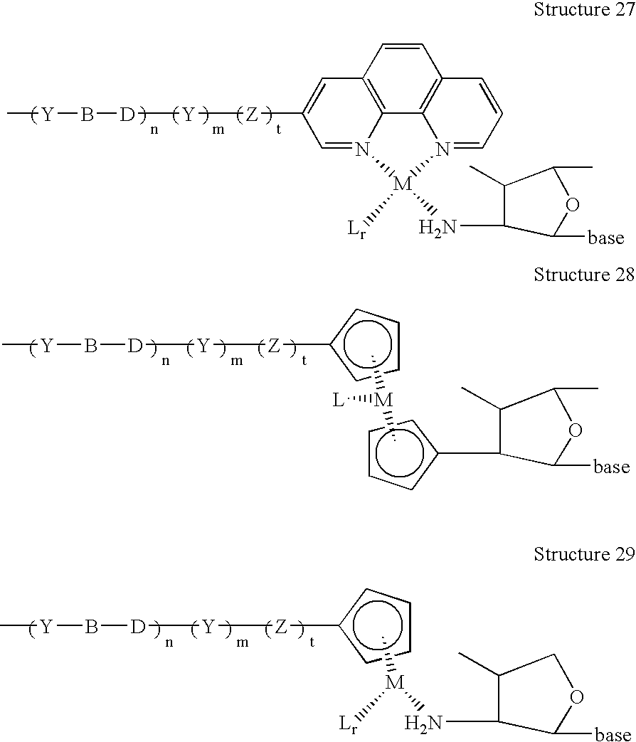
- In a preferred embodiment, the ligands used in the invention show altered fluoroscent properties depending on the redox state of the chelated metal ion. As described below, this thus serves as an additional mode of detection of electron transfer between the ETM and the electrode.
- In addition, similar methods can be used to attach proteins to the biosensor electrode; see for example U.S. Pat. No. 5,620,850, hereby incorporated by reference.
- In a preferred embodiment, as is described more fully below, the ligand attached to the nucleic acid is an amino group attached to the 2′ or 3′ position of a ribose of the ribose-phosphate backbone. This ligand may contain a multiplicity of amino groups so as to form a polydentate ligand which binds the metal ion. Other preferred ligands include cyclopentadiene and phenanthroline.
- The use of metal ions to connect the nucleic acids can serve as an internal control or calibration of the system, to evaluate the number of available nucleic acids on the surface. However, as will be appreciated by those in the art, if metal ions are used to connect the nucleic acids to the attachment linker, it is generally desirable to have this metal ion complex have a different redox potential than that of the ETMs used in the rest of the system, as described below. This is generally true so as to be able to distinguish the presence of the capture probe from the presence of the target sequence. This may be useful for identification, calibration and/or quantification. Thus, the amount of capture probe on an electrode may be compared to the amount of hybridized double stranded nucleic acid to quantify the amount of target sequence in a sample. This is quite significant to serve as an internal control of the sensor or system. This allows a measurement either prior to the addition of target or after, on the same molecules that will be used for detection, rather than rely on a similar but different control system. Thus, the actual molecules that will be used for the detection can be quantified prior to any experiment. This is a significant advantage over prior methods.
- In a preferred embodiment, the capture probe nucleic acids (or other binding ligands) are covalently attached to the electrode via an insulator. The attachment of nucleic acids (and other binding ligands) to insulators such as alkyl groups is well known, and can be done to the base or the backbone, including the ribose or phosphate for backbones containing these moieties, or to alternate backbones for nucleic acid analogs.
- In a preferred embodiment, there may be one or more different capture probe species on the surface. In some embodiments, there may be one type of capture probe, or one type of capture probe extender, as is more fully described below. Alternatively, different capture probes, or one capture probes with a multiplicity of different capture extender probes can be used. Similarly, it may be desirable (particular in the case of nucleic acid analytes and binding ligands in mechanism-2 systems) to use auxiliary capture probes that comprise relatively short probe sequences, that can be used to “tack down” components of the system, for example the recruitment linkers, to increase the concentration of ETMs at the surface.
- Thus the present invention provides tissue collection devices comprising biosensors with substrates comprising at least one electrode comprising monolayers and capture binding ligands, useful in target analyte detection systems of collected samples.
- In a preferred embodiment, the compositions further comprise a solution or soluble binding ligand, although as is more fully described below, for mechanism-1 systems, the ETMs may be added in the form of non-covalently attached hybridization indicators. Solution binding ligands are similar to capture binding ligands, in that they bind, preferably specifically, to target analytes. The solution binding ligand may be the same or different from the capture binding ligand. Generally, the solution binding ligands are not directed attached to the surface, although in some embodiments they may be.
- The solution binding ligand either directly comprises a recruitment linker that comprises at least one ETM or the recruitment linker binds, either directly or indirectly to the solution binding ligand.
- Thus, “solution binding ligands” or “soluble binding ligands” or “signalling ligands” or “signal carriers” or “label probes” or “label binding ligands” with recruitment linkers comprising covalently attached ETMs are provided. That is, one portion of the label probe or solution binding ligand directly or indirectly binds to the target analyte, and one portion comprises a recruitment linker comprising covalently attached ETMs. In some systems, for example in mechanism-1 nucleic acid systems, these may be the same. Similarly, for mechanism-1 systems, the recruitment linker comprises nucleic acid that will hybridize to detection probes.
- The terms “electron donor moiety”, “electron acceptor moiety”, and “ETMs” (ETMs) or grammatical equivalents herein refers to molecules capable of electron transfer under certain conditions. It is to be understood that electron donor and acceptor capabilities are relative; that is, a molecule which can lose an electron under certain experimental conditions will be able to accept an electron under different experimental conditions. It is to be understood that the number of possible electron donor moieties and electron acceptor moieties is very large, and that one skilled in the art of electron transfer compounds will be able to utilize a number of compounds in the present invention. Preferred ETMs include, but are not limited to, transition metal complexes, organic ETMs, and electrodes.
- In a preferred embodiment, the ETMs are transition metal complexes. Transition metals are those whose atoms have a partial or complete d shell of electrons. Suitable transition metals for use in the invention are listed above.
- The transition metals are complexed with a variety of ligands, L, defined above, to form suitable transition metal complexes, as is well known in the art.
- In addition to transition metal complexes, other organic electron donors and acceptors may be covalently attached to the nucleic acid for use in the invention. These organic molecules include, but are not limited to, riboflavin, xanthene dyes, azine dyes, acridine orange, N,N′-dimethyl-2,7-diazapyrenium dichloride (DAP 2+), methylviologen, ethidium bromide, quinones such as N,N′-dimethylanthra(2,1,9-def6,5,10-d′e′f′)diisoquinoline dichloride (ADIQ2+); porphyrins ([meso-tetrakis(N-methyl-x-pyridinium)porphyrin tetrachloride], varlamine blue B hydrochloride, Bindschedler's green; 2,6-dichloroindophenol, 2,6-dibromophenolindophenol; Brilliant crest blue (3-amino-9-dimethyl-amino-10-methylphenoxyazine chloride), methylene blue; Nile blue A (aminoaphthodiethylaminophenoxazine sulfate), indigo-5,5′,7,7′-tetrasulfonic acid, indigo-5,5′,7-trisulfonic acid; phenosafranine, indigo-5-monosulfonic acid; safranine T; bis(dimethylglyoximato)-iron(II) chloride; induline scarlet, neutral red, anthracene, coronene, pyrene, 9-phenylanthracene, rubrene, binaphthyl, DPA, phenothiazene, fluoranthene, phenanthrene, chrysene, 1,8-diphenyl-1,3,5,7-octatetracene, naphthalene, acenaphthalene, perylene, TMPD and analogs and subsitituted derivatives of these compounds.
- In one embodiment, the electron donors and acceptors are redox proteins as are known in the art. However, redox proteins in many embodiments are not preferred.
- The choice of the specific ETMs will be influenced by the type of electron transfer detection used, as is generally outlined below. Preferred ETMs are metallocenes, with ferrocene, including derivatives, being particularly preferred.
- In a preferred embodiment, a plurality of ETMs are used. The use of multiple ETMs provides signal amplification and thus allows more sensitive detection limits. While the use of multiple ETMs on nucleic acids that hybridize to complementary strands can cause decreases in Tms of the hybridization complexes depending on the number, site of attachment and spacing between the multiple ETMs, this is not a factor when the ETMs are on the recruitment linker (i.e. “mechanism-2” systems), since this does not hybridize to a complementary sequence. Accordingly, pluralities of ETMs are preferred, with at least about 2 ETMs per recruitment linker being preferred, and at least about 10 being particularly preferred, and at least about 20 to 50 being especially preferred. In some instances, very large numbers of ETMs (50 to 1000) can be used.
- Thus, solution binding ligands, or label probes, with covalently attached ETMs are provided. The method of attachment of the ETM to the solution binding ligand will vary depending on the mode of detection (i.e. mechanism-1 or -2 systems) and the composition of the solution binding ligand. As is more fully outlined below, in mechanism-2 systems, the portion of the solution binding ligand (or label probe) that comprises the ETM is referred to as a “recruitment linker” and can comprise either nucleic acid or non-nucleic acid. For mechanism-1 systems, the recruitment linker must be nucleic acid.
- Thus, as will be appreciated by those in the art, there are a variety of configurations that can be used. In a preferred embodiment, the recruitment linker is nucleic acid (including analogs), and attachment of the ETMs can be via (1) a base; (2) the backbone, including the ribose, the phosphate, or comparable structures in nucleic acid analogs; (3) nucleoside replacement, described below; or (4) metallocene polymers, as described below. In a preferred embodiment, the recruitment linker is non-nucleic acid, and can be either a metallocene polymer or an alkyl-type polymer (including heteroalkyl, as is more fully described below) containing ETM substitution groups. These options are generally depicted in FIG. 5.
- In a preferred embodiment, the recruitment linker is a nucleic acid, and comprises covalently attached ETMs. The ETMs may be attached to nucleosides within the nucleic acid in a variety of positions. Preferred embodiments include, but are not limited to, (1) attachment to the base of the nucleoside, (2) attachment of the ETM as a base replacement, (3) attachment to the backbone of the nucleic acid, including either to a ribose of the ribose-phosphate backbone or to a phosphate moiety, or to analogous structures in nucleic acid analogs, and (4) attachment via metallocene polymers.
- In addition, as is described below, when the recruitment linker is nucleic acid, it may be desirable to use secondary label probes, that have a first portion that will hybridize to a portion of the primary label probes and a second portion comprising a recruitment linker as is defined herein. This is similar to the use of an arhplifier probe, except that both the primary and the secondary label probes comprise ETMs.
- In a preferred embodiment, the ETM is attached to the base of a nucleoside as is generally outlined above for attachment of the conductive oligomer. Attachment can be to an internal nucleoside or a terminal nucleoside.
- The covalent attachment to the base will depend in part on the ETM chosen, but in general is similar to the attachment of conductive oligomers to bases, as outlined above. Attachment may generally be done to any position of the base. In a preferred embodiment, the ETM is a transition metal complex, and thus attachment of a suitable metal ligand to the base leads to the covalent attachment of the ETM. Alternatively, similar types of linkages may be used for the attachment of organic ETMs, as will be appreciated by those in the art.
- In one embodiment, the C4 attached amino group of cytosine, the C6 attached amino group of adenine, or the C2 attached amino group of guanine may be used as a transition metal ligand.
- Ligands containing aromatic groups can be attached via acetylene linkages as is known in the art (see Comprehensive Organic Synthesis, Trost et al., Ed., Pergamon Press, Chapter 2.4: Coupling Reactions Between sp 2 and sp Carbon Centers, Sonogashira, pp521-549, and pp950-953, hereby incorporated by reference).
Structure 30 depicts a representative structure in the presence of the metal ion and any other necessary ligands;Structure 30 depicts uridine, although as for all the structures herein, any other base may also be used.
- L a is a ligand, which may include nitrogen, oxygen, sulfur or phosphorus donating ligands or organometallic ligands such as metallocene ligands. Suitable La ligands include, but not limited to, phenanthroline, imidazole, bpy and terpy. Lr and M are as defined above. Again, it will be appreciated by those in the art, a linker (“Z”) may be included between the nucleoside and the ETM.
- Similarly, as for the attachment linkers, the linkage may be done using a linker, which may utilize an amide linkage (see generally Telser et al., J. Am. Chem. Soc. 111:7221-7226 (1989); Telser et al., J. Am. Chem. Soc. 111:7226-7232 (1989), both of which are expressly incorporated by reference). These structures are generally depicted below in
Structure 31, which again uses uridine as the base, although as above, the other bases may also be used:
- In this embodiment, L is a ligand as defined above, with L r and M as defined above as well. Preferably, L is amino, phen, byp and terpy.
- In a preferred embodiment, the ETM attached to a nucleoside is a metallocene; i.e. the L and L r of
Structure 31 are both metallocene ligands, Lm, as described above. Structure 32 depicts a preferred embodiment wherein the metallocene is-ferrocene, and the base is uridine, although other bases may be used:
- Preliminary data suggest that Structure 32 may cyclize, with the second acetylene carbon atom attacking the carbonyl oxygen, forming a furan-like structure. Preferred metallocenes include ferrocene, cobaltocene and osmiumocene.
- In a preferred embodiment, the ETM is attached to a ribose at any position of the ribose-phosphate backbone of the nucleic acid, i.e. either the 5′ or 3′ terminus or any internal nucleoside. Ribose in this case can include ribose analogs. As is known in the art, nucleosides that are modified at either the 2′ or 3′ position of the ribose can be made, with nitrogen, oxygen, sulfur and phosphorus-containing modifications possible. Amino-modified and oxygen-modified ribose is preferred. See generally PCT publication WO 95/15971, incorporated herein by reference. These modification groups may be used as a transition metal ligand, or as a chemically functional moiety for attachment of other transition metal ligands and organometallic ligands, or organic electron donor moieties as will be appreciated by those in the art. In this embodiment, a linker such as depicted herein for “Z” may be used as well, or a conductive oligomer between the ribose and the ETM. Preferred embodiments utilize attachment at the 2′ or 3′ position of the ribose, with the 2′ position being preferred. Thus for example, the conductive oligomers depicted in Structure 13, 14 and 15 may be replaced by ETMs; alternatively, the ETMs may be added to the free terminus of the conductive oligomer.
- In a preferred embodiment, a metallocene serves as the ETM, and is attached via an amide bond as depicted below in Structure 33. The examples outline the synthesis of a preferred compound when the metallocene is ferrocene.

- In a preferred embodiment, amine linkages are used, as is generally depicted in Structure 34.

- Z is a linker, as defined herein, with 1-16 atoms being preferred, and 2-4 atoms being particularly preferred, and t is either one or zero.
- In a preferred embodiment, oxo linkages are used, as is generally depicted in
Structure 35.
- In
Structure 35, Z is a linker, as defined herein, and t is either one or zero. Preferred Z linkers include alkyl groups including heteroalkyl groups such as (CH2)n and (CH2CH2O)n, with n from 1 to 10 being preferred, and n=1 to 4 being especially preferred, and n=4 being particularly preferred. - Linkages utilizing other heteroatoms are also possible.
- In a preferred embodiment, an ETM is attached to a phosphate at any position of the ribose-phosphate backbone of the nucleic acid. This may be done in a variety of ways. In one embodiment, phosphodiester bond analogs such as phosphoramide or phosphoramidite linkages may be incorporated into a nucleic acid, where the heteroatom (i.e. nitrogen) serves as a transition metal ligand (see PCT publication WO 95/15971, incorporated by reference). Alternatively, the conductive oligomers depicted in Structures 23 and 24 may be replaced by ETMs. In a preferred embodiment, the composition has the structure shown in Structure 36.

- In Structure 36, the ETM is attached via a phosphate linkage, generally through the use of a linker, Z. Preferred Z linkers include alkyl groups, including heteroalkyl groups such as (CH 2)n, (CH2CH2O)n, with n from 1 to 10 being preferred, and n=1 to 4 being especially preferred, and n=4 being particularly preferred.
- In mechanism-2 systems, when the ETM is attached to the base or the backbone of the nucleoside, it is possible to attach the ETMs via “dendrimer” structures, as is more fully outlined below. Alkyl-based linkers can be used to create multiple branching structures comprising one or more ETMs at the terminus of each branch. Generally, this is done by creating branch points containing multiple hydroxy groups, which optionally can then be used to add additional branch points. The terminal hydroxy groups can then be used in phosphoramidite reactions to add ETMs, as is generally done below for the nucleoside replacement and metallocene polymer reactions.
- In a preferred embodiment, an ETM such as a metallocene is used as a “nucleoside replacement”, serving as an ETM. For example, the distance between the two cyclopentadiene rings of ferrocene is similar to the orthongonal distance between two bases in a double stranded nucleic acid. Other metallocenes in addition to ferrocene may be used, for example, air stable metallocenes such as those containing cobalt or ruthenium. Thus, metallocene moieties may be incorporated into the backbone of a nucleic acid, as is generally depicted in Structure 37 (nucleic acid with a ribose-phosphate backbone) and Structure 38 (peptide nucleic acid backbone). Structures 37 and 38 depict ferrocene, although as will be appreciated by those in the art, other metallocenes may be used as well. In general, air stable metallocenes are preferred, including metallocenes utilizing ruthenium and cobalt as the metal.

- In Structure 37, Z is a linker as defined above, with generally short, alkyl groups, including heteroatoms such as oxygen being preferred. Generally, what is important is the length of the linker, such that minimal perturbations of a double stranded nucleic acid is effected, as is more fully described below. Thus, methylene, ethylene, ethylene glycols, propylene and butylene are all preferred, with ethylene and ethylene glycol being particularly preferred. In addition, each Z linker may be the same or different. Structure 37 depicts a ribose-phosphate backbone, although as will be appreciated by those in the art, nucleic acid analogs may also be used, including ribose analogs and phosphate bond analogs.

- In Structure 38, preferred Z groups are as listed above, and again, each Z linker can be the same or different. As above, other nucleic acid analogs may be used as well.
- In addition, although the structures and discussion above depicts metallocenes, and particularly ferrocene, this same general idea can be used to add ETMs in addition to metallocenes, as nucleoside replacements or in polymer embodiments, described below. Thus, for example, when the ETM is a transition metal complex other than a metallocene, comprising one, two or three (or more) ligands, the ligands can be functionalized as depicted for the ferrocene to allow the addition of phosphoramidite groups. Particularly preferred in this embodiment are complexes comprising at least two ring (for example, aryl and substituted aryl) ligands, where each of the ligands comprises functional groups for attachment via phosphoramidite chemistry. As will be appreciated by those in the art, this type of reaction, creating polymers of ETMs either as a portion of the backbone of the nucleic acid or as “side groups” of the nucleic acids, to allow amplification of the signals generated herein, can be done with virtually any ETM that can be functionalized to contain the correct chemical groups.
- Thus, by inserting a metallocene such as ferrocene (or other ETM) into the backbone of a nucleic acid, nucleic acid analogs are made; that is, the invention provides nucleic adds having a backbone comprising at least one metallocene. This is distinguished from nucleic adds having metallocenes attached to the backbone, i.e. via a ribose, a phosphate, etc. That is, two nucleic acids each made up of a traditional nucleic acid or analog (nucleic acids in this case including a single nucleoside), may be covalently attached to each other via a metallocene. Viewed differently, a metallocene derivative or substituted metallocene is provided, wherein each of the two aromatic rings of the metallocene has a nucleic acid substitutent group.
- In addition, as is more fully outlined below, it is possible to incorporate more than one metallocene into the backbone, either with nucleotides in between and/or with adjacent metallocenes. When adjacent metallocenes are added to the backbone, this is similar to the process described below as “metallocene polymers”; that is, there are areas of metallocene polymers within the backbone.
- In addition to the nucleic acid substitutent groups, it is also desirable in some instances to add additional substituent groups to one or both of the aromatic rings of the metallocene (or ETM). For example, as these nucleoside replacements are generally part of probe sequences to be hybridized with a substantially complementary nucleic acid, for example a target sequence or another probe sequence, it is possible to add substitutent groups to the metallocene rings to facilitate hydrogen bonding to the base or bases on the opposite strand. These may be added to any position on the metallocene rings. Suitable substitutent groups include, but are not limited to, amide groups, amine groups, carboxylic acids, and alcohols, including substituted alcohols. In addition, these substitutent groups can be attached via linkers as well, although in general this is not preferred.
- In addition, substituent groups on an ETM, particularly metallocenes such as ferrocene, may be added to alter the redox properties of the ETM. Thus, for example, in some embodiments, as is more fully described below, it may be desirable to have different ETMs attached in different ways (i.e. base or ribose attachment), on different probes, or for different purposes (for example, calibration or as an internal standard). Thus, the addition of substituent groups on the metallocene may allow two different ETMs to be distinguished.
- In order to generate these metallocene-backbone nucleic acid analogs, the intermediate components are also provided. Thus, in a preferred embodiment, the invention provides phosphoramidite metallocenes, as generally depicted in Structure 39:

- In Structure 39, PG is a protecting group, generally suitable for use in nucleic acid synthesis, with DMT, MMT and TMT all being preferred. The aromatic rings can either be the rings of the metallocene, or aromatic rings of ligands for transition metal complexes or other organic ETMS. The aromatic rings may be the same or different, and may be substituted as discussed herein.
Structure 40 depicts the ferrocene derivative:
- These phosphoramidite analogs can be added to standard oligonucleotide syntheses as is known in the art.
-
Structure 41 depicts the ferrocene peptide nucleic acid (PNA) monomer, that can be added to PNA synthesis as is known in the art:
- In
Structure 41, the PG protecting group is suitable for use in peptide nucleic acid synthesis, with MMT, boc and Fmoc being preferred. - These same intermediate compounds can be used to form ETM or metallocene polymers, which are added to the nucleic acids, rather than as backbone replacements, as is more fully described below.
- In a preferred embodiment, particularly for us in mechanism-2 systems, the ETMs are attached as polymers, for example as metallocene polymers, in a “branched” configuration similar to the “branched DNA” embodiments herein and as outlined in U.S. Pat. No. 5,124,246, using modified functionalized nucleotides. The general idea is as follows. A modified phosphoramidite nucleotide is generated that can ultimately contain a free hydroxy group that can be used in the attachment of phosphoramidite ETMs such as metallocenes. This free hydroxy group could be on the base or the backbone, such as the ribose or the phosphate (although as will be appreciated by those in the art, nucleic acid analogs containing other structures can also be used). The modified nucleotide is incorporated into a nucleic acid, and any hydroxy protecting groups are removed, thus leaving the free hydroxyl. Upon the addition of a phosphoramidite ETM such as a metallocene, as described above in
structures 39 and 40, ETMs, such as metallocene ETMs, are added. Additional phosphoramidite ETMs such as metallocenes can be added, to form “ETM polymers”, including “metallocene polymers” as depicted in FIG. 9 with ferrocene. In addition, in some embodiments, it is desirable to increase the solubility of the polymers by adding a “capping” group to the terminal ETM in the polymer, for example a final phosphate group to the metallocene. Other suitable solubility enhancing “capping” groups will be appreciated by those in the art. It should be noted that these solubility enhancing groups can be added to the polymers in other places, including to the ligand rings, for example on the metallocenes as discussed herein - In a preferred embodiment, the 2′ position of a ribose of a phosphoramidite nucleotide is first functionalized to contain a protected hydroxy group, in this case via an oxo-linkage, although any number of linkers can be used, as is generally described herein for Z linkers. The protected modified nucleotide is then incorporated via standard phosphoramidite chemistry into a growing nucleic acid. The protecting group is removed, and the free hydroxy group is used, again using standard phosphoramidite chemistry to add a phosphoramidite metallocene such as ferrocene. A similar reaction is possible for nucleic acid analogs. For example, using peptide nucleic acids and the metallocene monomer shown in
Structure 41, peptide nucleic acid structures containing metallocene polymers could be generated. - Thus, the present invention provides recruitment linkers of nucleic acids comprising “branches” of metallocene polymers. Preferred embodiments also utilize metallocene polymers from one to about 50 metallocenes in length, with from about 5 to about 20 being preferred and from about 5 to about 10 being especially preferred.
- In addition, when the recruitment linker is nucleic acid, any combination of ETM attachments may be done. In general, as outlined herein, when mechanism-1 systems are used, clusters of nucleosides, containing ETMs can decrease the Tm of hybridization of the probe to its target sequence; thus in general, for mechanism-1 systems, the ETMs are spaced out over the length of the sequence, or only small numbers of them are used.
- In mechanism-1 systems, non-covalently attached ETMs may be used. In one embodiment, the ETM is a hybridization indicator. Hybridization indicators serve as an ETM that will preferentially associate with double stranded nucleic acid is added, usually reversibly, similar to the method of Millan et al., Anal. Chem. 65:2317-2323 (1993); Millian et al., Anal. Chem. 662943-2948 (1994), both of which are hereby expressly incorporated by reference. In this embodiment, increases in the local concentration of ETMs, due to the association of the ETM hybridization indicator with double stranded nucleic acid at the surface, can be monitored using the monolayers comprising the conductive oligomers. Hybridization indicators include intercalators and minor and/or major groove binding moieties. In a preferred embodiment, intercalators may be used; since intercalation generally only occurs in the presence of double stranded nucleic acid, only in the presence of double stranded nucleic acid will the ETMs concentrate. Intercalating transition metal complex ETMs are known in the art. Similarly, major or minor groove binding moieties, such as methylene blue, may also be used in this embodiment.
- In addition, the biosensors of the invention may be used in virtually any method that relies on electrochemical detection of target analytes, with particular utility in nucleic acid detection. For example, the methods and compositions of the invention can be used in nucleic acid detection methods that rely on the detection of ETMs that are inherent to the target analyte. For example, as is generally described in Napier et al., Bioconj. Chem. 8:906 (1997), hereby expressly incorporated by reference, the guanine bases of nucleic acid can be detected via changes in the redox state, i.e. guanine oxidation by ruthenium complexes. Similarly, the methods of the invention find use in detection systems that utilize copper surfaces as catalytic electrodes to oxidize the riboses of nucleic acids.
- In a preferred embodiment, the recruitment linker is not nucleic acid, and instead may be any sort of linker or polymer. As will be appreciated by those in the art, generally any linker or polymer that can be modified to contain ETMs can be used. In-general, the polymers or linkers should be reasonably soluble and contain suitable functional groups for the addition of ETMs.
- As used herein, a “recruitment polymer” comprises at least two or three subunits, which are covalently attached. At least some portion of the monomeric subunits contain functional groups for the covalent attachment of ETMs. In some embodiments coupling moieties are used to covalently link the subunits with the ETMs. Preferred functional groups for attachment are amino groups, carboxy groups, oxo groups and thiol groups, with amino groups being particularly preferred. As will be appreciated by those in the art, a wide variety of recruitment polymers are possible.
- Suitable linkers include, but are not limited to, alkyl linkers (including heteroalkyl (including (poly)ethylene glycol-type structures), substituted alkyl, aryalkyl linkers, etc. As above for the polymers, the linkers will comprise one or more functional groups for the attachment of ETMs, which will be done as will be appreciated by those in the art, for example through the use homo-or hetero-bifunctional linkers as are well known (see 1994 Pierce Chemical Company catalog, technical section on cross-linkers, pages 155-200, incorporated herein by reference).
- Suitable recruitment polymers include, but are not limited to, functionalized styrenes, such as amino styrene, functionalized dextrans, and polyamino acids. Preferred polymers are polyamino acids (both poly-D-amino acids and poly-L-amino acids), such as polylysine, and polymers containing lysine and other amino acids being particularly preferred. As outlined above, in some embodiments, charged recruitment linkers are preferred, for example when non-charged target analytes are to be detected. Other suitable polyamino acids are polyglutamic acid, polyaspartic acid, co-polymers of lysine and glutamic or aspartic acid, co-polymers of lysine with alanine, tyrosine, phenylalanine, serine, tryptophan, and/or proline.
- In a preferred embodiment, the recruitment linker comprises a metallocene polymer, as is described above.
- The attachment of the recruitment linkers to the first portion of the label probe, i.e. the portion that binds either directly or indirectly to the target analyte, will depend on the composition of the recruitment linker, as will be appreciated by those in the art. When the recruitment linker is nucleic acid, it is generally formed during the synthesis of the first portion of the label probe, with incorporation of nucleosides containing ETMs as required. Alternatively, the first portion of the label probe and the recruitment linker may be made separately, and then attached. For example, there may be an overlapping section of complementarity, forming a section of double stranded nucleic acid that can then be chemically crosslinked, for example by using psoralen as is known in the art.
- When non-nucleic acid recruitment linkers are used, attachment of the linker/polymer of the recruitment linker will be done generally using standard chemical techniques, such as will be appreciated by those in the art. For example, when alkyl-based linkers are used, attachment can be similar to the attachment of insulators to nucleic acids.
- In addition, it is possible to have recruitment linkers that are mixtures of-nucleic acids and non-nucleic acids, either in a linear form (i.e. nucleic acid segments linked together with alkyl linkers) or in branched forms (nucleic acids with alkyl “branches” that may contain ETMs and may be additionally branched).
- In a preferred embodiment, for example when the target analyte is a nucleic acid, it is the target sequence itself that carries the ETMs, rather than the recruitment linker of a label probe. For example, as is more fully described below, it is possible to enzymatically add triphosphate nucleotides comprising the ETMs of the invention to a growing nucleic acid, for example during a polymerase chain reaction (PCR). As will be recognized by those in the art, while several enzymes have been shown to generally tolerate modified nucleotides, some of the modified nucleotides of the invention, for example the “nudeoside replacement” embodiments and putatively some of the phosphate attachments, may or may not be recognized by the enzymes to allow incorporation into a growing nucleic acid. Therefore, preferred attachments in this embodiment are to the base or ribose of the nucleotide.
- Thus, for example, PCR amplification of a target sequence, as is well known in the art, will result in target sequences comprising ETMs, generally randomly incorporated into the sequence. The system of the invention can then be configured to allow detection using these ETMs.
- Alternatively, as outlined more fully below, it is possible to enzymatically add nucleotides comprising ETMs to the terminus of a nucleic acid, for example a target nucleic acid. In this embodiment, an effective “recruitment linker” is added to the terminus of the target sequence, that can then be used for detection. Thus the invention provides compositions utilizing electrodes comprising monolayers with capture probes, and target sequences that comprises a first portion that is capable of hybridizing to a component of an assay complex, and a second portion that does not hybridize to a component of an assay complex and comprises at least one covalently attached electron transfer moiety. Similarly, methods utilizing these compositions are also provided.
- It is also possible to have ETMs connected to probe sequences, i.e. sequences designed to hybridize to complementary sequences, i.e. in mechanism-1 sequences, although this may also be used in mechanism-2 systems. Thus, ETMs may be added to non-recruitment linkers as well. For example, there may be ETMs added to sections of label probes that do hybridize to components of the assay complex, for example the first portion, or to the target sequence as outlined above. These ETMs may be used for electron transfer detection in some embodiments, or they may not, depending on the location and system. For example, in some embodiments, when for example the target sequence containing randomly incorporated ETMs is hybridized directly to the capture probe, there may be ETMs in the portion hybridizing to the capture probe. If the capture probe is attached to the electrode using a conductive oligomer, these ETMs can be used to detect electron transfer as has been previously described. Alternatively, these ETMs may not be specifically detected.
- Similarly, in some embodiments, when the recruitment linker is nucleic acid, it may be desirable in some instances to have some or all of the recruitment linker be double stranded, for example in the mechanism-2 systems. In one embodiment, there may be a second recruitment linker, substantially complementary to the first recruitment linker, that can hybridize to the first recruitment linker. In a preferred embodiment, the first recruitment linker comprises the covalently attached ETMs. In an alternative embodiment, the second recruitment linker contains the ETMs, and the first recruitment linker does not, and the ETMs are recruited to the surface by hybridization of the second recruitment linker to the first. In yet another embodiment, both the first and second recruitment linkers comprise ETMs. It should be noted, as discussed above, that nucleic acids comprising a large number of ETMs may not hybridize as well, i.e. the T m may be decreased, depending on the site of attachment and the characteristics of the ETM. Thus, in general, when multiple ETMs are used on hybridizing strands, i.e. in mechanism-1 systems, generally there are less than about 5, with less than about 3 being preferred, or alternatively the ETMs should be spaced sufficiently far apart that the intervening nucleotides can sufficiently hybridize to allow good kinetics.
- For nucleic acid systems, the probes of the present invention are designed to be complementary to a target sequence (either the target sequence of the sample or to other probe sequences, as is described below), such that hybridization of the target sequence and the probes of the present invention occurs. As outlined below, this complementarity need not be perfect; there may be any number of base pair mismatches which will interfere with hybridization between the target sequence and the single stranded nucleic acids of the present invention. However, if the number of mutations is so great that no hybridization can occur under even the least stringent of hybridization conditions, the sequence is not a complementary target sequence. Thus, by “substantially complementary” herein is meant that the probes are sufficiently complementary to the target sequences to hybridize under normal reaction conditions.
- Generally, the nucleic acid compositions of the invention are useful as oligonucleotide probes. As is appreciated by those in the art, the length of the probe will vary with the length of the target sequence and the hybridization and wash conditions. Generally, oligonucleotide probes range from about 8 to about 50 nucleotides, with from about 10 to about 30 being preferred and from about 12 to about 25 being especially preferred. In some cases, very long probes may be used, e.g. 50 to 200-300 nucleotides in length. Thus, in the structures depicted herein, nucleosides may be replaced with nucleic acids.
- A variety of hybridization conditions may be used in the present invention, including high, moderate and low stringency conditions; see for example Maniatis et al., Molecular Cloning: A Laboratory Manual, 2d Edition, 1989, and Short Protocols in Molecular Biology, ed. Ausubel, et al, hereby incorporated by reference. Stringent conditions are sequence-dependent and will be different in different circumstances. Longer sequences hybridize specifically at higher temperatures. An extensive guide to the hybridization of nucleic acids is found in Tijssen, Techniques in Biochemistry and Molecular Biology—Hybridization with Nucleic Acid Probes, “Overview of principles of hybridization and the strategy of nucleic acid assays” (1993). Generally, stringent conditions are selected to be about 5-10 C lower than the thermal melting point (Tm) for the specific sequence at a defined ionic strength pH. The Tm is the temperature (under defined ionic strength, pH and nucleic acid concentration) at which 50% of the probes complementary to the target hybridize to the target sequence at equilibrium (as the target sequences are present in excess, at Tm, 50% of the probes are occupied at equilibrium). Stringent conditions will be those in which the salt concentration is less than about 1.0 sodium ion, typically about 0.01 to 1.0 M sodium ion concentration (or other salts) at pH 7.0 to 8.3 and the temperature is at least about 30 C for short probes (e.g. 10 to 50 nucleotides) and at least about 60 C for long probes (e.g. greater than 50 nucleotides). Stringent conditions may also be achieved with the addition of destabilizing agents such as formamide.
- In another embodiment, less stringent hybridization conditions are used; for example, moderate or low stringency conditions may be used, as are known in the art; see Maniatis and Ausubel, supra, and Tijssen, supra.
- The hybridization conditions may also vary when a non-ionic backbone, i.e. PNA is used, as is known in the art. In addition, cross-linking agents may be added after target binding to cross-link, i.e. covalently attach, the two strands of the hybridization complex.
- As will be appreciated by those in the art, the systems of the invention may take on a large number of different configurations, some of which are depicted in FIGS. 6 and 7. In general, there are three types of systems that can be used: (1) systems in which the target sequence itself is labeled with ETMs (see FIG. 6A; this is generally useful for nucleic acid systems); (2) systems in which label probes directly bind to the target analytes (see FIG. 6C); and (3) systems in which label probes are indirectly bound to the target sequences, for example through the use of amplifier probes (see FIG. 6E).
- In all three of these systems, it is preferred, although not required, that the target sequence be immobilized on the electrode surface. This is preferably done using capture probes and optionally one or more capture extender probes; see FIG. 3 for representative nucleic acid examples. When only capture probes are utilized, it is necessary to have unique capture probes for each target sequence; that is, the surface must be customized to contain unique capture probes. Alternatively, capture extender probes may be used, that allow a “universal” surface, i.e. a surface containing a single type of capture probe that can be used to detect any target sequence. “Capture extender” probes are generally depicted in FIG. 6C and other, and have a first portion that will hybridize to all or part of the capture probe, and a second portion that will hybridize to a portion of the target sequence. This then allows the generation of customized soluble probes, which as will be appreciated by those in the art is generally simpler and less costly. As shown herein, two capture extender probes may be used. This has generally been done to stabilize assay complexes (for example when the target sequence is large, or when large amplifier probes (particularly branched or dendrimer amplifier probes) are used.
- While the discussion and figures herein generally depict nucleic acid embodiments, these same ideas can be used for non-nucleic acid target analytes. For example, capture extender ligands can be generated, as will be appreciated by those in the art. For example, a nucleic acid “tail” can be added to a binding ligand.
- In a preferred embodiment, the binding ligands are added after the formation of the SAM ((4) above). This may be done in a variety of ways, as will be-appreciated by those in the art. In one embodiment, conductive oligomers with terminal functional groups are made, with preferred embodiments utilizing activated carboxylates and isothiocyanates, that will react with primary amines that are either present or put onto the binding ligand such as a nucleic acid, using an activated carboxylate. These two reagents have the advantage of being stable in aqueous solution, yet react with primary alkylamines. However, the primary aromatic amines and secondary and tertiary amines of the bases should not react, thus allowing site specific addition of nucleic acids to the surface. Similar techniques can be used with non-nucleic acid components; for example, as outlined above, the attachment of proteins to SAMs comprising metal chelates is known; see U.S. Pat. No. 5,620,850. This allows the spotting of probes (either capture or detection probes, or both) using known methods (ink jet, spotting, etc.) onto the surface.
- In addition, there are a number of non-nucleic acid methods that can be used to immobilize a nucleic acid on a surface. For example, binding partner pairs can be utilized; i.e. one binding partner is attached to the terminus of the conductive oligomer, and the other to the end of the nucleic acid. This may also be done without using a nucleic acid capture probe; that is, one binding partner serves as the capture probe and the other is attached to either the target sequence or a capture extender probe. That is, either the target sequence comprises the binding partner, or a capture extender probe that will hybridize to the target sequence comprises the binding partner. Suitable binding partner pairs include, but are not limited to, hapten pairs such as biotin/streptavidin; antigens/antibodies; NTA/histidine tags; etc. In general, smaller binding partners are preferred, such that the electrons can pass from the nucleic acid into the conductive oligomer to allow detection.
- In a preferred embodiment, when the target sequence itself is modified to contain a binding partner, the binding partner is attached via a modified nucleotide that can be enzymatically attached to the target sequence, for example during a PCR target amplification step. Alternatively, the binding partner should be easily attached to the target sequence.
- Alternatively, a capture extender probe may be utilized that has a nucleic acid portion for hybridization to the target as well as a binding partner (for example, the capture extender probe may comprise a non-nucleic acid portion such as an alkyl linker that is used to attach a binding partner). In this embodiment, it may be desirable to cross-link the double-stranded nucleic acid of the target and capture extender probe for stability, for example using psoralen as is known in the art.
- In a preferred embodiment, the target sequence itself contains the ETMs. As discussed above, this may be done using target sequences that have ETMs incorporated at any number of positions, as outlined above. In this embodiment, as for the others of the system, the 3′-5′ orientation of the probes and targets is chosen to get the ETM-containing structures (i.e. recruitment linkers or target sequences) as close to the surface of the monolayer as possible, and in the correct orientation. This may be done using attachment via insulators or conductive oligomers as is generally shown in the Figures. In addition, as will be appreciated by those in the art, multiple capture probes can be utilized, either in a configuration such as depicted in FIG. 6D, wherein the 5′-3′ orientation of the capture probes is different, or where “loops” of target form-when multiples of capture probes are used.
- In a preferred embodiment, the label probes directly hybridize to the target sequences, as is generally depicted in the figures. In these embodiments, the target sequence is immobilized on the surface using capture-probes, including capture extender probes. Label probes are then used to bring the ETMs into proximity of the surface of the monolayer. In a preferred embodiment, multiple label probes are used; that is, label probes are designed such that the portion that hybridizes to the target sequence can be different for a number of different label probes, such that amplification of the signal occurs, since multiple label probes can bind for every target sequence. Thus, as depicted in the figures, n is an integer of at least one. Depending on the sensitivity desired, the length of the target sequence, the number of ETMs per label probe, etc., preferred ranges of n are from 1 to 50, with from about 1 to about 20 being particularly preferred, and from about 2 to about 5 being especially preferred. In addition, if “generic” label probes are desired, label extender probes can be used as generally described below for use with amplifier probes.
- As above, generally in this embodiment the configuration of the system and the label probes are designed to recruit the ETMs as close as possible to the monolayer surface.
- In a preferred embodiment, the label probes are hybridized to the target sequence indirectly. That is, the present invention finds use in novel combinations of signal amplification technologies and electron transfer detection on electrodes, which may be particularly useful in sandwich hybridization assays, as generally depicted in the Figures for nucleic acid embodiments; similar systems can be developed for non-nucleic acid target analytes. In these embodiments, the amplifier probes of the invention are bound to the target sequence in a sample either directly or indirectly. Since the amplifier probes preferably contain a relatively large number of amplification sequences that are available for binding of label probes, the detectable signal is significantly increased, and allows the detection limits of the target to be significantly improved. These label and amplifier probes, and the detection methods described herein, may be used in essentially any known nucleic acid hybridization formats, such as those in which the target is bound directly to a solid phase or in sandwich hybridization assays in which the target is bound to one or more nucleic acids that are in turn bound to the solid phase.
- In general, these embodiments may be described as follows with particular reference to nucleic adds. An amplifier probe is hybridized to the target sequence, either directly or through the use of a label extender probe which serves to allow “generic” amplifier probes to be made. The target sequence is preferably, but not required to be, immobilized on the electrode using capture probes. Preferably, the amplifier probe contains a multiplicity of amplification sequences, although in some embodiments, as described below, the amplifier probe may contain only a single amplification sequence. The amplifier probe may take on a number of different forms; either a branched conformation, a dendrimer conformation, or a linear “string” of amplification sequences. These amplification sequences are used to form hybridization complexes with label probes, and the ETMs can be detected using the electrode.
- Accordingly, the present invention provides assay complexes comprising at least one amplifier probe. By “amplifier probe” or “nucleic acid multimer” or “amplification multimer” or grammatical equivalents herein is meant a nucleic acid probe that is used to facilitate signal amplification. Amplifier probes comprise at least a first single-stranded nucleic acid probe sequence, as defined below, and at least one single-stranded nucleic acid amplification sequence, with a multiplicity of amplification sequences being preferred.
- Amplifier probes comprise a first probe sequence that is used, either directly or indirectly, to hybridize to the target sequence. That is, the amplifier probe itself may have a first probe sequence that is substantially complementary to the target sequence or it has a first probe sequence that is substantially complementary to a portion of an additional probe, in this case called a label extender probe, that has a first portion that is substantially complementary to the target sequence. In a preferred embodiment, the first probe sequence-of the amplifier probe is substantially complementary to the target sequence.
- In general, as for all the probes herein, the first probe sequence is of a length sufficient to give specificity and stability. Thus generally, the probe sequences of the invention that are designed to hybridize to another nucleic acid (i.e. probe sequences, amplification sequences, portions or domains of larger probes) are at least about 5 nucleosides long, with at least about 10 being preferred and at least about 15 being especially preferred.
- In a preferred embodiment, the amplifier probes, or any of the other probes of the invention, may form hairpin stem-loop structures in the absence of their target. The length of the stem double-stranded sequence will be selected such that the hairpin structure is not favored in the presence of target. The use of these type of probes, in the systems of the invention or in any nucleic acid detection systems, can result in a significant decrease in non-specific binding and thus an increase in the signal to noise ratio.
- Generally, these hairpin structures comprise four components. The first component is a target binding sequence, i.e. a region complementary to the target (which may be the sample target sequence or another probe sequence to which binding is desired), that is about 10 nucleosides long, with about 15 being preferred. The second component is a loop sequence, that can facilitate the formation of nucleic acid loops. Particularly preferred in this regard are repeats of GTC, which has been identified in Fragile X Syndrome as forming turns. (When PNA analogs are used, turns comprising proline residues may be preferred). Generally, from three to five repeats are used, with four to five being preferred. The third component is a self-complementary region, which has a first portion that is complementary to a portion of the target sequence region and a second portion that comprises a first portion of the label probe binding sequence. The fourth component is substantially complementary to a label probe (or other probe, as the case may be). The fourth component further comprises a “sticky end”, that is, a portion that does not hybridize to any other portion of the probe, and preferably contains most, if not all, of the ETMs. As will be appreciated by those in the art, the any or all of the probes described herein may be configured to form hairpins in the absence of their targets, including the amplifier, capture, capture extender, label and label extender probes.
- In a preferred embodiment, several different amplifier probes are used, each with first probe sequences that will hybridize to a different portion of the target sequence. That is, there is more than one level of amplification; the amplifier probe provides an amplification of signal due to a multiplicity of labelling events, and several different amplifier probes, each with this multiplicity of labels, for each target sequence is used. Thus, preferred embodiments utilize at least two different pools of amplifier probes, each pool having a different probe sequence for hybridization to different portions of the target sequence; the only real limitation on the number of different amplifier probes will be the length of the original target sequence. In addition, it is also possible that the different amplifier probes contain different amplification sequences, although this is generally not preferred.
- In a preferred embodiment, the amplifier probe does not hybridize to the sample target sequence directly, but instead hybridizes to a first portion of a label extender probe. This is particularly useful to allow the use of “generic” amplifier probes, that is, amplifier probes that can be used with a variety of different targets. This may be desirable since several of the amplifier probes require special synthesis techniques. Thus, the addition of a relatively short probe as a label extender probe is preferred. Thus, the first probe sequence of the amplifier probe is substantially complementary to a first portion or domain of a first label extender single-stranded nucleic acid probe. The label extender probe also contains a second portion or domain that is substantially complementary to a portion of the target sequence. Both of these portions are preferably at least about 10 to about 50 nucleotides in length, with a range of about 15 to about 30 being preferred. The terms “first” and “second” are not meant to confer an orientation of the sequences with respect to the 5′-3′ orientation of the target or probe sequences. For example, assuming a 5′-3′ orientation of the complementary target sequence, the first portion may be located either 5′ to the second portion, or 3′ to the second portion. For convenience herein, the order of probe sequences are generally shown from left to right.
- In a preferred embodiment, more than one label extender probe-amplifier probe pair may be used, tht is, n is more than 1. That is, a plurality of label extender probes may be used, each with a portion that is substantially complementary to a different portion of the target sequence; this can serve as another level of amplification. Thus, a preferred embodiment utilizes pools of at least two label extender probes, with the upper limit being set by the length of the target sequence.
- In a preferred embodiment, more than one label extender probe is used with a single amplifier probe to reduce non-specific binding, as is generally outlined in U.S. Pat. No. 5,681,697, incorporated by reference herein. In this embodiment, a first portion of the first label extender probe hybridizes to a first portion of the target sequence, and the second portion of the first label extender probe hybridizes to a first probe sequence of the amplifier probe. A first portion of the second label extender probe hybridizes to a second portion of the target sequence, and the second portion of the second label extender probe hybridizes to a second probe sequence of the amplifier probe. These form structures sometimes referred to as “cruciform” structures or configurations, and are generally done to confer stability when large branched or dendrimeric amplifier probes are used.
- In addition, as will be appreciated by those in the art, the label extender probes may interact with a preamplifier probe, described below, rather than the amplifier probe directly.
- Similarly, as outlined above, a preferred embodiment utilizes several different amplifier probes, each with first probe sequences that will hybridize to a different portion of the label extender probe. In addition, as outlined above, it is also possible that the different amplifier probes contain different amplification sequences, although this is generally not preferred.
- In addition to the first probe sequence, the amplifier probe also comprises at least one amplification sequence. An “amplification sequence” or “amplification segment” or grammatical equivalents herein is meant a sequence that is used, either directly or indirectly, to bind to a first portion of a label probe as is more fully described below. Preferably, the amplifier probe comprises a multiplicity of amplification sequences, with from about 3 to about 1000 being preferred, from about 10 to about 100 being particularly preferred, and about 50 being especially preferred. In some cases, for example when linear amplifier probes are used, from 1 to about 20 is preferred with from about 5 to about 10 being particularly preferred.
- The amplification sequences may be linked to each other in a variety of ways, as will be appreciated by those in the art. They may be covalently linked directly to each other, or to intervening sequences or chemical moieties, through nucleic acid linkages such as phosphodiester bonds, PNA bonds, etc., or through interposed linking agents such amino acid, carbohydrate or polyol bridges, or through other cross-linking agents or binding partners. The site(s) of linkage may be at the ends of a segment, and/or at one or more internal nucleotides in the strand. In a preferred embodiment, the amplification sequences are attached via nucleic acid linkages.
- In a preferred embodiment, branched amplifier probes are used, as are generally described in U.S. Pat. No. 5,124,246, hereby incorporated by reference. Branched amplifier probes may take on “fork-like” or “comb-like” conformations. “Fork-like” branched amplifier probes generally have three or more oligonucleotide segments emanating from a point of origin to form a branched structure. The point of origin may be another nucleotide segment or a multifunctional molecule to whcih at least three segments can be covalently or tightly bound. “Comb-like” branched amplifier probes have a linear backbone with a multiplicity of sidechain oligonucleotides extending from the backbone. In either conformation, the pendant segments will normally depend from a modified nucleotide or other organic moiety having the appropriate functional groups for attachment of oligonudeotides. Furthermore, in either conformation, a large number of amplification sequences are available for binding, either directly or indirectly, to detection probes. In general, these structures are made as is known in the art, using modified multifunctional nucleotides, as is described in U.S. Pat. Nos. 5,635,352 and 5,124,246, among others.
- In a preferred embodiment, dendrimer amplifier probes are used, as are generally described in U.S. Pat. No. 5,175,270, hereby expressly incorporated by reference. Dendrimeric amplifier probes have amplification sequences that are attached via hybridization, and thus have portions of double-stranded nucleic acid as a component of their structure. The outer surface of the dendrimer amplifier probe has a multiplicity of amplification sequences.
- In a preferred embodiment, linear amplifier probes are used, that have individual amplification sequences linked end-to-end either directly or with short intervening sequences to form a polymer. As with the other amplifier configurations, there may be additional sequences or moieties between the amplification sequences.
- In one embodiment, the linear amplifier probe has a single amplification sequence. This may be useful when cycles of hybridization/disassociation occurs, forming a pool of amplifier probe that was hybridized to the target and then removed to allow more probes to bind, or when large numbers of ETMs are used for each label probe. However, in a preferred embodiment, linear amplifier probes comprise a multiplicity of amplification sequences.
- In addition, the amplifier probe may be totally linear, totally branched, totally dendrimeric, or any combination thereof.
- The amplification sequences of the amplifier probe are used, either directly or indirectly, to bind to a label probe to allow detection. In a preferred embodiment, the amplification sequences of the amplifier probe are substantially complementary to a first portion of a label probe. Alternatively, amplifier extender probes are used, that have a first portion that binds to the amplification sequence and a second portion that binds to the first portion of the label probe.
- In addition, the compositions of the invention may include “preamplifier” molecules, which serves a bridging moiety between the label extender molecules and the amplifier probes. In this way, more amplifier and thus more ETMs are ultimately bound to the detection probes. Preamplifier molecules may be either linear or branched, and typically contain in the range of about 30-3000 nucleotides.
- The tissue collection devices of the invention may be used in a variety of ways. Components of the reaction may be added simultaneously, or sequentially, in any order, with preferred embodiments outlined below.
- The invention thus provides assay complexes that generally minimally comprise a target sequence, a capture probe and a label probe (or in the case where the target analyte is labeled with the ETMs, the assay complex comprises a target sequence and a capture probe). “Assay complex” herein is meant the collection of attachment or hybridization complexes comprising analytes, including binding ligands and targets and at least one ETM, that allows detection. The composition of the assay complex depends on the use of the different probe component outlined herein. Thus, in FIG. 6A, the assay complex comprises the capture probe and the target sequence. A preferred embodiment utilizes a capture probe, a target sequence and a label probe. The assay complexes may also include capture extender probes, label extender probes, and amplifier probes, as outlined herein, depending on the configuration used.
- The assays are generally run under stringency conditions which allows formation of the label probe attachment complex only in the presence of target. Stringency can be controlled by altering a step parameter that is a thermodynamic variable, including, but not limited to, temperature, formamide concentration, salt concentration, chaotropic salt concentration pH, organic solvent concentration, etc. Stringency may also include the use of an electrophoretic step to drive non-specific (i.e. low stringency) materials away from the detection electrode.
- These parameters may also be used to control non-specific binding, as is generally outlined in U.S. Pat. No. 5,681,697. Thus it may be desirable to perform certain steps at higher stringency conditions; for example, when an initial hybridization step is done between the target sequence and the label extender and capture extender probes. Running this step at conditions which favor specific binding can allow the reduction of non-specific binding.
- In a preferred nucleic acid embodiment, when all of the components outlined herein are used, a preferred method is as follows. Single-stranded target sequence is incubated under hybridization conditions with the capture extender probes and the label extender probes. A preferred embodiment does this reaction in the presence of the electrode with immobilized capture probes, although this may also be done in two steps, with the initial incubation and the subsequent addition to the electrode. Excess reagents are washed off, and-amplifier probes are then added. If preamplifier probes are used, they may be added either prior to the amplifier probes or simultaneously with the amplifier probes. Excess reagents are washed off, and label probes are then added. Excess reagents are washed off, and detection proceeds as outlined below.
- In one embodiment, a number of capture probes (or capture probes and capture extender probes) that are each substantially complementary to a different portion of the target sequence are used.
- Again, as outlined herein, when amplifier probes are used, the system is generally configured such that upon label probe binding, the recruitment linkers comprising the ETMs are placed in proximity either to the monolayer surface containing conductive oligomers (mechanism-2) or in proximity to detection probes. Thus for example, for mechanism-2 systems, when the ETMs are attached via “dendrimer” type structures as outlined herein, the length of the linkers from the nucleic acid point of attachment to the ETMs may vary, particularly with the length of the capture probe when capture extender probes are used. That is, longer capture probes, with capture extenders, can result in the target sequences being “held” further away from the surface than for shorter capture probes. Adding extra linking sequences between the probe nucleic acid and the ETMs can result in the ETMs being spatially closer to the surface, giving better results. Similarly, for mechanism-1 systems, the length of the recruitment linker, the length of the detection probe, and their distance, may be optimized.
- In addition, if desirable, nucleic acids utilized in the invention may also be ligated together prior to detection, if applicable, by using standard molecular biology techniques such as the use of a ligase. Similarly, if desirable for stability, cross-linking agents may be added to hold the structures stable.
- As will be appreciated by those in the art, while described for nucleic acids, the systems outlined herein can be used for other target analytes as well.
- The compositions of the invention are generally synthesized as outlined below and in U.S. Pat. Nos. 5,591,578; 5,824,473; 5,770,369; 5,705,348; 5,780,234; and 5,952,172; WO98/20162; WO99/37819; PCT US98/12430, PCT US99/01703; PCT US98/12082; PCT/US99/14191; PCT/US99/21683; PCT/US99/25464; PCT US99/10104; and U.S. Ser. Nos. 09/135,183; 09/295,691 and 09/306,653, all of which are expressly incorporated by reference, and utilizing techniques well known in the art. As will be appreciated by those in the art, many of the techniques outlined below are directed to nucleic acids containing a ribose-phosphate backbone. However, as outlined above, many alternate nucleic acid analogs may be utilized, some of which may not contain either ribose or phosphate in the backbone. In these embodiments, for attachment at positions other than the base, attachment is done as will be appreciated by those in the art, depending on the backbone. Thus, for example, attachment can be made at the carbon atoms of the PNA backbone, as is described below, or at either terminus of the PNA. In addition, systems utilizing non-nucleic acid components can be made, as is generally outlined in the references cited above.
- The compositions may be made in several ways and will depend on the components as well as the mechanism used. A preferred method first synthesizes an attachment linker attached to a nucleoside, with addition of additional nucleosides to form the capture probe followed by attachment to the electrode. Alternatively, the whole capture probe may be made and then the completed attachment linker added, followed by attachment to the electrode. Alternatively, a monolayer comprising attachment linkers (some of which have functional groups for attachment of capture probes) is attached to the electrode first, followed by attachment of the capture probe. The latter two methods may be preferred when attachment linkers are used which are not stable in the solvents and under the conditions used in traditional nucleic acid synthesis.
- In a preferred embodiment, the compositions of the invention are made by first forming the attachment linker covalently attached to the nucleoside, followed by the addition of additional nucleosides to form a capture probe nucleic acid, with the last step comprising the addition of the attachment linker to the electrode.
- The attachment of the attachment linker to the nucleoside may be done in several ways. In a preferred embodiment, all or part of the attachment linker is synthesized first (generally with a functional group on the end for attachment to the electrode), which is then attached to the nucleoside. Additional nucleosides are then added as required, with the last step generally being attachment to the electrode. Alternatively, for example when the attachment linker is a conductive oligomer, oligomer units are added one at a time to the nucleoside, with addition of additional nucleosides and attachment to the electrode. A number of representative syntheses are shown in the Figures of WO 98/20162; PCT/US98/12430; PCT/US98/12082; PCT/US99/01705; PCT/US99/01703; and U.S. Ser. Nos. 09/135,183; 60/105,875; and 09/295,691, all of which are incorporated by reference.
- The attachment linker is then attached to a nucleoside that may contain one (or more) of the oligomer units, attached as depicted herein.
- In a preferred embodiment, attachment is to a ribose of the ribose-phosphate backbone, including amide and amine linkages. In a preferred embodiment, there is at least a methylene group or other short aliphatic alkyl groups (as a Z group) between the nitrogen attached to the ribose and the aromatic ring of the conductive oligomer.
- Alternatively, attachment is via a phosphate of the ribose-phosphate backbone, as generally outlined in PCT US97/20014.
- In a preferred embodiment, attachment is via the base. In a preferred embodiment, protecting groups may be added to the base prior to addition of the conductive oligomers, as is generally known in the art. In addition, the palladium cross-coupling reactions may be altered to prevent dimerization problems; i.e. two conductive oligomers dimerizing, rather than coupling to the base.
- Alternatively, attachment to the base may be done by making the nucleoside with one unit of the oligomer, followed by the addition of others.
- Once the modified nucleosides are prepared, protected and activated, prior to attachment to the electrode, they may be incorporated into a growing oligonucleotide by standard synthetic techniques (Gait, Oligonucleotide Synthesis: A Practical Approach, IRL Press, Oxford, UK 1984; Eckstein) in several ways.
- In one embodiment, one or more modified nucleosides are converted to the triphosphate form and incorporated into a growing oligonucleotide chain by using standard molecular biology techniques such as with the use of the enzyme DNA polymerase 1, T4 DNA polymerase, T7 DNA polymerase, Taq DNA polymerase, reverse transcriptase, and RNA polymerases. For the incorporation of a 3′ modified nucleoside to a nucleic acid, terminal deoxynucleotidyltransferase may be used. (Ratliff, Terminal deoxynucleotidyltransferase. In The Enzymes, Vol 14A. P. D. Boyer ed. pp 105-118. Academic Press, San Diego, Calif. 1981). Thus, the present invention provides deoxyribonucleoside triphosphates comprising a covalently attached ETM. Preferred embodiments utilize ETM attachment to the base or the backbone, such as the ribose (preferably in the 2′ position), as is generally depicted below in Structures 42 and 43:

- Thus, in some embodiments, it may be possible to generate the nucleic acids comprising ETMs in situ. For example, a target sequence can hybridize to a capture probe (for example on the surface) in such a way that the terminus of the target sequence is exposed, i.e. unhybridized. The addition of enzyme and triphosphate nucleotides labelled with ETMs allows the in situ creation of the label. Similarly, using labeled nucleotides recognized by polymerases can allow simultaneous PCR and detection; that is, the target sequences are generated in situ.
- In a preferred embodiment, the modified nucleoside is converted to the phosphoramidite or H-phosphonate form, which are then used in solid-phase or solution syntheses of oligonucleotides. In this way the modified nucleoside, either for attachment at the ribose (i.e. amino- or thiol-modified nucleosides) or the base, is incorporated into the oligonucleotide at either an internal position or the 5′ terminus. This is generally done in one of two ways. First, the 5′ position of the ribose is protected with 4′,4-dimethoxytrityl (DMT) followed by reaction with either 2-cyanoethoxy-bis-diisopropylaminophosphine in the presence of diisopropylammonium tetrazolide, or by reaction with
chlorodiisopropylamino 2′-cyanoethyoxyphosphine, to give the phosphoramidite as is known in the art; although other techniques may be used as will be appreciated by those in the art. See Gait, supra; Caruthers, Science 230:281 (1985), both of which are expressly incorporated herein by reference. - For attachment of a group to the 3′ terminus, a preferred method utilizes the attachment of the modified nucleoside (or the nucleoside replacement) to controlled pore glass (CPG) or other oligomeric supports. In this embodiment, the modified nucleoside is protected at the 5′ end with DMT, and then reacted with succinic anhydride with activation. The resulting succinyl compound is attached to CPG or other oligomeric supports as is known in the art. Further phosphoramidite nucleosides are added, either modified or not, to the 5′ end after deprotection. Thus, the present invention provides conductive oligomers or insulators covalently attached to nucleosides attached to solid oligomeric supports such as CPG, and phosphoramidite derivatives of the nucleosides of the invention.
- The invention further provides methods of making label probes with recruitment linkers comprising ETMs. These synthetic reactions will depend on the character of the recruitment linker and the method of attachment of the ETM, as will be appreciated by those in the art. For nucleic acid recruitment linkers, the label probes are generally made as outlined herein with the incorporation of ETMs at one or more positions. When a transition metal complex is used as the ETM, synthesis may occur in several ways. In a preferred embodiment, the ligand(s) are added to a nucleoside, followed by the transition metal ion, and then the nucleoside with the transition metal complex attached is added to an oligonucleotide, i.e. by addition to the nucleic acid synthesizer. Alternatively, the ligand(s) may be attached, followed by incorportation into a growing oligonucleotide chain, followed by the addition of the metal ion.
- In a preferred embodiment, ETMs are attached to a ribose of the ribose-phosphate backbone. This is generally done as is outlined herein for conductive oligomers, as described herein, and in PCT publication WO 95/15971, using amino-modified or oxo-modified nucleosides, at either the 2′ or 3′ position of the ribose. The amino group may then be used either as a ligand, for example as a transition metal ligand for attachment of the metal ion, or as a chemically functional group that can be used for attachment of other ligands or organic ETMs, for example via amide linkages, as will be appreciated by those in the art. For example, the examples describe the synthesis of nucleosides with a variety of ETMs attached via the ribose.
- In a preferred embodiment, ETMs are attached to a phosphate of the ribose-phosphate-backbone. As outlined herein, this may be done using phosphodiester analogs such as phosphoramidite bonds, see generally PCT publication WO 95/15971, or can be done in a similar manner to that described in PCT US97/20014, where the conductive oligomer is replaced by a transition metal ligand or complex or an organic ETM.
- Attachment to alternate backbones, for example peptide nucleic acids or alternate phosphate linkages will be done as will be appreciated by those in the art.
- In a preferred embodiment, ETMs are attached to a base of the nucleoside. This may be done in a variety of ways. In one embodiment, amino groups of the base, either naturally occurring or added as is described herein (see the fiigures, for example), are used either as ligands for transition metal complexes or as a chemically functional group that can be used to add other ligands, for example via an amide linkage, or organic ETMs. This is done as will be appreciated by those in the art. Alternatively, nucleosides containing halogen atoms attached to the heterocyclic ring are commercially available. Acetylene linked ligands may be added using the halogenated bases, as is generally known; see for example, Tzalis et al., Tetrahedron Left. 36(34):6017-6020 (1995); Tzalis et al., Tetrahedron Left. 36(2):3489-3490 (1995); and Tzalis et al., Chem. Communications (in press) 1996, all of which are hereby expressly incorporated by reference. See also the figures and the examples, which describes the synthesis of metallocenes (in this case, ferrocene) attached via acetylene linkages to the bases.
- In one embodiment, the nucleosides are made with transition metal ligands, incorporated into a nucleic acid, and then the transition metal ion and any remaining necessary ligands are added as is known in the art. In an alternative embodiment, the transition metal ion and additional ligands are added prior to incorporation into the nucleic acid.
- Once the nucleic acids of the invention are made, with a covalently attached attachment linker (i.e. either an insulator or a conductive oligomer), the attachment linker is attached to the electrode. The method will vary depending on the type of electrode used. As is described herein, the attachment linkers are generally made with a terminal “A” linker to facilitate attachment to the electrode. For the purposes of this application, a sulfur-gold attachment is considered a covalent attachment.
- In a preferred embodiment, conductive oligomers, insulators, and attachment linkers are covalently attached via sulfur linkages to the electrode. However, surprisingly, traditional protecting groups for use of attaching molecules to gold electrodes are generally not ideal for use in both synthesis of the compositions described herein and inclusion in oligonucleotide synthetic reactions. Accordingly, the present invention provides novel methods for the attachment of conductive oligomers to gold electrodes, utilizing unusual protecting groups, including ethylpyridine, and trimethylsilylethyl as is depicted in the Figures. However, as will be appreciated by those in the art, when the conductive oligomers do not contain nucleic acids, traditional protecting groups such as acetyl groups and others may be used. See Greene et al., supra.
- This may be done in several ways. In a preferred embodiment, the subunit of the conductive oligomer which contains the sulfur atom for attachment to the electrode is protected with an ethyl-pyridine or trimethylsilylethyl group. For the former, this is generally done by contacting the subunit containing the sulfur atom (preferably in the form of a sulfhydryl) with a vinyl pyridine group or vinyl trimethylsilylethyl group under conditions whereby an ethylpyridine group or trimethylsilylethyl group is added to the sulfur atom.
- This subunit also generally contains a functional moiety for attachment of additional subunits, and thus additional subunits are attached to form the conductive oligomer. The conductive oligomer is then attached to a nucleoside, and additional nucleosides attached. The protecting group is then removed and the sulfur-gold covalent attachment is made. Alternatively, all or part of the conductive oligomer is made, and then either a subunit containing a protected sulfur atom is added, or a sulfur atom is added and then protected. The conductive oligomer is then attached to a nucleoside, and additional nucleosides attached. Alternatively, the conductive oligomer attached to a nucleic acid is made, and then either a subunit containing a protected sulfur atom is added, or a sulfur atom is added and then protected. Alternatively, the ethyl pyridine protecting group may be used as above, but removed after one or more steps and replaced with a standard protecting group like a disulfide. Thus, the ethyl pyridine or trimethylsilylethyl group may serve as the protecting group for some of the synthetic reactions, and then removed and replaced with a traditional protecting group.
- By “subunit” of a conductive polymer herein is meant at least the moiety of the conductive oligomer to which the sulfur atom is attached, although additional atoms may be present, including either functional groups which allow the addition of additional components of the conductive oligomer, or additional components of the conductive oligomer. Thus, for example, when Structure 1 oligomers are used, a subunit comprises at least the first Y group.
- A preferred method comprises 1) adding an ethyl pyridine or trimethylsilylethyl protecting group to a sulfur atom attached to a first subunit of a conductive oligomer, generally done by adding a vinyl pyridine or trimethylsilylethyl group to a sulfhydryl; 2) adding additional subunits to form the conductive oligomer; 3) adding at least a first nucleoside to the conductive oligomer; 4) adding additional nucleosides to the first nucleoside to form a nucleic acid; 5) attaching the conductive oligomer to the gold electrode. This may also be done in the absence of nucleosides, as is described in the Examples.
- The above method may also be used to attach insulator molecules to a gold electrode.
- In a preferred embodiment, a monolayer comprising surface species (including conductive oligomers and insulators) is added to the electrode. Generally, the chemistry of addition is similar to or the same as the addition of conductive oligomers to the electrode, i.e. using a sulfur atom for attachment to a gold electrode, etc. Compositions comprising monolayers in addition to the conductive oligomers covalently attached to nucleic acids may be made in at least one of five ways: (1) addition of the monolayer, followed by subsequent addition of the attachment-linker-nucleic acid complex; (2) addition of the attachment linker-nucleic acid complex followed by addition of the monolayer; (3) simultaneous addition of the monolayer and attachment linker-nucleic acid complex; (4) formation of a monolayer (using any of 1, 2 or 3) which includes attachment linkers which terminate in a functional moiety suitable for attachment of a completed nucleic acid; or (5) formation of a monolayer which includes attachment linkers which terminate in a functional moiety suitable for nucleic acid synthesis, i.e. the nucleic acid is synthesized on the surface of the monolayer as is known in the art. Such suitable functional moieties include, but are not limited to, nucleosides, amino groups, carboxyl groups, protected sulfur moieties, or hydroxyl groups for phosphoramidite additions. The examples describe the formation of a monolayer on a gold electrode using the preferred method (1).
- In a preferred embodiment, the nucleic acid is a peptide nucleic acid or analog. In this embodiment, the invention provides peptide nucleic acids with at least one covalently attached ETM or attachment linker. In a preferred embodiment, these moieties are covalently attached to an monomeric subunit of the PNA. By “monomeric subunit of PNA” herein is meant the —NH—CH 2CH2—N(COCH2-Base)-CH2—CO— monomer, or derivatives (herein included within the definition of “nucleoside”) of PNA. For example, the number of carbon atoms in the PNA backbone may be altered; see generally Nielsen et al., Chem. Soc. Rev. 1997 page 73, which discloses a number of PNA derivatives, herein expressly incorporated by reference. Similarly, the amide bond linking the base to the backbone may be altered; phosphoramide and sulfuramide bonds may be used. Alternatively, the moieties are attached to an internal monomeric subunit. By “internal” herein is meant that the monomeric subunit is not either the N-terminal monomeric subunit or the C-terminal monomeric subunit. In this embodiment, the moieties can be attached either to a base or to the backbone of the monomeric subunit. Attachment to the base is done as outlined herein or known in the literature. In general, the moieties are added to a base which is then incorporated into a PNA as outlined herein. The base may be either protected, as required for incorporation into the PNA synthetic reaction, or derivatized, to allow incorporation, either prior to the addition of the chemical substituent or afterwards. Protection and derivatization of the bases is shown in PCT US97/20014. The bases can then be incorporated into monomeric subunits.
- In a preferred embodiment, the moieties are covalently attached to the backbone of the PNA monomer. The attachment is generally to one of the unsubstituted carbon atoms of the monomeric subunit, preferably the α-carbon of the backbone, although attachment at either of the
carbon 1 or 2 positions, or the α-carbon of the amide bond linking the base to the backbone may be done. In the case of PNA analogs, other carbons or atoms may be substituted as well. In a preferred embodiment, moieties are added at the α-carbon atoms, either to a terminal monomeric subunit or an internal one. - In this embodiment, a modified monomeric subunit is synthesized with an ETM or an attachment linker, or a functional group for its attachment, and then the base is added and the modified monomer can be incorporated into a growing PNA chain.
- Once generated, the monomeric subunits with covalently attached moieties are incorporated into a PNA using the techniques outlined in Will et al., Tetrahedron 51(44):12069-12082 (1995), and Vanderlaan et al., Tett. Let. 38:2249-2252 (1997), both of which are hereby expressly incorporated in their entirety. These procedures allow the addition of chemical substituents to peptide nucleic acids without destroying the chemical substituents.
- As will be appreciated by those in the art, electrodes may be made that have any combination of nucleic acids, conductive oligomers and insulators.
- The compositions of the invention may additionally contain, in addition to ETMs, one or more other labels at any position. By “label” herein is meant an element (e.g. an isotope) or chemical compound that is attached to enable the detection of the compound. Preferred labels are radioactive isotopic labels, colored or fluorescent dyes and electrochemical labels such as ETMs. The labels may be incorporated into the compound at any position. In addition, the compositions of the invention may also contain other moieties such as cross-linking agents to facilitate cross-linking of the target-probe complex. See for example, Lukhtanov et al., Nucl. Acids. Res. 24(4):683 (1996) and Tabone et al., Biochem. 33:375 (1994), both of which are expressly incorporated by reference.
- Once made, the compositions find use in a number of applications, as described herein. In particular, the compositions of the invention find use in binding assays for the detection of target analytes, in particular nucleic acid target sequences. As will be appreciated by those in the art, electrodes can be made that have a single species of binding ligand, or multiple binding ligand species, i.e. in an array format.
- In addition, as outlined above, the use of a solid support such as an electrode enables the use of these assays in an array form.
- Once the assay complexes of the invention are made, that generally minimally comprise a capture probe, a target analyte and a label probe, detection proceeds with electronic initiation. Without being limited by the mechanism or theory, detection is based on the transfer of electrons from the ETM to the electrode, including via the “π-way”.
- Detection of electron transfer, i.e. the presence of the ETMs, is generally initiated electronically, with voltage being preferred. A potential is applied to the assay complex. Precise control and variations in the applied potential can be via a potentiostat and either a three electrode system (one reference, one sample (or working) and one counter electrode) or a two electrode system (one sample and one counter electrode). This allows matching of applied potential to peak potential of the system which depends in part on the choice of ETMs and in part on the conductive oligomer used, the composition and integrity of the monolayer, and what type of reference electrode is used. As described herein, ferrocene is a preferred ETM.
- In a preferred embodiment, a co-reductant or co-oxidant (collectively, co-redoxant) is used, as an additional electron source or sink. See generally Sato et al., Bull. Chem. Soc. Jpn 66:1032 (1993); Uosaki et al., Electrochimica Acta 36:1799 (1991); and Alleman et al., J. Phys. Chem 100:17050 (1996); all of which are incorporated by reference.
- In a preferred embodiment, an input electron source in solution is used in the initiation of electron transfer, preferably when initiation and detection are being done using DC current or at AC frequencies where diffusion is not limiting. In general, as will be appreciated by those in the art, preferred embodiments utilize monolayers that contain a minimum of “holes”, such that short-circuiting of the system is avoided. This may be done in several general ways. In a preferred embodiment, an input electron source is used that has a lower or similar redox potential than the ETM of the label probe. Thus, at voltages above the redox potential of the input electron source, both the ETM and the input electron source are oxidized and can thus donate electrons; the ETM donates an electron to the electrode and the input source donates to the ETM. For example, ferrocene, as a ETM attached to the compositions of the invention as described in the examples, has a redox potential of roughly 200 mV in aqueous solution (which can change significantly depending on what the ferrocene is bound to, the manner of the linkage and the presence of any substitution groups). Ferrocyanide, an electron source, has a redox potential of roughly 200 mV as well (in aqueous solution). Accordingly, at or above voltages of roughly 200 mV, ferrocene is converted to ferricenium, which then transfers an electron to the electrode. Now the ferricyanide can be oxidized to transfer an electron to the ETM. In this way, the electron source (or co-reductant) serves to amplify the signal generated in the system, as the electron source molecules rapidly and repeatedly donate electrons to the ETM attached to the nucleic acid. The rate of electron donation or acceptance will be limited by the rate of diffusion of the co-reductant, the electron transfer between the co-reductant and the ETM, which in turn is affected by the concentration and size, etc.
- Alternatively, input electron sources that have lower redox potentials than the ETM are used. At voltages less than the redox potential of the ETM, but higher than the redox potential of the electron source, the input source such as ferrocyanide is unable to be oxided and thus is unable to donate an electron to the ETM; i.e. no electron transfer occurs. Once ferrocene is oxidized, then there is a pathway for electron transfer.
- In an alternate preferred embodiment, an input electron source is used that has a higher redox potential than the ETM of the label probe. For example, luminol, an electron source, has a redox potential of roughly 720 mV. At voltages higher than the redox potential of the ETM, but lower than the redox potential of the electron source, i.e. 200-720 mV, the ferrocene is oxided, and transfers a single electron to the electrode via the conductive oligomer. However, the ETM is unable to accept any electrons from the luminol electron source, since the voltages are less than the redox potential of the luminol. However, at or above the redox potential of luminol, the luminol then transfers an electron to the ETM, allowing rapid and repeated electron transfer. In this way, the electron source (or co-reductant) serves to amplify the signal generated in the system, as the electron source molecules rapidly and repeatedly donate electrons to the ETM of the label probe.
- Luminol has the added benefit of becoming a chemiluminiscent species upon oxidation (see Jirka et al., Analytica Chimica Acta 284:345 (1993)), thus allowing photo-detection of electron transfer from the ETM to the electrode. Thus, as long as the luminol is unable to contact the electrode directly, i.e. in the presence of the SAM such that there is no efficient electron transfer pathway to the electrode, luminol can only be oxidized by transferring an electron to the ETM on the label probe. When the ETM is not present, i.e. when the target sequence is not hybridized to the composition of the invention, luminol is not significantly oxidized, resulting in a low photon emission and thus a low (if any) signal from the luminol. In the presence of the target, a much larger signal is generated. Thus, the measure of luminol oxidation by photon emission is an indirect measurement of the ability of the ETM to donate electrons to the electrode. Furthermore, since photon detection is generally more sensitive than electronic detection, the sensitivity of the system may be increased. Initial results suggest that luminescence may depend on hydrogen peroxide concentration, pH, and luminol concentration, the latter of which appears to be non-linear.
- Suitable electron source molecules are well known in the art, and include, but are not limited to, ferricyanide, and luminol.
- Alternatively, output electron acceptors or sinks could be used, i.e. the above reactions could be run in reverse, with the ETM such as a metallocene receiving an electron from the electrode, converting it to the metallicenium, with the output electron acceptor then accepting the electron rapidly and repeatedly. In this embodiment, cobalticenium is the preferred ETM.
- The presence of the ETMs at the surface of the monolayer can be detected in a variety of ways. A variety of detection methods may be used, including, but not limited to, optical detection (as a result of spectral changes upon changes in redox states), which includes fluorescence, phosphorescence, luminiscence, chemiluminescence, electrochemiluminescence, and refractive index; and electronic detection, including, but not limited to, amperommetry, voltammetry, capacitance and impedence. These methods include time or frequency dependent methods based on AC or DC currents, pulsed methods, lock-in techniques, filtering (high pass, low pass, band pass), and time-resolved techniques including time-resolved fluorescence.
- In one embodiment, the efficient transfer of electrons from the ETM to the electrode results in stereotyped changes in the redox state of the ETM. With many ETMs including the complexes of ruthenium containing bipyridine, pyridine and imidazole rings, these changes in redox state are associated with changes in spectral properties. Significant differences in absorbance are observed between reduced and oxidized states for these molecules. See for example Fabbrizzi et al., Chem. Soc. Rev. 1995 pp197-202). These differences can be monitored using a spectrophotometer or simple photomultiplier tube device.
- In this embodiment, possible electron donors and acceptors include all the derivatives listed above for photoactivation or initiation. Preferred electron donors and acceptors have characteristically large spectral changes upon oxidation and reduction resulting in highly sensitive monitoring of electron transfer. Such examples include Ru(NH 3)4py and Ru(bpy)2im as preferred examples. It should be understood that only the donor or acceptor that is being monitored by absorbance need have ideal spectral characteristics.
- In a preferred embodiment, the electron transfer is detected fluorometrically. Numerous transition metal complexes, including those of ruthenium, have distinct fluorescence properties. Therefore, the change in redox state of the electron donors and electron acceptors attached to the nucleic acid can be monitored very sensitively using fluorescence, for example with Ru(4,7-biphenyl 2-phenanthroline)3 2+. The production of this compound can be easily measured using standard fluorescence assay techniques. For example, laser induced fluorescence can be recorded in a standard single cell fluorimeter, a flow through “on-line” fluorimeter (such as those attached to a chromatography system) or a multi-sample “plate-reader” similar to those marketed for 96-well immuno assays.
- Alternatively, fluorescence can be measured using fiber optic sensors with nucleic acid probes in solution or attached to the fiber optic. Fluorescence is monitored using a photomultiplier tube or other light detection instrument attached to the fiber optic. The advantage of this system is the extremely small volumes of sample that can be assayed.
- In addition, scanning fluorescence detectors such as the Fluorimager sold by Molecular Dynamics are ideally suited to monitoring the fluorescence of modified nucleic acid molecules arrayed on solid surfaces. The advantage of this system is the large number of electron transfer probes that can be scanned at once using chips covered with thousands of distinct nucleic acid probes.
- Many transition metal complexes display fluorescence with large Stokes shifts. Suitable examples include bis- and trisphenanthroline complexes and bis- and trisbipyridyl complexes of transition metals such as ruthenium (see Juris, A., Balzani, V., et. al. Coord. Chem. Rev., V. 84, p. 85-277, 1988). Preferred examples display efficient fluorescence (reasonably high quantum yields) as well as low reorganization energies. These include Ru(4,7-biphenyl 2-phenanthroline)3 2+, Ru(4,4′-diphenyl-2,2′-bipyridine)3 2+ and platinum complexes (see Cummings et al., J. Am. Chem. Soc. 118:1949-1960 (1996), incorporated by reference). Alternatively, a reduction in fluorescence associated with hybridization can be measured using these systems.
- In a further embodiment, electrochemiluminescence is used as the basis of the electron transfer detection. With some ETMs such as Ru 2+(bpy)3, direct luminescence accompanies excited state decay. Changes in this property are associated with nucleic acid hybridization and can be monitored with a simple photomultiplier tube arrangement (see Blackburn, G. F. Clin. Chem. 37: 1534-1539 (1991); and Juris et al., supra.
- In a preferred embodiment, electronic detection is used, including amperommetry, voltammetry, capacitance, and impedence. Suitable techniques include, but are not limited to, electrogravimetry; coulometry (including controlled potential coulometry and constant current coulometry); voltametry (cyclic voltametry, pulse voltametry (normal pulse voltametry, square wave voltametry, differential pulse voltametry, Osteryoung square wave voltametry, and coulostatic pulse techniques); stripping analysis (aniodic stripping analysis, cathiodic stripping analysis, square wave stripping voltammetry); conductance measurements (electrolytic conductance, direct analysis); time-dependent electrochemical analyses (chronoamperometry, chronopotentiometry, cyclic chronopotentiometry and amperometry, AC polography, chronogalvametry, and chronocoulometry); AC impedance measurement; capacitance measurement; AC voltametry; and photoelectrochemistry.
- In a preferred embodiment, monitoring electron transfer is via amperometric detection. This method of detection involves applying a potential (as compared to a separate reference electrode) between the nucleic acid-conjugated electrode and a reference (counter) electrode in the sample containing target genes of interest. Electron transfer of differing efficiencies is induced in samples in the presence or absence of target nucleic acid; that is, the presence or absence of the target nucleic acid, and thus the label probe, can result in different currents.
- The device for measuring electron transfer amperometrically involves sensitive current detection and includes a means of controlling the voltage potential, usually a potentiostat. This voltage is optimized with reference to the potential of the electron donating complex on the label probe. Possible electron donating complexes include those previously mentioned with complexes of iron, osmium, platinum, cobalt, rhenium and ruthenium being preferred and complexes of iron being most preferred.
- In a preferred embodiment, alternative electron detection modes are utilized. For example, potentiometric (or voltammetric) measurements involve non-faradaic (no net current flow) processes and are utilized traditionally in pH and other ion detectors. Similar sensors are used to monitor electron transfer between the ETM and the electrode. In addition, other properties of insulators (such as resistance) and of conductors (such as conductivity, impedance and capicitance) could be used to monitor electron transfer between ETM and the electrode. Finally, any system that generates a current (such as electron transfer) also generates a small magnetic field, which may be monitored in some embodiments.
- It should be understood that one benefit of the fast rates of electron transfer observed in the compositions of the invention is that time resolution can greatly enhance the signal-to-noise results of monitors based on absorbance, fluorescence and electronic current. The fast rates of electron transfer of the present-invention result both in high signals and stereotyped delays between electron transfer initiation and completion. By amplifying signals of particular delays, such as through the use of pulsed initiation of electron transfer and “lock-in” amplifiers of detection, and Fourier transforms.
- In a preferred embodiment, electron transfer is initiated using alternating current (AC) methods. Without being bound by theory, it appears that ETMs, bound to an electrode, generally respond similarly to an AC voltage across a circuit containing resistors and capacitors. Basically, any methods which enable the determination of the nature of these complexes, which act as a resistor and capacitor, can be used as the basis of detection. Surprisingly, traditional electrochemical theory, such as exemplified in Laviron et al., J. Electroanal. Chem. 97:135 (1979) and Laviron et al., J. Electroanal. Chem. 105:35 (1979), both of which are incorporated by reference, do not accurately model the systems described herein, except for very small E AC (less than 10 mV) and relatively large numbers of molecules. That is, the AC current (I) is not accurately described by Laviron's equation. This may be due in part to the fact that this theory assumes an unlimited source and sink of electrons, which is not true in the present systems.
- The AC voltametry theory that models these systems well is outlined in O'Connor et al., J. Electroanal. Chem. 466(2):197-202 (1999), hereby expressly incorporated by reference. The equation that predicts these systems is shown below as Equation 1:


- In Equation 1, n is the number of electrons oxidized or reduced per redox molecule, f is the applied frequency, F is Faraday's constant, N total is the total number of redox molecules, E0 is the formal potential of the redox molecule, R is the gas constant, T is the temperature in degrees Kelvin, and EDC is the electrode potential. The model fits the experimental data very well. In some cases the current is smaller than predicted, however this has been shown to be caused by ferrocene degradation which may be remedied in a number of ways.
- In addition, the faradaic current can also be expressed as a function of time, as shown in Equation 2:

- <|<BOX45>|>| F is the Faradaic current and qe is the elementary charge.
- However, Equation 1 does not incorporate the effect of electron transfer rate nor of instrument factors. Electron transfer rate is important when the rate is close to or lower than the applied frequency. Thus, the true i AC should be a function of all three, as depicted in Equation 3.
- i AC =f(Nernst factors)f(k ET)f(instrument factors)
- These equations can be used to model and predict the expected AC currents in systems which use input signals comprising both AC and DC components. As outlined above, traditional theory surprisingly does not model these systems at all, except for very low voltages.
- In general, non-specifically bound label probes/ETMs show differences in impedance (i.e. higher impedances) than when the label probes containing the ETMs are specifically bound in the correct orientation. In a preferred embodiment, the non-specifically bound material is washed away, resulting in an effective impedance of infinity. Thus, AC detection gives several advantages as is generally discussed below, including an increase in sensitivity, and the ability to “filter out” background noise. In particular, changes in impedance (including, for example, bulk impedance) as between non-specific binding of ETM-containing probes and target-specific assay complex formation may be monitored.
- Accordingly, when using AC initiation and detection methods, the frequency response of the system changes as a result of the presence of the ETM. By “frequency response” herein is meant a modification of signals as a result of electron transfer between the electrode and the ETM. This modification is different depending on signal frequency. A frequency response includes AC currents at one or more frequencies, phase shifts, DC offset voltages, faradaic impedance, etc.
- Once the assay complex including the target sequence and label probe is made, a first input electrical signal is then applied to the system, preferably via at least the sample electrode (containing the complexes of the invention) and the counter electrode, to initiate electron transfer between the electrode and the ETM. Three electrode systems may also be used, with the voltage applied to the reference and working electrodes. The first input signal comprises at least an AC component. The AC component may be of variable amplitude and frequency. Generally, for use in the present methods, the AC amplitude ranges from about 1 mV to about 1.1 V, with from about 10 mV to about 800 mV being preferred, and from about 10 mV to about 500 mV being especially preferred. The AC frequency ranges from about 0.01 Hz to about 100 MHz, with from about 10 Hz to about 10 MHz being preferred, and from about 100 Hz to about 20 MHz being especially preferred.
- The use of combinations of AC and DC signals gives a variety of advantages, including surprising sensitivity and signal maximization.
- In a preferred embodiment, the first input signal comprises a DC component and an AC component. That is, a DC offset voltage between the sample and counter electrodes is swept through the electrochemical potential of the ETM (for example, when ferrocene is used, the sweep is generally from 0 to 500 mV) (or alternatively, the working electrode is grounded and the reference electrode is swept from 0 to −500 mV). The sweep is used to identify the DC voltage at which the maximum response of the system is seen. This is generally at or about the electrochemical potential of the ETM. Once this voltage is determined, either a sweep or one or more uniform DC offset voltages may be used. DC offset voltages of from about −1 V to about +1.1 V are preferred, with from about −500 mV to about +800 mV being especially preferred, and from about −300 mV to about 500 mV being particularly preferred. In a preferred embodiment, the DC offset voltage is not zero. On top of the DC offset voltage, an AC signal component of variable amplitude and frequency is applied. If the ETM is present, and can respond to the AC perturbation, an AC current will be produced due to electron transfer between the electrode and the ETM.
- For defined systems, it may be sufficient to apply a single input signal to differentiate between the presence and absence of the ETM (i.e. the presence of the target sequence) nucleic acid. Alternatively, a plurality of input signals are applied. As outlined herein, this may take a variety of forms, including using multiple frequencies, multiple DC offset voltages, or multiple AC amplitudes, or combinations of any or all of these.
- Thus, in a preferred embodiment, multiple DC offset voltages are used, although as outlined above, DC voltage sweeps are preferred. This may be done at a single frequency, or at two or more frequencies.
- In a preferred embodiment, the AC amplitude is varied. Without being bound by theory, it appears that increasing the amplitude increases the driving force. Thus, higher amplitudes, which result in higher overpotentials give faster rates of electron transfer. Thus, generally, the same system gives an improved response (i.e. higher output signals) at any single frequency through the use of higher overpotentials at that frequency. Thus, the amplitude may be increased at high frequencies to increase the rate of electron transfer through the system, resulting in greater sensitivity. In addition, this may be used, for example, to induce responses in slower systems such as those that do not possess optimal spacing configurations.
- In a preferred embodiment, measurements of the system are taken at at least two separate amplitudes or overpotentials, with measurements at a plurality of amplitudes being preferred. As noted above, changes in response as a result of changes in amplitude may form the basis of identification, calibration and quantification of the system. In addition, one or more AC frequencies can be used as well.
- In a preferred embodiment, the AC frequency is varied. At different frequencies, different molecules respond in different ways. As will be appreciated by those in the art, increasing the frequency generally increases the output current. However, when the frequency is greater than the rate at which electrons may travel between the electrode and the ETM, higher frequencies result in a loss or decrease of output signal. At some point, the frequency will be greater than the rate of electron transfer between the ETM and the electrode, and then the output signal will also drop.
- In one embodiment, detection utilizes a single measurement of output signal at a single frequency. That is, the frequency response of the system in the absence of target sequence, and thus the absence of label probe containing ETMs, can be previously determined to be very low at a particular high frequency. Using this information, any response at a particular frequency, will show the presence of the assay complex. That is, any response at a particular frequency is characteristic of the assay complex. Thus, it may only be necessary to use a single input high frequency, and any changes in frequency response is an indication that the ETM is present, and thus that the target sequence is present.
- In addition, the use of AC techniques allows the significant reduction of background signals at any single frequency due to entities other than the ETMs, i.e. “locking out” or “filtering” unwanted signals. That is, the frequency response of a charge carrier or redox active molecule in solution will be limited by its diffusion coefficient and charge transfer coefficient. Accordingly, at high frequencies, a charge carrier may not diffuse rapidly enough to transfer its charge to the electrode, and/or the charge transfer kinetics may not be fast enough. This is particularly significant in embodiments that do not have good monolayers, i.e. have partial or insufficient monolayers, i.e. where the solvent is accessible to the electrode. As outlined above, in DC techniques, the presence of “holes” where the electrode is accessible to the solvent can result in solvent charge carriers “short circuiting” the system, i.e. the reach the electrode and generate background signal. However, using the present AC techniques, one or more frequencies can be chosen that prevent a frequency response of one or more charge carriers in solution, whether or not a monolayer is present. This is particularly significant since many biological fluids such as blood contain significant amounts of redox active molecules which can interfere with amperometric detection methods.
- In a preferred embodiment, measurements of the system are taken at at least two separate frequencies, with measurements at a plurality of frequencies being preferred. A plurality of frequencies includes a scan. For example, measuring the output signal, e.g., the AC current, at a low input frequency such as 1-20 Hz, and comparing the response to the output signal at high frequency such as 10-100 kHz will show a frequency response difference between the presence and absence of the ETM. In a preferred embodiment, the frequency response is determined at at least two, preferably at least about five, and more preferably at least about ten frequencies.
- After transmitting the input signal to initiate electron transfer, an output signal is received or detected. The presence and magnitude of the output signal will depend on a number of factors, including the overpotential/amplitude of the input signal; the frequency of the input AC signal; the composition of the intervening medium; the DC offset; the environment of the system; the nature of the ETM; the solvent; and the type and concentration of salt. At a given input signal, the presence and magnitude of the output signal will depend in general on the presence or absence of the ETM, the placement and distance of the ETM from the surface of the monolayer and the character of the input signal. In some embodiments, it may be possible to distinguish between non-specific binding of label probes and the formation of target specific assay complexes containing label probes, on the basis of impedance.
- In a preferred embodiment, the output signal comprises an AC current. As outlined above, the magnitude of the output current will depend on a number of parameters. By varying these parameters, the system may be optimized in a number of ways.
- In general, AC currents generated in the present invention range from about 1 femptoamp to about 1 milliamp, with currents from about 50 femptoamps to about 100 microamps being preferred, and from about 1 picoamp to about 1 microamp being especially preferred.
- In a preferred embodiment, the output signal is phase shifted in the AC component relative to the input signal. Without being bound by theory, it appears that the systems of the present invention may be sufficiently uniform to allow phase-shifting based detection. That is, the complex biomolecules of the invention through which electron transfer occurs react to the AC input in a homogeneous manner, similar to standard electronic components, such that a phase shift can be determined. This may serve as the basis of detection between the presence and absence of the ETM, and/or differences between the presence of target-specific assay complexes comprising label probes and non-specific binding of the label probes to the system components.
- The output signal is characteristic of the presence of the ETM; that is, the output signal is characteristic of the presence of the target-specific assay complex comprising label probes and ETMs. In a preferred embodiment, the basis of the detection is a difference in the faradaic impedance of the system as a result of the formation of the assay complex. Faradaic impedance is the impedance of the system between the electrode and the ETM. Faradaic impedance is quite different from the bulk or dielectric impedance, which is the impedance of the bulk solution between the electrodes. Many factors may change the faradaic impedance which may not effect the bulk impedance, and vice versa. Thus, the assay complexes comprising the nucleic adds in this system have a certain faradaic impedance, that will depend on the distance between the ETM and the electrode, their electronic properties, and the composition of the intervening medium, among other things. Of importance in the methods of the invention is that the faradaic impedance between the ETM and the electrode is signficantly different depending on whether the label probes containing the ETMs are specifically or non-specifically bound to the electrode.
- Accordingly, the present invention further provides electronic devices or apparatus for the detection of analytes using the compositions of the invention. The apparatus includes a test chamber for receiving a sample solution which has at least a first measuring or sample electrode, and a second measuring or counter electrode. Three electrode systems are also useful. The first and second measuring electrodes are in contact with a test sample receiving region, such that in the presence of a liquid test sample, the two electrophoresis electrodes may be in electrical contact.
- In a preferred embodiment, the apparatus also includes detection electrodes comprising a single stranded nucleic acid capture probe covalently attached via an attachment linker, and a monolayer comprising conductive oligomers, such as are described herein.
- The apparatus further comprises an AC voltage source electrically connected to the test chamber; that is, to the measuring electrodes. Preferably, the AC voltage source is capable of delivering DC offset voltage as well.
- In a preferred embodiment, the apparatus further comprises a processor capable of comparing the input signal and the output signal. The processor is coupled to the electrodes and configured to receive an output signal, and thus detect the presence of the target nucleic acid.
- Thus, the compositions of the present invention may be used in a variety of research, clinical, quality control, or field testing settings as outlined herein.
- All references cited herein are incorporated by reference in their entirety.
Claims (8)
1. A method of detecting a target analyte in a sample comprising:
a) applying an initiation signal to a tissue collection device comprising an electrode comprising:
I) a self-assembled monolayer;
II) an assay complex comprising:
1) a capture binding ligand;
2) said target analyte; and
3) an electron transfer moiety; and
b) detecting electron transfer between said electrode and said electron transfer moiety.
2. A method according to claim 1 wherein said sample is blood.
3. A method according to claim 1 wherein said self-assembled monolayer comprises insulators.
4. A method according to claim 1 wherein said self-assembled monolayer comprises an EFS.
5. A method according to claim 1 wherein said target analyte is nucleic acid.
6. A method according to claim 1 wherein said capture binding ligand is a capture probe.
7. A method according to claim 1 wherein said assay complex comprises a label probe comprising said electron transfer moiety.
8. A method according to claim 1 wherein said electron transfer moiety is ferrocene.
Priority Applications (1)
| Application Number | Priority Date | Filing Date | Title |
|---|---|---|---|
| US10/697,908 US20040146899A1 (en) | 1998-12-30 | 2003-10-29 | Tissue collection devices containing biosensors |
Applications Claiming Priority (3)
| Application Number | Priority Date | Filing Date | Title |
|---|---|---|---|
| US11417898P | 1998-12-30 | 1998-12-30 | |
| US09/472,657 US6833267B1 (en) | 1998-12-30 | 1999-12-27 | Tissue collection devices containing biosensors |
| US10/697,908 US20040146899A1 (en) | 1998-12-30 | 2003-10-29 | Tissue collection devices containing biosensors |
Related Parent Applications (1)
| Application Number | Title | Priority Date | Filing Date |
|---|---|---|---|
| US09/472,657 Division US6833267B1 (en) | 1998-12-30 | 1999-12-27 | Tissue collection devices containing biosensors |
Publications (1)
| Publication Number | Publication Date |
|---|---|
| US20040146899A1 true US20040146899A1 (en) | 2004-07-29 |
Family
ID=32737871
Family Applications (2)
| Application Number | Title | Priority Date | Filing Date |
|---|---|---|---|
| US09/472,657 Expired - Lifetime US6833267B1 (en) | 1998-12-30 | 1999-12-27 | Tissue collection devices containing biosensors |
| US10/697,908 Abandoned US20040146899A1 (en) | 1998-12-30 | 2003-10-29 | Tissue collection devices containing biosensors |
Family Applications Before (1)
| Application Number | Title | Priority Date | Filing Date |
|---|---|---|---|
| US09/472,657 Expired - Lifetime US6833267B1 (en) | 1998-12-30 | 1999-12-27 | Tissue collection devices containing biosensors |
Country Status (1)
| Country | Link |
|---|---|
| US (2) | US6833267B1 (en) |
Cited By (5)
| Publication number | Priority date | Publication date | Assignee | Title |
|---|---|---|---|---|
| US20030059954A1 (en) * | 2001-09-24 | 2003-03-27 | Inger Vikholm | Method and biosensor for analysis |
| US20030124632A1 (en) * | 2001-12-31 | 2003-07-03 | Vesa Kleimola | Diagnostic methods |
| US20070059732A1 (en) * | 1998-10-27 | 2007-03-15 | Clinical Micro Sensors, Inc. | Detection of target analytes using particles and electrodes |
| US20160022185A1 (en) * | 2013-03-11 | 2016-01-28 | The University Of Toledo | A Biosensor Device to Target Analytes in Situ, in Vivo, and/or in Real Time, and Methods of Making and Using the Same |
| US10509004B2 (en) * | 2011-04-29 | 2019-12-17 | Roche Diabetes Care, Inc. | Sensor elements with a tantalum- or niobium-containing base layer and methods of producing the same |
Families Citing this family (13)
| Publication number | Priority date | Publication date | Assignee | Title |
|---|---|---|---|---|
| FR2932191B1 (en) | 2008-06-05 | 2010-12-03 | Univ Paris Diderot Paris 7 | METHOD FOR ELECTROCHEMICAL IDENTIFICATION OF TARGET SEQUENCES OF NUCLEOTIDES. |
| DE112009003237A5 (en) * | 2008-09-08 | 2012-07-05 | Ogeno Gmbh | BIOPSY INSTRUMENT FOR ENRICHING SAMPLE MATERIAL |
| US20140322706A1 (en) | 2012-10-24 | 2014-10-30 | Jon Faiz Kayyem | Integrated multipelx target analysis |
| JP1628115S (en) | 2012-10-24 | 2019-04-01 | ||
| EP3520895A1 (en) | 2013-03-15 | 2019-08-07 | Genmark Diagnostics Inc. | Fluid container with cantilevered lance |
| USD881409S1 (en) | 2013-10-24 | 2020-04-14 | Genmark Diagnostics, Inc. | Biochip cartridge |
| US9498778B2 (en) | 2014-11-11 | 2016-11-22 | Genmark Diagnostics, Inc. | Instrument for processing cartridge for performing assays in a closed sample preparation and reaction system |
| EP3831481A1 (en) | 2014-11-11 | 2021-06-09 | Genmark Diagnostics Inc. | Instrument and cartridge for performing assays in a closed sample preparation and reaction system |
| US9598722B2 (en) | 2014-11-11 | 2017-03-21 | Genmark Diagnostics, Inc. | Cartridge for performing assays in a closed sample preparation and reaction system |
| US10005080B2 (en) | 2014-11-11 | 2018-06-26 | Genmark Diagnostics, Inc. | Instrument and cartridge for performing assays in a closed sample preparation and reaction system employing electrowetting fluid manipulation |
| CA3036572A1 (en) | 2016-09-19 | 2018-03-22 | Genmark Diagnostics, Inc. | Instrument for processing cartridge for performing assays in a closed sample preparation and reaction system |
| WO2019040769A1 (en) | 2017-08-24 | 2019-02-28 | Clinical Micro Sensors, Inc. (dba GenMark Diagnostics, Inc.) | Electrochemical detection of bacterial and/or fungal infections |
| US20190062809A1 (en) | 2017-08-24 | 2019-02-28 | Clinical Micro Sensors, Inc. (dba GenMark Diagnostics, Inc.) | Electrochemical detection of bacterial and/or fungal infections |
Citations (82)
| Publication number | Priority date | Publication date | Assignee | Title |
|---|---|---|---|---|
| US4704193A (en) * | 1986-05-14 | 1987-11-03 | Gte Laboratories Incorporated | Covalently coupled cofactor modified electrodes and methods of synthesis and use |
| US4707440A (en) * | 1984-01-30 | 1987-11-17 | Enzo Biochem, Inc. | Nucleic acid hybridization assay and detectable molecules useful in such assay |
| US4707352A (en) * | 1984-01-30 | 1987-11-17 | Enzo Biochem, Inc. | Method of radioactively labeling diagnostic and therapeutic agents containing a chelating group |
| US4711955A (en) * | 1981-04-17 | 1987-12-08 | Yale University | Modified nucleotides and methods of preparing and using same |
| US4755458A (en) * | 1984-08-30 | 1988-07-05 | Enzo Biochem, Inc. | Composition and method for the detection of the presence of a polynucleotide sequence of interest |
| US4787963A (en) * | 1987-05-04 | 1988-11-29 | Syntro Corporation | Method and means for annealing complementary nucleic acid molecules at an accelerated rate |
| US4840893A (en) * | 1983-12-16 | 1989-06-20 | Medisense, Inc. | Electrochemical assay for nucleic acids and nucleic acid probes |
| US4849513A (en) * | 1983-12-20 | 1989-07-18 | California Institute Of Technology | Deoxyribonucleoside phosphoramidites in which an aliphatic amino group is attached to the sugar ring and their use for the preparation of oligonucleotides containing aliphatic amino groups |
| US4868103A (en) * | 1986-02-19 | 1989-09-19 | Enzo Biochem, Inc. | Analyte detection by means of energy transfer |
| US4894325A (en) * | 1984-04-27 | 1990-01-16 | Enzo Biochem, Inc. | Hybridization method for the detection of genetic material |
| US4943523A (en) * | 1984-01-30 | 1990-07-24 | Enzo Biochem, Inc. | Detectable molecules, method of preparation and use |
| US4945045A (en) * | 1984-07-06 | 1990-07-31 | Serono Diagnostics Ltd. | Electrochemical methods of assay |
| US4952685A (en) * | 1984-01-30 | 1990-08-28 | Enzo Biochem, Inc. | Detectable molecules, method of preparation and use |
| US4964972A (en) * | 1989-03-30 | 1990-10-23 | Yeda Research And Development Company Limited | Ionic recognition and selective response in self assembling monolayer membranes on electrodes |
| US4994373A (en) * | 1983-01-27 | 1991-02-19 | Enzo Biochem, Inc. | Method and structures employing chemically-labelled polynucleotide probes |
| US5002885A (en) * | 1984-01-30 | 1991-03-26 | Enzo Biochem, Inc. | Detectable molecules, method preparation and use |
| US5013831A (en) * | 1984-01-30 | 1991-05-07 | Enzo Biochem, Inc. | Detectable molecules, method of preparation and use |
| US5082830A (en) * | 1988-02-26 | 1992-01-21 | Enzo Biochem, Inc. | End labeled nucleotide probe |
| US5089112A (en) * | 1989-03-20 | 1992-02-18 | Associated Universities, Inc. | Electrochemical biosensor based on immobilized enzymes and redox polymers |
| US5156810A (en) * | 1989-06-15 | 1992-10-20 | Biocircuits Corporation | Biosensors employing electrical, optical and mechanical signals |
| US5175269A (en) * | 1984-01-30 | 1992-12-29 | Enzo Diagnostics, Inc. | Compound and detectable molecules having an oligo- or polynucleotide with modifiable reactive group |
| US5180968A (en) * | 1991-03-01 | 1993-01-19 | Research Foundation Of State University Of New York | Method and apparatus for compensation of double layer charging current in electrochemical cells |
| US5238808A (en) * | 1984-10-31 | 1993-08-24 | Igen, Inc. | Luminescent metal chelate labels and means for detection |
| US5241060A (en) * | 1982-06-23 | 1993-08-31 | Enzo Diagnostics, Inc. | Base moiety-labeled detectable nucleatide |
| US5242828A (en) * | 1988-11-10 | 1993-09-07 | Pharmacia Biosensor Ab | Sensing surfaces capable of selective biomolecular interactions, to be used in biosensor systems |
| US5278043A (en) * | 1990-01-25 | 1994-01-11 | Hoffmann-La Roche Inc. | Ruthenium-lumazine energy transfer systems |
| US5294369A (en) * | 1990-12-05 | 1994-03-15 | Akzo N.V. | Ligand gold bonding |
| US5312527A (en) * | 1992-10-06 | 1994-05-17 | Concordia University | Voltammetric sequence-selective sensor for target polynucleotide sequences |
| US5354483A (en) * | 1992-10-01 | 1994-10-11 | Andronic Technologies, Inc. | Double-ended tube for separating phases of blood |
| US5356786A (en) * | 1991-03-04 | 1994-10-18 | E. Heller & Company | Interferant eliminating biosensor |
| US5391272A (en) * | 1992-03-06 | 1995-02-21 | Andcare, Inc. | Electrochemical immunoassay methods |
| US5403451A (en) * | 1993-03-05 | 1995-04-04 | Riviello; John M. | Method and apparatus for pulsed electrochemical detection using polymer electroactive electrodes |
| US5443701A (en) * | 1992-08-25 | 1995-08-22 | Yissum Research Development Company Of Hebrew University Of Jerusalem | Electrobiochemical analytical method and electrodes |
| US5552270A (en) * | 1991-03-18 | 1996-09-03 | Institut Molekulyarnoi Biologii Imeni V.A. | Methods of DNA sequencing by hybridization based on optimizing concentration of matrix-bound oligonucleotide and device for carrying out same |
| US5565322A (en) * | 1991-11-07 | 1996-10-15 | Nanogen, Inc. | Hybridization of polynucleotides conjugated with chromophores and fluorophores to generate donor-to donor energy transfer system |
| US5565552A (en) * | 1992-01-21 | 1996-10-15 | Pharmacyclics, Inc. | Method of expanded porphyrin-oligonucleotide conjugate synthesis |
| US5571568A (en) * | 1989-06-15 | 1996-11-05 | Biocircuits Corporation | Multilayered bioelectronic sensors |
| US5573906A (en) * | 1992-03-23 | 1996-11-12 | Hoffmann-La Roche Inc. | Detection of nucleic acids using a hairpin forming oligonucleotide primer and an energy transfer detection system |
| US5591578A (en) * | 1993-12-10 | 1997-01-07 | California Institute Of Technology | Nucleic acid mediated electron transfer |
| US5595908A (en) * | 1985-09-26 | 1997-01-21 | University Of Southern Mississipi | Piezoelectric device for detection of polynucleotide hybridization |
| US5601982A (en) * | 1995-02-07 | 1997-02-11 | Sargent; Jeannine P. | Method and apparatus for determining the sequence of polynucleotides |
| US5603711A (en) * | 1995-01-20 | 1997-02-18 | Everest Medical Corp. | Endoscopic bipolar biopsy forceps |
| US5607646A (en) * | 1992-02-28 | 1997-03-04 | Hitachi, Ltd. | Device for separating polynucleotides having a plurality of electrode-containing cells and movable collecting capillary |
| US5620850A (en) * | 1994-09-26 | 1997-04-15 | President And Fellows Of Harvard College | Molecular recognition at surfaces derivatized with self-assembled monolayers |
| US5632957A (en) * | 1993-11-01 | 1997-05-27 | Nanogen | Molecular biological diagnostic systems including electrodes |
| US5741700A (en) * | 1993-08-11 | 1998-04-21 | University Of Chicago | Method of immobilizing water-soluble bioorganic compounds on a capillary-porous carrier |
| US5756050A (en) * | 1993-08-11 | 1998-05-26 | University Of Chicago | Device of dispensing micro doses of aqueous solutions of substances onto a carrier and device for carrying out said method |
| US5770721A (en) * | 1993-08-11 | 1998-06-23 | University Of Chicago | Method of manufacturing a matrix for the detection of mismatches |
| US5770369A (en) * | 1993-12-10 | 1998-06-23 | California Institute Of Technology | Nucleic acid mediated electron transfer |
| US5776672A (en) * | 1990-09-28 | 1998-07-07 | Kabushiki Kaisha Toshiba | Gene detection method |
| US5795453A (en) * | 1996-01-23 | 1998-08-18 | Gilmartin; Markas A. T. | Electrodes and metallo isoindole ringed compounds |
| US5837859A (en) * | 1993-03-31 | 1998-11-17 | Cis Bio International | Preparation of a electronically conductive polymer/nucleotide copolymer |
| US5871918A (en) * | 1996-06-20 | 1999-02-16 | The University Of North Carolina At Chapel Hill | Electrochemical detection of nucleic acid hybridization |
| US5874046A (en) * | 1996-10-30 | 1999-02-23 | Raytheon Company | Biological warfare agent sensor system employing ruthenium-terminated oligonucleotides complementary to target live agent DNA sequences |
| US5942388A (en) * | 1994-02-22 | 1999-08-24 | Yissum Research Development Company Of The Hebrew University Of Jersaleum | Electrobiochemical method and system for the determination of an analyte which is a member of a recognition pair in a liquid medium, and electrodes thereof |
| US5952172A (en) * | 1993-12-10 | 1999-09-14 | California Institute Of Technology | Nucleic acid mediated electron transfer |
| US5975343A (en) * | 1997-09-12 | 1999-11-02 | Becton Dickinson And Company | Collection container assembly |
| US6020047A (en) * | 1996-09-04 | 2000-02-01 | Kimberly-Clark Worldwide, Inc. | Polymer films having a printed self-assembling monolayer |
| US6060023A (en) * | 1998-03-31 | 2000-05-09 | Motorola, Inc. | Molecular sensing apparatus |
| US6060327A (en) * | 1997-05-14 | 2000-05-09 | Keensense, Inc. | Molecular wire injection sensors |
| US6066448A (en) * | 1995-03-10 | 2000-05-23 | Meso Sclae Technologies, Llc. | Multi-array, multi-specific electrochemiluminescence testing |
| US6071699A (en) * | 1996-06-07 | 2000-06-06 | California Institute Of Technology | Nucleic acid mediated electron transfer |
| US6090933A (en) * | 1996-11-05 | 2000-07-18 | Clinical Micro Sensors, Inc. | Methods of attaching conductive oligomers to electrodes |
| US6096273A (en) * | 1996-11-05 | 2000-08-01 | Clinical Micro Sensors | Electrodes linked via conductive oligomers to nucleic acids |
| US6096825A (en) * | 1994-04-22 | 2000-08-01 | Bio Merieux | Electrically conductive electroactive functionalized conjugated polymers, and uses thereof |
| US6107080A (en) * | 1996-04-25 | 2000-08-22 | Mcgill University | Biosensor device and method |
| US6127127A (en) * | 1995-06-27 | 2000-10-03 | The University Of North Carolina At Chapel Hill | Monolayer and electrode for detecting a label-bearing target and method of use thereof |
| US6140045A (en) * | 1995-03-10 | 2000-10-31 | Meso Scale Technologies | Multi-array, multi-specific electrochemiluminescence testing |
| US6180346B1 (en) * | 1995-06-27 | 2001-01-30 | The Universtiy Of North Carolina At Chapel Hill | Electropolymerizable film, and method of making and use thereof |
| US6203758B1 (en) * | 1997-11-10 | 2001-03-20 | Bio-Pixel Ltd. | Micro-circuit system with array of functionalized micro-electrodes |
| US6207369B1 (en) * | 1995-03-10 | 2001-03-27 | Meso Scale Technologies, Llc | Multi-array, multi-specific electrochemiluminescence testing |
| US6232062B1 (en) * | 1997-03-07 | 2001-05-15 | Clinical Micro Sensors, Inc. | AC methods for the detection of nucleic acids |
| US6264825B1 (en) * | 1998-06-23 | 2001-07-24 | Clinical Micro Sensors, Inc. | Binding acceleration techniques for the detection of analytes |
| US6300141B1 (en) * | 1999-03-02 | 2001-10-09 | Helix Biopharma Corporation | Card-based biosensor device |
| US6306584B1 (en) * | 1997-01-21 | 2001-10-23 | President And Fellows Of Harvard College | Electronic-property probing of biological molecules at surfaces |
| US6403367B1 (en) * | 1994-07-07 | 2002-06-11 | Nanogen, Inc. | Integrated portable biological detection system |
| US6541617B1 (en) * | 1998-10-27 | 2003-04-01 | Clinical Micro Sensors, Inc. | Detection of target analytes using particles and electrodes |
| US6600026B1 (en) * | 1998-05-06 | 2003-07-29 | Clinical Micro Sensors, Inc. | Electronic methods for the detection of analytes utilizing monolayers |
| US6686150B1 (en) * | 1998-01-27 | 2004-02-03 | Clinical Micro Sensors, Inc. | Amplification of nucleic acids with electronic detection |
| US6740518B1 (en) * | 1998-09-17 | 2004-05-25 | Clinical Micro Sensors, Inc. | Signal detection techniques for the detection of analytes |
| US6761716B2 (en) * | 2001-09-18 | 2004-07-13 | Cardiac Pacemakers, Inc. | System and method for assessing electrode-tissue contact and lesion quality during RF ablation by measurement of conduction time |
| US20050003399A1 (en) * | 1998-06-23 | 2005-01-06 | Gary Blackburn | Binding acceleration techniques for the detection of analytes |
Family Cites Families (27)
| Publication number | Priority date | Publication date | Assignee | Title |
|---|---|---|---|---|
| CA1219824A (en) | 1981-04-17 | 1987-03-31 | David C. Ward | Modified nucleotides and methods of preparing and using same |
| US5112974A (en) | 1985-01-18 | 1992-05-12 | The Trustees Of Columbia University In The City Of New York | Mixed ligand complexes and uses thereof as binding agents to DNA |
| CA1273552A (en) | 1985-12-23 | 1990-09-04 | Michael J. Heller | Fluorescent stokes shift probes for polynucleotide hybridization assays |
| JPS63238166A (en) | 1987-03-26 | 1988-10-04 | Mitsubishi Electric Corp | Organic electronic element material |
| US4973789A (en) | 1987-07-30 | 1990-11-27 | The Lubrizol Corporation | Lower alkene polymers |
| DE4039677A1 (en) | 1990-12-12 | 1992-06-17 | Boehringer Mannheim Gmbh | UNIVERSAL BINDING FILM |
| US5849486A (en) | 1993-11-01 | 1998-12-15 | Nanogen, Inc. | Methods for hybridization analysis utilizing electrically controlled hybridization |
| US6051380A (en) | 1993-11-01 | 2000-04-18 | Nanogen, Inc. | Methods and procedures for molecular biological analysis and diagnostics |
| AU658962B2 (en) | 1991-11-15 | 1995-05-04 | Igen, Inc. | Rapid assays for amplification products |
| US5846708A (en) | 1991-11-19 | 1998-12-08 | Massachusetts Institiute Of Technology | Optical and electrical methods and apparatus for molecule detection |
| CA2094785A1 (en) | 1992-05-08 | 1993-11-09 | Jean Gariepy | Metal chelating peptide |
| JPH0641183A (en) | 1992-07-23 | 1994-02-15 | Mitsubishi Kasei Corp | Monomolecular film of oligonucleotide |
| US5472881A (en) | 1992-11-12 | 1995-12-05 | University Of Utah Research Foundation | Thiol labeling of DNA for attachment to gold surfaces |
| ATE319853T1 (en) | 1992-11-27 | 2006-03-15 | Canon Kk | METHOD AND PROBE FOR DETECTING NUCLEIC ACIDS |
| AU7839594A (en) | 1993-09-20 | 1995-04-10 | Regents Of The University Of Colorado, The | Strategy for the production of rna from immobilized templates |
| DE69623494T2 (en) | 1995-06-27 | 2003-04-17 | Univ North Carolina | ELECTROCHEMICAL DETECTION OF NUCLEIC ACID HYBRIDATION |
| US5861247A (en) | 1996-01-26 | 1999-01-19 | University Of Chicago | Rapid method to detect duplex formation in sequencing by hybridization methods |
| US5851772A (en) | 1996-01-29 | 1998-12-22 | University Of Chicago | Microchip method for the enrichment of specific DNA sequences |
| EP2574617B1 (en) | 1996-02-09 | 2016-04-20 | Cornell Research Foundation, Inc. | Detection of nucleic acid sequence differences using the ligase detection reaction with addressable arrays |
| DE69719817T2 (en) | 1996-04-25 | 2003-12-24 | Pence Inc | BIOSENSOR DEVICE AND METHOD |
| WO1997044651A1 (en) | 1996-05-22 | 1997-11-27 | Australian Membrane And Biotechnology Research Institute | Nucleic acid sensor |
| US6001087A (en) | 1996-09-30 | 1999-12-14 | Becton Dickinson And Company | Collection assembly with a reservoir |
| WO1998020162A2 (en) | 1996-11-05 | 1998-05-14 | Clinical Micro Sensors | Electrodes linked via conductive oligomers to nucleic acids |
| US5905024A (en) | 1996-12-17 | 1999-05-18 | University Of Chicago | Method for performing site-specific affinity fractionation for use in DNA sequencing |
| WO1998051823A1 (en) | 1997-05-16 | 1998-11-19 | Mosaic Technologies | Electrophoretic analysis of molecules using immobilized probes |
| WO1998057319A1 (en) | 1997-06-10 | 1998-12-17 | Beaird, Chyle, E. | Multiple access computer monitoring system |
| DE19725190A1 (en) | 1997-06-14 | 1998-12-17 | Innova Gmbh | Devices with integrated electrodes made of electrically conductive plastics |
-
1999
- 1999-12-27 US US09/472,657 patent/US6833267B1/en not_active Expired - Lifetime
-
2003
- 2003-10-29 US US10/697,908 patent/US20040146899A1/en not_active Abandoned
Patent Citations (99)
| Publication number | Priority date | Publication date | Assignee | Title |
|---|---|---|---|---|
| US5328824A (en) * | 1981-04-17 | 1994-07-12 | Yale University | Methods of using labeled nucleotides |
| US5449767A (en) * | 1981-04-17 | 1995-09-12 | Yale University | Modified polynucleotides and methods of preparing same |
| US4711955A (en) * | 1981-04-17 | 1987-12-08 | Yale University | Modified nucleotides and methods of preparing and using same |
| US5241060A (en) * | 1982-06-23 | 1993-08-31 | Enzo Diagnostics, Inc. | Base moiety-labeled detectable nucleatide |
| US4994373A (en) * | 1983-01-27 | 1991-02-19 | Enzo Biochem, Inc. | Method and structures employing chemically-labelled polynucleotide probes |
| US4840893A (en) * | 1983-12-16 | 1989-06-20 | Medisense, Inc. | Electrochemical assay for nucleic acids and nucleic acid probes |
| US4849513A (en) * | 1983-12-20 | 1989-07-18 | California Institute Of Technology | Deoxyribonucleoside phosphoramidites in which an aliphatic amino group is attached to the sugar ring and their use for the preparation of oligonucleotides containing aliphatic amino groups |
| US5002885A (en) * | 1984-01-30 | 1991-03-26 | Enzo Biochem, Inc. | Detectable molecules, method preparation and use |
| US4707440A (en) * | 1984-01-30 | 1987-11-17 | Enzo Biochem, Inc. | Nucleic acid hybridization assay and detectable molecules useful in such assay |
| US4943523A (en) * | 1984-01-30 | 1990-07-24 | Enzo Biochem, Inc. | Detectable molecules, method of preparation and use |
| US4952685A (en) * | 1984-01-30 | 1990-08-28 | Enzo Biochem, Inc. | Detectable molecules, method of preparation and use |
| US5175269A (en) * | 1984-01-30 | 1992-12-29 | Enzo Diagnostics, Inc. | Compound and detectable molecules having an oligo- or polynucleotide with modifiable reactive group |
| US4707352A (en) * | 1984-01-30 | 1987-11-17 | Enzo Biochem, Inc. | Method of radioactively labeling diagnostic and therapeutic agents containing a chelating group |
| US5013831A (en) * | 1984-01-30 | 1991-05-07 | Enzo Biochem, Inc. | Detectable molecules, method of preparation and use |
| US4894325A (en) * | 1984-04-27 | 1990-01-16 | Enzo Biochem, Inc. | Hybridization method for the detection of genetic material |
| US4945045A (en) * | 1984-07-06 | 1990-07-31 | Serono Diagnostics Ltd. | Electrochemical methods of assay |
| US4755458A (en) * | 1984-08-30 | 1988-07-05 | Enzo Biochem, Inc. | Composition and method for the detection of the presence of a polynucleotide sequence of interest |
| US5238808A (en) * | 1984-10-31 | 1993-08-24 | Igen, Inc. | Luminescent metal chelate labels and means for detection |
| US5595908A (en) * | 1985-09-26 | 1997-01-21 | University Of Southern Mississipi | Piezoelectric device for detection of polynucleotide hybridization |
| US4868103A (en) * | 1986-02-19 | 1989-09-19 | Enzo Biochem, Inc. | Analyte detection by means of energy transfer |
| US4704193A (en) * | 1986-05-14 | 1987-11-03 | Gte Laboratories Incorporated | Covalently coupled cofactor modified electrodes and methods of synthesis and use |
| US4787963A (en) * | 1987-05-04 | 1988-11-29 | Syntro Corporation | Method and means for annealing complementary nucleic acid molecules at an accelerated rate |
| US5082830A (en) * | 1988-02-26 | 1992-01-21 | Enzo Biochem, Inc. | End labeled nucleotide probe |
| US5242828A (en) * | 1988-11-10 | 1993-09-07 | Pharmacia Biosensor Ab | Sensing surfaces capable of selective biomolecular interactions, to be used in biosensor systems |
| US5436161A (en) * | 1988-11-10 | 1995-07-25 | Pharmacia Biosensor Ab | Matrix coating for sensing surfaces capable of selective biomolecular interactions, to be used in biosensor systems |
| US5089112A (en) * | 1989-03-20 | 1992-02-18 | Associated Universities, Inc. | Electrochemical biosensor based on immobilized enzymes and redox polymers |
| US4964972A (en) * | 1989-03-30 | 1990-10-23 | Yeda Research And Development Company Limited | Ionic recognition and selective response in self assembling monolayer membranes on electrodes |
| US5571568A (en) * | 1989-06-15 | 1996-11-05 | Biocircuits Corporation | Multilayered bioelectronic sensors |
| US5156810A (en) * | 1989-06-15 | 1992-10-20 | Biocircuits Corporation | Biosensors employing electrical, optical and mechanical signals |
| US5278043A (en) * | 1990-01-25 | 1994-01-11 | Hoffmann-La Roche Inc. | Ruthenium-lumazine energy transfer systems |
| US5776672A (en) * | 1990-09-28 | 1998-07-07 | Kabushiki Kaisha Toshiba | Gene detection method |
| US5294369A (en) * | 1990-12-05 | 1994-03-15 | Akzo N.V. | Ligand gold bonding |
| US5180968A (en) * | 1991-03-01 | 1993-01-19 | Research Foundation Of State University Of New York | Method and apparatus for compensation of double layer charging current in electrochemical cells |
| US5356786A (en) * | 1991-03-04 | 1994-10-18 | E. Heller & Company | Interferant eliminating biosensor |
| US5552270A (en) * | 1991-03-18 | 1996-09-03 | Institut Molekulyarnoi Biologii Imeni V.A. | Methods of DNA sequencing by hybridization based on optimizing concentration of matrix-bound oligonucleotide and device for carrying out same |
| US5565322A (en) * | 1991-11-07 | 1996-10-15 | Nanogen, Inc. | Hybridization of polynucleotides conjugated with chromophores and fluorophores to generate donor-to donor energy transfer system |
| US5565552A (en) * | 1992-01-21 | 1996-10-15 | Pharmacyclics, Inc. | Method of expanded porphyrin-oligonucleotide conjugate synthesis |
| US5607646A (en) * | 1992-02-28 | 1997-03-04 | Hitachi, Ltd. | Device for separating polynucleotides having a plurality of electrode-containing cells and movable collecting capillary |
| US5391272A (en) * | 1992-03-06 | 1995-02-21 | Andcare, Inc. | Electrochemical immunoassay methods |
| US5573906A (en) * | 1992-03-23 | 1996-11-12 | Hoffmann-La Roche Inc. | Detection of nucleic acids using a hairpin forming oligonucleotide primer and an energy transfer detection system |
| US5443701A (en) * | 1992-08-25 | 1995-08-22 | Yissum Research Development Company Of Hebrew University Of Jerusalem | Electrobiochemical analytical method and electrodes |
| US5354483A (en) * | 1992-10-01 | 1994-10-11 | Andronic Technologies, Inc. | Double-ended tube for separating phases of blood |
| US5312527A (en) * | 1992-10-06 | 1994-05-17 | Concordia University | Voltammetric sequence-selective sensor for target polynucleotide sequences |
| US5403451A (en) * | 1993-03-05 | 1995-04-04 | Riviello; John M. | Method and apparatus for pulsed electrochemical detection using polymer electroactive electrodes |
| US5837859A (en) * | 1993-03-31 | 1998-11-17 | Cis Bio International | Preparation of a electronically conductive polymer/nucleotide copolymer |
| US5741700A (en) * | 1993-08-11 | 1998-04-21 | University Of Chicago | Method of immobilizing water-soluble bioorganic compounds on a capillary-porous carrier |
| US5770721A (en) * | 1993-08-11 | 1998-06-23 | University Of Chicago | Method of manufacturing a matrix for the detection of mismatches |
| US5756050A (en) * | 1993-08-11 | 1998-05-26 | University Of Chicago | Device of dispensing micro doses of aqueous solutions of substances onto a carrier and device for carrying out said method |
| US5632957A (en) * | 1993-11-01 | 1997-05-27 | Nanogen | Molecular biological diagnostic systems including electrodes |
| US6177250B1 (en) * | 1993-12-10 | 2001-01-23 | California Institute Of Technology | Nucleic acid mediated electron transfer |
| US5770369A (en) * | 1993-12-10 | 1998-06-23 | California Institute Of Technology | Nucleic acid mediated electron transfer |
| US6087100A (en) * | 1993-12-10 | 2000-07-11 | California Institute Of Technology | Nucleic acid mediated electron transfer |
| US5952172A (en) * | 1993-12-10 | 1999-09-14 | California Institute Of Technology | Nucleic acid mediated electron transfer |
| US5705348A (en) * | 1993-12-10 | 1998-01-06 | California Institute Of Technology | Nucleic acid mediated electron transfer |
| US5780234A (en) * | 1993-12-10 | 1998-07-14 | California Institute Of Technology | Nucleic acid mediated electron transfer |
| US6180352B1 (en) * | 1993-12-10 | 2001-01-30 | California Insitute Of Technology | Nucleic acid mediated electron transfer |
| US5824473A (en) * | 1993-12-10 | 1998-10-20 | California Institute Of Technology | Nucleic acid mediated electron transfer |
| US5591578A (en) * | 1993-12-10 | 1997-01-07 | California Institute Of Technology | Nucleic acid mediated electron transfer |
| US6238870B1 (en) * | 1993-12-10 | 2001-05-29 | California Institute Of Technology | Nucleic acid mediated electron transfer |
| US6200761B1 (en) * | 1993-12-10 | 2001-03-13 | California Institute Of Technology | Nucleic acid mediated electron transfer |
| US5942388A (en) * | 1994-02-22 | 1999-08-24 | Yissum Research Development Company Of The Hebrew University Of Jersaleum | Electrobiochemical method and system for the determination of an analyte which is a member of a recognition pair in a liquid medium, and electrodes thereof |
| US6096825A (en) * | 1994-04-22 | 2000-08-01 | Bio Merieux | Electrically conductive electroactive functionalized conjugated polymers, and uses thereof |
| US6403367B1 (en) * | 1994-07-07 | 2002-06-11 | Nanogen, Inc. | Integrated portable biological detection system |
| US5620850A (en) * | 1994-09-26 | 1997-04-15 | President And Fellows Of Harvard College | Molecular recognition at surfaces derivatized with self-assembled monolayers |
| US5603711A (en) * | 1995-01-20 | 1997-02-18 | Everest Medical Corp. | Endoscopic bipolar biopsy forceps |
| US5601982A (en) * | 1995-02-07 | 1997-02-11 | Sargent; Jeannine P. | Method and apparatus for determining the sequence of polynucleotides |
| US6066448A (en) * | 1995-03-10 | 2000-05-23 | Meso Sclae Technologies, Llc. | Multi-array, multi-specific electrochemiluminescence testing |
| US6140045A (en) * | 1995-03-10 | 2000-10-31 | Meso Scale Technologies | Multi-array, multi-specific electrochemiluminescence testing |
| US6090545A (en) * | 1995-03-10 | 2000-07-18 | Meso Scale Technologies, Llc. | Multi-array, multi-specific electrochemiluminescence testing |
| US6207369B1 (en) * | 1995-03-10 | 2001-03-27 | Meso Scale Technologies, Llc | Multi-array, multi-specific electrochemiluminescence testing |
| US6127127A (en) * | 1995-06-27 | 2000-10-03 | The University Of North Carolina At Chapel Hill | Monolayer and electrode for detecting a label-bearing target and method of use thereof |
| US6180346B1 (en) * | 1995-06-27 | 2001-01-30 | The Universtiy Of North Carolina At Chapel Hill | Electropolymerizable film, and method of making and use thereof |
| US5795453A (en) * | 1996-01-23 | 1998-08-18 | Gilmartin; Markas A. T. | Electrodes and metallo isoindole ringed compounds |
| US6107080A (en) * | 1996-04-25 | 2000-08-22 | Mcgill University | Biosensor device and method |
| US6071699A (en) * | 1996-06-07 | 2000-06-06 | California Institute Of Technology | Nucleic acid mediated electron transfer |
| US5871918A (en) * | 1996-06-20 | 1999-02-16 | The University Of North Carolina At Chapel Hill | Electrochemical detection of nucleic acid hybridization |
| US6020047A (en) * | 1996-09-04 | 2000-02-01 | Kimberly-Clark Worldwide, Inc. | Polymer films having a printed self-assembling monolayer |
| US5874046A (en) * | 1996-10-30 | 1999-02-23 | Raytheon Company | Biological warfare agent sensor system employing ruthenium-terminated oligonucleotides complementary to target live agent DNA sequences |
| US6479240B1 (en) * | 1996-11-05 | 2002-11-12 | Clinical Micro Sensors, Inc. | Electrodes linked via conductive oligomers to nucleic acids |
| US20030003473A1 (en) * | 1996-11-05 | 2003-01-02 | Clinical Micro Sensors, Inc. | Electrodes linked via conductive oligomers to nucleic acids |
| US20030148328A1 (en) * | 1996-11-05 | 2003-08-07 | Kayyem Jon Faiz | AC methods for the detection of nucleic acids |
| US6221583B1 (en) * | 1996-11-05 | 2001-04-24 | Clinical Micro Sensors, Inc. | Methods of detecting nucleic acids using electrodes |
| US6090933A (en) * | 1996-11-05 | 2000-07-18 | Clinical Micro Sensors, Inc. | Methods of attaching conductive oligomers to electrodes |
| US6096273A (en) * | 1996-11-05 | 2000-08-01 | Clinical Micro Sensors | Electrodes linked via conductive oligomers to nucleic acids |
| US6306584B1 (en) * | 1997-01-21 | 2001-10-23 | President And Fellows Of Harvard College | Electronic-property probing of biological molecules at surfaces |
| US6232062B1 (en) * | 1997-03-07 | 2001-05-15 | Clinical Micro Sensors, Inc. | AC methods for the detection of nucleic acids |
| US6060327A (en) * | 1997-05-14 | 2000-05-09 | Keensense, Inc. | Molecular wire injection sensors |
| US5975343A (en) * | 1997-09-12 | 1999-11-02 | Becton Dickinson And Company | Collection container assembly |
| US6203758B1 (en) * | 1997-11-10 | 2001-03-20 | Bio-Pixel Ltd. | Micro-circuit system with array of functionalized micro-electrodes |
| US6686150B1 (en) * | 1998-01-27 | 2004-02-03 | Clinical Micro Sensors, Inc. | Amplification of nucleic acids with electronic detection |
| US6060023A (en) * | 1998-03-31 | 2000-05-09 | Motorola, Inc. | Molecular sensing apparatus |
| US6600026B1 (en) * | 1998-05-06 | 2003-07-29 | Clinical Micro Sensors, Inc. | Electronic methods for the detection of analytes utilizing monolayers |
| US6264825B1 (en) * | 1998-06-23 | 2001-07-24 | Clinical Micro Sensors, Inc. | Binding acceleration techniques for the detection of analytes |
| US6290839B1 (en) * | 1998-06-23 | 2001-09-18 | Clinical Micro Sensors, Inc. | Systems for electrophoretic transport and detection of analytes |
| US20050003399A1 (en) * | 1998-06-23 | 2005-01-06 | Gary Blackburn | Binding acceleration techniques for the detection of analytes |
| US6740518B1 (en) * | 1998-09-17 | 2004-05-25 | Clinical Micro Sensors, Inc. | Signal detection techniques for the detection of analytes |
| US6541617B1 (en) * | 1998-10-27 | 2003-04-01 | Clinical Micro Sensors, Inc. | Detection of target analytes using particles and electrodes |
| US6300141B1 (en) * | 1999-03-02 | 2001-10-09 | Helix Biopharma Corporation | Card-based biosensor device |
| US6761716B2 (en) * | 2001-09-18 | 2004-07-13 | Cardiac Pacemakers, Inc. | System and method for assessing electrode-tissue contact and lesion quality during RF ablation by measurement of conduction time |
Cited By (10)
| Publication number | Priority date | Publication date | Assignee | Title |
|---|---|---|---|---|
| US20070059732A1 (en) * | 1998-10-27 | 2007-03-15 | Clinical Micro Sensors, Inc. | Detection of target analytes using particles and electrodes |
| US20110053788A1 (en) * | 1998-10-27 | 2011-03-03 | Clinical Micro Sensors, Inc. | Detection of target analytes using particles and electrodes |
| US8012743B2 (en) | 1998-10-27 | 2011-09-06 | Osmetech Technology Inc. | Detection of target analytes using particles and electrodes |
| US20030059954A1 (en) * | 2001-09-24 | 2003-03-27 | Inger Vikholm | Method and biosensor for analysis |
| US7332327B2 (en) | 2001-09-24 | 2008-02-19 | Bionavis Ltd. | Method and biosensor for analysis |
| US20030124632A1 (en) * | 2001-12-31 | 2003-07-03 | Vesa Kleimola | Diagnostic methods |
| US7544504B2 (en) * | 2001-12-31 | 2009-06-09 | Bionavis Ltd. | Diagnostic methods |
| US10509004B2 (en) * | 2011-04-29 | 2019-12-17 | Roche Diabetes Care, Inc. | Sensor elements with a tantalum- or niobium-containing base layer and methods of producing the same |
| US20160022185A1 (en) * | 2013-03-11 | 2016-01-28 | The University Of Toledo | A Biosensor Device to Target Analytes in Situ, in Vivo, and/or in Real Time, and Methods of Making and Using the Same |
| US10849540B2 (en) * | 2013-03-11 | 2020-12-01 | The University Of Toledo | Biosensor device to target analytes in situ, in vivo, and/or in real time, and methods of making and using the same |
Also Published As
| Publication number | Publication date |
|---|---|
| US6833267B1 (en) | 2004-12-21 |
Similar Documents
| Publication | Publication Date | Title |
|---|---|---|
| US8012743B2 (en) | Detection of target analytes using particles and electrodes | |
| US6290839B1 (en) | Systems for electrophoretic transport and detection of analytes | |
| US6753143B2 (en) | Target analyte detection using asymmetrical self-assembled monolayers | |
| US6761816B1 (en) | Printed circuit boards with monolayers and capture ligands | |
| US7393645B2 (en) | Compositions for the electronic detection of analytes utilizing monolayers | |
| US9874542B2 (en) | Signal detection techniques for the detection of analytes | |
| EP1075549B1 (en) | Electronic methods for the detection of analytes utilizing monolayers | |
| US7087148B1 (en) | Binding acceleration techniques for the detection of analytes | |
| US6833267B1 (en) | Tissue collection devices containing biosensors | |
| EP1254372B1 (en) | Binding acceleration techniques for the detection of analytes | |
| US20050244954A1 (en) | Binding acceleration techniques for the detection of analytes | |
| CA2341379A1 (en) | Signal detection techniques for the detection of analytes | |
| AU3128200A (en) | Tissue collection devices containing biosensors | |
| AU2004201066A1 (en) | Binding acceleration techniques for the detection of analytes |
Legal Events
| Date | Code | Title | Description |
|---|---|---|---|
| STCB | Information on status: application discontinuation |
Free format text: ABANDONED -- FAILURE TO RESPOND TO AN OFFICE ACTION |