US20040196467A1 - Apparatus and method for correcting errors generated by a laser with non-ideal tuning characteristics - Google Patents
Apparatus and method for correcting errors generated by a laser with non-ideal tuning characteristics Download PDFInfo
- Publication number
- US20040196467A1 US20040196467A1 US10/816,517 US81651704A US2004196467A1 US 20040196467 A1 US20040196467 A1 US 20040196467A1 US 81651704 A US81651704 A US 81651704A US 2004196467 A1 US2004196467 A1 US 2004196467A1
- Authority
- US
- United States
- Prior art keywords
- laser
- interferometer
- tuning characteristics
- correcting errors
- errors generated
- Prior art date
- Legal status (The legal status is an assumption and is not a legal conclusion. Google has not performed a legal analysis and makes no representation as to the accuracy of the status listed.)
- Granted
Links
- 238000000034 method Methods 0.000 title claims abstract description 22
- 238000005259 measurement Methods 0.000 claims abstract description 56
- 238000005070 sampling Methods 0.000 claims abstract description 29
- 230000003287 optical effect Effects 0.000 claims description 22
- 238000012360 testing method Methods 0.000 claims description 8
- 230000000694 effects Effects 0.000 claims description 5
- 238000012937 correction Methods 0.000 description 8
- 239000013307 optical fiber Substances 0.000 description 6
- 230000001934 delay Effects 0.000 description 5
- 238000012546 transfer Methods 0.000 description 5
- 230000008901 benefit Effects 0.000 description 4
- 230000005855 radiation Effects 0.000 description 3
- 230000008859 change Effects 0.000 description 2
- 230000010287 polarization Effects 0.000 description 2
- 238000001228 spectrum Methods 0.000 description 2
- 230000015556 catabolic process Effects 0.000 description 1
- 230000001427 coherent effect Effects 0.000 description 1
- 230000003750 conditioning effect Effects 0.000 description 1
- 230000001419 dependent effect Effects 0.000 description 1
- 238000001514 detection method Methods 0.000 description 1
- 239000000835 fiber Substances 0.000 description 1
- 239000011159 matrix material Substances 0.000 description 1
- 238000012986 modification Methods 0.000 description 1
- 230000004048 modification Effects 0.000 description 1
- 238000002168 optical frequency-domain reflectometry Methods 0.000 description 1
- 230000010355 oscillation Effects 0.000 description 1
- 230000008569 process Effects 0.000 description 1
- 238000012545 processing Methods 0.000 description 1
- 230000004044 response Effects 0.000 description 1
- 230000003595 spectral effect Effects 0.000 description 1
- 230000001960 triggered effect Effects 0.000 description 1
Images


Classifications
-
- G—PHYSICS
- G01—MEASURING; TESTING
- G01J—MEASUREMENT OF INTENSITY, VELOCITY, SPECTRAL CONTENT, POLARISATION, PHASE OR PULSE CHARACTERISTICS OF INFRARED, VISIBLE OR ULTRAVIOLET LIGHT; COLORIMETRY; RADIATION PYROMETRY
- G01J9/00—Measuring optical phase difference; Determining degree of coherence; Measuring optical wavelength
- G01J9/02—Measuring optical phase difference; Determining degree of coherence; Measuring optical wavelength by interferometric methods
- G01J9/0246—Measuring optical wavelength
-
- G—PHYSICS
- G01—MEASURING; TESTING
- G01M—TESTING STATIC OR DYNAMIC BALANCE OF MACHINES OR STRUCTURES; TESTING OF STRUCTURES OR APPARATUS, NOT OTHERWISE PROVIDED FOR
- G01M11/00—Testing of optical apparatus; Testing structures by optical methods not otherwise provided for
- G01M11/30—Testing of optical devices, constituted by fibre optics or optical waveguides
- G01M11/33—Testing of optical devices, constituted by fibre optics or optical waveguides with a light emitter being disposed at one fibre or waveguide end-face, and a light receiver at the other end-face
- G01M11/331—Testing of optical devices, constituted by fibre optics or optical waveguides with a light emitter being disposed at one fibre or waveguide end-face, and a light receiver at the other end-face by using interferometer
Landscapes
- Physics & Mathematics (AREA)
- General Physics & Mathematics (AREA)
- Spectroscopy & Molecular Physics (AREA)
- Optics & Photonics (AREA)
- Chemical & Material Sciences (AREA)
- Analytical Chemistry (AREA)
- Instruments For Measurement Of Length By Optical Means (AREA)
- Lasers (AREA)
Abstract
Description
- This application claims the benefit of U.S. Provisional Patent Application Serial No. 60/459,856, titled, “Apparatus and Method for Correction Errors Generated by a Laser with Non-Ideal Tuning Characteristics,” filed Apr. 2, 2003, and is hereby incorporated by reference in its entirety.
- The present invention relates to lasers having non-ideal tuning characteristics and their use in optical measurements; primarily measurements using Optical Frequency Domain Reflectometry. In particular, it relates to an apparatus and method for correcting errors generated by lasers having non-ideal tuning characteristics.
- U.S. Pat. No. 5,798,521 to Froggatt, discloses an apparatus and method for measuring strain of gratings written into an optical fiber. By measuring the complete spectral response of the Bragg grating, the strain at each point in the grating can be measured. The apparatus comprises a control system, a data acquisition (DAQ) circuit, detectors, a laser controller, and a coherent light source or tunable laser. The reference and measurement fringes are detected and sampled such that each sampled value of the reference and measurement fringes is associated with a corresponding sample number. The wavelength change of the laser, for each sample number, is determined by processing the signal from the reference optical fiber interferometer. Each determined wavelength change is matched with a corresponding sampled value of each measurement fringe. Each sampled measurement fringe of each wavelength sweep is transformed into a spatial domain waveform. The spatial domain waveforms are summed to form a summation spatial domain waveform that is used to determine location of each grating with respect to a reference reflector. A portion of each spatial domain waveform that corresponds to a particular grating is determined and transformed into a corresponding frequency spectrum representation. The strain on the grating at each wavelength of optical radiation is determined by determining the difference between the current wavelength and an earlier, zero-strain wavelength measurement. For this application, the measurement of the instantaneous wavelength of the tunable laser by the single reference interferometer is sufficiently accurate.
- U.S. Pat. No. 6,376,830 to Froggatt et al. is directed toward a system and method for measuring the transfer function of a guided wave device. In particular, the N×N scalar transfer function elements for an N-port guided wave device are measured. Optical energy of a selected wavelength is generated at a source and directed along N reference optical paths having N reference path lengths. Each reference optical path terminates in one of N detectors such that N reference signals are produced at the N detectors. The reference signals are indicative of amplitude, phase and frequency of the optical energy carried along the N reference optical paths. The optical energy from the source is also directed to the N-ports of the guided wave device and then on to each of the N detectors such that N measurement optical paths are defined between the source and each of the N detectors. A portion of the optical energy is modified in terms of at least one of the amplitude and phase to produce N modified signals at each of the N detectors. At each of the N detectors, each of the N modified signals is combined with a corresponding one of the N reference signals to produce corresponding N combined signals at each of the N detectors. A total of N 2 measurement signals are generated by the N detectors. Each of the N2 measurement signals is sampled at a wave number increment Δk so that N2 sampled signals are produced. The N×N transfer function elements are generated using the N2 sampled signals. Reference and measurement path length constraints are defined such that the N combined signals at each of the N detectors are spatially separated from one another in the time domain.
- Because U.S. Pat. No. 6,376,830 is directed toward optical instrumentation, the accuracy requirements on the phase measurements are quite severe. The measurement is based on the assumption that a long interferometer can be used to precisely monitor the instantaneous wavelength of a tunable laser. This assumption is valid under most regimes of operation, and to the degree-of-accuracy generally required. However, when lasers with significant tuning-speed variations are used coupled with long (>20 m) paths and a requirement of phase accuracies on the order of milli-radians, then, the assumption is no longer valid (as is the case with optical instrumentation). The breakdown of the assumption occurs when the timescale of the tuning speed variation occurs on the time scale of the delay in the interferometer. In turn, it becomes necessary to correct for errors generated by the optical source.
- U.S. Pat. No. 6,566,648 to Froggatt describes an apparatus and method for measuring strain of gratings written into an optical fiber. Optical radiation is transmitted over one or more contiguous predetermined wavelength ranges into a reference optical fiber network and an optical fiber network under test to produce a plurality of reference interference fringes and measurement interference fringes, respectively. The reference and measurement fringes are detected, and the reference fringes trigger the sampling of the measurement fringes. This results in the measurement fringes being sampled at 2π increments of the reference fringes. Each sampled measurement fringe of each wavelength sweep is transformed into a spatial domain waveform. The spatial domain waveforms are summed to form a summation spatial domain waveform that is used to determine location of each grating with respect to a reference reflector. A portion of each spatial domain waveform that corresponds to a particular grating is determined and transformed into a corresponding frequency spectrum representation. The strain on the grating at each wavelength of optical radiation is determined by determining the difference between the current wavelength and an earlier, zero-strain wavelength measurement. The apparatus and method disclosed herein fails to disclose an auxiliary interferometer that corrects for residual errors resulting from the laser.
- An object of the present invention is to provide an apparatus and method for correcting for errors generated by a laser with non-ideal tuning characteristics.
- Another object of the present invention is to provide an apparatus and method for correcting errors generated by a laser with non-ideal tuning characteristics that employs at least one auxiliary interferometer in parallel with a sampling interferometer and a measurement interferometer.
- By the present invention, an apparatus for correcting errors generated by a laser with non-ideal tuning characteristics is presented. For the purpose of the instant application and the appended claims, non-ideal is defined as a laser having a tuning speed that is not sufficiently linear to provide phase measurements that meet the user's requirements.
- The apparatus comprises a laser having non-ideal tuning characteristics. At least three interferometers are positioned in an operable relationship to the laser. A sampling interferometer and at least one auxiliary interferometer correct for residual errors resulting from the laser. A measurement interferometer makes a measurement. A signal acquisition system is positioned in an operable relationship to each interferometer. A processor is positioned in an operable relationship to the signal acquisition system.
- A method for correcting errors generated by a laser with non-ideal tuning characteristics is also presented. In practicing the method, a laser having non-ideal tuning characteristics is provided. At least three interferometers are positioned in an operable relationship to the laser. A sampling interferometer and at least one auxiliary interferometer correct for residual errors resulting from the laser. A measurement interferometer makes a measurement. A signal acquisition system is positioned in an operable relationship to each interferometer and a processor is positioned in an operable relationship to the signal acquisition system.
- Additional objects and advantages of the invention will be set forth in part in the description which follows, and in part will be obvious from the description, or may be learned by practice of the invention. The objects and advantages of the invention will be obtained by means of instrumentalities in combinations particularly pointed out in the appended claims.
- The accompanying drawings illustrate a complete embodiment of the invention according to the best modes so far devised for the practical application of the principles thereof, and in which:
- FIG. 1 is a schematic representation of an embodiment of the invention in its simplest form where three interferometers are employed.
- FIG. 2 is a schematic representation of the invention where multiple interferometers are used to measure difference functions as continuous variables of time.
- FIG. 3 is a schematic representation of the invention where one of the correcting interferometers is constructed in a Michelson interferometer configuration using Faraday Rotating Mirrors (FRM's).
- FIG. 4 is a schematic representation of the invention in a Michelson interferometer configuration as it is incorporated into a system.
- Fiber optic interferometers are often used to measure various changes within a sample such as pressure, temperature, strain and stress. When conducting a measurement, light is launched through the optical fiber by a laser. The light passes through an optical Device Under Test (DUT) and an amplitude and phase versus time signal is generated by the interferometer. If the tuning speed of the laser is not sufficiently linear to provide phase measurements that meet the user's requirements, the laser is deemed to have non-ideal tuning characteristics.
- The present invention lends itself to the correction of errors generated by the tuning variations that exist in a tunable laser. Referring now to the figures, where similar elements are numbered the same throughout, in general, the invention is an apparatus for correcting errors generated by a laser with non-ideal tuning characteristics. As shown in FIG. 1, the apparatus comprises a
laser 10 having non-ideal tuning characteristics. Any laser known to those of ordinary skill in the art may be used in the present invention. Preferably, the laser is tunable and mode-hop free. - At least three
interferometers sampling interferometer 20 and at least oneauxiliary interferometer 30 correct for residual errors resulting from the laser. In practice, thesampling interferometer 20 corrects for most of the errors caused during the laser sweep. Theauxiliary interferometer 30 corrects for errors not captured by thesampling interferometer 20. Ameasurement interferometer 40 is used to measure a sample. The figure depicts a preferred embodiment where themeasurement interferometer 40 has a device under test positioned therein. - Each
interferometer signal acquisition system 50 with each sample triggered by the signal from 20, such as a data acquisition device, which is positioned in an operable relationship to each interferometer. A National Instruments PCI-6115 12-bit, 10 Megasamples per second data acquisition card was used in this embodiment. Aprocessor 60 is positioned in an operable relationship to thesignal acquisition system 50. Theprocessor 60 is also positioned in an operable relationship to thelaser 10 to signal the laser when to begin the test. - FIG. 2 depicts an alternative arrangement of the invention wherein two
auxiliary interferometers - In U.S. Pat. No. 6,376,830 a system and method for measuring the transfer function associated with single-port guided wave devices or the transfer function matrix of a multi-port guided wave device, e.g., Bragg gratings, couplers, etc. was proposed. The problem with this system and method is that it is based on the assumption that a single interferometer is adequate to correct for tuning speed variations in the laser. Moreover, such a system employed interferometers to make measurements from a device having light going through it. However, this system fails to sufficiently eliminate errors that are generated by the source of the light. Therefore, to solve this problem, begin with a presumed laser field of:
- ψ(t)=e i(ω 0 t+αt
2 +a cos ωt), - where, a cos ωt represents the tuning speed error as time harmonic phase error. The laser frequency increases linearly with a small oscillation of amplitude, a, and frequency, ω. The interference fringes formed by delaying a portion of this field and adding it to an undelayed version is then given by:
- p(t)=ψ(t)ψ*(t)+ψ(t−τ)ψ*(t−τ)+2|ψ(t)∥ψ(t−τ)| cos(φfringe)
- where τ is the length of the optical delay in time. The phase of the fringe term is then given by:
- φfringe=ω0 t+αt 2 +a cos ωt−ω 0(t−τ)−α(t−τ)2 −a cos ω(t−τ).
- Collecting terms.
- φfringe=ω0τ−ατ2+2ατt+a(cos ωt−cos ω(t−τ))
- Trigonometrically expanding the cosine of a difference.
- φfringe=ω0τ−ατ2+2ατt+a(cos ωt−cos ωt cos ωτ−sin ωt sin ωτ)
- Collecting terms again
- φfringe=ω0τ−ατ2+2ατt+a[cos ωt(1−cos ωτ)−sin ωt sin ωτ]
- By dropping the constant phase term (non time-varying) in front, the following equation is obtained:
- φfringe=2ατt+a[cos ωt(1−cos ωτ)−sin ωt sin ωτ]
- This fringe signal is used to sample another fringe signal from an interferometer with some length that is unequal to the sampling interferometer. The presumption follows that this is the phase of the sampled measurement interferometer and will be directly proportional to the phase of the sampling interferometer. Let the sampling interferometer have a delay, τ s, and measurement interferometer have a phase, τm. The two phases are then given by:
- ωs=2ατs t+a[cos ωt(1−cos ωτs)−sin ωt sin ωτs]
- and
- φm=2ατm t+a[cos ωt(1−cos ωτm)−sin ωt sin ωτm].
- The corrected phase error, as caused by sampling φ m as a function of φs is then given by,

- where a linear relationship is assumed such that it is proportional to the delays.
- Substituting in:

- And collecting terms.

- The frequency of the laser tuning speed variation, ω, multiplied by the interferometer delays, τ s and τm is assumed to be a small but non-zero number. The sine and cosine terms are expanded to second order such that

- Collecting terms

- And finally

- This expression results in a phase amplitude error which takes the form of a parabola with a maximum value at ½τ s and zeros at 0 and τs. This maximum value is:

- Putting this in more standard units,

- where, r, is the average tuning rate of the laser in nm/s, Δr is the amplitude of the deviation of the laser tuning rate in nm/s, and Δλ is the period of the variation. Using the Agilent 81640A laser, the tuning rate is 40 nm/s, the period of variation is 0.03 nm

- Correction for the induced error can be made if another interferometer is constructed with a known single-path difference. From this interferometer, a measurement of the phase error due to tuning-speed variations can be obtained.

- The ratio of the phase errors is then given by:

- Therefore, if a known interferometer is constructed and the phase error incurred when sampling this delay is measured, the phase error for all delays can be predicted. Generally, electronic delays in the detection circuit and signal conditioning can add delays and render the above equation an approximation. The ratio of the auxiliary phase to the measurement phase error can be found experimentally for any given apparatus by measuring the phase errors directly for a variety of measurement lengths. When this is done, it has been found that the variation of the ratio with length is quadratic as in the above equation.
- The second order error due to laser tuning speed fluctuations can then be removed by using the following formula:

- where φ′ m and φ′a, are the phases of the signals measured using the sampling interferometer to trigger the sampling of these signals.
- Considering the expression for the magnitude of the phase error due to tuning variation:

- one may observe that it depends quadratically on the frequency of the tuning error. As a result, slow errors (such as those in the low audio regions—100 of Hz) do not contribute significantly. These errors can be removed by unwrapping the auxiliary phase signal, curve fitting it, and subtracting off the fitted curve.
- Referring now to FIG. 2, the labeled path lengths (a 0, a1, b0, b1, c0, c1, and d0, d1) are assumed to incorporate the full path from the source to the detector (not shown). If the signals w, x, y, and z are assumed to be phase signals, then the interferometers measure difference functions as continuous variables of time, such that:
- w(t)=ƒ(t−a 1)−ƒ(t−a 0)
- x(t)=ƒ(t−b 1)−ƒ(t−b 0)
- y(t)=ƒ(t−c 1)−ƒ(t−c 0)
- z(t)=ƒ(t−d 1)−ƒ(t−d 0)
- It is assumed that w(t) is the trigger interferometer phase, and z(t) is the measurement interferometer phase. Therefore, with no device present it is expected that the phase of z(t) can be placed at a constant value with the proper corrections.
- The initial estimate of the proper correction q 0(t) is given by:

- Provided that:
- ƒ(t)=r 0 +r 1 t+r 2 t 2,
- then q 0(t) is a constant:
- q 0(t)=C
- and independent of t. This amounts to the constant tuning rate approximation. Alternatively, by allowing a tuning rate that changes, another order can be added:
- ƒ(t)=r 0 +r 1 t+r 2 t 2 +r 3 t 3,
- and, if all of the reference paths are equal, a 0=b0=c0=d0, then an error is picked up on q(t) that is first order in t.
- q 0(t)=C+3r 3(d 1 −a 0)(d 1 −a 1)t.
- This error can be eliminated by recognizing that another term dependent upon t is obtained by evaluating:

- a linear term in t results:
- p 0(t)=C+3r 3(b 1 −a 0)(b 1 −a 1)t
- This signal is used to correct (to first order) for tuning speed variations in the laser, providing a new phase estimator:

- Given the balanced reference paths described above, this correction eliminates any errors due to third order phase effects in the laser (i.e. changes in the scan rate). If, however, there are fourth order terms, then another linear term is added. That linear term has a coefficient:

- If the fourth order term:
- ƒ(t)=r 0 +r 1 t+r 2 t 2 +r 3 t 3 +r 4 t 4
- is present and the reference paths are balanced, then the error term is,
- q 1(t)=C−4r 4(d 1 −d 0)(d 1 −a 1)(d 1 −b 1)t
- and the error goes to zero when the measurement length, d 1, is equal to the reference length (i.e. zero length difference), when the measurement length is equal to the trigger delay, a1, and when the measurement length is equal to the correcting (auxiliary) interferometer length.
- The remaining interferometer signal, y(t), is used to further correct for this fourth order term:

- This process is repeated, adding more interferometers to obtain arbitrarily good estimations.
- FIG. 3 depicts another embodiment of the invention where the
sampling interferometer 20 is constructed in a Michelson interferometer configuration using Faraday Rotator Mirrors (FRM's) 70. Faraday Rotator Mirrors 70 ensure that full interference is achieved over a wide range of tuning and all input polarization states. The first order interferometer is generally the longest, and is thus most susceptible to effects from optical polarization. Theauxiliary interferometers sampling interferometer 20 correct for residual errors resulting from the laser tuning speed variations. Themeasurement interferometer 40 is shown in a preferred embodiment where it has a device under test positioned therein. - FIG. 4 depicts an apparatus for correcting errors generated by a laser with non-ideal tuning characteristics where the
sampling interferometer 20 is a Michelson interferometer configuration using Faraday Rotating Mirrors (FRM's) 20. Anauxiliary interferometer 30 and thesampling interferometer 20 correct for residual errors resulting from thelaser 10. Themeasurement interferometer 40 is shown in a preferred embodiment where it has a device under test (DUT) positioned therein. Asignal acquisition system 50 is positioned in an operable relationship to eachinterferometer processor 60 is positioned in an operable relationship to the signal acquisition system. Theprocessor 60 uses phase information to correct for residual errors generated by the laser. The first order correction is carried out by triggering data acquisition points as described in U.S. Pat. No. 6,376,830 to Froggatt et al. and in U.S. Pat. No. 6,566,648 to Froggatt, the specifications of each are hereby incorporated by reference in their entirety. The calculations of the phase signals from the acquired analog signals are carried out by the methods descried in U.S. Pat. No. 5,798,521 to Froggatt and is hereby incorporated by reference in its entirety. - In practicing the method of the present invention, a laser having non-ideal tuning characteristics is provided. At least three interferometers are positioned in an operable relationship to the laser. A sampling interferometer and at least one auxiliary interferometer correct for residual errors resulting from the laser, where a measurement interferometer makes a measurement. In a preferred embodiment, the measurement interferometer has a device under test positioned therein. A signal acquisition system is positioned in an operable relationship to each interferometer. A processor is positioned in an operable relationship to the signal acquisition system and uses phase information from the sampling and auxiliary interferometers to correct for measurement errors generated by the measurement interferometer. In an alternative embodiment, when it is desirable to further correct for errors, at least one more interferometer is employed.
- When errors occur due to third order phase effects in the laser, such errors are corrected by the equation:

- where w, x and z are phase signals and where:
- w(t)=ƒ(t−a 1)−ƒ(t−a 0)
- x(t)=ƒ(t−b 1)−ƒ(t−b 0)
- z(t)=ƒ(t−d 1)−ƒ(t−d 0)
- and a 1, a0, b1, b0, and d1, d0 are path lengths.
- Fourth order terms are corrected by the equation:
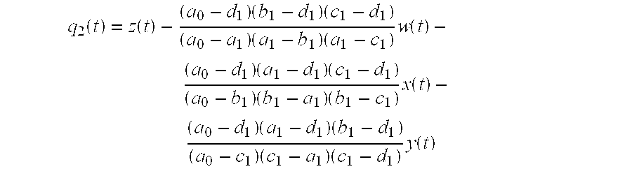
- where w, x, y and z are phase signals and where:
- w(t)=ƒ(t−a 1)−ƒ(t−a 0)
- x(t)=ƒ(t−b 1)−ƒ(t−b 0)
- y(t)=ƒ(t−c 1)−ƒ(t−c 0)
- z(t)=ƒ(t−d 1)−ƒ(t−d 0)
- and a 1, a0, b1, b0, c1, c0, and d1, d0 are path lengths.
- The above description and drawings are only illustrative of preferred embodiments which achieve the objects, features and advantages of the present invention, and it is not intended that the present invention be limited thereto. Any modification of the present invention which comes within the spirit and scope of the following claims is considered part of the present invention.
Claims (14)


Priority Applications (1)
| Application Number | Priority Date | Filing Date | Title |
|---|---|---|---|
| US10/816,517 US6900897B2 (en) | 2003-04-02 | 2004-04-01 | Apparatus and method for correcting errors generated by a laser with non-ideal tuning characteristics |
Applications Claiming Priority (2)
| Application Number | Priority Date | Filing Date | Title |
|---|---|---|---|
| US45985603P | 2003-04-02 | 2003-04-02 | |
| US10/816,517 US6900897B2 (en) | 2003-04-02 | 2004-04-01 | Apparatus and method for correcting errors generated by a laser with non-ideal tuning characteristics |
Publications (2)
| Publication Number | Publication Date |
|---|---|
| US20040196467A1 true US20040196467A1 (en) | 2004-10-07 |
| US6900897B2 US6900897B2 (en) | 2005-05-31 |
Family
ID=33159698
Family Applications (1)
| Application Number | Title | Priority Date | Filing Date |
|---|---|---|---|
| US10/816,517 Expired - Lifetime US6900897B2 (en) | 2003-04-02 | 2004-04-01 | Apparatus and method for correcting errors generated by a laser with non-ideal tuning characteristics |
Country Status (2)
| Country | Link |
|---|---|
| US (1) | US6900897B2 (en) |
| WO (1) | WO2004090507A2 (en) |
Cited By (5)
| Publication number | Priority date | Publication date | Assignee | Title |
|---|---|---|---|---|
| US20090046276A1 (en) * | 2007-08-17 | 2009-02-19 | U.S.A. as represented by the Administrator of the National Aeronautics and Spac Administration | System And Method For Determination Of The Reflection Wavelength Of Multiple Low-Reflectivity Bragg Gratings In A Sensing Optical Fiber |
| EP2976606A4 (en) * | 2013-03-19 | 2016-11-16 | Intuitive Surgical Operations | Methods and apparatus for simultaneous optical parameter measurements |
| US20170276470A1 (en) * | 2016-03-28 | 2017-09-28 | Anritsu Corporation | Optical frequency domain reflectometer and optical frequency domain reflectometry |
| JP2018185278A (en) * | 2017-04-27 | 2018-11-22 | アンリツ株式会社 | Optical frequency domain refractometry device and optical frequency domain refractometry method |
| EP3540401A1 (en) * | 2006-07-26 | 2019-09-18 | Intuitive Surgical Operations, Inc. | High resolution interferometric optical frequency domain reflectometry (ofdr) beyond the laser coherence length |
Families Citing this family (54)
| Publication number | Priority date | Publication date | Assignee | Title |
|---|---|---|---|---|
| WO2008027959A2 (en) * | 2006-08-31 | 2008-03-06 | Optellios, Inc | Detection and location of boundary intrusion, using composite variables derived from phase measurements |
| US8395782B2 (en) * | 2004-06-15 | 2013-03-12 | Optellios, Inc. | Detection and location of boundary intrusion, using composite variables derived from phase measurements |
| CA2590790C (en) | 2004-12-14 | 2014-09-02 | Luna Innovations Inc. | Compensating for time varying phase changes in interferometric measurements |
| US9867530B2 (en) | 2006-08-14 | 2018-01-16 | Volcano Corporation | Telescopic side port catheter device with imaging system and method for accessing side branch occlusions |
| WO2009009799A1 (en) | 2007-07-12 | 2009-01-15 | Volcano Corporation | Catheter for in vivo imaging |
| US9596993B2 (en) | 2007-07-12 | 2017-03-21 | Volcano Corporation | Automatic calibration systems and methods of use |
| US10219780B2 (en) | 2007-07-12 | 2019-03-05 | Volcano Corporation | OCT-IVUS catheter for concurrent luminal imaging |
| US7720322B2 (en) * | 2008-06-30 | 2010-05-18 | Intuitive Surgical, Inc. | Fiber optic shape sensor |
| US8773650B2 (en) | 2009-09-18 | 2014-07-08 | Intuitive Surgical Operations, Inc. | Optical position and/or shape sensing |
| US9025158B2 (en) | 2010-06-01 | 2015-05-05 | Intuitive Surgical Operations, Inc. | Interferometric measurement with crosstalk suppression |
| US11141063B2 (en) | 2010-12-23 | 2021-10-12 | Philips Image Guided Therapy Corporation | Integrated system architectures and methods of use |
| US11040140B2 (en) | 2010-12-31 | 2021-06-22 | Philips Image Guided Therapy Corporation | Deep vein thrombosis therapeutic methods |
| WO2013033592A1 (en) | 2011-08-31 | 2013-03-07 | Volcano Corporation | Optical-electrical rotary joint and methods of use |
| US9429696B2 (en) | 2012-06-25 | 2016-08-30 | Intuitive Surgical Operations, Inc. | Systems and methods for reducing measurement error in optical fiber shape sensors |
| US9324141B2 (en) | 2012-10-05 | 2016-04-26 | Volcano Corporation | Removal of A-scan streaking artifact |
| US11272845B2 (en) | 2012-10-05 | 2022-03-15 | Philips Image Guided Therapy Corporation | System and method for instant and automatic border detection |
| US10568586B2 (en) | 2012-10-05 | 2020-02-25 | Volcano Corporation | Systems for indicating parameters in an imaging data set and methods of use |
| US9286673B2 (en) | 2012-10-05 | 2016-03-15 | Volcano Corporation | Systems for correcting distortions in a medical image and methods of use thereof |
| US9292918B2 (en) | 2012-10-05 | 2016-03-22 | Volcano Corporation | Methods and systems for transforming luminal images |
| JP2015532536A (en) | 2012-10-05 | 2015-11-09 | デイビッド ウェルフォード, | System and method for amplifying light |
| US9858668B2 (en) | 2012-10-05 | 2018-01-02 | Volcano Corporation | Guidewire artifact removal in images |
| US10070827B2 (en) | 2012-10-05 | 2018-09-11 | Volcano Corporation | Automatic image playback |
| US9307926B2 (en) | 2012-10-05 | 2016-04-12 | Volcano Corporation | Automatic stent detection |
| US9367965B2 (en) | 2012-10-05 | 2016-06-14 | Volcano Corporation | Systems and methods for generating images of tissue |
| US9840734B2 (en) | 2012-10-22 | 2017-12-12 | Raindance Technologies, Inc. | Methods for analyzing DNA |
| JP6322210B2 (en) | 2012-12-13 | 2018-05-09 | ボルケーノ コーポレイション | Devices, systems, and methods for targeted intubation |
| JP2016504589A (en) | 2012-12-20 | 2016-02-12 | ナサニエル ジェイ. ケンプ, | Optical coherence tomography system reconfigurable between different imaging modes |
| US11406498B2 (en) | 2012-12-20 | 2022-08-09 | Philips Image Guided Therapy Corporation | Implant delivery system and implants |
| WO2014099899A1 (en) | 2012-12-20 | 2014-06-26 | Jeremy Stigall | Smooth transition catheters |
| US10942022B2 (en) | 2012-12-20 | 2021-03-09 | Philips Image Guided Therapy Corporation | Manual calibration of imaging system |
| EP2934282B1 (en) | 2012-12-20 | 2020-04-29 | Volcano Corporation | Locating intravascular images |
| US10939826B2 (en) | 2012-12-20 | 2021-03-09 | Philips Image Guided Therapy Corporation | Aspirating and removing biological material |
| CA2895769A1 (en) | 2012-12-21 | 2014-06-26 | Douglas Meyer | Rotational ultrasound imaging catheter with extended catheter body telescope |
| US9383263B2 (en) | 2012-12-21 | 2016-07-05 | Volcano Corporation | Systems and methods for narrowing a wavelength emission of light |
| WO2014099760A1 (en) | 2012-12-21 | 2014-06-26 | Mai Jerome | Ultrasound imaging with variable line density |
| US10191220B2 (en) | 2012-12-21 | 2019-01-29 | Volcano Corporation | Power-efficient optical circuit |
| JP2016501623A (en) | 2012-12-21 | 2016-01-21 | アンドリュー ハンコック, | System and method for multipath processing of image signals |
| US9486143B2 (en) | 2012-12-21 | 2016-11-08 | Volcano Corporation | Intravascular forward imaging device |
| US10413317B2 (en) | 2012-12-21 | 2019-09-17 | Volcano Corporation | System and method for catheter steering and operation |
| JP2016508757A (en) | 2012-12-21 | 2016-03-24 | ジェイソン スペンサー, | System and method for graphical processing of medical data |
| US9612105B2 (en) | 2012-12-21 | 2017-04-04 | Volcano Corporation | Polarization sensitive optical coherence tomography system |
| US10058284B2 (en) | 2012-12-21 | 2018-08-28 | Volcano Corporation | Simultaneous imaging, monitoring, and therapy |
| US10226597B2 (en) | 2013-03-07 | 2019-03-12 | Volcano Corporation | Guidewire with centering mechanism |
| US9770172B2 (en) | 2013-03-07 | 2017-09-26 | Volcano Corporation | Multimodal segmentation in intravascular images |
| US20140276923A1 (en) | 2013-03-12 | 2014-09-18 | Volcano Corporation | Vibrating catheter and methods of use |
| CN105228518B (en) | 2013-03-12 | 2018-10-09 | 火山公司 | System and method for diagnosing coronal microvascular diseases |
| CN105120759B (en) | 2013-03-13 | 2018-02-23 | 火山公司 | System and method for producing image from rotation intravascular ultrasound equipment |
| US11026591B2 (en) | 2013-03-13 | 2021-06-08 | Philips Image Guided Therapy Corporation | Intravascular pressure sensor calibration |
| US9301687B2 (en) | 2013-03-13 | 2016-04-05 | Volcano Corporation | System and method for OCT depth calibration |
| US10219887B2 (en) | 2013-03-14 | 2019-03-05 | Volcano Corporation | Filters with echogenic characteristics |
| US10292677B2 (en) | 2013-03-14 | 2019-05-21 | Volcano Corporation | Endoluminal filter having enhanced echogenic properties |
| CN105208947B (en) | 2013-03-14 | 2018-10-12 | 火山公司 | Filter with echoing characteristic |
| JP7046843B2 (en) * | 2016-06-29 | 2022-04-04 | インテュイティブ サージカル オペレーションズ, インコーポレイテッド | Methods and equipment for OFDR call monitoring and optimization |
| US11592354B2 (en) * | 2021-02-03 | 2023-02-28 | Nokia Solutions And Networks Oy | Phase-distortion mitigation for an optical vector network analyzer |
Citations (4)
| Publication number | Priority date | Publication date | Assignee | Title |
|---|---|---|---|---|
| US5798521A (en) * | 1996-02-27 | 1998-08-25 | The United States Of America As Represented By The Administrator Of The National Aeronautics And Space Administration | Apparatus and method for measuring strain in bragg gratings |
| US6376830B1 (en) * | 1999-09-14 | 2002-04-23 | The United States Of America As Represented By The Administrator Of The National Aeronautics And Space Administration | System and method for measuring the transfer function of a guided wave device |
| US6545760B1 (en) * | 1999-03-25 | 2003-04-08 | The United States Of America As Represented By The Administrator Of The National Aeronautics And Space Administration | Apparatus and method for measuring strain in optical fibers using rayleigh scatter |
| US6566648B1 (en) * | 1999-03-25 | 2003-05-20 | The United States Of America As Represented By The United States National Aeronautics And Space Administration | Edge triggered apparatus and method for measuring strain in bragg gratings |
-
2004
- 2004-04-01 WO PCT/US2004/009991 patent/WO2004090507A2/en active Application Filing
- 2004-04-01 US US10/816,517 patent/US6900897B2/en not_active Expired - Lifetime
Patent Citations (4)
| Publication number | Priority date | Publication date | Assignee | Title |
|---|---|---|---|---|
| US5798521A (en) * | 1996-02-27 | 1998-08-25 | The United States Of America As Represented By The Administrator Of The National Aeronautics And Space Administration | Apparatus and method for measuring strain in bragg gratings |
| US6545760B1 (en) * | 1999-03-25 | 2003-04-08 | The United States Of America As Represented By The Administrator Of The National Aeronautics And Space Administration | Apparatus and method for measuring strain in optical fibers using rayleigh scatter |
| US6566648B1 (en) * | 1999-03-25 | 2003-05-20 | The United States Of America As Represented By The United States National Aeronautics And Space Administration | Edge triggered apparatus and method for measuring strain in bragg gratings |
| US6376830B1 (en) * | 1999-09-14 | 2002-04-23 | The United States Of America As Represented By The Administrator Of The National Aeronautics And Space Administration | System and method for measuring the transfer function of a guided wave device |
Cited By (6)
| Publication number | Priority date | Publication date | Assignee | Title |
|---|---|---|---|---|
| EP3540401A1 (en) * | 2006-07-26 | 2019-09-18 | Intuitive Surgical Operations, Inc. | High resolution interferometric optical frequency domain reflectometry (ofdr) beyond the laser coherence length |
| US20090046276A1 (en) * | 2007-08-17 | 2009-02-19 | U.S.A. as represented by the Administrator of the National Aeronautics and Spac Administration | System And Method For Determination Of The Reflection Wavelength Of Multiple Low-Reflectivity Bragg Gratings In A Sensing Optical Fiber |
| US7538860B2 (en) | 2007-08-17 | 2009-05-26 | The United States Of America As Represented By The Administrator Of The National Aeronautics And Space Administration | System and method for determination of the reflection wavelength of multiple low-reflectivity bragg gratings in a sensing optical fiber |
| EP2976606A4 (en) * | 2013-03-19 | 2016-11-16 | Intuitive Surgical Operations | Methods and apparatus for simultaneous optical parameter measurements |
| US20170276470A1 (en) * | 2016-03-28 | 2017-09-28 | Anritsu Corporation | Optical frequency domain reflectometer and optical frequency domain reflectometry |
| JP2018185278A (en) * | 2017-04-27 | 2018-11-22 | アンリツ株式会社 | Optical frequency domain refractometry device and optical frequency domain refractometry method |
Also Published As
| Publication number | Publication date |
|---|---|
| WO2004090507A3 (en) | 2005-04-14 |
| WO2004090507A2 (en) | 2004-10-21 |
| US6900897B2 (en) | 2005-05-31 |
Similar Documents
| Publication | Publication Date | Title |
|---|---|---|
| US6900897B2 (en) | Apparatus and method for correcting errors generated by a laser with non-ideal tuning characteristics | |
| EP1365218B1 (en) | Wavelength meter for swept lasers | |
| US10545070B2 (en) | Dispersion correction in optical frequency-domain reflectometry | |
| US6570894B2 (en) | Real-time wavelength calibration for swept lasers | |
| US8625101B2 (en) | Referencing of the beating spectra of frequency combs | |
| EP3540401B1 (en) | High resolution interferometric optical frequency domain reflectometry (ofdr) | |
| US6486961B1 (en) | System and method for measuring group delay based on zero-crossings | |
| US20020149779A1 (en) | Wavelength measurement adjustment | |
| US11499849B2 (en) | Method and apparatus for suppression of noise due to transmitted signal instability in a coherent fiber optical sensor system | |
| US7109471B2 (en) | Optical wavelength determination using multiple measurable features | |
| US20200408572A1 (en) | Method and apparatus for suppression of noise due to local oscillator instability in a coherent fiber optical sensor | |
| US20170023628A1 (en) | Time corrected time-domain reflectometer | |
| CN112923960A (en) | Optical fiber parameter measuring device for correcting nonlinear tuning effect | |
| US20030107743A1 (en) | Phase noise compensation in an interferometric system | |
| AU6022896A (en) | Measurement of polarization mode dispersion | |
| US7079253B2 (en) | Tracking of a tunable laser over output discontinuities | |
| Judah et al. | A novel sixport calibration incorporating diode detector non-linearity | |
| Akeson | Fast-switching cycle times for BIMA's A array | |
| CN103874911B (en) | The method compensating frequency drift in interferometer | |
| Li et al. | Research on large range OFDR distributed temperature sensing technology based on frequency sampling and moving reference spectral method | |
| Hlupic et al. | Common systematic errors in sampling applications and their compensation | |
| CN103874911A (en) | Method of compensating frequency drift in an interferometer |
Legal Events
| Date | Code | Title | Description |
|---|---|---|---|
| AS | Assignment |
Owner name: LUNA TECHNOLOGIES, INCORPORATED, VIRGINIA Free format text: ASSIGNMENT OF ASSIGNORS INTEREST;ASSIGNOR:FROGGATT, MARK E;REEL/FRAME:015136/0597 Effective date: 20040817 |
|
| STCF | Information on status: patent grant |
Free format text: PATENTED CASE |
|
| FEPP | Fee payment procedure |
Free format text: PAT HOLDER NO LONGER CLAIMS SMALL ENTITY STATUS, ENTITY STATUS SET TO UNDISCOUNTED (ORIGINAL EVENT CODE: STOL); ENTITY STATUS OF PATENT OWNER: LARGE ENTITY |
|
| AS | Assignment |
Owner name: LUNA INNOVATIONS INCORPORATED, VIRGINIA Free format text: ASSIGNMENT OF ASSIGNORS INTEREST;ASSIGNOR:LUNA TECHNOLOGIES INCORPORATED;REEL/FRAME:018731/0566 Effective date: 20061220 |
|
| FPAY | Fee payment |
Year of fee payment: 4 |
|
| AS | Assignment |
Owner name: HANSEN MEDICAL, INC., CALIFORNIA Free format text: SECURITY AGREEMENT;ASSIGNOR:LUNA INNOVATIONS INCORPORATED;REEL/FRAME:023792/0388 Effective date: 20100112 Owner name: HANSEN MEDICAL, INC.,CALIFORNIA Free format text: SECURITY AGREEMENT;ASSIGNOR:LUNA INNOVATIONS INCORPORATED;REEL/FRAME:023792/0388 Effective date: 20100112 |
|
| AS | Assignment |
Owner name: SILICON VALLEY BANK,MASSACHUSETTS Free format text: SECURITY AGREEMENT;ASSIGNOR:LUNA INNOVATIONS INCORPORATED;REEL/FRAME:023985/0718 Effective date: 20100218 Owner name: SILICON VALLEY BANK, MASSACHUSETTS Free format text: SECURITY AGREEMENT;ASSIGNOR:LUNA INNOVATIONS INCORPORATED;REEL/FRAME:023985/0718 Effective date: 20100218 |
|
| AS | Assignment |
Owner name: KONINKLIJKE PHILIPS ELECTRONICS N V, NETHERLANDS Free format text: SECURITY AGREEMENT;ASSIGNOR:ECL7, LLC;REEL/FRAME:026468/0920 Effective date: 20110203 Owner name: PHILIPS MEDICAL SYSTEMS NEDERLAND B.V., NETHERLAND Free format text: SECURITY AGREEMENT;ASSIGNOR:ECL7, LLC;REEL/FRAME:026468/0920 Effective date: 20110203 |
|
| FPAY | Fee payment |
Year of fee payment: 8 |
|
| SULP | Surcharge for late payment |
Year of fee payment: 7 |
|
| AS | Assignment |
Owner name: LUNA INNOVATIONS INCORPORATED, VIRGINIA Free format text: RELEASE BY SECURED PARTY;ASSIGNOR:HANSEN MEDICAL, INC.;REEL/FRAME:031784/0755 Effective date: 20110518 |
|
| AS | Assignment |
Owner name: INTUITIVE SURGICAL OPERATIONS, INC., CALIFORNIA Free format text: ASSIGNMENT OF ASSIGNORS INTEREST;ASSIGNOR:LUNA INNOVATIONS INCORPORATED;REEL/FRAME:032355/0264 Effective date: 20140117 |
|
| REMI | Maintenance fee reminder mailed | ||
| FPAY | Fee payment |
Year of fee payment: 12 |
|
| SULP | Surcharge for late payment |
Year of fee payment: 11 |