US20040256830A1 - Strut-type suspension device - Google Patents
Strut-type suspension device Download PDFInfo
- Publication number
- US20040256830A1 US20040256830A1 US10/463,905 US46390503A US2004256830A1 US 20040256830 A1 US20040256830 A1 US 20040256830A1 US 46390503 A US46390503 A US 46390503A US 2004256830 A1 US2004256830 A1 US 2004256830A1
- Authority
- US
- United States
- Prior art keywords
- strut
- bearing
- kingpin axis
- vehicle body
- axis
- Prior art date
- Legal status (The legal status is an assumption and is not a legal conclusion. Google has not performed a legal analysis and makes no representation as to the accuracy of the status listed.)
- Granted
Links
Images


Classifications
-
- B—PERFORMING OPERATIONS; TRANSPORTING
- B60—VEHICLES IN GENERAL
- B60G—VEHICLE SUSPENSION ARRANGEMENTS
- B60G15/00—Resilient suspensions characterised by arrangement, location or type of combined spring and vibration damper, e.g. telescopic type
- B60G15/02—Resilient suspensions characterised by arrangement, location or type of combined spring and vibration damper, e.g. telescopic type having mechanical spring
- B60G15/06—Resilient suspensions characterised by arrangement, location or type of combined spring and vibration damper, e.g. telescopic type having mechanical spring and fluid damper
- B60G15/067—Resilient suspensions characterised by arrangement, location or type of combined spring and vibration damper, e.g. telescopic type having mechanical spring and fluid damper characterised by the mounting on the vehicle body or chassis of the spring and damper unit
- B60G15/068—Resilient suspensions characterised by arrangement, location or type of combined spring and vibration damper, e.g. telescopic type having mechanical spring and fluid damper characterised by the mounting on the vehicle body or chassis of the spring and damper unit specially adapted for MacPherson strut-type suspension
-
- B—PERFORMING OPERATIONS; TRANSPORTING
- B60—VEHICLES IN GENERAL
- B60G—VEHICLE SUSPENSION ARRANGEMENTS
- B60G2204/00—Indexing codes related to suspensions per se or to auxiliary parts
- B60G2204/10—Mounting of suspension elements
- B60G2204/12—Mounting of springs or dampers
- B60G2204/128—Damper mount on vehicle body or chassis
Definitions
- the present invention relates to a strut-type suspension device for an automobile and in particular relates to a construction thereof for improving the straight traveling stability during driving in a straight path.
- an insulator 3 holding an elastic rubber element 2 in its interior is provided in a vehicle body 1 .
- the upper end of a strut 7 is held in the elastic rubber element 2 within this insulator 3 and an upper seat 5 is arranged below the insulator 3 , with a bearing 4 interposed therebetween.
- a lower seat 8 is fixed to the strut 7 and a compression coil spring 6 is held between this upper seat 5 and the lower seat 8 .
- the central axis of the bearing coincides with the axis of the strut. 9 is the axis of a kingpin.
- Japanese Utility Model Publication No. S61-93305A discloses improvements in a strut-type suspension device arranged such that torsion of the spring generated when the spring is displaced is released, by mounting a self-aligning bearing on an upper seat or a lower seat.
- FIG. 5 is a diagram of the operation of a conventional strut-type suspension device.
- the bearing is arranged so as to intersect the strut axis 12 (the double-dotted chain line) at right angles.
- FIG. 6 shows an imaginary plane at the upper seat of FIG. 5.
- the origin of the X and Y co-ordinates is centered on the strut axis 12 , the forward direction of the vehicle body being X and the width direction of the vehicle body being Y.
- the point where the line of action of the load 14 intersects the upper seat or lower seat is called a point of action of the load 15 .
- the relationship between the rotation angle ⁇ about the kingpin axis and the strain energy stored in the spring when the kingpin axis is shifted in the X direction will now be examined wherein the point of action of the load is fixed.
- the rotation angle about the kingpin axis means the angle by which the upper or lower sheet rotates about the kingpin axis, unless otherwise specified.
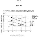
- FIG. 7 shows the relationship between the rotation angle ⁇ and the strain energy in the prior art device when the bearing axis and the strut axis coincide.
- An object of the present invention is to provide a strut-type suspension device wherein the strain energy of the spring is unchanged irrespective of the rotation angle ⁇ about the kingpin axis, even if the amount of the above-mentioned eccentricity varies.
- a strut type suspension device which comprises a strut whose upper end is supported on an insulator mounted on a vehicle body, an upper seat arranged below the vehicle body with a bearing interposed therebetween, a lower seat fixed to said strut, and a compression coil spring arranged coiled around the strut between the upper seat and the lower seat and which supports the vehicle body by means of the strut and is capable of turning about a kingpin axis, wherein the bearing is arranged in inclined fashion such that the kingpin axis and the bearing central axis roughly coincide, so that no rotation moment is generated about the kingpin axis.
- FIG. 1 is a constructional diagram of an embodiment of the present invention.
- FIG. 2 is a graph showing the relationship between the rotation angle about the kingpin axis and the strain energy of the spring according to the present invention.
- FIG. 3 is a constructional diagram of another embodiment of the present invention.
- FIG. 4 is a constructional diagram of a prior art example.
- FIG. 5 is a diagram of the operation of the prior art example
- FIG. 6 is a view showing the co-ordinates and the basis for measuring the rotation angle about the kingpin axis at the position of the upper seat in order to illustrate the function.
- FIG. 7 is a graph showing the relationship between the rotation angle about the kingpin axis and the strain energy of the spring in the prior art example.
- FIG. 1 An embodiment of the present invention is described with reference to FIG. 1. Parts that are referred to by the same names as in the case of FIG. 4 are shown with the same reference symbols.
- Both the upper seat and the lower seat rotate about the kingpin axis. Since there is no change in the relative angle and distance between the upper seat and the lower seat when the upper seat and the lower seat are simultaneously rotated, there can be no change in the strain energy of the coil spring.
- FIG. 3 is a constructional diagram showing another embodiment of the present invention. Parts that are referred to by the same names as in the case of FIG. 1 and FIG. 4 are shown with the same reference symbols.
- the shape of the upper sheet 5 and the insulator 3 is formed such that the bearing 4 is perpendicular with respect to the kingpin axis 9 .
- an angle adjusting member 10 is integrally formed on a support member below the insulator 3 , so insertion of an angle adjusting member 10 as shown in FIG. 1 as a separate member is unnecessary.
- the upper sheet 5 is inclined at an angle as shown in the Figure, so insertion of an angle adjusting member 11 as a separate member is not required either.
- the relationship between the rotation angle about the kingpin axis and the strain energy of the spring can always be maintained constant by using only a single suspension device, and the straight traveling stability can be improved.
- a construction displaying this effect can easily be implemented in the prior art construction by using the angle adjusting members to adjust the angle of the bearing so that the kingpin axis and the bearing centerline roughly coincide.
Abstract
Description
- 1. Field of the Invention
- The present invention relates to a strut-type suspension device for an automobile and in particular relates to a construction thereof for improving the straight traveling stability during driving in a straight path.
- 2. Description of the Related Art
- As shown in FIG. 4, in a conventional strut-type suspension device, an
insulator 3 holding anelastic rubber element 2 in its interior is provided in avehicle body 1. The upper end of astrut 7 is held in theelastic rubber element 2 within thisinsulator 3 and anupper seat 5 is arranged below theinsulator 3, with a bearing 4 interposed therebetween. Alower seat 8 is fixed to thestrut 7 and acompression coil spring 6 is held between thisupper seat 5 and thelower seat 8. In this case, the central axis of the bearing coincides with the axis of the strut. 9 is the axis of a kingpin. - Japanese Utility Model Publication No. S61-93305A discloses improvements in a strut-type suspension device arranged such that torsion of the spring generated when the spring is displaced is released, by mounting a self-aligning bearing on an upper seat or a lower seat.
- Also, in Laid-open Japanese Patent Publication No. 9-300932A, rotation moment is generated in the opposite directions in the right side suspension means and the left side suspension means. One of the beneficial effects of this is that lowering of straight traveling stability is avoided.
- FIG. 5 is a diagram of the operation of a conventional strut-type suspension device. In this case, the bearing is arranged so as to intersect the strut axis 12 (the double-dotted chain line) at right angles. The
upper seat 5 rotates about the strut axis 12 (=bearing axis 13) and thelower seat 8 rotates about the kingpin axis 9 (single-dotted chain line). Since theupper seat 5 and thelower seat 8 have respectively different axes of rotation, in general, a moment is generated about the kingpin, impairing the straight traveling stability. - FIG. 6 shows an imaginary plane at the upper seat of FIG. 5. The origin of the X and Y co-ordinates is centered on the
strut axis 12, the forward direction of the vehicle body being X and the width direction of the vehicle body being Y. The point where the line of action of theload 14 intersects the upper seat or lower seat is called a point of action of theload 15. The relationship between the rotation angle θ about the kingpin axis and the strain energy stored in the spring when the kingpin axis is shifted in the X direction will now be examined wherein the point of action of the load is fixed. Throughout the specification, the rotation angle about the kingpin axis means the angle by which the upper or lower sheet rotates about the kingpin axis, unless otherwise specified. - FIG. 7 shows the relationship between the rotation angle θ and the strain energy in the prior art device when the bearing axis and the strut axis coincide. Taking the amount of eccentricity of the point of action of the load from the Y-axis as a parameter, it can be seen from the Figure that the strain energy of the spring varies with the rotation angle θ. Rotation of both the upper and lower seats therefore takes place in the direction such as to reduce the strain energy. For example if the amount of eccentricity is −10.3 mm, rotation takes place with an rotation angle θ in the negative direction and if the amount of eccentricity is 18 mm rotation takes place with an rotation angle θ in the positive direction. This appears as a rotation moment about the kingpin.
- It can also be seen from FIG. 7 that the direction of the rotation moment generated changes depending on whether the amount of eccentricity in the X direction is positive or negative. Consequently, if the amount of eccentricity is zero, even if rotation takes place, the strain energy is constant and a rotation moment is not generated.
- An object of the present invention is to provide a strut-type suspension device wherein the strain energy of the spring is unchanged irrespective of the rotation angle θ about the kingpin axis, even if the amount of the above-mentioned eccentricity varies.
- According to the present invention there is provided a strut type suspension device which comprises a strut whose upper end is supported on an insulator mounted on a vehicle body, an upper seat arranged below the vehicle body with a bearing interposed therebetween, a lower seat fixed to said strut, and a compression coil spring arranged coiled around the strut between the upper seat and the lower seat and which supports the vehicle body by means of the strut and is capable of turning about a kingpin axis, wherein the bearing is arranged in inclined fashion such that the kingpin axis and the bearing central axis roughly coincide, so that no rotation moment is generated about the kingpin axis.
- FIG. 1 is a constructional diagram of an embodiment of the present invention.
- FIG. 2 is a graph showing the relationship between the rotation angle about the kingpin axis and the strain energy of the spring according to the present invention.
- FIG. 3 is a constructional diagram of another embodiment of the present invention.
- FIG. 4 is a constructional diagram of a prior art example.
- FIG. 5 is a diagram of the operation of the prior art example;
- FIG. 6 is a view showing the co-ordinates and the basis for measuring the rotation angle about the kingpin axis at the position of the upper seat in order to illustrate the function.
- FIG. 7 is a graph showing the relationship between the rotation angle about the kingpin axis and the strain energy of the spring in the prior art example.
- An embodiment of the present invention is described with reference to FIG. 1. Parts that are referred to by the same names as in the case of FIG. 4 are shown with the same reference symbols.
- The relationship of the
vehicle body 1,elastic rubber element 2,insulator 3,compression coil spring 6,strut 7,upper seat 5 andlower seat 8 is the same as in the case of the prior art example shown in FIG. 4. However, thebearing 4 that is mounted on theupper seat 5 is mounted with an angle, usingangle adjusting members insulator 3, so that the centerline of thebearing 4 roughly coincides with thekingpin axis 9. - Both the upper seat and the lower seat rotate about the kingpin axis. Since there is no change in the relative angle and distance between the upper seat and the lower seat when the upper seat and the lower seat are simultaneously rotated, there can be no change in the strain energy of the coil spring.
- By adopting such a construction, a relationship between the rotation angle about the kingpin axis and the strain energy of the spring as shown in FIG. 2 is achieved. As shown in FIG. 2, irrespective of the amount of eccentricity in the X direction, the strain energy of the spring is constant in the same manner as when the amount of eccentricity in the X direction in FIG. 7 is 0 mm. Thus, no rotation moment is generated and high straight traveling stability is achieved.
- FIG. 3 is a constructional diagram showing another embodiment of the present invention. Parts that are referred to by the same names as in the case of FIG. 1 and FIG. 4 are shown with the same reference symbols. The shape of the
upper sheet 5 and theinsulator 3 is formed such that thebearing 4 is perpendicular with respect to thekingpin axis 9. In this embodiment, anangle adjusting member 10 is integrally formed on a support member below theinsulator 3, so insertion of anangle adjusting member 10 as shown in FIG. 1 as a separate member is unnecessary. Also, theupper sheet 5 is inclined at an angle as shown in the Figure, so insertion of anangle adjusting member 11 as a separate member is not required either. - According to the present invention, without large-scale alteration of the prior art construction, the relationship between the rotation angle about the kingpin axis and the strain energy of the spring can always be maintained constant by using only a single suspension device, and the straight traveling stability can be improved. A construction displaying this effect can easily be implemented in the prior art construction by using the angle adjusting members to adjust the angle of the bearing so that the kingpin axis and the bearing centerline roughly coincide.
Claims (1)
Priority Applications (2)
| Application Number | Priority Date | Filing Date | Title |
|---|---|---|---|
| US10/463,905 US7690662B2 (en) | 2003-06-18 | 2003-06-18 | Strut-type suspension device |
| CA002432764A CA2432764C (en) | 2003-06-18 | 2003-06-18 | Strut-type suspension device |
Applications Claiming Priority (2)
| Application Number | Priority Date | Filing Date | Title |
|---|---|---|---|
| US10/463,905 US7690662B2 (en) | 2003-06-18 | 2003-06-18 | Strut-type suspension device |
| CA002432764A CA2432764C (en) | 2003-06-18 | 2003-06-18 | Strut-type suspension device |
Publications (2)
| Publication Number | Publication Date |
|---|---|
| US20040256830A1 true US20040256830A1 (en) | 2004-12-23 |
| US7690662B2 US7690662B2 (en) | 2010-04-06 |
Family
ID=34137150
Family Applications (1)
| Application Number | Title | Priority Date | Filing Date |
|---|---|---|---|
| US10/463,905 Expired - Lifetime US7690662B2 (en) | 2003-06-18 | 2003-06-18 | Strut-type suspension device |
Country Status (2)
| Country | Link |
|---|---|
| US (1) | US7690662B2 (en) |
| CA (1) | CA2432764C (en) |
Cited By (6)
| Publication number | Priority date | Publication date | Assignee | Title |
|---|---|---|---|---|
| US20040178596A1 (en) * | 2003-03-14 | 2004-09-16 | Mazda Motor Corporation | Front suspension device for automotive vehicle |
| US20050258614A1 (en) * | 2004-05-18 | 2005-11-24 | Dove Jason L | Linear suspension spring |
| US20060076751A1 (en) * | 2004-09-27 | 2006-04-13 | Toyota Jidosha Kabushiki Kaisha | Strut suspension |
| KR100633945B1 (en) * | 2005-05-10 | 2006-10-13 | 현대자동차주식회사 | Mount structure of strut insulator which can be variable of camber and caster |
| JP2015168393A (en) * | 2014-03-10 | 2015-09-28 | トヨタ自動車株式会社 | Strut type suspension device |
| DE102009047404B4 (en) | 2009-12-02 | 2021-07-29 | Ford Global Technologies, Llc | Suspension |
Families Citing this family (1)
| Publication number | Priority date | Publication date | Assignee | Title |
|---|---|---|---|---|
| US20080303196A1 (en) * | 2007-06-05 | 2008-12-11 | Steeda Autosports, Inc. | Upper strut mount assembly |
Citations (11)
| Publication number | Priority date | Publication date | Assignee | Title |
|---|---|---|---|---|
| US4105222A (en) * | 1976-11-26 | 1978-08-08 | General Motors Corporation | Independent front suspension system |
| US4274655A (en) * | 1979-10-29 | 1981-06-23 | General Motors Corporation | Resilient mount for MacPherson strut |
| USRE31184E (en) * | 1979-10-29 | 1983-03-22 | General Motors Corporation | Resilient mount for MacPherson strut |
| US4756517A (en) * | 1984-09-05 | 1988-07-12 | Nissan Motor Company, Limited | Strut suspension structure of automobile vehicle with variable geometry |
| US5074579A (en) * | 1989-11-14 | 1991-12-24 | Fiat Auto S.P.A. | McPherson-type suspension unit for motor vehicles |
| US5454585A (en) * | 1994-08-08 | 1995-10-03 | General Motors Corporation | Strut assembly with bearing axis alignment |
| US5467971A (en) * | 1994-08-08 | 1995-11-21 | General Motors Corporation | Strut assembly with integral bearing and spring seat |
| US5678808A (en) * | 1995-09-18 | 1997-10-21 | General Motors Corporation | Suspension strut assembly |
| US6199882B1 (en) * | 1998-07-31 | 2001-03-13 | Chuo Hatsujo Kabushiki Kaisha | Vehicle wheel suspension |
| US6367830B1 (en) * | 1999-03-15 | 2002-04-09 | Delphi Technologies, Inc. | Steering knuckle and suspension module |
| US6923461B2 (en) * | 2000-11-17 | 2005-08-02 | Mitsubishi Jidosha Kogyo Kabushiki Kaisha | Strut suspension system with dual-path top mounts |
Family Cites Families (4)
| Publication number | Priority date | Publication date | Assignee | Title |
|---|---|---|---|---|
| JPS6193305A (en) | 1984-10-12 | 1986-05-12 | Matsushita Electric Ind Co Ltd | Liquid fuel burner |
| JPS61200017A (en) | 1985-03-04 | 1986-09-04 | Nissan Motor Co Ltd | Upper mount construction of strut |
| JP2715666B2 (en) | 1990-12-27 | 1998-02-18 | 日産自動車株式会社 | Strut type suspension device |
| JPH09300932A (en) | 1996-05-20 | 1997-11-25 | Toyota Motor Corp | Suspension device |
-
2003
- 2003-06-18 US US10/463,905 patent/US7690662B2/en not_active Expired - Lifetime
- 2003-06-18 CA CA002432764A patent/CA2432764C/en not_active Expired - Lifetime
Patent Citations (11)
| Publication number | Priority date | Publication date | Assignee | Title |
|---|---|---|---|---|
| US4105222A (en) * | 1976-11-26 | 1978-08-08 | General Motors Corporation | Independent front suspension system |
| US4274655A (en) * | 1979-10-29 | 1981-06-23 | General Motors Corporation | Resilient mount for MacPherson strut |
| USRE31184E (en) * | 1979-10-29 | 1983-03-22 | General Motors Corporation | Resilient mount for MacPherson strut |
| US4756517A (en) * | 1984-09-05 | 1988-07-12 | Nissan Motor Company, Limited | Strut suspension structure of automobile vehicle with variable geometry |
| US5074579A (en) * | 1989-11-14 | 1991-12-24 | Fiat Auto S.P.A. | McPherson-type suspension unit for motor vehicles |
| US5454585A (en) * | 1994-08-08 | 1995-10-03 | General Motors Corporation | Strut assembly with bearing axis alignment |
| US5467971A (en) * | 1994-08-08 | 1995-11-21 | General Motors Corporation | Strut assembly with integral bearing and spring seat |
| US5678808A (en) * | 1995-09-18 | 1997-10-21 | General Motors Corporation | Suspension strut assembly |
| US6199882B1 (en) * | 1998-07-31 | 2001-03-13 | Chuo Hatsujo Kabushiki Kaisha | Vehicle wheel suspension |
| US6367830B1 (en) * | 1999-03-15 | 2002-04-09 | Delphi Technologies, Inc. | Steering knuckle and suspension module |
| US6923461B2 (en) * | 2000-11-17 | 2005-08-02 | Mitsubishi Jidosha Kogyo Kabushiki Kaisha | Strut suspension system with dual-path top mounts |
Cited By (12)
| Publication number | Priority date | Publication date | Assignee | Title |
|---|---|---|---|---|
| US20040178596A1 (en) * | 2003-03-14 | 2004-09-16 | Mazda Motor Corporation | Front suspension device for automotive vehicle |
| US7219909B2 (en) * | 2003-03-14 | 2007-05-22 | Mazda Motor Corporation | Front suspension device for automotive vehicle |
| US20050258614A1 (en) * | 2004-05-18 | 2005-11-24 | Dove Jason L | Linear suspension spring |
| US7185903B2 (en) * | 2004-05-18 | 2007-03-06 | Dove Jason L | Linear suspension spring |
| US20060076751A1 (en) * | 2004-09-27 | 2006-04-13 | Toyota Jidosha Kabushiki Kaisha | Strut suspension |
| US7540515B2 (en) * | 2004-09-27 | 2009-06-02 | Toyota Jidosha Kabushiki Kaisha | Strut suspension |
| KR100633945B1 (en) * | 2005-05-10 | 2006-10-13 | 현대자동차주식회사 | Mount structure of strut insulator which can be variable of camber and caster |
| DE102009047404B4 (en) | 2009-12-02 | 2021-07-29 | Ford Global Technologies, Llc | Suspension |
| JP2015168393A (en) * | 2014-03-10 | 2015-09-28 | トヨタ自動車株式会社 | Strut type suspension device |
| CN106103146A (en) * | 2014-03-10 | 2016-11-09 | 丰田自动车株式会社 | Strut type suspension system |
| TWI576258B (en) * | 2014-03-10 | 2017-04-01 | 豐田自動車股份有限公司 | Strut-type suspension device |
| US9662953B2 (en) | 2014-03-10 | 2017-05-30 | Toyota Jidosha Kabushiki Kaisha | Strut-type suspension device |
Also Published As
| Publication number | Publication date |
|---|---|
| CA2432764A1 (en) | 2004-12-18 |
| US7690662B2 (en) | 2010-04-06 |
| CA2432764C (en) | 2007-10-16 |
Similar Documents
| Publication | Publication Date | Title |
|---|---|---|
| US7284765B1 (en) | Torsion beam suspension | |
| US7588261B2 (en) | Suspension device | |
| US20090160153A1 (en) | Wheel Suspension for a Front Axle of a Motor Vehicle | |
| US6945547B2 (en) | Multi-link independent rear suspension assembly | |
| US10279640B2 (en) | Wheel suspension with centrally pivoted transverse leaf spring | |
| US7427113B2 (en) | Ball and socket mount for shock absorber of torsion beam axle suspension | |
| US8585065B2 (en) | Suspension structure and method of making suspension link | |
| US10589589B2 (en) | Integrated steering yoke and spring seat for suspension systems | |
| US7419174B2 (en) | Strut type suspension | |
| US20040256830A1 (en) | Strut-type suspension device | |
| US5826894A (en) | Alignment cam position limiter | |
| JP3468014B2 (en) | Trailing arm support structure for vehicle suspension | |
| US6843491B2 (en) | Rear suspension system | |
| JP2005506922A (en) | Method and apparatus for suspending a vehicle wheel assembly | |
| JP3766285B2 (en) | Strut type suspension system | |
| JPH09290761A (en) | Mounting structure for steering gear box | |
| JP2528603B2 (en) | Car suspension | |
| JPH0126483Y2 (en) | ||
| JP2007131272A (en) | Vehicle height sensor | |
| JPH0357528Y2 (en) | ||
| JPH07164847A (en) | Mount structure of suspension member | |
| KR20030080475A (en) | a suspension system of vehicles | |
| JP2022154815A (en) | Suspension device of automobile | |
| JPH02225113A (en) | Suspension for vehicle | |
| CN112744044A (en) | Novel torsion beam suspension structure |
Legal Events
| Date | Code | Title | Description |
|---|---|---|---|
| AS | Assignment |
Owner name: MITSUBISHI STEEL MFG. CO., LTD.,JAPAN Free format text: ASSIGNMENT OF ASSIGNORS INTEREST;ASSIGNORS:OMI, TOSHIO;SUGIMOTO, YUKIHIRO;REEL/FRAME:014204/0140 Effective date: 20030606 Owner name: MITSUBISHI STEEL MFG. CO., LTD., JAPAN Free format text: ASSIGNMENT OF ASSIGNORS INTEREST;ASSIGNORS:OMI, TOSHIO;SUGIMOTO, YUKIHIRO;REEL/FRAME:014204/0140 Effective date: 20030606 |
|
| FEPP | Fee payment procedure |
Free format text: PAYOR NUMBER ASSIGNED (ORIGINAL EVENT CODE: ASPN); ENTITY STATUS OF PATENT OWNER: LARGE ENTITY |
|
| STCF | Information on status: patent grant |
Free format text: PATENTED CASE |
|
| FPAY | Fee payment |
Year of fee payment: 4 |
|
| MAFP | Maintenance fee payment |
Free format text: PAYMENT OF MAINTENANCE FEE, 8TH YEAR, LARGE ENTITY (ORIGINAL EVENT CODE: M1552) Year of fee payment: 8 |
|
| MAFP | Maintenance fee payment |
Free format text: PAYMENT OF MAINTENANCE FEE, 12TH YEAR, LARGE ENTITY (ORIGINAL EVENT CODE: M1553); ENTITY STATUS OF PATENT OWNER: LARGE ENTITY Year of fee payment: 12 |