-
This application claims priority from U.S. Provisional Application Ser. No. 60/472,290, filed May 21, 2003, the entire content of which is incorporated herein by reference.
STATEMENT REGARDING FEDERALLY SPONSORED RESEARCH OR DEVELOPMENT
-
This invention was made with Government support under Agent Grant No. 01-05612 awarded by the National Science Foundation and with Government support under Agency Grant No. DAAD19-01-2-011 awarded by the Army Research Lab (ARL/CTA). The Government may have certain rights in the invention.
TECHNICAL FIELD
-
The invention relates to wireless communication systems and, more particularly, transmitters and receivers for use in wireless communications.
BACKGROUND
-
Providing reliable high data rate services, e.g. real-time multimedia services, over wireless and mobile communication channels is a paramount goal in developing coding and modulation schemes. When a data rate for wireless and mobile communication channels is high in relation to bandwidth, multipath propagation causes frequency-selective propagation while carrier frequency offsets and mobility induced Doppler shifts cause time-selectivity. Time- and frequency-selective propagation effects cause performance degradation and constitute the bottleneck for increasing data rates.
-
In order to mitigate time- and frequency-selective propagation effects, channel state information (CSI) is collected at the receiver. CSI is acquired at a receiver either by relying on training symbols that are known a priori by the receiver or by relying only on the received information-bearing symbols to acquire CSI blindly. Relative to channel estimation schemes relying on training symbols, blind channel estimation schemes typically require longer sequences of symbols and entail higher complexity. Adaptive or decision directed methods for channel estimation offer reduced complexity alternatives but are prone to error propagation and are limited to slowly varying channels. Consequently, training-based channel estimation schemes remain attractive despite being suboptimal and bandwidth consuming because training-based schemes decouple symbol detection from channel estimation, thereby reducing complexity and relaxing the required identifiability conditions.
SUMMARY
-
In general, the invention is directed to techniques for channel estimation of wireless block transmissions over communication channels, which may be both time- and frequency selective fading communication channels. In particular, techniques are described for forming blocks of symbols that utilize blocks of training symbols such that channel estimation is decoupled from symbol detection at the receiver. The structure and coding scheme of the blocks of symbols transmitted over the communication channel are designed and, in one embodiment, minimizes the minimum mean-square error (MMSE) and maximizes the average capacity of the communication channel.
-
In one embodiment, the invention is directed to a method comprising forming a block of symbols that includes at least two blocks of training symbols separated by at least one information-bearing symbol, wherein each block of training symbols has two or more training symbols; and outputting a wireless transmission signal in accordance with the block of symbols over a wireless communication channel.
-
In another embodiment, the invention is directed to a method comprising receiving a wireless signal transmitted from a block of symbols over a wireless communication channel, wherein the block of symbols comprises at least two blocks of training symbols of two or more training symbols, the blocks of training symbols separated by at least one information-bearing symbol; and estimating the wireless communication channel based on the blocks of training symbols within the received signal; and outputting estimated symbols based on the estimate of the wireless communication channel.
-
In another embodiment, the invention is directed to a wireless communication device comprising a block forming unit to form a block of symbols that includes at least two blocks of training symbols separated by at least one information-bearing symbol, wherein each block of training symbols has two or more training symbols; and a pulse shaping unit to output a wireless transmission signal in accordance with the block of symbols over a wireless communication channel.
-
In yet another embodiment, the invention is directed to a wireless communication device comprising one or more antennas that receive a wireless signal transmitted from a block of symbols over a wireless communication channel, wherein the block of symbols comprises at least two blocks of training symbols of two or more training symbols, the blocks of training symbols separated by at least one information-bearing symbols; a channel estimation unit to estimate the wireless communication channel based on the blocks of training symbols within the received signal; and a symbol detection unit to output estimated symbols based on the estimate of the wireless communication channel.
-
In another embodiment, the invention is directed to a computer-readable medium containing instructions. The instructions cause a programmable processor to form a block of symbols that includes at least two blocks of training symbols separated by at least one information-bearing symbol, wherein each block of training symbols has two or more training symbols; and output a wireless transmission signal in accordance with the block of symbols over a wireless communication
-
The described techniques may offer one or more advantages. For example, the described techniques for selecting the number of training symbols, power of training symbols, and/or power allocation between the training symbols and information-bearing symbols within the blocks of symbols may allow for optimization of a tradeoff between channel estimation and average channel capacity. Furthermore, because the techniques decouple channel estimation from symbol detection at the receiver, low-complexity channel estimation can be performed.
-
The details of one or more embodiments of the invention are set forth in the accompanying drawings and the description below. Other features, objects, and advantages of the invention will be apparent from the description and drawings, and from the claims.
BRIEF DESCRIPTION OF DRAWINGS
-
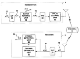
FIG. 1 is a block diagram illustrating an exemplary wireless multi-user communication system in which multiple transmitters communicate with multiple receivers through a wireless communication channel.
-
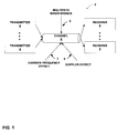
FIG. 2 is a block diagram illustrating in further detail one embodiment of a transmitter and a receiver within the multi-user communication system of FIG. 1.
-
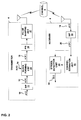
FIG. 3 is a block diagram illustrating an example embodiment of a block forming unit within the transmitter of FIG. 2.
-
FIG. 4A illustrates an example arrangement of symbols stored within a symbol buffer in array format.
-
FIG. 4B illustrates an example stream of symbols generated by a block forming unit within the transmitter.
-
FIG. 5 illustrates an example matrix which models the wireless communication channel of FIG. 2.
-
FIG. 6 is a flowchart illustrating an example mode of operation of the multi-user wireless communication system of FIG. 2 in which a receiver performs channel estimation on a wireless communication signal in accordance with the techniques described herein.
-
FIGS. 7-12 are graphs illustrating exemplary performance estimates of the channel estimation techniques described herein.
DETAILED DESCRIPTION
-
Throughout the Detailed Description bold upper letters denote matrices, bold lower letters stand for column vectors, (●)T and (●)H denote transpose and Hermitian transpose, respectively; (●)• denotes conjugate and (●)† denotes the matrix pseudoinverse. E[●] stands for expectation with respect to all the random variables with the brackets, ┌●┐ and └●┘ represent the integer floor and integer ceiling, respectively; ★ and † represent convolution and Kroenecker's product, respectively; [A]k,m denotes the (k, m)th entry of a matrix A, tr(A) represents the trace of matrix A, and [x]m denotes the mth entry of the column vector x, and diag[x] stands for a diagonal matrix with x on its main diagonal
-
FIG. 1 is a block diagram illustrating a multi-user wireless communication system 2 in which multiple transmitters communicate with multiple receivers through time- and frequency-selective wireless communication channel 8. In general, the invention provides techniques for forming estimates of channel 8 at receivers 6. In particular, training symbols are utilized in a manner that suppresses any effects of multi-path interference 5, carrier frequency offsets 7, and/or Doppler effects 9 that could otherwise be introduced during transmission through time- and frequency-selective channel 8. Furthermore, the structure and coding scheme of the blocks of symbols transmitted by transmitters 4 are designed so that in one embodiment, the minimum mean-square error (MMSE) of channel 8 is minimized and the average capacity is maximized.
-
In general, wireless communication channel 8 may experience frequency-selectivity when high data rates in relation to bandwidth create multipath interference 5 while carrier frequency offsets 7 and the Doppler effect 9 may cause frequency-selectivity. Carrier frequency offsets 7 can occur when a voltage controlled oscillator (VCO) of a receiver 6 is not oscillating at exactly the same carrier frequency as a VCO of a transmitter 4, while the Doppler effect 9 is typically caused by varying distances between a transmitter 4 and a receiver 6.
-
To suppress these effects, each of transmitters 4 outputs a wireless transmission signal in accordance with a block of symbols in which at least two blocks of training symbols of two or more training symbols are separated by at least one information-bearing symbol. In particular, the blocks of training symbols are designed to be separable from the information-bearing symbols at each of receivers 6 so that channel estimation is decoupled from symbol detection at each of receivers 6, thereby enabling the receivers to perform low-complexity channel estimation. Each of receivers 6 receive the wireless transmission signal and estimate time- and frequency-selective channel 8 based on the received blocks of training symbols. Symbol estimates are output based on the received information-bearing symbols and channel estimates.
-
The described techniques can work with existing block transmission formats and, therefore, is backward compatible with a number of conventional multi-user transmission formats including Code Division Multiple Access (CDMA) and Orthogonal Frequency Division Multiplexing (OFDM). The former is an example of single-carrier multiple access scheme, while the latter is a multi-carrier scheme. OFDM has been adopted by many standards including digital audio and video broadcasting (DAB, DVB) in Europe and high-speed digital subscriber lines (DSL) in the United States. OFDM has also been proposed for local area mobile wireless broadband standards including IEEE802.11a, MMAC and HIPERLAN/2.
-
The techniques described herein apply to uplink and downlink transmissions, i.e., transmissions from a base station to a mobile device and vice versa. Transmitters 4 and receivers 6 may be any device configured to communicate using a multi-user block wireless transmissions including a cellular distribution station, a hub for a wireless local area network, a cellular phone, a laptop or handheld computing device, a personal digital assistant (PDA), a Bluetooth™ enabled device and other such devices.
-
FIG. 2 is a block diagram illustrating in further detail one embodiment of a transmitter 4 and a receiver 6 within the multi-user communication system 2 of FIG. 1. In particular, FIG. 2 illustrates exemplary embodiments of transmitter 4 and receiver 6 communicating over time- and frequency-selective, also referred to as “doubly-selective”, wireless communication channel 8.
-
Generally, receiver 6 corresponds to a particular user, and performs channel estimation of a wireless transmission signal output by transmitter 4 over doubly-selective channel 8. In particular, receiver 6 performs channel estimation in accordance with blocks of symbols formed by transmitter 4 by the insertion of one or more blocks of training symbols within each block of information-bearing symbols. More specifically, each information-bearing symbol s(i) 10 is of a serial stream of information-bearing symbols is input into serial to parallel converter 11 which parses Ns information-bearing symbols into blocks of information-bearing symbols s(k) 12. Two arguments, n and k, are used herein to described the serial index i=kN+n for n ([0, N−1] and the (n+1)st entry of the kth block is denoted as [s(k)]n:=s(kN+n). Consequently, each block of information-bearing symbols s(k):=[s(kNs), . . . , s(kNs+Ns−1]T 12 includes Ns information-bearing symbols. Block forming unit 13 forms a block of symbols u(k) 16 by inserting a block of training symbols b(k):=[b(kNb), . . . , b(kNb+Nb−1]T 14 into blocks of information bearing symbols 10, as will be described in greater detail below. Each block of training symbols b(k) 14 includes Nb training symbols which are known to transmitter 4. Consequently, each block of symbols u(k) [u(kN), . . . , u(kN+N−1]T 16 includes N=Ns+Nb symbols. Parallel to serial converter (P/S) 15 parses the blocks of symbols 16 into a serial stream of symbols from which pulse shaping unit 17 forms a wireless transmission signal for transmission through doubly-selective channel 8.
-
Generally, the time-varying impulse response of channel that includes transmit-receive filters as well as doubly-selective propagation effects, multipath interference 5, carrier frequency offset 7, and the Doppler effect 9, can be represented by h(t; τ). With H(f; τ) representing the Fourier Transform of h(t; τ), the delay-spread is denoted as τmax and the Doppler-spread is represented as fmax. The delay-spread and Doppler-spread are defined as the thresholds for which |H(f; τ)|≈0, for |τ|>τmax or, |f|>fmax. The sampling period at receiver 6 is equal to the symbol period Ts and the blocks of symbols 16 are transmitted over channel 8 during time intervals of NTs seconds. Over each time interval of NTs seconds, for example the kth, we represent h(t; τ) for tε[kNTs, (k+1)NTs] using: a) Q+1 coefficients {hq}q=0 Q that remain invariant per block, but are allowed to change with k, i.e. the coefficients are invariant during transmission of a block of symbols, but are allowed to change from block to block, and b) Q+1 Fourier bases that capture the time variation, but are common for all k. Using the serial index i, the block index can be defined k:=└i/N┘. As a result, the discrete-time baseband equivalent model of channel 8 can be represented according to equation (1) where ωq:=2π(q−Q/2)/N, L:=└τmax/Ts┘, and Q:=2┌fmaxNTs┐.
Because both τmax and fmax can be measured experimentally, it is assumed that τmax, fmax, and thus L and Q, are bounded, known, and satisfy 2 fmaxτmax<1.
-
The product 2 fmaxτmax is known as the delay-Doppler spread factor and plays an important role in estimating double-selective channels. Underspread systems satisfy 2 fmaxτmax<1, which can be viewed as bounding the channel's degrees of freedom and renders estimation well-posed. For example, most ionospheric- and tropospheric-scattering channels as well as other radio channels give rise to underspread channels.
-
Per block of N symbols, the basis expansion model (BEM) of equation (1) can be viewed either as deterministic or, as the realization of a stochastic process with random coefficients hq(└i/N┘; l). When transmissions experience rich scattering and no line-of-sight is present, the central limit theorem can be applied to validate the following assumption when the BEM is viewed as a stochastic process with random coefficients. It is assumed that the BEM coefficients hq(└i/N┘; l) are zero mean, complex Gaussian random variables with variance σq,l 2.
-
The BEM offers a parsimonious finite-parameter representation of doubly-selective channels and was originally introduced in G. B. Giannakis and C. Tepedelenlio{haeck over (g)}lu, “Basis Expansion Models and Diversity Techniques for Blind Identification and Equalization of Time-Varying Channels” Proceedings of the IEEE, pp. 1969-1986, November, 1998, M. K. Tsatasanis and G. B. Giannakis, “Equalization of Rapidly Fading Channels: Self-Recovering Methods,” IEEE Transactions on Communications, vol. 44, no. 5, pp. 619-630, May 1996, and M. K. Tsatsanis and G. B. Giannakis, “Modeling and Equalization of Rapidly Fading Channels,” International Journal of Adaptive Control and Signal Processing, vol. 10, pp. 159-176, May 1996.
-
Therefore, the ith received sample y(i) 18 can be written according to equation (2) where w(i) is additive white Gaussian noise (AWGN) with mean zero and variance σw 2.
Serial to parallel converter 19 converts a serial stream ofy(i)s 18 into N×1 blocks y(k):=[y(kN), y(kN+1), . . . , y(kN+N−1]T 20. Selecting N≧L, the matrix-vector counterpart of equation (2) can be written according to equation (3) where w(k):=[w(kN), w(kN+1), . . . , w(kN+N−1]T, while H(k) and Hibi(k) are N×N upper and lower triangular matrices with entries [H(k)]n, m=h (kN+n; n−m), and [Hibi(k)]n, m=h(kN+n; N+n−m) for n, m=1, . . . , N.
y(k)=H(k)u(k)+H ibi(k)u(k−1)+w(k) (3)
The second term on the right hand side (r.h.s) of equation (3) captures the interblock interference (IBI) that emerges due to the channel delay-spread. It is important to note that all the channel taps are time-dependent and H(k) as well as Hibi(k) are not Toeplitz matrices.
-
Because the channel estimation coefficients hq(└i/N┘; l) in equation (1) are time invariant over NTs seconds, channel estimation unit 21 performs channel estimation every N symbols. In other words, channel estimation unit 21 performs channel estimation on a block-by-block basis. In order to enable low-complexity block-by-block processing, the IBI is removed across received blocks, but also within each received block. IBI can be removed by introducing redundancy at transmitter 4 by inserting a cyclic prefix and then discarding the “channel-contaminated” redundant symbols at receiver 6, or by inserting guard zeros per transmitted block. The latter is adopted in transmitter 4 and each block u(k) 16 satisfies condition 1.
-
- Condition 1 Each block of training symbols u(k) 16 has the form [{overscore (u)}T(k)01×L]T where the (N−L)×1 vector {overscore (u)}(k) contains Ns information-bearing symbols and Nb≧L≧0 training symbols.
The L trailing zeros in u(k) are viewed as part of the block of training symbols b(k) 14. Because Hibi(k)u(k−1)=0, the design of u(k) substantially eliminates IBI. Block forming unit 13 forms blocks of symbols u(k) 16 according to equation (4) so that a block of training symbols b(k) 14 is inserted adjacent to each block of information-bearing symbols s(k) 12. The operation of block forming unit 13 is described in greater detail in FIG. 3.
u(k)=[s 1 T(k),b 1 T(k), . . . , s P T(k),b P T(k)]T ,∀k (4)
In accordance with equation (4), block forming unit 13 groups consecutive information-bearing symbols and training symbols in sub-blocks sp(k) and bp(k) with lengths Ns,p and Nb,p, respectively. Note that these parameters satisfy Σp=1 PNs,p=Ns, Σp=1 PNb,p=Nb, and Ns+Nb=N.
-
Because blocks of training symbols 14 have Nb≧L and the last L entries are zeros, the input-output relationship of equation (3) can be rewritten according to equation (5).
y(k)=H(k)u(k)+w(k) (5)
Channel estimation unit 21 forms an estimate of H(k), Ĥ(k), based on y(k) 20 and the blocks of training symbols 14 in the transmitted signal. Symbol detection unit 23 outputs estimates ŝ(i) 24 of the recovered information-bearing symbols based on the channel estimate Ĥ(k). Channel estimation is decoupled from symbol detection at receiver 6 because of the separable structure of u(k) in equation (4). Equation (4) also enables separation of each received block y(k) 20 into two different types of received sub-blocks, yb(k) and ys(k). yb(k) depends only on H(k) and {bp(k)}p=1 P whereas ys(k) depends on H(k), {sp(k)}p=1 P, and {bp(k)}p=1 P. The block index k is omitted for brevity in the following analysis for channel estimation and symbol detection because the analysis is based on a single block. Consequently, the input-output relationship of equation (5) is rewritten according to equation (6) where Dq:=diag[1, ejω q , . . . , ejω q (N−1)], and Hq is a lower triangular Toeplitz matrix with first column [hq(0), . . . , hq(L), 0, . . . , 0]T.
Corresponding to the separation of y to ys and yb, the channel matrix H can be split into three matrices, Hs, Hb, and {overscore (H)}b. Each of the three matrices is constructed from sub-blocks of H and illustrated in detail in FIG. 5. As a result of the separation of y, two input-output relationships are given in equations (7) and (8) for ys and yb respectively, where s:=[s1 T, . . . , sP T]T, b:=[b1 T, . . . , bP T]T, {overscore (b)} includes the first L and last L entries of bp for all p, while ws and wb represent the corresponding noise vectors.
y s =H s s+{overscore (H)} b {overscore (b)}+w s (7)
y b =H b b+w b, (8)
The term {overscore (H)}b{overscore (b)} captures the interference of the blocks of training symbols to their respective adjacent blocks of information-bearing symbols.
-
In order to perform channel estimation we start from the input-output relationship of a block of training symbols given in equation (8). Based on equation (6) and the structure of Hs, Hb, {overscore (H)}b, yb can be written according to equation (9) where yp b:=Hp bbp+wp b, ∀pε[1, P], with Hp b given below, and np is the index of the first element of yp in y, and wb=[(w1 b)T, . . . , (wP b)T]T is the corresponding noise block.
Consequently, when Nb,p≦L, the matrix Hp b disappears and bp does not contain sufficient training symbols for channel estimation. Therefore, the following condition is needed.
-
- Condition 2 The length of each block of training symbols bp is at least L+1; i.e. Nb,p≧L+1, ∀pε[1,P].
-
Observing the dimensionality of Hp b, it can be deduced that out of the Nb training symbols transmitted, Nb−PL training symbol-dependent observations without interference from the unknown information-bearing symbols are received. Because (Q+1)(L+1) unknown coefficients, to guarantee uniqueness in estimating the channel using linear equations, the total number of training symbols is given in equation (10).
N b ≧PL+(Q+1)(L+1) (10)
Therefore, the minimum number of training symbols Nb for estimating doubly-selective channel 8 is L+(Q+1)(L+1) when P=1. Selecting P=1 corresponds to preamble-based training. From a bandwidth efficiency point of view, this method is desirable. However, preamble-based training is not optimal when considering mutual information based on estimated channels. The following analysis examines this tradeoff.
-
Using equation (9) which is based on equation (1), we can write Hp b:=Σq=0 QDq,p bHq,p b where Hq,p b and Dq,p b are corresponding sub-matrices from Dq and Hq in equation (6). Substituing Hp b into equation (9) we obtain equation (11).
Due to the commutativity between a Toeplitz, i.e. convolution, matrix product with a vector, Hq,p bbp=Bphq, where Bp is an (Nb,p−L)×(L+1) Toeplitz matrix given by equation (12) with bp,n denoting the (n+1)st entry of bp, hq is given by equation (13), and Hp b is given by equation (14).
Thus, the input-output relationship in equation (11) can be rewritten according to equation (15) where Φb is given in equation (16) and h is given in equation (17).
y b=Φb h+w b (15)
h:=[h0 T . . . hQ T]T (17)
-
Relying on the Wiener solution of equation (15) yields the linear MMSE (LMMSE) channel estimator given in equation (18). Equation (18) requires the channel covariance matrix Rh:=E[hhH] to be known at receiver 6.
-
Defining the channel error as {tilde over (h)}:=h−ĥ, the correlation of the channel error can be expressed according to equation (19) and the mean square error of the LMMSE can be expressed according to equation (20).
-
From the definition of Φb in equation (16), it clear that the placement of training symbols within the transmission signal affect Φb and consequently σ{overscore (h)} 2. In the following analysis the following assumption is made.
-
- Assumption 3 It is assumed that the channel coefficients hq(l) are independent, i.e. Rh is a diagonal matrix with trace tr(Rh)=1.
This assumption does not affect the optimality of the design of the blocks of training symbols developed herein because no channel state information is assumed to be known at transmitter 4.
-
It can be shown that σ{overscore (h)} 2 in equation (20) is lower bounded by the equality given in equation (21) where the equality holds if and only if Φb HΦb is a diagonal matrix.
Therefore, the following condition is required to attain MMSE of the channel:
-
- Condition 3 For a fixed number of training symbols Nb and information-bearing symbols Ns, the blocks of training symbols are inserted so that the matrix Φb HΦb is diagonal.
-
Although the estimate of channel 8 has been defined in equation (18) and conditions 1-3 are defined, additional parameters of the training symbols affect the performance of communication system 2. The performance of communication system 2 is affected by the performance of the channel estimator given in equation (18), the effective transmission rate η=Ns/N, the mutual information, as well as bit error rate (BER). In the following analysis the placement, power allocation, and number of training symbols are selected by optimizing an average capacity bound of channel 8. However, it will first be shown that optimizing this average capacity bound also minimizes the MMSE of channel 8.
-
Because it is not easy to evaluate the average capacity of an unknown random channel that is to be estimated, an upper and a lower bound will be derived instead. In order to design optimal parameters for the training symbols, the lower bound of the capacity is maximized and the upper bound is viewed as a benchmark for the maximum achievable rate.
-
The total transmit-power per block of
symbols 16 is denoted as
while the power allocated to the information bearing symbols within
block 16 is denoted
s, and the power allocated to the training symbols within
block 16 is denoted
b. Before considering optimal power allocation, assume that
s and
b are fixed and allow Ĥ to be any estimator of H given in equation (6). Because training symbols b do not convey information, for a fixed power
s:=: E[∥s∥
2], the conditional mutual information between transmitted information-bearing symbols and received symbols in equation (7) is denoted as I(y
s; s|ĥ) for each realization of H. The channel capacity averaged over the random channel H is defined according to equation (22) where p
s(•) denotes the probability function of s.
-
Assuming that the channel estimation is perfect, i.e. Ĥ≡H. the average capacity is defined according to equation (23).
From equation (7) it is known that ys=Hss+{overscore (H)}b{overscore (b)}+ws, where {overscore (H)}b is the corresponding channel matrix for {overscore (b)}. Because {overscore (H)}b and {overscore (b)} in equation (7) are known in the ideal case, by defining y′s:=ys−{overscore (H)}b{overscore (b)}, it can be verified that I(ys; s|h)=I(y′s; s|h). In order to maximize I(y′s; s|h), lemma 1 is established.
-
- Lemma 1 If the block of information-bearing symbols s is Gaussian distributed, then the mutual information I(y′ss|h) is maximized. Furthermore, the capacity upper bound in equation (23) can be expressed according to equation (24).
Although s is generally non-Gaussian, if Ns is sufficiently large and s is channel coded or linearly precoded, the s will be approximately Gaussian. Thus, in the following analysis assumption 4 is made.
- Assumption 4 It is assumed that the block of information-bearing symbols s is zero-mean with variance Rs={overscore ()}SIN s , and {overscore ()}S:= S/NS.
The covariance Rs is selected as such because there is no CSI at transmitter 4 and thus non-uniform power-loading has no basis. It is important to note that {overscore (C)} in equation (23) is an upper bound on the average channel capacity with estimated channels because it expresses the ideal channel capacity without channel estimation error.
-
In the following analysis the lower bound on average channel capacity with LMMSE channel estimation is derived. It is now assumed that the estimate of H is imperfect and Ĥ
s is defined as the estimate of H
s and {overscore (Ĥ)}
b is defined as the estimate of {overscore (H)}
b. Because {overscore (b)} and {overscore (Ĥ)}
b are known, Ĥ
b{overscore (b)} is subtracted from y
s. Thus, is defined according to equation (25).
y′ s :=y s −{overscore (Ĥ)} b {overscore (b)}=Ĥ s s+(
H s −Ĥ s)
s+(
{overscore (H)} b −{overscore (+E,cir )} b)
{overscore (b)}+w s (25)
Using equations (7) and (25) it can be verified that I(y′
s; s|Ĥ
s)=I(y
s; s|Ĥ
s). We then define the error of channel matrices as {tilde over (H)}
s:=H
s−Ĥ
s, {tilde over (H)}
b:={overscore (H)}
b−{overscore (Ĥ)}
b, and v:={tilde over (H)}
ss+{tilde over (H)}
b{overscore (b)}+w
s. In general, v is non-Gaussian distributed with correlation matrix R
v:=E[vv
H] given by equation (26) where E[{tilde over (H)}
ss{overscore (b)}{tilde over (H)}
s H]=0 because s is assumed to be zero-mean Gaussian with covariance R
s.
R v={overscore (
)}
s E[{tilde over (H)} s {tilde over (H)} s H ]+E[{tilde over (H)} b {overscore (bb)} H {tilde over (H)} b H]+σ
w 2 I N s +LP (26)
Because of the non-Gaussianalty of v, it is difficult to obtain a closed form of the average capacity.
Lemma 2 proposes a lower bound of average channel capacity C defined in equation (22).
-
- Lemma 2 When the block of information bearing symbols s is Gaussian distributed with fixed power s, the average capacity C in equation (22) is lower bounded according to equation (27).
A lower-bound which is looser than the r.h.s. of equation (27), but easier to handle is given in equation (28). By substituting Rs={overscore ()}sIn s into equation (27), equation (28) can be obtained.
The r.h.s. of equation (28) offers a lower bound on the average capacity of doubly-selective channels. Transmitter 4 selects the parameters of the training symbols so that C of equation (28) is maximized. The selected parameters of the training symbols improve both the channel estimator of equation (18) and the associated MMSE of equation (20). The lower bound C of equation (28) and the channel MMSE of equation (20) are linked. In order to establish this link, Lemma 3 and Lemma 4 are established.
- Lemma 3 Assume conditions 1-3 hold, assumptions 1-4 are true, the power of each information-bearing symbol is {overscore ()}s, and the lengths of Nb,p and Ns,p are fixed. Then, maximizing C as given in equation (28) is equivalent to minimizing Rv inn equation (26) at high signal-to-noise ratio (SNR).
Although Rv depends on the MMSE of the channel
as defined in equation (20), the dependence is not explicit. Lemma 4 provides an explicit relationship between Rv and
- Lemma 4 Consider a fixed number of training symbols Nb adhering to condition 1 and condition 2. Among all designs of bp which satisfy condition 3 and lead to identical R{overscore (h)}, the design which satisfies Nb,p≧2L+1 and has the first L and the last L entries of bp, ∀pε[1, P] equal to zero, achievs the minimum Rv.
Based on Lemmas 3 and 4, condition 2 is modified to form condition 2′.
- Condition 2′ Each block of training symbols bp:=[0L T{overscore (b)}L T0L T]T, ∀pε[1, P] with the length of {overscore (b)}p, N{overscore (b)},p≧1.
Note that the L zeros between the blocks of information-bearing symbols sp, and the length of the blocks of training symbols {overscore (b)}p eliminate the inter-sub-block interference. Condition 2′ implies that Nb,p≧2L+1. Proposition 1 establishes the link between the channel MMSE in equation (20) and the lower bound C in equation (28) based on the assumptions and design conditions currently introduced.
- Proposition 1 Assume assumption 1-4 and conditions 1-3 hold true. If Ns,p>>2L, ∀p, then for fixed Ns,p and Nb,p the minimization of the channel MMSE in equation (20) is equivalent to the maximization of C in equation (28).
In order to prove proposition 1, we define ψq,l:=E[{tilde over (h)}q(l){tilde over (h)}q *(l)], and rely on condition 3 to express the correlation matrix in equation (16) according to equation (29).
R {tilde over (h)} =diag└ω 0,0, . . . , ψQ,L┘ (29)
Because Dq is known, {tilde over (H)}s:=Hs−Ĥs is a block-diagonal matrix as illustrated in greater detail in FIG. 3. Additionally, because E[{tilde over (h)}q1(l1){tilde over (h)}q2 *(l2)]=0, ∀ l1≠l2, or ∀q1≠q2, the correlation matrix of {tilde over (H)}s can be written according to equation (30) where {tilde over (H)}s q is defined according to equation (31) and {tilde over (H)}q,p s is a lower triangular Toeplitz matrix with first column [{tilde over (h)}q(0), . . . , {tilde over (h)}q(L), 0, . . . , 0]T.
From equation (29) we can detail equation (30) according to equation (32).
Equation (32) shows that the correlation matrix of {tilde over (H)}q s, and thus {tilde over (H)}s, is a diagonal matrix. In addition, selecting Ns,p>>2L the correlation matrix of {tilde over (H)}s can be approximated according to equation (33).
Considering condition 2′ and condition 3, the correlation matrix Rv in equation (26) can then be expressed according to equation (34).
It can be deduced from equation (34) that as the channel MMSE σ{overscore (h)} 2 decreases, Rv decreases and from Lemma 3, it is inferred that C h increases accordingly. In other words, better channel estimation implies higher average capacity.
-
In the following analysis the link between the LMMSE channel estimation with the maximum lower bound of the average channel capacity is used to design optimal training parameters. In particular, the placement, number, and power of the training symbols are selected.
-
Because the LMMSE channel estimator of equation (18) was adopted the analysis begins from equations (18)-(20). First, Φ
b, which is dependent on B
p as per equation (12), is designed so that σ
{overscore (h)} 2 is minimized subject to the power constraint on the totally power of training symbols. As a result of
condition 3, the r.h.s. of equation (20) satisfies the equality given in equation (35) where the second equality holds if and only if Φ
b HΦ
b=
bI.
Based on the structure of Φ
b it can be inferred that two conditions given in equations (36) and (37) need to be fulfilled.
It is difficult to obtain a general placement of training symbols satisfying equations (36) and (37).
Lemma 5 provides further insight as to the optimal placement of training symbols.
-
- Lemma 5 For a fixed number of training symbols Nb, information-bearing symbols Ns>2L, power s, and number of sub-blocks P per bock. If Ns is an integer multiple of P, then equally long information sub-blocks maximize the lower bound of capacity C. The length of the sub-blocks of information-bearing symbols is {overscore (N)}s:=Ns/P.
Proposition 2 provides sufficient conditions to achieve placement satisfying equations (26) and (37).
- Proposition 2 Assume assumptions 1-4 hold true. For fixed s and b the following placement is optimal is optimal: all sub-blocks of information-bearing symbols have identical block lengths, i.e. Ns,p={overscore (N)}s, ∀p; the blocks of training symbols have identical structure [0L Tb0L T]T, ∀p, and are equi-powered with b={overscore (ρ)}b:= b/P.
-
In order to prove proposition 2, we first confirm the conditions 1-3 hold true. According to proposition 1 we will verify that C is maximized and check whether σ{tilde over (h)} 2 is also minimized.
-
If ∀p, N{overscore (b)},p=1, and Bp={square root}{square root over (()}{overscore (ρ)}b)IL+1, then Bp HBp={overscore (ρ)}bIL+1. Therefore,
is a diagonal matrix. Thus, condition 1 is satisfied. Substituting Bp into the left hand side (l.h.s.) equation (37) results in the equality given in equation (38) where {overscore (D)}q2,p includes the first L+1 columns and the first L+1 rows of Dq,p.
Because the BEM frequencies are equi-spaced, it follows that Ns,p={overscore (N)}s and Nb,p=2L+1. By defining the difference between two consecutive BEM frequencies as wq−wq−1=2π/N we obtain equation (39).
Thus, the transmitted block length should be {overscore ((N)}s+2L+1)P. Thus, equation (40) implies that that the proposed placement satisfies equation (37) and condition 3 which is defined according to equation (41).
Φb HΦb=ρbI(q+1)(L+1) (41)
The MMSE in equation (35) has thus been achieved and C has been maximized per proposition 1.
Using proposition 2, the structure of the block of symbols is given according to equation (42) and we have obtained that Nb,p=2L+1. In order to satisfy the equality in equation (10), the number of sub-blocks of training symbols per block of symbols transmitted must satisfy P(Q+1).
u=[s 1 T0L Tb0L T . . . sP T0L TbL T]T, b={square root}{square root over (ρ)}b (42)
-
Proposition 3 states the relationship between the number of training symbols per sub-block and the performance of communication system 2.
-
Proposition 3. If the powers
s and
b are fixed, the number of sub-blocks P≧(Q+1), and the number of training symbols per block of training symbols N
b,p≧(2L+1), then as N
b,p •,p and/or P increase,
C decreases.
-
Note that when Nb,p<2L+1 and P<Q+1, the minimum R, in equality (35) cannot be guaranteed as per Lemma 4.
-
In the following analysis, we derive the channel MMSE and average capacity with optimal placement of training symbols. Equation (42) gives the optimal placement of training and information-bearing symbols per block u(k) 16 that maximizes C and minimizes the LMMSE channel estimation error. Using the Gaussian channel assumption, the latter coincides with the channel MMSE, and thus provides a benchmark for estimation performance when Rh is known at receiver 6. In particular, the following analysis derives this benchmark MMSE for the optimal placement of training and information-bearing symbols when Rh is known, and also when Rh is unknown. Furthermore, a closed form of the maximum lower bound on average channel capacity C when the optimum placement of symbols given in equation (42) is used. It is important to note that this allows the optimal average-rate possible through doubly-selective fading channels to be predicted when optimal training is adopted for channel estimation.
-
If the channel coefficients are independent, but not necessarily identically distributed, substituting equation (41) into equation (19) allows Rh to be expressed according to equation (43) where σQ,L 2 is the variance of hq(l). The tr(R{overscore (h)}) benchmarks the performance of channel estimation unit 21 when the channel coefficients are independent with known variances.
-
For channel estimation, the structure of the blocks symbols given in equation (42) is optimal. Note that for a fixed
b, when N
b,p=2L+1 the optimal tr(R
{overscore (h)}) will not decrease so long as P(Q+1) because the lower bound of tr(R
{tilde over (h)}) in equation (35) holds for any P. On the other hand, as
b increases, R
{tilde over (h)} will decrease monotonically. However, the mutual information should also be taken into account. Because
is fixed, the more power allocated to the training symbols the less power is available to be allocated to the information-bearing symbols. Furthermore, as P increases, the bandwidth efficiency decreases. In the following analysis the optimal design of P and power allocation are derived. However, we first summarize the conditions implied by
proposition 2 in
condition 4, and rewrite
C based on these conditions.
-
- Condition 4 Select the length of the block of symbols u(k) equal to N as a multiple of P and design each u(k) according to equation (42).
-
Using equation (43), the correlation matrix of {tilde over (H)}s can be simplified. Because Ns,p={overscore (N)}s, it can be verified that E└{tilde over (H)}q,p s(q,p s)H┘ does not depend on the index p. Defining Ψq:=E└{tilde over (H)}q,p s({tilde over (H)}q,p s)H┘, equations (44) and (45) can be written.
E└{tilde over (H)} q s({tilde over (H)} q s)H ┘=I P{circumflex over (×)}Ψq (44)
Because of the zeros surrounding each training symbol in equation (42), {overscore (b)}=0. Thus, the correlation matrix Rv can be expressed according to equation (46).
Using condition 4, we have equation (47) and from equation (47) equation (48) can be written.
Because
the normalization factor for E└{tilde over (H)}q s({tilde over (H)}q s)H┘ can be obtained according to equation (49).
Consequently, the normalized channel matrix can be expressed according to equation (50).
Ĥ p s=σĤ {overscore (Ĥ)} p s ,∀p (50)
Thus, it can be deduced that the lower bound on average channel capacity is given according to equation (51).
Equation (51) relates the lower bound C with the number of sub-blocks P and the signal power {overscore (P)}s which in turn depends on the placement of the training symbols and the selected allocation of power.
-
Relying on equations (47) and (48), Lemma 6 is formed.
-
- Lemma 6 If assumption 2 holds true, then all {overscore (Ĥ)}p s have identical distribution, ∀pε[1, P].
Based on lemma 6, the lower bound on the average capacity can be expressed according to equation (52) where {overscore (Ĥ)}s is used to represent {overscore (Ĥ)}p s, ∀p.
Using the eigen-decomposition, [({overscore (Ĥ)}s({overscore (Ĥ)}s , ,)]=UΛHUH, where ΛH:=diag[λ1, . . . , λ{overscore (N)}k is an {overscore (N)}s×{overscore (N)}s diagonal matrix with eigen-values of [({overscore (Ĥ)}s({overscore (Ĥ)}s)H)] on its main diagonal, and U is a unitary matrix which contains the corresponding eigen-vectors. Proposition 1 shows that selecting N>>2L yields
Thus the lower bound on the average channel capacity can be expressed according to equation (53) where in deriving equation (53) the identity det(I+AB)=det(I+BA) for matrices A and B with matching dimensions was used.
Note that the λk's are not identically distributed, in general. This leads to a looser lower bound on the average capacity.
-
The effective SNR is defined according to equation (54).
Since {overscore (N)}sP=N−P(2L+1), the looser bound is given by equation (55) where λmin=min{λk}k=1 {overscore (N)} s .
-
Proposition 2 establishes that the optimal number of pilots per sub-block is Nb,p=2L+1(N{overscore (b)},p=1). In the following analysis, the optimal number of blocks of training symbols bp per transmission block is considered, i.e. how often the training sub-blocks should be inserted to maximize average channel capacity.
-
In order to obtain the optimal number of blocks P in equation (55), for fixed N, ρs and ρb, P is treated as a continuous variable. We can then differentiate C a with respect to P to obtain equation (56) where in the second step, the inequality ln(1+χ),∀χ]0 was used. Because ∂C a/∂P<0, to achieve the maximum lower bound on the channel capacity, P should be taken to be as small as possible.
Moreover, in order to guarantee the condition in equation (10) with Nb,p=2L+1, we must select P≧Q+1. This implies that the optimal number of sub-blocks is P=Q+1. Thus, we have established the following proposition.
-
- Proposition 4 Consider transmission of information blocks of length N through time- and frequency-selective random channel 8 modeled as in (1). If conditions 1-4 are satisfied, and a fixed power is allocated to the training symbols, then the lower bound given in (55) is maximized if and only if the number of blocks of training symbols bp is P=Q+1.
Although this result is derived for the looser bound C a in equation (55), it is also true for equation (51). An intuitive explanation is that as P increases, the performance of channel estimation does not improve, but the number of information symbols descreases causing C to decrease as well. When P≦Q+1, the mutual information suffers from unreliable channel estimation, since the condition in equation (10) is not satisfied. Note that now the number of pilot symbols is (Q+1)(2L+1), which is the smallest possible since P=Q+1.
-
Thus far, the total power P has been fixed. Based on this, it has been derived that the training symbols must be equi-powered and equi-spaced. In the following analysis the optimal allocation of the total power between information-bearing symbols and training symbols is derived.
-
The total transmit-power per block of symbols is P=Ps+Pb where Ps:=αP, and thus Pb=(1−α)P for some αε(0,1). From equation (49), it can be verified that
where σ{overscore (h)} 2 is given according to equation (57).
Thus, the effective SNR in equation (54) can be rewritten according to equation (58).
It is difficult to find an optimal power allocation factor α which does not depend on any CSI directly from equation (58), because σ{tilde over (h)} 2 depends on σq,l 2. Therefore, the following three cases are considered: low SNR, high SNR and identical distributed channel taps.
-
For low SNR, i.e. (σw 2>>(1−α)Pσq,l 2), equation (57) can be simplified as
Substituting this result into equation (58) gives equation (59).
-
The optimal power allocation factor α can be obtained by differentiating ρeff with respect to the variable α and finding the zero of this differential. Note that α belongs to the range (0,1). Thus, for this case, α is defined according to equation (60).
αlow=½ (60)
-
For high SNR, i.e. ((1−α)Pσq,l 2>>σw 2) equation (57) gives
Thus, the effective SNR in equation (54) can be rewritten according to equation (61).
-
After differentiating ρeff with respect to α, it is found that at high SNR, the optimal power allocation factor is given according to equation (62).
When the SNR P/((L+1)(Q+1)σw 2)→∞, the optimal power allocation factor reduces to equation (63).
-
For identical distributed channel coefficients, i.e. (σ q,l 21/(L+1)(Q+1))), equation (57) can be rewritten as
Substituting this result into equation (58) results in the optimal power allocation factor to be given according to equation (64).
Similar to the previous two cases of low and high SNR, after differentiating ρeff with respect to α, the optimal power allocation factor is given according to equation (65) where β=1+(L+1)(Q+1)σw 2/ρ.
When P/((L+1)(Q+1)σw 2)→∞,αlid converges to α∞ in (63). When P/((L+1)(Q+1)σw 2)→αlid→½.
-
Proposition 5 states how the optimal power allocation factor is selected.
-
- Proposition 5 Assume that conditions 14 hold true, and that the SNR is sufficiently high. Using assumptions 1-4 and for a fixed {overscore (N)}s, the lower bound on average capacity is maximized with the MMSE channel estimator when the power allocation factor α is given by (60), (62), or (65).
-
Thus, techniques for performing channel estimation which minimize the channel MMSE and maximize the average capacity have been described herein.
-
FIG. 3 is a block diagram illustrating an example embodiment of block forming unit 13 (FIG. 2) within transmitter 4. In this embodiment, block forming unit 13 comprises a training symbol insertion unit 30 that inserts blocks of training symbols 14 within blocks of information-bearing symbols 12 according to equation (42). Symbol buffer 32 receives and stores the symbols in array fashion in which the symbols are written into the symbol buffer in a row-wise fashion, with each row storing Q+1 symbols. The structure of symbol buffer 32 is described in greater detail in FIG. 4. Symbol interleaver 34 outputs symbol blocks 16 by reading the symbols from symbol buffer 32 in a column-wise fashion.
-
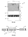
FIG. 4A illustrates an example arrangement of symbols within symbol buffer 32. In this arrangement, the information-bearing symbols are organized as an {overscore (N)}s×(Q+1) matrix 40 followed by L×(Q+1) zero symbols 42, Q+1 training symbols 44, and another L×(Q+1) zero symbols 46. Each column of symbol buffer 32 denotes a read-out operation producing blocks of symbols 16, which are described in greater detail in FIG. 4B, while each row denotes a write-in operation.
-
FIG. 4B illustrates an example stream 50 of blocks of symbols generated by block forming unit 13 within transmitter 4. In particular the stream 50 of symbol blocks is generated by reading symbol buffer 32 in a column-wise fashion. The structure of stream 50 satisfies equation (42) with blocks of information-bearing symbols 52 separated by blocks of training symbols, each block of training symbols having Q+1 training symbols 54, which may be zero or non-zero symbols, with the first L and last L training symbols, 56 and 58 respectively, being zero symbols.
-
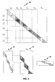
FIG. 5 illustrates example matrix H 60, which models the wireless communication channel of FIG. 2, and from which matrices H, 62, {overscore (H)}b 64, H b 66 are constructed. Each of matrices H s 62, {overscore (H)}b 64, H b 66 are constructed from sub-blocks of H corresponding to vectors s, {overscore (b)}, and b respectively.
-
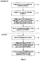
FIG. 6 is a flowchart illustrating an example mode of operation of multi-user wireless communication system 2 in which receiver 6 performs channel estimation on a wireless communication signal in accordance with the currently described techniques.
-
Generally, transmitter 4 forms a block of N, information-bearing symbols s(k) 12 (step 70) and forms Q+1 blocks of Nb training symbols b(k) 14 (step 72). In particular, bp(k) 14 is formed according to lemma 4 with Nb,p>2L+1 training symbols, of which the first L and the last L training symbols are zeros.
-
After forming the blocks of information-bearing symbols and blocks of training symbols, transmitter 4 forms a block N of symbols by inserting Q+1 blocks of training symbols within a block of N, information-bearing symbols (step 74). In some embodiments, transmitter 4 inserts Q+1 blocks of training symbols in accordance with equation (42) so that each block of training symbols is equally spaced by {overscore (N)}s=Ns/(Q+1) information-bearing symbols.
-
Transmitter 4 then outputs a wireless transmission signal from the block of N symbols over doubly-selective wireless communication channel 8 (step 76). Transmitter 4 allocates equal power Ps to each block of information-bearing symbols and also allocates equal power {overscore (P)}s to each information-bearing symbol with a block of information-bearing symbols. Similarly, transmitter 4 also allocates each block of training symbols equal power Pb and also allocates equal power {overscore (P)}b to each training symbol within a block of training symbols. Furthermore, in order to maximize the average channel capacity, the total transmit-power allocated to the information-bearing symbols per block of symbols and the total transmit-power allocated to the training symbols per block of symbols is Ps=αP and Pb=(1−α)P respectively, where a is defined according to equations (60), (62), and (65) for low SNR, high SNR, and identical distributed channel coefficient transmissions, respectively.
-
Receiver 6 receives the wireless transmission signal formed from the block of N symbols (step 78) and forms an estimate of communication channel 8 based on the Q+1 blocks of training symbols received per N symbols (step 80). Because of the design of the blocks of training symbols, the LMMSE estimate of communication channel given in equation (18) is minimized. Receiver 6 then outputs estimated symbols based on the estimate of communication channel 8 (step 82).
-
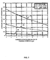
FIGS. 7-12 are graphs illustrating performance estimates of the channel estimation techniques described herein. Unless otherwise mentioned, in all test cases the transmitted block size is N=63, the number of information symbols Ns=42, and the quadrature phase-shift key (QPSK) modulation is used. The doubly-selective channel model is generated using the following parameters: carrier frequency f0=2 GHz, sampling period Ts=53.6 μs, and mobile speed νmax=160 km/hr. Thus, the maximum frequency shift is found to be fmax≈296.30 Hz. With these parameters, it is found that Q=2. The channel order is L=3. All the channel coefficients hq(l) are generated as independent, standardized, complex Gaussian random deviates. The multipath intensity profile is selected as φc(π)=exp(−0.1τ/Ts), ∀q, and the Doppler power spectrum is chosen as Sc(f)=(π{square root}{square root over (fmax 2−f2)})−1 when f≦fmax; otherwise the spectrum Sc(f)=0, ∀l. The variance of hq(l) is defined as σq,l 2:=γφc(lTs)Sc(2πq/(NTs)), where γ:=(Σl,qφc(lTs)Sc(2πq/(NTs)))−1 denotes the normalizing factor. The signal-to-noise ration (SNR) is defined as P/(N−2L(Q+1))/σw 2.
-
FIG. 7 is a graph comparing the number of the non-zero training symbols N{overscore (b)},p and the lower bound on average channel capacity given in equation (51). We let N{overscore (b)},p=N{overscore (b)}, ∀p, and adopt the other optimal parameters currently described while allowing N{overscore (b)} to vary. FIG. 7 illustrates how the capacity bound decreases monotonically as N{overscore (b)} increases for each SNR value considered, 0 dB (plot 90), 10 dB (plot 92), and 20 dB (plot 94). Furthermore, as the SNR increases, the effect of N{overscore (b)} increases. This validates the claim in Proposition 3.
-
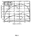
FIG. 8 is a graph comparing the power allocation factor α and the lower bound on average channel capacity given in equation (51). FIG. 8 illustrates that when α is too small (near 0), the average capacity is small since the information symbols do not have enough power to combat AWGN for each SNR value considered, 0 dB (plot 100), 10 dB (plot 102), and 20 dB (plot 104). In contrast, when α is too large (near 1), the average capacity is also small for each SNR value since the training symbols do not have enough power to provide reliable channel estimation. From equation (62), the optimal α≈0.65 in the simulations is also verified by inspecting the maximum in FIG. 7.
-
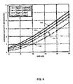
FIG. 9 is a graph comparing the currently described design with a PSAM design having {overscore (P)}b={overscore (P)}s and otherwise having parameters selected according to the currently described design. For this case, the power allocation factor is α={overscore (N)}s/(1+{overscore (N)}s)≈0.93. From Eq. (62), the optimal α≈0.65. FIG. 9 depicts the lower and upper bounds for both cases. Note that for the optimal allocation, the lower bound (plot 112) is closer to the upper bound (116) than for the equi-powered PSAM with lower bound (plot 110) and upper bound (114). Thus, optimal power allocation results in improved performance. Furthermore, the lower bound for the optimal PSAM (plot 112) is higher than that of equi-powered PSAM (plot 110) since more power is allocated for training in the optimal case. Similar reasoning explains why the upper bound of the equi-powered PSAM (plot 114) is higher than that of the optimal PSAM (plot 116).
-
FIG. 10 is a graph comparing the bit-error rate (BER) performance vs. SNR of the currently described design with a PSAM design having {overscore (P)}b={overscore (P)}s and otherwise having parameters selected according to the currently described design. It can be observed that compared with the equi-powered PSAM (plot 120), the optimal design (plot 122) gains 3 dB and 10−2. The ideal case (plot 124) with perfect channel estimates is also plotted as a benchmark. FIG. 10 shows that the SNR penalty for channel estimation error is only about 1.5 dB if we adopt the optimal α.
-
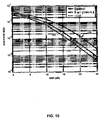
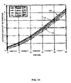
FIG. 11 is a graph comparing the average channel capacity for varying SNRs of the currently described techniques which utilize zero padding (ZP) with techniques utilizing cyclic prefix (CP) insertion, as described in S. Adireddy, L. Tong, and H. Viswanathan, “Optimal Placement of Training for Unknown Channels,” IEEE Transactions on Information Theory, vol. 48, no. 8, pp. 2338-2353, August 2002 and S. Ohno and G. B. Giannakis, “Capacity Maximizing Pilots for Wireless OFDM over Rapidly Fading Channels,” IEEE Transactions on Information Theory, 2003. The channel is frequency-selective with i.i.d. taps. The channel order L=7, and each tap is a zero mean Gaussian random variable with variance 1/(L+1). The number of information symbols per block is {overscore (N)}s=48, and the block length N={overscore (N)}s+2L+1. So for CP-based training, the CP length is L. The total power per block is fixed to P. Hence, the power ratio allocated between information symbols and training symbols for the CP-based scheme, is P({overscore (N)}s+L+1)/N. FIG. 11 depicts the average capacity bounds for both the ZP- and CP-based alternative with SNR:=P/({overscore (N)}s+1). For ZP-based training, the capacity upper (plot 130) and lower bounds (132) are plotted using (24) and (51) with Q=0. For CP-based training, the capacity upper and lower bounds, (plot 136) and (plot 134) respectively, are plotted according to the previously referenced paper authored by S. Ohno and G. B. Giannakis. FIG. 11 shows the bounds (either upper or lower) for ZP are consistently greater than those of CP, which is partially due to the power loss incurred by the CP.
-
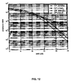
FIG. 12 is a graph comparing BER for varying SNRs of a system using the currently described techniques which utilize zero padding (ZP) with techniques utilizing cyclic prefix (CP). FIG. 12 plots the performance of both techniques using ideal channel estimates, CP (plot 140) and ZP (plot 146), and with computed MMSE channel estimates, CP (plot 142) and ZP (plot 144). The computed MMSE channel estimates are based on training symbols and use zero-forcing (ZF) equalization for symbol detection in both cases. From FIG. 12, it is observed that ZP outperforms CP at high SNR, while CP has about 2 dB advantage at BER-0.1. Additionally, from the slopes of the curves, it is observed that CP offers lower diversity order than ZP, and for both cases, the penalty for inaccurate channel state information is about 1.5 dB.
-
The described techniques can be embodied in a variety of transmitters and receivers used in downlink operation including cell phones, laptop computers, handheld computing devices, personal digital assistants (PDA's), and other devices. The devices, such as transmitter 4 or receiver 6 of FIG. 2, may include a digital signal processor (DSP), field programmable gate array (FPGA), application specific integrated circuit (ASIC) or similar hardware, firmware and/or software for implementing the techniques. If implemented in software, a computer readable medium may store computer readable instructions, i.e., program code, that can be executed by a processor or DSP to carry out one of more of the techniques described above. For example, the computer readable medium may comprise random access memory (RAM), read-only memory (ROM), non-volatile random access memory (NVRAM), electrically erasable programmable read-only memory (EEPROM), flash memory, or the like. The computer readable medium may comprise computer-readable instructions that when executed in a wireless communication device, cause the wireless communication device to carry out one or more of the techniques described herein. These and other embodiments are within the scope of the following claims.