US20050127326A1 - Liquid crystal composition, selectively reflective film and method for producing the same - Google Patents
Liquid crystal composition, selectively reflective film and method for producing the same Download PDFInfo
- Publication number
- US20050127326A1 US20050127326A1 US11/044,254 US4425405A US2005127326A1 US 20050127326 A1 US20050127326 A1 US 20050127326A1 US 4425405 A US4425405 A US 4425405A US 2005127326 A1 US2005127326 A1 US 2005127326A1
- Authority
- US
- United States
- Prior art keywords
- liquid crystal
- crystal composition
- light
- isomerization
- photoreactive chiral
- Prior art date
- Legal status (The legal status is an assumption and is not a legal conclusion. Google has not performed a legal analysis and makes no representation as to the accuracy of the status listed.)
- Abandoned
Links
- KBWJDAVGYRXZEW-UHFFFAOYSA-N C=CC(=O)OCCCCOc1ccc(C(=O)c2ccc(N)c(Br)c2)cc1.C=CC(=O)OCCCCOc1ccc(C=O)cc1 Chemical compound C=CC(=O)OCCCCOc1ccc(C(=O)c2ccc(N)c(Br)c2)cc1.C=CC(=O)OCCCCOc1ccc(C=O)cc1 KBWJDAVGYRXZEW-UHFFFAOYSA-N 0.000 description 4
- WJKHYAJKIXYSHS-UHFFFAOYSA-N Clc1ccc(-c2nc(C(Cl)(Cl)Cl)nc(C(Cl)(Cl)Cl)n2)cc1 Chemical compound Clc1ccc(-c2nc(C(Cl)(Cl)Cl)nc(C(Cl)(Cl)Cl)n2)cc1 WJKHYAJKIXYSHS-UHFFFAOYSA-N 0.000 description 4
- ITURVBNTAXNLNF-KAVXHDQVSA-N CCCCCCCCOc1ccc(C=C(C#N)C(C)=O)cc1OC.[H][C@]12OC[C@@H](C)[C@@]1([H])OC[C@@H]2C Chemical compound CCCCCCCCOc1ccc(C=C(C#N)C(C)=O)cc1OC.[H][C@]12OC[C@@H](C)[C@@]1([H])OC[C@@H]2C ITURVBNTAXNLNF-KAVXHDQVSA-N 0.000 description 3
- CYFRMHXZCCYXRL-KAVXHDQVSA-N C=CC(=O)OCCCCOc1ccc(C(C)=O)cc1.[H][C@]12OC[C@@H](C)[C@@]1([H])OC[C@@H]2C Chemical compound C=CC(=O)OCCCCOc1ccc(C(C)=O)cc1.[H][C@]12OC[C@@H](C)[C@@]1([H])OC[C@@H]2C CYFRMHXZCCYXRL-KAVXHDQVSA-N 0.000 description 2
- ORQLUDZFUZFFQO-KAVXHDQVSA-N COc1ccc(C=CC(C)=O)cc1.[H][C@]12OC[C@@H](C)[C@@]1([H])OC[C@@H]2C Chemical compound COc1ccc(C=CC(C)=O)cc1.[H][C@]12OC[C@@H](C)[C@@]1([H])OC[C@@H]2C ORQLUDZFUZFFQO-KAVXHDQVSA-N 0.000 description 2
- FKNLLLGYIZALNU-RMLRFSFXSA-N COc1ccc2c(c1)/C(=C1\CCCc3ccc4cc(C)ccc4c31)c1ccccc1S2 Chemical compound COc1ccc2c(c1)/C(=C1\CCCc3ccc4cc(C)ccc4c31)c1ccccc1S2 FKNLLLGYIZALNU-RMLRFSFXSA-N 0.000 description 2
- CRSWANAEEGHLOJ-UHFFFAOYSA-N O=C1Oc2ccc3ccccc3c2-c2c(ccc3ccccc23)OC(=O)c2ccccc21 Chemical compound O=C1Oc2ccc3ccccc3c2-c2c(ccc3ccccc23)OC(=O)c2ccccc21 CRSWANAEEGHLOJ-UHFFFAOYSA-N 0.000 description 2
- 0 *N1CN(*)[C@@]2([H])CCCC[C@]12[H].CC(=O)C=Cc1ccc(OC(C)C)cc1.CC(=O)C=Cc1ccccc1.CCCOc1ccc(C=CC(C)=O)cc1.COc1ccc(C=CC(C)[C@@H]2CCCC[C@H]2C(C)C=Cc2ccc(OC)cc2)cc1.COc1ccc(C=COCO[C@@H]2CCCC[C@H]2OCOC=Cc2ccc(OC)cc2)cc1.[H][C@]1(C(C=Cc2ccc(OCCCC)cc2)Cc2ccccc2)CCCC[C@]1([H])C(C=Cc1ccc(OCCCC)cc1)Cc1ccccc1.[H][C@]12OC[C@@H](C)[C@@]1([H])OC[C@@H]2C.[H][C@]12OC[C@@H](C)[C@@]1([H])OC[C@H]2C Chemical compound *N1CN(*)[C@@]2([H])CCCC[C@]12[H].CC(=O)C=Cc1ccc(OC(C)C)cc1.CC(=O)C=Cc1ccccc1.CCCOc1ccc(C=CC(C)=O)cc1.COc1ccc(C=CC(C)[C@@H]2CCCC[C@H]2C(C)C=Cc2ccc(OC)cc2)cc1.COc1ccc(C=COCO[C@@H]2CCCC[C@H]2OCOC=Cc2ccc(OC)cc2)cc1.[H][C@]1(C(C=Cc2ccc(OCCCC)cc2)Cc2ccccc2)CCCC[C@]1([H])C(C=Cc1ccc(OCCCC)cc1)Cc1ccccc1.[H][C@]12OC[C@@H](C)[C@@]1([H])OC[C@@H]2C.[H][C@]12OC[C@@H](C)[C@@]1([H])OC[C@H]2C 0.000 description 1
- HBDZICYXHHOSMU-XIOYJQOGSA-N C/C=C/C(=O)OC.CC=CC.CCCC.CCOC.CN=NC.CN=[N+](C)[O-] Chemical compound C/C=C/C(=O)OC.CC=CC.CCCC.CCOC.CN=NC.CN=[N+](C)[O-] HBDZICYXHHOSMU-XIOYJQOGSA-N 0.000 description 1
- XFGGLQMUZYBMNZ-UHFFFAOYSA-N C=CC(=O)OCCCCCCOc1ccc(C(=O)Oc2ccc(C(=O)c3ccc(OCCCCCCOC(=O)C=C)cc3)cc2C)cc1.C=CC(=O)OCCCCOc1ccc(C#CC#Cc2ccc(OCCCCOC(=O)C=C)cc2)cc1.C=CC(=O)OCCCCOc1ccc(C#Cc2ccc(-c3ccc(C#Cc4ccc(OCCCCOC(=O)C=C)cc4)cc3)cc2)cc1.C=CC(=O)OCCCCOc1ccc(C#Cc2ccc(C#Cc3ccc(OCCCCOC(=O)C=C)cc3)cc2)cc1.C=CC(=O)OCCCCOc1ccc(C(=O)Oc2ccc(-c3ccc(OCCCCCCCC)cc3)cc2)cc1.C=CC(=O)OCCCCOc1ccc(C(=O)Oc2ccc(C(=O)c3ccc(OCCCCCCCC)cc3)cc2)cc1.C=CC(=O)OCCCCOc1ccc(C(=O)Oc2ccc(C(=O)c3ccc(OCCCCOC(=O)C=C)cc3)cc2)cc1.C=CC(=O)Oc1ccc(-c2ccc(C=N)cc2)cc1.C=CC(=O)Oc1ccc(-c2ccc(OCCCCCCCC)cc2)cc1.C=CC(=O)Oc1ccc(-c2ncc(CCCCCCCCC)cn2)cc1.C=CC(=O)Oc1ccc(C#Cc2ccc(CCCCC)cc2)cc1.C=CC(=O)Oc1ccc(C#Cc2ccc(OC(=O)C=C)cc2)cc1.C=CC(=O)Oc1ccc(C(=O)Oc2ccc(OCCCCCC)cc2)cc1.C=CC(=O)Oc1ccc(C=Nc2ccc(OCCCC)cc2)cc1.CC(=Cc1ccc(OCC2CO2)cc1)c1ccc(OCC2CO2)cc1.O=C(Oc1ccc(OCC2CO2)cc1)c1ccc(OCC2CO2)cc1.c1cc2cc(-c3ccc4cc(OCC5CO5)ccc4c3)ccc2cc1OCC1CO1 Chemical compound C=CC(=O)OCCCCCCOc1ccc(C(=O)Oc2ccc(C(=O)c3ccc(OCCCCCCOC(=O)C=C)cc3)cc2C)cc1.C=CC(=O)OCCCCOc1ccc(C#CC#Cc2ccc(OCCCCOC(=O)C=C)cc2)cc1.C=CC(=O)OCCCCOc1ccc(C#Cc2ccc(-c3ccc(C#Cc4ccc(OCCCCOC(=O)C=C)cc4)cc3)cc2)cc1.C=CC(=O)OCCCCOc1ccc(C#Cc2ccc(C#Cc3ccc(OCCCCOC(=O)C=C)cc3)cc2)cc1.C=CC(=O)OCCCCOc1ccc(C(=O)Oc2ccc(-c3ccc(OCCCCCCCC)cc3)cc2)cc1.C=CC(=O)OCCCCOc1ccc(C(=O)Oc2ccc(C(=O)c3ccc(OCCCCCCCC)cc3)cc2)cc1.C=CC(=O)OCCCCOc1ccc(C(=O)Oc2ccc(C(=O)c3ccc(OCCCCOC(=O)C=C)cc3)cc2)cc1.C=CC(=O)Oc1ccc(-c2ccc(C=N)cc2)cc1.C=CC(=O)Oc1ccc(-c2ccc(OCCCCCCCC)cc2)cc1.C=CC(=O)Oc1ccc(-c2ncc(CCCCCCCCC)cn2)cc1.C=CC(=O)Oc1ccc(C#Cc2ccc(CCCCC)cc2)cc1.C=CC(=O)Oc1ccc(C#Cc2ccc(OC(=O)C=C)cc2)cc1.C=CC(=O)Oc1ccc(C(=O)Oc2ccc(OCCCCCC)cc2)cc1.C=CC(=O)Oc1ccc(C=Nc2ccc(OCCCC)cc2)cc1.CC(=Cc1ccc(OCC2CO2)cc1)c1ccc(OCC2CO2)cc1.O=C(Oc1ccc(OCC2CO2)cc1)c1ccc(OCC2CO2)cc1.c1cc2cc(-c3ccc4cc(OCC5CO5)ccc4c3)ccc2cc1OCC1CO1 XFGGLQMUZYBMNZ-UHFFFAOYSA-N 0.000 description 1
- RRVMBIOYVCYWRA-DDXZFMSSSA-N C=CC(=O)OCCCCOc1ccc(C(=O)Oc2ccc(/C=C3/C(=O)[C@H](C(C)C)CC[C@@H]3C)cc2)cc1.CC(=O)C=Cc1ccc(N=Nc2ccccc2)cc1.COc1ccc(-c2ccc(/C=C3/C(=O)[C@H](C(C)C)CC[C@H]3C)cc2)cc1.COc1ccc(C=CC(Cc2ccccc2)[C@H]2CCCC[C@@H]2C(C=Cc2ccc(OC)cc2)Cc2ccccc2)cc1.COc1ccc(N=Nc2ccc(C(=O)O[C@@H]3C[C@H](C)CC[C@H]3C(C)C)cc2)cc1.COc1ccc2cc(C=CC(C)=O)ccc2c1.[H][C@]12OC[C@@H](C)[C@@]1([H])OC[C@@H]2C.[H][C@]12OC[C@@H](C)[C@@]1([H])OC[C@@H]2C Chemical compound C=CC(=O)OCCCCOc1ccc(C(=O)Oc2ccc(/C=C3/C(=O)[C@H](C(C)C)CC[C@@H]3C)cc2)cc1.CC(=O)C=Cc1ccc(N=Nc2ccccc2)cc1.COc1ccc(-c2ccc(/C=C3/C(=O)[C@H](C(C)C)CC[C@H]3C)cc2)cc1.COc1ccc(C=CC(Cc2ccccc2)[C@H]2CCCC[C@@H]2C(C=Cc2ccc(OC)cc2)Cc2ccccc2)cc1.COc1ccc(N=Nc2ccc(C(=O)O[C@@H]3C[C@H](C)CC[C@H]3C(C)C)cc2)cc1.COc1ccc2cc(C=CC(C)=O)ccc2c1.[H][C@]12OC[C@@H](C)[C@@]1([H])OC[C@@H]2C.[H][C@]12OC[C@@H](C)[C@@]1([H])OC[C@@H]2C RRVMBIOYVCYWRA-DDXZFMSSSA-N 0.000 description 1
- CYYCHCGVKNYTJZ-YXFNQWRGSA-N CC(=O)C=Cc1ccc(N)cc1.CCCCCCCCOc1ccc(C=CC(C)=O)cc1OC.CCCCOc1ccc(-c2ccc(C=CC(C)=O)cc2)cc1.CCCCOc1ccc(C=Cc2ccc(C(C)=O)cc2)cc1.COc1ccc(C=Nc2ccc(C=CC(C)=O)cc2)cc1.[H][C@]12OC[C@@H](C)[C@@]1([H])OC[C@@H]2C.[H][C@]12OC[C@@H](C)[C@@]1([H])OC[C@@H]2C.[H][C@]12OC[C@@H](C)[C@@]1([H])OC[C@@H]2C.[H][C@]12OC[C@@H](C)[C@@]1([H])OC[C@@H]2C.[H][C@]12OC[C@@H](C)[C@@]1([H])OC[C@@H]2C Chemical compound CC(=O)C=Cc1ccc(N)cc1.CCCCCCCCOc1ccc(C=CC(C)=O)cc1OC.CCCCOc1ccc(-c2ccc(C=CC(C)=O)cc2)cc1.CCCCOc1ccc(C=Cc2ccc(C(C)=O)cc2)cc1.COc1ccc(C=Nc2ccc(C=CC(C)=O)cc2)cc1.[H][C@]12OC[C@@H](C)[C@@]1([H])OC[C@@H]2C.[H][C@]12OC[C@@H](C)[C@@]1([H])OC[C@@H]2C.[H][C@]12OC[C@@H](C)[C@@]1([H])OC[C@@H]2C.[H][C@]12OC[C@@H](C)[C@@]1([H])OC[C@@H]2C.[H][C@]12OC[C@@H](C)[C@@]1([H])OC[C@@H]2C CYYCHCGVKNYTJZ-YXFNQWRGSA-N 0.000 description 1
- WRHPXSXGFBKMLH-MDOCZSMQSA-N CC(=O)C=Cc1ccccc1.CC(=O)C=Cc1ccccc1.CCCCOc1ccc(C=CC(C)=O)cc1.COc1ccc(C=CC(=O)C2C[C@H](C)CC[C@H]2C(C)C)cc1.COc1ccc(C=CC(C)=O)cc1.COc1ccc(C=CC(C)=O)cc1.[H][C@]12OC[C@@H](C)[C@@]1([H])OC[C@@H]2C.[H][C@]12OC[C@@H](C)[C@@]1([H])OC[C@@H]2C.[H][C@]12OC[C@@H](C)[C@@]1([H])OC[C@@H]2C.[H][C@]12OC[C@@H](C)[C@@]1([H])OC[C@H]2C.[H][C@]12OC[C@@H](C)[C@@]1([H])OC[C@H]2C Chemical compound CC(=O)C=Cc1ccccc1.CC(=O)C=Cc1ccccc1.CCCCOc1ccc(C=CC(C)=O)cc1.COc1ccc(C=CC(=O)C2C[C@H](C)CC[C@H]2C(C)C)cc1.COc1ccc(C=CC(C)=O)cc1.COc1ccc(C=CC(C)=O)cc1.[H][C@]12OC[C@@H](C)[C@@]1([H])OC[C@@H]2C.[H][C@]12OC[C@@H](C)[C@@]1([H])OC[C@@H]2C.[H][C@]12OC[C@@H](C)[C@@]1([H])OC[C@@H]2C.[H][C@]12OC[C@@H](C)[C@@]1([H])OC[C@H]2C.[H][C@]12OC[C@@H](C)[C@@]1([H])OC[C@H]2C WRHPXSXGFBKMLH-MDOCZSMQSA-N 0.000 description 1
- QEEBDSFBXLMFDR-RNOBHILNSA-N CC.CC(C)=C1/C(=C(/C)C2=C(C)N(C)c3ccccc32)C(=O)OC12Oc1ccc3ccccc3c1-c1c(ccc3ccccc13)O2.CC(C)=C1/C(=C(/C)C2=C(C)Oc3ccccc32)C(=O)OC12Oc1ccc3ccccc3c1-c1c(ccc3ccccc13)O2.CC(C)=C1C(=O)OC(=O)/C1=C(/C1=C(C)N(C)c2ccccc21)C(C)C.CC1=C(C2=C([C@@H]3c4ccccc4S[C@@H]3C)C(=O)N(CC#N)C2=O)c2ccccc2S1.COc1ccc(N=Nc2ccc(C(C)=O)cc2)cc1.[H][C@]12OC[C@@H](C)[C@@]1([H])OC[C@@H]2C Chemical compound CC.CC(C)=C1/C(=C(/C)C2=C(C)N(C)c3ccccc32)C(=O)OC12Oc1ccc3ccccc3c1-c1c(ccc3ccccc13)O2.CC(C)=C1/C(=C(/C)C2=C(C)Oc3ccccc32)C(=O)OC12Oc1ccc3ccccc3c1-c1c(ccc3ccccc13)O2.CC(C)=C1C(=O)OC(=O)/C1=C(/C1=C(C)N(C)c2ccccc21)C(C)C.CC1=C(C2=C([C@@H]3c4ccccc4S[C@@H]3C)C(=O)N(CC#N)C2=O)c2ccccc2S1.COc1ccc(N=Nc2ccc(C(C)=O)cc2)cc1.[H][C@]12OC[C@@H](C)[C@@]1([H])OC[C@@H]2C QEEBDSFBXLMFDR-RNOBHILNSA-N 0.000 description 1
- WKETXENNIZFAOQ-UNAWRYNYSA-N CCC/C(C1=C(C)N(C)c2ccccc21)=C1\C(=O)OC2(Oc3ccc4ccccc4c3-c3c(ccc4ccccc34)O2)C1=C(C)C.CCCC1=C2c3ccccc3N(C)[C@@]2(C)C(C)(C)C2=C1C(=O)OC21Oc2ccc3ccccc3c2-c2c(ccc3ccccc23)O1 Chemical compound CCC/C(C1=C(C)N(C)c2ccccc21)=C1\C(=O)OC2(Oc3ccc4ccccc4c3-c3c(ccc4ccccc34)O2)C1=C(C)C.CCCC1=C2c3ccccc3N(C)[C@@]2(C)C(C)(C)C2=C1C(=O)OC21Oc2ccc3ccccc3c2-c2c(ccc3ccccc23)O1 WKETXENNIZFAOQ-UNAWRYNYSA-N 0.000 description 1
- MHTOOKUWKONUDN-GGFUHWEBSA-N CCC/C(C1=C(C)Oc2ccccc21)=C1\C(=O)OC2(Oc3ccc4ccccc4c3-c3c(ccc4ccccc34)O2)C1=C(C)C Chemical compound CCC/C(C1=C(C)Oc2ccccc21)=C1\C(=O)OC2(Oc3ccc4ccccc4c3-c3c(ccc4ccccc34)O2)C1=C(C)C MHTOOKUWKONUDN-GGFUHWEBSA-N 0.000 description 1
- LTMBYXFQHIHNJS-UHFFFAOYSA-N CCC=CC[Si](C)(C)CCCOc1ccc(-c2ccccc2)cc1.CCCCCCOc1ccc(-c2ccc(C#N)cc2)cc1.CCCCCOc1ccc(C(=O)Oc2ccc(C(=O)c3ccc(OCCCCC)cc3)cc2)cc1.CO[Si](C)(C)CCCOc1ccc(C(=O)c2ccc(-c3ccccc3)cc2)cc1.O=C=Nc1ccc(N=CC=Nc2ccc(N=C=O)cc2)cc1.O=C=Nc1ccc(N=Cc2ccc(C=Nc3ccc(N=C=O)cc3)cc2)cc1 Chemical compound CCC=CC[Si](C)(C)CCCOc1ccc(-c2ccccc2)cc1.CCCCCCOc1ccc(-c2ccc(C#N)cc2)cc1.CCCCCOc1ccc(C(=O)Oc2ccc(C(=O)c3ccc(OCCCCC)cc3)cc2)cc1.CO[Si](C)(C)CCCOc1ccc(C(=O)c2ccc(-c3ccccc3)cc2)cc1.O=C=Nc1ccc(N=CC=Nc2ccc(N=C=O)cc2)cc1.O=C=Nc1ccc(N=Cc2ccc(C=Nc3ccc(N=C=O)cc3)cc2)cc1 LTMBYXFQHIHNJS-UHFFFAOYSA-N 0.000 description 1
- VHLJSZFLJWPYHA-LDLOPFEMSA-N CCCC1=C2c3ccccc3O[C@@]2(C)C(C)(C)C2=C1C(=O)OC21Oc2ccc3ccccc3c2-c2c(ccc3ccccc23)O1 Chemical compound CCCC1=C2c3ccccc3O[C@@]2(C)C(C)(C)C2=C1C(=O)OC21Oc2ccc3ccccc3c2-c2c(ccc3ccccc23)O1 VHLJSZFLJWPYHA-LDLOPFEMSA-N 0.000 description 1
- HPDAYOHCPNHNPO-CHAWCJIWSA-N CCCCCOc1ccc(C=C(C#N)C(C)=O)cc1OC.CCCCOc1ccc(C=C(C#N)C(C)=O)cc1.CCCCOc1ccc2cc(C=C(C#N)C(C)=O)ccc2c1.COc1cc(C=C(C#N)C(C)=O)ccc1O.O=C(O)c1ccc(OCCCCCCCCCCCCOc2ccc(C(=O)O)cc2)cc1.[H][C@]12OC[C@@H](C)[C@@]1([H])OC[C@@H]2C.[H][C@]12OC[C@@H](C)[C@@]1([H])OC[C@@H]2C.[H][C@]12OC[C@@H](C)[C@@]1([H])OC[C@@H]2C.[H][C@]12OC[C@@H](C)[C@@]1([H])OC[C@@H]2C Chemical compound CCCCCOc1ccc(C=C(C#N)C(C)=O)cc1OC.CCCCOc1ccc(C=C(C#N)C(C)=O)cc1.CCCCOc1ccc2cc(C=C(C#N)C(C)=O)ccc2c1.COc1cc(C=C(C#N)C(C)=O)ccc1O.O=C(O)c1ccc(OCCCCCCCCCCCCOc2ccc(C(=O)O)cc2)cc1.[H][C@]12OC[C@@H](C)[C@@]1([H])OC[C@@H]2C.[H][C@]12OC[C@@H](C)[C@@]1([H])OC[C@@H]2C.[H][C@]12OC[C@@H](C)[C@@]1([H])OC[C@@H]2C.[H][C@]12OC[C@@H](C)[C@@]1([H])OC[C@@H]2C HPDAYOHCPNHNPO-CHAWCJIWSA-N 0.000 description 1
- UZDCNGDUZMLGDH-HSHZRPIBSA-N COc1cc(C=C(C#N)C(C)=O)ccc1O.O=C(Cl)c1ccc(C(=O)Cl)cc1.[H][C@]12OC[C@@H](C)[C@@]1([H])OC[C@@H]2C Chemical compound COc1cc(C=C(C#N)C(C)=O)ccc1O.O=C(Cl)c1ccc(C(=O)Cl)cc1.[H][C@]12OC[C@@H](C)[C@@]1([H])OC[C@@H]2C UZDCNGDUZMLGDH-HSHZRPIBSA-N 0.000 description 1
- ORQLUDZFUZFFQO-ZIAOQSKCSA-N COc1ccc(C=CC(C)=O)cc1.[H][C@]12OC[C@@H](C)[C@@]1([H])OC[C@H]2C Chemical compound COc1ccc(C=CC(C)=O)cc1.[H][C@]12OC[C@@H](C)[C@@]1([H])OC[C@H]2C ORQLUDZFUZFFQO-ZIAOQSKCSA-N 0.000 description 1
- ROIRUIOQRMGEGP-UHFFFAOYSA-N ClC(C1N=C(C(Cl)(Cl)Cl)NC(C(C=C2)=CCC2=[ClH])N1)(Cl)Cl Chemical compound ClC(C1N=C(C(Cl)(Cl)Cl)NC(C(C=C2)=CCC2=[ClH])N1)(Cl)Cl ROIRUIOQRMGEGP-UHFFFAOYSA-N 0.000 description 1
Images


Classifications
-
- C—CHEMISTRY; METALLURGY
- C09—DYES; PAINTS; POLISHES; NATURAL RESINS; ADHESIVES; COMPOSITIONS NOT OTHERWISE PROVIDED FOR; APPLICATIONS OF MATERIALS NOT OTHERWISE PROVIDED FOR
- C09K—MATERIALS FOR MISCELLANEOUS APPLICATIONS, NOT PROVIDED FOR ELSEWHERE
- C09K19/00—Liquid crystal materials
- C09K19/52—Liquid crystal materials characterised by components which are not liquid crystals, e.g. additives with special physical aspect: solvents, solid particles
- C09K19/58—Dopants or charge transfer agents
- C09K19/586—Optically active dopants; chiral dopants
- C09K19/588—Heterocyclic compounds
-
- C—CHEMISTRY; METALLURGY
- C09—DYES; PAINTS; POLISHES; NATURAL RESINS; ADHESIVES; COMPOSITIONS NOT OTHERWISE PROVIDED FOR; APPLICATIONS OF MATERIALS NOT OTHERWISE PROVIDED FOR
- C09K—MATERIALS FOR MISCELLANEOUS APPLICATIONS, NOT PROVIDED FOR ELSEWHERE
- C09K19/00—Liquid crystal materials
- C09K19/52—Liquid crystal materials characterised by components which are not liquid crystals, e.g. additives with special physical aspect: solvents, solid particles
- C09K19/54—Additives having no specific mesophase characterised by their chemical composition
-
- C—CHEMISTRY; METALLURGY
- C09—DYES; PAINTS; POLISHES; NATURAL RESINS; ADHESIVES; COMPOSITIONS NOT OTHERWISE PROVIDED FOR; APPLICATIONS OF MATERIALS NOT OTHERWISE PROVIDED FOR
- C09K—MATERIALS FOR MISCELLANEOUS APPLICATIONS, NOT PROVIDED FOR ELSEWHERE
- C09K19/00—Liquid crystal materials
- C09K19/52—Liquid crystal materials characterised by components which are not liquid crystals, e.g. additives with special physical aspect: solvents, solid particles
- C09K19/58—Dopants or charge transfer agents
- C09K19/586—Optically active dopants; chiral dopants
-
- G—PHYSICS
- G02—OPTICS
- G02B—OPTICAL ELEMENTS, SYSTEMS OR APPARATUS
- G02B5/00—Optical elements other than lenses
- G02B5/30—Polarising elements
- G02B5/3016—Polarising elements involving passive liquid crystal elements
-
- C—CHEMISTRY; METALLURGY
- C09—DYES; PAINTS; POLISHES; NATURAL RESINS; ADHESIVES; COMPOSITIONS NOT OTHERWISE PROVIDED FOR; APPLICATIONS OF MATERIALS NOT OTHERWISE PROVIDED FOR
- C09K—MATERIALS FOR MISCELLANEOUS APPLICATIONS, NOT PROVIDED FOR ELSEWHERE
- C09K19/00—Liquid crystal materials
- C09K19/04—Liquid crystal materials characterised by the chemical structure of the liquid crystal components, e.g. by a specific unit
- C09K2019/0444—Liquid crystal materials characterised by the chemical structure of the liquid crystal components, e.g. by a specific unit characterized by a linking chain between rings or ring systems, a bridging chain between extensive mesogenic moieties or an end chain group
- C09K2019/0448—Liquid crystal materials characterised by the chemical structure of the liquid crystal components, e.g. by a specific unit characterized by a linking chain between rings or ring systems, a bridging chain between extensive mesogenic moieties or an end chain group the end chain group being a polymerizable end group, e.g. -Sp-P or acrylate
-
- C—CHEMISTRY; METALLURGY
- C09—DYES; PAINTS; POLISHES; NATURAL RESINS; ADHESIVES; COMPOSITIONS NOT OTHERWISE PROVIDED FOR; APPLICATIONS OF MATERIALS NOT OTHERWISE PROVIDED FOR
- C09K—MATERIALS FOR MISCELLANEOUS APPLICATIONS, NOT PROVIDED FOR ELSEWHERE
- C09K19/00—Liquid crystal materials
- C09K19/52—Liquid crystal materials characterised by components which are not liquid crystals, e.g. additives with special physical aspect: solvents, solid particles
- C09K2019/528—Surfactants
-
- C—CHEMISTRY; METALLURGY
- C09—DYES; PAINTS; POLISHES; NATURAL RESINS; ADHESIVES; COMPOSITIONS NOT OTHERWISE PROVIDED FOR; APPLICATIONS OF MATERIALS NOT OTHERWISE PROVIDED FOR
- C09K—MATERIALS FOR MISCELLANEOUS APPLICATIONS, NOT PROVIDED FOR ELSEWHERE
- C09K2323/00—Functional layers of liquid crystal optical display excluding electroactive liquid crystal layer characterised by chemical composition
Definitions
- the present invention relates to a liquid crystal composition, a selectively reflective film exhibiting selective reflection of light ranging from the ultraviolet region to the infrared region for use in a color filter and the like, and a method for producing the selectively reflective film.
- liquid crystal materials such as a cholesteric liquid crystal, that have a helical structure and exhibit selective reflection of a variety of colors depending on a twisting power (twist angle) of the helical structure. Since such liquid crystal materials are excellent in selective reflection and color purity of selectively-reflected light, they are widely used in various applications including optical films, liquid crystal color filters, recording media and the like.
- Color filters used in, for example, color liquid crystal displays are generally composed of red (R), green (G) and blue (B) pixels and a black matrix arranged therebetween for improving display contrast.
- Conventional color filters are mainly produced by dispersing pigments in a resin or by dyeing a resin with dyes and their production is ordinarily conducted by spin-coating a colored resin solution on a glass substrate to provide a colored resist layer followed by photo-lithographic patterning the resultant resist layer to form color filter pixels, or by directly printing colored pixels on a substrate.
- the printing process described above has a problem in that color filters that are low in pixel resolution and hence unsuitable for forming detailed image patterns are produced.
- the spin-coating process has drawbacks, which cause large material loss and produce uneven coating when coating is applied to a large-area substrate. If a color filter is produced by an electro-deposition process, the obtained color filter has a relatively high resolution and reduced unevenness in colored layers, but there are drawbacks in that, for example, the production process is complicated and handling of processing liquids is difficult.
- Color filters are required to have capabilities including high transmittance and high color purity.
- attempts have been made to meet the above-mentioned requirements, for example, by suitably selecting types of dyes and resins to be dyed when dyes are used, or by using finely dispersed pigments when pigments are used.
- the level of performance required of color filters with respect to, for example, transmittance and color purity are increasingly and extremely high when the filters are used in liquid crystal display (LCD) panels.
- LCD liquid crystal display
- it is difficult for the color filters used in reflective LCDs to satisfy all of the requirements of good paper-white display, good contrast and good color reproducibility.
- color filters produced in a conventional manner such as by dyeing a resin with dyes or dispersing pigments in a resin, are color filters of a light-absorbing type, color purity improvement obtained by increasing transmittance has almost reached its limit.
- color filter utilizing polarized light which is mainly made of a cholesteric liquid crystal
- this type of color filter utilizing polarized light reflect light having predetermined wavelengths and transmit light of other wavelengths, light-utilizing efficiency is very high, and transmittance and color purity are highly remarkable as compared to color filters of the light-absorbing type.
- spin-coating is typically employed to achieve evenness in layer thickness.
- large material loss is generated through spin-coating, making this production process disadvantageous in terms of cost.
- a photoreactive chiral compound is effectively used for producing color filter films capable of exhibiting uniformity in color purity and requiring a reduced number of steps in a production process.
- the chiral compound causes a reaction, which progresses depending on the intensity of irradiated energy to induce a change in helical pitch (twist angle of the helix) of the liquid crystal compound.
- helical pitch tilt angle of the helix
- a film capable of functioning as a color filter can be formed.
- This production process may be applied to an optical film, image recording, and the like.
- a first aspect of the invention is a liquid crystal composition
- a liquid crystal composition comprising: a liquid crystal compound containing at least one polymerizable group; two or more kinds of photoreactive chiral compounds that undergo isomerization when respectively irradiated with light beams having mutually different wavelengths and exhibit mutually different HTPs (twisting power) after isomerization; and a polymerization initiator.
- a second-aspect of the invention is a liquid crystal composition
- a liquid crystal composition comprising: a liquid crystal compound containing at least one polymerizable group; a photoreactive chiral compound that undergoes reversible isomerization when irradiated with either of two light beams having mutually different wavelengths and exhibits an HTP after isomerization by each light beam, which HTPs are mutually different; and a polymerization initiator.
- a third aspect of the invention is a selectively reflective film produced by polymerizing and hardening a liquid crystal composition
- a liquid crystal composition comprising a liquid crystal compound containing at least one polymerizable group; two or more kinds of photoreactive chiral compounds that undergo isomerization when respectively irradiated with light beams having mutually different wavelengths and exhibit mutually different HTPs after isomerization; and a polymerization initiator.
- a fourth aspect of the invention is a selectively reflective film produced by polymerizing and hardening a liquid crystal composition
- a liquid crystal composition comprising a liquid crystal compound containing at least one polymerizable group; a photoreactive chiral compound that undergoes reversible isomerization when irradiated with either of two light beams having mutually different wavelengths and exhibits an HTP after isomerization by each light beam, which HTPs are mutually different; and a polymerization initiator.
- a fifth aspect of the invention is a method for producing a selectively reflective film using a liquid crystal composition
- a liquid crystal composition comprising a liquid crystal compound containing at least one polymerizable group; two or more kinds of photoreactive chiral compounds that undergo isomerization when respectively irradiated with light beams having mutually different wavelengths and exhibit mutually different HTPs after isomerization; and a polymerization initiator, the method comprising the steps of: preparing the liquid crystal composition, which is capable of displaying selective reflection of a first color; coating the liquid crystal composition on a surface of a substrate; imagewise irradiating light having a first wavelength to which one of the photoreactive chiral compounds is photosensitive to undergo isomerization, such that selective reflection of a second color is displayed; imagewise irradiating light having a second wavelength, which is different from the first wavelength and to which another of the photoreactive chiral compounds is photosensitive to undergo isomerization, such that selective reflection of a third color is displayed; and
- a sixth aspect of the invention is a method for producing a selectively reflective film using a liquid crystal composition
- a liquid crystal composition comprising a liquid crystal compound containing at least one polymerizable group; a photoreactive chiral compound that undergoes reversible isomerization when irradiated with either of two light beams having mutually different wavelengths and exhibits an HTP after isomerization by each light beam, which HTPs are mutually different; and a polymerization initiator, the method comprising the steps of: preparing the liquid crystal composition, which is capable of displaying selective reflection of a first color; coating the liquid crystal composition on a surface of a substrate; imagewise irradiating light having a first wavelength to which the photoreactive chiral compound is photosensitive to undergo isomerization, such that selective reflection of a second color is displayed; imagewise irradiating light having a second wavelength, which is different from the first wavelength and to which the photoreactive chiral compound is photosensitive to undergo isomerization, such
- FIGS. 1A to 11 are schematic drawings showing a part of a process for producing a liquid crystal color filter of the present invention.
- FIG. 2 is a graph showing a relationship between amounts of light irradiated on a liquid crystal composition and a selectively reflected wavelength.
- liquid crystal composition a selectively reflective film and a method for producing the selectively reflective film according to the present invention are described.
- the liquid crystal composition according to the first aspect of the invention comprises a liquid crystal compound containing at least one polymerizable group, two or more kinds of photoreactive chiral compounds that undergo isomerization when respectively irradiated with light beams having mutually different wavelengths and exhibit mutually different HTPs after isomerization and a polymerization initiator, as well as additional components as necessary.
- a liquid crystal compound containing at least one polymerizable group two or more kinds of photoreactive chiral compounds that undergo isomerization when respectively irradiated with light beams having mutually different wavelengths and exhibit mutually different HTPs after isomerization and a polymerization initiator, as well as additional components as necessary.
- the liquid crystal compounds may be appropriately selected from low molecular weight liquid crystal compounds, high molecular weight liquid crystal compounds and polymerizable liquid crystal compounds having anisotropy of a refractive index ⁇ n of 0.05 to 0.40. Among them, a nematic liquid crystal compound is particularly preferable.
- These liquid crystal compounds may be aligned by using, for example, an aligned substrate which has undergone aligning treatment such as rubbing while the liquid crystal compound is in a molten and liquid crystal state. If the liquid crystal state is fixed by transforming the state into a solid phase, cooling, polymerization or the like may be carried out.
- liquid crystal compound examples include the following compounds. In the present invention, however, the liquid crystal compounds are not limited thereto.
- n represents an integer of 1 to 1,000.
- liquid crystal compounds carrying in the molecule at least one polymerizable or crosslinking group are preferable from the viewpoints of securing sufficient curability and heat resistance of the layer.
- the content of the liquid crystal compound is preferably 30 to 99.9% by mass, and more preferably 50 to 95% by mass relative to the total solid content of the liquid crystal composition. If the content is less than 30% by mass, alignment may be insufficient to fail to achieve selective reflection of desired colors.
- two or more kinds of photoreactive chiral compounds are used which undergo isomerization when respectively irradiated with light beams having mutually different wavelengths and exhibit mutually different HTPs.
- a photoreactive chiral compound which is photosensitive to a shorter wavelength of about 313 nm and another photoreactive chiral compound which is photosensitive to a longer wavelength of above 365 nm are simultaneously used.
- the liquid crystal composition Since the respective photoreactive chiral compounds exhibit different HTPs after isomerization, if the liquid crystal composition has been prepared beforehand to display selective reflection of G (green) light, and light of a shorter wavelength and light of a longer wavelength are successively irradiated, then the liquid crystal composition displays selective reflection of R (red) light and B (blue) light, respectively.
- the two kinds of photoreactive chiral compounds having mutually opposite senses are used.
- a non-photoreactive chiral compound (described later) may be included in the composition.
- a liquid crystal composition developing B color (reflecting light of a wavelength of 450 nm) is irradiated with light having a wavelength of 365 nm to reflect light of the color G (reflecting light of a wavelength of 530 nm), and further irradiated with light having a wavelength of 313 nm to reflect light of the color R (reflecting light of a wavelength of 640 nm).
- both of the photoreactive chiral compounds have the same rotational sense.
- the one photoreactive chiral compound to undergo isomerization when irradiated with light having a wavelength of 365 nm has HTPs, before and after isomerization, of 40 and 20, respectively; while the other photoreactive chiral compound to undergo isomerization when irradiated with light having a wavelength of 313 nm has HTPs, before and after isomerization, of 30 and 10, respectively.
- helical pitches to reflect each of BGR colors are calculated and from the obtained values, a change in a reciprocal number of the helical pitches ( ⁇ m) of the composition is calculated at the time when reflected light is changed from B to G and from B to R, respectively.
- non-photoreactive chiral compound having the same sense is added to the composition for adjustment. If the non-photoreactive chiral compound has an HTP of 20, it is enough to add the non-photoreactive chiral compound at about 4% by mass. Incidentally, calculated values only serve as a rough estimate so that some adjustment may be needed when applying the values practically.
- photoreactive chiral compounds that are photosensitive to a shorter wavelength of about 313 nm, however, these examples are not intended to limit the invention.
- the wavelength at which the photoreactive chiral compound isomerizes is almost equal to the peak absorption wavelength.
- Non-photoreactive Chiral Compound (Non-photoreactive Chiral Compound)
- non-photoreactive chiral compound in the invention, it is preferable to include a non-photoreactive chiral compound, together with the above-described photoreactive chiral compounds, to make the liquid crystal composition display selective reflection of a desired color.
- the non-photoreactive chiral compound include isomannide, catechin, isosorbide, fenchone and carvone. Additional examples include chiral compounds described, for example, in Japanese Patent Application Laid-Open (JP-A) No. 2000-44451, Japanese National Publication No. 10-509726, WO 98/00428, Japanese National Publication Nos. 2000-506873 and 9-506088, Liquid Crystals 1996, 21, 327 and Liquid Crystals 1998, 24, 219.
- the content of the chiral compound is preferably 5 to 30% by mass relative to the total solid content of the liquid crystal composition.
- a polymerization initiator is added to the composition.
- the polymerization initiator can suitably be selected from conventionally known compounds that are photoreactive and thermoreactive. Among others, photo-polymerization initiators capable of accelerating a reaction by light irradiation are particularly preferable.
- the polymerization reaction of the liquid crystal composition is preferably allowed to proceed rapidly.
- photo-polymerization initiator suitably selected from conventionally known initiators include p-methoxyphenyl-2,4-bis(trichloromethyl)-s-triazine, 2-(p-butoxystyryl)-5-trichloromethyl-1,3,4-oxadiazole, 9-phenylacridine, 9,10-dimethylbenzphenazine, benzophenon/Michler's ketone, hexaarylbiimidazole/mercaptobenzimidazole, benzyldimethylketal, thioxanthone/amine, triarylsulfonium hexafluorophosphate, bisacylphosphine oxides such as bis-(2,4,6-trimethylbenzoyl)phenylphosphine oxide described in JP-A No. 10-29997 and acylphosphine oxides such as those described in DE4230555 by Lucirin TPO.
- the polymerization initiators having a different spectrally sensitive range from that of the photoreactive chiral compounds (described later) are preferably chosen.
- having a different spectrally sensitive range refers to that their central photosensitive wavelengths do not overlap each other, and alignment of the liquid crystal is not altered at the time of imagewise exposure and polymerization for hardening, to an extent that image displaying property and color purity may not be impaired.
- a band pass filter or the like is used to control the wavelength of light irradiated, in addition to suitably selecting the molecular structures of the both compounds.
- the content of the polymerization initiator is preferably 0.1 to 20% by mass, and more preferably 0.5 to 5% by mass relative to the total solid content of the liquid crystal composition. If the content is less than 0.1% by mass, curability at the time of irradiating light may be lowered, occasionally requiring a prolonged time for hardening. If the content exceeds 20% by mass, light transmittance in the ultraviolet-visible region may be decreased.
- the liquid crystal composition of the invention may further include a polymerizable monomer. If the polymerizable monomer is included in the liquid crystal composition, the monomer serves to fix the helical structure (to display selective reflection) of the liquid crystal after the twisting power of the liquid crystal has been changed by light irradiation and a distribution of selectively reflected wavelengths has been established (patterning), whereby the strength of the fixed liquid crystal composition can be further increased.
- the polymerizable monomer needs not always be included if the nematic liquid crystal compound has an unsaturated bond within a molecule.
- a monomer having an ethylenically unsaturated bond may be exemplified.
- Specific examples thereof include polyfunctional monomers such as pentaerythritol tetracrylate and dipentaerythritol hexacrylate.
- the content of the polymerizable monomer is preferably 0.5 to 50% by mass relative to the total solid content of the liquid crystal composition. If the content is less than 0.5% by mass, sufficient curability may not be obtained. If the content exceeds 50% by mass, the polymerizable monomer may interfere alignment of the liquid crystal molecules, occasionally leading to insufficient color development.
- an air interface alignment agent which exerts an excluded volume effect distributed over an air interface side
- the agent serves to three-dimensionally control an alignment state at a surface of the layer interfacing with air, when a liquid crystal composition is applied in a state of a coating solution. Particularly when the agent is applied in a cholesteric liquid crystal phase, light of selectively reflected wavelength having higher color purity can be obtained.
- An air interface alignment agent is a surfactant exerting an excluded volume effect.
- exerting an excluded volume effect means control of aligning liquid crystal (molecules) at the air interface side, that is, three-dimensional control of a spatial alignment state of a liquid crystal at a layer surface interfacing with air when a layer including a liquid crystal composition is formed by application of coating.
- this term means control of pre-tilt angles of liquid crystal molecules at the air interface side.
- the requirements for a preferable molecular structure of an air interface alignment agent are to have a flexible hydrophobic moiety and a moiety having at least one ring unit and a structural stiffness (hereinafter referred to as a stiff moiety).
- the flexible hydrophobic moiety can be either a perfluoro chain or a long alkyl chain depending on the kind of a liquid crystal compound used. Since a hydrophobic moiety is flexible, the hydrophobic moiety can effectively be located on the air side.
- An air interface alignment agent may be of a short molecular chain having a molecular weight of the order of several hundreds or of the polymer or the oligomer consisting of the short molecular chain. Furthermore, there may be included a polymerizable functional group in the molecule of the agent depending on the use purposes.
- a flexible hydrophobic moiety of an air interface alignment agent is arranged to the air interface; and at the same time, a stiff moiety is arranged to a liquid crystal molecule orientation, shaped to be flat and positioned in parallel to the air interface, to thereby permit alignment of liquid crystal molecules parallel to the air interface.
- liquid crystal molecules can be aligned in a direction perpendicular to the air interface.
- a nonionic surfactant is preferably used and the following compounds may be exemplified.
- the addition amount of an air interface alignment agent is preferably a quantity to cover a surface of the air interface side of a layer including a liquid crystal composition by one molecule, and preferably of from 0.05 to 5 mass % and more preferably of from 0.1 to 1.0 mass % relative to the total solid content of the liquid crystal composition.
- an air interface alignment agent itself occasionally causes an association, resulting in phase separation from liquid crystal.
- an air interface alignment agent If an air interface alignment agent is used, a surface tension can be decreased.
- Other kinds of surfactants than the air interface alignment agent can be used together with this agent for the purpose of further reducing a surface tension and improving coatability.
- the following may be included in the composition: a binder resin, a solvent, a surfactant, a polymerization inhibitor, a thickening agent, a dye, a pigment, an ultraviolet absorbent, a gelling agent and so on.
- binder resin examples include polystyrene compounds such as polystyrene and poly- ⁇ -methylstyrene; cellulose resins such as methylcellulose, ethylcellulose and acetylcellulose; acidic cellulose derivatives having, as its side chain, a carboxylic group; acetal resins such as polyvinyl formal and polyvinyl butyral; and methacrylic acid copolymer, acrylic acid copolymer, itaconic acid copolymer, crotonic acid copolymer, maleic acid copolymer and partially-esterified maleic acid copolymer described in JP-A Nos. 59-44615, Japanese Patent Application Publication (JP-B) Nos. 54-34327, 58-12577 and 54-25957, JP-A Nos. 59-53836 and 59-71048.
- JP-B Japanese Patent Application Publication
- the binder resin there may be exemplified a homopolymer of an acrylic acid alkyl ester and a homopolymer of methacrylic acid alkyl ester in which an alkyl group may preferably be a methyl, ethyl, n-propyl, n-butyl, iso-butyl, n-hexyl, cyclohexyl, 2-ethylhexyl or the like group.
- the binder resin may be a polymer having a hydroxyl group to which is added an acid anhydride, benzyl(meth)acrylate/(methacrylic acid homopolymer)acrylic acid copolymer, a multiple copolymer of benzyl(meth)acrylate/(meth)acrylic acid/another monomer, or the like.
- the addition amount of the binder resin in the liquid crystal composition is preferably from 0 to 50% by mass, and more preferably from 0 to 30% by mass. If the amount is more than 50% by mass, alignment of the cholesteric liquid crystal compound may sometimes become insufficient.
- a surfactant in combination with the photoreactive chiral agent and the liquid crystal compound, preferably a nematic liquid crystal compound.
- a surfactant exerting an excluded volume effect is preferably used.
- “exerting an excluded volume effect” means that the surfactant serves to three-dimensionally control a spatial alignment state at the surface of the layer interfacing with air.
- a nonionic surfactant is preferable and suitably selected for use from the conventionally known nonionic surfactants.
- the polymerization inhibitor may be added to the composition to improve storability.
- the polymerization inhibitor include hydroquinone, hydroquinone monomethyl ether, phenothiazine, benzoquinone, and the derivatives thereof.
- the addition amount of the polymerization inhibitor is preferably from 0 to 10% by mass, more preferably from 0 to 5% by mass, relative to the content of the polymerizable monomer.
- the liquid crystal composition may be prepared by dissolving or dispersing the aforementioned respective components in a suitable solvent and formed into an arbitrary shape, or disposed onto a support or the like for use.
- suitable solvent examples include 2-butanone, cyclohexanone, methylene chloride and chloroform.
- liquid crystal composition according to the second aspect of the invention is described.
- the liquid crystal composition according to the second aspect is the same as that according to the first aspect, except that the composition comprises a single kind of photoreactive chiral compound.
- the photoreactive chiral compound in the composition according to the second aspect is a compound that undergoes reversible isomerization when irradiated with either of two light beams having mutually different wavelengths and exhibits an HTP after isomerization by each light beam, which HTPs are mutually different.
- the photoreactive chiral compound shown below isomerizes to a compound having an HTP of 136 when irradiated with light having a wavelength of 366 nm, which latter compound reversibly isomerizes to the former compound having an HTP of 28 when irradiated with light of 495 nm.
- the liquid crystal composition of the invention comprises the photoreactive chiral compound, and when the composition is patternwise irradiated with light beams each having different wavelengths, the twisting power of the liquid crystal is altered to form the regions in which respective helical structures have different twisting degrees (twisting power; HTP).
- selective color reflection can arbitrarily be obtained by changing the twisting power of the liquid crystal. If a changing ratio of the twisting power (changing ratio of a twist) is large, a range of selective color reflection displayed by the liquid crystal is wide, whereby a broad range of selectively reflected wavelengths including three primary colors (B, G, R) can be obtained.
- selective color reflection can be achieved in the following manner.
- the compound When the liquid crystal composition of the invention is irradiated with light having wavelengths to which the photoreactive chiral compound included therein is photosensitive, the compound responds to the wavelength of the irradiated light and isomerizes to induce a change in the helical structure (twist angle) of the liquid crystal, and this structural change allows selective reflection of different colors to thereby form an imagewise pattern (patterning).
- a plurality of colors can be reflected depending on the used wavelengths.
- irradiating light through an imagewise formed photomask having different transmissive areas colored regions selectively reflecting different colors can be formed.
- the light sources which emit UV light are preferably used from the viewpoints of having high energy and of causing rapid structure change and a swift polymerization reaction of the liquid crystal compound.
- the light source include a high-pressure mercury lamp, a metal halide lamp and an Hg—Xe lamp.
- the light source preferably has a function of varying light quantities.
- the twisting power of the co-existing liquid crystal may be altered to cause a change in the helical structure.
- the liquid crystal composition of the invention comprises a liquid crystal compound having polymerizable groups, a photo-polymerization initiator and at least one photoreactive chiral compound.
- selective color reflection can be achieved in the following manner.
- the liquid crystal composition of the invention is irradiated with light having wavelengths to which the photoreactive compound included therein is photosensitive.
- the co-existing photoreactive compound responds to the wavelength of irradiated light and isomerizes to induce a change in the helical structure, leading to formation of an imagewise pattern (patterning).
- another irradiation is conducted using another light beam having wavelengths to which the photo-polymerization initiator is photosensitive.
- the photo-polymerization initiator responds to the wavelength and causes polymerization of the liquid crystal compound, thereby fixing the composition and maintaining the altered helical structure.
- an additional step of, e.g., nitrogen replacement, may be performed prior to this step.
- the spectrally sensitive range of the photoreactive chiral agent does not overlap with that of the photo-polymerization initiator, irradiation for changing the HTP and irradiation for photo-polymerization do not affect each other.
- imagewise exposure is conducted to induce a change in HTPs
- photo-polymerization of the liquid crystal composition does not progress, whereby patterning can be achieved with an intended HTP changing ratio.
- the photoreactive compound does not respond to light irradiation, whereby the changed HTP pattern thus formed can securely be fixed.
- the light source for use in the irradiation is the same as those exemplified in the section of “Change in Helical Structure of Liquid Crystal” above.
- fixing may be effected by, for example, cross-linking through vulcanization or causing glass phase transition.
- a selectively reflective film of the invention comprises the above-described liquid crystal composition of the invention.
- the selectively reflective film can be produced by patternwise irradiating the liquid crystal composition with light having suitable wavelengths for achieving purposes described in the section “Change in Helical Structure of Liquid Crystal” or “Fixing of Helical Structure of Liquid Crystal” above.
- the selectively reflective film of the invention is produced from the liquid crystal composition of the invention.
- the liquid crystal composition is prepared such that the composition displays selective reflection of a first color, then the liquid crystal composition is coated on a substrate, and thereafter the liquid crystal composition is imagewise irradiated with light having a first wavelength to display selective reflection of a second color. Then, the liquid crystal composition is imagewise irradiated with light having a second wavelength, which is different from the first wavelength, to display selective reflection of a third color. Thereafter, the liquid crystal composition is further irradiated with light having a range of wavelengths to which the polymerization initiator is spectrally sensitive to cause photo-polymerization and hardening (hereinafter, this step may be referred to as an “irradiating step”).
- the method may further comprise steps of aligning the liquid crystal composition at a surface thereof (aligning step), transferring a liquid crystal layer by adhering and removing a transfer material (transferring step), coating a nematic liquid crystal composition to form a liquid crystal layer (coating step) and the like.
- the following is a specific embodiment illustrating a production process, which comprises the irradiating step described above.
- the irradiating step light irradiation is conducted for both patterning and fixing (polymerization and hardening) the liquid crystal compound. That is, light beams having the first and the second wavelengths to which the photoreactive chiral compound is highly photosensitive are imagewise irradiated for patterning, followed by irradiating another light having wavelengths to which the polymerization initiator is highly photosensitive to cause polymerization for fixing the helical structure of the liquid crystal compound, such that desired selective color reflection is displayed.
- the photoreactive chiral compound included therein responds to the wavelength and causes a change in the helical structure of the liquid crystal, and this structural change allows selective reflection of different colors, to thereby form an imagewise pattern.
- a plurality of colors can be obtained corresponding to the used wavelengths. For example, by irradiating light through an imagewise formed photomask having different transmissive areas, colored regions selectively reflecting different colors can be formed. Then, by further irradiating light having wavelengths to which the polymerization initiator is photosensitive to effect curing (fixing), a liquid crystal color filter can be produced.
- the illuminance (illumination intensity) of the light for patterning and polymerization (curing) is not particularly limited and may be suitably selected depending on the used materials so as to obtain sufficient photosensitivity for patterning and polymerization (curing).
- the light source for irradiating the first and the second light light sources similar to those used for irradiating the liquid crystal composition described above can be used.
- the selectively reflective color filter may preferably be produced according to a first or a second embodiment described below.
- the liquid crystal composition in the form of a coating solution can be prepared by dissolving or dispersing each component in an appropriate solvent.
- the solvent include 2-butanone, cyclohexanone, methylene chloride and chloroform.
- a cushioning layer containing a thermoplastic resin or the like may be disposed between the liquid crystal layer and the tentative support in order to secure adhesiveness at the time of transferring the material. It is also preferable to subject the surface of the cushioning layer to aligning treatment such as rubbing (aligning step).
- an image receiving material comprising a substrate and having disposed thereon an image receiving layer.
- the liquid crystal composition may directly be provided on the substrate by applying coating (a coating step), without using the transfer material. Applying coating may be conducted by employing suitably selected known methods using a bar coater, a spin coater, and the like. In consideration of material loss and cost, the transferring method is preferable.
- the liquid crystal layer may have a multi-layer construction by further laminating additional layers after the step (4) described below.
- the liquid crystal layer can be formed by applying coating of the liquid crystal composition, which is prepared in the form of a coating solution similarly to the above-described embodiment, through conventionally known methods using a bar coater, spin coater or the like.
- an alignment layer may be disposed, similarly to the first embodiment described above, between the cholesteric liquid crystal layer and the tentative support.
- the alignment layer may be subjected to aligning treatment such as rubbing at a surface thereof (aligning step).
- the thickness of the liquid crystal layer (liquid crystal composition in the form of a sheet), which serves as a liquid crystal color filter, is preferably 1.5 to 4 g m.
- FIGS. 1A to 1 I schematically represent an embodiment of the process for producing a liquid crystal color filter of the invention.
- each of the above-described components is dissolved in a suitable solvent to prepare a cholesteric liquid crystal composition in the form of a coating solution.
- the components and the solvent are the same as described above.
- a support 10 (hereinafter also referred to as a “tentative support”) is prepared.
- a cushioning layer (thermoplastic resin layer) 12 is provided by applying coating of, for example, an acrylic resin, polyester or polyurethane.
- an alignment layer 14 comprising polyvinyl alcohol or the like is laminated thereon.
- the alignment layer is subjected to rubbing treatment as shown FIG. 1B . Although the rubbing treatment is not always necessary, this treatment can improve aligning property.
- the cholesteric liquid crystal composition in the form of a coating solution is provided on the alignment layer 14 and then dried to form a cholesteric liquid crystal layer 16 .
- a cover film 18 is provided on the liquid crystal layer 16 to prepare a transfer material.
- the transfer material is hereinafter referred to as a transfer sheet 20 .
- the cholesteric liquid crystal composition is prepared to include two kinds of photoreactive chiral compounds that are photosensitive to light beams having mutually different wavelengths and capable of reflecting light of the green color (G) while transmitting light of the blue color (B) and light of the red color (R).
- FIG. 1D another support 22 is prepared.
- an alignment layer 24 is formed in the same manner as described above, and rubbing treatment is performed at a surface of the alignment layer 24 .
- the resultant support is hereinafter referred to as a color filter substrate 26 .
- the cover film 18 is peeled off from the transfer sheet 20 .
- the transfer sheet 20 is superposed on the color filter substrate 26 so that the surface of the cholesteric liquid crystal layer 16 of the transfer sheet 20 is brought into contact with the surface of the alignment layer 24 of the color filter substrate 26 as shown in FIG. 1E , followed by lamination through a roll rotating in a direction of the arrow in the drawing.
- the tentative support and the cushioning layer are removed from the alignment layer 14 of the transfer sheet 20 .
- the cholesteric liquid crystal layer 14 is transferred, together with the alignment layer, onto the color filter substrate.
- the cushioning layer 12 may not necessarily be removed together with the tentative support 10 .
- a photomask 28 is arranged on the alignment layer 14 and the cholesteric liquid crystal layer 16 is patternwise irradiated with light having the first wavelength through the photomask 28 . Then, another photomask (not shown) having a pattern different from that of the photomask 28 is arranged and another patternwise irradiation is conducted using light having the second wavelength.
- the cholesteric liquid crystal layer 16 comprises a photoreactive chiral compound to undergo isomerization when irradiated with light having the first wavelength and another photoreactive chiral compound to undergo isomerization when irradiated with light having the second wavelength.
- regions corresponding to the pattern of the photomask, consisting of a region reflecting green light (G) while transmitting blue light (B) and red light (R), a region reflecting blue light (B) while transmitting green light (G) and red light (R), and a region reflecting red light (R) while transmitting green light (G) and blue light (B).
- the formed pattern is fixed by further irradiating the cholesteric liquid crystal layer 16 with UV light at an illumination intensity which is different from that used in the above step 1G. Thereafter, unnecessary portions (for example, residual portions such as the cushioning layer and the intermediate layer, and unexposed portions) on the cholesteric liquid crystal layer 16 are removed using 2-butanone, chloroform or the like solvent, to finally form a cholesteric liquid crystal layer having respective regions to display each of the BGR light reflection, as shown in FIG. 11 .
- FIGS. 1A to 1 I represent one typical process for producing a color filter according to a laminating method
- another production process according to an applying method may be used in which a liquid crystal layer is directly provided by applying coating on a color filter substrate to form a color filter.
- a cholesteric liquid crystal layer is formed by applying coating on the alignment layer 24 of the color filter substrate 26 shown in FIG. 1D and dried, after which the steps shown in FIGS. 1G to 1 I are successively performed.
- a coating solution for a polyimide alignment layer (LX-1400 manufactured by Hitachi Chemistry Dupont Co., Ltd.) was applied on a glass substrate using a spin coater, followed by drying in an oven at 100° C. for 5 minutes and subsequent heating in the oven at 250° C. for 1 hour for baking, to thereby form an alignment layer. Then an aligning treatment was conducted at the surface of this layer by rubbing to prepare the glass substrate having formed thereon an alignment layer.
- a coating solution for a photosensitive liquid crystal layer prepared according to the following formulation was applied using a spin coater on the alignment layer disposed on the glass substrate produced as above, followed by drying in the oven at 100° C. for 2 minutes to form a photosensitive liquid crystal layer.
- the thickness of the layer was measured using a confocal microscope and found to be 2.3 ⁇ m.
- the photosensitive liquid crystal layer was irradiated with light through a photomask having 80 ⁇ m-wide openings and an interference filter having a central wavelength of transmission at 405 nm, at the positions corresponding to R color, using a super-high pressure mercury lamp at illumination intensity of 20 mW/cm 2 at room temperature for 10 seconds.
- the photosensitive liquid crystal layer was irradiated with light through a photomask having 80 ⁇ m-wide openings and an interference filter having a central wavelength of transmission at 313 nm, at the positions corresponding to B color, using a super-high pressure mercury lamp at illumination intensity of 10 mW/cm 2 at room temperature for 10 seconds.
- the resultant glass substrate was maintained on a hot plate at a temperature of 110° C. for 1 minute to align the photosensitive liquid crystal layer.
- light was irradiated using a super-high pressure mercury lamp at illumination intensity of 100 mW/cm 2 through an interference filter having a central wavelength of transmission at 313 nm for 5 seconds to thereby polymerize and harden the photosensitive liquid crystal layer.
- heat application was further conducted at 250° C. for 15 minutes to accelerate hardening of the resultant layer.
- the thus produced color filter was measured for a central wavelength of transmission at each region displaying selective reflection of one of the colors B, G or R, which central wavelengths were respectively 450 nm, 540 nm and 650 nm.
- a variation in central selective reflection at each of the color regions was within ⁇ 1.5 nm and thus revealed to be highly uniform.
- a glass substrate provided with an alignment layer was prepared in the same manner as in Example 1.
- a coating solution for a photosensitive liquid crystal layer prepared according to the following formulation was applied on the alignment layer of the glass substrate, formed as above, using a spin coater followed by drying in an oven at 100° C. for 2 minutes, to form a photosensitive liquid crystal layer.
- the thickness of the layer measured using a confocal microscope was 2.4 ⁇ m.
- the photosensitive liquid crystal layer was irradiated with light through a photomask having 80 ⁇ m-wide openings and an interference filter having a central wavelength of transmission at 365 nm, at the positions corresponding to R color, using a super-high pressure mercury lamp at illumination intensity of 20 mW/cm 2 at room temperature for 10 seconds.
- the photosensitive liquid crystal layer was irradiated with light through a photomask having 80 ⁇ m-wide openings and an interference filter having a central wavelength of transmission at 313 nm, at the positions corresponding to B color, using a super-high pressure mercury lamp at illumination intensity of 10 mW/cm 2 at room temperature for 10 seconds.
- the resultant glass substrate was maintained on a hot plate at a temperature of 110° C. for 1 minute to align the photosensitive liquid crystal layer.
- light was irradiated using a super-high pressure mercury lamp at illumination intensity of 100 mW/cm 2 through an interference filter having a central wavelength of transmission at 313 nm for 5 seconds to thereby polymerize and harden the photosensitive liquid crystal layer.
- heat application was further conducted at 250° C. for 15 minutes to promote hardening of the resultant layer.
- the thus produced color filter was measured for a central wavelength of transmission at each region displaying selective reflection of one of the colors B, G or R, which central wavelengths were respectively-455 nm, 535 nm and 650 nm.
- a variation in central selective reflection at each of the color regions was within ⁇ 1.5 nm and thus revealed to be highly uniform.
- a glass substrate provided with an alignment layer was prepared in the same manner as in Example 1.
- a coating solution for a photosensitive liquid crystal layer prepared according to the following formulation was applied on the alignment layer of the glass substrate, formed as above, using a spin coater followed by drying in an oven at 100° C. for 2 minutes, to form a photosensitive liquid crystal layer.
- the thickness of the layer measured using a confocal microscope was 2.4 ⁇ m.
- [Formulation of the coating solution for the photosensitive liquid crystal layer (3)] 4.5 parts by mass 1.7 parts by mass 2.6 parts by mass 88.5 parts by mass 0.2 part by mass 2 parts by mass polymerization inhibitor Hydroquinone monomethyl ether 0.5 part by mass solvent Cyclohexanone 350 parts by mass 3.
- the photosensitive liquid crystal layer was irradiated with light through a photomask having 80 ⁇ m-wide openings and an interference filter having a central wavelength of transmission at 365 nm, at the positions corresponding to G color and R color, using a super-high pressure mercury lamp at illumination intensity of 20 mW/cm 2 at room temperature for 15 seconds.
- the photosensitive liquid crystal layer was irradiated with light through a photomask having 80 ⁇ m-wide openings and an interference filter having a central wavelength of transmission at 313 nm, at the positions corresponding to R color, using a super-high pressure mercury lamp at illumination intensity of 10 mW/cm 2 at room temperature for 10 seconds.
- the resultant glass substrate was maintained on a hot plate at a temperature of 110° C. for 1 minute to align the photosensitive liquid crystal layer.
- light was irradiated using a super-high pressure mercury lamp at illumination intensity of 100 mW/cm 2 through an interference filter having a central wavelength of transmission at 313 nm for 5 seconds to thereby polymerize and harden the photosensitive liquid crystal layer.
- heat application was further conducted at 250° C. for 15 minutes to facilitate hardening of the resultant layer.
- the thus produced color filter was measured for a central wavelength of transmission at each region displaying selective reflection of one of the colors B, G or R, which central wavelengths were respectively 453 nm, 535 nm and 655 nm.
- a variation in central selective reflection at each of the color regions was within +1.5 nm and thus revealed to be highly uniform.
- a glass substrate provided with an alignment layer was prepared in the same manner as in Example 1.
- a coating solution for a photosensitive liquid crystal layer prepared according to the following formulation was applied on the alignment layer of the glass substrate, formed as above, using a spin coater followed by drying in an oven at 100° C. for 2 minutes, to form a photosensitive liquid crystal layer.
- the thickness of the layer measured using a confocal microscope was 2.3 ⁇ m.
- [Formulation of the coating solution for the photosensitive liquid crystal layer (4)] 4.4 parts by mass 3.9 parts by mass 2.1 parts by mass 89.6 parts by mass 0.2 part by mass 2 parts by mass polymerization inhibitor Hydroquinone monomethyl ether 0.5 part by mass solvent Cyclohexanone 350 parts by mass 3. Patterning of Color Filter
- the photosensitive liquid crystal layer was irradiated with light through a photomask having 80 ⁇ m-wide openings and an interference filter having a central wavelength of transmission at 365 nm, at the positions corresponding to G color, using a super-high pressure mercury lamp at illumination intensity of 20 mW/cm 2 at room temperature for 15 seconds.
- the photosensitive liquid crystal layer was irradiated with light through a photomask having 80 ⁇ m-wide openings and an interference filter having a central wavelength of transmission at 313 nm, at the positions corresponding to B color, using a super-high pressure mercury lamp at illumination intensity of 8 mW/cm 2 at room temperature for 20 seconds.
- the resultant glass substrate was maintained on a hot plate at a temperature of 110° C. for 1 minute to align the photosensitive liquid crystal layer.
- light was irradiated using a super-high pressure mercury lamp at illumination intensity of 100 mW/cm 2 through an interference filter having a central wavelength of transmission at 313 nm for 5 seconds to thereby polymerize and harden the photosensitive liquid crystal layer.
- heat application was further conducted at 250° C. for 15 minutes to facilitate hardening of the resulting layer.
- the thus produced color filter was measured for a central wavelength of transmission at each region displaying selective reflection of one of the colors B, G or R, which central wavelengths were respectively 448 nm, 543 nm and 650 nm.
- a variation in central selective reflection at each of the color regions was within ⁇ 1.5 nm and thus revealed to be highly uniform.
Abstract
The present invention provides a liquid crystal composition including a liquid crystal compound containing at least one polymerizable group, two or more kinds of photoreactive chiral compounds that undergo isomerization when respectively irradiated with light beams having mutually different wavelengths and exhibit mutually different HTPs after isomerization, and a polymerization initiator; a selectively reflective film produced using the liquid crystal compound; and a method for producing the selectively reflective film. Instead of the two or more kinds of photoreactive chiral compounds, a single photoreactive chiral compound that undergoes reversible isomerization when irradiated with either of two light beams having mutually different wavelengths may be used.
Description
- 1. Field of the Invention
- The present invention relates to a liquid crystal composition, a selectively reflective film exhibiting selective reflection of light ranging from the ultraviolet region to the infrared region for use in a color filter and the like, and a method for producing the selectively reflective film.
- 2. Description of the Related Art
- In recent years, attention has been drawn to liquid crystal materials, such as a cholesteric liquid crystal, that have a helical structure and exhibit selective reflection of a variety of colors depending on a twisting power (twist angle) of the helical structure. Since such liquid crystal materials are excellent in selective reflection and color purity of selectively-reflected light, they are widely used in various applications including optical films, liquid crystal color filters, recording media and the like.
- Color filters (selectively reflective films) used in, for example, color liquid crystal displays are generally composed of red (R), green (G) and blue (B) pixels and a black matrix arranged therebetween for improving display contrast. Conventional color filters are mainly produced by dispersing pigments in a resin or by dyeing a resin with dyes and their production is ordinarily conducted by spin-coating a colored resin solution on a glass substrate to provide a colored resist layer followed by photo-lithographic patterning the resultant resist layer to form color filter pixels, or by directly printing colored pixels on a substrate.
- The printing process described above has a problem in that color filters that are low in pixel resolution and hence unsuitable for forming detailed image patterns are produced. The spin-coating process has drawbacks, which cause large material loss and produce uneven coating when coating is applied to a large-area substrate. If a color filter is produced by an electro-deposition process, the obtained color filter has a relatively high resolution and reduced unevenness in colored layers, but there are drawbacks in that, for example, the production process is complicated and handling of processing liquids is difficult.
- In light of the foregoing, there has been a demand for a method for effectively and readily producing a color filter having high quality with reduced material loss.
- Color filters are required to have capabilities including high transmittance and high color purity. In recent years, attempts have been made to meet the above-mentioned requirements, for example, by suitably selecting types of dyes and resins to be dyed when dyes are used, or by using finely dispersed pigments when pigments are used. Recently, the level of performance required of color filters with respect to, for example, transmittance and color purity, are increasingly and extremely high when the filters are used in liquid crystal display (LCD) panels. Particularly, it is difficult for the color filters used in reflective LCDs to satisfy all of the requirements of good paper-white display, good contrast and good color reproducibility. Since color filters produced in a conventional manner, such as by dyeing a resin with dyes or dispersing pigments in a resin, are color filters of a light-absorbing type, color purity improvement obtained by increasing transmittance has almost reached its limit.
- On the other hand, another type of color filter utilizing polarized light, which is mainly made of a cholesteric liquid crystal, is known. Since this type of color filter utilizing polarized light reflect light having predetermined wavelengths and transmit light of other wavelengths, light-utilizing efficiency is very high, and transmittance and color purity are highly remarkable as compared to color filters of the light-absorbing type. When such color filters utilizing polarized light are produced, spin-coating is typically employed to achieve evenness in layer thickness. However, large material loss is generated through spin-coating, making this production process disadvantageous in terms of cost.
- In order to solve the above-described problems, a photoreactive chiral compound is effectively used for producing color filter films capable of exhibiting uniformity in color purity and requiring a reduced number of steps in a production process. When a liquid crystal composition containing a photoreactive chiral compound is patternwise irradiated with light having wavelengths to which the photoreactive chiral compound is photosensitive, the chiral compound causes a reaction, which progresses depending on the intensity of irradiated energy to induce a change in helical pitch (twist angle of the helix) of the liquid crystal compound. Through this process, desired selective color reflection can easily be obtained for each pixel merely by conducting patterning exposure using varied light quantities. This process for producing color filters is advantageous in that patterning exposure may be conducted only once using a photomask having a different light transmittance.
- Thus, by conducting imagewise patterning exposure and subsequently fixing the cholesteric liquid crystal compound, a film capable of functioning as a color filter can be formed. This production process may be applied to an optical film, image recording, and the like.
- When the liquid crystal composition is exposed to light of wavelengths to which the photoreactive chiral compound is photosensitive, selective reflection of light changes, for example, from B (blue) through G (green) to R (red), depending on the amount of the irradiated light. As shown in
FIG. 2 , when light of the color G (green) is reflected, a width (a2) of an amount of irradiated light is small, whereby the green light becomes bluish or yellowish if irregular exposure occurs at the time of irradiating light. Accordingly, it has been difficult to produce color filters exhibiting color uniformity. - In view of the above-described problems of the prior art, it is an object of the present invention to provide a selectively reflective film excellent in color uniformity, a liquid crystal composition from which the selectively reflective film can be produced, and a method for readily producing the selectively reflective film.
- A first aspect of the invention is a liquid crystal composition comprising: a liquid crystal compound containing at least one polymerizable group; two or more kinds of photoreactive chiral compounds that undergo isomerization when respectively irradiated with light beams having mutually different wavelengths and exhibit mutually different HTPs (twisting power) after isomerization; and a polymerization initiator.
- A second-aspect of the invention is a liquid crystal composition comprising: a liquid crystal compound containing at least one polymerizable group; a photoreactive chiral compound that undergoes reversible isomerization when irradiated with either of two light beams having mutually different wavelengths and exhibits an HTP after isomerization by each light beam, which HTPs are mutually different; and a polymerization initiator.
- A third aspect of the invention is a selectively reflective film produced by polymerizing and hardening a liquid crystal composition comprising a liquid crystal compound containing at least one polymerizable group; two or more kinds of photoreactive chiral compounds that undergo isomerization when respectively irradiated with light beams having mutually different wavelengths and exhibit mutually different HTPs after isomerization; and a polymerization initiator.
- A fourth aspect of the invention is a selectively reflective film produced by polymerizing and hardening a liquid crystal composition comprising a liquid crystal compound containing at least one polymerizable group; a photoreactive chiral compound that undergoes reversible isomerization when irradiated with either of two light beams having mutually different wavelengths and exhibits an HTP after isomerization by each light beam, which HTPs are mutually different; and a polymerization initiator.
- A fifth aspect of the invention is a method for producing a selectively reflective film using a liquid crystal composition comprising a liquid crystal compound containing at least one polymerizable group; two or more kinds of photoreactive chiral compounds that undergo isomerization when respectively irradiated with light beams having mutually different wavelengths and exhibit mutually different HTPs after isomerization; and a polymerization initiator, the method comprising the steps of: preparing the liquid crystal composition, which is capable of displaying selective reflection of a first color; coating the liquid crystal composition on a surface of a substrate; imagewise irradiating light having a first wavelength to which one of the photoreactive chiral compounds is photosensitive to undergo isomerization, such that selective reflection of a second color is displayed; imagewise irradiating light having a second wavelength, which is different from the first wavelength and to which another of the photoreactive chiral compounds is photosensitive to undergo isomerization, such that selective reflection of a third color is displayed; and polymerizing the liquid crystal compound.
- A sixth aspect of the invention is a method for producing a selectively reflective film using a liquid crystal composition comprising a liquid crystal compound containing at least one polymerizable group; a photoreactive chiral compound that undergoes reversible isomerization when irradiated with either of two light beams having mutually different wavelengths and exhibits an HTP after isomerization by each light beam, which HTPs are mutually different; and a polymerization initiator, the method comprising the steps of: preparing the liquid crystal composition, which is capable of displaying selective reflection of a first color; coating the liquid crystal composition on a surface of a substrate; imagewise irradiating light having a first wavelength to which the photoreactive chiral compound is photosensitive to undergo isomerization, such that selective reflection of a second color is displayed; imagewise irradiating light having a second wavelength, which is different from the first wavelength and to which the photoreactive chiral compound is photosensitive to undergo isomerization, such that selective reflection of a third color is displayed; and polymerizing the liquid crystal compound.
-
FIGS. 1A to 11 are schematic drawings showing a part of a process for producing a liquid crystal color filter of the present invention. -
FIG. 2 is a graph showing a relationship between amounts of light irradiated on a liquid crystal composition and a selectively reflected wavelength. - Hereinafter, a liquid crystal composition, a selectively reflective film and a method for producing the selectively reflective film according to the present invention are described.
- (Liquid Crystal Composition)
- The liquid crystal composition according to the first aspect of the invention comprises a liquid crystal compound containing at least one polymerizable group, two or more kinds of photoreactive chiral compounds that undergo isomerization when respectively irradiated with light beams having mutually different wavelengths and exhibit mutually different HTPs after isomerization and a polymerization initiator, as well as additional components as necessary. Each of the components are described hereinafter.
- (Liquid Crystal Compound)
- The liquid crystal compounds may be appropriately selected from low molecular weight liquid crystal compounds, high molecular weight liquid crystal compounds and polymerizable liquid crystal compounds having anisotropy of a refractive index Δ n of 0.05 to 0.40. Among them, a nematic liquid crystal compound is particularly preferable. These liquid crystal compounds may be aligned by using, for example, an aligned substrate which has undergone aligning treatment such as rubbing while the liquid crystal compound is in a molten and liquid crystal state. If the liquid crystal state is fixed by transforming the state into a solid phase, cooling, polymerization or the like may be carried out.
- Specific examples of the liquid crystal compound include the following compounds. In the present invention, however, the liquid crystal compounds are not limited thereto.


- In the formulae shown above, n represents an integer of 1 to 1,000.
- Also usable as preferable examples are compounds similar to the compounds exemplified above, in which linking groups of aromatic rings are replaced by any group having the following structure.

- Among the compounds listed above, liquid crystal compounds carrying in the molecule at least one polymerizable or crosslinking group are preferable from the viewpoints of securing sufficient curability and heat resistance of the layer.
- The content of the liquid crystal compound is preferably 30 to 99.9% by mass, and more preferably 50 to 95% by mass relative to the total solid content of the liquid crystal composition. If the content is less than 30% by mass, alignment may be insufficient to fail to achieve selective reflection of desired colors.
- (Photoreactive Chiral Compound)
- In the invention, two or more kinds of photoreactive chiral compounds are used which undergo isomerization when respectively irradiated with light beams having mutually different wavelengths and exhibit mutually different HTPs. For example, a photoreactive chiral compound which is photosensitive to a shorter wavelength of about 313 nm and another photoreactive chiral compound which is photosensitive to a longer wavelength of above 365 nm are simultaneously used. Since the respective photoreactive chiral compounds exhibit different HTPs after isomerization, if the liquid crystal composition has been prepared beforehand to display selective reflection of G (green) light, and light of a shorter wavelength and light of a longer wavelength are successively irradiated, then the liquid crystal composition displays selective reflection of R (red) light and B (blue) light, respectively. In this case, the two kinds of photoreactive chiral compounds having mutually opposite senses are used. If necessary, a non-photoreactive chiral compound (described later) may be included in the composition.
- In order to prepare a liquid crystal composition capable of displaying selective reflection of a specified color, calculation is conducted from the values of HTP each obtained with one photoreactive chiral compound which is photosensitive to a shorter wavelength and the other photoreactive chiral compound which is photosensitive to a longer wavelength, both before and after UV irradiation (after isomerization). For example, suppose that a liquid crystal composition developing B color (reflecting light of a wavelength of 450 nm) is irradiated with light having a wavelength of 365 nm to reflect light of the color G (reflecting light of a wavelength of 530 nm), and further irradiated with light having a wavelength of 313 nm to reflect light of the color R (reflecting light of a wavelength of 640 nm). Incidentally, both of the photoreactive chiral compounds have the same rotational sense. Further, suppose that the one photoreactive chiral compound to undergo isomerization when irradiated with light having a wavelength of 365 nm has HTPs, before and after isomerization, of 40 and 20, respectively; while the other photoreactive chiral compound to undergo isomerization when irradiated with light having a wavelength of 313 nm has HTPs, before and after isomerization, of 30 and 10, respectively. Then, helical pitches to reflect each of BGR colors are calculated and from the obtained values, a change in a reciprocal number of the helical pitches (μm) of the composition is calculated at the time when reflected light is changed from B to G and from B to R, respectively. In this case, if an average refractive index is 1.5, changes in a reciprocal number at the time of changing the light of colors from B to G and from B to G are about 0.5 and 1.5, respectively. Thus, the amount of the one chiral compound necessary to undergo isomerization when irradiated with light having a wavelength of 365 nm is calculated to be 2.5% by mass (−0.5×100/(40−20)), and the amount of the other chiral compound necessary to undergo isomerization when irradiated with light having a wavelength of 313 nm is calculated to be 5.0% by mass (=1.0×100/(30−10)). Since in this case the selectively reflected wavelength of B color becomes too long, a non-photoreactive chiral compound having the same sense is added to the composition for adjustment. If the non-photoreactive chiral compound has an HTP of 20, it is enough to add the non-photoreactive chiral compound at about 4% by mass. Incidentally, calculated values only serve as a rough estimate so that some adjustment may be needed when applying the values practically.
- The followings are specific examples of photoreactive chiral compounds that are photosensitive to a shorter wavelength of about 313 nm, however, these examples are not intended to limit the invention. To the right of each compound there is shown a sense of twist, an HTP, a peak absorption wavelength and a solvent used for measuring wavelengths thereof. The wavelength at which the photoreactive chiral compound isomerizes is almost equal to the peak absorption wavelength.


- The followings are specific examples of photoreactive chiral compounds that are photosensitive to a longer wavelength of about 365 nm.


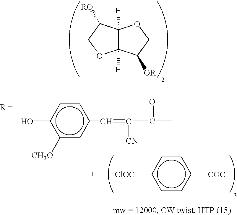
(Non-photoreactive Chiral Compound) - In the invention, it is preferable to include a non-photoreactive chiral compound, together with the above-described photoreactive chiral compounds, to make the liquid crystal composition display selective reflection of a desired color. From the viewpoints of improving color hues and color purity of the liquid crystal compound, preferable examples of the non-photoreactive chiral compound include isomannide, catechin, isosorbide, fenchone and carvone. Additional examples include chiral compounds described, for example, in Japanese Patent Application Laid-Open (JP-A) No. 2000-44451, Japanese National Publication No. 10-509726, WO 98/00428, Japanese National Publication Nos. 2000-506873 and 9-506088, Liquid Crystals 1996, 21, 327 and
Liquid Crystals 1998, 24, 219. - The content of the chiral compound is preferably 5 to 30% by mass relative to the total solid content of the liquid crystal composition.
- (Polymerization Initiator)
- If a polymerization reaction is utilized for the liquid crystal compound having a polymerizable group to fix the helical structure after the twisting power has been changed by irradiating the liquid crystal with light, a polymerization initiator is added to the composition. The polymerization initiator can suitably be selected from conventionally known compounds that are photoreactive and thermoreactive. Among others, photo-polymerization initiators capable of accelerating a reaction by light irradiation are particularly preferable. In order to fix the helical structure after the desired helical structure has been formed, the polymerization reaction of the liquid crystal composition is preferably allowed to proceed rapidly.
- Examples of the photo-polymerization initiator suitably selected from conventionally known initiators include p-methoxyphenyl-2,4-bis(trichloromethyl)-s-triazine, 2-(p-butoxystyryl)-5-trichloromethyl-1,3,4-oxadiazole, 9-phenylacridine, 9,10-dimethylbenzphenazine, benzophenon/Michler's ketone, hexaarylbiimidazole/mercaptobenzimidazole, benzyldimethylketal, thioxanthone/amine, triarylsulfonium hexafluorophosphate, bisacylphosphine oxides such as bis-(2,4,6-trimethylbenzoyl)phenylphosphine oxide described in JP-A No. 10-29997 and acylphosphine oxides such as those described in DE4230555 by Lucirin TPO.
- The polymerization initiators having a different spectrally sensitive range from that of the photoreactive chiral compounds (described later) are preferably chosen. Here, having a different spectrally sensitive range refers to that their central photosensitive wavelengths do not overlap each other, and alignment of the liquid crystal is not altered at the time of imagewise exposure and polymerization for hardening, to an extent that image displaying property and color purity may not be impaired. In order to avoid overlapping of the central photosensitive wavelengths, a band pass filter or the like is used to control the wavelength of light irradiated, in addition to suitably selecting the molecular structures of the both compounds.
- The content of the polymerization initiator is preferably 0.1 to 20% by mass, and more preferably 0.5 to 5% by mass relative to the total solid content of the liquid crystal composition. If the content is less than 0.1% by mass, curability at the time of irradiating light may be lowered, occasionally requiring a prolonged time for hardening. If the content exceeds 20% by mass, light transmittance in the ultraviolet-visible region may be decreased.
- (Polymerizable Monomer)
- The liquid crystal composition of the invention may further include a polymerizable monomer. If the polymerizable monomer is included in the liquid crystal composition, the monomer serves to fix the helical structure (to display selective reflection) of the liquid crystal after the twisting power of the liquid crystal has been changed by light irradiation and a distribution of selectively reflected wavelengths has been established (patterning), whereby the strength of the fixed liquid crystal composition can be further increased. However, the polymerizable monomer needs not always be included if the nematic liquid crystal compound has an unsaturated bond within a molecule.
- As the polymerizable monomer, a monomer having an ethylenically unsaturated bond may be exemplified. Specific examples thereof include polyfunctional monomers such as pentaerythritol tetracrylate and dipentaerythritol hexacrylate.
- Specific examples of the monomer having an ethylenically unsaturated bond are shown below. However, these examples are not limiting the present invention.

- The content of the polymerizable monomer is preferably 0.5 to 50% by mass relative to the total solid content of the liquid crystal composition. If the content is less than 0.5% by mass, sufficient curability may not be obtained. If the content exceeds 50% by mass, the polymerizable monomer may interfere alignment of the liquid crystal molecules, occasionally leading to insufficient color development.
- (Air Interface Alignment Agent)
- In the invention, it is preferable to include in the liquid crystal composition a surfactant which exerts an excluded volume effect distributed over an air interface side (hereinafter referred to as an “air interface alignment agent”). If an air interface alignment agent is included, the agent serves to three-dimensionally control an alignment state at a surface of the layer interfacing with air, when a liquid crystal composition is applied in a state of a coating solution. Particularly when the agent is applied in a cholesteric liquid crystal phase, light of selectively reflected wavelength having higher color purity can be obtained.
- An air interface alignment agent is a surfactant exerting an excluded volume effect. As used herein, exerting an excluded volume effect means control of aligning liquid crystal (molecules) at the air interface side, that is, three-dimensional control of a spatial alignment state of a liquid crystal at a layer surface interfacing with air when a layer including a liquid crystal composition is formed by application of coating. In more detail, this term means control of pre-tilt angles of liquid crystal molecules at the air interface side.
- The requirements for a preferable molecular structure of an air interface alignment agent are to have a flexible hydrophobic moiety and a moiety having at least one ring unit and a structural stiffness (hereinafter referred to as a stiff moiety). The flexible hydrophobic moiety can be either a perfluoro chain or a long alkyl chain depending on the kind of a liquid crystal compound used. Since a hydrophobic moiety is flexible, the hydrophobic moiety can effectively be located on the air side.
- An air interface alignment agent may be of a short molecular chain having a molecular weight of the order of several hundreds or of the polymer or the oligomer consisting of the short molecular chain. Furthermore, there may be included a polymerizable functional group in the molecule of the agent depending on the use purposes.
- When such an air interface alignment agent is used, a flexible hydrophobic moiety of an air interface alignment agent is arranged to the air interface; and at the same time, a stiff moiety is arranged to a liquid crystal molecule orientation, shaped to be flat and positioned in parallel to the air interface, to thereby permit alignment of liquid crystal molecules parallel to the air interface.
- On the other hand, if a stiff moiety is oriented in a direction perpendicular to the air interface, liquid crystal molecules can be aligned in a direction perpendicular to the air interface.
- Specifically, a nonionic surfactant is preferably used and the following compounds may be exemplified.


- The addition amount of an air interface alignment agent is preferably a quantity to cover a surface of the air interface side of a layer including a liquid crystal composition by one molecule, and preferably of from 0.05 to 5 mass % and more preferably of from 0.1 to 1.0 mass % relative to the total solid content of the liquid crystal composition. When the addition amount is less than 0.05 mass %, the effects of the agent are not always exerted, while when the addition amount is in excess of 5 mass %, an air interface alignment agent itself occasionally causes an association, resulting in phase separation from liquid crystal.
- If an air interface alignment agent is used, a surface tension can be decreased. Other kinds of surfactants than the air interface alignment agent can be used together with this agent for the purpose of further reducing a surface tension and improving coatability.
- (Additional Components)
- As additional components, the following may be included in the composition: a binder resin, a solvent, a surfactant, a polymerization inhibitor, a thickening agent, a dye, a pigment, an ultraviolet absorbent, a gelling agent and so on.
- Examples of the binder resin include polystyrene compounds such as polystyrene and poly-α-methylstyrene; cellulose resins such as methylcellulose, ethylcellulose and acetylcellulose; acidic cellulose derivatives having, as its side chain, a carboxylic group; acetal resins such as polyvinyl formal and polyvinyl butyral; and methacrylic acid copolymer, acrylic acid copolymer, itaconic acid copolymer, crotonic acid copolymer, maleic acid copolymer and partially-esterified maleic acid copolymer described in JP-A Nos. 59-44615, Japanese Patent Application Publication (JP-B) Nos. 54-34327, 58-12577 and 54-25957, JP-A Nos. 59-53836 and 59-71048.
- As other examples of the binder resin, there may be exemplified a homopolymer of an acrylic acid alkyl ester and a homopolymer of methacrylic acid alkyl ester in which an alkyl group may preferably be a methyl, ethyl, n-propyl, n-butyl, iso-butyl, n-hexyl, cyclohexyl, 2-ethylhexyl or the like group.
- Besides, the binder resin may be a polymer having a hydroxyl group to which is added an acid anhydride, benzyl(meth)acrylate/(methacrylic acid homopolymer)acrylic acid copolymer, a multiple copolymer of benzyl(meth)acrylate/(meth)acrylic acid/another monomer, or the like.
- The addition amount of the binder resin in the liquid crystal composition is preferably from 0 to 50% by mass, and more preferably from 0 to 30% by mass. If the amount is more than 50% by mass, alignment of the cholesteric liquid crystal compound may sometimes become insufficient.
- In the liquid crystal composition of the invention, it is particularly preferable to use a surfactant, in combination with the photoreactive chiral agent and the liquid crystal compound, preferably a nematic liquid crystal compound. As the surfactant, a surfactant exerting an excluded volume effect is preferably used. Here, “exerting an excluded volume effect” means that the surfactant serves to three-dimensionally control a spatial alignment state at the surface of the layer interfacing with air. Specifically, a nonionic surfactant is preferable and suitably selected for use from the conventionally known nonionic surfactants.
- The polymerization inhibitor may be added to the composition to improve storability. Examples of the polymerization inhibitor include hydroquinone, hydroquinone monomethyl ether, phenothiazine, benzoquinone, and the derivatives thereof. The addition amount of the polymerization inhibitor is preferably from 0 to 10% by mass, more preferably from 0 to 5% by mass, relative to the content of the polymerizable monomer.
- The liquid crystal composition may be prepared by dissolving or dispersing the aforementioned respective components in a suitable solvent and formed into an arbitrary shape, or disposed onto a support or the like for use. Examples of the solvent include 2-butanone, cyclohexanone, methylene chloride and chloroform.
- Next, the liquid crystal composition according to the second aspect of the invention is described. The liquid crystal composition according to the second aspect is the same as that according to the first aspect, except that the composition comprises a single kind of photoreactive chiral compound.
- The photoreactive chiral compound in the composition according to the second aspect is a compound that undergoes reversible isomerization when irradiated with either of two light beams having mutually different wavelengths and exhibits an HTP after isomerization by each light beam, which HTPs are mutually different. For example, the photoreactive chiral compound shown below isomerizes to a compound having an HTP of 136 when irradiated with light having a wavelength of 366 nm, which latter compound reversibly isomerizes to the former compound having an HTP of 28 when irradiated with light of 495 nm.

- The followings are specific examples of the photoreactive chiral compound used in the second aspect, however, these examples are not intended to limit the invention.


Change in Helical Structure of Liquid Crystal - As described above, the liquid crystal composition of the invention comprises the photoreactive chiral compound, and when the composition is patternwise irradiated with light beams each having different wavelengths, the twisting power of the liquid crystal is altered to form the regions in which respective helical structures have different twisting degrees (twisting power; HTP).
- Particularly in case where the liquid crystal phase is a cholesteric liquid crystal phase, selective color reflection can arbitrarily be obtained by changing the twisting power of the liquid crystal. If a changing ratio of the twisting power (changing ratio of a twist) is large, a range of selective color reflection displayed by the liquid crystal is wide, whereby a broad range of selectively reflected wavelengths including three primary colors (B, G, R) can be obtained.
- Specifically, selective color reflection can be achieved in the following manner.
- When the liquid crystal composition of the invention is irradiated with light having wavelengths to which the photoreactive chiral compound included therein is photosensitive, the compound responds to the wavelength of the irradiated light and isomerizes to induce a change in the helical structure (twist angle) of the liquid crystal, and this structural change allows selective reflection of different colors to thereby form an imagewise pattern (patterning). Thus, by irradiating light beams of varied wavelengths for respective desired regions, a plurality of colors can be reflected depending on the used wavelengths. And by irradiating light through an imagewise formed photomask having different transmissive areas, colored regions selectively reflecting different colors can be formed.
- When a liquid crystal color filter, an optical film (described later) or the like is produced, patterning exposure is conducted as described above by imagewise irradiating light having wavelengths to which the photoreactive chiral compound is photosensitive, followed by additional irradiation to cause photo-polymerization of the polymerizable groups for curing the liquid crystal composition to thereby fix the helical structure of the liquid crystal, such that selective reflection of desired colors can be displayed. This process will be described in detail later.
- As the light source for use in the irradiation, the light sources which emit UV light are preferably used from the viewpoints of having high energy and of causing rapid structure change and a swift polymerization reaction of the liquid crystal compound. Preferable examples of the light source include a high-pressure mercury lamp, a metal halide lamp and an Hg—Xe lamp. The light source preferably has a function of varying light quantities.
- Fixing of Helical Structure of Liquid Crystal
- As described above, by irradiating the photoreactive chiral compound with light having specified wavelengths, the twisting power of the co-existing liquid crystal may be altered to cause a change in the helical structure. The liquid crystal composition of the invention comprises a liquid crystal compound having polymerizable groups, a photo-polymerization initiator and at least one photoreactive chiral compound. By effecting polymerization or cross-linking of the liquid crystal compound, the altered helical structure can be fixed, and further strength of the fixed liquid crystal composition can be enhanced.
- It is preferable to use the photo-polymerization initiator and the photoreactive chiral compound whose spectral sensitive range is different with each other.
- Specifically, selective color reflection can be achieved in the following manner.
- First, similarly to the patterning exposure described in the section of “Change in Helical Structure of Liquid Crystal” above, the liquid crystal composition of the invention is irradiated with light having wavelengths to which the photoreactive compound included therein is photosensitive. By this irradiation, the co-existing photoreactive compound responds to the wavelength of irradiated light and isomerizes to induce a change in the helical structure, leading to formation of an imagewise pattern (patterning). After this patterning, another irradiation is conducted using another light beam having wavelengths to which the photo-polymerization initiator is photosensitive. By this irradiation, the photo-polymerization initiator responds to the wavelength and causes polymerization of the liquid crystal compound, thereby fixing the composition and maintaining the altered helical structure. Prior to this step, an additional step of, e.g., nitrogen replacement, may be performed.
- In case where the spectrally sensitive range of the photoreactive chiral agent does not overlap with that of the photo-polymerization initiator, irradiation for changing the HTP and irradiation for photo-polymerization do not affect each other. Thus, when imagewise exposure is conducted to induce a change in HTPs, photo-polymerization of the liquid crystal composition does not progress, whereby patterning can be achieved with an intended HTP changing ratio. Further, when the photo-polymerization is conducted to fix the helical structure, the photoreactive compound does not respond to light irradiation, whereby the changed HTP pattern thus formed can securely be fixed.
- When a liquid crystal color filter, an optical film (described later) or the like is produced, patterning exposure is conducted as described above by imagewise irradiating light having wavelengths to which the photoreactive compound is photosensitive, followed by additional irradiation to cause photo-polymerization of the polymerizable group for curing the liquid crystal composition to thereby fix the helical structure of the liquid crystal, such that selective reflection of desired colors can be displayed. This process will be described in detail later.
- The light source for use in the irradiation is the same as those exemplified in the section of “Change in Helical Structure of Liquid Crystal” above.
- Although the above-described process utilizes polymerization for fixing the liquid crystal composition, fixing may be effected by, for example, cross-linking through vulcanization or causing glass phase transition.
- Selectively Reflective Film
- A selectively reflective film of the invention comprises the above-described liquid crystal composition of the invention. The selectively reflective film can be produced by patternwise irradiating the liquid crystal composition with light having suitable wavelengths for achieving purposes described in the section “Change in Helical Structure of Liquid Crystal” or “Fixing of Helical Structure of Liquid Crystal” above.
- Through explaining a production process, the selectively reflective film of the invention is described hereinafter in detail.
- The selectively reflective film of the invention is produced from the liquid crystal composition of the invention.
- In the method for producing the selectively reflective film, the liquid crystal composition is prepared such that the composition displays selective reflection of a first color, then the liquid crystal composition is coated on a substrate, and thereafter the liquid crystal composition is imagewise irradiated with light having a first wavelength to display selective reflection of a second color. Then, the liquid crystal composition is imagewise irradiated with light having a second wavelength, which is different from the first wavelength, to display selective reflection of a third color. Thereafter, the liquid crystal composition is further irradiated with light having a range of wavelengths to which the polymerization initiator is spectrally sensitive to cause photo-polymerization and hardening (hereinafter, this step may be referred to as an “irradiating step”). Further, depending on a suitably selected embodiment for producing a selectively reflective film, the method may further comprise steps of aligning the liquid crystal composition at a surface thereof (aligning step), transferring a liquid crystal layer by adhering and removing a transfer material (transferring step), coating a nematic liquid crystal composition to form a liquid crystal layer (coating step) and the like.
- The following is a specific embodiment illustrating a production process, which comprises the irradiating step described above.
- Irradiating Step
- In the irradiating step, light irradiation is conducted for both patterning and fixing (polymerization and hardening) the liquid crystal compound. That is, light beams having the first and the second wavelengths to which the photoreactive chiral compound is highly photosensitive are imagewise irradiated for patterning, followed by irradiating another light having wavelengths to which the polymerization initiator is highly photosensitive to cause polymerization for fixing the helical structure of the liquid crystal compound, such that desired selective color reflection is displayed.
- When the liquid crystal composition is irradiated with light having a first wavelength, the photoreactive chiral compound included therein responds to the wavelength and causes a change in the helical structure of the liquid crystal, and this structural change allows selective reflection of different colors, to thereby form an imagewise pattern. Thus, by irradiating light beams of varied wavelengths for respective desired regions, a plurality of colors can be obtained corresponding to the used wavelengths. For example, by irradiating light through an imagewise formed photomask having different transmissive areas, colored regions selectively reflecting different colors can be formed. Then, by further irradiating light having wavelengths to which the polymerization initiator is photosensitive to effect curing (fixing), a liquid crystal color filter can be produced.
- The illuminance (illumination intensity) of the light for patterning and polymerization (curing) is not particularly limited and may be suitably selected depending on the used materials so as to obtain sufficient photosensitivity for patterning and polymerization (curing). As the light source for irradiating the first and the second light, light sources similar to those used for irradiating the liquid crystal composition described above can be used.
- More specifically, the selectively reflective color filter may preferably be produced according to a first or a second embodiment described below.
- (1) The Step of Providing the Liquid Crystal Composition in the Form of a Coating Solution on a Tentative Support to Prepare a Transfer Material Containing at Least a Liquid Crystal Layer
- The liquid crystal composition in the form of a coating solution can be prepared by dissolving or dispersing each component in an appropriate solvent. Examples of the solvent include 2-butanone, cyclohexanone, methylene chloride and chloroform.
- If foreign matters or the like are present on a material to be transferred, a cushioning layer containing a thermoplastic resin or the like may be disposed between the liquid crystal layer and the tentative support in order to secure adhesiveness at the time of transferring the material. It is also preferable to subject the surface of the cushioning layer to aligning treatment such as rubbing (aligning step).
- (2) The Step of Laminating the Transfer Material on a Light Transmissive Substrate
- In addition to the light transmissive substrate, there may be used an image receiving material comprising a substrate and having disposed thereon an image receiving layer. Alternatively, the liquid crystal composition may directly be provided on the substrate by applying coating (a coating step), without using the transfer material. Applying coating may be conducted by employing suitably selected known methods using a bar coater, a spin coater, and the like. In consideration of material loss and cost, the transferring method is preferable.
- (3) The Step of Removing the Transfer Material From the Light Transmissive Substrate to Provide a Cholesteric Liquid Crystal Layer on the Substrate (a Transferring Step)
- The liquid crystal layer may have a multi-layer construction by further laminating additional layers after the step (4) described below.
- (4) The step of imagewise irradiating the cholesteric liquid crystal layer with UV light having the first wavelength through a photomask to form a pixel pattern capable of selective color reflection, and thereafter irradiating UV light having the second wavelength through another photomask having a different pattern from that of the previous photomask to form another pixel pattern which is different from that formed by light having the first wavelength, and further irradiating UV light to harden the liquid crystal layer (irradiating step).
- (1) The Step of Forming the Liquid Crystal Layer by Directly Providing the Liquid Crystal Composition on a Support for Producing a Color Filter
- The liquid crystal layer can be formed by applying coating of the liquid crystal composition, which is prepared in the form of a coating solution similarly to the above-described embodiment, through conventionally known methods using a bar coater, spin coater or the like.
- Further, an alignment layer may be disposed, similarly to the first embodiment described above, between the cholesteric liquid crystal layer and the tentative support. The alignment layer may be subjected to aligning treatment such as rubbing at a surface thereof (aligning step).
- (2) Irradiating Step Similar to the Step (4) in the First Embodiment
- The thickness of the liquid crystal layer (liquid crystal composition in the form of a sheet), which serves as a liquid crystal color filter, is preferably 1.5 to 4 g m.
- The invention is further described referring to the drawings.
FIGS. 1A to 1I schematically represent an embodiment of the process for producing a liquid crystal color filter of the invention. - First, each of the above-described components is dissolved in a suitable solvent to prepare a cholesteric liquid crystal composition in the form of a coating solution. The components and the solvent are the same as described above.
- As shown in
FIG. 1A , a support 10 (hereinafter also referred to as a “tentative support”) is prepared. On thesupport 10, a cushioning layer (thermoplastic resin layer) 12 is provided by applying coating of, for example, an acrylic resin, polyester or polyurethane. Further, analignment layer 14 comprising polyvinyl alcohol or the like is laminated thereon. The alignment layer is subjected to rubbing treatment as shownFIG. 1B . Although the rubbing treatment is not always necessary, this treatment can improve aligning property. - Next, as shown in
FIG. 1C , the cholesteric liquid crystal composition in the form of a coating solution is provided on thealignment layer 14 and then dried to form a cholestericliquid crystal layer 16. Thereafter, acover film 18 is provided on theliquid crystal layer 16 to prepare a transfer material. The transfer material is hereinafter referred to as atransfer sheet 20. Here, the cholesteric liquid crystal composition is prepared to include two kinds of photoreactive chiral compounds that are photosensitive to light beams having mutually different wavelengths and capable of reflecting light of the green color (G) while transmitting light of the blue color (B) and light of the red color (R). - Then, as shown in
FIG. 1D , anothersupport 22 is prepared. On thesupport 22, analignment layer 24 is formed in the same manner as described above, and rubbing treatment is performed at a surface of thealignment layer 24. The resultant support is hereinafter referred to as acolor filter substrate 26. - Subsequently, the
cover film 18 is peeled off from thetransfer sheet 20. Then thetransfer sheet 20 is superposed on thecolor filter substrate 26 so that the surface of the cholestericliquid crystal layer 16 of thetransfer sheet 20 is brought into contact with the surface of thealignment layer 24 of thecolor filter substrate 26 as shown inFIG. 1E , followed by lamination through a roll rotating in a direction of the arrow in the drawing. Thereafter, as shown inFIG. 1F , the tentative support and the cushioning layer are removed from thealignment layer 14 of thetransfer sheet 20. Thus, the cholestericliquid crystal layer 14 is transferred, together with the alignment layer, onto the color filter substrate. In this case, thecushioning layer 12 may not necessarily be removed together with thetentative support 10. - After the transfer, as shown in
FIG. 1G , aphotomask 28 is arranged on thealignment layer 14 and the cholestericliquid crystal layer 16 is patternwise irradiated with light having the first wavelength through thephotomask 28. Then, another photomask (not shown) having a pattern different from that of thephotomask 28 is arranged and another patternwise irradiation is conducted using light having the second wavelength. The cholestericliquid crystal layer 16 comprises a photoreactive chiral compound to undergo isomerization when irradiated with light having the first wavelength and another photoreactive chiral compound to undergo isomerization when irradiated with light having the second wavelength. Thus, there are formed regions, corresponding to the pattern of the photomask, consisting of a region reflecting green light (G) while transmitting blue light (B) and red light (R), a region reflecting blue light (B) while transmitting green light (G) and red light (R), and a region reflecting red light (R) while transmitting green light (G) and blue light (B). - Then, as shown in
FIG. 1H , the formed pattern is fixed by further irradiating the cholestericliquid crystal layer 16 with UV light at an illumination intensity which is different from that used in the above step 1G. Thereafter, unnecessary portions (for example, residual portions such as the cushioning layer and the intermediate layer, and unexposed portions) on the cholestericliquid crystal layer 16 are removed using 2-butanone, chloroform or the like solvent, to finally form a cholesteric liquid crystal layer having respective regions to display each of the BGR light reflection, as shown inFIG. 11 . - While the schematic diagrams shown in
FIGS. 1A to 1I represent one typical process for producing a color filter according to a laminating method, another production process according to an applying method may be used in which a liquid crystal layer is directly provided by applying coating on a color filter substrate to form a color filter. In the latter case, a cholesteric liquid crystal layer is formed by applying coating on thealignment layer 24 of thecolor filter substrate 26 shown inFIG. 1D and dried, after which the steps shown inFIGS. 1G to 1I are successively performed. - The steps, and the materials for the transfer material, the support and the like are detailed in Japanese Patent Application Nos. 11-342896 and 11-343665, which have previously been filed by the present inventors.
- 1. Preparation of Substrate
- A coating solution for a polyimide alignment layer (LX-1400 manufactured by Hitachi Chemistry Dupont Co., Ltd.) was applied on a glass substrate using a spin coater, followed by drying in an oven at 100° C. for 5 minutes and subsequent heating in the oven at 250° C. for 1 hour for baking, to thereby form an alignment layer. Then an aligning treatment was conducted at the surface of this layer by rubbing to prepare the glass substrate having formed thereon an alignment layer.
- 2. Formation of Photosensitive Layer
- A coating solution for a photosensitive liquid crystal layer prepared according to the following formulation was applied using a spin coater on the alignment layer disposed on the glass substrate produced as above, followed by drying in the oven at 100° C. for 2 minutes to form a photosensitive liquid crystal layer. The thickness of the layer was measured using a confocal microscope and found to be 2.3 μm.
[Formulation of the coating solution for the photosensitive liquid crystal layer (1)] 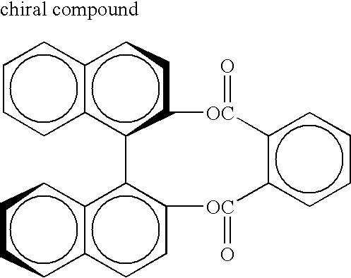
1.1 parts by mass 
1.8 parts by mass 
1.8 parts by mass 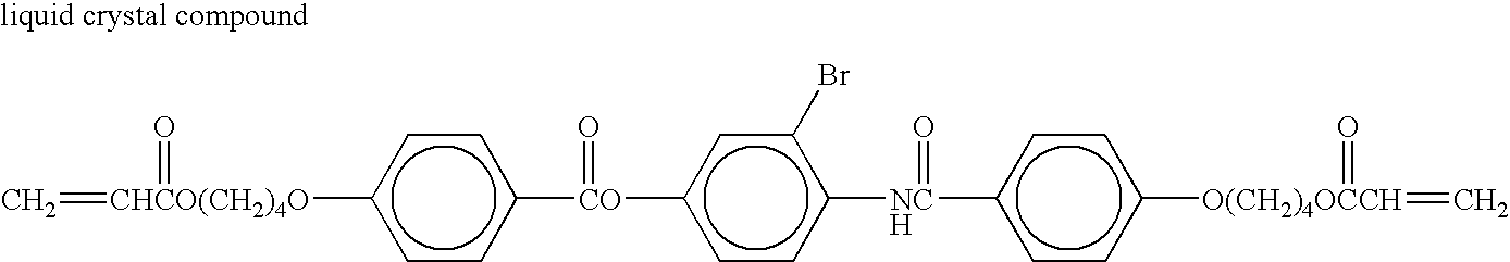
92.4 parts by mass 
0.2 parts by mass 
2 parts by mass polymerization inhibitor Hydroquinone monomethyl ether 0.5 part by mass solvent Cyclohexanone 350 parts by mass
3. Patterning of Color Filter - a) Patterning of R color: the photosensitive liquid crystal layer was irradiated with light through a photomask having 80 μm-wide openings and an interference filter having a central wavelength of transmission at 405 nm, at the positions corresponding to R color, using a super-high pressure mercury lamp at illumination intensity of 20 mW/cm2 at room temperature for 10 seconds.
- b) Patterning of B color: the photosensitive liquid crystal layer was irradiated with light through a photomask having 80 μm-wide openings and an interference filter having a central wavelength of transmission at 313 nm, at the positions corresponding to B color, using a super-high pressure mercury lamp at illumination intensity of 10 mW/cm2 at room temperature for 10 seconds.
- 4. Fixing of Color Filter by Polymerization
- Then, the resultant glass substrate was maintained on a hot plate at a temperature of 110° C. for 1 minute to align the photosensitive liquid crystal layer. Subsequently, under nitrogen atmosphere and at 60° C., light was irradiated using a super-high pressure mercury lamp at illumination intensity of 100 mW/cm2 through an interference filter having a central wavelength of transmission at 313 nm for 5 seconds to thereby polymerize and harden the photosensitive liquid crystal layer. Then, heat application was further conducted at 250° C. for 15 minutes to accelerate hardening of the resultant layer.
- The thus produced color filter was measured for a central wavelength of transmission at each region displaying selective reflection of one of the colors B, G or R, which central wavelengths were respectively 450 nm, 540 nm and 650 nm. A variation in central selective reflection at each of the color regions was within ±1.5 nm and thus revealed to be highly uniform.
- 1. Preparation of Substrate
- A glass substrate provided with an alignment layer was prepared in the same manner as in Example 1.
- 2. Formation of Photosensitive Layer
- A coating solution for a photosensitive liquid crystal layer prepared according to the following formulation was applied on the alignment layer of the glass substrate, formed as above, using a spin coater followed by drying in an oven at 100° C. for 2 minutes, to form a photosensitive liquid crystal layer. The thickness of the layer measured using a confocal microscope was 2.4 μm.
[Formulation of the coating solution for the photosensitive liquid crystal layer (2)] 
7.8 parts by mass 
3.0 parts by mass 
2.1 parts by mass 
84.4 parts by mass 
0.2 part by mass 
2 parts by mass polymerization inhibitor Hydroquinone monomethyl ether 0.5 part by mass solvent Cyclohexanone 350 parts by mass
3. Patterning of Color Filter - a) Patterning of R color: the photosensitive liquid crystal layer was irradiated with light through a photomask having 80 μm-wide openings and an interference filter having a central wavelength of transmission at 365 nm, at the positions corresponding to R color, using a super-high pressure mercury lamp at illumination intensity of 20 mW/cm2 at room temperature for 10 seconds.
- b) Patterning of B color: the photosensitive liquid crystal layer was irradiated with light through a photomask having 80 μm-wide openings and an interference filter having a central wavelength of transmission at 313 nm, at the positions corresponding to B color, using a super-high pressure mercury lamp at illumination intensity of 10 mW/cm2 at room temperature for 10 seconds.
- 4. Fixing of Color Filter by Polymerization
- Then, the resultant glass substrate was maintained on a hot plate at a temperature of 110° C. for 1 minute to align the photosensitive liquid crystal layer. Subsequently, under nitrogen atmosphere and at 60° C., light was irradiated using a super-high pressure mercury lamp at illumination intensity of 100 mW/cm2 through an interference filter having a central wavelength of transmission at 313 nm for 5 seconds to thereby polymerize and harden the photosensitive liquid crystal layer. Then, heat application was further conducted at 250° C. for 15 minutes to promote hardening of the resultant layer.
- The thus produced color filter was measured for a central wavelength of transmission at each region displaying selective reflection of one of the colors B, G or R, which central wavelengths were respectively-455 nm, 535 nm and 650 nm. A variation in central selective reflection at each of the color regions was within ±1.5 nm and thus revealed to be highly uniform.
- 1. Preparation of Substrate
- A glass substrate provided with an alignment layer was prepared in the same manner as in Example 1.
- 2. Formation of Photosensitive Layer
- A coating solution for a photosensitive liquid crystal layer prepared according to the following formulation was applied on the alignment layer of the glass substrate, formed as above, using a spin coater followed by drying in an oven at 100° C. for 2 minutes, to form a photosensitive liquid crystal layer. The thickness of the layer measured using a confocal microscope was 2.4 μm.
[Formulation of the coating solution for the photosensitive liquid crystal layer (3)] 
4.5 parts by mass 
1.7 parts by mass 
2.6 parts by mass 
88.5 parts by mass 
0.2 part by mass 
2 parts by mass polymerization inhibitor Hydroquinone monomethyl ether 0.5 part by mass solvent Cyclohexanone 350 parts by mass
3. Patterning of Color Filter - a) Patterning of R color: the photosensitive liquid crystal layer was irradiated with light through a photomask having 80 μm-wide openings and an interference filter having a central wavelength of transmission at 365 nm, at the positions corresponding to G color and R color, using a super-high pressure mercury lamp at illumination intensity of 20 mW/cm2 at room temperature for 15 seconds.
- b) Patterning of R color: the photosensitive liquid crystal layer was irradiated with light through a photomask having 80 μm-wide openings and an interference filter having a central wavelength of transmission at 313 nm, at the positions corresponding to R color, using a super-high pressure mercury lamp at illumination intensity of 10 mW/cm2 at room temperature for 10 seconds.
- 4. Fixing of Color Filter by Polymerization
- Then, the resultant glass substrate was maintained on a hot plate at a temperature of 110° C. for 1 minute to align the photosensitive liquid crystal layer. Subsequently, under nitrogen atmosphere and at 60° C., light was irradiated using a super-high pressure mercury lamp at illumination intensity of 100 mW/cm2 through an interference filter having a central wavelength of transmission at 313 nm for 5 seconds to thereby polymerize and harden the photosensitive liquid crystal layer. Then, heat application was further conducted at 250° C. for 15 minutes to facilitate hardening of the resultant layer.
- The thus produced color filter was measured for a central wavelength of transmission at each region displaying selective reflection of one of the colors B, G or R, which central wavelengths were respectively 453 nm, 535 nm and 655 nm. A variation in central selective reflection at each of the color regions was within +1.5 nm and thus revealed to be highly uniform.
- 1. Preparation of Substrate
- A glass substrate provided with an alignment layer was prepared in the same manner as in Example 1.
- 2. Formation of Photosensitive Layer
- A coating solution for a photosensitive liquid crystal layer prepared according to the following formulation was applied on the alignment layer of the glass substrate, formed as above, using a spin coater followed by drying in an oven at 100° C. for 2 minutes, to form a photosensitive liquid crystal layer. The thickness of the layer measured using a confocal microscope was 2.3 μm.
[Formulation of the coating solution for the photosensitive liquid crystal layer (4)] 
4.4 parts by mass 
3.9 parts by mass 
2.1 parts by mass 
89.6 parts by mass 
0.2 part by mass 
2 parts by mass polymerization inhibitor Hydroquinone monomethyl ether 0.5 part by mass solvent Cyclohexanone 350 parts by mass
3. Patterning of Color Filter - a) Patterning of G color: the photosensitive liquid crystal layer was irradiated with light through a photomask having 80 μm-wide openings and an interference filter having a central wavelength of transmission at 365 nm, at the positions corresponding to G color, using a super-high pressure mercury lamp at illumination intensity of 20 mW/cm2 at room temperature for 15 seconds.
- b) Patterning of B color: the photosensitive liquid crystal layer was irradiated with light through a photomask having 80 μm-wide openings and an interference filter having a central wavelength of transmission at 313 nm, at the positions corresponding to B color, using a super-high pressure mercury lamp at illumination intensity of 8 mW/cm2 at room temperature for 20 seconds.
- 4. Fixing of Color Filter by Polymerization
- Then, the resultant glass substrate was maintained on a hot plate at a temperature of 110° C. for 1 minute to align the photosensitive liquid crystal layer. Subsequently, under nitrogen atmosphere and at 60° C., light was irradiated using a super-high pressure mercury lamp at illumination intensity of 100 mW/cm2 through an interference filter having a central wavelength of transmission at 313 nm for 5 seconds to thereby polymerize and harden the photosensitive liquid crystal layer. Then, heat application was further conducted at 250° C. for 15 minutes to facilitate hardening of the resulting layer.
- The thus produced color filter was measured for a central wavelength of transmission at each region displaying selective reflection of one of the colors B, G or R, which central wavelengths were respectively 448 nm, 543 nm and 650 nm. A variation in central selective reflection at each of the color regions was within ±1.5 nm and thus revealed to be highly uniform.
Claims (20)
1. A liquid crystal composition comprising:
a liquid crystal compound containing at least one polymerizable group;
two or more kinds of photoreactive chiral compounds that undergo isomerization when respectively irradiated with light beams having mutually different wavelengths and exhibit mutually different HTPs after isomerization; and
a polymerization initiator.
2. A liquid crystal composition comprising:
a liquid crystal compound containing at least one polymerizable group;
a photoreactive chiral compound that undergoes reversible isomerization when irradiated with either of two light beams having mutually different wavelengths and exhibits an HTP after isomerization by each light beam, which HTPs are mutually different; and
a polymerization initiator.
3. The liquid crystal composition according to claim 1 , further comprising a non-photoreactive chiral compound.
4. The liquid crystal composition according to claim 2 , further comprising a non-photoreactive chiral compound.
5. (canceled)
6. (canceled)
7. (canceled)
8. A selectively reflective film produced by polymerizing and curing a liquid crystal composition comprising a liquid crystal compound containing at least one polymerizable group; two or more kinds of photoreactive chiral compounds that undergo isomerization when respectively irradiated with light beams having mutually different wavelengths and exhibit mutually different HTPs after isomerization; and a polymerization initiator.
9. The selectively reflective film according to claim 8 , wherein the liquid crystal composition further comprises a non-photoreactive chiral compound.
10. (canceled)
11. A selectively reflective film produced by polymerizing and curing a liquid crystal composition comprising a liquid crystal compound containing at least one polymerizable group; a photoreactive chiral compound that undergoes reversible isomerization when irradiated with either of two light beams having mutually different wavelengths and exhibits an HTP after isomerization by each light beam, which HTPs are mutually different; and a polymerization initiator.
12. The selectively reflective film according to claim 11 , wherein the liquid crystal composition further comprises a non-photoreactive chiral compound.
13. (canceled)
14. A method for producing a selectively reflective film using a liquid crystal composition comprising a liquid crystal compound containing at least one polymerizable group; two or more kinds of photoreactive chiral compounds that undergo isomerization when respectively irradiated with light beams having mutually different wavelengths and exhibit mutually different HTPs after isomerization; and a polymerization initiator, the method comprising the steps of:
preparing the liquid crystal composition, which is capable of displaying selective reflection of a first color;
coating the liquid crystal composition on a surface of a substrate;
imagewise irradiating light having a first wavelength to which one of the photoreactive chiral compounds is photosensitive to undergo isomerization, such that selective reflection of a second color is displayed;
imagewise irradiating light having a second wavelength, which is different from the first wavelength and to which another of the photoreactive chiral compounds is photosensitive to undergo isomerization, such that selective reflection of a third color is displayed; and
polymerizing the liquid crystal compound.
15. The method for producing a selectively reflective film according to claim 14 , wherein the liquid crystal composition further comprises a non-photoreactive chiral compound.
16. (canceled)
17. A method for producing a selectively reflective film using a liquid crystal composition comprising a liquid crystal compound containing at least one polymerizable group; a photoreactive chiral compound that undergoes reversible isomerization when irradiated with either of two light beams having mutually different wavelengths and exhibits an HTP after isomerization by each light beam, which HTPs are mutually different; and a polymerization initiator, the method comprising the steps of:
preparing the liquid crystal composition, which is capable of displaying selective reflection of a first color;
coating the liquid crystal composition on a surface of a substrate;
imagewise irradiating light having a first wavelength to which the photoreactive chiral compound is photosensitive to undergo isomerization, such that selective reflection of a second color is displayed;
imagewise irradiating light having a second wavelength, which is different from the first wavelength and to which the photoreactive chiral compound is photosensitive to undergo isomerization, such that selective reflection of a third color is displayed; and
polymerizing the liquid crystal compound.
18. The method for producing a selectively reflective film according to claim 17 , wherein the liquid crystal composition further comprises a non-photoreactive chiral compound.
19. (canceled)
20. (canceled)
Priority Applications (1)
| Application Number | Priority Date | Filing Date | Title |
|---|---|---|---|
| US11/044,254 US20050127326A1 (en) | 2001-09-17 | 2005-01-28 | Liquid crystal composition, selectively reflective film and method for producing the same |
Applications Claiming Priority (4)
| Application Number | Priority Date | Filing Date | Title |
|---|---|---|---|
| JP2001-280981 | 2001-09-17 | ||
| JP2001280981A JP2003082352A (en) | 2001-09-17 | 2001-09-17 | Liquid crystal composition, selectively reflecting film, and its production process |
| US10/243,955 US6893585B2 (en) | 2001-09-17 | 2002-09-16 | Liquid crystal composition, selectively reflective film and method for producing the same |
| US11/044,254 US20050127326A1 (en) | 2001-09-17 | 2005-01-28 | Liquid crystal composition, selectively reflective film and method for producing the same |
Related Parent Applications (1)
| Application Number | Title | Priority Date | Filing Date |
|---|---|---|---|
| US10/243,955 Continuation US6893585B2 (en) | 2001-09-17 | 2002-09-16 | Liquid crystal composition, selectively reflective film and method for producing the same |
Publications (1)
| Publication Number | Publication Date |
|---|---|
| US20050127326A1 true US20050127326A1 (en) | 2005-06-16 |
Family
ID=19104888
Family Applications (2)
| Application Number | Title | Priority Date | Filing Date |
|---|---|---|---|
| US10/243,955 Expired - Fee Related US6893585B2 (en) | 2001-09-17 | 2002-09-16 | Liquid crystal composition, selectively reflective film and method for producing the same |
| US11/044,254 Abandoned US20050127326A1 (en) | 2001-09-17 | 2005-01-28 | Liquid crystal composition, selectively reflective film and method for producing the same |
Family Applications Before (1)
| Application Number | Title | Priority Date | Filing Date |
|---|---|---|---|
| US10/243,955 Expired - Fee Related US6893585B2 (en) | 2001-09-17 | 2002-09-16 | Liquid crystal composition, selectively reflective film and method for producing the same |
Country Status (2)
| Country | Link |
|---|---|
| US (2) | US6893585B2 (en) |
| JP (1) | JP2003082352A (en) |
Cited By (9)
| Publication number | Priority date | Publication date | Assignee | Title |
|---|---|---|---|---|
| GB2425774A (en) * | 2005-01-11 | 2006-11-08 | Merck Patent Gmbh | Polymerized liquid crystal film with low retardation |
| WO2007039104A1 (en) * | 2005-09-30 | 2007-04-12 | Merck Patent Gmbh | Chiral compounds |
| US20080278674A1 (en) * | 2007-05-08 | 2008-11-13 | Taiwan Tft Lcd Association | Method for fabricating reflective optical film and reflective polarizing film and method for fabricating the same |
| US20100149446A1 (en) * | 2007-03-30 | 2010-06-17 | Dic Corporation | Polymer-stabilized liquid crystal composition, liquid crystal display device, method for producing liquid crystal display device |
| US20130135566A1 (en) * | 2011-11-28 | 2013-05-30 | Wintek Corporation | Reflective liquid crystal display device and method of manufacturing the same |
| CN103176301A (en) * | 2011-12-21 | 2013-06-26 | 东莞万士达液晶显示器有限公司 | Reflective-type liquid crystal display device and manufacturing method thereof |
| CN103323964A (en) * | 2012-03-21 | 2013-09-25 | 东莞万士达液晶显示器有限公司 | Reflection type liquid crystal display device |
| US9229142B2 (en) | 2012-12-28 | 2016-01-05 | Fujifilm Corporation | Optical film, polarizing plate, liquid crystal display, and method of manufacturing optical film |
| US11332671B2 (en) | 2017-07-12 | 2022-05-17 | Fujifilm Corporation | Liquid crystal composition, method for producing reflective layer, reflective layer, cured product, and optically anisotropic body |
Families Citing this family (14)
| Publication number | Priority date | Publication date | Assignee | Title |
|---|---|---|---|---|
| JP2003082352A (en) * | 2001-09-17 | 2003-03-19 | Fuji Photo Film Co Ltd | Liquid crystal composition, selectively reflecting film, and its production process |
| JP4617641B2 (en) * | 2003-07-02 | 2011-01-26 | チッソ株式会社 | Liquid crystalline compounds and polymers having optically active groups |
| US7236151B2 (en) * | 2004-01-28 | 2007-06-26 | Kent Displays Incorporated | Liquid crystal display |
| US8199086B2 (en) | 2004-01-28 | 2012-06-12 | Kent Displays Incorporated | Stacked color photodisplay |
| US7470376B2 (en) * | 2004-10-29 | 2008-12-30 | Industrial Technology Research Institute | Photochemically active chiral compounds and compositions containing the same |
| US7452482B2 (en) * | 2004-12-15 | 2008-11-18 | Industrial Technology Research Institute | Photochemically active chiral compounds and compositions containing the same |
| JP4619250B2 (en) * | 2005-09-21 | 2011-01-26 | 富士フイルム株式会社 | Optical compensation sheet, polarizing plate, and liquid crystal display device |
| JP5242390B2 (en) * | 2006-06-27 | 2013-07-24 | 旭硝子株式会社 | Liquid crystal optical element and method for manufacturing liquid crystal optical element |
| JP2009180975A (en) * | 2008-01-31 | 2009-08-13 | Nitto Denko Corp | Optical laminate |
| JP5251857B2 (en) * | 2009-12-16 | 2013-07-31 | コニカミノルタアドバンストレイヤー株式会社 | Optical film |
| JP5304722B2 (en) * | 2010-05-07 | 2013-10-02 | コニカミノルタ株式会社 | Polarizing plate protective film and polarizing plate using the same |
| AP3541A (en) * | 2010-12-07 | 2016-01-13 | Sicpa Holding Sa | Composite marking based on chiral liquid crystal precursors |
| BR112013013792A2 (en) * | 2010-12-07 | 2016-09-13 | Sicpa Holding Sa | simplified control of color change properties of chiral crystalline liquid polymer |
| CN111902749B (en) | 2018-03-23 | 2022-09-20 | 富士胶片株式会社 | Method for producing cholesteric liquid crystal layer, liquid crystal composition, cured product, optically anisotropic body, and reflective layer |
Citations (14)
| Publication number | Priority date | Publication date | Assignee | Title |
|---|---|---|---|---|
| US5668614A (en) * | 1995-05-01 | 1997-09-16 | Kent State University | Pixelized liquid crystal display materials including chiral material adopted to change its chirality upon photo-irradiation |
| US5798057A (en) * | 1995-12-21 | 1998-08-25 | U.S. Philips Corporation | Method of manufacturing a switchable cholesteric filter as well as a luminaire having such a filter |
| US5827449A (en) * | 1996-05-14 | 1998-10-27 | Consortium Fur Elektrochemische Industrie Gmbh | Liquid-crystal mixtures, process for their preparation and their use |
| US5989461A (en) * | 1996-07-04 | 1999-11-23 | Merck Patent Gesellschaft Mit Beschrankter Haftung | Circular UV polarizer |
| US5995184A (en) * | 1998-09-28 | 1999-11-30 | Rockwell Science Center, Llc | Thin film compensators having planar alignment of polymerized liquid crystals at the air interface |
| US6099758A (en) * | 1997-09-17 | 2000-08-08 | Merck Patent Gesellschaft Mit Beschrankter Haftung | Broadband reflective polarizer |
| US6117920A (en) * | 1996-07-25 | 2000-09-12 | Merck Patent Gesellschaft Mit Beschrankter Haftung | Thermochromic polymerizable mesogenic composition |
| US6217955B1 (en) * | 1996-03-19 | 2001-04-17 | Merck Patent Gesellschaft Mit Beschrankter Haftung | Liquid crystal display device |
| US6466297B1 (en) * | 1999-07-02 | 2002-10-15 | Merck Patent Geselleschaft Mit Beschrankter Haftung | Method of preparing a broadband reflective polarizer |
| US6511719B2 (en) * | 1997-08-13 | 2003-01-28 | Merck Patent Gesellschaft | Chiral compounds |
| US6616990B2 (en) * | 2000-03-20 | 2003-09-09 | Basf Aktiengesellschaft | Chiral 1, 3-dioxane compounds |
| US6645397B2 (en) * | 2000-06-26 | 2003-11-11 | Fuji Photo Film Co., Ltd. | Liquid crystal composition, color filter and optical film |
| US6669999B2 (en) * | 2001-05-30 | 2003-12-30 | Industrial Technology Research Institute | Method for broadening bandwidth of cholesteric liquid crystal |
| US6893585B2 (en) * | 2001-09-17 | 2005-05-17 | Fuji Photo Film Co., Ltd. | Liquid crystal composition, selectively reflective film and method for producing the same |
Family Cites Families (12)
| Publication number | Priority date | Publication date | Assignee | Title |
|---|---|---|---|---|
| DE4441651A1 (en) | 1994-11-23 | 1996-04-25 | Basf Ag | Polymerisable material for coating and printing substrates |
| DE19502413B4 (en) | 1995-01-26 | 2009-06-10 | Sicpa Holding S.A. | Pigment with viewing angle dependent color, its preparation and use in a paint, especially for motor vehicles |
| JP3372167B2 (en) | 1995-09-05 | 2003-01-27 | 日東電工株式会社 | Circular dichroic optical element and device therefor |
| JP2920823B2 (en) | 1996-07-26 | 1999-07-19 | 株式会社岡村製作所 | Elevating display |
| JPH1054905A (en) | 1996-08-12 | 1998-02-24 | Nitto Denko Corp | Multicolor reflector |
| JPH10339867A (en) | 1997-06-09 | 1998-12-22 | Nitto Denko Corp | Liquid crystal polymer layer, circularly polarized light separation layer, optical element, and light source device and liquid crystal display device |
| JPH11142647A (en) | 1997-11-12 | 1999-05-28 | Dainippon Ink & Chem Inc | Production of optical isomer |
| JP4078569B2 (en) | 1997-11-18 | 2008-04-23 | 大日本インキ化学工業株式会社 | Polymerizable liquid crystal composition and optical anisotropic body comprising the composition |
| JPH11271529A (en) | 1998-03-24 | 1999-10-08 | Nippon Mitsubishi Oil Corp | Photoselectively transmissive element |
| WO2000033129A1 (en) | 1998-12-01 | 2000-06-08 | Koninklijke Philips Electronics N.V. | Color filter layer of cholesterically ordered material, and reflective lcd provided with such a color filter layer |
| JP2002532732A (en) | 1998-12-07 | 2002-10-02 | コーニンクレッカ フィリップス エレクトロニクス エヌ ヴィ | Patterned layer made of polymer material having cholesteric arrangement |
| JP3953221B2 (en) | 1999-02-03 | 2007-08-08 | 大日精化工業株式会社 | Coloring method using cholesteric liquid crystal and colored article thereof |
-
2001
- 2001-09-17 JP JP2001280981A patent/JP2003082352A/en active Pending
-
2002
- 2002-09-16 US US10/243,955 patent/US6893585B2/en not_active Expired - Fee Related
-
2005
- 2005-01-28 US US11/044,254 patent/US20050127326A1/en not_active Abandoned
Patent Citations (14)
| Publication number | Priority date | Publication date | Assignee | Title |
|---|---|---|---|---|
| US5668614A (en) * | 1995-05-01 | 1997-09-16 | Kent State University | Pixelized liquid crystal display materials including chiral material adopted to change its chirality upon photo-irradiation |
| US5798057A (en) * | 1995-12-21 | 1998-08-25 | U.S. Philips Corporation | Method of manufacturing a switchable cholesteric filter as well as a luminaire having such a filter |
| US6217955B1 (en) * | 1996-03-19 | 2001-04-17 | Merck Patent Gesellschaft Mit Beschrankter Haftung | Liquid crystal display device |
| US5827449A (en) * | 1996-05-14 | 1998-10-27 | Consortium Fur Elektrochemische Industrie Gmbh | Liquid-crystal mixtures, process for their preparation and their use |
| US5989461A (en) * | 1996-07-04 | 1999-11-23 | Merck Patent Gesellschaft Mit Beschrankter Haftung | Circular UV polarizer |
| US6117920A (en) * | 1996-07-25 | 2000-09-12 | Merck Patent Gesellschaft Mit Beschrankter Haftung | Thermochromic polymerizable mesogenic composition |
| US6511719B2 (en) * | 1997-08-13 | 2003-01-28 | Merck Patent Gesellschaft | Chiral compounds |
| US6099758A (en) * | 1997-09-17 | 2000-08-08 | Merck Patent Gesellschaft Mit Beschrankter Haftung | Broadband reflective polarizer |
| US5995184A (en) * | 1998-09-28 | 1999-11-30 | Rockwell Science Center, Llc | Thin film compensators having planar alignment of polymerized liquid crystals at the air interface |
| US6466297B1 (en) * | 1999-07-02 | 2002-10-15 | Merck Patent Geselleschaft Mit Beschrankter Haftung | Method of preparing a broadband reflective polarizer |
| US6616990B2 (en) * | 2000-03-20 | 2003-09-09 | Basf Aktiengesellschaft | Chiral 1, 3-dioxane compounds |
| US6645397B2 (en) * | 2000-06-26 | 2003-11-11 | Fuji Photo Film Co., Ltd. | Liquid crystal composition, color filter and optical film |
| US6669999B2 (en) * | 2001-05-30 | 2003-12-30 | Industrial Technology Research Institute | Method for broadening bandwidth of cholesteric liquid crystal |
| US6893585B2 (en) * | 2001-09-17 | 2005-05-17 | Fuji Photo Film Co., Ltd. | Liquid crystal composition, selectively reflective film and method for producing the same |
Cited By (14)
| Publication number | Priority date | Publication date | Assignee | Title |
|---|---|---|---|---|
| GB2425774A (en) * | 2005-01-11 | 2006-11-08 | Merck Patent Gmbh | Polymerized liquid crystal film with low retardation |
| GB2425774B (en) * | 2005-01-11 | 2010-05-19 | Merck Patent Gmbh | Polymerized liquid crystal film with low retardation |
| KR101401188B1 (en) | 2005-09-30 | 2014-05-28 | 메르크 파텐트 게엠베하 | Chiral compounds |
| WO2007039104A1 (en) * | 2005-09-30 | 2007-04-12 | Merck Patent Gmbh | Chiral compounds |
| US20080272337A1 (en) * | 2005-09-30 | 2008-11-06 | Louise Diane Farrand | Chiral Compounds |
| US7771800B2 (en) | 2005-09-30 | 2010-08-10 | Merck Patent Gmbh | Chiral compounds |
| US20100149446A1 (en) * | 2007-03-30 | 2010-06-17 | Dic Corporation | Polymer-stabilized liquid crystal composition, liquid crystal display device, method for producing liquid crystal display device |
| US8405799B2 (en) | 2007-03-30 | 2013-03-26 | Dic Corporation | Polymer-stabilized liquid crystal composition, liquid crystal display device, method for producing liquid crystal display device |
| US20080278674A1 (en) * | 2007-05-08 | 2008-11-13 | Taiwan Tft Lcd Association | Method for fabricating reflective optical film and reflective polarizing film and method for fabricating the same |
| US20130135566A1 (en) * | 2011-11-28 | 2013-05-30 | Wintek Corporation | Reflective liquid crystal display device and method of manufacturing the same |
| CN103176301A (en) * | 2011-12-21 | 2013-06-26 | 东莞万士达液晶显示器有限公司 | Reflective-type liquid crystal display device and manufacturing method thereof |
| CN103323964A (en) * | 2012-03-21 | 2013-09-25 | 东莞万士达液晶显示器有限公司 | Reflection type liquid crystal display device |
| US9229142B2 (en) | 2012-12-28 | 2016-01-05 | Fujifilm Corporation | Optical film, polarizing plate, liquid crystal display, and method of manufacturing optical film |
| US11332671B2 (en) | 2017-07-12 | 2022-05-17 | Fujifilm Corporation | Liquid crystal composition, method for producing reflective layer, reflective layer, cured product, and optically anisotropic body |
Also Published As
| Publication number | Publication date |
|---|---|
| US20030122105A1 (en) | 2003-07-03 |
| US6893585B2 (en) | 2005-05-17 |
| JP2003082352A (en) | 2003-03-19 |
Similar Documents
| Publication | Publication Date | Title |
|---|---|---|
| US20050127326A1 (en) | Liquid crystal composition, selectively reflective film and method for producing the same | |
| US6879362B2 (en) | Cholesteric liquid crystal color filter and process for producing the same | |
| US20010030720A1 (en) | Cholesteric liquid crystal color filter, a manufacturing method thereof and a display device for using the same | |
| KR100739420B1 (en) | Liquid crystalline composition, color filter, and optical film | |
| JP4287599B2 (en) | Photoreactive optically active compound, photoreactive chiral agent, liquid crystal composition, liquid crystal color filter, optical film, recording medium, and method for changing the twisted structure of liquid crystal | |
| JP4707521B2 (en) | Color filter and transflective liquid crystal display device having the same | |
| JP4287598B2 (en) | Photoreactive chiral agent, liquid crystal composition, liquid crystal color filter, optical film, recording medium, and method for changing twisted structure of liquid crystal | |
| US6800220B2 (en) | Optically active polyester, photoreactive chiral agent, liquid crystal composition, liquid crystal color filter, optical film, recording medium, method of changing the helical structure of a liquid crystal, and method of fixing the helical structure of a liquid crystal | |
| US6788369B2 (en) | Cholesteric liquid crystal color filter and process for producing the same | |
| JP2002179670A (en) | Optically active compound, photo-reactive chiral agent, liquid crystal composition, method for changing spiral structure of liquid crystal, method for fixing spiral structure of liquid crystal, liquid crystal color filter, optical film and recording medium | |
| JP4132779B2 (en) | Selective reflective film and manufacturing method thereof | |
| US6909478B2 (en) | Method for producing cholesteric liquid crystal color filters | |
| US6800219B2 (en) | Liquid crystal composition, selectively reflective film and liquid crystal color filter | |
| JP2002341126A (en) | Selective reflection film and liquid crystal color filter | |
| JP2002180051A (en) | Liquid crystalline chiral agent, liquid crystalline composition, liquid crystalline color filter, optical film and recording medium | |
| JP2002328229A (en) | Method for forming optical thin film and selectively reflecting film | |
| JP2002040228A (en) | Cholesteric liquid crystal color filter | |
| JP2001142065A (en) | Reflection type color liquid crystal display device | |
| JP2001305329A (en) | Method for manufacturing cholesteric liquid crystal color filter | |
| JP2002214424A (en) | Method for manufacturing cholesteric liquid crystal color filter | |
| JP2001303057A (en) | Cholesteric liquid crystal composition and cholesteric liquid crystal color filter | |
| JP2002350641A (en) | Selective reflection film | |
| JP2003185827A (en) | Selective reflecting member and color selective member | |
| JP2003177395A (en) | Reflection type color liquid crystal display element and displaying method for reflection type color liquid crystal display element | |
| JP2003066422A (en) | Plastic substrate for liquid crystal display |
Legal Events
| Date | Code | Title | Description |
|---|---|---|---|
| STCB | Information on status: application discontinuation |
Free format text: ABANDONED -- FAILURE TO RESPOND TO AN OFFICE ACTION |