US20050128126A1 - Method for interferometric radar measurement - Google Patents
Method for interferometric radar measurement Download PDFInfo
- Publication number
- US20050128126A1 US20050128126A1 US10/770,830 US77083004A US2005128126A1 US 20050128126 A1 US20050128126 A1 US 20050128126A1 US 77083004 A US77083004 A US 77083004A US 2005128126 A1 US2005128126 A1 US 2005128126A1
- Authority
- US
- United States
- Prior art keywords
- receiving
- radar
- coherent
- transmitter
- antenna
- Prior art date
- Legal status (The legal status is an assumption and is not a legal conclusion. Google has not performed a legal analysis and makes no representation as to the accuracy of the status listed.)
- Granted
Links
Images


Classifications
-
- G—PHYSICS
- G01—MEASURING; TESTING
- G01S—RADIO DIRECTION-FINDING; RADIO NAVIGATION; DETERMINING DISTANCE OR VELOCITY BY USE OF RADIO WAVES; LOCATING OR PRESENCE-DETECTING BY USE OF THE REFLECTION OR RERADIATION OF RADIO WAVES; ANALOGOUS ARRANGEMENTS USING OTHER WAVES
- G01S13/00—Systems using the reflection or reradiation of radio waves, e.g. radar systems; Analogous systems using reflection or reradiation of waves whose nature or wavelength is irrelevant or unspecified
- G01S13/88—Radar or analogous systems specially adapted for specific applications
- G01S13/89—Radar or analogous systems specially adapted for specific applications for mapping or imaging
- G01S13/90—Radar or analogous systems specially adapted for specific applications for mapping or imaging using synthetic aperture techniques, e.g. synthetic aperture radar [SAR] techniques
- G01S13/9021—SAR image post-processing techniques
- G01S13/9023—SAR image post-processing techniques combined with interferometric techniques
-
- G—PHYSICS
- G01—MEASURING; TESTING
- G01S—RADIO DIRECTION-FINDING; RADIO NAVIGATION; DETERMINING DISTANCE OR VELOCITY BY USE OF RADIO WAVES; LOCATING OR PRESENCE-DETECTING BY USE OF THE REFLECTION OR RERADIATION OF RADIO WAVES; ANALOGOUS ARRANGEMENTS USING OTHER WAVES
- G01S13/00—Systems using the reflection or reradiation of radio waves, e.g. radar systems; Analogous systems using reflection or reradiation of waves whose nature or wavelength is irrelevant or unspecified
- G01S13/88—Radar or analogous systems specially adapted for specific applications
- G01S13/89—Radar or analogous systems specially adapted for specific applications for mapping or imaging
- G01S13/90—Radar or analogous systems specially adapted for specific applications for mapping or imaging using synthetic aperture techniques, e.g. synthetic aperture radar [SAR] techniques
- G01S13/904—SAR modes
- G01S13/9082—Rotating SAR [ROSAR]
-
- G—PHYSICS
- G01—MEASURING; TESTING
- G01S—RADIO DIRECTION-FINDING; RADIO NAVIGATION; DETERMINING DISTANCE OR VELOCITY BY USE OF RADIO WAVES; LOCATING OR PRESENCE-DETECTING BY USE OF THE REFLECTION OR RERADIATION OF RADIO WAVES; ANALOGOUS ARRANGEMENTS USING OTHER WAVES
- G01S13/00—Systems using the reflection or reradiation of radio waves, e.g. radar systems; Analogous systems using reflection or reradiation of waves whose nature or wavelength is irrelevant or unspecified
- G01S13/88—Radar or analogous systems specially adapted for specific applications
- G01S13/89—Radar or analogous systems specially adapted for specific applications for mapping or imaging
- G01S13/90—Radar or analogous systems specially adapted for specific applications for mapping or imaging using synthetic aperture techniques, e.g. synthetic aperture radar [SAR] techniques
- G01S13/904—SAR modes
- G01S13/9092—SAR modes combined with monopulse techniques
Definitions
- the invention relates to a method for interferometric radar measurements.
- radar devices are precise range-finding systems, which means that without special measures, a radar device is capable of determining only the distance of a target from the antenna, but not its direction. It is possible to determine only whether a target is present within the lobe of the antenna.
- the azimuthal resolution of the known Heli-Radar system amounts to about 0.2° because of a special signal processing.
- a coherent radar system which coherently transmits a signal via a transmitting antenna and receives the echoes scattered back via two locally separated receiving antennas.
- a coherent evaluation permits a calculation of the phase difference between receiving signals. The direction from which the scattered echoes are received is determined based on the phase difference. Now, once the distance and direction of an “obstruction” have been computed, its location in space can be determined as well.
- radar interferometry This type of three-dimensional determination of a location with the help of a coherent radar system which comprises one transmitting antenna and two receiving antennas is generally referred to as “radar interferometry” and known for a long time. It is used already for the generation of topographic charts with the help of SAR-systems installed on aircraft, for example by the DOSAR system of the firm Dornier GmbH.
- the present invention is based on the problem of proposing measures on the basis of the ROSAR principle that permit a quasi-three-dimensional image representation of terrain and other obstructions.
- the problem is solved with an arrangement for interferometric radar measurement having a transmitter and two assigned coherent receiving antennas with receiving channels.
- the transmitter and receiving antennas are arranged on the turnstile of the ROSAR system of a helicopter radar.
- An additional transmitting/receiving antenna is provided wherein this additional transmitting/receiving antenna is sharply focused in the elevation direction.
- the transmitter and receiving antennas are arranged at the end of the turnstile.
- the receiving antennas are also arranged at the end of the turnstile.
- the arrangement includes a process whereby two coherent receiving antennas with receiving channels are assigned to a first transmitter, and the path length difference of the two distances can be calculated to measured receiving point P from the wave length of the transmitted radar signal and of the measured phase difference of the reception echo of both coherent receiving channels.
- a helicopter operating according to the ROSAR principle is used for the interferometric radar measurement, whereby two coherent receiving antennas are assigned to a transmitter of the ROSAR system arranged on a rotating turnstile on the radar. Additionally, receiving signals of the sharply focused or second transmitting/receiving antenna can be evaluated for determination of the phase difference.
- the sight angle is used for calculating the coordinates of the respective receiving point for representing the image points on the integrated graphic display screen in the ROSAR system.
- the antennas and the center of the image on the graphic display screen are in a fixed relationship to each other.
- the first transmitter along with the two receiving antennas are used to determine the location of point P.
- this determination of the location of point P may contain inaccuracies or ambiguities because these two receiving antennas have a value of a measured phase difference that is ambiguous wherein this ambiguity can only be determined down to a value ranging between 0 and 2 ⁇ . Therefore, this ambiguity must be determined by additional measurements.
- This transmitting and receiving antenna is located in the end of the antenna cross and wherein this antenna has a narrow beam. This antenna covers the lower range of the sight angle. The distance to the impact point on the ground can be clearly determined by the receive echo of this additional transmitting/receiving antenna.
- this INROSAR-system accepts the distance as a basic value and calculates the further ambiguities based on the rising distance from the continuous phase transitions.
- this system is a system with a first antenna transmitter with two receiving antennas and then one additional transmitting and receiving antenna that is used to dispel any ambiguities of the signal received by the first antenna transmitter and receiver.
- FIG. 1 shows a schematic representation of an exemplified embodiment with respect to the typical geometry for an interferometric ROSAR system
- FIG. 2 shows a block diagram of the exemplified embodiment according to FIG. 1 ;
- FIG. 3 is a perspective view of the state of the art with respect to the ROSAR principle
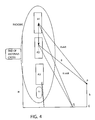
- FIG. 4 is a second embodiment of the invention which includes an additional antenna
- FIG. 5 is a block diagram of the electronic components associated with the design shown in FIG. 4 .
- the goal is to obtain in conjunction with a helicopter operating according to the ROSAR-system a quasi-three-dimensional radar image representation for flight guidance by associating with a transmitter located on the rotating rotary cross two coherent receiving antennas with receiving channels.
- the ROSAR-system used heretofore is comprised of, for example 16 transmitters and receivers with their channels for obtaining a three-dimensional image.
- these transmitters and receivers have a directional inaccuracy of about 2.5°.
- said ROSAR-system as mentioned above, is expanded by a highly precise coherent receiving channel, only one transmitter and two coherent receivers instead of the, for example sixteen transmitters and receivers employed until now will be required for obtaining the highly precise three-dimensional radar image.
- the directional inaccuracy found until now is enhanced by the interferometric principle by about a factor of 100.
- a helicopter operating according to the ROSAR principle flies over the surface of the earth at an altitude H.
- One transmitting antenna and two receiving antennas with associated coherent transmitting and receiving electronics are mounted on the end of the rotating antenna cross.
- the received echoes are amplified, digitized and processed further.
- the distance between this arrangement as described above, which is referred to in the following as the INROSAR-system, and the impact point P, which is located at a relative altitude h, is referred to as R.
- the distance from the antenna A 1 of the INROSAR-system to the impact point P amounts to R+ ⁇ R and is therefore by a small amount ⁇ R greater than the distance R to the antenna A 2 .
- the difference ⁇ R between the two distances can be calculated based on the known wavelength ⁇ of the emitted radar signal and the measured phase difference ⁇ of the receiving echo of the two coherent receiving channels.
- Impact point Q has a relative altitude lower than impact point P and is on the surface of the Earth E.
- this phase difference ⁇ of the receiving echo is in turn calculated based on the images generated by processing the receiving echo.
- Each of the two images is present in a complex, digital form, i.e. it comprises a real part and an imaginary part, or equivalent: the amplitude and the phase.
- phase difference ⁇ follows up to a multiple of p (modulo p) through complex multiplication of the image points of the one image with the conjugated complex image points of the other image, and subsequent formation of the arctangent of the respective real and imaginary parts.
- the phase difference ⁇ is obtained in this way, and by inserting ⁇ in equation 1, ⁇ R is then obtained.
- ⁇ ⁇ ⁇ R ⁇ 4 ⁇ ⁇ ⁇ ⁇ ( 1 )
- the altitude h is actually not required in connection with the INROSAR system for representing the image points on the graphics display screen DS, but only the sight angle ⁇ is used for calculating the coordinates of an impact point P on the integrated graphics display screen in the Rosar system. Furthermore, whether the angle of inclination of the antenna is known or not is unimportant as well because the representation on the display screen is only a relative representation of the image points with respect to the vertical line in relation to the base line B of the two antennas A 1 and A 2 . The representation of the image is in fact dependent upon the position of the helicopter, for example due to the pitching. However, the antennas of the INROSAR-system and the center of the image are always in a fixed relation to each other.
- the altitude h and the angle of inclination ⁇ of the antennas are only required if a topographical chart with an absolute altitude H of the area over which the aircraft is passing is to be generated with the help of said INROSAR-system.
- the formulas specified above are useful also for a consideration of errors, as will be explained in the following.
- the errors relevant to the INROSAR-system are the phase noise df and the change in the base line B between the phase centers of the antennas A 1 and A 2 .
- the phase noise is composed of the sum of proportions of the different components. The greatest contributions are supplied by the transmitter, the receivers, the system timer and the noise of the A/D-converter.
- a typical order of magnitude for the entire phase noise ⁇ of an INROSAR-system amounts to approximately 5°.
- the change in the base line between the phase centers of the antennas A 1 and A 2 may be caused, for example by heating due to the incidence of sunlight rays. 0.001 m is assumed to be a typical value.
- the helicopter flies in the normal position, which means that the antennas A 1 and A 2 are positioned vertically one on top of the other.
- ⁇ R is determined based on equation (1).
- the value of the measured phase difference ⁇ of the echo from the antennas A 1 , and A 2 is ambiguous and can be determined only down to a value ranging between 0 and 2 ⁇ . This ambiguity of 2 ⁇ has to be determined by means of additional measurements.
- an extra transmitter/receiver A 3 complementing the INROSAR conception comprising a transmitting/receiving antenna that has a narrow beam in elevation and covers the lower range of the sight angle can be used.
- the distance to the impact point on the ground can be clearly determined by the receive echo of this additional transmitting/receiving antenna.
- the INROSAR-system accepts the distance as a basic value and calculates the further ambiguities based on the rising distance from the continuous phase transitions. The following calculation example supplies the detailed explanations.
- the calculation is based on the situation that the helicopter flies in its normal position. This means that the antennas A 1 and A 2 are vertically arranged one on top of the other.
- FIG. 2 shows a block diagram of the exemplified embodiment shown in FIG. 1 .
- This block diagram is equipped with the components required for the proposed interferometric radar method and requires no further explanations for the expert in the field.
- transmitting antenna T 1 emits a signal that then reflects back as multiple signals including at least two received signals into Antennas A 1 and A 2 as signals Se 1 and Se 2 respectively. These signals are then fed into the electronic components as shown in FIG. 2 . In addition, data of the height H 0 is also fed into these electronic components.
- signals S e1 and S e2 are fed or decoupled into demodulator 1 and 2 respectively wherein they are then converted from analog signals into a digital signals in Analog Digital converters 1 and 2 respectively.
- the signals undergo a correction of movement errors via input from a kinematic sensor wherein this information is then fed into the respective memories 1 and 2 .
- This information is then processed in a correlator with range curvature correction wherein it is then processed in an interferometry module and then printed to an associated display screen.
- FIG. 3 shows a display of a rotating cross having an antenna lobe which is used to emit and receive signals.
- the antenna lobe can contain the two antennas and one transmitter as shown in FIG. 1 or it can contain the two transmitters and one antenna in FIG. 4 which also includes the additional sharply focused antenna which includes an additional transmitter and receiver.
- this additional sharply focused signal covers a lower region of the associated sight angle wherein as described above, this additional antenna A 3 including an additional transmitter and receiver is disposed adjacent to the other antennas A 1 and A 2 and the associated other transmitter T 1 .
- This additional antenna is for correlating and calculating the different ambiguities of the received signals in antennas A 1 and A 2 .
- the distance to the impact point on the ground can be clearly determined by the receive echo of this additional transmitting/receiving antenna.
- the INROSAR-system accepts the distance as a basic value and calculates the further ambiguities based on the rising distance from the continuous phase transitions.
- FIG. 5 shows the electronics design similar to that shown in FIG. 2 wherein this design includes the input from the additional antenna and receiver A 3 for additional processing.
- a coherent radar signal (See FIG. 4 ) is transmitted by one antenna A 1 and then received by two coherent receiving antennas A 1 and A 2 .
- the two coherent signals S e1 and S e2 are coherently demodulated in Demodulator 1 and Demodulator 2 and then converted from an analog signal to a digital signal in Analog to Digital converter (A/D) converter 1 and A/D converter 2 respectively.
- A/D Analog to Digital converter
- This information is then respectively fed into a system for the correction of movement errors.
- a kinematic sensor determines the movement of the helicopter (altitude and velocity) and feeds this information in the modules “Correction of Movement Errors 1 and 2 ”. These digital signals are then corrected and then written in Memory 1 and Memory 2 .
- a separate narrow beamed transmit/receive antenna supplies a signal S e3 which is converted from analog to digital as well.
- a distance module an unambiguous distance D 0 to the nearest illuminated point on the ground is determined.
- the distance D 0 and the altitude H 0 are supplied to the Geometry Module. This information is forwarded to the Depth of Focus Module and Distance Intervals Module.
- Both modules in combination with the Reference Functions Module calculate current valid reference functions. These reference functions are written to Memory 3 .
- the Range curvature comparator module determines the actual range curvature from the current helicopter movement and altitude.
- the reference functions from memory 3 and the current range curvature are fed in to the respective modules “Correlation with Range Curvature Correction 1 and 2 ” and corrected to reflect the current helicopter movement and altitude.
- the radar signals from Memory 1 and Memory 2 are also fed into the respective modules “Correlation with Range Curvature Correction 1 and 2 ”. Here they are correlated with the reference functions to give two 2 dimensional images 1 and 2 .
- the two respective images 1 and 2 are forwarded to the Interferometry Module, where the 3-dimensional image is calculated.
- the 3-dimensional image is transformed to a quasi-3 dimensional image so that it can be shown on a 2 dimensional display.
Abstract
It is proposed in connection with a method for the interferometric radar measurement in conjunction with a helicopter operating in accordance with the ROSAR principle (Heli-Radar) that two coherent receiving antennas with receiving channels are associated with a transmitter of the ROSAR-system mounted on the revolving rotary cross; and that the difference (ΔR) between the two distances (R+ΔR, R) from the measured impact point P are calculated, in the manner known per se, based on the wavelength λ of the emitted radar signal and the measured phase difference of the receiving echo of the two coherent receive channels.
Description
- This application is a continuation in part application of U.S. patent application Ser. No. 09/889,759 filed on Jul. 20, 2001, incorporated herein by reference wherein priority is claimed under 35 U.S.C. 120, this application also claims priority under 35 U.S.C. §371 from PCT/DE99/04066 filed on Dec. 22, 1999, and also claims priority under 35 U.S.C. 119 from German Patent Application DE 199020078 filed on Jan. 21, 1999.
- The invention relates to a method for interferometric radar measurements.
- Due to their construction, radar devices are precise range-finding systems, which means that without special measures, a radar device is capable of determining only the distance of a target from the antenna, but not its direction. It is possible to determine only whether a target is present within the lobe of the antenna.
- This problem is eliminated to a large extent in conjunction with the ROSAR or Heli-Radar system known until now by using, for example 16 vertically staggered antennas with an antenna opening angle of, for example 2.5°. It is possible with this type of a system to determine the location of an elevated obstruction etc. within an accuracy of about 2.5° in terms of elevation. However, in this case, targets located at the same distance are also displayed in the same antenna in the same image spot.
- The azimuthal resolution of the known Heli-Radar system amounts to about 0.2° because of a special signal processing. These features are taught in the disclosure in DE 39 22 086 C1. However, the direction of an obstruction and thus the location in space at which this obstruction is located can be determined only with the help of a triangulation, whereby in the simplest case, two locally separated radar installations can be used for this purpose.
- However, it is also possible to use the properties of a coherent radar system and to perform a triangulation with the help of the phase of the emitted signal. Thus, a coherent radar system is used which coherently transmits a signal via a transmitting antenna and receives the echoes scattered back via two locally separated receiving antennas. A coherent evaluation permits a calculation of the phase difference between receiving signals. The direction from which the scattered echoes are received is determined based on the phase difference. Now, once the distance and direction of an “obstruction” have been computed, its location in space can be determined as well. This type of three-dimensional determination of a location with the help of a coherent radar system which comprises one transmitting antenna and two receiving antennas is generally referred to as “radar interferometry” and known for a long time. It is used already for the generation of topographic charts with the help of SAR-systems installed on aircraft, for example by the DOSAR system of the firm Dornier GmbH.
- With these designs, reference is also made to the following published documents pertaining to the further state of the art:
- C. T. Allan, Review Article, Interferometric Synthetic Aperture Radar, in IEEE Geoscience and Remote Sensing Society News Letter, September 1995, p. 6 ff; S. Buckreuss, J. Moreira, H. Rinkel and G. Waller, Advanced SAR Interferometry Study, DLR Bulletin 94, Jun. 10, 1994, Institut für Hochfrequenztechnik, Oberpfaffenhofen.
- The entire prior art known to this date and the state of the art cited above, including the ROSAR principle on which the present invention is based, projects terrain elevations or other elevated obstructions in one plane, so that it is not possible to recognize the elevation of the given obstruction if the reproduced topography of the terrain present is unknown. However, a three-dimensional image is required for controlling flights.
- The present invention is based on the problem of proposing measures on the basis of the ROSAR principle that permit a quasi-three-dimensional image representation of terrain and other obstructions.
- The problem is solved with an arrangement for interferometric radar measurement having a transmitter and two assigned coherent receiving antennas with receiving channels. The transmitter and receiving antennas are arranged on the turnstile of the ROSAR system of a helicopter radar. An additional transmitting/receiving antenna is provided wherein this additional transmitting/receiving antenna is sharply focused in the elevation direction. The transmitter and receiving antennas are arranged at the end of the turnstile. The receiving antennas are also arranged at the end of the turnstile.
- The arrangement includes a process whereby two coherent receiving antennas with receiving channels are assigned to a first transmitter, and the path length difference of the two distances can be calculated to measured receiving point P from the wave length of the transmitted radar signal and of the measured phase difference of the reception echo of both coherent receiving channels. A helicopter operating according to the ROSAR principle is used for the interferometric radar measurement, whereby two coherent receiving antennas are assigned to a transmitter of the ROSAR system arranged on a rotating turnstile on the radar. Additionally, receiving signals of the sharply focused or second transmitting/receiving antenna can be evaluated for determination of the phase difference.
- The sight angle is used for calculating the coordinates of the respective receiving point for representing the image points on the integrated graphic display screen in the ROSAR system. The antennas and the center of the image on the graphic display screen are in a fixed relationship to each other.
- The first transmitter along with the two receiving antennas are used to determine the location of point P. However, this determination of the location of point P may contain inaccuracies or ambiguities because these two receiving antennas have a value of a measured phase difference that is ambiguous wherein this ambiguity can only be determined down to a value ranging between 0 and 2π. Therefore, this ambiguity must be determined by additional measurements. Thus to provide these additional measurements there is the additional or sharply focused transmitting and receiving antenna. This transmitting and receiving antenna is located in the end of the antenna cross and wherein this antenna has a narrow beam. This antenna covers the lower range of the sight angle. The distance to the impact point on the ground can be clearly determined by the receive echo of this additional transmitting/receiving antenna. Thus, this INROSAR-system accepts the distance as a basic value and calculates the further ambiguities based on the rising distance from the continuous phase transitions.
- Thus, this system is a system with a first antenna transmitter with two receiving antennas and then one additional transmitting and receiving antenna that is used to dispel any ambiguities of the signal received by the first antenna transmitter and receiver.
- Other objects and features of the present invention will become apparent from the following detailed description considered in connection with the accompanying drawings which disclose at least one embodiment of the present invention. It should be understood, however, that the drawings are designed for the purpose of illustration only and not as a definition of the limits of the invention.
- In the drawings, wherein similar reference characters denote similar elements throughout the several views:
-
FIG. 1 shows a schematic representation of an exemplified embodiment with respect to the typical geometry for an interferometric ROSAR system; -
FIG. 2 shows a block diagram of the exemplified embodiment according toFIG. 1 ; -
FIG. 3 is a perspective view of the state of the art with respect to the ROSAR principle; -
FIG. 4 is a second embodiment of the invention which includes an additional antenna; and -
FIG. 5 is a block diagram of the electronic components associated with the design shown inFIG. 4 . - According to the general idea of the invention, the goal is to obtain in conjunction with a helicopter operating according to the ROSAR-system a quasi-three-dimensional radar image representation for flight guidance by associating with a transmitter located on the rotating rotary cross two coherent receiving antennas with receiving channels.
- The ROSAR-system used heretofore is comprised of, for example 16 transmitters and receivers with their channels for obtaining a three-dimensional image. However, these transmitters and receivers have a directional inaccuracy of about 2.5°. Now, if said ROSAR-system, as mentioned above, is expanded by a highly precise coherent receiving channel, only one transmitter and two coherent receivers instead of the, for example sixteen transmitters and receivers employed until now will be required for obtaining the highly precise three-dimensional radar image. The directional inaccuracy found until now is enhanced by the interferometric principle by about a factor of 100.
- This is explained in the following description of an exemplified embodiment of the invention, which is sketched in
FIG. 1 . - A helicopter operating according to the ROSAR principle flies over the surface of the earth at an altitude H. One transmitting antenna and two receiving antennas with associated coherent transmitting and receiving electronics are mounted on the end of the rotating antenna cross. The received echoes are amplified, digitized and processed further.
- The distance between this arrangement as described above, which is referred to in the following as the INROSAR-system, and the impact point P, which is located at a relative altitude h, is referred to as R. The distance from the antenna A1 of the INROSAR-system to the impact point P amounts to R+ΔR and is therefore by a small amount ΔR greater than the distance R to the antenna A2. The difference ΔR between the two distances can be calculated based on the known wavelength λ of the emitted radar signal and the measured phase difference φ of the receiving echo of the two coherent receiving channels. Impact point Q has a relative altitude lower than impact point P and is on the surface of the Earth E.
- Now, this phase difference φ of the receiving echo is in turn calculated based on the images generated by processing the receiving echo. Each of the two images is present in a complex, digital form, i.e. it comprises a real part and an imaginary part, or equivalent: the amplitude and the phase.
- Now, the phase difference φ follows up to a multiple of p (modulo p) through complex multiplication of the image points of the one image with the conjugated complex image points of the other image, and subsequent formation of the arctangent of the respective real and imaginary parts. The phase difference φ is obtained in this way, and by inserting φ in
equation 1, ΔR is then obtained. - The phase centers of the two receiving antennas A1 and A2 are removed by the length B, the so-called base line. The following results from the cosinus theorem and a few simple angle relations:
- After the sight angle θ has been calculated in equation (2), it is now possible to determine the relative altitude h as follows:
h=H−R·cos(θ) (3) - The altitude h is actually not required in connection with the INROSAR system for representing the image points on the graphics display screen DS, but only the sight angle θ is used for calculating the coordinates of an impact point P on the integrated graphics display screen in the Rosar system. Furthermore, whether the angle of inclination of the antenna is known or not is unimportant as well because the representation on the display screen is only a relative representation of the image points with respect to the vertical line in relation to the base line B of the two antennas A1 and A2. The representation of the image is in fact dependent upon the position of the helicopter, for example due to the pitching. However, the antennas of the INROSAR-system and the center of the image are always in a fixed relation to each other. The altitude h and the angle of inclination α of the antennas are only required if a topographical chart with an absolute altitude H of the area over which the aircraft is passing is to be generated with the help of said INROSAR-system. The formulas specified above are useful also for a consideration of errors, as will be explained in the following.
- The errors relevant to the INROSAR-system are the phase noise df and the change in the base line B between the phase centers of the antennas A1 and A2. The phase noise is composed of the sum of proportions of the different components. The greatest contributions are supplied by the transmitter, the receivers, the system timer and the noise of the A/D-converter. A typical order of magnitude for the entire phase noise δφ of an INROSAR-system amounts to approximately 5°. The change in the base line between the phase centers of the antennas A1 and A2 may be caused, for example by heating due to the incidence of sunlight rays. 0.001 m is assumed to be a typical value. The various influences result in a scatter δh of the altitude of the impact point P and thus in a scatter of the sight angle δθ.
- This results in scatter of the sight angle dθ as follows:
- In conjunction with an exemplified embodiment according to
FIG. 1 , the helicopter flies in the normal position, which means that the antennas A1 and A2 are positioned vertically one on top of the other. ΔR is determined based on equation (1). The value of the measured phase difference Δφ of the echo from the antennas A1, and A2 is ambiguous and can be determined only down to a value ranging between 0 and 2π. This ambiguity of 2π has to be determined by means of additional measurements. Thus, as shown inFIG. 4 an extra transmitter/receiver A3 complementing the INROSAR conception comprising a transmitting/receiving antenna that has a narrow beam in elevation and covers the lower range of the sight angle can be used. The distance to the impact point on the ground can be clearly determined by the receive echo of this additional transmitting/receiving antenna. The INROSAR-system accepts the distance as a basic value and calculates the further ambiguities based on the rising distance from the continuous phase transitions. The following calculation example supplies the detailed explanations. - The calculation is based on the situation that the helicopter flies in its normal position. This means that the antennas A1 and A2 are vertically arranged one on top of the other.
- The following parameters apply:
Parameter Meaning Value 1/Value 2 H flight altitude of INROSAR 100 m R + ΔR Distance between impact point P and Example 1: 500.009 m antenna A1 Example 2: 500.09 m R Distance between impact point P and 500.00 m antenna A2 B Base line between the phase centers 0.15 m of the antennas δB Error of length of base line B 0.001 m δφ Phase noise of the INROSAR system 5° α Angle in inclination of antennas A1 90° (vertically) and A2 λ Radar wavelength 0.0090909 - From equation (2) follows:
-
-
- From the equations (4) and (5) follows for the scatter δh of the altitude h of the impact point P:
- This results in a scatter of the sight angle δθ as follows:
- Due to phase noise, δφ=5°:
and because of errors in the length of base line B by δB=0.001 m: -
FIG. 2 shows a block diagram of the exemplified embodiment shown inFIG. 1 . This block diagram is equipped with the components required for the proposed interferometric radar method and requires no further explanations for the expert in the field. - However, the process is as follows, transmitting antenna T1 emits a signal that then reflects back as multiple signals including at least two received signals into Antennas A1 and A2 as signals Se1 and Se2 respectively. These signals are then fed into the electronic components as shown in
FIG. 2 . In addition, data of the height H0 is also fed into these electronic components. - These signals Se1 and Se2 are fed or decoupled into
demodulator Analog Digital converters respective memories -
FIG. 3 shows a display of a rotating cross having an antenna lobe which is used to emit and receive signals. The antenna lobe can contain the two antennas and one transmitter as shown inFIG. 1 or it can contain the two transmitters and one antenna inFIG. 4 which also includes the additional sharply focused antenna which includes an additional transmitter and receiver. - As shown in
FIG. 4 this additional sharply focused signal covers a lower region of the associated sight angle wherein as described above, this additional antenna A3 including an additional transmitter and receiver is disposed adjacent to the other antennas A1 and A2 and the associated other transmitter T1. This additional antenna is for correlating and calculating the different ambiguities of the received signals in antennas A1 and A2. The distance to the impact point on the ground can be clearly determined by the receive echo of this additional transmitting/receiving antenna. The INROSAR-system accepts the distance as a basic value and calculates the further ambiguities based on the rising distance from the continuous phase transitions. - Finally,
FIG. 5 shows the electronics design similar to that shown inFIG. 2 wherein this design includes the input from the additional antenna and receiver A3 for additional processing. - For example, a coherent radar signal (See
FIG. 4 ) is transmitted by one antenna A1 and then received by two coherent receiving antennas A1 and A2. The two coherent signals Se1 and Se2 are coherently demodulated inDemodulator 1 andDemodulator 2 and then converted from an analog signal to a digital signal in Analog to Digital converter (A/D)converter 1 and A/D converter 2 respectively. This information is then respectively fed into a system for the correction of movement errors. In addition, a kinematic sensor determines the movement of the helicopter (altitude and velocity) and feeds this information in the modules “Correction ofMovement Errors Memory 1 andMemory 2. - A separate narrow beamed transmit/receive antenna supplies a signal Se3 which is converted from analog to digital as well. In addition, in a distance module, an unambiguous distance D0 to the nearest illuminated point on the ground is determined. The distance D0 and the altitude H0 are supplied to the Geometry Module. This information is forwarded to the Depth of Focus Module and Distance Intervals Module. Both modules in combination with the Reference Functions Module calculate current valid reference functions. These reference functions are written to
Memory 3. The Range curvature comparator module determines the actual range curvature from the current helicopter movement and altitude. The reference functions frommemory 3 and the current range curvature are fed in to the respective modules “Correlation withRange Curvature Correction - The radar signals from
Memory 1 andMemory 2 are also fed into the respective modules “Correlation withRange Curvature Correction dimensional images respective images - Thus, with this additional signal Se3 is used to clarify any ambiguities associated with the measurement of the other two signals Se1 and Se2 that are read by antennas A1 and A2.
- Accordingly, while at least one embodiment of the present invention has been shown and described, it is to be understood that many changes and modifications may be made thereunto without departing from the spirit and scope of the invention as defined in the appended claims.
Claims (6)
1. An arrangement for interferometric radar measurement comprising:
a transmitter disposed on a turnstile of a ROSAR system of a helicopter radar;
at least two assigned coherent receiving antennas having receiving channels disposed on said turnstile of said ROSAR system of a helicopter radar; and
an additional transmitting/receiving antenna disposed on said turnstile wherein said additional transmitting/receiving antenna has a narrow beam and is focused downward in elevation covering a lower range of a sight angle.
2. The arrangement for interferometric radar measurement according to claim 1 , wherein said transmitter and said at least two assigned coherent receiving antennas are arranged at an end of said turnstile.
3. The arrangement for interferometric radar measurement according to claim 1 , wherein said receiving antennas are positioned vertically over each other in a normal position of a helicopter.
4. A process for interferometric radar measurement comprising the steps of:
assigning two coherent receiving antennas having receiving channels to a transmitter;
calculating a path length difference of two distances to a measured receiving point from a wave length of a transmitted radar signal and of a measured phase difference of a reception echo of both coherent receiving channels;
assigning said two coherent receiving antennas to a transmitter of a ROSAR system;
arranging said two coherent receiving antennas and said transmitter on a rotating turnstile of a radar; and
evaluating signals of an additional transmitting/receiving antenna that has a narrow beam and is for determination of said phase difference of said reception echo of both coherent receiving channels;
wherein a helicopter operating according to the ROSAR principle is used for the interferometric radar measurement.
5. The method according to claim 4 , further comprising a step of calculating coordinates of a respective receiving point using a sight angle for representing image points on an integrated graphic display screen in the ROSAR system.
6. The method according to claim 5 , wherein said antenna and a center of an image on said graphic display screen are in a fixed relationship.
Priority Applications (1)
| Application Number | Priority Date | Filing Date | Title |
|---|---|---|---|
| US10/770,830 US7002508B2 (en) | 1999-01-21 | 2004-02-03 | Method for interferometric radar measurement |
Applications Claiming Priority (5)
| Application Number | Priority Date | Filing Date | Title |
|---|---|---|---|
| DE19902007.8 | 1999-01-21 | ||
| DE19902007A DE19902007C2 (en) | 1999-01-21 | 1999-01-21 | Method and arrangement for interferometric radar measurement |
| PCT/DE1999/004066 WO2000043808A1 (en) | 1999-01-21 | 1999-12-22 | Method for interferometrical radar measurement |
| US88975901A | 2001-07-20 | 2001-07-20 | |
| US10/770,830 US7002508B2 (en) | 1999-01-21 | 2004-02-03 | Method for interferometric radar measurement |
Related Parent Applications (3)
| Application Number | Title | Priority Date | Filing Date |
|---|---|---|---|
| US09889759 Continuation-In-Part | 1999-12-22 | ||
| PCT/DE1999/004066 Continuation-In-Part WO2000043808A1 (en) | 1999-01-21 | 1999-12-22 | Method for interferometrical radar measurement |
| US88975901A Continuation-In-Part | 1999-01-21 | 2001-07-20 |
Publications (2)
| Publication Number | Publication Date |
|---|---|
| US20050128126A1 true US20050128126A1 (en) | 2005-06-16 |
| US7002508B2 US7002508B2 (en) | 2006-02-21 |
Family
ID=34654916
Family Applications (1)
| Application Number | Title | Priority Date | Filing Date |
|---|---|---|---|
| US10/770,830 Expired - Fee Related US7002508B2 (en) | 1999-01-21 | 2004-02-03 | Method for interferometric radar measurement |
Country Status (1)
| Country | Link |
|---|---|
| US (1) | US7002508B2 (en) |
Cited By (9)
| Publication number | Priority date | Publication date | Assignee | Title |
|---|---|---|---|---|
| US7002508B2 (en) * | 1999-01-21 | 2006-02-21 | Eads Deutschland Gmbh | Method for interferometric radar measurement |
| US7551119B1 (en) * | 2008-01-08 | 2009-06-23 | Sandia Corporation | Flight path-driven mitigation of wavefront curvature effects in SAR images |
| WO2011101794A2 (en) | 2010-02-22 | 2011-08-25 | Elbit Systems Ltd. | Three dimensional radar system |
| CN103364784A (en) * | 2013-07-22 | 2013-10-23 | 武汉大学 | Looking-around synthetic aperture imaging radar |
| US20150177377A1 (en) * | 2012-06-11 | 2015-06-25 | BRADAR INDUSTRIA S.A. (formerly known as ORBISAT INDÚSTRIA E AEROLEVANTAMENTO S/A | Weather radar system |
| EP3173814A1 (en) * | 2015-11-27 | 2017-05-31 | Bradar Industria S.A. | System and method for detecting and visualizing targets by airborne radar |
| US9933519B2 (en) | 2010-02-22 | 2018-04-03 | Elbit Systems Ltd. | Three dimensional radar system |
| IT201600127152A1 (en) * | 2016-12-15 | 2018-06-15 | Ids Georadar S R L | Method and equipment for monitoring surface deformations of a scenario |
| US11353580B2 (en) * | 2018-12-20 | 2022-06-07 | Thales | Proximity radar method and system for a rotary-wing aircraft |
Families Citing this family (5)
| Publication number | Priority date | Publication date | Assignee | Title |
|---|---|---|---|---|
| US7528762B2 (en) * | 2005-03-31 | 2009-05-05 | Southwest Research Institute | Signal processing methods for ground penetrating radar from elevated platforms |
| US8960593B2 (en) * | 2011-05-03 | 2015-02-24 | Raytheon Company | Horizon scanning system for a rotary wing aircraft including sensors housed within a tubercle on a rotor blade |
| EP3312631B1 (en) * | 2012-12-10 | 2020-08-12 | AIRBUS HELICOPTERS DEUTSCHLAND GmbH | A rotorcraft with an obstacle and terrain warning radar system |
| US9128184B1 (en) * | 2013-03-14 | 2015-09-08 | Lockheed Martin Corporation | Radar wind turbine |
| RU2560082C2 (en) * | 2014-01-09 | 2015-08-20 | Федеральное государственное автономное образовательное учреждение высшего профессионального образования "Санкт-Петербургский государственный университет аэрокосмического приборостроения" | Method for frontal earth surface aperture synthesis with exclusion of blind zones in front zone using multi-position radar system |
Citations (11)
| Publication number | Priority date | Publication date | Assignee | Title |
|---|---|---|---|---|
| US4546354A (en) * | 1982-06-17 | 1985-10-08 | Grumman Aerospace Corporation | Range/azimuth ship imaging for ordnance control |
| US4638315A (en) * | 1984-06-20 | 1987-01-20 | Westinghouse Electric Corp. | Rotor tip synthetic aperture radar |
| US5017922A (en) * | 1989-07-05 | 1991-05-21 | Messerschmitt-Bolkow-Blohm Gmbh | Radar system having a synthetic aperture on the basis of rotating antennae |
| US5160931A (en) * | 1991-09-19 | 1992-11-03 | Environmental Research Institute Of Michigan | Interferometric synthetic aperture detection of sparse non-surface objects |
| US5392047A (en) * | 1992-12-16 | 1995-02-21 | Deutsch Aerospace Ag | Radar device comprising a synthetic aperture on the basis of rotating antennas |
| US5451957A (en) * | 1993-07-14 | 1995-09-19 | Daimler-Benz Aerospace Ag | Radar device for obstacle warning |
| US5614907A (en) * | 1996-03-14 | 1997-03-25 | Daimler-Benz Aerospace Ag | All weather visual system for helicopters |
| US5659318A (en) * | 1996-05-31 | 1997-08-19 | California Institute Of Technology | Interferometric SAR processor for elevation |
| US5777573A (en) * | 1995-08-04 | 1998-07-07 | Daimler-Benz Aerospace Ag | Device for motion error compensation for a radar with synthetic aperture based on rotating antennas (ROSAR) for helicopters |
| US6166677A (en) * | 1998-07-31 | 2000-12-26 | Nec Corporation | Image synthesizing method using a plurality of reflection radar waves and aircraft image radar apparatus using the method |
| US6577264B1 (en) * | 1999-09-24 | 2003-06-10 | Eads Deutschland Gmbh | Helicopter-borne radar system |
Family Cites Families (4)
| Publication number | Priority date | Publication date | Assignee | Title |
|---|---|---|---|---|
| DE4306920C2 (en) | 1993-03-05 | 1995-03-30 | Deutsche Aerospace | Radar device with synthetic aperture based on rotating antennas |
| DE4328573C2 (en) | 1993-08-25 | 1995-12-14 | Daimler Benz Aerospace Ag | All-weather vision system for helicopters |
| DE19902007C2 (en) * | 1999-01-21 | 2002-06-27 | Daimler Chrysler Ag | Method and arrangement for interferometric radar measurement |
| US7002508B2 (en) * | 1999-01-21 | 2006-02-21 | Eads Deutschland Gmbh | Method for interferometric radar measurement |
-
2004
- 2004-02-03 US US10/770,830 patent/US7002508B2/en not_active Expired - Fee Related
Patent Citations (11)
| Publication number | Priority date | Publication date | Assignee | Title |
|---|---|---|---|---|
| US4546354A (en) * | 1982-06-17 | 1985-10-08 | Grumman Aerospace Corporation | Range/azimuth ship imaging for ordnance control |
| US4638315A (en) * | 1984-06-20 | 1987-01-20 | Westinghouse Electric Corp. | Rotor tip synthetic aperture radar |
| US5017922A (en) * | 1989-07-05 | 1991-05-21 | Messerschmitt-Bolkow-Blohm Gmbh | Radar system having a synthetic aperture on the basis of rotating antennae |
| US5160931A (en) * | 1991-09-19 | 1992-11-03 | Environmental Research Institute Of Michigan | Interferometric synthetic aperture detection of sparse non-surface objects |
| US5392047A (en) * | 1992-12-16 | 1995-02-21 | Deutsch Aerospace Ag | Radar device comprising a synthetic aperture on the basis of rotating antennas |
| US5451957A (en) * | 1993-07-14 | 1995-09-19 | Daimler-Benz Aerospace Ag | Radar device for obstacle warning |
| US5777573A (en) * | 1995-08-04 | 1998-07-07 | Daimler-Benz Aerospace Ag | Device for motion error compensation for a radar with synthetic aperture based on rotating antennas (ROSAR) for helicopters |
| US5614907A (en) * | 1996-03-14 | 1997-03-25 | Daimler-Benz Aerospace Ag | All weather visual system for helicopters |
| US5659318A (en) * | 1996-05-31 | 1997-08-19 | California Institute Of Technology | Interferometric SAR processor for elevation |
| US6166677A (en) * | 1998-07-31 | 2000-12-26 | Nec Corporation | Image synthesizing method using a plurality of reflection radar waves and aircraft image radar apparatus using the method |
| US6577264B1 (en) * | 1999-09-24 | 2003-06-10 | Eads Deutschland Gmbh | Helicopter-borne radar system |
Cited By (18)
| Publication number | Priority date | Publication date | Assignee | Title |
|---|---|---|---|---|
| US7002508B2 (en) * | 1999-01-21 | 2006-02-21 | Eads Deutschland Gmbh | Method for interferometric radar measurement |
| US7551119B1 (en) * | 2008-01-08 | 2009-06-23 | Sandia Corporation | Flight path-driven mitigation of wavefront curvature effects in SAR images |
| US9933519B2 (en) | 2010-02-22 | 2018-04-03 | Elbit Systems Ltd. | Three dimensional radar system |
| WO2011101794A2 (en) | 2010-02-22 | 2011-08-25 | Elbit Systems Ltd. | Three dimensional radar system |
| US20130069819A1 (en) * | 2010-02-22 | 2013-03-21 | Elbit Systems Ltd. | Three dimensional radar system |
| US8981990B2 (en) * | 2010-02-22 | 2015-03-17 | Elbit Systems Ltd. | Three dimensional radar system |
| WO2011101794A3 (en) * | 2010-02-22 | 2015-09-11 | Elbit Systems Ltd. | Three dimensional radar system |
| US20150177377A1 (en) * | 2012-06-11 | 2015-06-25 | BRADAR INDUSTRIA S.A. (formerly known as ORBISAT INDÚSTRIA E AEROLEVANTAMENTO S/A | Weather radar system |
| US9817115B2 (en) * | 2012-06-11 | 2017-11-14 | Bradar Industria S.A. | Weather radar system |
| CN103364784A (en) * | 2013-07-22 | 2013-10-23 | 武汉大学 | Looking-around synthetic aperture imaging radar |
| EP3173814A1 (en) * | 2015-11-27 | 2017-05-31 | Bradar Industria S.A. | System and method for detecting and visualizing targets by airborne radar |
| US10495751B2 (en) | 2015-11-27 | 2019-12-03 | Bradar Industria S.A. | System and method for detecting and visualizing targets by airborne radar |
| IT201600127152A1 (en) * | 2016-12-15 | 2018-06-15 | Ids Georadar S R L | Method and equipment for monitoring surface deformations of a scenario |
| WO2018109745A1 (en) * | 2016-12-15 | 2018-06-21 | Ids Georadar S.R.L. | Method and apparatus for monitoring surface deformations of a scenario |
| CN110691987A (en) * | 2016-12-15 | 2020-01-14 | 入侵检测雷达公司 | Method and apparatus for monitoring surface deformation of a scene |
| US11320533B2 (en) * | 2016-12-15 | 2022-05-03 | Ids Georadar S.R.L. | Method and apparatus for monitoring surface deformations of a scenario |
| AU2017378441B2 (en) * | 2016-12-15 | 2022-06-16 | Ids Georadar S.R.L. | Method and apparatus for monitoring surface deformations of a scenario |
| US11353580B2 (en) * | 2018-12-20 | 2022-06-07 | Thales | Proximity radar method and system for a rotary-wing aircraft |
Also Published As
| Publication number | Publication date |
|---|---|
| US7002508B2 (en) | 2006-02-21 |
Similar Documents
| Publication | Publication Date | Title |
|---|---|---|
| US7298325B2 (en) | Technique for accurate estimate of large antenna inertial two dimensional orientation using relative GPS spatial phase | |
| EP1774257B1 (en) | Combination laser system and global navigation satellite system | |
| US7002508B2 (en) | Method for interferometric radar measurement | |
| CA2114528C (en) | Three dimensional interferometric synthetic aperture radar terrain mapping employing altitude measurement | |
| US5867119A (en) | Precision height measuring device | |
| US5189424A (en) | Three dimensional interferometric synthetic aperture radar terrain mapping employing altitude measurement and second order correction | |
| US8705022B2 (en) | Navigation system using both GPS and laser reference | |
| US7167126B2 (en) | Radar system and method for determining the height of an object | |
| US6462699B2 (en) | Bistatic radar system for centralized, near-real-time synchronized, processing of data to identify scatterers | |
| US20040178943A1 (en) | Obstacle and terrain avoidance sensor | |
| US11454702B2 (en) | Synthetic aperture radar method and synthetic aperture radar device | |
| CN106526583B (en) | A kind of ground moving object localization method based on antenna radiation pattern information | |
| EP1279970A2 (en) | A system for monitoring a feature of a surface with broad swath and high resolution | |
| US6456229B2 (en) | Bistatic radar network having incoherent transmitter operating in a scanning mode to identify scatterers | |
| JPH045157B2 (en) | ||
| US6741202B1 (en) | Techniques for 3-dimensional synthetic aperture radar | |
| US6853330B1 (en) | Inverse precision velocity update for monopulse calibration | |
| Yang et al. | On the value of corner reflectors and surface models in InSAR precise point positioning | |
| US6208283B1 (en) | Synthetic aperture radar system and platform position measuring apparatus used in the same | |
| KR100441590B1 (en) | Method of generating DEM for Topography Measurement using InSAR | |
| US6664917B2 (en) | Synthetic aperture, interferometric, down-looking, imaging, radar system | |
| US6515613B2 (en) | Rosar method for landing helicopters under adverse weather conditions and for recognizing and detecting concealed targets | |
| CA2359331A1 (en) | Method for interferometrical radar measurement | |
| Zink et al. | Calibration of the Interferometric X-SAR System on SRTM | |
| US7136014B2 (en) | System and method for estimating the azimuth pointing angle of a moving monopulse antenna |
Legal Events
| Date | Code | Title | Description |
|---|---|---|---|
| AS | Assignment |
Owner name: EADS DEUTSCHLAND GMBH, GERMANY Free format text: ASSIGNMENT OF ASSIGNORS INTEREST;ASSIGNORS:WOLFRAMM, ARIBERT P.;KLAUSING, HELMUT;REEL/FRAME:015522/0258 Effective date: 20040621 |
|
| FEPP | Fee payment procedure |
Free format text: PAYOR NUMBER ASSIGNED (ORIGINAL EVENT CODE: ASPN); ENTITY STATUS OF PATENT OWNER: LARGE ENTITY |
|
| REMI | Maintenance fee reminder mailed | ||
| LAPS | Lapse for failure to pay maintenance fees | ||
| STCH | Information on status: patent discontinuation |
Free format text: PATENT EXPIRED DUE TO NONPAYMENT OF MAINTENANCE FEES UNDER 37 CFR 1.362 |
|
| FP | Lapsed due to failure to pay maintenance fee |
Effective date: 20100221 |