US20050217841A1 - Heat flux measuring device for pressure pipes, method for producing a measuring device, method for monitoring an operating state of a heat exchanger, heat exchanger and method for measuring a heat flux - Google Patents
Heat flux measuring device for pressure pipes, method for producing a measuring device, method for monitoring an operating state of a heat exchanger, heat exchanger and method for measuring a heat flux Download PDFInfo
- Publication number
- US20050217841A1 US20050217841A1 US11/108,438 US10843805A US2005217841A1 US 20050217841 A1 US20050217841 A1 US 20050217841A1 US 10843805 A US10843805 A US 10843805A US 2005217841 A1 US2005217841 A1 US 2005217841A1
- Authority
- US
- United States
- Prior art keywords
- measuring device
- indentation
- heat exchanger
- pressure pipe
- thermocouple
- Prior art date
- Legal status (The legal status is an assumption and is not a legal conclusion. Google has not performed a legal analysis and makes no representation as to the accuracy of the status listed.)
- Granted
Links
Images

Classifications
-
- G—PHYSICS
- G01—MEASURING; TESTING
- G01K—MEASURING TEMPERATURE; MEASURING QUANTITY OF HEAT; THERMALLY-SENSITIVE ELEMENTS NOT OTHERWISE PROVIDED FOR
- G01K17/00—Measuring quantity of heat
- G01K17/06—Measuring quantity of heat conveyed by flowing media, e.g. in heating systems e.g. the quantity of heat in a transporting medium, delivered to or consumed in an expenditure device
- G01K17/08—Measuring quantity of heat conveyed by flowing media, e.g. in heating systems e.g. the quantity of heat in a transporting medium, delivered to or consumed in an expenditure device based upon measurement of temperature difference or of a temperature
- G01K17/20—Measuring quantity of heat conveyed by flowing media, e.g. in heating systems e.g. the quantity of heat in a transporting medium, delivered to or consumed in an expenditure device based upon measurement of temperature difference or of a temperature across a radiating surface, combined with ascertainment of the heat transmission coefficient
-
- F—MECHANICAL ENGINEERING; LIGHTING; HEATING; WEAPONS; BLASTING
- F28—HEAT EXCHANGE IN GENERAL
- F28F—DETAILS OF HEAT-EXCHANGE AND HEAT-TRANSFER APPARATUS, OF GENERAL APPLICATION
- F28F27/00—Control arrangements or safety devices specially adapted for heat-exchange or heat-transfer apparatus
-
- G—PHYSICS
- G01—MEASURING; TESTING
- G01K—MEASURING TEMPERATURE; MEASURING QUANTITY OF HEAT; THERMALLY-SENSITIVE ELEMENTS NOT OTHERWISE PROVIDED FOR
- G01K1/00—Details of thermometers not specially adapted for particular types of thermometer
- G01K1/14—Supports; Fastening devices; Arrangements for mounting thermometers in particular locations
- G01K1/143—Supports; Fastening devices; Arrangements for mounting thermometers in particular locations for measuring surface temperatures
-
- Y—GENERAL TAGGING OF NEW TECHNOLOGICAL DEVELOPMENTS; GENERAL TAGGING OF CROSS-SECTIONAL TECHNOLOGIES SPANNING OVER SEVERAL SECTIONS OF THE IPC; TECHNICAL SUBJECTS COVERED BY FORMER USPC CROSS-REFERENCE ART COLLECTIONS [XRACs] AND DIGESTS
- Y10—TECHNICAL SUBJECTS COVERED BY FORMER USPC
- Y10T—TECHNICAL SUBJECTS COVERED BY FORMER US CLASSIFICATION
- Y10T29/00—Metal working
- Y10T29/49—Method of mechanical manufacture
- Y10T29/4935—Heat exchanger or boiler making
Definitions
- the present invention relates to a measuring device for pressure pipes of a heat exchanger or heating boiler including a pressure pipe and at least one thermocouple.
- the invention also relates to a method for producing a measuring device for pressure pipes, a method for monitoring an operating state of a heat exchanger having a pressure pipe, a heat exchanger, and a method for measuring a heat flux.
- the thermal energy that is produced when the fuel is burnt is conventionally used to heat water flowing in pressure pipes.
- the heated water is used, for example, to produce steam and to drive a steam turbine.
- the efficiency of heating boilers of that type or of heat exchangers is determined, in particular, by the contamination of the outside and the inside of the pressure pipes. For example, combustion residues on the outside of the pipes cause the heating resistance of the pipes to increase and prevent a heat flux from the combustion chamber to the water. Increased heat resistance means that only a small portion of the heat from the water to be transferred may be received and converted into electrical energy.
- the conditions under which heat flux measurements on lines conveying high-pressure steam have to be carried out are especially problematic, in particular with regard to the high temperatures that are encountered.
- the high pressure also stresses the pressure pipes from the inside.
- the heat flux (expressed in W/m 2 ) is measured through the heat exchanger surface through the use of a heat flux sensor. That information can be used to study the behavior of the heating boiler or heat exchanger, to control a combustion chamber, to guide a water lance blower and to detect the contamination of heat exchanger surfaces.
- the general requirements for a heat flux sensor on pressure pipes are the stability, the strength and the reliability of the sensors under the respective conditions. Moreover, the sensors should influence the heat flux as little as possible, i.e. operation, size and dimensions thereof should influence the measured variable as little as possible. The sensors should also cause the pressure pipe surface to overheat as little as possible. They should impede the flow of the pressure medium as little as possible. For the sake of reliability, it is expedient to configure the sensors in such a way that they may be redundantly disposed.
- Thickened pressure pipe sensors are usually produced from a conventional pressure pipe in such a way that the pipe is provided with an indentation, in order to provide space for a sensor.
- the local indentation is filled with filling material, typically with welding material.
- the filling material is mechanically treated in such a way that a sensor may be embedded.
- a first, important aspect is that the pressure pipe wall temperature (and therefore the temperature of the sensor) is lower than the maximum permitted temperature for the pressure pipe and the sensor.
- This critical value is material-specific and may, for example, be about 600° C. Operating the system above 600° then rapidly impairs the efficiency of the pressure pipe and the sensor, so that the operation of the heating boiler is threatened by a malfunction of the pressure pipes.
- the pressure pipes exhibit, for example, wall thicknesses of between 4 mm and 10 mm and may advantageously be made of various molybdenum steel alloys. For example, at a steam temperature of 420° C. and a heat flux of approximately 250 kW/m 2 and a 6 mm wall thickness, the outer wall temperature is about 450° C.
- a heat flux sensor which conventionally has an overall height of between 5 and 8 mm, is incorporated onto or into a pressure pipe of that type, the outside temperature of the pressure pipes, with the same heat flux and same steam temperature, remains, for example, at approximately 530° C., if typical material values are assumed.
- the surface of the pressure pipe at the sensor easily reaches the critical temperature of 600° C. That shows that the thermal resistance of the heat flux sensor may not be ignored and therefore has to be reduced.
- the definitive factor for reducing the size of the indentation is, on one hand, the sensitivity of the sensor and, on the other hand, the possibility of guiding the electrical lines of the sensor, from the sensor out of the combustion chamber.
- a further aim is to determine, in as comprehensive and precise a manner as possible, the parameters that are relevant to the operation of a heating boiler.
- a measuring device for a heat exchanger comprises a heat exchanger pressure pipe having a pipe wall with a circumference, and an indentation extending over and deforming a portion of the circumference. At least one thermocouple is disposed eccentrically in the portion of the circumference deformed by the indentation. Filling material fills the indentation.
- the pressure pipe is made of a mechanically highly stable and thermally stable material, in particular steel such as, for example, 15 Mo3.
- the pressure pipes are guided through the combustion chamber of the heating boiler, so that a heat exchange takes place between the inner chamber of the heating boiler and the pressure medium conveyed in the pressure pipes.
- the pressure medium may, for example, be water, which is converted into water vapor through the use of the heat absorption.
- the heat exchanger may be used for exchanging heat between two fluids, in particular between two gases. It may, in particular, also be a heating boiler for combustion, wherein the heat that is produced during combustion is dissipated by a cooling medium.
- the heat exchanger may also be used in a waste incineration plant.
- the indentation is used both for receiving the thermocouple and for guiding electrical lines of the thermocouple.
- This is particularly important if the electrical lines have to be protected from mechanical, thermal or chemical influences of the environment in a heating boiler such as, for example, combustion gases, which may occur as a result of both the thermocouple and the electrical lines being embedded into the filling material.
- the filling material thus protects both the thermocouple and the electrical lines.
- the filling material may, for example, be welding material.
- thermocouple As a result of the eccentric configuration, the electrical lines of the thermocouple may be guided and protected over particularly long distances in the filling material.
- the eccentric configuration also allows the indentation to be used particularly efficiently.
- the indentation relative to the cross-section of the pressure pipe may be selected so as to be small in comparison with conventional constructions.
- particularly small indentations are desirable in order to reduce the flow resistance in the pressure pipe.
- the eccentric configuration, and the reduced size of the indentation facilitated thereby, allows improved heat flux through the pipe wall.
- the size of the portion to be filled with filling material is reduced, as a result of which the heat resistance remains low as compared to conventional constructions.
- the reduced size of the indentation also generally reduces the curvature of the pipe wall, allowing greater strength of the pressure pipe to be attained, as is especially important, in particular, for high-pressure applications.
- the reduction in the internal cross-section of the pressure pipe in the eccentric configuration is less than 30%, advantageously less than 27%, particularly preferably less than 25%, corresponding to an improvement of about 20% over conventional constructions, which exhibit a reduction in internal cross-section of at least 38%.
- thermocouples for measuring a heat flux are disposed eccentrically in a physically spaced or spatially separated manner in the indentation.
- Two temperatures, with which the gradient of the temperature profile may be determined in the first place may be measured at various space points or locations using two thermocouples.
- the two thermocouples are disposed above each other in the indentation, so that the temperature gradient is detected through the pipe wall.
- Heat fluxes may be temporally detected with respect to their amount and/or their direction through the temperature profile and after calibration with respect to the coefficients of thermal conduction. This also allows temperatures to be measured at various points or locations.
- the pressure pipe includes a circumferential portion, which may be acted upon by a stream of heating fluid and the center of which is disposed with physical spacing or spatial separation from a center of the indentation.
- a stream of heating fluid is, for example, a stream of hot gas that is produced in the heating boiler during combustion such as, for example, a flame front.
- the circumferential portion faces and is acted upon by the stream of heating fluid.
- the center of the circumferential portion is usually exposed to a particular temperature stress.
- the indentation which extends over a portion of the circumference of the pipe wall, includes the center that is located laterally to the center of the circumferential portion. This allows the electrical lines of a thermocouple, which is advantageously disposed in the proximity of the center, to be guided in the filling material of the indentation, so the electrical lines are mechanically, thermally and chemically protected over a particularly long distance.
- the thermocouples are disposed substantially above one another in the indentation in the pressure pipe.
- the pressure pipes may extend freely in the inner space of a heat exchanger, though they may also be connected to one another in a gas-tight manner at their lateral wall portions, thus forming an inner space of the heat exchanger, in which the stream of heating fluid may be enclosed and conveyed.
- the side wall portions may also be used to increase the size of the effectively active surface of the pressure pipes, so that improved heat transfer from the stream of heating fluid to the pressure medium takes place. The heat that is received by the side wall portions is passed onto and received from the pipe wall of the pressure pipe.
- thermocouples are surrounded by at least one heat conduction barrier.
- the heat conduction barrier provides thermal insulation, for preventing undesirable heat fluxes, which might, in particular, impair measurement.
- a protective pipe for electrical lines of the thermocouple is attached to the pressure pipe on a side of the pressure pipe substantially opposite to the thermocouple.
- the protective pipe protects the electrical lines of the thermocouple from mechanical, thermal or chemical influences.
- the filling material fills the indentation without protruding. This ensures that there is only a small contact surface for applied impurities, thus preventing a non-representative contamination of the outer wall of the pressure pipes. Moreover, a protrusion-free filling of the indentation also means that the hydrodynamic properties, in particular the flow resistance of the pressure pipe, are advantageous for the stream of heating fluid.
- a measuring device for a heat exchanger comprising a pressure pipe and at least one thermocouple.
- the pressure pipe has a pipe wall, in which there is an indentation, that extends over a portion of the circumference of the pipe wall.
- the indentation receives the thermocouple and is filled with filling material.
- An electrical terminal is attached to the pressure pipe or to a connecting wall.
- the electrical terminal is attached in the indentation.
- a device for measuring a heat flux is also used to measure an electrical resistance along or transversely to components of the heat exchanger.
- an electrical terminal is integrated into the device for measuring a heat flux.
- the device for measuring a heat flux is connected to an electrical terminal in a compact, modular manner.
- the device for measuring the heat flux may be the measuring device according to the invention, but may also be a device known in the prior art.
- the degree of corrosion of the heat exchanger and, in particular, the extent of the corrosion of the pressure pipes or connecting walls that are exposed to the aggressive gases or liquids, may be inferred with the aid of the electrical resistance and the time variation thereof.
- the reduction in the wall thicknesses of the pressure pipes or connecting walls caused by corrosion results in an increase in electrical resistance along or transversely to the pressure pipes or connecting walls.
- the precise determination of the degree of corrosion is used for monitoring the heat exchanger during its operation.
- Material characteristic values such as the loss of material per period of operation (in units of nanometers per hour) or the wall thickness of the pressure pipes or connecting walls, are calculated.
- UK Patent Application GB 2 262 608 A describes a local corrosion measurement sensor that contains a compensation device in order to reduce the influence of temperature fluctuations on the corrosion measurement. It is also known to undertake a four-point measurement along pressure pipes in order to determine the degree of corrosion not only locally, but also integrally over comparatively large distances. Since the resistance is highly temperature-dependent, additional temperature sensors, distributed over the heat exchanger, are required.
- the heat flux sensors in the heat exchanger are used in a dual manner, namely for determining its degree of contamination and further material characteristic values such as, for example, its degree of corrosion.
- a particularly compact construction of the sensors is thereby attained, and an installation or retrofitting of an existing system is simplified.
- the number of additional temperature sensors that is required is reduced.
- the wiring of the sensors is also simplified.
- information regarding the heat flux to be taken into account when determining the material characteristic values such as, for example, the degree of corrosion, as a result of which a higher degree of precision is attained when determining these characteristic values.
- the heat flux sensors allow the temperature profile in the heat exchanger to be determined with a great deal more accuracy, since the heat flux data may be taken into account as peripheral conditions in the thermal mapping. This allows the degree of corrosion to be determined from the temperature-dependent electrical resistance in a substantially more precise manner. It is also advantageous that the simultaneous measurement of both the electrical resistance and the heat flux causes metrological redundancy, so that if one sensor is omitted, the other sensors are able to adopt its function. In general, the invention has the advantage that the service life of the heat exchanger, in particular its pressure pipes, or the maintenance rates, may be predicted much more accurately.
- temperature fluctuations are used to identify the temperature-specific content of the electrical resistance.
- the integral electrical resistance which is measured with time resolution, is accordingly correlated with the temperature fluctuation, which is measured with time resolution, and the temperature-specific content is extracted from the integrally measured electrical resistance.
- the measuring device includes an electrical terminal on the pressure pipe and/or the connecting walls.
- a method for producing a measuring device in a pressure pipe of a heat exchanger comprises providing an indentation extending over and deforming a portion of a circumference of a pipe wall of the pressure pipe. At least one thermocouple is placed eccentrically in the portion deformed by the indentation. The indentation is substantially filled with filling material.
- the size of the indentation is reduced, as a result of which the amount of filling material required for filling the indentation is reduced.
- the reduction in the amount of filling material to be filled leads to a shortening of the production time.
- thermocouples are disposed eccentrically in a physically spaced or spatially separated manner in the indentation. It is advantageous to fill the indentation with filling material without protrusion.
- the pressure pipe or a connecting wall is provided with an electrical terminal.
- a method for monitoring an operating state of a heat exchanger having a pressure pipe comprises measuring an electrical resistance between a first location and a second location of the heat exchanger. A heat flux is detected at least at one of the first and second locations.
- the locations are disposed at a distance along and/or transversely to the pressure pipes.
- the simultaneous use of one location both for measuring the heat flux and for measuring the degree of corrosion reduces costs in the installation and maintenance of the monitoring system.
- the temperatures and temperature gradients measured locally by the measuring device at one location are advantageously used to interpolate the temperature profile or temperature gradient profile between the measurement locations, and thus to estimate the temperature-dependent content of the electrical resistance, as a result of which the degree of corrosion may be determined with substantially higher accuracy.
- a heat exchanger comprising a measuring device according to the invention.
- the heat exchanger is impeded to a comparatively small degree by the measuring device for measuring the heat flux through the pipe wall, and local overheating of the pipe wall is avoided. Moreover, information regarding the degree of corrosion or erosion may optionally also be obtained economically in this manner.
- the method comprises using a measuring device, for example of the invention, for establishing an electrical resistance for determining a degree of corrosion of the heat exchanger.
- the measuring device is thus used in a dual manner as described. This advantageous dual use is possible not only in conjunction with the measuring device according to the invention, but also in conjunction with measuring devices as known from the prior art.
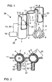
- FIG. 1 is a partly broken-away perspective view of a measuring device according to the invention attached to pressure pipes of a heating boiler;
- FIG. 2 is a cross-sectional view of the measuring device of the invention according to FIG. 1 ;
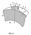
- FIG. 3 is an enlarged cross-sectional view of a portion of the measuring device of the invention according to FIG. 2 .
- FIG. 1 a perspective view of a measuring device 26 according to the invention in a heat exchanger 24 including three pressure pipes 1 , 1 ′, 1 ′′ (collectively referred to by reference numeral 1 ) which are respectively connected to one another at their side wall portions 10 by a connecting wall 11 .
- the pressure pipes 1 have a circumferential portion 7 , which is acted upon by a stream of heating fluid 8 and which has a center 9 .
- the pressure pipes have an indentation 4 at a first location 22 and an indentation 4 ′ at a second location 23 , in which one or more thermocouples or thermoelements 2 , 2 ′ and an electrical terminal 21 , 21 ′, (shown in FIG. 2 ) are inserted.
- An electrical terminal 27 (shown in FIG. 2 ) may also be placed at the connecting wall 11 , as an alternative or in addition to the electrical terminal 21 , 21 ′.
- the center 9 of the portion 7 is spatially separated from a center 5 of the indentation 4 .
- the one or more thermocouples 2 , 2 ′ and the electrical terminal 21 , 21 ′ are connected to a control device 16 through respective electrical lines 13 and connecting lines 25 .
- the control device 13 evaluates measurement data of the thermocouples 2 , 2 ′ and determines electrical resistance measured between the two locations 22 , 23 transversely to the pressure pipes 1 , 1 ′, displays corresponding operating states, in particular a degree of contamination and a degree of corrosion, and instigates appropriate maintenance or cleaning procedures.
- FIG. 2 is a cross-section of a measuring device according to the invention, showing the thermocouple 2 , 2 ′ disposed eccentrically or off-center in a portion 20 that is deformed by the indentation 4 .
- a pipe wall 3 is deformed by the indentation 4 in such a way that an inner chamber 18 exhibits a corresponding deformation.
- a reduction in the sectional area of the inner chamber 8 is about 20% as compared to a sectional area of an un-deformed pressure pipe 1 .
- the electrical lines 13 of the thermocouple 2 , 2 ′ extend in the indentation 4 inside a filling material 6 , as a result of which the lines are protected from mechanical, thermal and chemical influences.
- the electrical lines 13 are particularly protected on the side facing the stream of heating fluid 8 , i.e. at the circumferential portion.
- the electrical lines 13 normally extend in the filling material 6 beyond the wall 11 connecting the two pressure pipes 1 , 1 ′. Behind the connecting wall 11 , the electrical lines 13 are guided in a protective pipe 14 , which also protects the electrical lines.
- the protective pipe 14 is disposed at a side 15 of the pressure pipe 1 substantially opposite to the thermocouples 2 , 2 ′.
- the pressure pipes 1 , 1 ′ are electrically contacted by the electrical terminals 21 , 21 ′ which are electrically connected to the control device 16 through the connecting lines 25 , thus allowing measurement of the electrical resistance along and/or transversely to the pressure pipes 1 , 1 ′.
- Information regarding the state of the heat exchanger 24 in particular the pressure pipes thereof, for example information regarding its degree of corrosion, is obtained through the use of the electrical resistance.
- FIG. 3 is an enlarged cross-section of a measuring device of the invention according to FIG. 2 .
- the figure shows the two thermocouples 2 , 2 ′, which are disposed one above the other in the indentation 4 and are surrounded by an annular groove 12 .
- the annular groove 12 represents a heat conduction barrier which eliminates heat flux gradients obliquely to a heat flow 17 to be measured, thus improving the accuracy of the measuring device.
- the electrical lines 13 are guided in the filling material 6 , which fills the indentation 4 without protruding.
- the heat flow 17 is determined using the coefficients of thermal conduction.
- the invention relates to a measuring device 26 for a heat exchanger 24 having a pressure pipe 1 and at least one thermocouple 2 , 2 ′.
- the pressure pipe 1 has a pipe wall 3 , in which there is an indentation 4 , that extends over a portion 20 of the circumference of the pipe wall 3 .
- the indentation 4 receives the thermocouple 2 , 2 ′, is filled with filling material 6 , and is distinguished by allowing the thermocouple 2 , 2 ′ to be disposed eccentrically in the portion 20 that is deformed by the indentation 4 .
- the invention also relates to a method for producing measuring devices of this type.
- the invention is furthermore distinguished in that the eccentric configuration of the thermocouple 2 , 2 ′ allows the size of the indentation 4 to be reduced while the size of the thermocouple 2 , 2 ′ is kept constant. As a result thereof, the heat flux through the pipe wall 3 is impeded to a comparatively small degree and local overheating of the pipe wall 3 is prevented.
Abstract
Description
- This application is a continuing application, under 35 U.S.C. § 120, of copending International Application No. PCT/EP2003/011415, filed Oct. 15, 2003, which designated the United States; this application also claims the priority, under 35 U.S.C. § 119, of German Patent Application 102 48 312.4, filed Oct. 16, 2002; the prior applications are herewith incorporated by reference in their entirety.
- The present invention relates to a measuring device for pressure pipes of a heat exchanger or heating boiler including a pressure pipe and at least one thermocouple. The invention also relates to a method for producing a measuring device for pressure pipes, a method for monitoring an operating state of a heat exchanger having a pressure pipe, a heat exchanger, and a method for measuring a heat flux.
- When obtaining electrical energy by burning fossil fuels, for example, the thermal energy that is produced when the fuel is burnt is conventionally used to heat water flowing in pressure pipes. The heated water is used, for example, to produce steam and to drive a steam turbine.
- The efficiency of heating boilers of that type or of heat exchangers is determined, in particular, by the contamination of the outside and the inside of the pressure pipes. For example, combustion residues on the outside of the pipes cause the heating resistance of the pipes to increase and prevent a heat flux from the combustion chamber to the water. Increased heat resistance means that only a small portion of the heat from the water to be transferred may be received and converted into electrical energy.
- As described in UK
Patent Application GB 2 271 440 A, a determination may be made as to when cleaning of the pressure pipes is necessary by measuring the heat flux through the pipe wall. The conditions under which heat flux measurements on lines conveying high-pressure steam have to be carried out are especially problematic, in particular with regard to the high temperatures that are encountered. The high pressure also stresses the pressure pipes from the inside. - The heat flux (expressed in W/m2) is measured through the heat exchanger surface through the use of a heat flux sensor. That information can be used to study the behavior of the heating boiler or heat exchanger, to control a combustion chamber, to guide a water lance blower and to detect the contamination of heat exchanger surfaces.
- The general requirements for a heat flux sensor on pressure pipes are the stability, the strength and the reliability of the sensors under the respective conditions. Moreover, the sensors should influence the heat flux as little as possible, i.e. operation, size and dimensions thereof should influence the measured variable as little as possible. The sensors should also cause the pressure pipe surface to overheat as little as possible. They should impede the flow of the pressure medium as little as possible. For the sake of reliability, it is expedient to configure the sensors in such a way that they may be redundantly disposed.
- Known heat flux sensors for pressure pipes of a heating boiler are described in an article by Neal S. H. B. C., Northover E. W. et al., in Journal of Heat and Mass Transfer, Vol. 23, pp. 1023 to 1031, Pergament Press, 1980. In that case, two sensors are either applied to the surface of a pressure pipe or alternatively inserted into a thickened line. In the second variation, a sensor is embedded in a local concave portion of the pressure pipe. It is known that the second embodiment satisfies all of the requirements except for the fact that, as a result of the local concave portion, a flow resistance, which impedes the operation of the pressure pipes, is built up inside the pressure pipe.
- Thickened pressure pipe sensors are usually produced from a conventional pressure pipe in such a way that the pipe is provided with an indentation, in order to provide space for a sensor. The local indentation is filled with filling material, typically with welding material. The filling material is mechanically treated in such a way that a sensor may be embedded.
- A first, important aspect is that the pressure pipe wall temperature (and therefore the temperature of the sensor) is lower than the maximum permitted temperature for the pressure pipe and the sensor. This critical value is material-specific and may, for example, be about 600° C. Operating the system above 600° then rapidly impairs the efficiency of the pressure pipe and the sensor, so that the operation of the heating boiler is threatened by a malfunction of the pressure pipes. The pressure pipes exhibit, for example, wall thicknesses of between 4 mm and 10 mm and may advantageously be made of various molybdenum steel alloys. For example, at a steam temperature of 420° C. and a heat flux of approximately 250 kW/m2 and a 6 mm wall thickness, the outer wall temperature is about 450° C. If a heat flux sensor, which conventionally has an overall height of between 5 and 8 mm, is incorporated onto or into a pressure pipe of that type, the outside temperature of the pressure pipes, with the same heat flux and same steam temperature, remains, for example, at approximately 530° C., if typical material values are assumed. In the event of higher heat fluxes, higher steam temperatures or a cooling failure, the surface of the pressure pipe at the sensor easily reaches the critical temperature of 600° C. That shows that the thermal resistance of the heat flux sensor may not be ignored and therefore has to be reduced.
- In addition to the problem of overheating of the outer walls, the flow profile of the pressure medium inside the pressure pipes poses a further problem. A non-laminar flow of the pressure medium, for example a local vortex, may lead locally to a reduction of the heat transfer, and that may in turn cause local overheating. It is therefore conventional, as is known from UK
Patent Application GB 2 271 440 A, to keep the angle of inclination of the indentation as small as possible in the flow direction of the pressure medium, in order to prevent a release of flow. A further problem in conjunction with indentations is that, in particular at high pressures of the pressure medium, indentations of that type may lead to mechanical instabilities in the pressure pipes. - The definitive factor for reducing the size of the indentation is, on one hand, the sensitivity of the sensor and, on the other hand, the possibility of guiding the electrical lines of the sensor, from the sensor out of the combustion chamber.
- A further aim is to determine, in as comprehensive and precise a manner as possible, the parameters that are relevant to the operation of a heating boiler.
- It is accordingly an object of the invention to provide a heat flux measuring device for pressure pipes, a method for producing a measuring device, a method for monitoring an operating state of a heat exchanger, a heat exchanger, and a method for measuring a heat flux, which overcome the hereinafore-mentioned disadvantages of the heretofore-known devices and methods of this general type and which permit reliable measurement of the heat flux.
- With the foregoing and other objects in view there is provided, in accordance with the invention, a measuring device for a heat exchanger. The measuring device comprises a heat exchanger pressure pipe having a pipe wall with a circumference, and an indentation extending over and deforming a portion of the circumference. At least one thermocouple is disposed eccentrically in the portion of the circumference deformed by the indentation. Filling material fills the indentation.
- The pressure pipe is made of a mechanically highly stable and thermally stable material, in particular steel such as, for example, 15 Mo3. The pressure pipes are guided through the combustion chamber of the heating boiler, so that a heat exchange takes place between the inner chamber of the heating boiler and the pressure medium conveyed in the pressure pipes. The pressure medium may, for example, be water, which is converted into water vapor through the use of the heat absorption. The heat exchanger may be used for exchanging heat between two fluids, in particular between two gases. It may, in particular, also be a heating boiler for combustion, wherein the heat that is produced during combustion is dissipated by a cooling medium. The heat exchanger may also be used in a waste incineration plant.
- As a result of the eccentric configuration of the thermocouple in the portion that is deformed by the indentation, the indentation is used both for receiving the thermocouple and for guiding electrical lines of the thermocouple. This is particularly important if the electrical lines have to be protected from mechanical, thermal or chemical influences of the environment in a heating boiler such as, for example, combustion gases, which may occur as a result of both the thermocouple and the electrical lines being embedded into the filling material. The filling material thus protects both the thermocouple and the electrical lines. The filling material may, for example, be welding material.
- As a result of the eccentric configuration, the electrical lines of the thermocouple may be guided and protected over particularly long distances in the filling material.
- With the spatial requirements determined by the thermocouple and by the electrical lines, the eccentric configuration also allows the indentation to be used particularly efficiently. As a result thereof the indentation relative to the cross-section of the pressure pipe may be selected so as to be small in comparison with conventional constructions. Against the background of the flow behavior of the pressure medium in the pressure pipe, particularly small indentations are desirable in order to reduce the flow resistance in the pressure pipe.
- The eccentric configuration, and the reduced size of the indentation facilitated thereby, allows improved heat flux through the pipe wall. The size of the portion to be filled with filling material is reduced, as a result of which the heat resistance remains low as compared to conventional constructions. The reduced size of the indentation also generally reduces the curvature of the pipe wall, allowing greater strength of the pressure pipe to be attained, as is especially important, in particular, for high-pressure applications.
- As a result of the eccentric configuration, an increase in temperature in the region of the thermocouple is minimized. This improves the measurement accuracy of the thermocouple, on one hand, and the mechanical strength of the pressure pipe, on the other hand. The reduced size of the indentation prevents drops in pressure in the pressure medium along the pressure pipe, thus preventing local vortexes and partition regions. This ensures that no local overheating, resulting from the flow behavior of the pressure medium, occurs. The reduction in the internal cross-section of the pressure pipe in the eccentric configuration is less than 30%, advantageously less than 27%, particularly preferably less than 25%, corresponding to an improvement of about 20% over conventional constructions, which exhibit a reduction in internal cross-section of at least 38%. Pressure losses are also reduced by 20% as a result of the reduction in size of the indentation. However, the decrease in filling material also means that the production time of a measuring device of this type is shortened, since the production time is determined by the step of filling the indentation with filling material. The invention allows the amount of filling material required to be reduced by more than 20%, in particular more than 30%.
- In accordance with another feature of the invention, two thermocouples for measuring a heat flux are disposed eccentrically in a physically spaced or spatially separated manner in the indentation. Two temperatures, with which the gradient of the temperature profile may be determined in the first place, may be measured at various space points or locations using two thermocouples. Advantageously, the two thermocouples are disposed above each other in the indentation, so that the temperature gradient is detected through the pipe wall. In order to detect a temperature gradient along the pipe wall, it is expedient to space apart two thermocouples spatially, one behind the other, in the longitudinal direction of the pressure pipe. In order to detect the temperature profile in detail, it is expedient to use more than two thermocouples. Heat fluxes may be temporally detected with respect to their amount and/or their direction through the temperature profile and after calibration with respect to the coefficients of thermal conduction. This also allows temperatures to be measured at various points or locations.
- In accordance with a further feature of the invention, the pressure pipe includes a circumferential portion, which may be acted upon by a stream of heating fluid and the center of which is disposed with physical spacing or spatial separation from a center of the indentation. A stream of heating fluid is, for example, a stream of hot gas that is produced in the heating boiler during combustion such as, for example, a flame front. The circumferential portion faces and is acted upon by the stream of heating fluid. The center of the circumferential portion is usually exposed to a particular temperature stress. The indentation, which extends over a portion of the circumference of the pipe wall, includes the center that is located laterally to the center of the circumferential portion. This allows the electrical lines of a thermocouple, which is advantageously disposed in the proximity of the center, to be guided in the filling material of the indentation, so the electrical lines are mechanically, thermally and chemically protected over a particularly long distance.
- In accordance with an added feature of the invention, in order to measure a heat flux through the pipe wall, the thermocouples are disposed substantially above one another in the indentation in the pressure pipe. The pressure pipes may extend freely in the inner space of a heat exchanger, though they may also be connected to one another in a gas-tight manner at their lateral wall portions, thus forming an inner space of the heat exchanger, in which the stream of heating fluid may be enclosed and conveyed. The side wall portions may also be used to increase the size of the effectively active surface of the pressure pipes, so that improved heat transfer from the stream of heating fluid to the pressure medium takes place. The heat that is received by the side wall portions is passed onto and received from the pipe wall of the pressure pipe.
- In accordance with an additional feature of the invention, the thermocouples are surrounded by at least one heat conduction barrier. The heat conduction barrier provides thermal insulation, for preventing undesirable heat fluxes, which might, in particular, impair measurement. For example, for measuring the heat flux through the pipe wall, it is expedient to place an annular groove around the thermocouples, so that a drop in temperature along the pipe does not have any influence on the heat flux measurement through the pipe wall.
- As a result of the selection of different materials for the pressure pipe and the filling material, as well as for the thermocouples, local heat flux gradients, which limit the accuracy of measurement, may occur locally. An annular groove inhibits the heat flux gradients that do not extend parallel to the axis of the ring.
- In accordance with yet another feature of the invention, a protective pipe for electrical lines of the thermocouple is attached to the pressure pipe on a side of the pressure pipe substantially opposite to the thermocouple. The protective pipe protects the electrical lines of the thermocouple from mechanical, thermal or chemical influences. As a result of the configuration of the protective pipe on a side of the pressure pipe opposite to the thermocouple, the heat conduction of the protective pipe does not influence the measurement of the heat flux through the pipe wall. The electrical lines of the thermocouple are advantageously laid in the indentation.
- In accordance with yet a further feature of the invention, the filling material fills the indentation without protruding. This ensures that there is only a small contact surface for applied impurities, thus preventing a non-representative contamination of the outer wall of the pressure pipes. Moreover, a protrusion-free filling of the indentation also means that the hydrodynamic properties, in particular the flow resistance of the pressure pipe, are advantageous for the stream of heating fluid.
- With the objects of the invention in view, there is also provided a measuring device for a heat exchanger, comprising a pressure pipe and at least one thermocouple. The pressure pipe has a pipe wall, in which there is an indentation, that extends over a portion of the circumference of the pipe wall. The indentation receives the thermocouple and is filled with filling material. An electrical terminal is attached to the pressure pipe or to a connecting wall. Advantageously, the electrical terminal is attached in the indentation.
- In accordance with yet an added feature of the invention, a device for measuring a heat flux is also used to measure an electrical resistance along or transversely to components of the heat exchanger. For this purpose, an electrical terminal is integrated into the device for measuring a heat flux. The device for measuring a heat flux is connected to an electrical terminal in a compact, modular manner. The device for measuring the heat flux may be the measuring device according to the invention, but may also be a device known in the prior art.
- The degree of corrosion of the heat exchanger and, in particular, the extent of the corrosion of the pressure pipes or connecting walls that are exposed to the aggressive gases or liquids, may be inferred with the aid of the electrical resistance and the time variation thereof. The reduction in the wall thicknesses of the pressure pipes or connecting walls caused by corrosion results in an increase in electrical resistance along or transversely to the pressure pipes or connecting walls.
- The precise determination of the degree of corrosion is used for monitoring the heat exchanger during its operation. Material characteristic values such as the loss of material per period of operation (in units of nanometers per hour) or the wall thickness of the pressure pipes or connecting walls, are calculated. There are a plurality of methods for measuring erosion and corrosion. UK
Patent Application GB 2 262 608 A describes a local corrosion measurement sensor that contains a compensation device in order to reduce the influence of temperature fluctuations on the corrosion measurement. It is also known to undertake a four-point measurement along pressure pipes in order to determine the degree of corrosion not only locally, but also integrally over comparatively large distances. Since the resistance is highly temperature-dependent, additional temperature sensors, distributed over the heat exchanger, are required. The temperature-specific contribution is extracted from the integrally measured electrical resistance using additional temperature measurements, and the corrosion-specific content is determined. U.S. Patent Application Publication No. US 2003/055586A1 discloses a mathematical method, with which measurement errors in the electrical resistance measurement are minimized in a control model for electrical resistance mapping. Corrosion measurement devices of that type are, however, complex, since not only electrical contacts, but also additional temperatures sensors have to be attached to the pressure pipes. - In accordance with yet an additional feature of the invention, the heat flux sensors in the heat exchanger are used in a dual manner, namely for determining its degree of contamination and further material characteristic values such as, for example, its degree of corrosion. A particularly compact construction of the sensors is thereby attained, and an installation or retrofitting of an existing system is simplified. The number of additional temperature sensors that is required is reduced. The wiring of the sensors is also simplified. Moreover, it also allows information regarding the heat flux to be taken into account when determining the material characteristic values such as, for example, the degree of corrosion, as a result of which a higher degree of precision is attained when determining these characteristic values. The heat flux sensors allow the temperature profile in the heat exchanger to be determined with a great deal more accuracy, since the heat flux data may be taken into account as peripheral conditions in the thermal mapping. This allows the degree of corrosion to be determined from the temperature-dependent electrical resistance in a substantially more precise manner. It is also advantageous that the simultaneous measurement of both the electrical resistance and the heat flux causes metrological redundancy, so that if one sensor is omitted, the other sensors are able to adopt its function. In general, the invention has the advantage that the service life of the heat exchanger, in particular its pressure pipes, or the maintenance rates, may be predicted much more accurately.
- In accordance with again another feature of the invention, temperature fluctuations are used to identify the temperature-specific content of the electrical resistance. The integral electrical resistance, which is measured with time resolution, is accordingly correlated with the temperature fluctuation, which is measured with time resolution, and the temperature-specific content is extracted from the integrally measured electrical resistance.
- In accordance with again a further feature of the invention, the measuring device includes an electrical terminal on the pressure pipe and/or the connecting walls.
- With the objects of the invention in view, there is also provided a method for producing a measuring device in a pressure pipe of a heat exchanger. The method comprises providing an indentation extending over and deforming a portion of a circumference of a pipe wall of the pressure pipe. At least one thermocouple is placed eccentrically in the portion deformed by the indentation. The indentation is substantially filled with filling material.
- As a result of the eccentric configuration of the thermocouple in the indentation, the size of the indentation is reduced, as a result of which the amount of filling material required for filling the indentation is reduced. The reduction in the amount of filling material to be filled leads to a shortening of the production time.
- In accordance with another mode of the invention, at least two thermocouples are disposed eccentrically in a physically spaced or spatially separated manner in the indentation. It is advantageous to fill the indentation with filling material without protrusion.
- In accordance with a further mode of the invention, the pressure pipe or a connecting wall is provided with an electrical terminal. This allows a dual use of the measuring device in a simple manner, namely for measuring a heat flux and for measuring an electrical resistance, as a result of which information regarding both the degree of contamination and material characteristic values, such as, for example, the state of corrosion or erosion of the heat exchanger including a modular unit, is obtained in a precise manner.
- With the objects of the invention in view, there is additionally provided a method for monitoring an operating state of a heat exchanger having a pressure pipe. The method comprises measuring an electrical resistance between a first location and a second location of the heat exchanger. A heat flux is detected at least at one of the first and second locations.
- In accordance with another mode of the invention, the locations are disposed at a distance along and/or transversely to the pressure pipes. The simultaneous use of one location both for measuring the heat flux and for measuring the degree of corrosion reduces costs in the installation and maintenance of the monitoring system. The temperatures and temperature gradients measured locally by the measuring device at one location are advantageously used to interpolate the temperature profile or temperature gradient profile between the measurement locations, and thus to estimate the temperature-dependent content of the electrical resistance, as a result of which the degree of corrosion may be determined with substantially higher accuracy.
- With the objects of the invention in view, there is furthermore provided a heat exchanger, comprising a measuring device according to the invention.
- In operation, the heat exchanger is impeded to a comparatively small degree by the measuring device for measuring the heat flux through the pipe wall, and local overheating of the pipe wall is avoided. Moreover, information regarding the degree of corrosion or erosion may optionally also be obtained economically in this manner.
- With the objects of the invention in view, there is concomitantly provided a method for measuring a heat flux. The method comprises using a measuring device, for example of the invention, for establishing an electrical resistance for determining a degree of corrosion of the heat exchanger.
- The measuring device is thus used in a dual manner as described. This advantageous dual use is possible not only in conjunction with the measuring device according to the invention, but also in conjunction with measuring devices as known from the prior art.
- Other features which are considered as characteristic for the invention are set forth in the appended claims.
- Although the invention is illustrated and described herein as embodied in a heat flux measuring device for pressure pipes, a method for producing a measuring device, a method for monitoring an operating state of a heat exchanger, a heat exchanger and a method for measuring a heat flux, it is nevertheless not intended to be limited to the details shown, since various modifications and structural changes may be made therein without departing from the spirit of the invention and within the scope and range of equivalents of the claims.
- The construction and method of operation of the invention, however, together with additional objects and advantages thereof will be best understood from the following description of specific embodiments when read in connection with the accompanying drawings.
-
FIG. 1 is a partly broken-away perspective view of a measuring device according to the invention attached to pressure pipes of a heating boiler; -
FIG. 2 is a cross-sectional view of the measuring device of the invention according toFIG. 1 ; and -
FIG. 3 is an enlarged cross-sectional view of a portion of the measuring device of the invention according toFIG. 2 . - Referring now to the figures of the drawings in detail and first, particularly, to
FIG. 1 thereof, there is seen a perspective view of a measuringdevice 26 according to the invention in aheat exchanger 24 including threepressure pipes side wall portions 10 by a connectingwall 11. Thepressure pipes 1 have a circumferential portion 7, which is acted upon by a stream ofheating fluid 8 and which has acenter 9. According to the invention, the pressure pipes have anindentation 4 at afirst location 22 and anindentation 4′ at asecond location 23, in which one or more thermocouples orthermoelements electrical terminal FIG. 2 ) are inserted. An electrical terminal 27 (shown inFIG. 2 ) may also be placed at the connectingwall 11, as an alternative or in addition to theelectrical terminal center 9 of the portion 7 is spatially separated from acenter 5 of theindentation 4. The one ormore thermocouples electrical terminal control device 16 through respectiveelectrical lines 13 and connectinglines 25. Thecontrol device 13 evaluates measurement data of thethermocouples locations pressure pipes -
FIG. 2 is a cross-section of a measuring device according to the invention, showing thethermocouple portion 20 that is deformed by theindentation 4. Apipe wall 3 is deformed by theindentation 4 in such a way that aninner chamber 18 exhibits a corresponding deformation. A reduction in the sectional area of theinner chamber 8 is about 20% as compared to a sectional area of anun-deformed pressure pipe 1. Theelectrical lines 13 of thethermocouple indentation 4 inside a fillingmaterial 6, as a result of which the lines are protected from mechanical, thermal and chemical influences. Theelectrical lines 13 are particularly protected on the side facing the stream ofheating fluid 8, i.e. at the circumferential portion. Theelectrical lines 13 normally extend in the fillingmaterial 6 beyond thewall 11 connecting the twopressure pipes wall 11, theelectrical lines 13 are guided in aprotective pipe 14, which also protects the electrical lines. Theprotective pipe 14 is disposed at aside 15 of thepressure pipe 1 substantially opposite to thethermocouples pressure pipes electrical terminals control device 16 through the connectinglines 25, thus allowing measurement of the electrical resistance along and/or transversely to thepressure pipes heat exchanger 24, in particular the pressure pipes thereof, for example information regarding its degree of corrosion, is obtained through the use of the electrical resistance. -
FIG. 3 is an enlarged cross-section of a measuring device of the invention according toFIG. 2 . The figure shows the twothermocouples indentation 4 and are surrounded by anannular groove 12. Theannular groove 12 represents a heat conduction barrier which eliminates heat flux gradients obliquely to aheat flow 17 to be measured, thus improving the accuracy of the measuring device. Theelectrical lines 13 are guided in the fillingmaterial 6, which fills theindentation 4 without protruding. As a result of the spatial separation of the twothermocouples heat flow 17 is determined using the coefficients of thermal conduction. - The invention relates to a measuring
device 26 for aheat exchanger 24 having apressure pipe 1 and at least onethermocouple pressure pipe 1 has apipe wall 3, in which there is anindentation 4, that extends over aportion 20 of the circumference of thepipe wall 3. Theindentation 4 receives thethermocouple material 6, and is distinguished by allowing thethermocouple portion 20 that is deformed by theindentation 4. The invention also relates to a method for producing measuring devices of this type. - The invention is furthermore distinguished in that the eccentric configuration of the
thermocouple indentation 4 to be reduced while the size of thethermocouple pipe wall 3 is impeded to a comparatively small degree and local overheating of thepipe wall 3 is prevented.
Claims (21)
Priority Applications (1)
| Application Number | Priority Date | Filing Date | Title |
|---|---|---|---|
| US11/108,438 US7249885B2 (en) | 2002-10-16 | 2005-04-18 | Heat flux measuring device for pressure pipes, method for producing a measuring device, method for monitoring an operating state of a heat exchanger, heat exchanger and method for measuring a heat flux |
Applications Claiming Priority (4)
| Application Number | Priority Date | Filing Date | Title |
|---|---|---|---|
| DE10248312A DE10248312A1 (en) | 2002-10-16 | 2002-10-16 | Heat flow measuring device for pressure pipe and method for measuring heat flow through pressure pipes |
| DE10248312.4 | 2002-10-16 | ||
| PCT/EP2003/011415 WO2004036116A2 (en) | 2002-10-16 | 2003-10-15 | Heat flow measuring device for pressure pipes and method for measuring a heat flow penetrating pressure pipes |
| US11/108,438 US7249885B2 (en) | 2002-10-16 | 2005-04-18 | Heat flux measuring device for pressure pipes, method for producing a measuring device, method for monitoring an operating state of a heat exchanger, heat exchanger and method for measuring a heat flux |
Related Parent Applications (1)
| Application Number | Title | Priority Date | Filing Date |
|---|---|---|---|
| PCT/EP2003/011415 Continuation WO2004036116A2 (en) | 2002-10-16 | 2003-10-15 | Heat flow measuring device for pressure pipes and method for measuring a heat flow penetrating pressure pipes |
Publications (2)
| Publication Number | Publication Date |
|---|---|
| US20050217841A1 true US20050217841A1 (en) | 2005-10-06 |
| US7249885B2 US7249885B2 (en) | 2007-07-31 |
Family
ID=35053009
Family Applications (1)
| Application Number | Title | Priority Date | Filing Date |
|---|---|---|---|
| US11/108,438 Expired - Lifetime US7249885B2 (en) | 2002-10-16 | 2005-04-18 | Heat flux measuring device for pressure pipes, method for producing a measuring device, method for monitoring an operating state of a heat exchanger, heat exchanger and method for measuring a heat flux |
Country Status (1)
| Country | Link |
|---|---|
| US (1) | US7249885B2 (en) |
Cited By (11)
| Publication number | Priority date | Publication date | Assignee | Title |
|---|---|---|---|---|
| US20070144726A1 (en) * | 2003-12-30 | 2007-06-28 | Thomas Scherer | Method for controlling the temperature of feed air injected into the cabin zone of a passenger aircraft |
| US20090262777A1 (en) * | 2008-04-18 | 2009-10-22 | General Electric Company | Heat flux measurement device for estimating fouling thickness |
| JP2013213640A (en) * | 2012-04-03 | 2013-10-17 | Samson Co Ltd | Boiler |
| US20150098486A1 (en) * | 2013-10-08 | 2015-04-09 | Halliburton Energy Services, Inc. | Assembly for Measuring Temperature of Materials Flowing Through Tubing in a Well System |
| JP2017072578A (en) * | 2015-10-05 | 2017-04-13 | 株式会社デンソー | Monitoring device and abnormality diagnostic device |
| US20170212065A1 (en) * | 2016-01-25 | 2017-07-27 | Rosemount Inc. | Non-intrusive process fluid temperature calculation system |
| EP3428593A1 (en) * | 2017-07-10 | 2019-01-16 | Linde Aktiengesellschaft | Fluid conduit component and method for its production |
| FR3069321A1 (en) * | 2017-07-24 | 2019-01-25 | Commissariat A L'energie Atomique Et Aux Energies Alternatives | SYSTEM AND METHOD FOR EVALUATING AT LEAST ONE OPERATING CONDITION OF A HEAT EXCHANGER |
| US11226242B2 (en) | 2016-01-25 | 2022-01-18 | Rosemount Inc. | Process transmitter isolation compensation |
| US11226255B2 (en) | 2016-09-29 | 2022-01-18 | Rosemount Inc. | Process transmitter isolation unit compensation |
| US20220187065A1 (en) * | 2020-12-15 | 2022-06-16 | A. O. Smith (China) Water Heater Co., Ltd. | Water heater, and scale detection system and method |
Families Citing this family (12)
| Publication number | Priority date | Publication date | Assignee | Title |
|---|---|---|---|---|
| WO2006105368A2 (en) * | 2005-03-31 | 2006-10-05 | Ashland Licensing And Intellectual Property Llc | Apparatuses and systems for monitoring fouling of aqueous systems including enhanced heat exchanger tubes |
| GB0508584D0 (en) * | 2005-04-28 | 2005-06-01 | Boiler Man Systems Internation | A pipe assembly |
| DE102006031343A1 (en) * | 2006-07-06 | 2008-01-10 | Epcos Ag | Temperature measuring device |
| DE102008044253A1 (en) * | 2008-12-02 | 2010-06-10 | BSH Bosch und Siemens Hausgeräte GmbH | Evaporator for a refrigeration device |
| DE102009009592A1 (en) * | 2009-02-19 | 2010-08-26 | Clyde Bergemann Gmbh Maschinen- Und Apparatebau | Measuring device for a heat exchanger |
| US9196387B2 (en) * | 2011-11-03 | 2015-11-24 | Atomic Energy Of Canada Limited | Apparatus and method for detecting position of annulus spacer between concentric tubes |
| CN103185643B (en) * | 2011-12-29 | 2015-07-15 | 珠海格力电器股份有限公司 | Thermo-bulb fixing device and fixing structure adopting fixing device |
| BE1022051B1 (en) * | 2013-05-23 | 2016-02-10 | Sa Cockerill Maintenance & Ingenierie | THERMAL FLOW SENSOR |
| US9360377B2 (en) * | 2013-12-26 | 2016-06-07 | Rosemount Inc. | Non-intrusive temperature measurement assembly |
| CA3003130C (en) * | 2015-10-23 | 2023-01-24 | Atomic Energy Of Canada Limited / Energie Atomique Du Canada Limitee | Test apparatus and instrumented conduit for use with same |
| US11067520B2 (en) | 2016-06-29 | 2021-07-20 | Rosemount Inc. | Process fluid temperature measurement system with improved process intrusion |
| RU2770168C1 (en) | 2018-09-28 | 2022-04-14 | Роузмаунт Инк. | Non-invasive indication of the temperature of the process medium with reduced error |
Citations (35)
| Publication number | Priority date | Publication date | Assignee | Title |
|---|---|---|---|---|
| US3204458A (en) * | 1962-07-02 | 1965-09-07 | Gulton Ind Inc | Ultrasonic flowmeter |
| US4023411A (en) * | 1975-11-05 | 1977-05-17 | Hans Escher | Temperature measuring device |
| US4203186A (en) * | 1975-02-07 | 1980-05-20 | Exxon Research & Engineering Co. | Heat transfer |
| US4346864A (en) * | 1980-11-21 | 1982-08-31 | Wilgood Corporation | Means and method for mounting temperature sensors |
| US4488516A (en) * | 1983-11-18 | 1984-12-18 | Combustion Engineering, Inc. | Soot blower system |
| US4527908A (en) * | 1983-07-07 | 1985-07-09 | Cise - Centro Informazioni Studi Esperienze S.P.A. | Instrument unit for measuring temperatures and heat flux in evaporative walls of steam generators |
| US4595287A (en) * | 1984-01-18 | 1986-06-17 | The United States Of America As Represented By The Secretary Of The Army | Doppler effect laser velocity measuring system |
| US4595297A (en) * | 1985-10-15 | 1986-06-17 | Shell Oil Company | Method and apparatus for measure of heat flux through a heat exchange tube |
| US4603660A (en) * | 1984-02-24 | 1986-08-05 | University Of Waterloo | Convection section ash monitoring |
| US4628870A (en) * | 1984-07-31 | 1986-12-16 | Westinghouse Electric Corp. | Model steam generator having means to facilitate inspection of sample tubes |
| US4671675A (en) * | 1983-07-07 | 1987-06-09 | Cise-Centro Informazioni Studi Esperienzes | Tubular element instrumented with temperature sensors, in particular for measuring overtemperatures in the tubes of thermoelectric power plant superheaters |
| US4722610A (en) * | 1986-03-07 | 1988-02-02 | Technology For Energy Corporation | Monitor for deposition on heat transfer surfaces |
| US4856911A (en) * | 1984-06-05 | 1989-08-15 | Bertin & Cie | Method and devices for measuring the temperature of a running filiform element |
| US4868151A (en) * | 1986-06-25 | 1989-09-19 | Jujo Paper Co., Ltd. | Heat-sensitive recording material |
| US5050108A (en) * | 1989-11-30 | 1991-09-17 | Aptech Engineering, Inc. | Method for extending the useful life of boiler tubes |
| US5052190A (en) * | 1988-08-04 | 1991-10-01 | Super S.E.E.R. Systems Inc. | Apparatus for the sensing of refrigerant temperatures and the control of refrigerant loading |
| US5064604A (en) * | 1990-02-07 | 1991-11-12 | Westinghouse Electric Corp. | Cost effective fluid line status sensor system |
| US5141335A (en) * | 1991-03-15 | 1992-08-25 | Alltemp Sensors Inc. | Thermocouple connector |
| US5157619A (en) * | 1988-10-31 | 1992-10-20 | Westinghouse Electric Corp. | Abnormal thermal loading effects monitoring system |
| US5172979A (en) * | 1991-11-29 | 1992-12-22 | Texaco Inc. | Heater tube skin thermocouple |
| US5382093A (en) * | 1993-02-22 | 1995-01-17 | Gay Engineering & Sales Co., Inc. | Removable temperature measuring device |
| US5450765A (en) * | 1994-03-01 | 1995-09-19 | Tdw Delaware, Inc. | Apparatus for providing signal communication between the interior and exterior of a pipeline |
| US5691466A (en) * | 1995-06-28 | 1997-11-25 | J.T.L. Systems Ltd. | Liquid-sensing apparatus and method |
| US5711608A (en) * | 1993-10-12 | 1998-01-27 | Finney; Philip F. | Thermocouple assemblies |
| US5711607A (en) * | 1995-12-04 | 1998-01-27 | Argonaut Technologies, Inc. | Temperature measurement technique with automatic verification of contact between probe and object |
| US6112580A (en) * | 1996-02-10 | 2000-09-05 | Michael Hesky Gmbh | Device for detecting leaks in pipelines |
| US6217211B1 (en) * | 1998-01-27 | 2001-04-17 | Michael Hesky Gmbh | Temperature measuring and monitoring |
| US6248077B1 (en) * | 1982-07-19 | 2001-06-19 | Edwards Lifesciences Corp. | System for sensing a characteristic of fluid flowing to or from a body |
| US6485174B1 (en) * | 2000-10-27 | 2002-11-26 | The Babcock & Wilcox Company | Attachable heat flux measuring device |
| US20030055586A1 (en) * | 2001-08-21 | 2003-03-20 | Alstom Power N.V. | Regularization model for electrical resistance mapping |
| US20030079867A1 (en) * | 2001-06-08 | 2003-05-01 | Min Chang | Increased heat exchange in two or three phase slurry |
| US6579006B1 (en) * | 2000-08-25 | 2003-06-17 | Blake Pariseau | Thermochromic method and device for use relative to a product container |
| US20040151230A1 (en) * | 2003-02-03 | 2004-08-05 | Das Sathish R. | Sensor bulb attachment |
| US6848373B2 (en) * | 2003-02-21 | 2005-02-01 | Breen Energy Solutions | Method of monitoring heat flux and controlling corrosion of furnace wall tubes |
| US6942384B2 (en) * | 2000-05-19 | 2005-09-13 | De Dietrich Process Systems | Housing for probe used to measure temperature through a container wall |
Family Cites Families (2)
| Publication number | Priority date | Publication date | Assignee | Title |
|---|---|---|---|---|
| GB9126881D0 (en) | 1991-12-18 | 1992-02-19 | Rowan Technologies | Transducer for corrosion or erosion measurement |
| GB9220856D0 (en) | 1992-10-03 | 1992-11-18 | Boiler Management Systems Limi | Improvements in or relating to boiler wall cleaning |
-
2005
- 2005-04-18 US US11/108,438 patent/US7249885B2/en not_active Expired - Lifetime
Patent Citations (35)
| Publication number | Priority date | Publication date | Assignee | Title |
|---|---|---|---|---|
| US3204458A (en) * | 1962-07-02 | 1965-09-07 | Gulton Ind Inc | Ultrasonic flowmeter |
| US4203186A (en) * | 1975-02-07 | 1980-05-20 | Exxon Research & Engineering Co. | Heat transfer |
| US4023411A (en) * | 1975-11-05 | 1977-05-17 | Hans Escher | Temperature measuring device |
| US4346864A (en) * | 1980-11-21 | 1982-08-31 | Wilgood Corporation | Means and method for mounting temperature sensors |
| US6248077B1 (en) * | 1982-07-19 | 2001-06-19 | Edwards Lifesciences Corp. | System for sensing a characteristic of fluid flowing to or from a body |
| US4671675A (en) * | 1983-07-07 | 1987-06-09 | Cise-Centro Informazioni Studi Esperienzes | Tubular element instrumented with temperature sensors, in particular for measuring overtemperatures in the tubes of thermoelectric power plant superheaters |
| US4527908A (en) * | 1983-07-07 | 1985-07-09 | Cise - Centro Informazioni Studi Esperienze S.P.A. | Instrument unit for measuring temperatures and heat flux in evaporative walls of steam generators |
| US4488516A (en) * | 1983-11-18 | 1984-12-18 | Combustion Engineering, Inc. | Soot blower system |
| US4595287A (en) * | 1984-01-18 | 1986-06-17 | The United States Of America As Represented By The Secretary Of The Army | Doppler effect laser velocity measuring system |
| US4603660A (en) * | 1984-02-24 | 1986-08-05 | University Of Waterloo | Convection section ash monitoring |
| US4856911A (en) * | 1984-06-05 | 1989-08-15 | Bertin & Cie | Method and devices for measuring the temperature of a running filiform element |
| US4628870A (en) * | 1984-07-31 | 1986-12-16 | Westinghouse Electric Corp. | Model steam generator having means to facilitate inspection of sample tubes |
| US4595297A (en) * | 1985-10-15 | 1986-06-17 | Shell Oil Company | Method and apparatus for measure of heat flux through a heat exchange tube |
| US4722610A (en) * | 1986-03-07 | 1988-02-02 | Technology For Energy Corporation | Monitor for deposition on heat transfer surfaces |
| US4868151A (en) * | 1986-06-25 | 1989-09-19 | Jujo Paper Co., Ltd. | Heat-sensitive recording material |
| US5052190A (en) * | 1988-08-04 | 1991-10-01 | Super S.E.E.R. Systems Inc. | Apparatus for the sensing of refrigerant temperatures and the control of refrigerant loading |
| US5157619A (en) * | 1988-10-31 | 1992-10-20 | Westinghouse Electric Corp. | Abnormal thermal loading effects monitoring system |
| US5050108A (en) * | 1989-11-30 | 1991-09-17 | Aptech Engineering, Inc. | Method for extending the useful life of boiler tubes |
| US5064604A (en) * | 1990-02-07 | 1991-11-12 | Westinghouse Electric Corp. | Cost effective fluid line status sensor system |
| US5141335A (en) * | 1991-03-15 | 1992-08-25 | Alltemp Sensors Inc. | Thermocouple connector |
| US5172979A (en) * | 1991-11-29 | 1992-12-22 | Texaco Inc. | Heater tube skin thermocouple |
| US5382093A (en) * | 1993-02-22 | 1995-01-17 | Gay Engineering & Sales Co., Inc. | Removable temperature measuring device |
| US5711608A (en) * | 1993-10-12 | 1998-01-27 | Finney; Philip F. | Thermocouple assemblies |
| US5450765A (en) * | 1994-03-01 | 1995-09-19 | Tdw Delaware, Inc. | Apparatus for providing signal communication between the interior and exterior of a pipeline |
| US5691466A (en) * | 1995-06-28 | 1997-11-25 | J.T.L. Systems Ltd. | Liquid-sensing apparatus and method |
| US5711607A (en) * | 1995-12-04 | 1998-01-27 | Argonaut Technologies, Inc. | Temperature measurement technique with automatic verification of contact between probe and object |
| US6112580A (en) * | 1996-02-10 | 2000-09-05 | Michael Hesky Gmbh | Device for detecting leaks in pipelines |
| US6217211B1 (en) * | 1998-01-27 | 2001-04-17 | Michael Hesky Gmbh | Temperature measuring and monitoring |
| US6942384B2 (en) * | 2000-05-19 | 2005-09-13 | De Dietrich Process Systems | Housing for probe used to measure temperature through a container wall |
| US6579006B1 (en) * | 2000-08-25 | 2003-06-17 | Blake Pariseau | Thermochromic method and device for use relative to a product container |
| US6485174B1 (en) * | 2000-10-27 | 2002-11-26 | The Babcock & Wilcox Company | Attachable heat flux measuring device |
| US20030079867A1 (en) * | 2001-06-08 | 2003-05-01 | Min Chang | Increased heat exchange in two or three phase slurry |
| US20030055586A1 (en) * | 2001-08-21 | 2003-03-20 | Alstom Power N.V. | Regularization model for electrical resistance mapping |
| US20040151230A1 (en) * | 2003-02-03 | 2004-08-05 | Das Sathish R. | Sensor bulb attachment |
| US6848373B2 (en) * | 2003-02-21 | 2005-02-01 | Breen Energy Solutions | Method of monitoring heat flux and controlling corrosion of furnace wall tubes |
Cited By (18)
| Publication number | Priority date | Publication date | Assignee | Title |
|---|---|---|---|---|
| US20070144726A1 (en) * | 2003-12-30 | 2007-06-28 | Thomas Scherer | Method for controlling the temperature of feed air injected into the cabin zone of a passenger aircraft |
| US7775447B2 (en) * | 2003-12-30 | 2010-08-17 | Airbus Deutschland Gmbh | Method for controlling the temperature of feed air injected into the cabin zone of a passenger aircraft |
| US20090262777A1 (en) * | 2008-04-18 | 2009-10-22 | General Electric Company | Heat flux measurement device for estimating fouling thickness |
| US8147130B2 (en) * | 2008-04-18 | 2012-04-03 | General Electric Company | Heat flux measurement device for estimating fouling thickness |
| JP2013213640A (en) * | 2012-04-03 | 2013-10-17 | Samson Co Ltd | Boiler |
| US9976409B2 (en) * | 2013-10-08 | 2018-05-22 | Halliburton Energy Services, Inc. | Assembly for measuring temperature of materials flowing through tubing in a well system |
| US20150098486A1 (en) * | 2013-10-08 | 2015-04-09 | Halliburton Energy Services, Inc. | Assembly for Measuring Temperature of Materials Flowing Through Tubing in a Well System |
| JP2017072578A (en) * | 2015-10-05 | 2017-04-13 | 株式会社デンソー | Monitoring device and abnormality diagnostic device |
| US20170212065A1 (en) * | 2016-01-25 | 2017-07-27 | Rosemount Inc. | Non-intrusive process fluid temperature calculation system |
| US10670546B2 (en) * | 2016-01-25 | 2020-06-02 | Rosemount Inc. | Non-intrusive process fluid temperature calculation system |
| US11226242B2 (en) | 2016-01-25 | 2022-01-18 | Rosemount Inc. | Process transmitter isolation compensation |
| US11630072B2 (en) | 2016-01-25 | 2023-04-18 | Rosemount Inc. | Non-intrusive process fluid temperature calculation system |
| US11226255B2 (en) | 2016-09-29 | 2022-01-18 | Rosemount Inc. | Process transmitter isolation unit compensation |
| EP3428593A1 (en) * | 2017-07-10 | 2019-01-16 | Linde Aktiengesellschaft | Fluid conduit component and method for its production |
| FR3069321A1 (en) * | 2017-07-24 | 2019-01-25 | Commissariat A L'energie Atomique Et Aux Energies Alternatives | SYSTEM AND METHOD FOR EVALUATING AT LEAST ONE OPERATING CONDITION OF A HEAT EXCHANGER |
| EP3435067A1 (en) * | 2017-07-24 | 2019-01-30 | Commissariat à l'Energie Atomique et aux Energies Alternatives | System and method for evaluating at least one operating condition of a heat exchanger |
| US20220187065A1 (en) * | 2020-12-15 | 2022-06-16 | A. O. Smith (China) Water Heater Co., Ltd. | Water heater, and scale detection system and method |
| US11920923B2 (en) * | 2020-12-15 | 2024-03-05 | A. O. Smith Corporation | Water heater, and scale detection system and method |
Also Published As
| Publication number | Publication date |
|---|---|
| US7249885B2 (en) | 2007-07-31 |
Similar Documents
| Publication | Publication Date | Title |
|---|---|---|
| US7249885B2 (en) | Heat flux measuring device for pressure pipes, method for producing a measuring device, method for monitoring an operating state of a heat exchanger, heat exchanger and method for measuring a heat flux | |
| US8591102B2 (en) | Measuring device for a heat exchanger | |
| US6485174B1 (en) | Attachable heat flux measuring device | |
| KR101859309B1 (en) | Heat transfer tube life estimating system | |
| JP4466232B2 (en) | Boiler deterioration diagnosis method, apparatus, system, and recording medium recording program | |
| US10401206B2 (en) | Thermal, flow measuring device | |
| GB2410558A (en) | Heat flow measuring device for pressure pipes and method for measuring a heat flow penetrating pressure pipes | |
| JP5215750B2 (en) | Sensor, liquid film measuring device | |
| KR20080033268A (en) | Boiler system and method of controlling a boiler system | |
| EP3779320B1 (en) | Leakage detection in condensing water heater | |
| GB2271440A (en) | Optimising boiler cleaning | |
| AU2014270734B2 (en) | Heat flow sensor | |
| KR20210038572A (en) | Temperature sensor system | |
| JP6799199B1 (en) | Boiler tubing, boiler tubing unit, and furnace | |
| JP2002221303A (en) | Method of measuring furnace interior side temperature of membrane panel | |
| KR102006828B1 (en) | Erosion and high-temperature corrosion monitoring apparatus using the bimetal | |
| JP3892629B2 (en) | Overheat damage diagnosis method for boiler water wall pipe | |
| JPS6321129B2 (en) | ||
| JPH1123373A (en) | Fluid thermometer | |
| KR20080081140A (en) | A thermocouple for a flowing bed boiler | |
| JP4594887B2 (en) | Lined damage detection method and corrosive fluid container | |
| JPH11201406A (en) | Device for judging adhesion of substance for dropping heat conductivity of boiler | |
| JP5374344B2 (en) | Marine boiler structure | |
| JP7000166B2 (en) | Heat exchanger leak detection method | |
| JP2001183213A (en) | Level gauge and level alarm |
Legal Events
| Date | Code | Title | Description |
|---|---|---|---|
| AS | Assignment |
Owner name: CLYDE BERGEMANN GMBH, GERMANY Free format text: ASSIGNMENT OF ASSIGNORS INTEREST;ASSIGNORS:DEN ENDE, JOHANNES VAN;DEN BOS, CORNELIS JAN VAN;FRACH, MANFRED;AND OTHERS;REEL/FRAME:019334/0587;SIGNING DATES FROM 20050607 TO 20050613 |
|
| STCF | Information on status: patent grant |
Free format text: PATENTED CASE |
|
| FPAY | Fee payment |
Year of fee payment: 4 |
|
| FPAY | Fee payment |
Year of fee payment: 8 |
|
| MAFP | Maintenance fee payment |
Free format text: PAYMENT OF MAINTENANCE FEE, 12TH YEAR, LARGE ENTITY (ORIGINAL EVENT CODE: M1553); ENTITY STATUS OF PATENT OWNER: LARGE ENTITY Year of fee payment: 12 |