US20060146292A1 - Display projection apparatus - Google Patents
Display projection apparatus Download PDFInfo
- Publication number
- US20060146292A1 US20060146292A1 US11/029,622 US2962205A US2006146292A1 US 20060146292 A1 US20060146292 A1 US 20060146292A1 US 2962205 A US2962205 A US 2962205A US 2006146292 A1 US2006146292 A1 US 2006146292A1
- Authority
- US
- United States
- Prior art keywords
- optical beam
- beam path
- optical
- path
- light
- Prior art date
- Legal status (The legal status is an assumption and is not a legal conclusion. Google has not performed a legal analysis and makes no representation as to the accuracy of the status listed.)
- Granted
Links
Images

Classifications
-
- G—PHYSICS
- G03—PHOTOGRAPHY; CINEMATOGRAPHY; ANALOGOUS TECHNIQUES USING WAVES OTHER THAN OPTICAL WAVES; ELECTROGRAPHY; HOLOGRAPHY
- G03B—APPARATUS OR ARRANGEMENTS FOR TAKING PHOTOGRAPHS OR FOR PROJECTING OR VIEWING THEM; APPARATUS OR ARRANGEMENTS EMPLOYING ANALOGOUS TECHNIQUES USING WAVES OTHER THAN OPTICAL WAVES; ACCESSORIES THEREFOR
- G03B21/00—Projectors or projection-type viewers; Accessories therefor
- G03B21/005—Projectors using an electronic spatial light modulator but not peculiar thereto
- G03B21/008—Projectors using an electronic spatial light modulator but not peculiar thereto using micromirror devices
Definitions
- the invention relates in general to image projection, and more particularly to a projection display apparatus
- a conventional projection system includes a light source, a digital micro-mirror device (DMD), such as one developed by Texas Instruments, and a set of projection lenses.
- the light source produces a light beam, which is imaged onto the DMD through a set of relay optics.
- the DMD modulates the light beam and in turn images the modulated light beam, through the projection lenses, onto a display screen to display an image.
- a color wheel is often used in addition to spatially filter the light beam from the lamp into respective red, green and blue components.
- the invention achieves the above-identified object by providing a projection display apparatus.
- the apparatus includes an illumination system, a light integrator, a first mirror module, a second mirror module, a beam condensing module, a total internal reflection (TIR) prism, a light modulator, and a set of projection lenses.
- the illumination system generates an optical beam propagating along a first beam path in a first direction.
- the light integrator disposed on the first beam path, is for homogenizing the optical beam.
- the first mirror module is for directing the optical beam from the light integrator to a second direction, such that the optical beam propagates along a second beam path.
- the second mirror module is for directing the optical beam from the first mirror module to a third direction, such that the optical beam propagates along a third beam path.
- the beam condensing module includes at least a condenser, which is disposed on at least one of the first beam path, the second beam path, and the third beam path, for converging the optical beam.
- the total internal reflection (TIR) prism includes a prism surface and is for receiving the optical beam from the second mirror module.
- the light modulator includes a panel, and receives the optical beam from the prism surface to illuminate the panel thereof, and selectively reflects the optical beam, such that the reflected optical beam propagates along a fourth beam path in a fourth direction.
- the projection lenses are for receiving and projecting the optical beam, which is reflected from the light modulator, onto a display screen to display an image.
- the first beam path and the fourth beam path are substantially perpendicular with respect to each other.
- FIG. 1 shows a block diagram of a projection display apparatus according to a preferred embodiment of the invention.
- FIG. 2 shows a top view of one example of the projection display apparatus of FIG. 1 on a X-(-Z) plane
- FIG. 3 shows a side view of the projection display apparatus 300 of FIG. 2 in on a X-Y plane.
- FIG. 4 shows a projection display apparatus according to a embodiment of the invention realized with a dual lamp system.
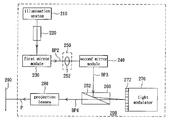
- FIG. 1 shows a block diagram of a projection display apparatus according to a preferred embodiment of the invention.
- the projection display apparatus includes an illumination system 210 , a light integrator 220 , a first mirror module 230 , a second mirror module 240 , a beam condensing module 250 , a TIR prism 260 , a light modulator 270 , including a panel 272 , and a set of projection lenses 280 .
- the illumination system 210 generates an optical beam to propagate along a first beam path BP 1 in a first direction.
- the light integrator 220 is disposed on the first beam path BP 1 , and homogenizes the optical beam.
- the beam condensing module 250 includes at least a condenser which is disposed on at least one of the first optical beam path BP 1 , the second optical beam path BP 2 , and a third optical beam path BP 3 , and converges and focuses the optical beam.
- FIG. 1 it is taken for an example that one condenser of the beam condensing module 250 is disposed on the second beam path PB 2 and focuses the optical beam from the first mirror module 230 onto the second mirror module 240 .
- the second mirror module 240 directs the optical beam from the first mirror module 230 to a third direction, such that the optical beam propagates along the third beam path BP 3 .
- the light modulator 270 receives the optical beam from the second fold mirror 240 via the prism surface 262 of TIR prism 260 to illuminate the panel 272 of the light modulator 270 .
- the light modulator 270 selectively reflects the optical beam, such that the reflected beam propagates along a fourth beam path BP 4 in a fourth direction.
- the projection lenses 280 receive the optical beam, which is reflected from the light modulator 270 , and projects the received optical beam, traveling a path P, onto the display screen 290 to display an image.
- the first beam path BP 1 and the fourth beam path BP 4 are substantially perpendicular with respect to each other.
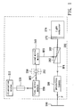
- FIG. 2 shows a top view of one example of the projection display apparatus of FIG. 1 on a X-(-Z) plane
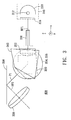
- FIG. 3 shows a side view of the projection display apparatus 300 of FIG. 2 in an X-Y plane
- the light integrator 220 is a light tunnel 320
- the first mirror module 230 includes a first reflective surface, such as a first fold mirror 330
- the second mirror module 240 includes a second reflective surface, being a surface 340 A of a second fold mirror 340 , and a third reflective surface, being a reflective surface of a third fold mirror 350
- the light modulator 270 is a DMD 370 that includes a panel 372 .
- the illumination system 310 includes a lamp that constitutes of a first light source 312 and a housing 314 with reflecting coating, and a color wheel 316 .
- the lamp such as an arc lamp, generates an optical beam to propagate along the first beam path BP 1 in the first direction.
- the color wheel 316 filters the optical beam into primary color components of red, green and blue.
- the light tunnel 320 converts a circular distribution of the optical beam at the entrance into a rectangular distribution at the exit, and simultaneously makes the light intensity distribution more uniform across the optical beam by creating a multiple of virtual images of lamps.
- the beam condensing module 250 contains a plurality of condensers 352 , 354 , 356 and 358 for converging the optical beam.
- the condenser 352 of the beam condensing module is disposed on the first beam path BP 1 for converging the optical beam output from the light tunnel 320 .
- the condensers 354 and 356 are disposed on the second optical beam path BP 2 , and are for converging and focusing the optical beam into the second fold mirror 340 .
- the second fold mirror 340 is for directing the optical beam from condensers 354 and 356 to the third fold mirror 350 .
- the optical beam propagates along beam path P 1 until hitting the third fold mirror 350 , which guides the optical beam towards another direction to propagate along a beam path BP 3 and into the condenser 358 .
- the condenser 358 focuses the optical beam to fit the active area of the panel 372 of the DMD 370 via the total reflection on the prism surface 262 .
- the DMD 370 receiving the optical beam from the second fold mirror 340 via the third fold mirror 350 , the condenser 358 , and the prism surface 262 , is to have the panel 372 illuminated by the received optical beam.
- the DMD 370 selectively reflects the optical beam, such that the reflected beam propagates along a fourth beam path BP 4 in a fourth direction.
- the projection lenses 380 receives the optical beam, which reflects from the DMD 370 and passes through the prism surface 362 , and projects the received optical beam, propagating along a beam path P, onto a display screen (not shown) to display the image.
- the optical beam travels in the first direction passing through the condenser 352 to the first fold mirror 320 , and is directed towards the second direction (Z direction).
- the first direction and the second direction are perpendicular with respect to each other.
- the condenser 356 has an axis A passing (in line with the second beam path BP 2 ) passing through the center of the condenser 356 .
- the third fold mirror 350 is substantially perpendicular to the first fold mirror 330 and parallel to the axis A of the condenser 356 , i.e., the third fold mirror 350 is approximately parallel to X-Z plane.
- the second reflective surface 340 A is capable of directing the optical beam of the second direction (along Z direction) to propagate toward the third reflective surface of the third fold mirror 350 along the beam path P 1 (the beam path P 1 approximately has an included angle 45 degree with the third fold mirror 350 ), and the third reflective surface of the third fold mirror 350 is for directing the optical beam to the third direction (the third beam path BP 3 approximately has an included angle 45 degree with the third fold mirror 350 ).
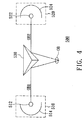
- the illumination system can also be realized with dual lamps, as shown in FIG. 4 .
- the illumination system 500 includes a first lamp 510 , a second lamp 520 , and a beam-combining unit, such as a prism 530 .
- the first lamp 510 has a first light source 512 and a first housing 514 with reflective coating
- the second lamp 520 has a second light source 522 and a second housing 524 with reflective coating.
- the optical beams OB 1 and OB 2 generated by the first light source 512 and the second light source 522 respectively, are reflected by the prism 530 , and combine to generate the optical beam OB, which propagates along the first beam path in the first direction.
- the light tunnel 320 can be hollow or solid.
- the condensers 352 , 354 , 356 , and 358 can be spherical or aspheric, and the mirror module, such as fold mirrors 330 , 340 , and 350 , can be flat or curve.
- the illumination system 210 , the light integrator 220 , the first mirror module 230 are aligned in a line which is almost perpendicular to the beam path BP 4 .
- the disposition of the illumination system 210 , the light integrator 220 allows the packaging size of the projection display apparatus to remain compact, especially in the case of employing dual lamps in the illumination system as shown in FIG. 4 .
- the overall system package can be approximately square-shaped looking from the top side, X-Z plane, thus allowing the display projection apparatus to have a smaller overall dimension, and providing easier carriage by a user during travel.
Abstract
Description
- 1. Field of the Invention
- The invention relates in general to image projection, and more particularly to a projection display apparatus
- 2. Description of the Related Art
- Projection systems are widely used in various applications. A conventional projection system includes a light source, a digital micro-mirror device (DMD), such as one developed by Texas Instruments, and a set of projection lenses. The light source produces a light beam, which is imaged onto the DMD through a set of relay optics. The DMD modulates the light beam and in turn images the modulated light beam, through the projection lenses, onto a display screen to display an image. A color wheel is often used in addition to spatially filter the light beam from the lamp into respective red, green and blue components.
- Due to the increase in business travel, there has been an upsurge in demand for compact projection systems for use in conducting presentations. Accordingly, there is a need to provide a compact projection system to address such demands.
- It is therefore an object of the invention to provide a projection display apparatus, for addressing the aforementioned demands for compact system packaging.
- The invention achieves the above-identified object by providing a projection display apparatus. The apparatus includes an illumination system, a light integrator, a first mirror module, a second mirror module, a beam condensing module, a total internal reflection (TIR) prism, a light modulator, and a set of projection lenses. The illumination system generates an optical beam propagating along a first beam path in a first direction. The light integrator, disposed on the first beam path, is for homogenizing the optical beam. The first mirror module is for directing the optical beam from the light integrator to a second direction, such that the optical beam propagates along a second beam path. The second mirror module is for directing the optical beam from the first mirror module to a third direction, such that the optical beam propagates along a third beam path. The beam condensing module includes at least a condenser, which is disposed on at least one of the first beam path, the second beam path, and the third beam path, for converging the optical beam. The total internal reflection (TIR) prism includes a prism surface and is for receiving the optical beam from the second mirror module. The light modulator includes a panel, and receives the optical beam from the prism surface to illuminate the panel thereof, and selectively reflects the optical beam, such that the reflected optical beam propagates along a fourth beam path in a fourth direction. The projection lenses are for receiving and projecting the optical beam, which is reflected from the light modulator, onto a display screen to display an image. Conditionally, the first beam path and the fourth beam path are substantially perpendicular with respect to each other.
- Other objects, features, and advantages of the invention will become apparent from the following detailed description of the preferred but non-limiting embodiments. The following description is made with reference to the accompanying drawings.
-
FIG. 1 shows a block diagram of a projection display apparatus according to a preferred embodiment of the invention. -
FIG. 2 shows a top view of one example of the projection display apparatus ofFIG. 1 on a X-(-Z) plane -
FIG. 3 shows a side view of theprojection display apparatus 300 ofFIG. 2 in on a X-Y plane. -
FIG. 4 shows a projection display apparatus according to a embodiment of the invention realized with a dual lamp system. -
FIG. 1 shows a block diagram of a projection display apparatus according to a preferred embodiment of the invention. The projection display apparatus includes anillumination system 210, alight integrator 220, afirst mirror module 230, asecond mirror module 240, abeam condensing module 250, aTIR prism 260, alight modulator 270, including apanel 272, and a set ofprojection lenses 280. Theillumination system 210 generates an optical beam to propagate along a first beam path BP1 in a first direction. Thelight integrator 220 is disposed on the first beam path BP1, and homogenizes the optical beam. After passing through thelight integrator 220, the homogenized optical beam reaches the firstmirror module mirror 230, and is directed towards a second direction such that the optical beam propagates along a second beam path BP2. Thebeam condensing module 250 includes at least a condenser which is disposed on at least one of the first optical beam path BP1, the second optical beam path BP2, and a third optical beam path BP3, and converges and focuses the optical beam. InFIG. 1 , it is taken for an example that one condenser of thebeam condensing module 250 is disposed on the second beam path PB2 and focuses the optical beam from thefirst mirror module 230 onto thesecond mirror module 240. Thesecond mirror module 240 directs the optical beam from thefirst mirror module 230 to a third direction, such that the optical beam propagates along the third beam path BP3. Thelight modulator 270 receives the optical beam from thesecond fold mirror 240 via theprism surface 262 ofTIR prism 260 to illuminate thepanel 272 of thelight modulator 270. Thelight modulator 270 selectively reflects the optical beam, such that the reflected beam propagates along a fourth beam path BP4 in a fourth direction. Theprojection lenses 280 receive the optical beam, which is reflected from thelight modulator 270, and projects the received optical beam, traveling a path P, onto thedisplay screen 290 to display an image. The first beam path BP1 and the fourth beam path BP4 are substantially perpendicular with respect to each other. -
FIG. 2 shows a top view of one example of the projection display apparatus ofFIG. 1 on a X-(-Z) plane, andFIG. 3 shows a side view of theprojection display apparatus 300 ofFIG. 2 in an X-Y plane. Thelight integrator 220 is alight tunnel 320. Thefirst mirror module 230 includes a first reflective surface, such as afirst fold mirror 330. Thesecond mirror module 240 includes a second reflective surface, being asurface 340A of asecond fold mirror 340, and a third reflective surface, being a reflective surface of athird fold mirror 350. Thelight modulator 270 is a DMD 370 that includes apanel 372. Theillumination system 310 includes a lamp that constitutes of afirst light source 312 and ahousing 314 with reflecting coating, and acolor wheel 316. The lamp, such as an arc lamp, generates an optical beam to propagate along the first beam path BP1 in the first direction. Thecolor wheel 316 filters the optical beam into primary color components of red, green and blue. Thelight tunnel 320 converts a circular distribution of the optical beam at the entrance into a rectangular distribution at the exit, and simultaneously makes the light intensity distribution more uniform across the optical beam by creating a multiple of virtual images of lamps. - In this example, the
beam condensing module 250 contains a plurality ofcondensers condenser 352 of the beam condensing module is disposed on the first beam path BP1 for converging the optical beam output from thelight tunnel 320. Thecondensers second fold mirror 340. Thesecond fold mirror 340 is for directing the optical beam fromcondensers third fold mirror 350. The optical beam propagates along beam path P1 until hitting thethird fold mirror 350, which guides the optical beam towards another direction to propagate along a beam path BP3 and into thecondenser 358. Thecondenser 358 focuses the optical beam to fit the active area of thepanel 372 of theDMD 370 via the total reflection on theprism surface 262. Thus, theDMD 370, receiving the optical beam from thesecond fold mirror 340 via thethird fold mirror 350, thecondenser 358, and theprism surface 262, is to have thepanel 372 illuminated by the received optical beam. TheDMD 370 selectively reflects the optical beam, such that the reflected beam propagates along a fourth beam path BP4 in a fourth direction. The projection lenses 380 receives the optical beam, which reflects from theDMD 370 and passes through the prism surface 362, and projects the received optical beam, propagating along a beam path P, onto a display screen (not shown) to display the image. - As shown in the
FIG. 3 andFIG. 4 , the optical beam travels in the first direction passing through thecondenser 352 to thefirst fold mirror 320, and is directed towards the second direction (Z direction). Preferably, the first direction and the second direction are perpendicular with respect to each other. Thecondenser 356 has an axis A passing (in line with the second beam path BP2) passing through the center of thecondenser 356. Thethird fold mirror 350 is substantially perpendicular to thefirst fold mirror 330 and parallel to the axis A of thecondenser 356, i.e., thethird fold mirror 350 is approximately parallel to X-Z plane. Therefore, the secondreflective surface 340A is capable of directing the optical beam of the second direction (along Z direction) to propagate toward the third reflective surface of thethird fold mirror 350 along the beam path P1 (the beam path P1 approximately has an included angle 45 degree with the third fold mirror 350), and the third reflective surface of thethird fold mirror 350 is for directing the optical beam to the third direction (the third beam path BP3 approximately has an included angle 45 degree with the third fold mirror 350). - The illumination system can also be realized with dual lamps, as shown in
FIG. 4 . Theillumination system 500 includes afirst lamp 510, asecond lamp 520, and a beam-combining unit, such as aprism 530. Thefirst lamp 510 has a firstlight source 512 and afirst housing 514 with reflective coating, thesecond lamp 520 has a secondlight source 522 and asecond housing 524 with reflective coating. The optical beams OB1 and OB2 generated by the firstlight source 512 and the secondlight source 522, respectively, are reflected by theprism 530, and combine to generate the optical beam OB, which propagates along the first beam path in the first direction. - Additionally, the
light tunnel 320 can be hollow or solid. Thecondensers - Because the first beam path BP1 is designed to be substantially perpendicular to the fourth beam path BP4, the
illumination system 210, thelight integrator 220, thefirst mirror module 230 are aligned in a line which is almost perpendicular to the beam path BP4. The disposition of theillumination system 210, thelight integrator 220 allows the packaging size of the projection display apparatus to remain compact, especially in the case of employing dual lamps in the illumination system as shown inFIG. 4 . By employing the display projection apparatus according to the embodiments of the present invention, the overall system package can be approximately square-shaped looking from the top side, X-Z plane, thus allowing the display projection apparatus to have a smaller overall dimension, and providing easier carriage by a user during travel. - While the invention has been described by way of example and in terms of a preferred embodiment, it is to be understood that the invention is not limited thereto. On the contrary, it is intended to cover various modifications and similar arrangements and procedures, and the scope of the appended claims therefore should be accorded the broadest interpretation so as to encompass all such modifications and similar arrangements and procedures.
Claims (8)
Priority Applications (3)
| Application Number | Priority Date | Filing Date | Title |
|---|---|---|---|
| US11/029,622 US7261422B2 (en) | 2005-01-06 | 2005-01-06 | Display projection apparatus |
| TW094146825A TWI303943B (en) | 2005-01-06 | 2005-12-27 | Projection display apparatus |
| CNA2006100057344A CN1800963A (en) | 2005-01-06 | 2006-01-06 | Display projection apparatus |
Applications Claiming Priority (1)
| Application Number | Priority Date | Filing Date | Title |
|---|---|---|---|
| US11/029,622 US7261422B2 (en) | 2005-01-06 | 2005-01-06 | Display projection apparatus |
Publications (2)
| Publication Number | Publication Date |
|---|---|
| US20060146292A1 true US20060146292A1 (en) | 2006-07-06 |
| US7261422B2 US7261422B2 (en) | 2007-08-28 |
Family
ID=36640010
Family Applications (1)
| Application Number | Title | Priority Date | Filing Date |
|---|---|---|---|
| US11/029,622 Active 2025-08-20 US7261422B2 (en) | 2005-01-06 | 2005-01-06 | Display projection apparatus |
Country Status (3)
| Country | Link |
|---|---|
| US (1) | US7261422B2 (en) |
| CN (1) | CN1800963A (en) |
| TW (1) | TWI303943B (en) |
Cited By (4)
| Publication number | Priority date | Publication date | Assignee | Title |
|---|---|---|---|---|
| US20100238410A1 (en) * | 2009-03-23 | 2010-09-23 | Sanyo Electric Co., Ltd. | Optical element, illumination apparatus, and projection display apparatus |
| CN102890396A (en) * | 2011-07-19 | 2013-01-23 | 台达电子工业股份有限公司 | Projecting apparatus and light source device thereof |
| US20130021583A1 (en) * | 2011-07-19 | 2013-01-24 | Delta Electronics, Inc. | Projection device and light source device thereof |
| CN113329216A (en) * | 2020-02-28 | 2021-08-31 | 苏州佳世达光电有限公司 | Projector with a light source |
Families Citing this family (7)
| Publication number | Priority date | Publication date | Assignee | Title |
|---|---|---|---|---|
| KR100667769B1 (en) * | 2004-08-10 | 2007-01-11 | 삼성전자주식회사 | Projection type image display apparatus |
| TWI307782B (en) * | 2006-05-16 | 2009-03-21 | Delta Electronics Inc | Projector apparatus with multi-light sources and light coupling module thereof |
| US20090303444A1 (en) * | 2008-06-04 | 2009-12-10 | Delta Electronics, Inc. | Projection System |
| JP4924677B2 (en) * | 2009-08-21 | 2012-04-25 | カシオ計算機株式会社 | Light source device, projection device, and projection method |
| DE102012011202A1 (en) | 2012-06-06 | 2013-09-12 | Carl Zeiss Smt Gmbh | Projector for creation of red, blue and green color digital image on screen, has control device for controlling tilting movement of mirrors over radiations reflected from respective mirror on different pixels to control projected image |
| WO2020087195A1 (en) | 2018-10-29 | 2020-05-07 | 陈台国 | Holographic display system and method for forming holographic image |
| CN110639215A (en) * | 2019-10-08 | 2020-01-03 | 凯奇集团有限公司 | Interactive installation based on optics reflection/refraction |
Citations (9)
| Publication number | Priority date | Publication date | Assignee | Title |
|---|---|---|---|---|
| US5467146A (en) * | 1994-03-31 | 1995-11-14 | Texas Instruments Incorporated | Illumination control unit for display system with spatial light modulator |
| US6343864B1 (en) * | 1998-05-20 | 2002-02-05 | Fujitsu General Limited | Liquid crystal projector equipment |
| US20020176054A1 (en) * | 1999-12-30 | 2002-11-28 | Mihalakis George M. | Reflective liquid-crystal-on-silicon projection engine architecture |
| US6505939B1 (en) * | 1999-04-23 | 2003-01-14 | Koninklijke Philips Electronics N.V. | Projection system comprising at least two light sources having a unique optical arrangement with respect to at least one spatial light modulator |
| US6705734B1 (en) * | 1999-11-05 | 2004-03-16 | Sim2 Multimedia S.P.A. | Optic system of illumination for videoprojector |
| US20040141160A1 (en) * | 2002-11-27 | 2004-07-22 | Kazuya Yoneyama | Projection-type image display device |
| US20040246442A1 (en) * | 2003-03-28 | 2004-12-09 | Samsung Electronics Co., Ltd. | Projection type image display system capable of color scrolling |
| US20060187416A1 (en) * | 2000-03-17 | 2006-08-24 | Satoshi Ouchi | Image display device |
| US7101049B2 (en) * | 2003-11-04 | 2006-09-05 | Tamron Co., Ltd. | Projector optics and projector with light source of LEDs |
-
2005
- 2005-01-06 US US11/029,622 patent/US7261422B2/en active Active
- 2005-12-27 TW TW094146825A patent/TWI303943B/en not_active IP Right Cessation
-
2006
- 2006-01-06 CN CNA2006100057344A patent/CN1800963A/en active Pending
Patent Citations (9)
| Publication number | Priority date | Publication date | Assignee | Title |
|---|---|---|---|---|
| US5467146A (en) * | 1994-03-31 | 1995-11-14 | Texas Instruments Incorporated | Illumination control unit for display system with spatial light modulator |
| US6343864B1 (en) * | 1998-05-20 | 2002-02-05 | Fujitsu General Limited | Liquid crystal projector equipment |
| US6505939B1 (en) * | 1999-04-23 | 2003-01-14 | Koninklijke Philips Electronics N.V. | Projection system comprising at least two light sources having a unique optical arrangement with respect to at least one spatial light modulator |
| US6705734B1 (en) * | 1999-11-05 | 2004-03-16 | Sim2 Multimedia S.P.A. | Optic system of illumination for videoprojector |
| US20020176054A1 (en) * | 1999-12-30 | 2002-11-28 | Mihalakis George M. | Reflective liquid-crystal-on-silicon projection engine architecture |
| US20060187416A1 (en) * | 2000-03-17 | 2006-08-24 | Satoshi Ouchi | Image display device |
| US20040141160A1 (en) * | 2002-11-27 | 2004-07-22 | Kazuya Yoneyama | Projection-type image display device |
| US20040246442A1 (en) * | 2003-03-28 | 2004-12-09 | Samsung Electronics Co., Ltd. | Projection type image display system capable of color scrolling |
| US7101049B2 (en) * | 2003-11-04 | 2006-09-05 | Tamron Co., Ltd. | Projector optics and projector with light source of LEDs |
Cited By (7)
| Publication number | Priority date | Publication date | Assignee | Title |
|---|---|---|---|---|
| US20100238410A1 (en) * | 2009-03-23 | 2010-09-23 | Sanyo Electric Co., Ltd. | Optical element, illumination apparatus, and projection display apparatus |
| US8267522B2 (en) * | 2009-03-23 | 2012-09-18 | Sanyo Electric Co., Ltd. | Optical element, illumination apparatus, and projection display apparatus |
| CN102890396A (en) * | 2011-07-19 | 2013-01-23 | 台达电子工业股份有限公司 | Projecting apparatus and light source device thereof |
| US20130021583A1 (en) * | 2011-07-19 | 2013-01-24 | Delta Electronics, Inc. | Projection device and light source device thereof |
| TWI447512B (en) * | 2011-07-19 | 2014-08-01 | Delta Electronics Inc | Projection device and light source device thereof |
| US9033513B2 (en) * | 2011-07-19 | 2015-05-19 | Delta Electronics, Inc. | Projection device and light source device thereof |
| CN113329216A (en) * | 2020-02-28 | 2021-08-31 | 苏州佳世达光电有限公司 | Projector with a light source |
Also Published As
| Publication number | Publication date |
|---|---|
| US7261422B2 (en) | 2007-08-28 |
| CN1800963A (en) | 2006-07-12 |
| TWI303943B (en) | 2008-12-01 |
| TW200625949A (en) | 2006-07-16 |
Similar Documents
| Publication | Publication Date | Title |
|---|---|---|
| US7261422B2 (en) | Display projection apparatus | |
| US9201295B2 (en) | High efficiency LED optical engine for a digital light processing (DLP) projector and method of forming same | |
| US7172290B2 (en) | Light pipe based projection engine | |
| WO2013136563A1 (en) | Projector | |
| WO2006071390A2 (en) | Illumination system with compact turning prism and projection system using same | |
| WO2000038004A1 (en) | Illuminator and projection display | |
| US20070279595A1 (en) | Illumination system and projection system using same | |
| JP4353287B2 (en) | projector | |
| EP0603583A1 (en) | Image projection apparatus | |
| US6783249B2 (en) | Projection-type image display device | |
| US7918561B2 (en) | Projection display device in which position of the light source is shifted toward projection optical system side | |
| JP2002090878A (en) | Projector | |
| WO2006065354A1 (en) | Offset projection system | |
| US7443595B2 (en) | Optical system for projector and imaging method thereof | |
| US6558005B1 (en) | Projection display device comprising an integrator device provided with a tunnel prism | |
| JP2000147658A (en) | Image projector | |
| US20040207769A1 (en) | Projection display device | |
| JP2004286946A (en) | Projector and illumination optical system | |
| CN113329216B (en) | Projector with a light source | |
| JP2002350779A (en) | Illumination optical system, liquid crystal display device and projector | |
| JP2000241917A (en) | Illuminator and projecting device provided therewith | |
| US20060132719A1 (en) | Prism assembly for separating light | |
| JP2022066074A (en) | Projection device | |
| JP2022150729A (en) | projector | |
| JP3506142B1 (en) | Projection display device |
Legal Events
| Date | Code | Title | Description |
|---|---|---|---|
| AS | Assignment |
Owner name: BENQ CORPORATION, TAIWAN Free format text: ASSIGNMENT OF ASSIGNORS INTEREST;ASSIGNOR:LIN, MING-KUEN;REEL/FRAME:016465/0627 Effective date: 20050315 |
|
| STCF | Information on status: patent grant |
Free format text: PATENTED CASE |
|
| AS | Assignment |
Owner name: QISDA CORPORATION, TAIWAN Free format text: CHANGE OF NAME;ASSIGNOR:BENQ CORPORATION;REEL/FRAME:020723/0081 Effective date: 20070831 |
|
| FPAY | Fee payment |
Year of fee payment: 4 |
|
| FPAY | Fee payment |
Year of fee payment: 8 |
|
| MAFP | Maintenance fee payment |
Free format text: PAYMENT OF MAINTENANCE FEE, 12TH YEAR, LARGE ENTITY (ORIGINAL EVENT CODE: M1553); ENTITY STATUS OF PATENT OWNER: LARGE ENTITY Year of fee payment: 12 |