US20070080662A1 - Universal battery module and controller therefor - Google Patents
Universal battery module and controller therefor Download PDFInfo
- Publication number
- US20070080662A1 US20070080662A1 US11/348,056 US34805606A US2007080662A1 US 20070080662 A1 US20070080662 A1 US 20070080662A1 US 34805606 A US34805606 A US 34805606A US 2007080662 A1 US2007080662 A1 US 2007080662A1
- Authority
- US
- United States
- Prior art keywords
- battery
- battery pack
- module
- control
- set forth
- Prior art date
- Legal status (The legal status is an assumption and is not a legal conclusion. Google has not performed a legal analysis and makes no representation as to the accuracy of the status listed.)
- Granted
Links
Images


Classifications
-
- B—PERFORMING OPERATIONS; TRANSPORTING
- B60—VEHICLES IN GENERAL
- B60L—PROPULSION OF ELECTRICALLY-PROPELLED VEHICLES; SUPPLYING ELECTRIC POWER FOR AUXILIARY EQUIPMENT OF ELECTRICALLY-PROPELLED VEHICLES; ELECTRODYNAMIC BRAKE SYSTEMS FOR VEHICLES IN GENERAL; MAGNETIC SUSPENSION OR LEVITATION FOR VEHICLES; MONITORING OPERATING VARIABLES OF ELECTRICALLY-PROPELLED VEHICLES; ELECTRIC SAFETY DEVICES FOR ELECTRICALLY-PROPELLED VEHICLES
- B60L3/00—Electric devices on electrically-propelled vehicles for safety purposes; Monitoring operating variables, e.g. speed, deceleration or energy consumption
- B60L3/0023—Detecting, eliminating, remedying or compensating for drive train abnormalities, e.g. failures within the drive train
- B60L3/0046—Detecting, eliminating, remedying or compensating for drive train abnormalities, e.g. failures within the drive train relating to electric energy storage systems, e.g. batteries or capacitors
-
- B—PERFORMING OPERATIONS; TRANSPORTING
- B60—VEHICLES IN GENERAL
- B60L—PROPULSION OF ELECTRICALLY-PROPELLED VEHICLES; SUPPLYING ELECTRIC POWER FOR AUXILIARY EQUIPMENT OF ELECTRICALLY-PROPELLED VEHICLES; ELECTRODYNAMIC BRAKE SYSTEMS FOR VEHICLES IN GENERAL; MAGNETIC SUSPENSION OR LEVITATION FOR VEHICLES; MONITORING OPERATING VARIABLES OF ELECTRICALLY-PROPELLED VEHICLES; ELECTRIC SAFETY DEVICES FOR ELECTRICALLY-PROPELLED VEHICLES
- B60L50/00—Electric propulsion with power supplied within the vehicle
- B60L50/50—Electric propulsion with power supplied within the vehicle using propulsion power supplied by batteries or fuel cells
- B60L50/60—Electric propulsion with power supplied within the vehicle using propulsion power supplied by batteries or fuel cells using power supplied by batteries
- B60L50/64—Constructional details of batteries specially adapted for electric vehicles
-
- B—PERFORMING OPERATIONS; TRANSPORTING
- B60—VEHICLES IN GENERAL
- B60L—PROPULSION OF ELECTRICALLY-PROPELLED VEHICLES; SUPPLYING ELECTRIC POWER FOR AUXILIARY EQUIPMENT OF ELECTRICALLY-PROPELLED VEHICLES; ELECTRODYNAMIC BRAKE SYSTEMS FOR VEHICLES IN GENERAL; MAGNETIC SUSPENSION OR LEVITATION FOR VEHICLES; MONITORING OPERATING VARIABLES OF ELECTRICALLY-PROPELLED VEHICLES; ELECTRIC SAFETY DEVICES FOR ELECTRICALLY-PROPELLED VEHICLES
- B60L58/00—Methods or circuit arrangements for monitoring or controlling batteries or fuel cells, specially adapted for electric vehicles
- B60L58/10—Methods or circuit arrangements for monitoring or controlling batteries or fuel cells, specially adapted for electric vehicles for monitoring or controlling batteries
- B60L58/12—Methods or circuit arrangements for monitoring or controlling batteries or fuel cells, specially adapted for electric vehicles for monitoring or controlling batteries responding to state of charge [SoC]
- B60L58/14—Preventing excessive discharging
-
- B—PERFORMING OPERATIONS; TRANSPORTING
- B60—VEHICLES IN GENERAL
- B60L—PROPULSION OF ELECTRICALLY-PROPELLED VEHICLES; SUPPLYING ELECTRIC POWER FOR AUXILIARY EQUIPMENT OF ELECTRICALLY-PROPELLED VEHICLES; ELECTRODYNAMIC BRAKE SYSTEMS FOR VEHICLES IN GENERAL; MAGNETIC SUSPENSION OR LEVITATION FOR VEHICLES; MONITORING OPERATING VARIABLES OF ELECTRICALLY-PROPELLED VEHICLES; ELECTRIC SAFETY DEVICES FOR ELECTRICALLY-PROPELLED VEHICLES
- B60L58/00—Methods or circuit arrangements for monitoring or controlling batteries or fuel cells, specially adapted for electric vehicles
- B60L58/10—Methods or circuit arrangements for monitoring or controlling batteries or fuel cells, specially adapted for electric vehicles for monitoring or controlling batteries
- B60L58/12—Methods or circuit arrangements for monitoring or controlling batteries or fuel cells, specially adapted for electric vehicles for monitoring or controlling batteries responding to state of charge [SoC]
- B60L58/15—Preventing overcharging
-
- B—PERFORMING OPERATIONS; TRANSPORTING
- B60—VEHICLES IN GENERAL
- B60L—PROPULSION OF ELECTRICALLY-PROPELLED VEHICLES; SUPPLYING ELECTRIC POWER FOR AUXILIARY EQUIPMENT OF ELECTRICALLY-PROPELLED VEHICLES; ELECTRODYNAMIC BRAKE SYSTEMS FOR VEHICLES IN GENERAL; MAGNETIC SUSPENSION OR LEVITATION FOR VEHICLES; MONITORING OPERATING VARIABLES OF ELECTRICALLY-PROPELLED VEHICLES; ELECTRIC SAFETY DEVICES FOR ELECTRICALLY-PROPELLED VEHICLES
- B60L58/00—Methods or circuit arrangements for monitoring or controlling batteries or fuel cells, specially adapted for electric vehicles
- B60L58/10—Methods or circuit arrangements for monitoring or controlling batteries or fuel cells, specially adapted for electric vehicles for monitoring or controlling batteries
- B60L58/16—Methods or circuit arrangements for monitoring or controlling batteries or fuel cells, specially adapted for electric vehicles for monitoring or controlling batteries responding to battery ageing, e.g. to the number of charging cycles or the state of health [SoH]
-
- B—PERFORMING OPERATIONS; TRANSPORTING
- B60—VEHICLES IN GENERAL
- B60L—PROPULSION OF ELECTRICALLY-PROPELLED VEHICLES; SUPPLYING ELECTRIC POWER FOR AUXILIARY EQUIPMENT OF ELECTRICALLY-PROPELLED VEHICLES; ELECTRODYNAMIC BRAKE SYSTEMS FOR VEHICLES IN GENERAL; MAGNETIC SUSPENSION OR LEVITATION FOR VEHICLES; MONITORING OPERATING VARIABLES OF ELECTRICALLY-PROPELLED VEHICLES; ELECTRIC SAFETY DEVICES FOR ELECTRICALLY-PROPELLED VEHICLES
- B60L58/00—Methods or circuit arrangements for monitoring or controlling batteries or fuel cells, specially adapted for electric vehicles
- B60L58/10—Methods or circuit arrangements for monitoring or controlling batteries or fuel cells, specially adapted for electric vehicles for monitoring or controlling batteries
- B60L58/18—Methods or circuit arrangements for monitoring or controlling batteries or fuel cells, specially adapted for electric vehicles for monitoring or controlling batteries of two or more battery modules
-
- B—PERFORMING OPERATIONS; TRANSPORTING
- B60—VEHICLES IN GENERAL
- B60L—PROPULSION OF ELECTRICALLY-PROPELLED VEHICLES; SUPPLYING ELECTRIC POWER FOR AUXILIARY EQUIPMENT OF ELECTRICALLY-PROPELLED VEHICLES; ELECTRODYNAMIC BRAKE SYSTEMS FOR VEHICLES IN GENERAL; MAGNETIC SUSPENSION OR LEVITATION FOR VEHICLES; MONITORING OPERATING VARIABLES OF ELECTRICALLY-PROPELLED VEHICLES; ELECTRIC SAFETY DEVICES FOR ELECTRICALLY-PROPELLED VEHICLES
- B60L58/00—Methods or circuit arrangements for monitoring or controlling batteries or fuel cells, specially adapted for electric vehicles
- B60L58/10—Methods or circuit arrangements for monitoring or controlling batteries or fuel cells, specially adapted for electric vehicles for monitoring or controlling batteries
- B60L58/24—Methods or circuit arrangements for monitoring or controlling batteries or fuel cells, specially adapted for electric vehicles for monitoring or controlling batteries for controlling the temperature of batteries
- B60L58/26—Methods or circuit arrangements for monitoring or controlling batteries or fuel cells, specially adapted for electric vehicles for monitoring or controlling batteries for controlling the temperature of batteries by cooling
-
- H—ELECTRICITY
- H01—ELECTRIC ELEMENTS
- H01M—PROCESSES OR MEANS, e.g. BATTERIES, FOR THE DIRECT CONVERSION OF CHEMICAL ENERGY INTO ELECTRICAL ENERGY
- H01M10/00—Secondary cells; Manufacture thereof
- H01M10/42—Methods or arrangements for servicing or maintenance of secondary cells or secondary half-cells
- H01M10/425—Structural combination with electronic components, e.g. electronic circuits integrated to the outside of the casing
-
- H—ELECTRICITY
- H01—ELECTRIC ELEMENTS
- H01M—PROCESSES OR MEANS, e.g. BATTERIES, FOR THE DIRECT CONVERSION OF CHEMICAL ENERGY INTO ELECTRICAL ENERGY
- H01M10/00—Secondary cells; Manufacture thereof
- H01M10/42—Methods or arrangements for servicing or maintenance of secondary cells or secondary half-cells
- H01M10/48—Accumulators combined with arrangements for measuring, testing or indicating the condition of cells, e.g. the level or density of the electrolyte
- H01M10/482—Accumulators combined with arrangements for measuring, testing or indicating the condition of cells, e.g. the level or density of the electrolyte for several batteries or cells simultaneously or sequentially
-
- H—ELECTRICITY
- H01—ELECTRIC ELEMENTS
- H01M—PROCESSES OR MEANS, e.g. BATTERIES, FOR THE DIRECT CONVERSION OF CHEMICAL ENERGY INTO ELECTRICAL ENERGY
- H01M10/00—Secondary cells; Manufacture thereof
- H01M10/42—Methods or arrangements for servicing or maintenance of secondary cells or secondary half-cells
- H01M10/48—Accumulators combined with arrangements for measuring, testing or indicating the condition of cells, e.g. the level or density of the electrolyte
- H01M10/486—Accumulators combined with arrangements for measuring, testing or indicating the condition of cells, e.g. the level or density of the electrolyte for measuring temperature
-
- H—ELECTRICITY
- H01—ELECTRIC ELEMENTS
- H01M—PROCESSES OR MEANS, e.g. BATTERIES, FOR THE DIRECT CONVERSION OF CHEMICAL ENERGY INTO ELECTRICAL ENERGY
- H01M10/00—Secondary cells; Manufacture thereof
- H01M10/60—Heating or cooling; Temperature control
- H01M10/61—Types of temperature control
- H01M10/613—Cooling or keeping cold
-
- H—ELECTRICITY
- H01—ELECTRIC ELEMENTS
- H01M—PROCESSES OR MEANS, e.g. BATTERIES, FOR THE DIRECT CONVERSION OF CHEMICAL ENERGY INTO ELECTRICAL ENERGY
- H01M10/00—Secondary cells; Manufacture thereof
- H01M10/60—Heating or cooling; Temperature control
- H01M10/62—Heating or cooling; Temperature control specially adapted for specific applications
- H01M10/625—Vehicles
-
- H—ELECTRICITY
- H01—ELECTRIC ELEMENTS
- H01M—PROCESSES OR MEANS, e.g. BATTERIES, FOR THE DIRECT CONVERSION OF CHEMICAL ENERGY INTO ELECTRICAL ENERGY
- H01M10/00—Secondary cells; Manufacture thereof
- H01M10/60—Heating or cooling; Temperature control
- H01M10/65—Means for temperature control structurally associated with the cells
- H01M10/655—Solid structures for heat exchange or heat conduction
- H01M10/6556—Solid parts with flow channel passages or pipes for heat exchange
-
- H—ELECTRICITY
- H01—ELECTRIC ELEMENTS
- H01M—PROCESSES OR MEANS, e.g. BATTERIES, FOR THE DIRECT CONVERSION OF CHEMICAL ENERGY INTO ELECTRICAL ENERGY
- H01M10/00—Secondary cells; Manufacture thereof
- H01M10/60—Heating or cooling; Temperature control
- H01M10/65—Means for temperature control structurally associated with the cells
- H01M10/656—Means for temperature control structurally associated with the cells characterised by the type of heat-exchange fluid
- H01M10/6567—Liquids
-
- H—ELECTRICITY
- H02—GENERATION; CONVERSION OR DISTRIBUTION OF ELECTRIC POWER
- H02J—CIRCUIT ARRANGEMENTS OR SYSTEMS FOR SUPPLYING OR DISTRIBUTING ELECTRIC POWER; SYSTEMS FOR STORING ELECTRIC ENERGY
- H02J7/00—Circuit arrangements for charging or depolarising batteries or for supplying loads from batteries
- H02J7/00032—Circuit arrangements for charging or depolarising batteries or for supplying loads from batteries characterised by data exchange
- H02J7/00036—Charger exchanging data with battery
-
- H—ELECTRICITY
- H02—GENERATION; CONVERSION OR DISTRIBUTION OF ELECTRIC POWER
- H02J—CIRCUIT ARRANGEMENTS OR SYSTEMS FOR SUPPLYING OR DISTRIBUTING ELECTRIC POWER; SYSTEMS FOR STORING ELECTRIC ENERGY
- H02J7/00—Circuit arrangements for charging or depolarising batteries or for supplying loads from batteries
- H02J7/00047—Circuit arrangements for charging or depolarising batteries or for supplying loads from batteries with provisions for charging different types of batteries
-
- H—ELECTRICITY
- H02—GENERATION; CONVERSION OR DISTRIBUTION OF ELECTRIC POWER
- H02J—CIRCUIT ARRANGEMENTS OR SYSTEMS FOR SUPPLYING OR DISTRIBUTING ELECTRIC POWER; SYSTEMS FOR STORING ELECTRIC ENERGY
- H02J7/00—Circuit arrangements for charging or depolarising batteries or for supplying loads from batteries
- H02J7/0013—Circuit arrangements for charging or depolarising batteries or for supplying loads from batteries acting upon several batteries simultaneously or sequentially
- H02J7/0014—Circuits for equalisation of charge between batteries
-
- H—ELECTRICITY
- H02—GENERATION; CONVERSION OR DISTRIBUTION OF ELECTRIC POWER
- H02J—CIRCUIT ARRANGEMENTS OR SYSTEMS FOR SUPPLYING OR DISTRIBUTING ELECTRIC POWER; SYSTEMS FOR STORING ELECTRIC ENERGY
- H02J7/00—Circuit arrangements for charging or depolarising batteries or for supplying loads from batteries
- H02J7/0047—Circuit arrangements for charging or depolarising batteries or for supplying loads from batteries with monitoring or indicating devices or circuits
- H02J7/0048—Detection of remaining charge capacity or state of charge [SOC]
-
- B—PERFORMING OPERATIONS; TRANSPORTING
- B60—VEHICLES IN GENERAL
- B60L—PROPULSION OF ELECTRICALLY-PROPELLED VEHICLES; SUPPLYING ELECTRIC POWER FOR AUXILIARY EQUIPMENT OF ELECTRICALLY-PROPELLED VEHICLES; ELECTRODYNAMIC BRAKE SYSTEMS FOR VEHICLES IN GENERAL; MAGNETIC SUSPENSION OR LEVITATION FOR VEHICLES; MONITORING OPERATING VARIABLES OF ELECTRICALLY-PROPELLED VEHICLES; ELECTRIC SAFETY DEVICES FOR ELECTRICALLY-PROPELLED VEHICLES
- B60L2240/00—Control parameters of input or output; Target parameters
- B60L2240/10—Vehicle control parameters
- B60L2240/36—Temperature of vehicle components or parts
-
- B—PERFORMING OPERATIONS; TRANSPORTING
- B60—VEHICLES IN GENERAL
- B60L—PROPULSION OF ELECTRICALLY-PROPELLED VEHICLES; SUPPLYING ELECTRIC POWER FOR AUXILIARY EQUIPMENT OF ELECTRICALLY-PROPELLED VEHICLES; ELECTRODYNAMIC BRAKE SYSTEMS FOR VEHICLES IN GENERAL; MAGNETIC SUSPENSION OR LEVITATION FOR VEHICLES; MONITORING OPERATING VARIABLES OF ELECTRICALLY-PROPELLED VEHICLES; ELECTRIC SAFETY DEVICES FOR ELECTRICALLY-PROPELLED VEHICLES
- B60L2240/00—Control parameters of input or output; Target parameters
- B60L2240/40—Drive Train control parameters
- B60L2240/54—Drive Train control parameters related to batteries
- B60L2240/545—Temperature
-
- B—PERFORMING OPERATIONS; TRANSPORTING
- B60—VEHICLES IN GENERAL
- B60L—PROPULSION OF ELECTRICALLY-PROPELLED VEHICLES; SUPPLYING ELECTRIC POWER FOR AUXILIARY EQUIPMENT OF ELECTRICALLY-PROPELLED VEHICLES; ELECTRODYNAMIC BRAKE SYSTEMS FOR VEHICLES IN GENERAL; MAGNETIC SUSPENSION OR LEVITATION FOR VEHICLES; MONITORING OPERATING VARIABLES OF ELECTRICALLY-PROPELLED VEHICLES; ELECTRIC SAFETY DEVICES FOR ELECTRICALLY-PROPELLED VEHICLES
- B60L2240/00—Control parameters of input or output; Target parameters
- B60L2240/40—Drive Train control parameters
- B60L2240/54—Drive Train control parameters related to batteries
- B60L2240/547—Voltage
-
- B—PERFORMING OPERATIONS; TRANSPORTING
- B60—VEHICLES IN GENERAL
- B60L—PROPULSION OF ELECTRICALLY-PROPELLED VEHICLES; SUPPLYING ELECTRIC POWER FOR AUXILIARY EQUIPMENT OF ELECTRICALLY-PROPELLED VEHICLES; ELECTRODYNAMIC BRAKE SYSTEMS FOR VEHICLES IN GENERAL; MAGNETIC SUSPENSION OR LEVITATION FOR VEHICLES; MONITORING OPERATING VARIABLES OF ELECTRICALLY-PROPELLED VEHICLES; ELECTRIC SAFETY DEVICES FOR ELECTRICALLY-PROPELLED VEHICLES
- B60L2240/00—Control parameters of input or output; Target parameters
- B60L2240/40—Drive Train control parameters
- B60L2240/54—Drive Train control parameters related to batteries
- B60L2240/549—Current
-
- H—ELECTRICITY
- H01—ELECTRIC ELEMENTS
- H01M—PROCESSES OR MEANS, e.g. BATTERIES, FOR THE DIRECT CONVERSION OF CHEMICAL ENERGY INTO ELECTRICAL ENERGY
- H01M10/00—Secondary cells; Manufacture thereof
- H01M10/06—Lead-acid accumulators
-
- H—ELECTRICITY
- H01—ELECTRIC ELEMENTS
- H01M—PROCESSES OR MEANS, e.g. BATTERIES, FOR THE DIRECT CONVERSION OF CHEMICAL ENERGY INTO ELECTRICAL ENERGY
- H01M10/00—Secondary cells; Manufacture thereof
- H01M10/60—Heating or cooling; Temperature control
- H01M10/63—Control systems
- H01M10/633—Control systems characterised by algorithms, flow charts, software details or the like
-
- H—ELECTRICITY
- H01—ELECTRIC ELEMENTS
- H01M—PROCESSES OR MEANS, e.g. BATTERIES, FOR THE DIRECT CONVERSION OF CHEMICAL ENERGY INTO ELECTRICAL ENERGY
- H01M10/00—Secondary cells; Manufacture thereof
- H01M10/60—Heating or cooling; Temperature control
- H01M10/64—Heating or cooling; Temperature control characterised by the shape of the cells
- H01M10/647—Prismatic or flat cells, e.g. pouch cells
-
- Y—GENERAL TAGGING OF NEW TECHNOLOGICAL DEVELOPMENTS; GENERAL TAGGING OF CROSS-SECTIONAL TECHNOLOGIES SPANNING OVER SEVERAL SECTIONS OF THE IPC; TECHNICAL SUBJECTS COVERED BY FORMER USPC CROSS-REFERENCE ART COLLECTIONS [XRACs] AND DIGESTS
- Y02—TECHNOLOGIES OR APPLICATIONS FOR MITIGATION OR ADAPTATION AGAINST CLIMATE CHANGE
- Y02E—REDUCTION OF GREENHOUSE GAS [GHG] EMISSIONS, RELATED TO ENERGY GENERATION, TRANSMISSION OR DISTRIBUTION
- Y02E60/00—Enabling technologies; Technologies with a potential or indirect contribution to GHG emissions mitigation
- Y02E60/10—Energy storage using batteries
-
- Y—GENERAL TAGGING OF NEW TECHNOLOGICAL DEVELOPMENTS; GENERAL TAGGING OF CROSS-SECTIONAL TECHNOLOGIES SPANNING OVER SEVERAL SECTIONS OF THE IPC; TECHNICAL SUBJECTS COVERED BY FORMER USPC CROSS-REFERENCE ART COLLECTIONS [XRACs] AND DIGESTS
- Y02—TECHNOLOGIES OR APPLICATIONS FOR MITIGATION OR ADAPTATION AGAINST CLIMATE CHANGE
- Y02P—CLIMATE CHANGE MITIGATION TECHNOLOGIES IN THE PRODUCTION OR PROCESSING OF GOODS
- Y02P70/00—Climate change mitigation technologies in the production process for final industrial or consumer products
- Y02P70/50—Manufacturing or production processes characterised by the final manufactured product
-
- Y—GENERAL TAGGING OF NEW TECHNOLOGICAL DEVELOPMENTS; GENERAL TAGGING OF CROSS-SECTIONAL TECHNOLOGIES SPANNING OVER SEVERAL SECTIONS OF THE IPC; TECHNICAL SUBJECTS COVERED BY FORMER USPC CROSS-REFERENCE ART COLLECTIONS [XRACs] AND DIGESTS
- Y02—TECHNOLOGIES OR APPLICATIONS FOR MITIGATION OR ADAPTATION AGAINST CLIMATE CHANGE
- Y02T—CLIMATE CHANGE MITIGATION TECHNOLOGIES RELATED TO TRANSPORTATION
- Y02T10/00—Road transport of goods or passengers
- Y02T10/60—Other road transportation technologies with climate change mitigation effect
- Y02T10/70—Energy storage systems for electromobility, e.g. batteries
Definitions
- the present invention pertains to energy storage devices, and more particularly, to battery modules and controller therefor.
- High power battery packs are the key components for the successful implementation of electric drive technology in transportation vehicles.
- the battery pack is the main source of power for the pure electric propulsion system and comprises a plurality of series or parallel-connected cells.
- battery packs including a number of acid-lead cells were employed.
- the acid-lead cells were electrically coupled in series to one another to provide sufficient power for the electrical drive mechanism of the early electric vehicles.
- these early battery packs were quite bulky and heavy, and a short life cycle.
- the acid-lead battery packs had a short cycle life, long charge time, and did not provide sufficient battery power over a long range.
- the manufacturers of battery packs have realized that batteries using the nickel-metal hydride cells or lithium-ion cells were lighter and less bulky, with a longer cycle life, faster charging and provided higher output power for longer distances. Accordingly, the nickel-metal hydride or lithium-ion battery packs have become the storage media of choice for high power applications such as electric drive vehicles.
- Another major drawback of the existing battery packs is that the service life of the battery pack is typically shorter than other components of the vehicle. Due to high current drainage and high thermal operating conditions, it is not uncommon for the battery pack to fail and be replaced.
- the vehicle system controller is a component separate from the battery pack itself and outlasts the battery pack. As a result, every time a battery pack is replaced, the vehicle system controller must be calibrated or even replaced so as to correspond with the specifications of the new battery pack.
- the failure of the battery pack may be due to non-ideal performance or breakdown of one or a few individual battery cells within the battery pack, often the entire battery pack is to be replaced, as it is not possible to diagnose and manage the battery cells individually during operation.
- An object of the present invention is to provide a universal battery module that can be easily integrated and used as standard building blocks for battery packs of various sizes and for various applications, such as electric vehicles, wind or solar energy storage devices, or telecommunication equipment.
- the present invention arises from the realization that conventional battery packs used for high power applications such as electric vehicles are designed with the characteristics of the initial load consideration in mind. As a result, if the load capacity is varied or increased, the entire battery pack needs to be redesigned, reconfigured, or replaced to address the power, thermal and mechanical requirements of the new load.
- the present invention seeks to alleviate the shortcomings of existing batter packs by providing a flexible modular power storage platform that allows for interchangeability and expandability.
- the present invention provides a battery pack comprising a plurality of universal battery modules that are each configurable to be thermally, electrically, and mechanically coupled with the other universal battery modules in the battery pack in a modular fashion.
- the battery pack of the present invention can optionally include a controller to monitor the thermal and electrical characteristics of the unit, as well as to regulate and balance the power output of the universal battery modules in accordance with design and operation parameters.
- the battery module of the present invention provides for a scalable and easily expandable battery system.
- the proposed modular design provides for sharing of power and cooling facilities, thus reducing production cost and simplifying manufacturing and reliability.
- a great reduction in vehicle inventory could be achieved if a single, reconfigurable battery module were able to provide equivalent functionality.
- the present invention provides a universal battery module having a plurality of series connected battery cells, sensor means coupled to the cells, the sensor means configured to transmit physical parameters of the cells, and a battery control unit in communication with the sensor means to control the cells based on physical parameters from the sensor means, wherein the battery control unit, the sensor means and the cells are packaged together as a single integral module.
- the present invention provides a battery pack including at least two universal battery modules in a string of connected universal battery modules, each universal battery module including a plurality of series connected battery cells, sensor means coupled to the cells and configured to monitor and transmit physical parameters of the cells, a battery control unit in communication with the sensor means to control the cells based on physical parameters from the sensor means, and a master control module coupled to the string of universal battery modules, the master control module configured to control the battery pack power on/off and including internal electrical connector means to interface with each universal battery modules and control means to control electric equalization of the string of universal battery modules, wherein the string of universal battery modules and the master control module are packaged together as a single integral battery pack.
- FIG. 1 ( a ) is a block diagram showing the components of an electric vehicle including a battery pack having a plurality of UBMs controlled by a MCM according to an embodiment of the present invention
- FIG. 1 ( b ) is a block diagram showing the components of an electric vehicle including a battery pack having a plurality of UBMs according to another embodiment of the present invention
- FIG. 2 is a perspective view of a UBM according to an exemplary embodiment of the present invention.
- FIG. 3 is a flow diagram indicating the steps involved in equalization and charging of cells in the UBM
- FIG. 4 is a perspective view of a MCM according to an exemplary embodiment of the present invention.
- FIG. 5 is a flow diagram indicating the steps involved start-up operation of the MCM
- FIG. 6 is a flow diagram showing the steps in the start-up operation of the UBM
- FIG. 7 a state diagram illustrating various modes of operation of the UBM
- FIG. 8 a state diagram illustrating various modes of operation of the MCM
- FIG. 9 is a top schematic view of a battery pack having two UBMs that are electrically coupled in series with a MCM;
- FIG. 10 is a top schematic view of a battery pack having four UBMs that are electrically coupled in series with no MCM;
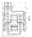
- FIG. 11 is a top schematic view of a battery pack that includes an array of UBMs, wherein two rows of four UBMs are positioned side-by-side.
- sensor is used to define a device having a measurable sensor parameter in response to a characteristic of a measurand, such as temperature, voltage or current.
- controller is used to define a microcontroller having a programmable central processing unit (CPU) and peripheral input/output devices (such as A/D or D/A converters) to monitor parameters from sensors or other devices that are electrically coupled to the controller. These input/output devices can also permit the central processing unit of controller to communicate and control the devices coupled to the controller.
- the controller includes one or more storage media collectively referred to herein as “memory.”
- the memory can be volatile and non-volatile computer memory such as RAM, PROM, EPROM, EEPROM, memory disks, or the like, wherein control programs (such as software, microcode or firmware) for monitoring or controlling the devices coupled to the controller are stored and executed by the CPU.
- the controller also provides the means of converting user-specified operating requirements into control signal to control the peripheral devices coupled to the controller, whereby the controller is configured to receive user-specified commands by way of a user interface such as a keyboard or a graphical user interface (GUI).
- a user interface such as a keyboard or a graphical user interface (GUI).
- GUI graphical user interface
- Control Area Network (CAN) bus is used to define a serial data bus for reliable and high-speed communication of control signals.
- battery equalization is used to describe the operation to equalize the cell voltages under the same conditions (e.g. temperature) during charge or discharge states.
- state-of-charge is used to define the remaining charge of the battery relative to its rated capacity.
- the present invention provides a battery pack having a plurality of electrically coupled UBMs and a MCM for controlling the battery pack.
- Each UBM has rechargeable electric power cells and primitive control circuitry capable of communicating control signals with other UBMS as well as a MCM using standard electrical interfaces and communication protocols over a CAN bus.
- the MCM is an advanced control module, which provides pack safety control and operation control of the high voltage battery pack. Accordingly, the UBMs can be used as generic building blocks for battery packs of various sizes and configurations to accommodate a variety of applications.
- the UBM is capable of simple system control and therefore a battery pack may need no MCM.
- Each UBM can communicate control signals with other UBMs concerning its temperature, cell voltages, module's voltage and module equalization command.
- each UBM is capable of receiving current shunt inputs to monitor the state-of-charge and of sending electrical signals to drive application-related devices such as relays, breakers or contactors, warning light and charge/discharge power controls.
- the MCM At the heart of the MCM is an advanced control unit that monitors the UBMs performance, calculates the pack state-of-charge and provides operating safety control.
- the MCM also includes contactors that are coupled to the control unit and can turn on/off the battery pack.
- the MCM further includes a current shunt, a voltage sensor, and a ground fault sensor coupled to the control unit and can provide readings of battery pack current, voltage and di-electric impedance.
- the MCM has two separated electric connectors that can interface to UBMs and an external system control unit. It collects information from UBMs and report cell voltages, pack temperature distribution, pack state-of-charge, pack current, pack status and malfunction codes to an external control system (such as the control system in an electric vehicle) from which it receives commands to activate contactors accordingly.
- the battery pack comprising the UBMs in accordance with the present invention can be used in a variety of applications that utilize battery power.
- the battery pack is particularly suited for electric vehicles in which electric motive power is employed to drive the vehicle.
- FIG. 1 ( a ) a battery pack 1 a having a plurality of UBMs 2 a to 2 e for use in an electric vehicle.
- the UBMs 2 a to 2 e serve as the basic building block for constructing the battery pack 1 a .
- the UBMs 2 a to 2 e are a rated 24V DC or 36V DC battery modules with built-in intelligent electric control and cooling circuit.
- a typical power control system such as the power control system 3 for an electrical vehicle shown in FIG. 1 ( a )
- a plurality of UMBs 2 a to 2 e is connected in series to form the battery pack 1 a to provide sufficient power to drive the electric vehicle.
- the UBMs 2 a to 2 e are electrically coupled to a MCM 102 , which controls the operation of the entire battery pack 1 a.
- the battery pack 1 a comprising the UBMs is electrically coupled to a charger 5 through a high voltage DC power bus 7 for re-storing energy in the UBMs 2 a to 2 e .
- the charger 5 serves to charge the battery pack 1 a during the charging stage and is a 220VAC to 120VDC power converter with its DC power controlled by charger control signals from MCM 102 .
- the DC power bus 7 carries charging power from the charger 5 to the battery pack 1 a , it also transfers power discharged from the battery pack 1 a to other vehicle devices. Accordingly, during the discharging stage, power stored in the battery pack 1 a is discharged and transferred to an inverter 9 that is electrically coupled to the DC power bus 7 and a traction motor 11 for propelling the vehicle.
- the inverter 9 converts DC power from the battery pack 1 a to AC power to drive the traction motor 11 .
- the traction motor 11 is mechanically coupled to a drive shaft 13 , which transmits mechanical energy to the vehicles wheels 15 and causes the vehicle to advance.
- a power steering pump 17 that is electrically coupled to the DC power bus 7 provides electrical power to the power steering motor 19 of the vehicle.
- a power converter 21 coupled to the DC power bus 7 converts power from the battery pack 1 a and charges the vehicle's battery 23 , which serves to supplement power to various peripheral devices such as the lights 25 , inverter 9 , and instrument cluster 35 of the electric vehicle.
- the DC power bus 7 is a standardized power bus.
- the battery pack 1 a can be easily detached from the power control system 3 for testing or replacement, but also the battery pack 1 a is compatible for use in other systems with different voltage requirements.
- a controller 27 which is electrically coupled to a serial link CAN bus 29 for monitoring the operational status of various devices of the vehicle and to controls the flow of electric power on the DC power bus 7 .
- the controller 27 also controls various operational aspects of the vehicle by communicating control signals over the CAN bus 29 .
- the instrument cluster 35 is electrically coupled to the ontroller 27 by way of the CAN bus 29 and displays information concerning the status of the vehicle and the battery pack 1 a to the vehicle's operator. Preferably, the instrument cluster 35 should indicate all necessary information concerning the safety and reliability of the batter pack 1 a .
- the operator can star-up or shut down the vehicle using the ignition key 37 , or control the vehicle by the accelerator 39 or the brakes 41 that are connected to the controller 27 . Signals from the ignition 37 , accelerator 39 , or brakes 41 are communicated to the controller 27 , which controls the vehicle in accordance with the instructions of the operator.
- pump 43 provides coolant circulation in conduits 45 , 47 to cool and thermally equalize the UBMs 2 a to 2 e.
- FIG. 1 ( b ) there is shown a block diagram showing the components of an electric vehicle including a battery pack having a plurality of UBMs in an exemplary low voltage electric vehicle application.
- the battery pack 1 b shown in FIG. 1 ( b ) is suitable for low voltage applications and includes UBMs 2 a and 2 b .
- the battery pack 1 b is similar to the battery pack 1 a shown in FIG. 1 ( a ), except that unlike the battery pack 1 a , the battery pack 1 b does not include a MCM 102 (shown in FIG. 1 ( a )).
- the UBMs 2 a and 2 b each include a built-in controller (not shown) that can be configured to control the battery pack 1 b .
- the UBM 2 b is responsible for controlling the battery pack 1 b . Not only the UBM 2 b monitor and control its own operational aspects, it also controls and interfaces with several external devices such as the instrument cluster 35 and the ignition key 37 .
- the UBM 2 b receives signals from various sensors such as the shunt current sensor 31 , which communicates the value of the current on the DC power bus 7 to the UBM 2 b.
- a contactor 33 connected to the DC power bus 7 is also electrically coupled to the UBM 2 b and receives control signals from the UBM 2 b . In the event that the operating conditions of the vehicle exceed the safe operating levels, the UBM 2 b opens the contactor 33 to discontinue the flow of power on the DC power bus 7 .
- FIG. 2 shows an exemplary embodiment of a UBM in a battery pack (such as the battery pack 1 a in FIG. 1 ( a )) according to the present invention.
- the UBM 2 shown in FIG. 2 includes a shell 4 coupled to a base plate 8 in a preferably hermetically sealed relationship to prevent moisture from penetrating the shell 4 .
- the shell 4 contains therein a plurality of electrochemical battery cells 6 that are transversely positioned within a thermal frame 20 in a side-by-side fashion.
- the thermal frame 20 is in intimate contact with the cells 6 and is thermally coupled to base plate 8 to drive heat away from the cells 6 .
- the thermal frame 20 retains the cells 6 in thermal relationship to provide thermal balancing between the cells 6 .
- the thermal frame 20 will distribute the excess heat throughout its frame thereby preventing a hotspot to occur.
- the thermal frame 20 is made of thermal conductive materials such as aluminum that equalize the temperature between cells 6 .
- the base plate 8 is further configured to include channels (not shown) that are fluidly connected to inlet 10 and outlet 12 to allow liquid coolant circulate in the base plate 8 for improved heat dissipation.
- the UBM 2 also includes a liquid cooling circuit that cools each cell 6 in the UBM 2 by circulating a liquid coolant around the thermal frame 20 .
- the cells 6 are electrically connected to one another in a series configuration by way of voltage conductors 50 .
- the cells 6 are Lithium-ion battery cells that are connected in series to provide the voltage in the range of 24V DC or 36V DC through the anode 16 and cathode 18 terminals of the UBM 2 .
- the cells 6 can be connected in parallel, or a parallel series combination.
- the UBM 2 is operational between two different states, namely a charge state, and a discharge state.
- a charge state the UBM 2 terminal voltage will increase when its state-of-charge increases by converting electric energy into chemical charges stored in the cells 6 .
- the UBM 2 voltage goes down when its state-of-charge decreases and releases the stored energy.
- a bypass resister 48 is connected across the terminals of the cell 6 to bypass the charge or discharge current.
- the bypass resistor 48 reduces the charge current.
- the bypass resister 48 acts to reduce the discharge current.
- Each UBM 2 in a battery pack (such as the battery pack 1 a shown in FIG. 1 ( a )) comprises identical control logic and functional capabilities for self-initiated control of the physical parameters of the local UBM 2 .
- the UBM 2 includes a Battery Control Unit (BCU) 14 that monitors the cell 6 voltages and module temperature, controls voltage equalizations between cells 6 and communicates various information regarding status of the UBM 2 during charge and discharge states to other UBMs 2 and the master control module MCM which is described in further detail in connection with FIG. 4 hereinafter.
- BCU Battery Control Unit
- the BCU 14 is implemented using a controller as defined herein.
- the BCU's 14 memory includes predefined values for the temperature and voltage thresholds of the UBM 2 .
- the predefined values are stored in the BCU 14 memory in a look-up table.
- the BCU 14 is electrically coupled to a connector 24 to communicate signals corresponding to the operating status of the UBM 2 to a MCM, or other UBMs 2 in a battery pack.
- the connector 24 protrudes from the shell 4 and provides terminals 26 to 46 for connection with a serial communication CAN bus, for instance the CAN bus 29 in FIG. 1 ( a ).
- the connector 24 can be configured such that it would directly connect with a mating connector from a subsequent UBM 2 in a battery pack.
- the BCU 14 transmits electrical control signals corresponding to various aspects of the UBM 2 over the serial communication CAN bus such as the CAN bus 29 in FIG. 1 ( a ) that is electrically coupled to terminals 26 to 46 in order to transmit or receive control signals from peripheral devices in a power control system.
- the control signals are adapted to drive relays, contactors, or similar actuating devices.
- each BCU 14 needs a communication channel for passing its control signals to other BCUs 14 in the battery pack. This can be achieved by coupling terminals 26 and 28 of each BCU 14 to a serial communication bus such as the CAN bus 51 shown in FIG. 1 ( a ), which serves as the main communications channel for the various BCUs 14 in the battery pack.
- the BCUs 14 can optionally communicate with each other on the serial communication CAN bus using a master or a proprietary CAN communication protocol.
- control signals can be used to provide basic system control without using an external controller for controlling the entire battery pack.
- the control signals will not be used (not connected) when building a large battery pack with an internal MCM for controlling various operational aspects of the battery pack.
- the signals available at terminals 26 to 46 are summarized in the Table 1 below: TABLE 1 UBM terminal description Terminal Function Control Signals 26 CAN+ CAN Bus, UBM voltage, current 28 CAN ⁇ State-of-Charge, di-electric impedance, fault code, etc.
- Ignition Ignition On/Off 32 Warning Flashing when charging Light Solid when over or under voltage or over temperature 34
- Power Charger control Control 36
- Sequence UP Input signal for automatic numbering 38
- Sequence Output signal for automatic numbering DOWN 40
- GND Chassis ground 42
- Contactor Contactor control, Safety control 44
- Diff IN+ Shunt current sensor Differential input+ 46
- the connector 24 further communicates other control signals generated from the BCU 14 , such as a contactor signal at terminal 42 , a warning light signal at terminal 32 , and power control signal at terminal 34 to provide simple system operation control and differential shunt voltage inputs Diff IN+ 44 , and Diff IN ⁇ 46 to measure the current of the battery pack (such as the battery pack 1 b shown in FIG. 1 ( b )).
- the current shunt 35 communicates the value of the current on DC power bus 7 .
- Terminal 36 communicates a “sequence UP” signal from the BCU 14 that is the input to the present UBM 2 enable/disable the sequence number arbitration of UBM 2 within the battery pack.
- Terminal 38 indicates a “sequence Down” signal from the BCU 14 that is the output to enable/disable the next adjacent UBM 2 to arbitrate the sequence number of the UBM 2 in the plurality of UBMs 2 in a battery pack for an external controller to recognize it.
- the single UBM 2 with no “sequence Up” input connection is considered as the first UBM 2 which will be responsible for simple system control. This is the case with UBM 2 b described in FIG. 1 ( b ).
- a heat sensor 22 (such as a thermostat) is provided to monitor the heat generated by the cells 6 .
- the heat sensor 22 is in thermal relationship with the thermal frame 20 and electrically connected to the BCU 14 .
- the BCU 14 constantly monitors the temperature of the UBM 2 and compares the temperature with the predefined acceptable threshold stored in the BCU 14 . There are two levels of threshold: (i) warning threshold; and (ii) off threshold.
- the BCU 14 will first sends a warning flag on signal at terminals 26 and 28 so as to communicate the warning flag via the CAN bus 29 to the controller 27 (as shown in FIG. 1 ( a )). The BCU 14 will only shut down the UBM 2 if the temperature continues to rise pass the threshold.
- the BCU 14 sends the warning light signal at terminal 32 with its duty cycle in reverse of the battery pack state-of-charge. For instance, when state-of-charge is larger than 60%, the warning light 32 is set to duty cycle 2%; when state-of-charge is 5%, the warning light 32 duty cycle is 99%. Similarly, when the BCU 14 detects that the operating temperature of the UBM 2 exceeds a safety limit, the state-of-charge is less than 3% or that the UBM 2 is over voltage or under voltage, it will keep the warning light signal at a duty cycle of 99%.
- the warning light signal at terminal 32 is optionally transmitted to a warning light 52 that is connected to terminal 32 , which would indicate a solid light when the UBM 2 is over or under voltage, over discharged, or when the temperature of the UBM 2 exceeds the predetermined thresholds.
- the module power control signal available at terminal 34 is set at 98% duty cycle. If any cell 6 voltage is closer to a predetermined constant voltage set point, the power control signal duty cycle will start reducing down to 2%.
- This signal can be used to control a charger (such as charger 5 shown in FIG. 1 ( a )) coupled to the UBM 2 whose charging power is proportional to its control input signal duty cycle.
- a charger such as charger 5 shown in FIG. 1 ( a )
- the charger output power is reducing and therefore no cell 6 voltage will exceed the constant voltage set point.
- a proportional integral derivative (PID) algorithm is implemented in BCU 14 in software or firmware, which constantly monitors the voltage and maintains the cell voltage below a set point.
- a current shunt 35 can be electrically connected in series to the battery pack's output power terminal 18 to provide differential feedback to BCU 14 , thereby allowing the BCU 14 to monitor the current characteristics of the battery pack in either the charge or discharge states.
- This current shunt 35 is electrically coupled to BCU 14 through terminals Diff IN+ 44 , and Diff IN ⁇ 46 and communicates the current characteristics to the BCU 14 for monitoring the battery state-of-charge.
- FIG. 3 shows a flow diagram indicating the steps involved in equalization and charging of cells 6 by BCU 14 .
- These steps can be implemented in BCU 14 by firmware or software in BCU 14 .
- the BCU 14 enters the operation mode wherein it continuously monitors the cell equalization status.
- the BCU 14 will enter cell electric equalization mode to equalize the cells 6 (e.g. turn on the bypass circuit of those cells 6 whose voltage is above or below the average voltage of the cells 6 within the UBM 2 with a predetermined error).
- the BCU 14 continuously reports the maximum and minimum cell 6 voltages as well as UBM 2 temperature via the serial communication CAN bus 29 (shown in FIG. 1 ( a )). Accordingly, the BCU 14 first calculates the average cell 6 voltages to determine the average cell voltage V ave (Step S 12 ). The BCU 14 then verifies whether the cells 6 have been in the charging state for more than 2 seconds (Step S 14 ). If the cells 6 have been charged for over 2 seconds, the BCU 14 compares the voltage V i of each cell 6 with the average voltage V ave plus the voltage threshold (Step S 16 ).
- Step S 18 If the cell 6 voltage V i is larger than the combination of average voltage V ave plus the voltage threshold, the BCU 14 switches on a bypass circuit BC i for that particular cell 6 , so as to bypass some current from charging the cell 6 .
- Step S 20 if the cell 6 voltage V i is within the voltage threshold, the BCU 14 shuts off the bypass circuit BC i 48 for that cell 6 (Step S 20 ).
- the BCU 14 subsequently determines the maximum cell voltage V max ⁇ i for the cell 6 (Step S 22 ).
- Dv corresponds to the difference between the charge cell 6 voltage set point V sp (T) for the current operating temperature T of the UBM 2 , and the V max ⁇ i for the cell 6 (Step S 24 ).
- the BCU 14 sets the charger's duty cycle from the PID algorithm. The duty cycle is set not to exceed 98% or fall below 2% (Step S 26 ).
- Step S 28 the BCU 14 checks to see whether the cells 6 have been discharging for more than 1 second. In the event the cells 6 have not been discharging for over 1 second, then all the bypass circuits within the UBM 2 are turned off (Step S 30 ) and the charger's (such as charger 5 in FIG. 1 ( a )) duty cycle set to 2% (Step S 32 ).
- a power control signal is used to indicate the maximum discharge power allowed. Therefore, if the cells 6 have been discharging for over 1 second, discharge state is confirmed and the power control signal duty cycle is set as a percentage of the current discharge power over the maximum allowed discharge power (Step S 38 ).
- the BCU 14 compares the voltage V i of each cell 6 with the average voltage V ave plus the voltage threshold (Step S 34 ). If the cell 6 voltage V i is smaller than the combination of average voltage V ave plus the voltage threshold, the BCU 14 activates the bypass circuit BC i for the cell 6 in order to bypass some current from discharging the cell 6 (Step S 36 ). However, if the cell 6 voltage V i is within the voltage threshold, the BCU 14 shuts off the bypass circuit BC i for that cell 6 (Step S 40 ).
- FIG. 4 illustrates a Master Control Module (MCM) 102 for controlling a battery pack (such the battery pack 1 a shown in FIG. 1 ( a )).
- MCM Master Control Module
- the MCM 102 is an interface and control module that monitors operating parameters of the entire battery pack and manages the UBM 2 resources to achieve the safe operation of the battery pack.
- the MCM 102 includes internal positive 120 and negative 122 power terminals, external power positive 108 and negative 106 terminals, and a controller coupled to a first connector 112 for internal serial communication with at least a UBM 2 in a battery pack (not shown in FIG. 4 ).
- the MCM 102 communicates control signals with the UBMs 2 by way of a serial communication link, such as CAN bus, that is coupled to the terminals of the connector 112 .
- a serial communication link such as CAN bus
- the MCM 102 further includes a second connector 110 for external serial communication with various peripheral devices such as the battery charger in a system. Accordingly, the MCM 102 separates the external serial communication with the internal serial communication with two serial buses CAN 1 bus 113 and CAN 2 bus 111 coupled to the first connector 112 and second connectors respectively 110 , respectively.
- the MCM 102 and its interfaces include the following signals sa described in Table 2 below: TABLE 2 MCM terminal description Terminal Function Control Signals 128 CAN+ CAN Bus 130 CAN ⁇ CAN Bus 132 Ignition Ignition On/Off 134 Warning Flashing when charging Light Solid when over or under voltage or over temperature 136 Power Charger control Control 138 Safety Energized during operation Interlock+ 140 Safety Energized during operation Interlock ⁇ 142 GND Chassis ground
- the MCM 102 also includes a main contactor 124 , a precharge contactor 126 , a current shunt 116 , a fuse 118 and a controller 114 that includes a di-electrical impedance detection circuitry. It supports battery packs of voltages above 72V with internal CAN 1 bus 113 isolated from the CAN 2 bus 111 which interfaces directly to the system control serial communication bus.
- the MCM 102 optionally includes a fuse that will disconnect the power to the battery pack when the battery pack is short-circuited. It can switch onloff the high voltage bus by built-in contactors 124 , 126 , which are controlled according to CAN, command or power on signal.
- the safety interlock terminals 138 , 140 are to enable the closing of the built-in contactors 124 , 126 . Only when energized, the contactors 124 , 126 can be closed to output power or accept charges. This protection allows the high voltage power from the battery pack to be cut off in emergency by a physical switch.
- the UBM 2 is generally maintained in a voltage range during the charge stage so as to prevent over voltage during charging and maximizing the charging of the battery pack.
- the MCM 102 monitors both the cell 6 (shown in FIG. 1 ( a )) voltages and the charging current supplied to the battery pack comprising a number of UBMs 2 (such as UBMs 2 a to 2 e in battery pack 1 a shown in FIG. 1 ( a )) and controls the charging power via power control signal 136 during a charge cycle so as to prevent overcharging of the battery pack.
- the MCM 102 can also be configured and arranged to send an electrical signal to drive the warning light and charger.
- the MCM 102 is configured to further monitor the battery pack charge/discharge current and high voltage bus di-electric impedance level (Ohm) with a SAE recommended circuit (not shown).
- a voltage sensor is provided to determine the voltage from the battery pack. Accordingly, the MCM 102 can also monitor the battery pack instantaneous and average voltage based on sensed voltage communicated to the MCM 102 by the voltage sensor.
- FIG. 5 illustrates the steps in the start-up operation of the MCM 102 shown in FIG. 4 .
- the MCM 102 monitors the CAN 2 bus 111 to determine whether a CAN signal has been received on CAN 2 111 (Step S 52 ). If a CAN signal has been initiated from the power control system (such as the power control system 3 shown in FIG.
- the MCM 102 retrieves from its memory the: (i) Saved time when the pack is switched off; (ii) the pack state-of-charge from last switched off; (iii) accumulated Energy In and Out in the battery pack's life; (iv) accumulated Operating Time in the battery pack's life; and (v) Accumulated Fault Codes in the battery pack's life (Step S 54 ).
- the MCM 102 then calculates the resting time of the battery pack (Step S 56 ) since it was last switched off.
- the MCM 102 resolves whether the rest time exceeds a predetermined time frame, for instance 3 hours (Step S 58 ).
- the MCM 102 obtains the battery pack open circuit voltage V oc (Step S 60 ), on the basis of which, it calculates a new SOC for the battery pack (Step S 64 ).
- the MCM 102 proceeds to obtain the di-electric impedance R di of the battery pack (Step S 66 ).
- the MCM 102 uses the saved SOC operation value (Step S 68 ) as the new SOC value.
- the new SOC is used for columbic integration calculation (Step S 64 ) as the initial value and directly proceeds to obtain from the di-electric detection circuit 114 the di-electric impedance R di of the battery pack (Step S 66 ).
- the MCM 102 proceeds to measure the di-electric impedance R di of the battery pack (Step S 66 ) and communicates the di-electric impedance R di on the CAN bus (Step S 70 ) and compares the di-electric impedance R di with the threshold value (Step S 72 ). If the di-electric impedance R di is less than the threshold value, the MCM 102 sets a warning flag and communicates the flag via the CAN bus. The MCM 102 then checks whether there is a power up command on the CAN 2 bus 111 (Step S 76 ).
- the MCM 102 will wait the power up/down command via CAN 2 bus 111 from the system controller (Step S 76 , S 78 ). If there is a power up command on the CAN 2 bus 111 , then the MCM 102 switches on the precharge contactor (Step S 80 ), otherwise it will wait for a the power up command from CAN 2 bus 111 (Step S 76 ).
- the MCM 102 monitors the battery pack output voltage V c and the precharging time (Step S 82 ). If the output voltage V c is larger than 90% of a threshold voltage level V oc (Step S 84 ), then the MCM 102 activates the main contactor (Step S 86 ), sets startup flag and updates via the CAN bus 111 (Step S 88 ), and saves the start-up time from the built-in real-time clock (Step S 90 ). If the output voltage V c is less than 90% of the V oc (Step S 84 ), the MCM 102 verifies whether the precharging timer is timeout (Step S 92 ).
- the MCM 102 MCM 102 monitors the battery pack output voltage V c and monitors the waiting time (Step S 82 ). In the event that the timer is timeout, the MCM 102 sets fail precharge flag and updates via the CAN 2 bus 111 (Step S 94 ) and switches off the precharge contactor (Step S 96 ).
- FIG. 6 illustrates the steps in the start-up operation of a UBM 2 .
- the UBM 2 monitors a CAN bus coupled to the BCU 14 terminals 26 and 28 . If there is a MCM 102 present in the battery pack, its CAN 1 bus 113 (shown in FIG. 4 ) is coupled to the BCU 14 terminals 26 and 28 .
- the BCU 14 monitors the CAN 1 bus 113 and waits for a CAN command placed on the CAN 1 bus 113 by the MCM 102 or other UBMs 2 in the battery pack (Step S 102 ).
- the BCU 14 will further check whether it is the first UBM 2 (i.e. no MCM 102 in the battery pack) in the pack (Step S 104 ).
- the BCU 14 retrieves from its memory the: (i) accumulated Operating Time in the battery pack's life; and (ii) Accumulated Fault Codes in the battery pack's life (Step S 126 ) and finalizes the startup process (Step S 128 ).
- the UBM 2 is the first UBM, its BCU 14 has to initialize to provide battery pack control functions.
- the BCU 14 therefore retrieves from its memory (i) Saved time when the pack is switched off; (ii) the pack state-of-charge from last switched off; (iii) accumulated Energy In and Out in the battery pack's life (Step S 106 ).
- the BCU 14 To determine the initial SOC, the BCU 14 first calculates the battery pack resting time (Step S 108 ). The BCU 14 then checks whether the battery pack has been inactive for over 3 hours (Step S 110 ). If the battery pack rested for not longer than 3 hours, the BCU 14 uses the saved SOC value as the initial integration value to calculate battery pack SOC during the following operation (Step S 118 ). If the battery pack rested for longer than 3 hours, the BCU 14 will read the pack open circuit voltage (Step S 112 ) and use it to calculate the new SOC (Step S 114 ) as the initial integration value to calculate pack SOC during the following operation (Step S 116 ).
- BCU 14 After finishing initial SOC calculation, BCU 14 will initialize the battery pack by saving the startup time to its memory for later use to calculate operation time (Step S 120 ) and reset warning light signal duty cycle to 3% (warning light off) and reset power control signal duty cycle to 2% (charger power off) (Step S 122 ).
- BCU 14 When the above initialization completed, BCU 14 will switch on the contactor (Step S 124 ) to supply power (e.g. for vehicle driving) or receive charging.
- the BCU 14 retrieves from its memory the: (i) accumulated Operating Time in the pack's life; and (ii) Accumulated Fault Codes in the pack's life (Step S 126 ) to complete the startup processing (Step S 128 ).
- FIG. 7 a state diagram illustrating various modes of operation of a UBM 2 shown in FIG. 2 .
- the UBM 2 may operate in the following modes: (i) initialization mode 301 ; (ii) operation mode 302 ; (iii) service mode 304 ; (iv) sleep mode 306 ; and (v) control mode 308 in operation.
- the BCU 14 reboots.
- the BCU 14 will reload the parameters include CAN communication baud rate and repetition rate and conduct module sequence number arbitrations.
- the BCU 14 will continuously monitor the cell 6 voltages and UBM 2 temperature. Base on the cell 6 voltage distribution, the BCU 14 may turn on/off cell equalization bypass circuits to equalize the cell 6 voltages. When over voltage of any cell 6 or over temperature of the UBM 2 are detected, the BCU 14 sends alarm signals through CAN 1 bus 113 .
- the BCU 14 also sends data (such as information concerning the cells 6 voltage or temperature) periodically to the MCM 102 .
- data such as information concerning the cells 6 voltage or temperature
- the BCU 14 will sample all the cell 6 voltages and report via CAN 1 bus 113 immediately.
- a global equalization command is received by the BCU 14 from the CAN 1 bus 113 , all the cell 6 equalization circuits will be turned on until removal of the command.
- the BCU 14 for the first UBM 2 will open the contactor 33 if the alarm flags from CAN 1 bus 113 from any UBM 2 exists continuously for more than three updates of the CAN messages or more than three UBMs 2 report the alarms at the same time, and turns on the warning light when over voltage of any cell 6 or over temperature of the UBM 2 are detected.
- the BCU 14 can upload new software (or firmware) or update the parameters to its memory.
- the new uploaded software or parameters won't take effect until the next time the UBM 2 enters into the initialization mode 301 .
- the BCU 14 reloads the new software or parameters and re-initializes itself to its new configurations, reloads the new version of software.
- the BCU 14 is configured to transmit via the CAN 1 bus 133 operating status information (such as cell 6 voltages, UBM 2 temperature, current operating parameters, error codes, etc.) for diagnostics purposes.
- UBM 2 During the sleep mode 306 , at ignition off (i.e. terminal 30 of the BCU 14 ), UBM 2 enters sleep mode for energy conservation and to reduce the power consumption. While in the sleep mode 306 , all BCUs 14 (include CPU, CAN transceiver and power regulators) will enter sleep mode and can be woken up at ignition power on.
- the UBM 2 determines that it is the first module (with no enable input) in a battery pack and there is no MCM 102 , it enters the control mode 308 .
- the BCU 14 not only controls the UBM 2 as in operation mode 302 but also monitors the battery pack current via shunt differential inputs and controls the warning light, contactor and power control to provide basic power on/off and charging control.
- the BCU 14 also transmits control signals such as synchronized voltage measurement or global equalization over the CAN bus to other UBMs 2 for battery pack equalization. In a preferred embodiment, these control signals can be communicated to an instrumentation cluster (such as the instrument cluster 35 shown in FIG. 1 ( a )) for display of the battery pack state-of-charge and fault status.
- FIG. 8 shows a state diagram illustrating various modes of operation of the MCM 102 of FIG. 4 .
- the MCM 102 modes of operation are as follows: (i) initialization mode 401 ; (ii) operation mode 402 ; (iii) sleep mode; and (iv) service mode.
- the MCM 102 For first time power up at Start-up mode 400 , the MCM 102 enters the initialization mode 401 , whereby it reloads saved parameters (such as CAN bus baud rate, CAN communication update rate, SOC, accumulated charge/discharge columbic, accumulated working hours, etc.) and fault information from last power on cycle.
- saved parameters such as CAN bus baud rate, CAN communication update rate, SOC, accumulated charge/discharge columbic, accumulated working hours, etc.
- the MCM 102 controls basic battery pack operations, namely, module equalization, system precharge and main power on/off. At the same time the MCM 102 monitors the battery pack current, voltage and high voltage bus dielectric impedance, and calculates battery pack SOC and charge/discharge capacity. It reports these values regularly with operating modes as well as fault status via CAN 2 bus 111 to the power control system (such as the power control system 3 shown in FIG. 1 ( a )).
- the power control system such as the power control system 3 shown in FIG. 1 ( a )
- MCM 102 can upload new software (or firmware) or update the parameters to its memory. The new uploaded software or parameters won't take effect until the next time the MCM 102 enters into the initialization mode 401 . If the reset command is present on the CAN 2 bus 111 , the MCM 102 reloads the new software or parameters and re-initializes itself to its new configurations. Moreover, during the service mode 404 , the MCM 102 is configured to transmit via the CAN 2 bus 111 operating status information concerning the UBM 2 (UBM 2 voltage and current, UBM 2 temperature, error codes, etc.) for diagnostics purposes.
- UBM 2 UBM 2 voltage and current, UBM 2 temperature, error codes, etc.
- the MCM 102 In the sleep mode 406 , the MCM 102 enters sleep mode to save power consumption. At the same time, it will keep the real time clock working to track the rest and operation time of the battery pack.
- a battery pack 60 having two UBMs 2 a and 2 b that are electrically coupled in series.
- Such a battery pack 60 is suitable for low voltage applications, such as All-Terrain-Vehicles (ATVs), golf carts, or scooters for the physically challenged.
- the battery pack 60 includes UBMs 2 a , 2 b having BCU 14 a , 14 b , respectively.
- BCU 14 a and 14 b communicate with each other through connectors 24 a , 24 b through a serial communication bus 25 .
- the BCU 14 b uses its standard control outputs to provide basic control of the UBMs 2 a , 2 b .
- a connector 62 is electrically connected with connector 24 b to communicate control signals from the UBM 2 b to an external bus (not shown).
- an external bus is typically not present. In these applications, there may be no external serial bus communication during operation except for services such as diagnostics, software update, calibration update, etc. by connecting an external controller such as a Personal Computer equipped with a CAN card to the CAN 1 bus 113 .
- the CAN communication terminals 26 and 28 are used for service operation control only, and include software or parameter upload/download and system reset.
- the power on signals (Ignition 30 and GND 40 ) are the operation control signals with Diff IN+ 44 , and Diff IN ⁇ 46 indicating the pack 60 current.
- a heat sink (not shown) can optionally be thermally coupled to the battery pack shell 61 which thermally contacts tightly with battery module base plates to improve heat dissipation.
- FIG. 10 shows a perspective view of a battery pack 70 having four UBMs 2 a , 2 b , 2 c , and 2 d that are electrically coupled in series, having BCU 14 a , 14 b , 14 c , and 14 d , respectively.
- the battery pack 70 is a high voltage pack that requires a MCM 102 to provide high voltage protections and battery pack power on/off control. It is suitable for high power applications, such as pure electric vehicles, hybrid electric vehicles, wind or solar energy storages. All the BUCs 14 a , 14 b , 14 c , and 14 d communicate with each other using the CAN 2 bus 83 , 81 .
- the MCM 102 has its input power terminals 120 and 122 connected to the power terminals 18 d and 16 d of UBM 14 d respectively.
- the MCM 102 output power terminals 108 and 106 are the battery pack's 70 power interface.
- the MCM 102 communicates with the external devices such as the power control system 3 in FIG. 1 ( a ) via connector 110 which has the same signals as those described in Table 2.
- the MCM 102 interfaces with UBM 2 d by internal electric connector 112 with signals include: (i) Sequence enable 85 ; (ii) CAN+ 83 ; (iii) CAN ⁇ 81 ; (iv)Power On/Off 91 ; and (v) Signal ground 89 .
- UBMs' 2 a to 2 d system control signals such as those described in Table 1 namely the warning light 32 , power control 34 , contactor control 42 , Diff IN+ 44 , and Diff IN ⁇ 46 are not required and therefore will not be connected and used.
- the battery pack 70 requires liquid cooling with coolant in 45 and coolant out 47 for the purpose of both thermal cooling and thermal equalization between the UBMs 2 a to 2 d.
- each battery pack comprises a single linear array of UBMs in series.
- the battery pack 80 includes an array of UBMs 2 a to 2 h , wherein two rows of four UBMs 2 a to 2 d , and 2 e to 2 h are retained side-by-side.
- the UBMs 2 a to 2 h of each row are aligned proximate to each other with their respective inlets 10 a to 10 h and outlets 12 a to 12 h are in alignment to permits improved flow of coolant within the cooling system.
- the UBMs 2 a to 2 d are connected to one another in parallel.
- the UBMs 2 e to 2 h are connected to one another in parallel.
- the UBMs 2 a to 2 d in the first row are connected to the UBMs 2 e to 2 h in the second row in series.
- the UBM 2 d is connected to a MCM 102 , which is responsible for controlling the entire battery pack 80 .
Abstract
Description
- The present invention pertains to energy storage devices, and more particularly, to battery modules and controller therefor.
- With the advent of high power, high performance electric drive technology, transportation vehicles are increasingly being moved from the combustion engine platform to electric propulsion systems. Not only electric vehicles are more power efficient and robust due to their lesser number of internal components, but also they produce little or no environmentally harmful emissions associated with the ignition of fossil fuels in combustion engines.
- High power battery packs are the key components for the successful implementation of electric drive technology in transportation vehicles. The battery pack is the main source of power for the pure electric propulsion system and comprises a plurality of series or parallel-connected cells. Initially, battery packs including a number of acid-lead cells were employed. The acid-lead cells were electrically coupled in series to one another to provide sufficient power for the electrical drive mechanism of the early electric vehicles. However, these early battery packs were quite bulky and heavy, and a short life cycle. Moreover, the acid-lead battery packs had a short cycle life, long charge time, and did not provide sufficient battery power over a long range.
- In order to overcome some of these limitations, the manufacturers of battery packs have realized that batteries using the nickel-metal hydride cells or lithium-ion cells were lighter and less bulky, with a longer cycle life, faster charging and provided higher output power for longer distances. Accordingly, the nickel-metal hydride or lithium-ion battery packs have become the storage media of choice for high power applications such as electric drive vehicles.
- In spite of the enormous success of the nickel-metal hydride battery packs, these devices suffer from the drawback that they are typically custom-designed for a specific application, having regard to the mechanical, thermal and electrical design constraints that are specific to the application. As a result, these battery packs are not interchangeable and cannot be readily integrated in other vehicles or high power applications.
- Another major drawback of the existing battery packs is that the service life of the battery pack is typically shorter than other components of the vehicle. Due to high current drainage and high thermal operating conditions, it is not uncommon for the battery pack to fail and be replaced. The vehicle system controller is a component separate from the battery pack itself and outlasts the battery pack. As a result, every time a battery pack is replaced, the vehicle system controller must be calibrated or even replaced so as to correspond with the specifications of the new battery pack. Moreover, although the failure of the battery pack may be due to non-ideal performance or breakdown of one or a few individual battery cells within the battery pack, often the entire battery pack is to be replaced, as it is not possible to diagnose and manage the battery cells individually during operation.
- This background information is provided to reveal information believed by the applicant to be of possible relevance to the present invention. No admission is necessarily intended, nor should be construed, that any of the preceding information constitutes prior art against the present invention.
- An object of the present invention is to provide a universal battery module that can be easily integrated and used as standard building blocks for battery packs of various sizes and for various applications, such as electric vehicles, wind or solar energy storage devices, or telecommunication equipment.
- It is a further object of this invention to provide battery modules with high volume production that are suitable for building battery packs of high performance and long life.
- It is yet another object of the present invention to provide a master control module for power management of the universal battery modules in a battery pack.
- The present invention arises from the realization that conventional battery packs used for high power applications such as electric vehicles are designed with the characteristics of the initial load consideration in mind. As a result, if the load capacity is varied or increased, the entire battery pack needs to be redesigned, reconfigured, or replaced to address the power, thermal and mechanical requirements of the new load. The present invention seeks to alleviate the shortcomings of existing batter packs by providing a flexible modular power storage platform that allows for interchangeability and expandability. The present invention provides a battery pack comprising a plurality of universal battery modules that are each configurable to be thermally, electrically, and mechanically coupled with the other universal battery modules in the battery pack in a modular fashion. The battery pack of the present invention can optionally include a controller to monitor the thermal and electrical characteristics of the unit, as well as to regulate and balance the power output of the universal battery modules in accordance with design and operation parameters.
- The battery module of the present invention provides for a scalable and easily expandable battery system. The proposed modular design provides for sharing of power and cooling facilities, thus reducing production cost and simplifying manufacturing and reliability. In addition, a great reduction in vehicle inventory could be achieved if a single, reconfigurable battery module were able to provide equivalent functionality.
- In a first aspect, the present invention provides a universal battery module having a plurality of series connected battery cells, sensor means coupled to the cells, the sensor means configured to transmit physical parameters of the cells, and a battery control unit in communication with the sensor means to control the cells based on physical parameters from the sensor means, wherein the battery control unit, the sensor means and the cells are packaged together as a single integral module.
- In another aspect, the present invention provides a battery pack including at least two universal battery modules in a string of connected universal battery modules, each universal battery module including a plurality of series connected battery cells, sensor means coupled to the cells and configured to monitor and transmit physical parameters of the cells, a battery control unit in communication with the sensor means to control the cells based on physical parameters from the sensor means, and a master control module coupled to the string of universal battery modules, the master control module configured to control the battery pack power on/off and including internal electrical connector means to interface with each universal battery modules and control means to control electric equalization of the string of universal battery modules, wherein the string of universal battery modules and the master control module are packaged together as a single integral battery pack.
- Other aspects and features of the present invention will become apparent to those ordinarily skilled in the art upon review of the following description of specific embodiments of the invention in conjunction with the accompanying figures.
- A better understanding of these and other embodiments of the present invention can be obtained with reference to the following drawings which show by way of example embodiments of the present invention, in which:
-
FIG. 1 (a) is a block diagram showing the components of an electric vehicle including a battery pack having a plurality of UBMs controlled by a MCM according to an embodiment of the present invention; -
FIG. 1 (b) is a block diagram showing the components of an electric vehicle including a battery pack having a plurality of UBMs according to another embodiment of the present invention; -
FIG. 2 is a perspective view of a UBM according to an exemplary embodiment of the present invention; -
FIG. 3 is a flow diagram indicating the steps involved in equalization and charging of cells in the UBM; -
FIG. 4 is a perspective view of a MCM according to an exemplary embodiment of the present invention; -
FIG. 5 is a flow diagram indicating the steps involved start-up operation of the MCM; -
FIG. 6 is a flow diagram showing the steps in the start-up operation of the UBM; -
FIG. 7 a state diagram illustrating various modes of operation of the UBM; -
FIG. 8 a state diagram illustrating various modes of operation of the MCM; -
FIG. 9 is a top schematic view of a battery pack having two UBMs that are electrically coupled in series with a MCM; -
FIG. 10 is a top schematic view of a battery pack having four UBMs that are electrically coupled in series with no MCM; and -
FIG. 11 is a top schematic view of a battery pack that includes an array of UBMs, wherein two rows of four UBMs are positioned side-by-side. - The term “sensor” is used to define a device having a measurable sensor parameter in response to a characteristic of a measurand, such as temperature, voltage or current.
- The term “controller” is used to define a microcontroller having a programmable central processing unit (CPU) and peripheral input/output devices (such as A/D or D/A converters) to monitor parameters from sensors or other devices that are electrically coupled to the controller. These input/output devices can also permit the central processing unit of controller to communicate and control the devices coupled to the controller. The controller includes one or more storage media collectively referred to herein as “memory.” The memory can be volatile and non-volatile computer memory such as RAM, PROM, EPROM, EEPROM, memory disks, or the like, wherein control programs (such as software, microcode or firmware) for monitoring or controlling the devices coupled to the controller are stored and executed by the CPU. Optionally, the controller also provides the means of converting user-specified operating requirements into control signal to control the peripheral devices coupled to the controller, whereby the controller is configured to receive user-specified commands by way of a user interface such as a keyboard or a graphical user interface (GUI).
- The term Control Area Network (CAN) bus is used to define a serial data bus for reliable and high-speed communication of control signals.
- The term battery equalization is used to describe the operation to equalize the cell voltages under the same conditions (e.g. temperature) during charge or discharge states.
- The term state-of-charge is used to define the remaining charge of the battery relative to its rated capacity.
- Unless defined otherwise, all technical and scientific terms used herein have the same meaning as commonly understood by one of ordinary skill in the art to which this invention belongs.
- Generally, the present invention provides a battery pack having a plurality of electrically coupled UBMs and a MCM for controlling the battery pack. Each UBM has rechargeable electric power cells and primitive control circuitry capable of communicating control signals with other UBMS as well as a MCM using standard electrical interfaces and communication protocols over a CAN bus. The MCM is an advanced control module, which provides pack safety control and operation control of the high voltage battery pack. Accordingly, the UBMs can be used as generic building blocks for battery packs of various sizes and configurations to accommodate a variety of applications.
- The UBM is capable of simple system control and therefore a battery pack may need no MCM. Each UBM can communicate control signals with other UBMs concerning its temperature, cell voltages, module's voltage and module equalization command. When working without MCM in a battery pack, each UBM is capable of receiving current shunt inputs to monitor the state-of-charge and of sending electrical signals to drive application-related devices such as relays, breakers or contactors, warning light and charge/discharge power controls.
- At the heart of the MCM is an advanced control unit that monitors the UBMs performance, calculates the pack state-of-charge and provides operating safety control. The MCM also includes contactors that are coupled to the control unit and can turn on/off the battery pack. The MCM further includes a current shunt, a voltage sensor, and a ground fault sensor coupled to the control unit and can provide readings of battery pack current, voltage and di-electric impedance.
- The MCM has two separated electric connectors that can interface to UBMs and an external system control unit. It collects information from UBMs and report cell voltages, pack temperature distribution, pack state-of-charge, pack current, pack status and malfunction codes to an external control system (such as the control system in an electric vehicle) from which it receives commands to activate contactors accordingly.
- Exemplary embodiments of the present invention are now described with reference to accompanying drawings, wherein like elements are designated by like reference numerals throughout the drawings.
- Universal Battery Module
- Due to its expandability and interchangeability, the battery pack comprising the UBMs in accordance with the present invention can be used in a variety of applications that utilize battery power. The battery pack is particularly suited for electric vehicles in which electric motive power is employed to drive the vehicle.
- There is shown in
FIG. 1 (a) abattery pack 1 a having a plurality ofUBMs 2 a to 2 e for use in an electric vehicle. TheUBMs 2 a to 2 e serve as the basic building block for constructing thebattery pack 1 a. TheUBMs 2 a to 2 e are a rated 24V DC or 36V DC battery modules with built-in intelligent electric control and cooling circuit. In a typical power control system such as thepower control system 3 for an electrical vehicle shown inFIG. 1 (a), a plurality ofUMBs 2 a to 2 e is connected in series to form thebattery pack 1 a to provide sufficient power to drive the electric vehicle. TheUBMs 2 a to 2 e are electrically coupled to aMCM 102, which controls the operation of theentire battery pack 1 a. - The
battery pack 1 a comprising the UBMs is electrically coupled to acharger 5 through a high voltageDC power bus 7 for re-storing energy in theUBMs 2 a to 2 e. Thecharger 5 serves to charge thebattery pack 1 a during the charging stage and is a 220VAC to 120VDC power converter with its DC power controlled by charger control signals fromMCM 102. Not only theDC power bus 7 carries charging power from thecharger 5 to thebattery pack 1 a, it also transfers power discharged from thebattery pack 1 a to other vehicle devices. Accordingly, during the discharging stage, power stored in thebattery pack 1 a is discharged and transferred to aninverter 9 that is electrically coupled to theDC power bus 7 and atraction motor 11 for propelling the vehicle. Theinverter 9 converts DC power from thebattery pack 1 a to AC power to drive thetraction motor 11. Thetraction motor 11 is mechanically coupled to adrive shaft 13, which transmits mechanical energy to thevehicles wheels 15 and causes the vehicle to advance. Similarly, apower steering pump 17 that is electrically coupled to theDC power bus 7 provides electrical power to thepower steering motor 19 of the vehicle. Apower converter 21 coupled to theDC power bus 7 converts power from thebattery pack 1 a and charges the vehicle'sbattery 23, which serves to supplement power to various peripheral devices such as thelights 25,inverter 9, andinstrument cluster 35 of the electric vehicle. - Advantageously, the
DC power bus 7 is a standardized power bus. As a result, not only thebattery pack 1 a can be easily detached from thepower control system 3 for testing or replacement, but also thebattery pack 1 a is compatible for use in other systems with different voltage requirements. - At the heart of the
control system 3 is acontroller 27, which is electrically coupled to a serial link CANbus 29 for monitoring the operational status of various devices of the vehicle and to controls the flow of electric power on theDC power bus 7. Thecontroller 27 also controls various operational aspects of the vehicle by communicating control signals over theCAN bus 29. - The
instrument cluster 35 is electrically coupled to theontroller 27 by way of theCAN bus 29 and displays information concerning the status of the vehicle and thebattery pack 1 a to the vehicle's operator. Preferably, theinstrument cluster 35 should indicate all necessary information concerning the safety and reliability of thebatter pack 1 a. The operator can star-up or shut down the vehicle using theignition key 37, or control the vehicle by theaccelerator 39 or thebrakes 41 that are connected to thecontroller 27. Signals from theignition 37,accelerator 39, orbrakes 41 are communicated to thecontroller 27, which controls the vehicle in accordance with the instructions of the operator. - In a high power application such as the electric vehicle control system shown in
FIG. 1 (a), heat dissipation becomes an important concern. Accordingly, pump 43 provides coolant circulation inconduits UBMs 2 a to 2 e. - Referring now to
FIG. 1 (b), there is shown a block diagram showing the components of an electric vehicle including a battery pack having a plurality of UBMs in an exemplary low voltage electric vehicle application. Thebattery pack 1 b shown inFIG. 1 (b) is suitable for low voltage applications and includesUBMs battery pack 1 b is similar to thebattery pack 1 a shown inFIG. 1 (a), except that unlike thebattery pack 1 a, thebattery pack 1 b does not include a MCM 102 (shown inFIG. 1 (a)). Instead, theUBMs battery pack 1 b. In the presently described embodiment, theUBM 2 b is responsible for controlling thebattery pack 1 b. Not only theUBM 2 b monitor and control its own operational aspects, it also controls and interfaces with several external devices such as theinstrument cluster 35 and theignition key 37. - The
UBM 2 b receives signals from various sensors such as the shunt current sensor 31, which communicates the value of the current on theDC power bus 7 to theUBM 2 b. - A
contactor 33 connected to theDC power bus 7 is also electrically coupled to theUBM 2 b and receives control signals from theUBM 2 b. In the event that the operating conditions of the vehicle exceed the safe operating levels, theUBM 2 b opens thecontactor 33 to discontinue the flow of power on theDC power bus 7. - Reference is now made to
FIG. 2 , which shows an exemplary embodiment of a UBM in a battery pack (such as thebattery pack 1 a inFIG. 1 (a)) according to the present invention. TheUBM 2 shown inFIG. 2 includes ashell 4 coupled to abase plate 8 in a preferably hermetically sealed relationship to prevent moisture from penetrating theshell 4. Theshell 4 contains therein a plurality ofelectrochemical battery cells 6 that are transversely positioned within athermal frame 20 in a side-by-side fashion. Thethermal frame 20 is in intimate contact with thecells 6 and is thermally coupled tobase plate 8 to drive heat away from thecells 6. Moreover, thethermal frame 20 retains thecells 6 in thermal relationship to provide thermal balancing between thecells 6. Accordingly, if the temperature of aparticular cell 6 abnormally rises during operation due to malfunction, thethermal frame 20 will distribute the excess heat throughout its frame thereby preventing a hotspot to occur. Advantageously, thethermal frame 20 is made of thermal conductive materials such as aluminum that equalize the temperature betweencells 6. - In one embodiment, the
base plate 8 is further configured to include channels (not shown) that are fluidly connected toinlet 10 andoutlet 12 to allow liquid coolant circulate in thebase plate 8 for improved heat dissipation. In another embodiment, theUBM 2 also includes a liquid cooling circuit that cools eachcell 6 in theUBM 2 by circulating a liquid coolant around thethermal frame 20. - The
cells 6 are electrically connected to one another in a series configuration by way ofvoltage conductors 50. In the presently described embodiment, thecells 6 are Lithium-ion battery cells that are connected in series to provide the voltage in the range of 24V DC or 36V DC through theanode 16 andcathode 18 terminals of theUBM 2. However, as it can be appreciated by those skilled in the art, thecells 6 can be connected in parallel, or a parallel series combination. - The
UBM 2 is operational between two different states, namely a charge state, and a discharge state. During the charge state, theUBM 2 terminal voltage will increase when its state-of-charge increases by converting electric energy into chemical charges stored in thecells 6. During the discharge state, theUBM 2 voltage goes down when its state-of-charge decreases and releases the stored energy. - For each
cell 6, abypass resister 48 is connected across the terminals of thecell 6 to bypass the charge or discharge current. When acell 6 voltage is higher than others during the charge state, thebypass resistor 48 reduces the charge current. When acell 6 voltage is lower than others during the discharge state, thebypass resister 48 acts to reduce the discharge current. - Each
UBM 2 in a battery pack (such as thebattery pack 1 a shown inFIG. 1 (a)) comprises identical control logic and functional capabilities for self-initiated control of the physical parameters of thelocal UBM 2. Accordingly, theUBM 2 includes a Battery Control Unit (BCU) 14 that monitors thecell 6 voltages and module temperature, controls voltage equalizations betweencells 6 and communicates various information regarding status of theUBM 2 during charge and discharge states toother UBMs 2 and the master control module MCM which is described in further detail in connection withFIG. 4 hereinafter. - In the presently described embodiment of the invention, the
BCU 14 is implemented using a controller as defined herein. The BCU's 14 memory includes predefined values for the temperature and voltage thresholds of theUBM 2. The predefined values are stored in theBCU 14 memory in a look-up table. TheBCU 14 is electrically coupled to aconnector 24 to communicate signals corresponding to the operating status of theUBM 2 to a MCM, orother UBMs 2 in a battery pack. - The
connector 24 protrudes from theshell 4 and providesterminals 26 to 46 for connection with a serial communication CAN bus, for instance theCAN bus 29 inFIG. 1 (a). Alternatively, theconnector 24 can be configured such that it would directly connect with a mating connector from asubsequent UBM 2 in a battery pack. Throughterminals 26 to 46, theBCU 14 transmits electrical control signals corresponding to various aspects of theUBM 2 over the serial communication CAN bus such as theCAN bus 29 inFIG. 1 (a) that is electrically coupled toterminals 26 to 46 in order to transmit or receive control signals from peripheral devices in a power control system. Preferably, the control signals are adapted to drive relays, contactors, or similar actuating devices. - In a battery pack comprising a plurality of
UBMs 2 such as theUBMs 2 a to 2 e in thebattery pack 1 a shown inFIG. 1 (a), eachBCU 14 needs a communication channel for passing its control signals toother BCUs 14 in the battery pack. This can be achieved bycoupling terminals BCU 14 to a serial communication bus such as theCAN bus 51 shown inFIG. 1 (a), which serves as the main communications channel for thevarious BCUs 14 in the battery pack. TheBCUs 14 can optionally communicate with each other on the serial communication CAN bus using a master or a proprietary CAN communication protocol. - For small applications that need low voltage battery system, these control signals can be used to provide basic system control without using an external controller for controlling the entire battery pack. The control signals will not be used (not connected) when building a large battery pack with an internal MCM for controlling various operational aspects of the battery pack. The signals available at
terminals 26 to 46 are summarized in the Table 1 below:TABLE 1 UBM terminal description Terminal Function Control Signals 26 CAN+ CAN Bus, UBM voltage, current 28 CAN− State-of-Charge, di-electric impedance, fault code, etc. 30 Ignition Ignition On/ Off 32 Warning Flashing when charging Light Solid when over or under voltage or over temperature 34 Power Charger control Control 36 Sequence UP Input signal for automatic numbering 38 Sequence Output signal for automatic numbering DOWN 40 GND Chassis ground 42 Contactor Contactor control, Safety control 44 Diff IN+ Shunt current sensor Differential input+ 46 Diff IN− Shunt current sensor Differential input− - As indicated in Table 1, The
connector 24 further communicates other control signals generated from theBCU 14, such as a contactor signal atterminal 42, a warning light signal atterminal 32, and power control signal atterminal 34 to provide simple system operation control and differential shunt voltageinputs Diff IN+ 44, and Diff IN− 46 to measure the current of the battery pack (such as thebattery pack 1 b shown inFIG. 1 (b)). For example, in the low voltage application ofFIG. 1 (b), thecurrent shunt 35 communicates the value of the current onDC power bus 7.Terminal 36 communicates a “sequence UP” signal from theBCU 14 that is the input to thepresent UBM 2 enable/disable the sequence number arbitration ofUBM 2 within the battery pack. Terminal 38 indicates a “sequence Down” signal from theBCU 14 that is the output to enable/disable the nextadjacent UBM 2 to arbitrate the sequence number of theUBM 2 in the plurality ofUBMs 2 in a battery pack for an external controller to recognize it. In the event there are only twoUBM 2 in the battery pack, thesingle UBM 2 with no “sequence Up” input connection is considered as thefirst UBM 2 which will be responsible for simple system control. This is the case withUBM 2 b described inFIG. 1 (b). - High power batteries, particularly those used in automotive applications such as the one shown in FIGs. 1(a) and 1(b), generate tremendous amounts of heat during operation. Not only the heat reduces the life of the
cells 6, but also it is hazardous to safe operation of the system incorporating thepower system 3. To control the thermal characteristics of theUBM 2, a heat sensor 22 (such as a thermostat) is provided to monitor the heat generated by thecells 6. Theheat sensor 22 is in thermal relationship with thethermal frame 20 and electrically connected to theBCU 14. TheBCU 14 constantly monitors the temperature of theUBM 2 and compares the temperature with the predefined acceptable threshold stored in theBCU 14. There are two levels of threshold: (i) warning threshold; and (ii) off threshold. If theUBM 2 temperature exceeds the predefined warning threshold, theBCU 14 will first sends a warning flag on signal atterminals CAN bus 29 to the controller 27 (as shown inFIG. 1 (a)). TheBCU 14 will only shut down theUBM 2 if the temperature continues to rise pass the threshold. - The
BCU 14 sends the warning light signal at terminal 32 with its duty cycle in reverse of the battery pack state-of-charge. For instance, when state-of-charge is larger than 60%, thewarning light 32 is set toduty cycle 2%; when state-of-charge is 5%, thewarning light 32 duty cycle is 99%. Similarly, when theBCU 14 detects that the operating temperature of theUBM 2 exceeds a safety limit, the state-of-charge is less than 3% or that theUBM 2 is over voltage or under voltage, it will keep the warning light signal at a duty cycle of 99%. The warning light signal atterminal 32 is optionally transmitted to awarning light 52 that is connected toterminal 32, which would indicate a solid light when theUBM 2 is over or under voltage, over discharged, or when the temperature of theUBM 2 exceeds the predetermined thresholds. - Under normal operating conditions, the module power control signal available at
terminal 34 is set at 98% duty cycle. If anycell 6 voltage is closer to a predetermined constant voltage set point, the power control signal duty cycle will start reducing down to 2%. This signal can be used to control a charger (such ascharger 5 shown inFIG. 1 (a)) coupled to theUBM 2 whose charging power is proportional to its control input signal duty cycle. When the control signal duty cycle is reducing, the charger output power is reducing and therefore nocell 6 voltage will exceed the constant voltage set point. A proportional integral derivative (PID) algorithm is implemented inBCU 14 in software or firmware, which constantly monitors the voltage and maintains the cell voltage below a set point. - As shown in
FIG. 1 (b), acurrent shunt 35 can be electrically connected in series to the battery pack'soutput power terminal 18 to provide differential feedback toBCU 14, thereby allowing theBCU 14 to monitor the current characteristics of the battery pack in either the charge or discharge states. Thiscurrent shunt 35 is electrically coupled toBCU 14 throughterminals Diff IN+ 44, and Diff IN− 46 and communicates the current characteristics to theBCU 14 for monitoring the battery state-of-charge. - Reference is now made to
FIG. 3 , which shows a flow diagram indicating the steps involved in equalization and charging ofcells 6 byBCU 14. These steps can be implemented inBCU 14 by firmware or software inBCU 14. For the purposes ofFIG. 3 , it is assumed that there areN cells 6 in a battery pack. When the power on signal atterminal 30 is detected (Step S10), theBCU 14 enters the operation mode wherein it continuously monitors the cell equalization status. When during charging thecell 6 voltages become diversified, theBCU 14 will enter cell electric equalization mode to equalize the cells 6 (e.g. turn on the bypass circuit of thosecells 6 whose voltage is above or below the average voltage of thecells 6 within theUBM 2 with a predetermined error). At the same time, theBCU 14 continuously reports the maximum andminimum cell 6 voltages as well asUBM 2 temperature via the serial communication CAN bus 29 (shown inFIG. 1 (a)). Accordingly, theBCU 14 first calculates theaverage cell 6 voltages to determine the average cell voltage Vave (Step S12). TheBCU 14 then verifies whether thecells 6 have been in the charging state for more than 2 seconds (Step S14). If thecells 6 have been charged for over 2 seconds, theBCU 14 compares the voltage Vi of eachcell 6 with the average voltage Vave plus the voltage threshold (Step S16). - If the
cell 6 voltage Vi is larger than the combination of average voltage Vave plus the voltage threshold, theBCU 14 switches on a bypass circuit BCi for thatparticular cell 6, so as to bypass some current from charging thecell 6. (Step S18). However, if thecell 6 voltage Vi is within the voltage threshold, theBCU 14 shuts off the bypass circuit BCi 48 for that cell 6 (Step S20). TheBCU 14 subsequently determines the maximum cell voltage Vmax−i for the cell 6 (Step S22). At this juncture, theBCU 14 determines Dv according to the following equation: Dv=Vsp(T)−Vmax−i, whereby Dv corresponds to the difference between thecharge cell 6 voltage set point Vsp(T) for the current operating temperature T of theUBM 2, and the Vmax−i for the cell 6 (Step S24). On the basis of the Dv, theBCU 14 sets the charger's duty cycle from the PID algorithm. The duty cycle is set not to exceed 98% or fall below 2% (Step S26). - If the
cells 6 have not been charged for over 2 seconds, theBCU 14 then checks to see whether thecells 6 have been discharging for more than 1 second (Step S28). In the event thecells 6 have not been discharging for over 1 second, then all the bypass circuits within theUBM 2 are turned off (Step S30) and the charger's (such ascharger 5 inFIG. 1 (a)) duty cycle set to 2% (Step S32). - During the discharge state, a power control signal is used to indicate the maximum discharge power allowed. Therefore, if the
cells 6 have been discharging for over 1 second, discharge state is confirmed and the power control signal duty cycle is set as a percentage of the current discharge power over the maximum allowed discharge power (Step S38). - If the
cells 6 have been discharging for over 1 second, then theBCU 14 compares the voltage Vi of eachcell 6 with the average voltage Vave plus the voltage threshold (Step S34). If thecell 6 voltage Vi is smaller than the combination of average voltage Vave plus the voltage threshold, theBCU 14 activates the bypass circuit BCi for thecell 6 in order to bypass some current from discharging the cell 6 (Step S36). However, if thecell 6 voltage Vi is within the voltage threshold, theBCU 14 shuts off the bypass circuit BCi for that cell 6 (Step S40). - Master Control Module
- Reference is now made to
FIG. 4 , which illustrates a Master Control Module (MCM) 102 for controlling a battery pack (such thebattery pack 1 a shown inFIG. 1 (a)). TheMCM 102 is an interface and control module that monitors operating parameters of the entire battery pack and manages theUBM 2 resources to achieve the safe operation of the battery pack. - As illustrated in
FIG. 4 , theMCM 102 includes internal positive 120 and negative 122 power terminals, external power positive 108 and negative 106 terminals, and a controller coupled to afirst connector 112 for internal serial communication with at least aUBM 2 in a battery pack (not shown inFIG. 4 ). TheMCM 102 communicates control signals with theUBMs 2 by way of a serial communication link, such as CAN bus, that is coupled to the terminals of theconnector 112. - The
MCM 102 further includes asecond connector 110 for external serial communication with various peripheral devices such as the battery charger in a system. Accordingly, theMCM 102 separates the external serial communication with the internal serial communication with two serial buses CAN1 bus 113 andCAN2 bus 111 coupled to thefirst connector 112 and second connectors respectively 110, respectively. TheMCM 102 and its interfaces, include the following signals sa described in Table 2 below:TABLE 2 MCM terminal description Terminal Function Control Signals 128 CAN+ CAN Bus 130 CAN− CAN Bus 132 Ignition Ignition On/ Off 134 Warning Flashing when charging Light Solid when over or under voltage or over temperature 136 Power Charger control Control 138 Safety Energized during operation Interlock+ 140 Safety Energized during operation Interlock− 142 GND Chassis ground - The
MCM 102 also includes amain contactor 124, aprecharge contactor 126, acurrent shunt 116, afuse 118 and acontroller 114 that includes a di-electrical impedance detection circuitry. It supports battery packs of voltages above 72V with internal CAN1 bus 113 isolated from theCAN2 bus 111 which interfaces directly to the system control serial communication bus. TheMCM 102 optionally includes a fuse that will disconnect the power to the battery pack when the battery pack is short-circuited. It can switch onloff the high voltage bus by built-incontactors - The
safety interlock terminals contactors contactors - The
UBM 2 is generally maintained in a voltage range during the charge stage so as to prevent over voltage during charging and maximizing the charging of the battery pack. TheMCM 102 monitors both the cell 6 (shown inFIG. 1 (a)) voltages and the charging current supplied to the battery pack comprising a number of UBMs 2 (such asUBMs 2 a to 2 e inbattery pack 1 a shown inFIG. 1 (a)) and controls the charging power viapower control signal 136 during a charge cycle so as to prevent overcharging of the battery pack. - The
MCM 102 can also be configured and arranged to send an electrical signal to drive the warning light and charger. Advantageously, theMCM 102 is configured to further monitor the battery pack charge/discharge current and high voltage bus di-electric impedance level (Ohm) with a SAE recommended circuit (not shown). In another embodiment, a voltage sensor is provided to determine the voltage from the battery pack. Accordingly, theMCM 102 can also monitor the battery pack instantaneous and average voltage based on sensed voltage communicated to theMCM 102 by the voltage sensor. - Reference is now made to
FIG. 5 , which illustrates the steps in the start-up operation of theMCM 102 shown inFIG. 4 . Initially, theMCM 102 monitors theCAN2 bus 111 to determine whether a CAN signal has been received on CAN2 111 (Step S52). If a CAN signal has been initiated from the power control system (such as thepower control system 3 shown inFIG. 1 (a)), theMCM 102 retrieves from its memory the: (i) Saved time when the pack is switched off; (ii) the pack state-of-charge from last switched off; (iii) accumulated Energy In and Out in the battery pack's life; (iv) accumulated Operating Time in the battery pack's life; and (v) Accumulated Fault Codes in the battery pack's life (Step S54). TheMCM 102 then calculates the resting time of the battery pack (Step S56) since it was last switched off. TheMCM 102 resolves whether the rest time exceeds a predetermined time frame, forinstance 3 hours (Step S58). If the rest time is longer than 3 hours, then theMCM 102 obtains the battery pack open circuit voltage Voc (Step S60), on the basis of which, it calculates a new SOC for the battery pack (Step S64). TheMCM 102 proceeds to obtain the di-electric impedance Rdi of the battery pack (Step S66). If the rest time is not longer than 3 hours, theMCM 102 uses the saved SOC operation value (Step S68) as the new SOC value. The new SOC is used for columbic integration calculation (Step S64) as the initial value and directly proceeds to obtain from the di-electric detection circuit 114 the di-electric impedance Rdi of the battery pack (Step S66). - The
MCM 102 proceeds to measure the di-electric impedance Rdi of the battery pack (Step S66) and communicates the di-electric impedance Rdi on the CAN bus (Step S70) and compares the di-electric impedance Rdi with the threshold value (Step S72). If the di-electric impedance Rdi is less than the threshold value, theMCM 102 sets a warning flag and communicates the flag via the CAN bus. TheMCM 102 then checks whether there is a power up command on the CAN2 bus 111 (Step S76). If the di-electric impedance Rdi is larger than the threshold value, theMCM 102 will wait the power up/down command viaCAN2 bus 111 from the system controller (Step S76, S78). If there is a power up command on theCAN2 bus 111, then theMCM 102 switches on the precharge contactor (Step S80), otherwise it will wait for a the power up command from CAN2 bus 111 (Step S76). - To control the precharging, the
MCM 102 monitors the battery pack output voltage Vc and the precharging time (Step S82). If the output voltage Vc is larger than 90% of a threshold voltage level Voc (Step S84), then theMCM 102 activates the main contactor (Step S86), sets startup flag and updates via the CAN bus 111 (Step S88), and saves the start-up time from the built-in real-time clock (Step S90). If the output voltage Vc is less than 90% of the Voc (Step S84), theMCM 102 verifies whether the precharging timer is timeout (Step S92). If not, then theMCM 102MCM 102 monitors the battery pack output voltage Vc and monitors the waiting time (Step S82). In the event that the timer is timeout, theMCM 102 sets fail precharge flag and updates via the CAN2 bus 111 (Step S94) and switches off the precharge contactor (Step S96). - Reference is now made to
FIG. 6 , which in conjunction withFIG. 2 , illustrates the steps in the start-up operation of aUBM 2. Initially, theUBM 2 monitors a CAN bus coupled to theBCU 14terminals MCM 102 present in the battery pack, its CAN1 bus 113 (shown inFIG. 4 ) is coupled to theBCU 14terminals BCU 14 monitors the CAN1 bus 113 and waits for a CAN command placed on the CAN1 bus 113 by theMCM 102 orother UBMs 2 in the battery pack (Step S102). If a CAN command has been received, either from theMCM 102 orother UBMs 2, theBCU 14 will further check whether it is the first UBM 2 (i.e. noMCM 102 in the battery pack) in the pack (Step S104). - If the
UBM 2 it is not the first UBM (i.e. there is aMCM 2 present in the battery pack), theBCU 14 retrieves from its memory the: (i) accumulated Operating Time in the battery pack's life; and (ii) Accumulated Fault Codes in the battery pack's life (Step S126) and finalizes the startup process (Step S128). - If the
UBM 2 is the first UBM, itsBCU 14 has to initialize to provide battery pack control functions. TheBCU 14 therefore retrieves from its memory (i) Saved time when the pack is switched off; (ii) the pack state-of-charge from last switched off; (iii) accumulated Energy In and Out in the battery pack's life (Step S106). - To determine the initial SOC, the
BCU 14 first calculates the battery pack resting time (Step S108). TheBCU 14 then checks whether the battery pack has been inactive for over 3 hours (Step S110). If the battery pack rested for not longer than 3 hours, theBCU 14 uses the saved SOC value as the initial integration value to calculate battery pack SOC during the following operation (Step S118). If the battery pack rested for longer than 3 hours, theBCU 14 will read the pack open circuit voltage (Step S112) and use it to calculate the new SOC (Step S114) as the initial integration value to calculate pack SOC during the following operation (Step S116). - After finishing initial SOC calculation,
BCU 14 will initialize the battery pack by saving the startup time to its memory for later use to calculate operation time (Step S120) and reset warning light signal duty cycle to 3% (warning light off) and reset power control signal duty cycle to 2% (charger power off) (Step S122). When the above initialization completed,BCU 14 will switch on the contactor (Step S124) to supply power (e.g. for vehicle driving) or receive charging. TheBCU 14 retrieves from its memory the: (i) accumulated Operating Time in the pack's life; and (ii) Accumulated Fault Codes in the pack's life (Step S126) to complete the startup processing (Step S128). - There are generally five UBM and four MCM operational modes that are deemed required in a typical application. During a typical operation cycle, the battery pack operating mode may be switched between the available modes in response to system control requests. These modes can be implemented in software or firmware as known by those skilled in the art.
- Referring now to
FIG. 7 , a state diagram illustrating various modes of operation of aUBM 2 shown inFIG. 2 . As illustrated, theUBM 2 may operate in the following modes: (i)initialization mode 301; (ii)operation mode 302; (iii)service mode 304; (iv)sleep mode 306; and (v)control mode 308 in operation. - In the
initialization mode 301, theBCU 14 reboots. In this mode, theBCU 14 will reload the parameters include CAN communication baud rate and repetition rate and conduct module sequence number arbitrations. There are three cases thatUBM 2 will enter initialization mode: (i) from first time power up 300; (ii) external service reset command fromservice mode 304; and (iii)UBM 2 watchdog reset from normal operations, 302 or 308. - During
operation mode 302, theBCU 14 will continuously monitor thecell 6 voltages andUBM 2 temperature. Base on thecell 6 voltage distribution, theBCU 14 may turn on/off cell equalization bypass circuits to equalize thecell 6 voltages. When over voltage of anycell 6 or over temperature of theUBM 2 are detected, theBCU 14 sends alarm signals through CAN1 bus 113. - The
BCU 14 also sends data (such as information concerning thecells 6 voltage or temperature) periodically to theMCM 102. When synchronized voltage measuring command via CAN1 bus 113 is received fromMCM 102 or thefirst UBM 2, theBCU 14 will sample all thecell 6 voltages and report via CAN1 bus 113 immediately. When a global equalization command is received by theBCU 14 from the CAN1 bus 113, all thecell 6 equalization circuits will be turned on until removal of the command. - In low voltage applications such as those shown in
FIG. 1 (b) where thefirst UBM 2 b controls the battery pack finctions, theBCU 14 for thefirst UBM 2 will open the contactor 33 if the alarm flags from CAN1 bus 113 from anyUBM 2 exists continuously for more than three updates of the CAN messages or more than threeUBMs 2 report the alarms at the same time, and turns on the warning light when over voltage of anycell 6 or over temperature of theUBM 2 are detected. - In the
service mode 304, theBCU 14 can upload new software (or firmware) or update the parameters to its memory. The new uploaded software or parameters won't take effect until the next time theUBM 2 enters into theinitialization mode 301. Accordingly, if the reset command is present on the CAN1 bus 113, theBCU 14 reloads the new software or parameters and re-initializes itself to its new configurations, reloads the new version of software. During theservice mode 304, theBCU 14 is configured to transmit via the CAN1 bus 133 operating status information (such ascell 6 voltages,UBM 2 temperature, current operating parameters, error codes, etc.) for diagnostics purposes. - During the
sleep mode 306, at ignition off (i.e.terminal 30 of the BCU 14),UBM 2 enters sleep mode for energy conservation and to reduce the power consumption. While in thesleep mode 306, all BCUs 14 (include CPU, CAN transceiver and power regulators) will enter sleep mode and can be woken up at ignition power on. - During the
initialization mode 301, if theUBM 2 determines that it is the first module (with no enable input) in a battery pack and there is noMCM 102, it enters thecontrol mode 308. In this mode, theBCU 14 not only controls theUBM 2 as inoperation mode 302 but also monitors the battery pack current via shunt differential inputs and controls the warning light, contactor and power control to provide basic power on/off and charging control. In thecontrol mode 308, theBCU 14 also transmits control signals such as synchronized voltage measurement or global equalization over the CAN bus toother UBMs 2 for battery pack equalization. In a preferred embodiment, these control signals can be communicated to an instrumentation cluster (such as theinstrument cluster 35 shown inFIG. 1 (a)) for display of the battery pack state-of-charge and fault status. - Reference is now made to
FIG. 8 , which shows a state diagram illustrating various modes of operation of theMCM 102 ofFIG. 4 . As indicated inFIG. 8 , theMCM 102 modes of operation are as follows: (i)initialization mode 401; (ii)operation mode 402; (iii) sleep mode; and (iv) service mode. - For first time power up at Start-up
mode 400, theMCM 102 enters theinitialization mode 401, whereby it reloads saved parameters (such as CAN bus baud rate, CAN communication update rate, SOC, accumulated charge/discharge columbic, accumulated working hours, etc.) and fault information from last power on cycle. - In the
operation mode 402, theMCM 102 controls basic battery pack operations, namely, module equalization, system precharge and main power on/off. At the same time theMCM 102 monitors the battery pack current, voltage and high voltage bus dielectric impedance, and calculates battery pack SOC and charge/discharge capacity. It reports these values regularly with operating modes as well as fault status viaCAN2 bus 111 to the power control system (such as thepower control system 3 shown inFIG. 1 (a)). - In the
service mode 404,MCM 102 can upload new software (or firmware) or update the parameters to its memory. The new uploaded software or parameters won't take effect until the next time theMCM 102 enters into theinitialization mode 401. If the reset command is present on theCAN2 bus 111, theMCM 102 reloads the new software or parameters and re-initializes itself to its new configurations. Moreover, during theservice mode 404, theMCM 102 is configured to transmit via theCAN2 bus 111 operating status information concerning the UBM 2 (UBM 2 voltage and current,UBM 2 temperature, error codes, etc.) for diagnostics purposes. - In the
sleep mode 406, theMCM 102 enters sleep mode to save power consumption. At the same time, it will keep the real time clock working to track the rest and operation time of the battery pack. - Referring now to
FIG. 9 , abattery pack 60 is shown having twoUBMs battery pack 60 is suitable for low voltage applications, such as All-Terrain-Vehicles (ATVs), golf carts, or scooters for the physically challenged. As shown inFIG. 9 , thebattery pack 60 includesUBMs b having BCU BCU connectors serial communication bus 25. TheBCU 14 b uses its standard control outputs to provide basic control of theUBMs connector 62 is electrically connected withconnector 24 b to communicate control signals from theUBM 2 b to an external bus (not shown). For low voltage low cost applications such as ATVs, an external bus is typically not present. In these applications, there may be no external serial bus communication during operation except for services such as diagnostics, software update, calibration update, etc. by connecting an external controller such as a Personal Computer equipped with a CAN card to the CAN1 bus 113. In the presently described embodiment, theCAN communication terminals Ignition 30 and GND 40) are the operation control signals withDiff IN+ 44, and Diff IN− 46 indicating thepack 60 current. - Although in most low voltage applications the operational temperature of the
battery pack 60 does not reach critical levels, a heat sink (not shown) can optionally be thermally coupled to thebattery pack shell 61 which thermally contacts tightly with battery module base plates to improve heat dissipation. -
FIG. 10 shows a perspective view of abattery pack 70 having fourUBMs BCU battery pack 70 is a high voltage pack that requires aMCM 102 to provide high voltage protections and battery pack power on/off control. It is suitable for high power applications, such as pure electric vehicles, hybrid electric vehicles, wind or solar energy storages. All theBUCs CAN2 bus - The
MCM 102 has itsinput power terminals UBM 14 d respectively. TheMCM 102output power terminals MCM 102 communicates with the external devices such as thepower control system 3 inFIG. 1 (a) viaconnector 110 which has the same signals as those described in Table 2. - Within the
pack 70, theMCM 102 interfaces withUBM 2 d by internalelectric connector 112 with signals include: (i) Sequence enable 85; (ii) CAN+ 83; (iii) CAN− 81; (iv)Power On/Off 91; and (v)Signal ground 89. WithMCM 102 to manage thepack 70 and to provide battery pack control, UBMs' 2 a to 2 d system control signals such as those described in Table 1 namely thewarning light 32,power control 34,contactor control 42,Diff IN+ 44, and Diff IN− 46 are not required and therefore will not be connected and used. - For high power applications, the
battery pack 70 requires liquid cooling with coolant in 45 and coolant out 47 for the purpose of both thermal cooling and thermal equalization between theUBMs 2 a to 2 d. - In the above examples, each battery pack comprises a single linear array of UBMs in series. However, alternative arrangements of UBMs are also possible. As shown in the exemplary embodiment of
FIG. 11 , thebattery pack 80 includes an array ofUBMs 2 a to 2 h, wherein two rows of fourUBMs 2 a to 2 d, and 2 e to 2 h are retained side-by-side. TheUBMs 2 a to 2 h of each row are aligned proximate to each other with their respective inlets 10 a to 10 h and outlets 12 a to 12 h are in alignment to permits improved flow of coolant within the cooling system. TheUBMs 2 a to 2 d are connected to one another in parallel. Similarly, theUBMs 2 e to 2 h are connected to one another in parallel. TheUBMs 2 a to 2 d in the first row are connected to theUBMs 2 e to 2 h in the second row in series. TheUBM 2 d is connected to aMCM 102, which is responsible for controlling theentire battery pack 80. - It is obvious that the foregoing embodiments of the invention are exemplary and can be varied in many ways. Such present or future variations are not to be regarded as a departure from the spirit and scope of the invention, and all such modifications as would be obvious to one skilled in the art are intended to be included within the scope of the following claims.
Claims (21)
Applications Claiming Priority (3)
| Application Number | Priority Date | Filing Date | Title |
|---|---|---|---|
| CA002523240A CA2523240C (en) | 2005-10-11 | 2005-10-11 | Universal battery module and controller therefor |
| CA2523240 | 2005-10-11 | ||
| CA2,523,240 | 2005-10-11 |
Publications (2)
| Publication Number | Publication Date |
|---|---|
| US20070080662A1 true US20070080662A1 (en) | 2007-04-12 |
| US7772799B2 US7772799B2 (en) | 2010-08-10 |
Family
ID=37910526
Family Applications (1)
| Application Number | Title | Priority Date | Filing Date |
|---|---|---|---|
| US11/348,056 Expired - Fee Related US7772799B2 (en) | 2005-10-11 | 2006-02-06 | Universal battery module and controller therefor |
Country Status (7)
| Country | Link |
|---|---|
| US (1) | US7772799B2 (en) |
| EP (1) | EP1949488A4 (en) |
| JP (1) | JP2009512144A (en) |
| CN (1) | CN1949559B (en) |
| CA (1) | CA2523240C (en) |
| HK (1) | HK1106068A1 (en) |
| WO (1) | WO2007041828A1 (en) |
Cited By (93)
| Publication number | Priority date | Publication date | Assignee | Title |
|---|---|---|---|---|
| US20060022522A1 (en) * | 2004-07-27 | 2006-02-02 | Plummer Lew E | Electrical power unit and power distribution center therefor |
| US20080054850A1 (en) * | 2006-09-05 | 2008-03-06 | Samsung Sdi Co., Ltd. | Battery management system and driving method thereof |
| US20080079389A1 (en) * | 2006-09-29 | 2008-04-03 | International Truck Intellectual Property Company, Llc | Motor vehicle battery disconnect circuit having electronic disconnects |
| US20080129522A1 (en) * | 2006-12-01 | 2008-06-05 | O2Micro, Inc. | Battery systems with embedded cell monitors |
| US20080141875A1 (en) * | 2006-12-13 | 2008-06-19 | Jurgen Fahrenback | Cooled energy storage device and press including such a device |
| US20080246488A1 (en) * | 2007-04-06 | 2008-10-09 | Volkswagen Of America, Inc. | Method and configuration for monitoring a vehicle battery |
| US20090130541A1 (en) * | 2007-09-28 | 2009-05-21 | Hitachi, Ltd. | Multi-Series Battery Control System |
| JP2009135064A (en) * | 2007-11-30 | 2009-06-18 | O2 Micro Inc | Battery system equipped with embedded cell monitor |
| GB2455911A (en) * | 2007-12-25 | 2009-07-01 | Hitachi Ltd | Battery control system for a railway vehicle |
| WO2009103524A1 (en) * | 2008-02-23 | 2009-08-27 | Daimler Ag | Battery module comprising an integrated electrical component |
| US20090237032A1 (en) * | 2008-03-21 | 2009-09-24 | T3 Motion, Inc. | Batteries and Battery Monitoring and Charging Systems |
| US20100156348A1 (en) * | 2008-12-19 | 2010-06-24 | Andreas Kirchner | Charger and charging method |
| WO2010072633A1 (en) * | 2008-12-24 | 2010-07-01 | Innofont Gmbh & Co. Kg | Method and device for protecting a lithium ion battery in a vehicle |
| US20100198754A1 (en) * | 2009-01-30 | 2010-08-05 | Gm Global Technology Operations, Inc. | Method of providing modular battery packs for a hybrid vehicle |
| US7800510B2 (en) * | 2007-11-30 | 2010-09-21 | O2Micro, Inc. | Battery systems with embedded cell monitors |
| US20100289457A1 (en) * | 2009-05-18 | 2010-11-18 | Boston-Power, Inc. | Energy efficient and fast charge modes of a rechargeable battery |
| US20100304203A1 (en) * | 2007-11-07 | 2010-12-02 | Buck Derrick S | Battery assembly with temperature control device |
| WO2010144399A2 (en) * | 2009-06-10 | 2010-12-16 | A123 Systems, Inc. | System and method for a battery pack output contactor |
| WO2010128066A3 (en) * | 2009-05-06 | 2011-01-13 | Continental Automotive Gmbh | System for accumulating energy, comprising an overall control unit |
| US20110048826A1 (en) * | 2009-08-28 | 2011-03-03 | Gary Starr | Power line interlock for electric car |
| US20110049977A1 (en) * | 2009-09-01 | 2011-03-03 | Boston-Power, Inc. | Safety and performance optimized controls for large scale electric vehicle battery systems |
| US20110070475A1 (en) * | 2009-09-24 | 2011-03-24 | ALTe | Device for making rapid connections and disconnections between high voltage battery modules and other motor vehicle systems |
| FR2952187A1 (en) * | 2009-10-30 | 2011-05-06 | Peugeot Citroen Automobiles Sa | Method for detecting power imbalance between elements or cells of battery of e.g. hybrid vehicle, involves calculating average dispersion of voltage of cells of battery and comparing average dispersion with predetermined imbalance threshold |
| WO2011057246A1 (en) | 2009-11-09 | 2011-05-12 | Enerdel, Inc. | Scalable battery module |
| US20110172861A1 (en) * | 2010-01-14 | 2011-07-14 | Gary Starr | Systems and methods for converting imported vehicles to meet regulatory requirements and to improve safety |
| WO2011087860A2 (en) * | 2009-12-22 | 2011-07-21 | G2 Llc | Battery charging and management systems and related methods |
| US20110231122A1 (en) * | 2010-03-16 | 2011-09-22 | Lear Corporation | Method and system for determining the kind of a battery |
| US20120068715A1 (en) * | 2009-05-19 | 2012-03-22 | Volvo Lastvagnar Ab | Modular energy storage system for driving electric motor |
| US20120098543A1 (en) * | 2009-06-10 | 2012-04-26 | A123 Systems, Inc. | System And Method For Controlling Output Of A Battery Pack |
| WO2012074548A1 (en) * | 2010-11-29 | 2012-06-07 | Martin Koebler | Lithium starter battery and solid state switch therefor |
| US20120176081A1 (en) * | 2009-08-17 | 2012-07-12 | Li-Tec Battery Gmbh | Energy storage apparatus comprising an energy storage device |
| US20120187909A1 (en) * | 2011-01-20 | 2012-07-26 | Peter Nysen | Rechargeable battery systems and rechargeable battery system operational methods |
| US20120187907A1 (en) * | 2011-01-20 | 2012-07-26 | Peter Nysen | Rechargeable battery systems and rechargeable battery system operational methods |
| US20120262110A1 (en) * | 2011-04-12 | 2012-10-18 | Go-Tech Energy Co., Ltd. | Charging module and rechargeable battery assembly for electric vehicle |
| WO2012143120A1 (en) * | 2011-04-19 | 2012-10-26 | Valeo Systemes Thermiques | Device for managing the temperature of a battery pack |
| US20120280655A1 (en) * | 2009-11-05 | 2012-11-08 | Thomas Wick | Charging system for electric vehicles |
| CN102780239A (en) * | 2011-05-11 | 2012-11-14 | 广达电脑股份有限公司 | Electronic product using rechargeable battery and battery state control method thereof |
| US20120290234A1 (en) * | 2011-05-13 | 2012-11-15 | Gm Global Technology Operations, Llc. | Systems and methods for determining cell capacity values in a multi-cell battery |
| WO2012152444A1 (en) * | 2011-05-12 | 2012-11-15 | Audi Ag | Hv-battery, in particular a traction battery for a vehicle |
| US20130020987A1 (en) * | 2011-07-21 | 2013-01-24 | Yazaki Corporation | Battery pack controller |
| CN102970804A (en) * | 2012-12-12 | 2013-03-13 | 云南拓日科技有限公司 | Intelligentized state data storage type solar streetlight controller |
| DE102011115908A1 (en) * | 2011-10-14 | 2013-04-18 | Bmz Batterien-Montage-Zentrum Gmbh | Circuit arrangement of battery management system (BMS) for energy storage device used in electric bicycle, transmits information of current and temperature of battery to component within electric drive through communication line |
| WO2013056899A1 (en) * | 2011-10-18 | 2013-04-25 | Robert Bosch Gmbh | Battery having a control device and an additional interface |
| US20130134941A1 (en) * | 2011-11-25 | 2013-05-30 | Lsis Co., Ltd. | Power supply system for electric vehicle and control method thereof |
| US20130175857A1 (en) * | 2012-01-09 | 2013-07-11 | Johnson Controls Technology Llc | Pre-charging vehicle bus using parallel battery packs |
| WO2013119367A1 (en) * | 2012-02-08 | 2013-08-15 | Chong Uk Lee | Reconfigurable battery |
| WO2013124111A1 (en) * | 2012-02-23 | 2013-08-29 | Robert Bosch Gmbh | Battery sensor data transmission unit and a method for transmitting battery sensor data |
| US20130249287A1 (en) * | 2010-09-20 | 2013-09-26 | Peter Feuerstack | System for charging an energy store, and method for operating the charging system |
| EP2645117A1 (en) * | 2012-03-30 | 2013-10-02 | EH Europe GmbH | Battery monitor with alarm activated by voltage or temperature threshold |
| US20140184142A1 (en) * | 2012-12-28 | 2014-07-03 | Suzuki Motor Corporation | Battery charging device for motor vehicle |
| US8816613B2 (en) | 2009-07-02 | 2014-08-26 | Chong Uk Lee | Reconfigurable battery |
| USRE45208E1 (en) | 2010-08-16 | 2014-10-28 | Lear Corporation | Dual-charger system |
| CN104241562A (en) * | 2013-06-07 | 2014-12-24 | 国家电网公司 | Cell grouping device for quick-changing battery box of electric car |
| EP2559589A3 (en) * | 2011-07-29 | 2014-12-31 | Kabushiki Kaisha Toshiba | Storage system |
| US20150046012A1 (en) * | 2013-08-06 | 2015-02-12 | Gogoro Taiwan Limited | Adjusting electric vehicle systems based on an electrical energy storage device thermal profile |
| US8957610B2 (en) | 2009-07-02 | 2015-02-17 | Chong Uk Lee | Multi-port reconfigurable battery |
| US8957624B2 (en) | 2011-01-20 | 2015-02-17 | Valence Technology, Inc. | Rechargeable battery systems and rechargeable battery system operational methods |
| DE102009021797B4 (en) * | 2009-05-18 | 2015-04-23 | Sew-Eurodrive Gmbh & Co Kg | Vehicle with charging arrangement for an energy storage of the vehicle |
| DE102013225243A1 (en) * | 2013-12-09 | 2015-06-11 | Robert Bosch Gmbh | A method for transmitting a minimum and / or a maximum value of a battery system parameter and battery system for carrying out such a method |
| US20150180260A1 (en) * | 2013-12-20 | 2015-06-25 | Metal Industries Research & Development Centre | Power supply with current sharing control and the battery module |
| US9124103B2 (en) | 2011-06-22 | 2015-09-01 | Kabushiki Kaisha Toshiba | Electrical storage apparatus |
| EP2942833A1 (en) | 2013-01-07 | 2015-11-11 | Hitachi, Ltd. | Device for controlling electricity storage system |
| US20160055736A1 (en) * | 2011-01-20 | 2016-02-25 | Indiana University Research And Technology Corporation | Advanced battery early warning and monitoring system |
| US9358892B1 (en) * | 2014-12-02 | 2016-06-07 | Toyota Motor Engineering & Manufacturing North America, Inc. | System and method for pre-charging a hybrid vehicle for improving reverse driving performance |
| US20160164053A1 (en) * | 2013-08-23 | 2016-06-09 | Lg Chem, Ltd. | Battery pack for electric power storage device |
| EP2517922A3 (en) * | 2011-04-29 | 2016-07-27 | Jungheinrich Aktiengesellschaft | Industrial truck with at least one lithium-ion battery |
| EP2810090A4 (en) * | 2012-01-30 | 2016-08-10 | Hydro Québec | Protected system for controlling power transactions for an electric vehicle |
| RU2597884C2 (en) * | 2011-03-28 | 2016-09-20 | Чанз Асендинг Энтерпрайз Ко., Лтд. | High voltage battery system for vehicle applications |
| DE102015206878A1 (en) * | 2015-04-16 | 2016-10-20 | Ford Global Technologies, Llc | Method for operating a battery |
| US9514588B2 (en) | 2010-04-30 | 2016-12-06 | Energybus E.V. | Modular vehicle system, electric vehicle and module for connecting to an electric vehicle |
| US9698449B2 (en) | 2010-10-22 | 2017-07-04 | Sony Corporation | Storage system and output controller |
| EP3244477A2 (en) | 2016-05-13 | 2017-11-15 | MAN Truck & Bus AG | Traction energy storage system and configuration method for same |
| EP3273507A1 (en) | 2016-07-23 | 2018-01-24 | MAN Truck & Bus AG | Traction energy storage system for a vehicle |
| EP3309003A1 (en) | 2016-10-13 | 2018-04-18 | MAN Truck & Bus AG | Traction energy storage system for a vehicle |
| DE102016013702A1 (en) | 2016-11-17 | 2018-05-17 | Man Truck & Bus Ag | Traction energy storage system with operational limit determination |
| DE102016014932A1 (en) | 2016-12-15 | 2018-06-21 | Man Truck & Bus Ag | Technology for variably interconnecting a traction energy storage system |
| US20180226675A1 (en) * | 2015-10-08 | 2018-08-09 | Murata Manufacturing Co., Ltd. | Battery, battery pack, electronic device, electric vehicle, electric storage device, and electric power system |
| EP3069919B1 (en) * | 2015-03-16 | 2018-09-19 | Thunder Power New Energy Vehicle Development Company Limited | Battery pack and connecting circuits of battery modules |
| CN109037804A (en) * | 2018-08-03 | 2018-12-18 | 长兴鑫泓新能源科技有限公司 | A kind of explosion-proof outdoor lithium battery that the low heat emission of service life high energy consumption is strong |
| CN110061551A (en) * | 2019-06-06 | 2019-07-26 | 南通国轩新能源科技有限公司 | A kind of battery management system and method |
| US10445962B2 (en) | 2011-02-07 | 2019-10-15 | Energybus E.V. | Modular vehicle system, electric vehicle, and module for connection to an electric vehicle |
| EP2516234B1 (en) * | 2009-12-21 | 2020-02-19 | SK Innovation Co., Ltd. | A battery management apparatus of high voltage battery for hybrid vehicle |
| JP2020509723A (en) * | 2017-01-25 | 2020-03-26 | マックスウェル テクノロジーズ インコーポレイテッド | Systems and methods for capacitor module balancing and maintenance |
| US10882413B2 (en) * | 2017-06-15 | 2021-01-05 | Airbus Sas | Charging system for at least one accumulator battery of a vehicle including heat transfer fluid distribution for thermal conditioning of the battery and method for managing the recharging of said at least one battery |
| CN112677764A (en) * | 2020-12-31 | 2021-04-20 | 北京新能源汽车技术创新中心有限公司 | Method for displaying SOC (System on chip) of vehicle and vehicle |
| US11005276B2 (en) | 2018-01-23 | 2021-05-11 | Solsona Enterprise, Llc | Stacked variable voltage battery module arrangement |
| EP3968493A1 (en) * | 2015-12-30 | 2022-03-16 | Hyperdrive Innovation Limited | Battery management system |
| US11355806B2 (en) * | 2018-12-17 | 2022-06-07 | Honda Motor Co., Ltd. | Battery unit |
| CN114712758A (en) * | 2022-05-13 | 2022-07-08 | 上海金盾消防智能科技有限公司 | Fire detection and automatic fire extinguishing method for whole process of lithium battery energy storage station |
| WO2023102266A1 (en) * | 2021-12-03 | 2023-06-08 | Sustainable Energy Technologies, Inc. | A modular multi-type power pack charging apparatus |
| CN116316998A (en) * | 2023-03-27 | 2023-06-23 | 深圳先阳新能源技术有限公司 | Bypass balance control method and system applied to energy storage battery |
| CN116760157A (en) * | 2023-08-23 | 2023-09-15 | 长沙普洛电气设备有限公司 | Time-delay power-off circuit and special electric chassis vehicle |
| CN117644769A (en) * | 2024-01-29 | 2024-03-05 | 质子汽车科技有限公司 | High-voltage power-off control method and system based on whole vehicle discharge safety |
Families Citing this family (80)
| Publication number | Priority date | Publication date | Assignee | Title |
|---|---|---|---|---|
| US6850788B2 (en) | 2002-03-25 | 2005-02-01 | Masimo Corporation | Physiological measurement communications adapter |
| US8058844B2 (en) * | 2006-05-31 | 2011-11-15 | Aeroflex Plainview, Inc. | Low-power battery system |
| US8840549B2 (en) | 2006-09-22 | 2014-09-23 | Masimo Corporation | Modular patient monitor |
| JP4706648B2 (en) * | 2007-03-06 | 2011-06-22 | トヨタ自動車株式会社 | Electric vehicle, charging state estimation method, and computer-readable recording medium recording a program for causing a computer to execute the charging state estimation method |
| DE102007029747A1 (en) * | 2007-06-27 | 2009-01-08 | Robert Bosch Gmbh | Rechargeable energy supply device for supplying energy to an electrical appliance with a warning signal device |
| TWM338413U (en) * | 2008-02-29 | 2008-08-11 | All New Energy Technology Co Ltd | Digital communication interface suitable for use among multiple battery sets with serial/parallel connection |
| CN102202947B (en) * | 2008-11-05 | 2014-04-23 | 丰田自动车株式会社 | Hybrid vehicle and hybrid vehicle control method |
| US20110208015A1 (en) | 2009-07-20 | 2011-08-25 | Masimo Corporation | Wireless patient monitoring system |
| JP5409163B2 (en) * | 2009-07-27 | 2014-02-05 | 株式会社Nttファシリティーズ | Lithium-ion battery management device, management method, and lithium-ion battery system |
| CN102088202B (en) * | 2009-12-04 | 2013-06-26 | 财团法人工业技术研究院 | Power supply module and application method thereof |
| US9153112B1 (en) | 2009-12-21 | 2015-10-06 | Masimo Corporation | Modular patient monitor |
| KR101097264B1 (en) * | 2010-01-18 | 2011-12-21 | 삼성에스디아이 주식회사 | Battery pack including sensing board and energy storage system using the same |
| CN101867062A (en) * | 2010-06-07 | 2010-10-20 | 高宾 | Multifunctional lithium battery universal module with replaceable battery core |
| DE102010060305B4 (en) * | 2010-11-02 | 2018-06-21 | Hoppecke Advanced Battery Technology Gmbh | Battery system and method for monitoring a state of charge of at least one rechargeable battery |
| EP2648930B1 (en) | 2010-12-07 | 2019-11-06 | Allison Transmission, Inc. | Energy storage system for hybrid electric vehicle |
| US8786261B2 (en) * | 2011-03-03 | 2014-07-22 | Davide Andrea | Cell modules for detecting temperature and voltage of cells |
| US9196930B2 (en) * | 2011-03-24 | 2015-11-24 | Ford Global Technologies, Llc | Vehicle battery cell with integral control circuit |
| EP2690748B1 (en) * | 2011-05-31 | 2018-09-12 | LG Chem, Ltd. | Power storage device, power storage system using same, and method for configuring power storage system |
| DE102011051627A1 (en) * | 2011-07-07 | 2013-01-10 | Dr. Ing. H.C. F. Porsche Aktiengesellschaft | Modular system for a battery |
| US8174235B2 (en) * | 2011-07-25 | 2012-05-08 | Lightening Energy | System and method for recharging electric vehicle batteries |
| US9786961B2 (en) * | 2011-07-25 | 2017-10-10 | Lightening Energy | Rapid charging electric vehicle and method and apparatus for rapid charging |
| CA2877759C (en) | 2011-08-02 | 2015-11-10 | Charles Morin | A system and a method of controlling a plurality of devices |
| US10935948B2 (en) | 2011-08-02 | 2021-03-02 | Synaptic Power Inc. | System and method for managing interactions between a plurality of devices |
| US9943269B2 (en) | 2011-10-13 | 2018-04-17 | Masimo Corporation | System for displaying medical monitoring data |
| WO2013056160A2 (en) | 2011-10-13 | 2013-04-18 | Masimo Corporation | Medical monitoring hub |
| CN102520698B (en) * | 2011-12-23 | 2014-01-29 | 惠州市亿能电子有限公司 | Realization method of power battery backup combination system |
| KR101844287B1 (en) * | 2012-02-03 | 2018-04-02 | 삼성전자 주식회사 | Method and apparatus for charging battery |
| US10149616B2 (en) | 2012-02-09 | 2018-12-11 | Masimo Corporation | Wireless patient monitoring device |
| WO2013122766A1 (en) | 2012-02-16 | 2013-08-22 | Lightening Energy | Energy banking system and method using rapidly rechargeable batteries |
| DE102012010675A1 (en) * | 2012-05-31 | 2013-12-05 | Jungheinrich Aktiengesellschaft | Truck with battery slots |
| US8994331B2 (en) | 2012-05-31 | 2015-03-31 | Motorola Solutions, Inc. | Method and apparatus for adapting a battery voltage |
| JP2014049424A (en) * | 2012-09-04 | 2014-03-17 | Toshiba Corp | Storage battery device |
| CN102795118B (en) * | 2012-09-12 | 2015-03-25 | 北京普莱德新能源电池科技有限公司 | Power battery system for electric vehicle |
| DE102013010155A1 (en) * | 2013-06-19 | 2015-01-08 | Prosol Invest Deutschland Gmbh | Battery system with battery management system, storage system for storing electrical energy with such a battery system and method for putting into operation of such a battery system |
| WO2014106109A1 (en) | 2012-12-28 | 2014-07-03 | Johnson Controls Technology Company | Welding techniques for polymerized lithium ion battery cells and modules |
| DE102013002341A1 (en) | 2013-02-09 | 2014-08-14 | Volkswagen Aktiengesellschaft | Device for electrically conductive connection of cell controller with storage cells of battery module of e.g. electric car, has measuring taps arranged in terminals according circuit configuration of cells |
| EP2973842B1 (en) | 2013-03-14 | 2019-05-08 | Allison Transmission, Inc. | Energy storage system |
| DE102013209433A1 (en) * | 2013-05-22 | 2014-11-27 | Robert Bosch Gmbh | Method and devices for providing information for maintenance and service purposes of a battery |
| US11128005B2 (en) | 2013-07-30 | 2021-09-21 | Cps Technology Holdings Llc | Lithium ion battery with lead acid form factor |
| US9831482B2 (en) | 2013-09-06 | 2017-11-28 | Johnson Controls Technology Company | Battery module lid system and method |
| TWI531103B (en) * | 2013-09-25 | 2016-04-21 | 原瑞電池科技股份有限公司 | Battery power source having battery modules |
| US9140759B2 (en) | 2013-11-12 | 2015-09-22 | Ford Global Technologies, Llc | Electric vehicle battery pack voltage monitoring |
| US9146281B2 (en) | 2013-11-12 | 2015-09-29 | Ford Global Technologies, Llc | Electric vehicle battery contactor switch monitoring |
| US20170077722A1 (en) * | 2014-03-24 | 2017-03-16 | Eun-Ey Jung | Battery pack, cell module and cell module assembly |
| JP6285246B2 (en) * | 2014-03-31 | 2018-02-28 | Kyb株式会社 | Mixer vehicle, control device, and rotation control method of mixer drum |
| DE102014215070A1 (en) * | 2014-07-31 | 2016-02-04 | Robert Bosch Gmbh | Method for operating a battery system and motor vehicle |
| US9751427B2 (en) * | 2014-09-03 | 2017-09-05 | Ford Global Technologies, Llc | Vehicle traction battery thermal conditioning |
| KR20160099361A (en) * | 2015-02-12 | 2016-08-22 | 삼성에스디아이 주식회사 | Mumtiple parallel energy stoage system and controlling mtehod of the same |
| CN104882935B (en) * | 2015-06-01 | 2018-05-25 | 珠海银隆电器有限公司 | Lithium battery high current quick charge device |
| WO2016197044A1 (en) | 2015-06-05 | 2016-12-08 | Gogoro Inc. | Systems and methods for vehicle load detection and response |
| DE102015219170A1 (en) * | 2015-10-05 | 2017-04-06 | Robert Bosch Gmbh | Housing for battery systems |
| CN106025132B (en) * | 2016-07-05 | 2019-07-19 | 上汽通用汽车有限公司 | A kind of battery pack device |
| CN106207305A (en) * | 2016-07-11 | 2016-12-07 | 上海卫星装备研究所 | A kind of New Satellite electrical measurement process battery automatic refrigerating device |
| CN106314178B (en) * | 2016-08-31 | 2019-02-12 | 恒大法拉第未来智能汽车(广东)有限公司 | A kind of battery, battery altering station and battery change method |
| KR102261635B1 (en) | 2016-11-30 | 2021-06-08 | 주식회사 엘지에너지솔루션 | Method for Analysis Quality of Communication of Battery System using HBD, and System thereof |
| DE102017102257A1 (en) * | 2017-02-06 | 2018-08-09 | Man Diesel & Turbo Se | Ship or power plant voltage supply system |
| GB2559793B (en) * | 2017-02-20 | 2020-07-08 | Ge Aviat Systems Ltd | Battery pack with reduced voltage variance |
| CA3042307A1 (en) * | 2017-03-31 | 2018-10-04 | Tti (Macao Commercial Offshore) Limited | Scalable battery system |
| TWI640150B (en) * | 2017-10-18 | 2018-11-01 | 貿彥企業有限公司 | Gymnastic electrical energy production and storage equipment |
| US10850725B2 (en) | 2017-12-08 | 2020-12-01 | Ford Global Technologies, Llc | Vehicles with modular parallel high voltage batteries |
| US11532840B2 (en) | 2018-01-03 | 2022-12-20 | Sung Ub Moon | Energy storage systems with multiple matrix energy flow control and programmable charging and discharging options |
| US10361553B1 (en) * | 2018-01-25 | 2019-07-23 | Gerald Laughter | Battery interrupter |
| US11489214B2 (en) | 2018-04-03 | 2022-11-01 | Ford Global Technologies, Llc | Temperature regulated current shunts for electrified vehicle battery packs |
| KR102248226B1 (en) | 2018-06-12 | 2021-05-03 | 주식회사 엘지화학 | Movable temperature measurement device for secondary battery and charge/discharge apparatus comprising the same |
| DE102018116169B4 (en) * | 2018-07-04 | 2022-02-24 | Dr. Ing. H.C. F. Porsche Aktiengesellschaft | aircraft |
| CN109228876A (en) * | 2018-11-12 | 2019-01-18 | 合肥众建翔新能源有限公司 | A kind of new-energy automobile trouble-shooter based on Internet of Things |
| JP6847331B2 (en) * | 2018-12-04 | 2021-03-24 | 三菱電機株式会社 | Update control device and update control method |
| US11070068B2 (en) * | 2019-02-06 | 2021-07-20 | International Business Machines Corporation | Battery pack and method for discharging the same after a fault event |
| US11616380B2 (en) * | 2019-02-14 | 2023-03-28 | Caterpillar Inc. | Charging system for a battery operated machine |
| CN110098359B (en) * | 2019-04-17 | 2021-12-21 | 上海空间电源研究所 | Composite supporting layer structure for carrier rocket lithium ion battery pack |
| US11543458B2 (en) * | 2019-04-18 | 2023-01-03 | Briggs & Stratton, Llc | Power unit including multiple battery packs for use with outdoor power equipment |
| TWI728381B (en) * | 2019-06-11 | 2021-05-21 | 賈叢林 | Adaptive Active Control Micro Battery Array |
| US11299063B2 (en) * | 2020-02-12 | 2022-04-12 | GM Global Technology Operations LLC | Method and apparatus for controlling electric power flow in a battery system |
| CN111430844B (en) * | 2020-03-05 | 2023-10-31 | 浙江吉利控股集团有限公司 | Thermal management method and device for battery pack charging and automobile |
| EP4158718A4 (en) * | 2020-06-02 | 2024-03-13 | Inventus Power Inc | Large-format battery management system |
| US11245268B1 (en) | 2020-07-24 | 2022-02-08 | Inventus Power, Inc. | Mode-based disabling of communiction bus of a battery management system |
| CN111987260A (en) * | 2020-08-31 | 2020-11-24 | 江苏工程职业技术学院 | Safe energy storage device of battery pack |
| CN112477697B (en) * | 2020-11-25 | 2022-05-13 | 中国第一汽车股份有限公司 | Capacity balancing method for battery replacement |
| CN113471588B (en) * | 2021-06-30 | 2022-10-11 | 中国第一汽车股份有限公司 | Upper box assembly, battery assembly and electric vehicle |
| WO2023162751A1 (en) * | 2022-02-25 | 2023-08-31 | ヌヴォトンテクノロジージャパン株式会社 | Battery pack |
Citations (36)
| Publication number | Priority date | Publication date | Assignee | Title |
|---|---|---|---|---|
| US5422558A (en) * | 1993-05-05 | 1995-06-06 | Astec International Ltd. | Multicell battery power system |
| US5498950A (en) * | 1994-04-29 | 1996-03-12 | Delco Electronics Corp. | Battery monitoring, charging and balancing apparatus |
| US5619417A (en) * | 1994-11-23 | 1997-04-08 | Chrysler Corporation | Battery monitoring system for an electric vehicle |
| US5670861A (en) * | 1995-01-17 | 1997-09-23 | Norvik Tractions Inc. | Battery energy monitoring circuits |
| US5701068A (en) * | 1995-04-03 | 1997-12-23 | Electrosource, Inc. | Battery management system |
| US5821734A (en) * | 1997-08-29 | 1998-10-13 | Compaq Computer Corporation | Converting battery module with resistor programmation of default output voltage |
| US5892351A (en) * | 1997-08-29 | 1999-04-06 | Compaq Computer Corporation | DC-isolated converting battery module |
| US5929606A (en) * | 1997-08-29 | 1999-07-27 | Compaq Computer Corporation | Ripple-suppressed converting battery module |
| US5945807A (en) * | 1997-08-29 | 1999-08-31 | Compaq Computer Corporation | Converting battery module with battery-powered controller |
| US5945806A (en) * | 1997-08-29 | 1999-08-31 | Compaq Computer Corporation | Variable-voltage programmable battery module |
| US6064178A (en) * | 1998-05-07 | 2000-05-16 | Ford Motor Company | Battery charge balancing system having parallel switched energy storage elements |
| US6104967A (en) * | 1997-07-25 | 2000-08-15 | 3M Innovative Properties Company | Fault-tolerant battery system employing intra-battery network architecture |
| US6184656B1 (en) * | 1995-06-28 | 2001-02-06 | Aevt, Inc. | Radio frequency energy management system |
| US6222344B1 (en) * | 1999-12-06 | 2001-04-24 | Bae Systems Controls, Inc. | Magnetically coupled autonomous battery equalization circuit |
| US6232743B1 (en) * | 1997-09-09 | 2001-05-15 | Matsushita Electric Industrial Co., Ltd. | Electric vehicle |
| US6442494B1 (en) * | 2000-02-23 | 2002-08-27 | Autoliv Asp, Inc. | Method and circuit for detecting batteries in a distributed battery network |
| US6472098B1 (en) * | 1998-11-30 | 2002-10-29 | Sony Corporation | Battery device for loading on a mobile system |
| US6479185B1 (en) * | 2000-04-04 | 2002-11-12 | Moltech Power Systems, Inc. | Extended life battery pack with active cooling |
| US20030118898A1 (en) * | 1999-10-08 | 2003-06-26 | Matsushita Electric Industrial Co., Ltd. | Battery pack |
| US6677759B2 (en) * | 2001-05-02 | 2004-01-13 | Microchip Technology Incorporated | Method and apparatus for high-voltage battery array monitoring sensors network |
| US6771045B1 (en) * | 2002-09-05 | 2004-08-03 | Ise Corporation | Systems and methods for battery charging and equalization |
| US20040164706A1 (en) * | 2001-03-30 | 2004-08-26 | Osborne Jeffrey Roger | Battery management unit, system and method |
| US6793027B1 (en) * | 1999-08-27 | 2004-09-21 | Yamaha Hatsudoki Kabushiki Kaisha | Hybrid drive system |
| US20040212342A1 (en) * | 2001-04-06 | 2004-10-28 | Microchip Technology Incorporated | Battery cover assembly having integrated battery condition monitoring |
| US20040257041A1 (en) * | 2003-06-06 | 2004-12-23 | Matsushita Electric Industrial Co., Ltd. | Charging and discharging control apparatus for backup battery |
| US20040264387A1 (en) * | 2003-06-24 | 2004-12-30 | Ford Motor Company | System for connecting wireless devices to a vehicle |
| US6841291B2 (en) * | 2001-11-06 | 2005-01-11 | Panasonic Ev Energy Co., Ltd. | Method and apparatus for detecting abnormality in battery pack system |
| US20050077874A1 (en) * | 2001-12-06 | 2005-04-14 | Panasonic Ev Energy Co., Ltd. | Battery power source apparatus of electric car |
| US6882129B2 (en) * | 2003-03-26 | 2005-04-19 | General Motors Corporation | Battery pack for a battery-powered vehicle |
| US20050089750A1 (en) * | 2002-02-19 | 2005-04-28 | Chin-Yee Ng | Temperature control apparatus and method for high energy electrochemical cells |
| US20060006841A1 (en) * | 2004-07-12 | 2006-01-12 | Samsung Electronics Co., Ltd. | Battery pack and electronic device using the same |
| US20060033473A1 (en) * | 2004-08-10 | 2006-02-16 | Stanzel David A | Method and apparatus for charging batteries |
| US20060076923A1 (en) * | 2004-08-13 | 2006-04-13 | Eaves Stephen S | Methods and systems for assembling batteries |
| US20060103346A1 (en) * | 2004-11-12 | 2006-05-18 | Toyota Jidosha Kabushiki Kaisha | Secondary battery structure |
| US20070017666A1 (en) * | 2005-07-19 | 2007-01-25 | Goenka Lakhi N | Energy management system for a hybrid-electric vehicle |
| US7615966B2 (en) * | 2001-05-25 | 2009-11-10 | Texas Instruments Northern Virginia Incorporated | Method and apparatus for managing energy in plural energy storage units |
Family Cites Families (12)
| Publication number | Priority date | Publication date | Assignee | Title |
|---|---|---|---|---|
| JP3350189B2 (en) * | 1993-04-30 | 2002-11-25 | 本田技研工業株式会社 | Battery box device for electric vehicles |
| JP3451142B2 (en) * | 1994-11-18 | 2003-09-29 | 本田技研工業株式会社 | Battery assembly with temperature control mechanism |
| JP3594542B2 (en) * | 2000-09-18 | 2004-12-02 | 三洋電機株式会社 | BCU control system |
| JP3778821B2 (en) * | 2001-07-31 | 2006-05-24 | 三洋電機株式会社 | Power supply for automobile |
| JP3678185B2 (en) * | 2001-09-19 | 2005-08-03 | インターナショナル・ビジネス・マシーンズ・コーポレーション | ELECTRIC DEVICE, COMPUTER DEVICE, INTELLIGENT BATTERY, BATTERY DIAGNOSIS METHOD, PROGRAM, AND STORAGE MEDIUM |
| JP3893291B2 (en) * | 2002-01-10 | 2007-03-14 | パナソニック・イーブイ・エナジー株式会社 | Battery power unit for hybrid vehicles |
| JP2003297439A (en) * | 2002-04-04 | 2003-10-17 | Honda Motor Co Ltd | Battery cooling device for electric automobile |
| JP4133019B2 (en) * | 2002-06-21 | 2008-08-13 | 日産ディーゼル工業株式会社 | Power storage control device for vehicle |
| RU2506603C2 (en) * | 2003-07-09 | 2014-02-10 | Премиум Пауэр Корпорейшн | Device to control and charge selected group of battery elements |
| JP4324457B2 (en) * | 2003-12-16 | 2009-09-02 | 株式会社日立製作所 | Vehicle power supply system, vehicle power supply control device, and vehicle power supply control method |
| DE502005002118D1 (en) * | 2004-07-07 | 2008-01-10 | Iq Power Licensing Ag | Vehicle battery assembly with electronic components |
| JP4314223B2 (en) * | 2004-09-24 | 2009-08-12 | 株式会社東芝 | Regenerative power storage system, storage battery system and automobile |
-
2005
- 2005-10-11 CA CA002523240A patent/CA2523240C/en not_active Expired - Fee Related
- 2005-12-06 CN CN2005101277864A patent/CN1949559B/en not_active Expired - Fee Related
-
2006
- 2006-02-06 US US11/348,056 patent/US7772799B2/en not_active Expired - Fee Related
- 2006-09-13 JP JP2008534831A patent/JP2009512144A/en active Pending
- 2006-09-13 WO PCT/CA2006/001486 patent/WO2007041828A1/en active Search and Examination
- 2006-09-13 EP EP06790663A patent/EP1949488A4/en not_active Withdrawn
-
2007
- 2007-10-18 HK HK07111324.7A patent/HK1106068A1/en not_active IP Right Cessation
Patent Citations (37)
| Publication number | Priority date | Publication date | Assignee | Title |
|---|---|---|---|---|
| US5422558A (en) * | 1993-05-05 | 1995-06-06 | Astec International Ltd. | Multicell battery power system |
| US5498950A (en) * | 1994-04-29 | 1996-03-12 | Delco Electronics Corp. | Battery monitoring, charging and balancing apparatus |
| US5619417A (en) * | 1994-11-23 | 1997-04-08 | Chrysler Corporation | Battery monitoring system for an electric vehicle |
| US5670861A (en) * | 1995-01-17 | 1997-09-23 | Norvik Tractions Inc. | Battery energy monitoring circuits |
| US5773962A (en) * | 1995-01-17 | 1998-06-30 | Norvik Traction Inc. | Battery energy monitoring circuits |
| US5701068A (en) * | 1995-04-03 | 1997-12-23 | Electrosource, Inc. | Battery management system |
| US6184656B1 (en) * | 1995-06-28 | 2001-02-06 | Aevt, Inc. | Radio frequency energy management system |
| US6104967A (en) * | 1997-07-25 | 2000-08-15 | 3M Innovative Properties Company | Fault-tolerant battery system employing intra-battery network architecture |
| US5945806A (en) * | 1997-08-29 | 1999-08-31 | Compaq Computer Corporation | Variable-voltage programmable battery module |
| US5945807A (en) * | 1997-08-29 | 1999-08-31 | Compaq Computer Corporation | Converting battery module with battery-powered controller |
| US5929606A (en) * | 1997-08-29 | 1999-07-27 | Compaq Computer Corporation | Ripple-suppressed converting battery module |
| US5892351A (en) * | 1997-08-29 | 1999-04-06 | Compaq Computer Corporation | DC-isolated converting battery module |
| US5821734A (en) * | 1997-08-29 | 1998-10-13 | Compaq Computer Corporation | Converting battery module with resistor programmation of default output voltage |
| US6232743B1 (en) * | 1997-09-09 | 2001-05-15 | Matsushita Electric Industrial Co., Ltd. | Electric vehicle |
| US6064178A (en) * | 1998-05-07 | 2000-05-16 | Ford Motor Company | Battery charge balancing system having parallel switched energy storage elements |
| US6472098B1 (en) * | 1998-11-30 | 2002-10-29 | Sony Corporation | Battery device for loading on a mobile system |
| US6793027B1 (en) * | 1999-08-27 | 2004-09-21 | Yamaha Hatsudoki Kabushiki Kaisha | Hybrid drive system |
| US20030118898A1 (en) * | 1999-10-08 | 2003-06-26 | Matsushita Electric Industrial Co., Ltd. | Battery pack |
| US6222344B1 (en) * | 1999-12-06 | 2001-04-24 | Bae Systems Controls, Inc. | Magnetically coupled autonomous battery equalization circuit |
| US6442494B1 (en) * | 2000-02-23 | 2002-08-27 | Autoliv Asp, Inc. | Method and circuit for detecting batteries in a distributed battery network |
| US6479185B1 (en) * | 2000-04-04 | 2002-11-12 | Moltech Power Systems, Inc. | Extended life battery pack with active cooling |
| US20040164706A1 (en) * | 2001-03-30 | 2004-08-26 | Osborne Jeffrey Roger | Battery management unit, system and method |
| US20040212342A1 (en) * | 2001-04-06 | 2004-10-28 | Microchip Technology Incorporated | Battery cover assembly having integrated battery condition monitoring |
| US6677759B2 (en) * | 2001-05-02 | 2004-01-13 | Microchip Technology Incorporated | Method and apparatus for high-voltage battery array monitoring sensors network |
| US7615966B2 (en) * | 2001-05-25 | 2009-11-10 | Texas Instruments Northern Virginia Incorporated | Method and apparatus for managing energy in plural energy storage units |
| US6841291B2 (en) * | 2001-11-06 | 2005-01-11 | Panasonic Ev Energy Co., Ltd. | Method and apparatus for detecting abnormality in battery pack system |
| US20050077874A1 (en) * | 2001-12-06 | 2005-04-14 | Panasonic Ev Energy Co., Ltd. | Battery power source apparatus of electric car |
| US20050089750A1 (en) * | 2002-02-19 | 2005-04-28 | Chin-Yee Ng | Temperature control apparatus and method for high energy electrochemical cells |
| US6771045B1 (en) * | 2002-09-05 | 2004-08-03 | Ise Corporation | Systems and methods for battery charging and equalization |
| US6882129B2 (en) * | 2003-03-26 | 2005-04-19 | General Motors Corporation | Battery pack for a battery-powered vehicle |
| US20040257041A1 (en) * | 2003-06-06 | 2004-12-23 | Matsushita Electric Industrial Co., Ltd. | Charging and discharging control apparatus for backup battery |
| US20040264387A1 (en) * | 2003-06-24 | 2004-12-30 | Ford Motor Company | System for connecting wireless devices to a vehicle |
| US20060006841A1 (en) * | 2004-07-12 | 2006-01-12 | Samsung Electronics Co., Ltd. | Battery pack and electronic device using the same |
| US20060033473A1 (en) * | 2004-08-10 | 2006-02-16 | Stanzel David A | Method and apparatus for charging batteries |
| US20060076923A1 (en) * | 2004-08-13 | 2006-04-13 | Eaves Stephen S | Methods and systems for assembling batteries |
| US20060103346A1 (en) * | 2004-11-12 | 2006-05-18 | Toyota Jidosha Kabushiki Kaisha | Secondary battery structure |
| US20070017666A1 (en) * | 2005-07-19 | 2007-01-25 | Goenka Lakhi N | Energy management system for a hybrid-electric vehicle |
Cited By (168)
| Publication number | Priority date | Publication date | Assignee | Title |
|---|---|---|---|---|
| US20060022522A1 (en) * | 2004-07-27 | 2006-02-02 | Plummer Lew E | Electrical power unit and power distribution center therefor |
| US20080054850A1 (en) * | 2006-09-05 | 2008-03-06 | Samsung Sdi Co., Ltd. | Battery management system and driving method thereof |
| US7902829B2 (en) * | 2006-09-05 | 2011-03-08 | Samsung Sdi Co., Ltd. | Battery management system and driving method thereof |
| US7612524B2 (en) * | 2006-09-29 | 2009-11-03 | International Truck Intellectual Property Company, Llc | Motor vehicle battery disconnect circuit having electronic disconnects |
| US20080079389A1 (en) * | 2006-09-29 | 2008-04-03 | International Truck Intellectual Property Company, Llc | Motor vehicle battery disconnect circuit having electronic disconnects |
| US7821227B2 (en) * | 2006-09-29 | 2010-10-26 | International Truck Intellectual Property Company, Llc | Motor vehicle battery disconnect circuit having electronic disconnects |
| US20100013302A1 (en) * | 2006-09-29 | 2010-01-21 | International Truck Intellectual Property Company, Llc | Motor Vehicle Battery Disconnect Circuit Having Electronic Disconnects |
| US20080129522A1 (en) * | 2006-12-01 | 2008-06-05 | O2Micro, Inc. | Battery systems with embedded cell monitors |
| US7755500B2 (en) * | 2006-12-01 | 2010-07-13 | O2 Micro, Inc. | Battery systems with embedded cell monitors |
| US20080141875A1 (en) * | 2006-12-13 | 2008-06-19 | Jurgen Fahrenback | Cooled energy storage device and press including such a device |
| US7859819B2 (en) * | 2006-12-13 | 2010-12-28 | Schuler Pressen Gmbh + Co. Kg | Cooled energy storage device and press including such a device |
| US20080246488A1 (en) * | 2007-04-06 | 2008-10-09 | Volkswagen Of America, Inc. | Method and configuration for monitoring a vehicle battery |
| US7639019B2 (en) * | 2007-04-06 | 2009-12-29 | Volkswagen Of America, Inc. | Method and configuration for monitoring a vehicle battery |
| US8426047B2 (en) | 2007-09-28 | 2013-04-23 | Hitachi, Ltd. | Multi-series battery control system |
| EP2043220A3 (en) * | 2007-09-28 | 2011-11-02 | Hitachi Ltd. | Multi-series battery control system |
| US20090130541A1 (en) * | 2007-09-28 | 2009-05-21 | Hitachi, Ltd. | Multi-Series Battery Control System |
| US8846231B2 (en) | 2007-11-07 | 2014-09-30 | Enerdel, Inc. | Battery assembly with temperature control device |
| US20100304203A1 (en) * | 2007-11-07 | 2010-12-02 | Buck Derrick S | Battery assembly with temperature control device |
| JP2009135064A (en) * | 2007-11-30 | 2009-06-18 | O2 Micro Inc | Battery system equipped with embedded cell monitor |
| US7800510B2 (en) * | 2007-11-30 | 2010-09-21 | O2Micro, Inc. | Battery systems with embedded cell monitors |
| GB2455911B (en) * | 2007-12-25 | 2010-02-24 | Hitachi Ltd | Battery control system and railway vehicle |
| GB2455911A (en) * | 2007-12-25 | 2009-07-01 | Hitachi Ltd | Battery control system for a railway vehicle |
| WO2009103524A1 (en) * | 2008-02-23 | 2009-08-27 | Daimler Ag | Battery module comprising an integrated electrical component |
| US8072185B2 (en) * | 2008-03-21 | 2011-12-06 | T3 Motion, Inc. | Batteries and chargers therefor |
| US20090237032A1 (en) * | 2008-03-21 | 2009-09-24 | T3 Motion, Inc. | Batteries and Battery Monitoring and Charging Systems |
| US20100156348A1 (en) * | 2008-12-19 | 2010-06-24 | Andreas Kirchner | Charger and charging method |
| US8258746B2 (en) * | 2008-12-19 | 2012-09-04 | General Electric Company | Charger and charging method |
| CN102334226A (en) * | 2008-12-24 | 2012-01-25 | 因诺冯特有限及两合公司 | Method and device for protecting a lithium ion battery in a vehicle |
| WO2010072633A1 (en) * | 2008-12-24 | 2010-07-01 | Innofont Gmbh & Co. Kg | Method and device for protecting a lithium ion battery in a vehicle |
| US20100198754A1 (en) * | 2009-01-30 | 2010-08-05 | Gm Global Technology Operations, Inc. | Method of providing modular battery packs for a hybrid vehicle |
| WO2010128066A3 (en) * | 2009-05-06 | 2011-01-13 | Continental Automotive Gmbh | System for accumulating energy, comprising an overall control unit |
| DE102009021797B4 (en) * | 2009-05-18 | 2015-04-23 | Sew-Eurodrive Gmbh & Co Kg | Vehicle with charging arrangement for an energy storage of the vehicle |
| US20100289457A1 (en) * | 2009-05-18 | 2010-11-18 | Boston-Power, Inc. | Energy efficient and fast charge modes of a rechargeable battery |
| US20120068715A1 (en) * | 2009-05-19 | 2012-03-22 | Volvo Lastvagnar Ab | Modular energy storage system for driving electric motor |
| US8963500B2 (en) | 2009-06-10 | 2015-02-24 | A123 Systems Llc | System and method for a battery pack output contactor |
| US10079377B2 (en) * | 2009-06-10 | 2018-09-18 | A123 Systems, LLC | System and method for controlling output of a battery pack |
| WO2010144399A3 (en) * | 2009-06-10 | 2011-02-24 | A123 Systems, Inc. | System and method for a battery pack output contactor |
| US20120098543A1 (en) * | 2009-06-10 | 2012-04-26 | A123 Systems, Inc. | System And Method For Controlling Output Of A Battery Pack |
| WO2010144399A2 (en) * | 2009-06-10 | 2010-12-16 | A123 Systems, Inc. | System and method for a battery pack output contactor |
| US8957610B2 (en) | 2009-07-02 | 2015-02-17 | Chong Uk Lee | Multi-port reconfigurable battery |
| US8816613B2 (en) | 2009-07-02 | 2014-08-26 | Chong Uk Lee | Reconfigurable battery |
| US20120176081A1 (en) * | 2009-08-17 | 2012-07-12 | Li-Tec Battery Gmbh | Energy storage apparatus comprising an energy storage device |
| US20110048826A1 (en) * | 2009-08-28 | 2011-03-03 | Gary Starr | Power line interlock for electric car |
| TWI550985B (en) * | 2009-09-01 | 2016-09-21 | 波士頓電力公司 | Large-scale electric vehicle battery systems for safety and performance optimized controls |
| US20110049977A1 (en) * | 2009-09-01 | 2011-03-03 | Boston-Power, Inc. | Safety and performance optimized controls for large scale electric vehicle battery systems |
| US20110070475A1 (en) * | 2009-09-24 | 2011-03-24 | ALTe | Device for making rapid connections and disconnections between high voltage battery modules and other motor vehicle systems |
| US8795876B2 (en) | 2009-09-24 | 2014-08-05 | Alte Powertrain Technologies, Inc. | Device for making rapid connections and disconnections between high voltage battery modules and other motor vehicle systems |
| FR2952187A1 (en) * | 2009-10-30 | 2011-05-06 | Peugeot Citroen Automobiles Sa | Method for detecting power imbalance between elements or cells of battery of e.g. hybrid vehicle, involves calculating average dispersion of voltage of cells of battery and comparing average dispersion with predetermined imbalance threshold |
| US20120280655A1 (en) * | 2009-11-05 | 2012-11-08 | Thomas Wick | Charging system for electric vehicles |
| WO2011057246A1 (en) | 2009-11-09 | 2011-05-12 | Enerdel, Inc. | Scalable battery module |
| EP2504878A1 (en) * | 2009-11-09 | 2012-10-03 | EnerDel, Inc. | Scalable battery module |
| EP2504878A4 (en) * | 2009-11-09 | 2014-01-08 | Enerdel Inc | Scalable battery module |
| CN102203996A (en) * | 2009-11-09 | 2011-09-28 | 埃纳德尔公司 | Scalable battery module |
| US11152669B2 (en) | 2009-11-09 | 2021-10-19 | Enerdel, Inc. | Scalable battery module |
| EP2516234B1 (en) * | 2009-12-21 | 2020-02-19 | SK Innovation Co., Ltd. | A battery management apparatus of high voltage battery for hybrid vehicle |
| WO2011087860A3 (en) * | 2009-12-22 | 2011-11-10 | G2 Llc | Battery charging and management systems and related methods |
| WO2011087860A2 (en) * | 2009-12-22 | 2011-07-21 | G2 Llc | Battery charging and management systems and related methods |
| US20110172861A1 (en) * | 2010-01-14 | 2011-07-14 | Gary Starr | Systems and methods for converting imported vehicles to meet regulatory requirements and to improve safety |
| US20110231122A1 (en) * | 2010-03-16 | 2011-09-22 | Lear Corporation | Method and system for determining the kind of a battery |
| US9514588B2 (en) | 2010-04-30 | 2016-12-06 | Energybus E.V. | Modular vehicle system, electric vehicle and module for connecting to an electric vehicle |
| USRE45208E1 (en) | 2010-08-16 | 2014-10-28 | Lear Corporation | Dual-charger system |
| US9312692B2 (en) * | 2010-09-20 | 2016-04-12 | Robert Bosch Gmbh | System for charging an energy store, and method for operating the charging system |
| US20130249287A1 (en) * | 2010-09-20 | 2013-09-26 | Peter Feuerstack | System for charging an energy store, and method for operating the charging system |
| US9698449B2 (en) | 2010-10-22 | 2017-07-04 | Sony Corporation | Storage system and output controller |
| US9412994B2 (en) * | 2010-11-29 | 2016-08-09 | Martin Koebler | Lithium starter battery and solid state switch therefor |
| WO2012074548A1 (en) * | 2010-11-29 | 2012-06-07 | Martin Koebler | Lithium starter battery and solid state switch therefor |
| US20130241498A1 (en) * | 2010-11-29 | 2013-09-19 | Martin Koebler | Lithium starter battery and solid state switch therefor |
| CN105390757A (en) * | 2010-11-29 | 2016-03-09 | 马丁·克布勒 | Lithium starter battery and solid state switch therefor |
| US10903661B2 (en) * | 2011-01-20 | 2021-01-26 | Lithium Werks Technology Bv | Rechargeable battery systems and rechargeable battery system operational methods |
| US20140320088A1 (en) * | 2011-01-20 | 2014-10-30 | Valence Technology, Inc. | Rechargeable Battery Systems and Rechargeable Battery System Operational Methods |
| US20160055736A1 (en) * | 2011-01-20 | 2016-02-25 | Indiana University Research And Technology Corporation | Advanced battery early warning and monitoring system |
| US10056764B2 (en) * | 2011-01-20 | 2018-08-21 | Lithium Werks B.V. | Rechargeable battery systems and rechargeable battery system operational methods |
| US8773068B2 (en) * | 2011-01-20 | 2014-07-08 | Valence Technology, Inc. | Rechargeable battery systems and rechargeable battery system operational methods |
| US20120187909A1 (en) * | 2011-01-20 | 2012-07-26 | Peter Nysen | Rechargeable battery systems and rechargeable battery system operational methods |
| US20180323623A1 (en) * | 2011-01-20 | 2018-11-08 | Lithium Werks B.V. | Rechargeable Battery Systems and Rechargeable Battery System Operational Methods |
| US20120187907A1 (en) * | 2011-01-20 | 2012-07-26 | Peter Nysen | Rechargeable battery systems and rechargeable battery system operational methods |
| US20150155721A1 (en) * | 2011-01-20 | 2015-06-04 | Valence Technology, Inc. | Rechargeable Battery Systems and Rechargeable Battery System Operational Methods |
| US20210391729A1 (en) * | 2011-01-20 | 2021-12-16 | Lithion Battery Inc. | Rechargeable battery systems and rechargeable battery system operational methods |
| US8957624B2 (en) | 2011-01-20 | 2015-02-17 | Valence Technology, Inc. | Rechargeable battery systems and rechargeable battery system operational methods |
| US9912178B2 (en) * | 2011-01-20 | 2018-03-06 | Valence Technology, Inc. | Rechargeable battery systems and rechargeable battery system operational methods |
| US8922167B2 (en) * | 2011-01-20 | 2014-12-30 | Valence Technology, Inc. | Rechargeable battery systems and rechargeable battery system operational methods |
| US9454888B2 (en) * | 2011-01-20 | 2016-09-27 | Indiana University Research And Technology Corporation | Advanced battery early warning and monitoring system |
| US11616375B2 (en) * | 2011-01-20 | 2023-03-28 | Lithion Battery Inc. | Rechargeable battery systems and rechargeable battery system operational methods |
| US10445962B2 (en) | 2011-02-07 | 2019-10-15 | Energybus E.V. | Modular vehicle system, electric vehicle, and module for connection to an electric vehicle |
| RU2597884C2 (en) * | 2011-03-28 | 2016-09-20 | Чанз Асендинг Энтерпрайз Ко., Лтд. | High voltage battery system for vehicle applications |
| US9543783B2 (en) * | 2011-04-12 | 2017-01-10 | Go-Tech Energy Co., Ltd. | Charging module and rechargeable battery assembly for electric vehicle |
| US20120262110A1 (en) * | 2011-04-12 | 2012-10-18 | Go-Tech Energy Co., Ltd. | Charging module and rechargeable battery assembly for electric vehicle |
| FR2974453A1 (en) * | 2011-04-19 | 2012-10-26 | Valeo Systemes Thermiques | DEVICE FOR THERMALLY MANAGING A BATTERY PACK |
| WO2012143120A1 (en) * | 2011-04-19 | 2012-10-26 | Valeo Systemes Thermiques | Device for managing the temperature of a battery pack |
| EP2517922A3 (en) * | 2011-04-29 | 2016-07-27 | Jungheinrich Aktiengesellschaft | Industrial truck with at least one lithium-ion battery |
| CN102780239A (en) * | 2011-05-11 | 2012-11-14 | 广达电脑股份有限公司 | Electronic product using rechargeable battery and battery state control method thereof |
| US8988046B2 (en) * | 2011-05-11 | 2015-03-24 | Quanta Computer Inc. | Electronic device using rechargeable batteries and battery status control method applicable thereto |
| CN103518273A (en) * | 2011-05-12 | 2014-01-15 | 奥迪股份公司 | HV-battery, in particular a traction battery for a vehicle |
| US20140117754A1 (en) * | 2011-05-12 | 2014-05-01 | Audi Ag | Hv-battery, in particular traction battery for a vehicle |
| US8975774B2 (en) * | 2011-05-12 | 2015-03-10 | Audi Ag | HV-battery, in particular traction battery for a vehicle |
| WO2012152444A1 (en) * | 2011-05-12 | 2012-11-15 | Audi Ag | Hv-battery, in particular a traction battery for a vehicle |
| US20120290234A1 (en) * | 2011-05-13 | 2012-11-15 | Gm Global Technology Operations, Llc. | Systems and methods for determining cell capacity values in a multi-cell battery |
| US9037426B2 (en) * | 2011-05-13 | 2015-05-19 | GM Global Technology Operations LLC | Systems and methods for determining cell capacity values in a multi-cell battery |
| US9124103B2 (en) | 2011-06-22 | 2015-09-01 | Kabushiki Kaisha Toshiba | Electrical storage apparatus |
| US9166420B2 (en) * | 2011-07-21 | 2015-10-20 | Yazaki Corporation | Battery pack controller |
| US20130020987A1 (en) * | 2011-07-21 | 2013-01-24 | Yazaki Corporation | Battery pack controller |
| EP2559589A3 (en) * | 2011-07-29 | 2014-12-31 | Kabushiki Kaisha Toshiba | Storage system |
| US9150114B2 (en) | 2011-07-29 | 2015-10-06 | Kabushiki Kaisha Toshiba | Storage system |
| US9843209B2 (en) | 2011-07-29 | 2017-12-12 | Kabushiki Kaisha Toshiba | Electric vehicle battery storage system |
| US9184618B2 (en) | 2011-07-29 | 2015-11-10 | Kabushiki Kaisha Toshiba | Electric vehicle battery storage system |
| DE102011115908A1 (en) * | 2011-10-14 | 2013-04-18 | Bmz Batterien-Montage-Zentrum Gmbh | Circuit arrangement of battery management system (BMS) for energy storage device used in electric bicycle, transmits information of current and temperature of battery to component within electric drive through communication line |
| WO2013056899A1 (en) * | 2011-10-18 | 2013-04-25 | Robert Bosch Gmbh | Battery having a control device and an additional interface |
| US20130134941A1 (en) * | 2011-11-25 | 2013-05-30 | Lsis Co., Ltd. | Power supply system for electric vehicle and control method thereof |
| US9240703B2 (en) * | 2011-11-25 | 2016-01-19 | Lsis Co., Ltd. | Power supply system for electric vehicle and control method thereof |
| US9350187B2 (en) * | 2012-01-09 | 2016-05-24 | Johnson Controls Technology Llc | Pre-charging vehicle bus using parallel battery packs |
| US20130175857A1 (en) * | 2012-01-09 | 2013-07-11 | Johnson Controls Technology Llc | Pre-charging vehicle bus using parallel battery packs |
| US9637003B2 (en) | 2012-01-30 | 2017-05-02 | HYDRO-QUéBEC | Protected system for controlling power transactions for an electric vehicle |
| EP2810090A4 (en) * | 2012-01-30 | 2016-08-10 | Hydro Québec | Protected system for controlling power transactions for an electric vehicle |
| WO2013119367A1 (en) * | 2012-02-08 | 2013-08-15 | Chong Uk Lee | Reconfigurable battery |
| KR101986074B1 (en) | 2012-02-23 | 2019-06-07 | 로베르트 보쉬 게엠베하 | Battery sensor data transmission unit and a method for transmitting battery sensor data |
| KR20140131329A (en) * | 2012-02-23 | 2014-11-12 | 로베르트 보쉬 게엠베하 | Battery sensor data transmission unit and a method for transmitting battery sensor data |
| US9720048B2 (en) | 2012-02-23 | 2017-08-01 | Robert Bosch Gmbh | Battery sensor data transmission unit and a method for transmitting battery sensor data |
| WO2013124111A1 (en) * | 2012-02-23 | 2013-08-29 | Robert Bosch Gmbh | Battery sensor data transmission unit and a method for transmitting battery sensor data |
| EP2645117A1 (en) * | 2012-03-30 | 2013-10-02 | EH Europe GmbH | Battery monitor with alarm activated by voltage or temperature threshold |
| CN102970804A (en) * | 2012-12-12 | 2013-03-13 | 云南拓日科技有限公司 | Intelligentized state data storage type solar streetlight controller |
| US9221345B2 (en) * | 2012-12-28 | 2015-12-29 | Suzuki Motor Corporation | Battery charging device for motor vehicle |
| US20140184142A1 (en) * | 2012-12-28 | 2014-07-03 | Suzuki Motor Corporation | Battery charging device for motor vehicle |
| EP2942833A1 (en) | 2013-01-07 | 2015-11-11 | Hitachi, Ltd. | Device for controlling electricity storage system |
| CN104241562A (en) * | 2013-06-07 | 2014-12-24 | 国家电网公司 | Cell grouping device for quick-changing battery box of electric car |
| TWI644194B (en) * | 2013-08-06 | 2018-12-11 | 睿能創意公司 | Electrical energy storage device thermal profile adjustment controller, method and electric vehicle system thereof |
| CN105705370A (en) * | 2013-08-06 | 2016-06-22 | 睿能创意公司 | Adjusting electric vehicle systems based on an electrical energy storage device thermal profile |
| US20150046012A1 (en) * | 2013-08-06 | 2015-02-12 | Gogoro Taiwan Limited | Adjusting electric vehicle systems based on an electrical energy storage device thermal profile |
| US10065525B2 (en) * | 2013-08-06 | 2018-09-04 | Gogoro Inc. | Adjusting electric vehicle systems based on an electrical energy storage device thermal profile |
| US10897033B2 (en) * | 2013-08-23 | 2021-01-19 | Lg Chem, Ltd. | Battery pack for electric power storage device |
| US20160164053A1 (en) * | 2013-08-23 | 2016-06-09 | Lg Chem, Ltd. | Battery pack for electric power storage device |
| DE102013225243A1 (en) * | 2013-12-09 | 2015-06-11 | Robert Bosch Gmbh | A method for transmitting a minimum and / or a maximum value of a battery system parameter and battery system for carrying out such a method |
| US10490863B2 (en) | 2013-12-09 | 2019-11-26 | Robert Bosch Gmbh | Method for transferring a minimum and/or a maximum value of a battery system parameter and battery system for carrying out such a method |
| US20150180260A1 (en) * | 2013-12-20 | 2015-06-25 | Metal Industries Research & Development Centre | Power supply with current sharing control and the battery module |
| US9358892B1 (en) * | 2014-12-02 | 2016-06-07 | Toyota Motor Engineering & Manufacturing North America, Inc. | System and method for pre-charging a hybrid vehicle for improving reverse driving performance |
| EP3069919B1 (en) * | 2015-03-16 | 2018-09-19 | Thunder Power New Energy Vehicle Development Company Limited | Battery pack and connecting circuits of battery modules |
| DE102015206878B4 (en) | 2015-04-16 | 2024-03-14 | Ford Global Technologies, Llc | Method for operating a battery |
| US10622683B2 (en) | 2015-04-16 | 2020-04-14 | Ford Global Technologies, Llc | Method for operating a battery |
| DE102015206878A1 (en) * | 2015-04-16 | 2016-10-20 | Ford Global Technologies, Llc | Method for operating a battery |
| US20180226675A1 (en) * | 2015-10-08 | 2018-08-09 | Murata Manufacturing Co., Ltd. | Battery, battery pack, electronic device, electric vehicle, electric storage device, and electric power system |
| US11264634B2 (en) * | 2015-10-08 | 2022-03-01 | Murata Manufacturing Co., Ltd. | Battery, battery pack, electronic device, electric vehicle, electric storage device, and electric power system |
| EP3968493A1 (en) * | 2015-12-30 | 2022-03-16 | Hyperdrive Innovation Limited | Battery management system |
| DE102016005959A1 (en) | 2016-05-13 | 2017-11-16 | Man Truck & Bus Ag | Traction energy storage system and configuration method therefor |
| EP3244477A2 (en) | 2016-05-13 | 2017-11-15 | MAN Truck & Bus AG | Traction energy storage system and configuration method for same |
| DE102016008978A1 (en) | 2016-07-23 | 2018-01-25 | Man Truck & Bus Ag | Traction energy storage system for a vehicle |
| EP3273507A1 (en) | 2016-07-23 | 2018-01-24 | MAN Truck & Bus AG | Traction energy storage system for a vehicle |
| DE102016012228A1 (en) | 2016-10-13 | 2018-04-19 | Man Truck & Bus Ag | Traction energy storage system for a vehicle |
| EP3309003A1 (en) | 2016-10-13 | 2018-04-18 | MAN Truck & Bus AG | Traction energy storage system for a vehicle |
| EP3323667A1 (en) | 2016-11-17 | 2018-05-23 | MAN Truck & Bus AG | Traction energy storage system with identification of operating limits |
| EP3323667B1 (en) * | 2016-11-17 | 2020-08-19 | MAN Truck & Bus SE | Traction energy storage system with identification of operating limits |
| US10773594B2 (en) | 2016-11-17 | 2020-09-15 | Man Truck & Bus Ag | Traction energy storage system with determination of operating limits |
| DE102016013702A1 (en) | 2016-11-17 | 2018-05-17 | Man Truck & Bus Ag | Traction energy storage system with operational limit determination |
| EP3342629A1 (en) | 2016-12-15 | 2018-07-04 | MAN Truck & Bus AG | Technique for variable connection of a traction energy storage system |
| DE102016014932A1 (en) | 2016-12-15 | 2018-06-21 | Man Truck & Bus Ag | Technology for variably interconnecting a traction energy storage system |
| EP4286215A1 (en) | 2016-12-15 | 2023-12-06 | MAN Truck & Bus SE | Technique for variable connection of a traction energy storage system |
| US10978885B2 (en) * | 2017-01-25 | 2021-04-13 | Maxwell Technologies, Inc. | Systems and methods for capacitor module balancing and maintenance |
| JP7116068B2 (en) | 2017-01-25 | 2022-08-09 | ユーキャップ パワー インコーポレイテッド | Systems and methods for capacitor module balancing and maintenance |
| JP2020509723A (en) * | 2017-01-25 | 2020-03-26 | マックスウェル テクノロジーズ インコーポレイテッド | Systems and methods for capacitor module balancing and maintenance |
| US10882413B2 (en) * | 2017-06-15 | 2021-01-05 | Airbus Sas | Charging system for at least one accumulator battery of a vehicle including heat transfer fluid distribution for thermal conditioning of the battery and method for managing the recharging of said at least one battery |
| US11005276B2 (en) | 2018-01-23 | 2021-05-11 | Solsona Enterprise, Llc | Stacked variable voltage battery module arrangement |
| CN109037804A (en) * | 2018-08-03 | 2018-12-18 | 长兴鑫泓新能源科技有限公司 | A kind of explosion-proof outdoor lithium battery that the low heat emission of service life high energy consumption is strong |
| US11355806B2 (en) * | 2018-12-17 | 2022-06-07 | Honda Motor Co., Ltd. | Battery unit |
| CN110061551A (en) * | 2019-06-06 | 2019-07-26 | 南通国轩新能源科技有限公司 | A kind of battery management system and method |
| CN112677764A (en) * | 2020-12-31 | 2021-04-20 | 北京新能源汽车技术创新中心有限公司 | Method for displaying SOC (System on chip) of vehicle and vehicle |
| WO2023102266A1 (en) * | 2021-12-03 | 2023-06-08 | Sustainable Energy Technologies, Inc. | A modular multi-type power pack charging apparatus |
| CN114712758A (en) * | 2022-05-13 | 2022-07-08 | 上海金盾消防智能科技有限公司 | Fire detection and automatic fire extinguishing method for whole process of lithium battery energy storage station |
| CN116316998A (en) * | 2023-03-27 | 2023-06-23 | 深圳先阳新能源技术有限公司 | Bypass balance control method and system applied to energy storage battery |
| CN116760157A (en) * | 2023-08-23 | 2023-09-15 | 长沙普洛电气设备有限公司 | Time-delay power-off circuit and special electric chassis vehicle |
| CN117644769A (en) * | 2024-01-29 | 2024-03-05 | 质子汽车科技有限公司 | High-voltage power-off control method and system based on whole vehicle discharge safety |
Also Published As
| Publication number | Publication date |
|---|---|
| CA2523240C (en) | 2009-12-08 |
| CN1949559A (en) | 2007-04-18 |
| HK1106068A1 (en) | 2008-02-29 |
| EP1949488A4 (en) | 2009-09-16 |
| JP2009512144A (en) | 2009-03-19 |
| CN1949559B (en) | 2011-05-11 |
| US7772799B2 (en) | 2010-08-10 |
| EP1949488A1 (en) | 2008-07-30 |
| CA2523240A1 (en) | 2007-04-11 |
| WO2007041828A1 (en) | 2007-04-19 |
Similar Documents
| Publication | Publication Date | Title |
|---|---|---|
| US7772799B2 (en) | Universal battery module and controller therefor | |
| CN110277596B (en) | Battery and method for operating a battery | |
| CN102457083B (en) | The accumulator failure fault-tolerant architecture of cell failure pattern series connection bypass resistance | |
| US8471529B2 (en) | Battery fault tolerant architecture for cell failure modes parallel bypass circuit | |
| JP6038822B2 (en) | Battery pack system | |
| US11165262B2 (en) | Apparatus and method for preventing overcharge | |
| KR101069951B1 (en) | Apparatus and method for controlling of battery | |
| EP2993074A1 (en) | Battery pack and hybrid vehicle including the battery pack | |
| US20100121511A1 (en) | Li-ion battery array for vehicle and other large capacity applications | |
| US20130141828A1 (en) | Power source apparatus formed by combining a plurality of modules | |
| EP2874270A1 (en) | Battery pack and electric vehicle | |
| EP2421113A2 (en) | Power supply device for detecting disconnection of voltage detection lines | |
| US20180366791A1 (en) | Storage battery apparatus and vehicle | |
| TW201539937A (en) | Battery system and method of operating battery system | |
| WO2016074216A1 (en) | Energy storage system based on battery packs | |
| CN116780711A (en) | Battery management method, system, battery pack, low-altitude vehicle and storage medium | |
| CN110816311A (en) | Method for operating a battery pack system and electric vehicle | |
| US11685266B2 (en) | Battery electric system having switchable architecture with thermal runaway protection | |
| RU2561826C2 (en) | Battery of electric energy storage units with distributed analytical control system | |
| RU2752148C1 (en) | Electric motorcycle | |
| EP4124498A1 (en) | Relay control system and battery system | |
| KR102250036B1 (en) | Detachable battery pack system for e-mobility based on power line communication | |
| US20230027996A1 (en) | Relay control system and battery system | |
| EP3961846A1 (en) | Battery for an emergency lighting unit | |
| CN117162867A (en) | Traction battery and electric or hybrid vehicle |
Legal Events
| Date | Code | Title | Description |
|---|---|---|---|
| AS | Assignment |
Owner name: DELAWARE SYSTEMS INC.,CANADA Free format text: ASSIGNMENT OF ASSIGNORS INTEREST;ASSIGNOR:DEPING, WU WALTER;REEL/FRAME:024602/0061 Effective date: 20040831 Owner name: DELAWARE SYSTEMS INC., CANADA Free format text: ASSIGNMENT OF ASSIGNORS INTEREST;ASSIGNOR:DEPING, WU WALTER;REEL/FRAME:024602/0061 Effective date: 20040831 |
|
| AS | Assignment |
Owner name: DELAWARE POWER SYSTEMS CORP.,CANADA Free format text: CHANGE OF NAME;ASSIGNOR:DELAWARE SYSTEMS INC.;REEL/FRAME:024607/0382 Effective date: 20051110 Owner name: DELAWARE POWER SYSTEMS CORP., CANADA Free format text: CHANGE OF NAME;ASSIGNOR:DELAWARE SYSTEMS INC.;REEL/FRAME:024607/0382 Effective date: 20051110 |
|
| CC | Certificate of correction | ||
| FPAY | Fee payment |
Year of fee payment: 4 |
|
| FEPP | Fee payment procedure |
Free format text: MAINTENANCE FEE REMINDER MAILED (ORIGINAL EVENT CODE: REM.) |
|
| LAPS | Lapse for failure to pay maintenance fees |
Free format text: PATENT EXPIRED FOR FAILURE TO PAY MAINTENANCE FEES (ORIGINAL EVENT CODE: EXP.); ENTITY STATUS OF PATENT OWNER: SMALL ENTITY |
|
| STCH | Information on status: patent discontinuation |
Free format text: PATENT EXPIRED DUE TO NONPAYMENT OF MAINTENANCE FEES UNDER 37 CFR 1.362 |
|
| FP | Lapsed due to failure to pay maintenance fee |
Effective date: 20180810 |