US20070091417A1 - Electrophoretic media and displays with improved binder - Google Patents
Electrophoretic media and displays with improved binder Download PDFInfo
- Publication number
- US20070091417A1 US20070091417A1 US11/552,210 US55221006A US2007091417A1 US 20070091417 A1 US20070091417 A1 US 20070091417A1 US 55221006 A US55221006 A US 55221006A US 2007091417 A1 US2007091417 A1 US 2007091417A1
- Authority
- US
- United States
- Prior art keywords
- electrophoretic
- electrophoretic medium
- medium according
- diisocyanate
- binder
- Prior art date
- Legal status (The legal status is an assumption and is not a legal conclusion. Google has not performed a legal analysis and makes no representation as to the accuracy of the status listed.)
- Abandoned
Links
- 239000011230 binding agent Substances 0.000 title claims abstract description 78
- 229920002635 polyurethane Polymers 0.000 claims abstract description 52
- 239000004814 polyurethane Substances 0.000 claims abstract description 52
- 239000002245 particle Substances 0.000 claims abstract description 46
- 150000002009 diols Chemical class 0.000 claims abstract description 27
- 239000012530 fluid Substances 0.000 claims abstract description 23
- 239000006229 carbon black Substances 0.000 claims abstract description 22
- 125000005442 diisocyanate group Chemical group 0.000 claims abstract description 22
- 239000004721 Polyphenylene oxide Substances 0.000 claims abstract description 21
- 229920000570 polyether Polymers 0.000 claims abstract description 21
- 239000002775 capsule Substances 0.000 claims description 20
- 230000003287 optical effect Effects 0.000 claims description 19
- AZYRZNIYJDKRHO-UHFFFAOYSA-N 1,3-bis(2-isocyanatopropan-2-yl)benzene Chemical compound O=C=NC(C)(C)C1=CC=CC(C(C)(C)N=C=O)=C1 AZYRZNIYJDKRHO-UHFFFAOYSA-N 0.000 claims description 18
- 239000000203 mixture Substances 0.000 claims description 18
- -1 poly(propylene glycol) Polymers 0.000 claims description 15
- 229920001451 polypropylene glycol Polymers 0.000 claims description 14
- GWEVSGVZZGPLCZ-UHFFFAOYSA-N Titan oxide Chemical compound O=[Ti]=O GWEVSGVZZGPLCZ-UHFFFAOYSA-N 0.000 claims description 8
- 230000005684 electric field Effects 0.000 claims description 7
- 229920000728 polyester Polymers 0.000 claims description 4
- 230000000717 retained effect Effects 0.000 claims description 3
- IJGRMHOSHXDMSA-UHFFFAOYSA-N Atomic nitrogen Chemical compound N#N IJGRMHOSHXDMSA-UHFFFAOYSA-N 0.000 description 12
- 230000000694 effects Effects 0.000 description 11
- 238000002474 experimental method Methods 0.000 description 10
- ZMANZCXQSJIPKH-UHFFFAOYSA-N Triethylamine Chemical compound CCN(CC)CC ZMANZCXQSJIPKH-UHFFFAOYSA-N 0.000 description 9
- 230000015572 biosynthetic process Effects 0.000 description 9
- 238000006243 chemical reaction Methods 0.000 description 9
- 238000003786 synthesis reaction Methods 0.000 description 7
- SECXISVLQFMRJM-UHFFFAOYSA-N N-Methylpyrrolidone Chemical compound CN1CCCC1=O SECXISVLQFMRJM-UHFFFAOYSA-N 0.000 description 6
- 238000000576 coating method Methods 0.000 description 6
- 239000008367 deionised water Substances 0.000 description 6
- 239000006185 dispersion Substances 0.000 description 6
- NAQMVNRVTILPCV-UHFFFAOYSA-N hexane-1,6-diamine Chemical compound NCCCCCCN NAQMVNRVTILPCV-UHFFFAOYSA-N 0.000 description 6
- 238000000034 method Methods 0.000 description 6
- 229910052757 nitrogen Inorganic materials 0.000 description 6
- 125000003118 aryl group Chemical group 0.000 description 5
- 239000011248 coating agent Substances 0.000 description 5
- IQPQWNKOIGAROB-UHFFFAOYSA-N isocyanate group Chemical group [N-]=C=O IQPQWNKOIGAROB-UHFFFAOYSA-N 0.000 description 5
- 239000007788 liquid Substances 0.000 description 5
- 229920001610 polycaprolactone Polymers 0.000 description 5
- 229920000126 latex Polymers 0.000 description 4
- 239000000463 material Substances 0.000 description 4
- 230000008569 process Effects 0.000 description 4
- PTBDIHRZYDMNKB-UHFFFAOYSA-N 2,2-Bis(hydroxymethyl)propionic acid Chemical compound OCC(C)(CO)C(O)=O PTBDIHRZYDMNKB-UHFFFAOYSA-N 0.000 description 3
- UKLDJPRMSDWDSL-UHFFFAOYSA-L [dibutyl(dodecanoyloxy)stannyl] dodecanoate Chemical compound CCCCCCCCCCCC(=O)O[Sn](CCCC)(CCCC)OC(=O)CCCCCCCCCCC UKLDJPRMSDWDSL-UHFFFAOYSA-L 0.000 description 3
- 150000001732 carboxylic acid derivatives Chemical class 0.000 description 3
- 239000012975 dibutyltin dilaurate Substances 0.000 description 3
- 239000011521 glass Substances 0.000 description 3
- 239000004816 latex Substances 0.000 description 3
- 239000003094 microcapsule Substances 0.000 description 3
- 238000007639 printing Methods 0.000 description 3
- 239000011369 resultant mixture Substances 0.000 description 3
- 238000012216 screening Methods 0.000 description 3
- 239000000126 substance Substances 0.000 description 3
- XLYOFNOQVPJJNP-UHFFFAOYSA-N water Substances O XLYOFNOQVPJJNP-UHFFFAOYSA-N 0.000 description 3
- UPMLOUAZCHDJJD-UHFFFAOYSA-N 4,4'-Diphenylmethane Diisocyanate Chemical compound C1=CC(N=C=O)=CC=C1CC1=CC=C(N=C=O)C=C1 UPMLOUAZCHDJJD-UHFFFAOYSA-N 0.000 description 2
- XUIMIQQOPSSXEZ-UHFFFAOYSA-N Silicon Chemical compound [Si] XUIMIQQOPSSXEZ-UHFFFAOYSA-N 0.000 description 2
- 206010047571 Visual impairment Diseases 0.000 description 2
- 239000008186 active pharmaceutical agent Substances 0.000 description 2
- 230000008901 benefit Effects 0.000 description 2
- 230000008859 change Effects 0.000 description 2
- 230000001427 coherent effect Effects 0.000 description 2
- 150000001875 compounds Chemical class 0.000 description 2
- 230000000875 corresponding effect Effects 0.000 description 2
- JQVDAXLFBXTEQA-UHFFFAOYSA-N dibutylamine Chemical compound CCCCNCCCC JQVDAXLFBXTEQA-UHFFFAOYSA-N 0.000 description 2
- KORSJDCBLAPZEQ-UHFFFAOYSA-N dicyclohexylmethane-4,4'-diisocyanate Chemical compound C1CC(N=C=O)CCC1CC1CCC(N=C=O)CC1 KORSJDCBLAPZEQ-UHFFFAOYSA-N 0.000 description 2
- 239000007789 gas Substances 0.000 description 2
- 125000002887 hydroxy group Chemical group [H]O* 0.000 description 2
- 238000005259 measurement Methods 0.000 description 2
- 238000010907 mechanical stirring Methods 0.000 description 2
- 239000012299 nitrogen atmosphere Substances 0.000 description 2
- 239000003921 oil Substances 0.000 description 2
- 239000004632 polycaprolactone Substances 0.000 description 2
- 229920003009 polyurethane dispersion Polymers 0.000 description 2
- 239000000376 reactant Substances 0.000 description 2
- 239000011541 reaction mixture Substances 0.000 description 2
- 230000009467 reduction Effects 0.000 description 2
- 238000002310 reflectometry Methods 0.000 description 2
- 229910052710 silicon Inorganic materials 0.000 description 2
- 239000010703 silicon Substances 0.000 description 2
- DVKJHBMWWAPEIU-UHFFFAOYSA-N toluene 2,4-diisocyanate Chemical compound CC1=CC=C(N=C=O)C=C1N=C=O DVKJHBMWWAPEIU-UHFFFAOYSA-N 0.000 description 2
- 230000007704 transition Effects 0.000 description 2
- 241000220479 Acacia Species 0.000 description 1
- IOVACRVABCSRRR-UHFFFAOYSA-N C.CCC(C)OC.CCCCCCOC(C)=O.O=PP Chemical compound C.CCC(C)OC.CCCCCCOC(C)=O.O=PP IOVACRVABCSRRR-UHFFFAOYSA-N 0.000 description 1
- CDDRQGBQIWBGLP-UHFFFAOYSA-N CC(C)(N=C=O)c1cccc(C(C)(C)N=C=O)c1.O=C=NC1CCC(CC2CCC(N=C=O)CC2)CC1 Chemical compound CC(C)(N=C=O)c1cccc(C(C)(C)N=C=O)c1.O=C=NC1CCC(CC2CCC(N=C=O)CC2)CC1 CDDRQGBQIWBGLP-UHFFFAOYSA-N 0.000 description 1
- 239000004215 Carbon black (E152) Substances 0.000 description 1
- JOYRKODLDBILNP-UHFFFAOYSA-N Ethyl urethane Chemical compound CCOC(N)=O JOYRKODLDBILNP-UHFFFAOYSA-N 0.000 description 1
- 108010010803 Gelatin Proteins 0.000 description 1
- 235000010643 Leucaena leucocephala Nutrition 0.000 description 1
- IIGAAOXXRKTFAM-UHFFFAOYSA-N N=C=O.N=C=O.CC1=C(C)C(C)=C(C)C(C)=C1C Chemical compound N=C=O.N=C=O.CC1=C(C)C(C)=C(C)C(C)=C1C IIGAAOXXRKTFAM-UHFFFAOYSA-N 0.000 description 1
- 208000033853 acromesomelic dysplasia 4 Diseases 0.000 description 1
- 239000000853 adhesive Substances 0.000 description 1
- 230000001070 adhesive effect Effects 0.000 description 1
- 238000007754 air knife coating Methods 0.000 description 1
- 230000009286 beneficial effect Effects 0.000 description 1
- 230000005540 biological transmission Effects 0.000 description 1
- 210000002421 cell wall Anatomy 0.000 description 1
- 239000003153 chemical reaction reagent Substances 0.000 description 1
- 239000012612 commercial material Substances 0.000 description 1
- JGDFBJMWFLXCLJ-UHFFFAOYSA-N copper chromite Chemical compound [Cu]=O.[Cu]=O.O=[Cr]O[Cr]=O JGDFBJMWFLXCLJ-UHFFFAOYSA-N 0.000 description 1
- 230000002596 correlated effect Effects 0.000 description 1
- 238000007766 curtain coating Methods 0.000 description 1
- 238000007607 die coating method Methods 0.000 description 1
- 238000003618 dip coating Methods 0.000 description 1
- 230000009977 dual effect Effects 0.000 description 1
- 238000005516 engineering process Methods 0.000 description 1
- 238000007765 extrusion coating Methods 0.000 description 1
- 229920000159 gelatin Polymers 0.000 description 1
- 239000008273 gelatin Substances 0.000 description 1
- 235000019322 gelatine Nutrition 0.000 description 1
- 235000011852 gelatine desserts Nutrition 0.000 description 1
- 238000007756 gravure coating Methods 0.000 description 1
- 229930195733 hydrocarbon Natural products 0.000 description 1
- 150000002430 hydrocarbons Chemical class 0.000 description 1
- 238000003384 imaging method Methods 0.000 description 1
- 238000007641 inkjet printing Methods 0.000 description 1
- 239000012948 isocyanate Substances 0.000 description 1
- 150000002513 isocyanates Chemical class 0.000 description 1
- 238000009685 knife-over-roll coating Methods 0.000 description 1
- 238000003475 lamination Methods 0.000 description 1
- 239000004973 liquid crystal related substance Substances 0.000 description 1
- 230000007774 longterm Effects 0.000 description 1
- 239000012528 membrane Substances 0.000 description 1
- 230000005499 meniscus Effects 0.000 description 1
- 229910052751 metal Inorganic materials 0.000 description 1
- 239000002184 metal Substances 0.000 description 1
- 150000002739 metals Chemical class 0.000 description 1
- 238000002156 mixing Methods 0.000 description 1
- 238000012986 modification Methods 0.000 description 1
- 230000004048 modification Effects 0.000 description 1
- 229920006254 polymer film Polymers 0.000 description 1
- 229920005749 polyurethane resin Polymers 0.000 description 1
- 238000002360 preparation method Methods 0.000 description 1
- 238000012827 research and development Methods 0.000 description 1
- 230000000284 resting effect Effects 0.000 description 1
- 238000007763 reverse roll coating Methods 0.000 description 1
- 238000007650 screen-printing Methods 0.000 description 1
- 239000007787 solid Substances 0.000 description 1
- 238000004528 spin coating Methods 0.000 description 1
- 238000005507 spraying Methods 0.000 description 1
- 239000000758 substrate Substances 0.000 description 1
- 238000007651 thermal printing Methods 0.000 description 1
Images


Classifications
-
- G—PHYSICS
- G02—OPTICS
- G02F—OPTICAL DEVICES OR ARRANGEMENTS FOR THE CONTROL OF LIGHT BY MODIFICATION OF THE OPTICAL PROPERTIES OF THE MEDIA OF THE ELEMENTS INVOLVED THEREIN; NON-LINEAR OPTICS; FREQUENCY-CHANGING OF LIGHT; OPTICAL LOGIC ELEMENTS; OPTICAL ANALOGUE/DIGITAL CONVERTERS
- G02F1/00—Devices or arrangements for the control of the intensity, colour, phase, polarisation or direction of light arriving from an independent light source, e.g. switching, gating or modulating; Non-linear optics
- G02F1/01—Devices or arrangements for the control of the intensity, colour, phase, polarisation or direction of light arriving from an independent light source, e.g. switching, gating or modulating; Non-linear optics for the control of the intensity, phase, polarisation or colour
- G02F1/165—Devices or arrangements for the control of the intensity, colour, phase, polarisation or direction of light arriving from an independent light source, e.g. switching, gating or modulating; Non-linear optics for the control of the intensity, phase, polarisation or colour based on translational movement of particles in a fluid under the influence of an applied field
- G02F1/166—Devices or arrangements for the control of the intensity, colour, phase, polarisation or direction of light arriving from an independent light source, e.g. switching, gating or modulating; Non-linear optics for the control of the intensity, phase, polarisation or colour based on translational movement of particles in a fluid under the influence of an applied field characterised by the electro-optical or magneto-optical effect
- G02F1/167—Devices or arrangements for the control of the intensity, colour, phase, polarisation or direction of light arriving from an independent light source, e.g. switching, gating or modulating; Non-linear optics for the control of the intensity, phase, polarisation or colour based on translational movement of particles in a fluid under the influence of an applied field characterised by the electro-optical or magneto-optical effect by electrophoresis
-
- G—PHYSICS
- G02—OPTICS
- G02B—OPTICAL ELEMENTS, SYSTEMS OR APPARATUS
- G02B26/00—Optical devices or arrangements for the control of light using movable or deformable optical elements
- G02B26/02—Optical devices or arrangements for the control of light using movable or deformable optical elements for controlling the intensity of light
- G02B26/026—Optical devices or arrangements for the control of light using movable or deformable optical elements for controlling the intensity of light based on the rotation of particles under the influence of an external field, e.g. gyricons, twisting ball displays
-
- G—PHYSICS
- G02—OPTICS
- G02F—OPTICAL DEVICES OR ARRANGEMENTS FOR THE CONTROL OF LIGHT BY MODIFICATION OF THE OPTICAL PROPERTIES OF THE MEDIA OF THE ELEMENTS INVOLVED THEREIN; NON-LINEAR OPTICS; FREQUENCY-CHANGING OF LIGHT; OPTICAL LOGIC ELEMENTS; OPTICAL ANALOGUE/DIGITAL CONVERTERS
- G02F1/00—Devices or arrangements for the control of the intensity, colour, phase, polarisation or direction of light arriving from an independent light source, e.g. switching, gating or modulating; Non-linear optics
- G02F1/01—Devices or arrangements for the control of the intensity, colour, phase, polarisation or direction of light arriving from an independent light source, e.g. switching, gating or modulating; Non-linear optics for the control of the intensity, phase, polarisation or colour
- G02F1/165—Devices or arrangements for the control of the intensity, colour, phase, polarisation or direction of light arriving from an independent light source, e.g. switching, gating or modulating; Non-linear optics for the control of the intensity, phase, polarisation or colour based on translational movement of particles in a fluid under the influence of an applied field
- G02F1/1675—Constructional details
- G02F2001/1678—Constructional details characterised by the composition or particle type
Definitions
- This application is related to:
- the present invention relates to electrophoretic media and displays with an improved binder. More specifically, this invention relates to electrophoretic media and displays with a binder which reduces dwell time dependence.
- bistable and “bistability” are used herein in their conventional meaning in the art to refer to displays comprising display elements having first and second display states differing in at least one optical property, and such that after any given element has been driven, by means of an addressing pulse of finite duration, to assume either its first or second display state, after the addressing pulse has terminated, that state will persist for at least several times, for example at least four times, the minimum duration of the addressing pulse required to change the state of the display element.
- some particle-based electrophoretic displays capable of gray scale are stable not only in their extreme black and white states but also in their intermediate gray states, and the same is true of some other types of electro-optic displays. This type of display is properly called “multi-stable” rather than bistable, although for convenience the term “bistable” may be used herein to cover both bistable and multi-stable displays.
- Electrophoretic displays have been the subject of intense research and development for a number of years. In this type of display, a plurality of charged particles move through a fluid under the influence of an electric field. Electrophoretic displays can have attributes of good brightness and contrast, wide viewing angles, state bistability, and low power consumption when compared with liquid crystal displays. Nevertheless, problems with the long-term image quality of these displays have prevented their widespread usage. For example, particles that make up electrophoretic displays tend to settle, resulting in inadequate service-life for these displays.
- electrophoretic media require the presence of a fluid.
- this fluid is a liquid, but electrophoretic media can be produced using gaseous fluids; see, for example, Kitamura, T., et al., “Electrical toner movement for electronic paper-like display”, IDW Japan, 2001, Paper HCS1-1, and Yamaguchi, Y., et al., “Toner display using insulative particles charged triboelectrically”, IDW Japan, 2001, Paper AMD4-4). See also U.S. Patent Publication No.
- gas-based electrophoretic media appear to be susceptible to the same types of problems due to particle settling as liquid-based electrophoretic media, when the media are used in an orientation which permits such settling, for example in a sign where the medium is disposed in a vertical plane. Indeed, particle settling appears to be a more serious problem in gas-based electrophoretic media than in liquid-based ones, since the lower viscosity of gaseous suspending fluids as compared with liquid ones allows more rapid settling of the electrophoretic particles.
- encapsulated electrophoretic media comprise numerous small capsules, each of which itself comprises an internal phase containing electrophoretically-mobile particles suspended in a liquid suspending medium, and a capsule wall surrounding the internal phase.
- the capsules are themselves held within a polymeric binder to form a coherent layer positioned between two electrodes. Encapsulated media of this type are described, for example, in U.S. Pat. Nos.
- the walls surrounding the discrete microcapsules in an encapsulated electrophoretic medium could be replaced by a continuous phase, thus producing a so-called polymer-dispersed electrophoretic display, in which the electrophoretic medium comprises a plurality of discrete droplets of an electrophoretic fluid and a continuous phase of a polymeric material, and that the discrete droplets of electrophoretic fluid within such a polymer-dispersed electrophoretic display may be regarded as capsules or microcapsules even though no discrete capsule membrane is associated with each individual droplet; see for example, the aforementioned U.S. Pat. No. 6,866,760. Accordingly, for purposes of the present application, such polymer-dispersed electrophoretic media are regarded as sub-species of encapsulated electrophoretic media.
- microcell electrophoretic display A related type of electrophoretic display is a so-called “microcell electrophoretic display”.
- the charged particles and the suspending fluid are not encapsulated within microcapsules but instead are retained within a plurality of cavities formed within a carrier medium, typically a polymeric film.
- a carrier medium typically a polymeric film.
- electrophoretic media are often opaque (since, for example, in many electrophoretic media, the particles substantially block transmission of visible light through the display) and operate in a reflective mode
- many electrophoretic displays can be made to operate in a so-called “shutter mode” in which one display state is substantially opaque and one is light-transmissive. See, for example, the aforementioned U.S. Pat. Nos. 6,130,774 and 6,172,798, and U.S. Pat. Nos. 5,872,552; 6,144,361; 6,271,823; 6,225,971; and 6,184,856.
- Dielectrophoretic displays which are similar to electrophoretic displays but rely upon variations in electric field strength, can operate in a similar mode; see U.S. Pat. No. 4,418,346.
- An encapsulated electrophoretic display typically does not suffer from the clustering and settling failure mode of traditional electrophoretic devices and provides further advantages, such as the ability to print or coat the display on a wide variety of flexible and rigid substrates.
- printing is intended to include all forms of printing and coating, including, but without limitation: pre-metered coatings such as patch die coating, slot or extrusion coating, slide or cascade coating, curtain coating; roll coating such as knife over roll coating, forward and reverse roll coating; gravure coating; dip coating; spray coating; meniscus coating; spin coating; brush coating; air knife coating; silk screen printing processes; electrostatic printing processes; thermal printing processes; ink jet printing processes; and other similar techniques.
- pre-metered coatings such as patch die coating, slot or extrusion coating, slide or cascade coating, curtain coating
- roll coating such as knife over roll coating, forward and reverse roll coating
- gravure coating dip coating
- spray coating meniscus coating
- spin coating spin coating
- brush coating air knife coating
- silk screen printing processes electrostatic printing processes
- thermal printing processes
- an encapsulated electrophoretic medium typically comprises electrophoretic capsules disposed in a polymeric binder, which serves to form the discrete capsules into a coherent layer.
- the continuous phase in a polymer-dispersed electrophoretic medium, and the cell walls of a microcell medium serve similar functions.
- E Ink researchers that the specific material used as the binder in an electrophoretic medium can affect the electro-optic properties of the medium.
- the electro-optic properties of an electrophoretic medium affected by the choice of binder is the so-called “dwell time dependence”. As discussed in the aforementioned U.S. Pat. No. 7,119,772 (see especially FIG. 34 and the related description).
- DTD dwell time dependence
- This invention provides an electrophoretic medium comprising a plurality of discrete droplets of an electrophoretic internal phase, the internal phase comprising a fluid and carbon black particles in the fluid, the droplets being surrounded by a polyurethane binder formed by a diisocyanate and a polyether diol, wherein at least about 20 mole per cent of the diisocyanate is an aromatic diisocyanate. Desirably at least about 50 mole per cent, and preferably at least about 75 mole per cent, of the diisocyanate is an aromatic diisocyanate.
- the internal phase used in the electrophoretic medium of the invention may comprise only carbon black particles in a colored fluid, but preferably the electrophoretic medium is of the dual particle type having a second type of electrophoretic particle (in addition to carbon black) in the fluid, the second type of electrophoretic particles differing from the carbon black particles in at least one optical characteristic, and in electrophoretic mobility.
- the electrophoretic medium contains carbon black particles and white titania particles bearing a charge of opposite polarity to the carbon black particles.
- the polyurethane binder used in the display of the present invention may comprise a single polyurethane formed from an aromatic diisocyanate and a polyether diol.
- the binder used may comprise a blend of two or more polyurethanes, at least one of which is formed from an aromatic diisocyanate and a polyether diol.
- the binder may comprise a first polyurethane formed from an aromatic diisocyanate and a polyether diol, and a second polyurethane formed from an aliphatic diisocyanate and a polyester diol.
- a preferred polyether diol for use in the polyurethane binder is poly(propylene glycol), desirably one having a molecular weight of about 1500 to about 5000.
- the electrophoretic medium of the present invention may be an encapsulated electrophoretic medium having a capsule wall interposed between each droplet and the binder.
- the electrophoretic medium may also be of the polymer-dispersed type with the droplets of internal phase dispersed directly (without any intervening capsule wall) in a continuous phase of the binder.
- the electrophoretic medium of the present invention may be of the microcell type, with the binder forming the walls of a plurality of closed cavities within which the internal phase is retained.
- This invention also provides an electrophoretic medium comprising a plurality of discrete droplets of an electrophoretic internal phase, the internal phase comprising a fluid and carbon black particles in the fluid, the droplets being surrounded by a polyurethane binder formed by a diisocyanate and a polyether diol, wherein at least about 20 mole per cent of the diisocyanate comprises TMXDI (see below for the formal name of this diisocyanate.
- at least about 50 mole per cent of the diisocyanate may comprises TMXDI; indeed, the diisocyanate may consist essentially of TMXDI.
- This invention extends to an electrophoretic display comprising an electrophoretic medium of the invention in combination with at least one electrode disposed adjacent the electrophoretic medium and arranged to apply an electric field thereto.
- FIG. 1 of the accompanying drawings is a graph showing the variation of dwell time dependence of the white state of a prior art electrophoretic binder against pulse length and rest period, as obtained in certain experiments described below.
- FIG. 2 is a graph similar to FIG. 1 but showing the results obtained with a binder of the present invention, as described in Example 3 below.
- FIGS. 3 to 5 are graphs similar to those of FIGS. 1 and 2 but showing the results obtained with a prior art binder, a simple binder of the present invention and a mixed binder of the present invention respectively.
- FIGS. 6 to 8 are graphs similar to those of FIGS. 3 to 5 respectively but showing the corresponding dark state dwell time dependencies.
- the present invention relates to an electrophoretic medium comprising carbon black electrophoretic particles and a polyurethane binder. At least part of the binder is formed from an aromatic diisocyanate and a polyether diol. It should be noted that the present invention appears to be specific to electrophoretic media containing carbon black (although similar results may be obtained from electrophoretic media containing other electrically-conductive electrophoretic particles, for example metals); similar results are not obtained from electrophoretic media in which the carbon black is replaced by a non-conductive particle, for example copper chromite.
- FIG. 1 of the accompanying drawing shows such a graph of the white state DTD for a laboratory scale sample using a conventional mixed polyurethane latex binder. It will be appreciated that DTD can be different for white-to-black and black-to-white transitions; “white state DTD” refers to the effect of a final white state of varying rest periods in a previous black or gray state.)
- the absolute values in the graph depend on the reference state, and thus are less important than the full range of optical states resulting from changes in rest period and pulse length. Accordingly, the most convenient parameter to characterize DTD is Maximum-Minimum range of these measurements, which in FIG. 1 is 2.4 L* units. Another important characteristic is the shape of the curve: in FIG. 1 , the maximum DTD occurs at short pulse lengths and short rest periods, and the effect of DTD is to increase the optical state for the white state. This implies that the electrophoretic particles are experiencing a larger voltage when switched under these conditions.
- a diisocyanate is a compound containing two —N ⁇ C ⁇ O (NCO) groups.
- NCO —N ⁇ C ⁇ O
- a urethane linkage is formed when an isocyanate group reacts with a hydroxyl group.
- the polyaddition reaction between a diisocyanate and a diol is the basic reaction to produce a polyurethane.
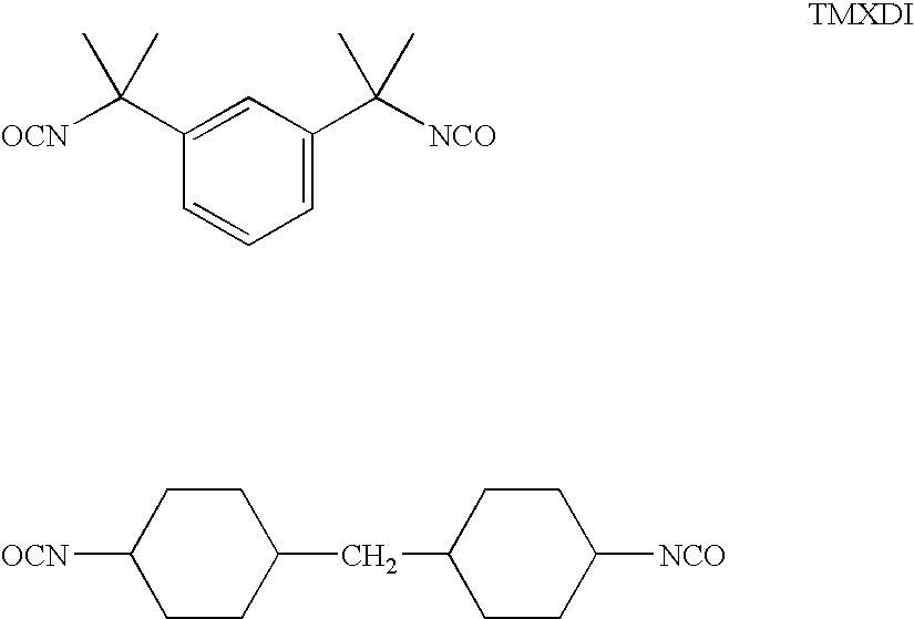
- tetramethylxylene diisocyanate (TMXDI-IUPAC name 1,3-bis(1-isocyanato-1-methylethyl)benzene) can be used for this purpose.
- TMXDI contains an aromatic ring, its two isocyanate groups are not directly attached to the aromatic ring, making it less reactive than other aromatic diisocyanates, such as toluene diisocyanate (TDI) or methylene diphenyldiisocyanate (MDI-IUPAC name bis(4-isocyanatophenyl)methane).
- TDI toluene diisocyanate
- MDI-IUPAC name bis(4-isocyanatophenyl)methane methylene diphenyldiisocyanate
- PCL poly(caprolactone)
- PPO poly(propylene oxide)
- Polyurethanes A, B and C were formulated to have the same molar ratios of diol to diisocyanate;
- Polyurethane D is a custom polyurethane prepared by a third party in accordance with U.S. Patent Publication No. 2005/0124751, while Binder E was also a commercial polyurethane.
- de-ionized water 105 g was added to convert the prepolymer to a water-borne polyurethane dispersion.
- Chain extension reaction was carried out immediately after the dispersion step with hexamethylenediamine (3.3 g, from Aldrich) dissolved in a small amount of de-ionized water over a period of 1 hour at 35° C. Finally, the dispersion was heated to 70° C. for 1 hour to ensure that all residual isocyanate groups had reacted.
- Polyurethane B was carried out under nitrogen as follows.
- a prepolymer was prepared in a three-necked round-bottomed flask equipped with a magnetic stirrer, a condenser, and a nitrogen inlet.
- dibutyltin dilaurate 0.04 g
- Polyurethane C was carried out under nitrogen as follows.
- a prepolymer was prepared in a three-necked round-bottomed flask equipped with a magnetic stirrer, a condenser, and a nitrogen inlet.
- polycaprolactone diol 31.25 g, from Aldrich, M n about 1250
- dibutyltin dilaurate 0.04 g
- Chain extension reaction was carried out immediately after the dispersion step with hexamethylenediamine (3.3 g) dissolved in a small amount of de-ionized water over a period of 1 hour at 30° C. Finally, the dispersion was heated to 70° C. for 1 hour to ensure that all residual isocyanate groups had reacted.
- electrophoretic capsules comprising an internal phase containing carbon black and titania electrophoretic particles in a hydrocarbon fluid, surrounded by a capsule wall formed from a gelatin/acacia coacervate, were prepared substantially as described in U.S. Patent Publication No. 2002/0180687, Paragraphs [0067] to [0072].
- the resultant capsules were mixed with the binders and binder blends specified below and formed into experimental single pixel displays substantially as described in Paragraphs [0073] and [0074] of this Publication, except that a backplane comprising a carbon black electrode on a polymer film was used.
- the lamination adhesive used was Binder D doped with 180 parts per million of tetrabutylammonium hexafluorophosphate (cf. the aforementioned U.S. Pat. No. 7,012,735).
- the resultant experimental displays were then tested for their dwell time dependence in both their black and white extreme optical states.
- the experimental displays could be driven between these two extreme optical states by 15 V, 500 millisecond pulses of appropriate polarity.
- Each display was first rapidly driven multiple times between its two extreme optical states to erase the effects of previous switching.
- the white state DTD (“WS DTD”) given in Table 2 below is the maximum difference between the L* values of white extreme optical states caused by variation of the period for which the display had been allowed to remain in its black extreme optical state.
- Dark state DTD (“DS DTD”) was measured in a corresponding manner.
- Binder A which is formed from PPO as its polyether, does not give good DTD performance when used alone as a binder; hence, the presence of PPO alone in a binder is not sufficient to achieve good DTD performance.
- Binder D when 25 weight per cent of Binder D was blended with Binder A, the DTD performance significantly improved. From a material point of view, this blending only introduces aromatic TMXDI moiety into the binder since the rest of the components in these two materials are exactly the same. This suggests that the use of an aromatic diisocyanate in the synthesis of the binder may be important in achieving good DTD characteristics. This view if reinforced by the fact that Binder E alone did not show good DTD performance.
- Binder C which combines an aromatic diisocyanate with polycaprolactone, was synthesized to aid in resolving this question. From Table 2, it will be seen that Binder C alone did not give good DTD performance, whereas a blend of Binder C with Binder D did give good DTD performance. This strongly suggests that the presence of both an aromatic diisocyanate and a polyether diol is required for good DTD performance.
- FIG. 2 shows substantial reduction in DTD compared with FIG. 1 ; the overall Max-Min range is reduced from 2.4 L* to 1.2 L*, and the sign of the DTD is generally opposite to that in FIG. 1 , thus implying that the electrophoretic particles were experiencing a smaller voltage than that actually applied between the electrodes.
- FIG. 1 binder and the Polyurethane D binder typically result in DTD values of opposite sign for a given capsule, rest period and pulse length. Accordingly experiments were conducted to determine whether use of a blend of the two binders would give better results than either binder alone. Accordingly, the experiments of Example 3 were repeated using the same capsules as in Example 3 for the two binders and for a 1:3 w/w mixture of the Polyurethane D binder and the prior art binder. It should be noted that both the Polyurethane D binder and the 1:3 mixture are binders of the present invention. The results, taken at 25° C. and 30 per cent relative humidity, are shown in FIGS. 3 to 8 of the accompanying drawings, where these Figures are as follows:
- FIG. 3 White state DTD, Polyurethane D binder
- FIG. 4 White state DTD, FIG. 1 binder
- FIG. 5 White state DTD, Mixture
- FIG. 6 Dark state DTD, Polyurethane D binder
- FIG. 7 Dark state DTD, FIG. 1 binder
- FIG. 8 Dark state DTD, Mixture
- FIG. 3 Range 3.3 L*
- FIG. 4 Range 4.4 L*, standard deviation 0.4 L*;
- FIG. 5 Range 0.6 L*, standard deviation 0.0 L*;
- FIG. 6 Range 1.1 L*, standard deviation 0.3 L*;
- FIG. 7 Range 6.3 L*, standard deviation 0.3 L*;
- FIG. 8 Range 1. 3 L*, standard deviation 0.1 L*.
Abstract
An electrophoretic medium comprises discrete droplets of an electrophoretic internal phase comprising a fluid and carbon black particles in the fluid. The droplets are surrounded by a polyurethane binder formed by a diisocyanate and a polyether diol, at least 20 mole per cent of the diisocyanate being an aromatic diisocyanate.
Description
- This application claims benefit of copending Application Ser. No. 60/596,836, filed Oct. 25, 2005.
- This application is related to:
-
- (a) U.S. Pat. No. 7,110,164;
- (b) U.S. Pat. No. 6,982,178;
- (c) U.S. Pat. No. 6,831,769; and
- (d) U.S. Pat. No. 7,119,772.
- The entire contents of this copending application and patents, and of all other U.S. patents and published and copending applications mentioned below, are herein incorporated by reference.
- The present invention relates to electrophoretic media and displays with an improved binder. More specifically, this invention relates to electrophoretic media and displays with a binder which reduces dwell time dependence.
- The terms “bistable” and “bistability” are used herein in their conventional meaning in the art to refer to displays comprising display elements having first and second display states differing in at least one optical property, and such that after any given element has been driven, by means of an addressing pulse of finite duration, to assume either its first or second display state, after the addressing pulse has terminated, that state will persist for at least several times, for example at least four times, the minimum duration of the addressing pulse required to change the state of the display element. It is shown in published U.S. Patent Application No. 2002/0180687 that some particle-based electrophoretic displays capable of gray scale are stable not only in their extreme black and white states but also in their intermediate gray states, and the same is true of some other types of electro-optic displays. This type of display is properly called “multi-stable” rather than bistable, although for convenience the term “bistable” may be used herein to cover both bistable and multi-stable displays.
- Particle-based electrophoretic displays have been the subject of intense research and development for a number of years. In this type of display, a plurality of charged particles move through a fluid under the influence of an electric field. Electrophoretic displays can have attributes of good brightness and contrast, wide viewing angles, state bistability, and low power consumption when compared with liquid crystal displays. Nevertheless, problems with the long-term image quality of these displays have prevented their widespread usage. For example, particles that make up electrophoretic displays tend to settle, resulting in inadequate service-life for these displays.
- As noted above, electrophoretic media require the presence of a fluid. In most prior art electrophoretic media, this fluid is a liquid, but electrophoretic media can be produced using gaseous fluids; see, for example, Kitamura, T., et al., “Electrical toner movement for electronic paper-like display”, IDW Japan, 2001, Paper HCS1-1, and Yamaguchi, Y., et al., “Toner display using insulative particles charged triboelectrically”, IDW Japan, 2001, Paper AMD4-4). See also U.S. Patent Publication No. 2005/0001810; European Patent Applications 1,462,847; 1,482,354; 1,484,635; 1,500,971; 1,501,194; 1,536,271; 1,542,067; 1,577,702; 1,577,703; and 1,598,694; and International Applications WO 2004/090626; WO 2004/079442; and WO 2004/001498. Such gas-based electrophoretic media appear to be susceptible to the same types of problems due to particle settling as liquid-based electrophoretic media, when the media are used in an orientation which permits such settling, for example in a sign where the medium is disposed in a vertical plane. Indeed, particle settling appears to be a more serious problem in gas-based electrophoretic media than in liquid-based ones, since the lower viscosity of gaseous suspending fluids as compared with liquid ones allows more rapid settling of the electrophoretic particles.
- Numerous patents and applications assigned to or in the names of the Massachusetts Institute of Technology (MIT) and E Ink Corporation have recently been published describing encapsulated electrophoretic media. Such encapsulated media comprise numerous small capsules, each of which itself comprises an internal phase containing electrophoretically-mobile particles suspended in a liquid suspending medium, and a capsule wall surrounding the internal phase. Typically, the capsules are themselves held within a polymeric binder to form a coherent layer positioned between two electrodes. Encapsulated media of this type are described, for example, in U.S. Pat. Nos. 5,930,026; 5,961,804; 6,017,584; 6,067,185; 6,118,426; 6,120,588; 6,120,839; 6,124,851; 6,130,773; 6,130,774; 6,172,798; 6,177,921; 6,232,950; 6,249,271; 6,252,564; 6,262,706; 6,262,833; 6,300,932; 6,312,304; 6,312,971; 6,323,989; 6,327,072; 6,376,828; 6,377,387; 6,392,785; 6,392,786; 6,413,790; 6,422,687; 6,445,374; 6,445,489; 6,459,418; 6,473,072; 6,480,182; 6,498,114; 6,504,524; 6,506,438; 6,512,354; 6,515,649; 6,518,949; 6,521,489; 6,531,997; 6,535,197; 6,538,801; 6,545,291; 6,580,545; 6,639,578; 6,652,075; 6,657,772; 6,664,944; 6,680,725; 6,683,333; 6,704,133; 6,710,540; 6,721,083; 6,724,519; 6,727,881; 6,738,050; 6,750,473; 6,753,999; 6,816,147; 6,819,471; 6,822,782; 6,825,068; 6,825,829; 6,825,970; 6,831,769; 6,839,158; 6,842,167; 6,842,279; 6,842,657; 6,864,875; 6,865,010; 6,866,760; 6,870,661; 6,900,851; 6,922,276; 6,950,200; 6,958,848; 6,967,640; 6,982,178; 6,987,603; 6,995,550; 7,002,728; 7,012,600; 7,012,735; 7,023,430; 7,030,412; 7,030,854; 7,034,783; 7,038,655; 7,061,663; 7,071,913; 7,075,502; 7,075,703; 7,079,305; 7,106,296; 7,109,968; 7,110,163; 7,110,164; 7,116,318; 7,116,466; 7,119,759; and 7,119,772; and U.S. Patent Applications Publication Nos. 2002/0060321; 2002/0090980; 2002/0180687; 2003/0011560; 2003/0102858; 2003/0151702; 2003/0222315; 2004/0014265; 2004/0075634; 2004/0094422; 2004/0105036; 2004/0112750; 2004/0119681; 2004/0136048; 2004/0155857; 2004/0180476; 2004/0190114; 2004/0196215; 2004/0226820; 2004/0239614; 2004/0257635; 2004/0263947; 2005/0000813; 2005/0007336; 2005/0012980; 2005/0017944; 2005/0018273; 2005/0024353; 2005/0062714; 2005/0067656; 2005/0078099; 2005/0099672; 2005/0122284; 2005/0122306; 2005/0122563; 2005/0122565; 2005/0134554; 2005/0146774; 2005/0151709; 2005/0152018; 2005/0152022; 2005/0156340; 2005/0168799; 2005/0179642; 2005/0190137; 2005/0212747; 2005/0213191; 2005/0219184; 2005/0253777; 2005/0270261; 2005/0280626; 2006/0007527; 2006/0024437; 2006/0038772; 2006/0139308; 2006/0139310; 2006/0139311; 2006/0176267; 2006/0181492; 2006/0181504; 2006/0194619; 2006/0197736; 2006/0197737; 2006/0197738; 2006/0198014; 2006/0202949; and 2006/0209388; and International Applications Publication Nos. WO 00/38000; WO 00/36560; WO 00/67110; and WO 01/07961; and European Patents Nos. 1,099,207 B1; and 1,145,072 B1.
- Many of the aforementioned patents and applications recognize that the walls surrounding the discrete microcapsules in an encapsulated electrophoretic medium could be replaced by a continuous phase, thus producing a so-called polymer-dispersed electrophoretic display, in which the electrophoretic medium comprises a plurality of discrete droplets of an electrophoretic fluid and a continuous phase of a polymeric material, and that the discrete droplets of electrophoretic fluid within such a polymer-dispersed electrophoretic display may be regarded as capsules or microcapsules even though no discrete capsule membrane is associated with each individual droplet; see for example, the aforementioned U.S. Pat. No. 6,866,760. Accordingly, for purposes of the present application, such polymer-dispersed electrophoretic media are regarded as sub-species of encapsulated electrophoretic media.
- A related type of electrophoretic display is a so-called “microcell electrophoretic display”. In a microcell electrophoretic display, the charged particles and the suspending fluid are not encapsulated within microcapsules but instead are retained within a plurality of cavities formed within a carrier medium, typically a polymeric film. See, for example, International Application Publication No. WO 02/01281, and published US Application No. 2002/0075556, both assigned to Sipix Imaging, Inc.
- Although electrophoretic media are often opaque (since, for example, in many electrophoretic media, the particles substantially block transmission of visible light through the display) and operate in a reflective mode, many electrophoretic displays can be made to operate in a so-called “shutter mode” in which one display state is substantially opaque and one is light-transmissive. See, for example, the aforementioned U.S. Pat. Nos. 6,130,774 and 6,172,798, and U.S. Pat. Nos. 5,872,552; 6,144,361; 6,271,823; 6,225,971; and 6,184,856. Dielectrophoretic displays, which are similar to electrophoretic displays but rely upon variations in electric field strength, can operate in a similar mode; see U.S. Pat. No. 4,418,346.
- An encapsulated electrophoretic display typically does not suffer from the clustering and settling failure mode of traditional electrophoretic devices and provides further advantages, such as the ability to print or coat the display on a wide variety of flexible and rigid substrates. (Use of the word “printing” is intended to include all forms of printing and coating, including, but without limitation: pre-metered coatings such as patch die coating, slot or extrusion coating, slide or cascade coating, curtain coating; roll coating such as knife over roll coating, forward and reverse roll coating; gravure coating; dip coating; spray coating; meniscus coating; spin coating; brush coating; air knife coating; silk screen printing processes; electrostatic printing processes; thermal printing processes; ink jet printing processes; and other similar techniques.) Thus, the resulting display can be flexible. Further, because the display medium can be printed (using a variety of methods), the display itself can be made inexpensively.
- As already noted, an encapsulated electrophoretic medium typically comprises electrophoretic capsules disposed in a polymeric binder, which serves to form the discrete capsules into a coherent layer. The continuous phase in a polymer-dispersed electrophoretic medium, and the cell walls of a microcell medium serve similar functions. It has been found by E Ink researchers that the specific material used as the binder in an electrophoretic medium can affect the electro-optic properties of the medium. Among the electro-optic properties of an electrophoretic medium affected by the choice of binder is the so-called “dwell time dependence”. As discussed in the aforementioned U.S. Pat. No. 7,119,772 (see especially
FIG. 34 and the related description). It has been found that, at least in some cases, the impulse necessary for a transition between two specific optical states of a bistable electrophoretic display varies with the residence time of a pixel in its initial optical state, and this phenomenon is referred to as “dwell time dependence” or “DTD”. Obviously, it is desirable to keep DTD as small as possible since DTD affects the difficulty of driving the display and may affect the quality of the image produced; for example, DTD may cause pixels which are supposed to form an area of uniform gray color to differ slightly from one another in gray level, and the human eye is very sensitive to such variations. Although it has been known that the choice of binder affects DTD, choosing an appropriate binder for any specific electrophoretic medium has hitherto been based on trial-and-error, with essentially no understanding of the relationship between DTD and the chemical nature of the binder. - It is known (see for example, copending application Ser. No. 11/428,584, filed Jul. 5, 2006) that various physico-chemical properties, especially the electrical properties, of the binder used in electrophoretic displays can have a significant effect on the electro-optic performance of such displays. Choosing a binder which satisfies all the relevant requirements for use in such displays is not easy, and in practice only a limited number of commercial materials are suitable. Typically, in practice a polyurethane resin, normally supplied as an aqueous latex, is used to form the binder. It has now been discovered that, for certain types of electrophoretic media, DTD is strongly influenced by the aromatic content of a polyurethane binder, and this invention provides electrophoretic media with polyurethane binders and low DTD.
- This invention provides an electrophoretic medium comprising a plurality of discrete droplets of an electrophoretic internal phase, the internal phase comprising a fluid and carbon black particles in the fluid, the droplets being surrounded by a polyurethane binder formed by a diisocyanate and a polyether diol, wherein at least about 20 mole per cent of the diisocyanate is an aromatic diisocyanate. Desirably at least about 50 mole per cent, and preferably at least about 75 mole per cent, of the diisocyanate is an aromatic diisocyanate. The internal phase used in the electrophoretic medium of the invention may comprise only carbon black particles in a colored fluid, but preferably the electrophoretic medium is of the dual particle type having a second type of electrophoretic particle (in addition to carbon black) in the fluid, the second type of electrophoretic particles differing from the carbon black particles in at least one optical characteristic, and in electrophoretic mobility. For example, in one preferred form of the present invention the electrophoretic medium contains carbon black particles and white titania particles bearing a charge of opposite polarity to the carbon black particles.
- The polyurethane binder used in the display of the present invention may comprise a single polyurethane formed from an aromatic diisocyanate and a polyether diol. Alternatively, the binder used may comprise a blend of two or more polyurethanes, at least one of which is formed from an aromatic diisocyanate and a polyether diol. For example, the binder may comprise a first polyurethane formed from an aromatic diisocyanate and a polyether diol, and a second polyurethane formed from an aliphatic diisocyanate and a polyester diol. A preferred polyether diol for use in the polyurethane binder is poly(propylene glycol), desirably one having a molecular weight of about 1500 to about 5000.
- The electrophoretic medium of the present invention may be an encapsulated electrophoretic medium having a capsule wall interposed between each droplet and the binder. The electrophoretic medium may also be of the polymer-dispersed type with the droplets of internal phase dispersed directly (without any intervening capsule wall) in a continuous phase of the binder. Finally, the electrophoretic medium of the present invention may be of the microcell type, with the binder forming the walls of a plurality of closed cavities within which the internal phase is retained.
- This invention also provides an electrophoretic medium comprising a plurality of discrete droplets of an electrophoretic internal phase, the internal phase comprising a fluid and carbon black particles in the fluid, the droplets being surrounded by a polyurethane binder formed by a diisocyanate and a polyether diol, wherein at least about 20 mole per cent of the diisocyanate comprises TMXDI (see below for the formal name of this diisocyanate. In such a medium, at least about 50 mole per cent of the diisocyanate may comprises TMXDI; indeed, the diisocyanate may consist essentially of TMXDI.
- This invention extends to an electrophoretic display comprising an electrophoretic medium of the invention in combination with at least one electrode disposed adjacent the electrophoretic medium and arranged to apply an electric field thereto.
-
FIG. 1 of the accompanying drawings is a graph showing the variation of dwell time dependence of the white state of a prior art electrophoretic binder against pulse length and rest period, as obtained in certain experiments described below. -
FIG. 2 is a graph similar toFIG. 1 but showing the results obtained with a binder of the present invention, as described in Example 3 below. - FIGS. 3 to 5 are graphs similar to those of
FIGS. 1 and 2 but showing the results obtained with a prior art binder, a simple binder of the present invention and a mixed binder of the present invention respectively. - FIGS. 6 to 8 are graphs similar to those of FIGS. 3 to 5 respectively but showing the corresponding dark state dwell time dependencies.
- As already mentioned, the present invention relates to an electrophoretic medium comprising carbon black electrophoretic particles and a polyurethane binder. At least part of the binder is formed from an aromatic diisocyanate and a polyether diol. It should be noted that the present invention appears to be specific to electrophoretic media containing carbon black (although similar results may be obtained from electrophoretic media containing other electrically-conductive electrophoretic particles, for example metals); similar results are not obtained from electrophoretic media in which the carbon black is replaced by a non-conductive particle, for example copper chromite.
- As discussed in several of the aforementioned E Ink and MIT patents and published applications (see especially U.S. Pat. No. 7,012,600) in order to achieve accurate gray levels in an electrophoretic display, it is necessary that the correct impulse (the integral of voltage with respect to time) be delivered to a pixel to place the electrophoretic particles in the correct positions to generate the desired optical state. In electrophoretic displays where the internal phase (electrophoretic particles and surrounding fluid) is in direct contact with the electrodes, this is simple. However, in encapsulated media (whether of the capsule-based, polymer-dispersed or microcell types), there is an ionic conducting polymeric external phase (capsule wall and/or binder) in between the internal phase and the electrodes, and hence a complex charge screening layer is formed that can affect the field actually experienced by the electrophoretic particles. Moreover, the charge screening layer will decay over time after the applied voltage has been removed. This residual charge screening layer adds a real voltage to subsequent addressing pulses that will vary the electric field experienced by the electrophoretic particles, hence delivering an incorrect impulse to the electrophoretic particles. The macroscopic effect of this inadvertent “distortion” of the applied electric field is that a spatially correlated afterimage can appear in a subsequent image updates, and the severity of this afterimage correlates to the time since the last image update.
- It has been discovered that the major factor affecting the amount of DTD seen in an electrophoretic display is the type of binder used. It is known (see for example the aforementioned U.S. Pat. No. 6,831,769) that a blend of two latex polyurethanes can be used as a binder in an encapsulated electrophoretic medium. The DTD of such a medium can be measured by observing a reference optical state (for a given pulse length) when the sample is switched after resting for a long period (say 30 seconds) with in its previous optical state. This reference state is compared to the optical state obtained when a shorter rest period (typically 0.4 to 10 second) is used. In order to allow for the effects of electrophoretic medium switching speed and medium thickness, this DTD measurement is repeated for multiple pulse lengths and the results are plotted as a three dimensional graph of optical difference against pulse length and rest period.
FIG. 1 of the accompanying drawing shows such a graph of the white state DTD for a laboratory scale sample using a conventional mixed polyurethane latex binder. It will be appreciated that DTD can be different for white-to-black and black-to-white transitions; “white state DTD” refers to the effect of a final white state of varying rest periods in a previous black or gray state.) - The absolute values in the graph depend on the reference state, and thus are less important than the full range of optical states resulting from changes in rest period and pulse length. Accordingly, the most convenient parameter to characterize DTD is Maximum-Minimum range of these measurements, which in
FIG. 1 is 2.4 L* units. Another important characteristic is the shape of the curve: inFIG. 1 , the maximum DTD occurs at short pulse lengths and short rest periods, and the effect of DTD is to increase the optical state for the white state. This implies that the electrophoretic particles are experiencing a larger voltage when switched under these conditions. - The effects of changes in the binder composition are illustrated in the Examples below.
- It is now necessary to consider the effect of polyurethane chemistry in the present invention. As is well known to those skilled in polyurethane technology, a diisocyanate is a compound containing two —N═C═O (NCO) groups. A urethane linkage is formed when an isocyanate group reacts with a hydroxyl group. The polyaddition reaction between a diisocyanate and a diol (a compound containing two hydroxyl groups) is the basic reaction to produce a polyurethane. Because some isocyanates react with water, only less reactive aliphatic diisocyanates are commonly used in the synthesis of water-borne polyurethane dispersions (latices); however, tetramethylxylene diisocyanate (TMXDI-IUPAC name 1,3-bis(1-isocyanato-1-methylethyl)benzene) can be used for this purpose. Although TMXDI contains an aromatic ring, its two isocyanate groups are not directly attached to the aromatic ring, making it less reactive than other aromatic diisocyanates, such as toluene diisocyanate (TDI) or methylene diphenyldiisocyanate (MDI-IUPAC name bis(4-isocyanatophenyl)methane). The experiments below illustrate properties of water-borne polyurethane binders made from an aliphatic diisocyanate and aromatic TMXDI with either poly(caprolactone) (PCL) or poly(propylene oxide) (PPO) as the other reactant. The experimental results demonstrate that the presence of both an aromatic diisocyanate and a polyether is necessary to achieve good DTD performance in an electrophoretic medium containing carbon black electrophoretic particles.
- The reactants used in the experiments were as follows:
- H12MDI (IUPAC name bis(4-isocyanatocyclohexyl)methane)

- Five different polyurethanes were used in these experiments, as set out In Table 1 below:
TABLE 1 Poly- Solids, urethane Diisocyanate Diol Mw pH wt. % A H12MDI PPO 64100 7.7 40 B TMXDI PPO 38700 8.4 40 C TMXDI PCL 29700 7.6 34 D TMXDI PPO 45000-55000 7.5-8.5 35 E H12MDI Polyester 100-200K 7.5-8.5 40 - Polyurethanes A, B and C were formulated to have the same molar ratios of diol to diisocyanate; Polyurethane D is a custom polyurethane prepared by a third party in accordance with U.S. Patent Publication No. 2005/0124751, while Binder E was also a commercial polyurethane.
- The synthesis of Polyurethane A was carried out under nitrogen as follows. A jacketed 500 mL glass reactor was equipped with a mechanical stirrer, a thermometer, and a nitrogen inlet. H12MDI (20.99 g of Bayer Desmodur W, 0.08 mole), poly(propylene glycol) diol (50 g, supplied by Aldrich Chemical Company, Mn about 2000), and dibutyltin dilaurate (0.04 g, from Aldrich) were charged into the reactor and the mixture was heated at 90° C. for 2 hours. (Unless otherwise stated, in all the reactions below the reagents used are the same as those used in the synthesis of Polyurethane A.) A solution of 2,2-bis(hydroxymethyl)propionic acid (3.35 g, from Aldrich) in 1-methyl-2-pyrrolidinone (10 g, from Aldrich) was then added and the reaction allowed to proceed at 90° C. for another hour to produce an NCO-terminated prepolymer. The reactor temperature was then lowered to 70° C., and triethylamine (2.4 g, from Aldrich) was added; the resultant mixture was allowed to stand at this temperature for 30 minutes to neutralize carboxylic acid. The reactor temperature was then further lowered to 35° C. and de-ionized water (105 g) was added to convert the prepolymer to a water-borne polyurethane dispersion. Chain extension reaction was carried out immediately after the dispersion step with hexamethylenediamine (3.3 g, from Aldrich) dissolved in a small amount of de-ionized water over a period of 1 hour at 35° C. Finally, the dispersion was heated to 70° C. for 1 hour to ensure that all residual isocyanate groups had reacted.
- The synthesis of Polyurethane B was carried out under nitrogen as follows. A prepolymer was prepared in a three-necked round-bottomed flask equipped with a magnetic stirrer, a condenser, and a nitrogen inlet. TMXDI (19.54 g, from Aldrich, 0.08 mole), poly(propylene glycol) diol (50 g), and dibutyltin dilaurate (0.04 g) were charged into the flask and the mixture was heated in a silicon oil bath on a hotplate at 90° C. for 2 hours. A solution of 2,2-bis(hydroxymethyl)propionic acid (3.35 g) in 1-methyl-2-pyrrolidinone (10 g) was then added and the reaction allowed to proceed at 90° C. for another hour to produce an NCO-terminated prepolymer. The reactor temperature was then lowered to 70° C., and triethylamine (2.4 g) was added; the resultant mixture was allowed to stand at this temperature for 30 minutes to neutralize carboxylic acid. At this point, dibutylamine (0.388 g, from Aldrich, 5 mole per cent relative to the residual NCO groups) was added as a chain stopper. The resultant reaction mixture was slowly added to de-ionized water (105 g) at 35° C. in a jacketed 500 mL glass reactor under mechanical stirring and a nitrogen atmosphere. Chain extension reaction was carried out immediately after the dispersion step with hexamethylenediamine (3.3 g) dissolved in a small amount of de-ionized water over a period of 1 hour at 35° C. Finally, the dispersion was heated to 70° C. for 1 hour to ensure that all residual isocyanate groups had reacted.
- The synthesis of Polyurethane C was carried out under nitrogen as follows. A prepolymer was prepared in a three-necked round-bottomed flask equipped with a magnetic stirrer, a condenser, and a nitrogen inlet. TMXDI (19.54 g, 0.08 mole), polycaprolactone diol (31.25 g, from Aldrich, Mn about 1250), and dibutyltin dilaurate (0.04 g) were charged into the flask and the mixture was heated in a silicon oil bath on a hotplate at 80° C. for 2 hours. A solution of 2,2-bis(hydroxymethyl)propionic acid (3.35 g) in 1-methyl-2-pyrrolidinone (10 g) was then added and the reaction allowed to proceed at 80° C. for another hour to produce an NCO-terminated prepolymer. The reactor temperature was then lowered to 60° C., and triethylamine (2.4 g) was added; the resultant mixture was allowed to stand at this temperature for 30 minutes to neutralize carboxylic acid. The resultant reaction mixture was slowly added to de-ionized water (105 g) at 30° C. in a jacketed 500 mL glass reactor under mechanical stirring and a nitrogen atmosphere. Chain extension reaction was carried out immediately after the dispersion step with hexamethylenediamine (3.3 g) dissolved in a small amount of de-ionized water over a period of 1 hour at 30° C. Finally, the dispersion was heated to 70° C. for 1 hour to ensure that all residual isocyanate groups had reacted.
- When water was added to TMXDI-based prepolymers, the formation of some large particles was observed. It was found that formation of such large particles could be avoided by adding the prepolymer to water, as described in the preparation of Polyurethanes B and C above. This problem did not occur with H12MDI-based prepolymers.
- In order to evaluate the effect of the various polyurethane binders on the electro-optic properties of electrophoretic displays, electrophoretic capsules comprising an internal phase containing carbon black and titania electrophoretic particles in a hydrocarbon fluid, surrounded by a capsule wall formed from a gelatin/acacia coacervate, were prepared substantially as described in U.S. Patent Publication No. 2002/0180687, Paragraphs [0067] to [0072]. The resultant capsules were mixed with the binders and binder blends specified below and formed into experimental single pixel displays substantially as described in Paragraphs [0073] and [0074] of this Publication, except that a backplane comprising a carbon black electrode on a polymer film was used. The lamination adhesive used was Binder D doped with 180 parts per million of tetrabutylammonium hexafluorophosphate (cf. the aforementioned U.S. Pat. No. 7,012,735).
- The resultant experimental displays were then tested for their dwell time dependence in both their black and white extreme optical states. The experimental displays could be driven between these two extreme optical states by 15 V, 500 millisecond pulses of appropriate polarity. Each display was first rapidly driven multiple times between its two extreme optical states to erase the effects of previous switching. To evaluate white state DTD, each display was then driven to its black extreme optical state, allowed to remain in this state for a period varying from zero to several minutes, and then switched to its white extreme optical state, and its reflectivity measured, and the measured reflectivity converted to standard L* units ((where L* has the usual CIE definition:
L*=116(R/R 0)1/3−16, - where R is the reflectance and R0 is a standard reflectance value). The white state DTD (“WS DTD”) given in Table 2 below is the maximum difference between the L* values of white extreme optical states caused by variation of the period for which the display had been allowed to remain in its black extreme optical state. Dark state DTD (“DS DTD”) was measured in a corresponding manner. The results obtained are shown in Table 2 below:
TABLE 2 Binder WS DTD L* DS DTD L* A >6 L* >4 L* A/D (w/w = 3/1) <2 L* <2 L* E >4 L* >4 L* E/D (w/w = 3/1) <2 L* <2 L* E/B (w/w = 3/1) <2 L* <2 L* C >8 L* >4 L* C/D (w/w = 3/1) <2 L* <2 L* E/C (w/w = 3/1) >6 L* >4 L* - From Table 2, it will be seen that Binder A, which is formed from PPO as its polyether, does not give good DTD performance when used alone as a binder; hence, the presence of PPO alone in a binder is not sufficient to achieve good DTD performance. However, when 25 weight per cent of Binder D was blended with Binder A, the DTD performance significantly improved. From a material point of view, this blending only introduces aromatic TMXDI moiety into the binder since the rest of the components in these two materials are exactly the same. This suggests that the use of an aromatic diisocyanate in the synthesis of the binder may be important in achieving good DTD characteristics. This view if reinforced by the fact that Binder E alone did not show good DTD performance. However, from Table 2 it will be seen that the DTD performance of Binder E improved when it is blended with either Binder B or D, both of which were produced from the aromatic diisocyanate TMXDI and the polyether diol PPO. Thus, the results in Table 2 strongly suggest that to achieve good DTD performance with the carbon black/titania electrophoretic medium used, it is necessary to use a polyurethane binder containing an aromatic diisocyanate.
- It is still necessary to decide whether the presence of an aromatic diisocyanate alone is sufficient for good DTD performance or whether such good performance requires both an aromatic diisocyanate and a polyether diol, and Binder C, which combines an aromatic diisocyanate with polycaprolactone, was synthesized to aid in resolving this question. From Table 2, it will be seen that Binder C alone did not give good DTD performance, whereas a blend of Binder C with Binder D did give good DTD performance. This strongly suggests that the presence of both an aromatic diisocyanate and a polyether diol is required for good DTD performance. The correctness of this deduction is confirmed by the fact that a blend of Binders C and E (both of which use a polyester diol) does not give good DTD performance. It should be noted that the improved DTD performance exhibited by a polyurethane formed from an aromatic diisocyanate and a polyether diol cannot be attributed simply to a change in the volume resistivity of the polyurethane, since all the binders used in the experiments described above had volume resistivities of the same order of magnitude.
- The experiments used to generate the graph shown in
FIG. 1 were repeated with the same capsules but using as the binder Polyurethane D from Table 1 above. The results are shown inFIG. 2 . -
FIG. 2 shows substantial reduction in DTD compared withFIG. 1 ; the overall Max-Min range is reduced from 2.4 L* to 1.2 L*, and the sign of the DTD is generally opposite to that inFIG. 1 , thus implying that the electrophoretic particles were experiencing a smaller voltage than that actually applied between the electrodes. - The experiments which produced the graphs of
FIGS. 1 and 2 were repeated several times using the same binders but different types of capsules. Although the values of the DTD range varied considerably with the specific type of capsules used (varying from 3.4 to 7.2 L* units for theFIG. 1 binder and from 0.6 to 4.7 L* for Polyurethane D), in every case the Polyurethane D binder showed a lower DTD range than theFIG. 1 binder. - As noted above, the
FIG. 1 binder and the Polyurethane D binder typically result in DTD values of opposite sign for a given capsule, rest period and pulse length. Accordingly experiments were conducted to determine whether use of a blend of the two binders would give better results than either binder alone. Accordingly, the experiments of Example 3 were repeated using the same capsules as in Example 3 for the two binders and for a 1:3 w/w mixture of the Polyurethane D binder and the prior art binder. It should be noted that both the Polyurethane D binder and the 1:3 mixture are binders of the present invention. The results, taken at 25° C. and 30 per cent relative humidity, are shown in FIGS. 3 to 8 of the accompanying drawings, where these Figures are as follows: -
FIG. 3 : White state DTD, Polyurethane D binder; -
FIG. 4 : White state DTD,FIG. 1 binder; -
FIG. 5 : White state DTD, Mixture; -
FIG. 6 : Dark state DTD, Polyurethane D binder; -
FIG. 7 : Dark state DTD,FIG. 1 binder; and -
FIG. 8 : Dark state DTD, Mixture; - From FIGS. 3 to 8 it will be seen that the blend showed reduced DTD in the white state and substantially the same DTD as Polyurethane D in the dark state; in both states, the blend was much superior to the
FIG. 1 binder. The actual values were as follows: -
FIG. 3 : Range 3.3 L*; -
FIG. 4 : Range 4.4 L*, standard deviation 0.4 L*; -
FIG. 5 : Range 0.6 L*, standard deviation 0.0 L*; -
FIG. 6 : Range 1.1 L*, standard deviation 0.3 L*; -
FIG. 7 : Range 6.3 L*, standard deviation 0.3 L*; and -
FIG. 8 : Range 1. 3 L*, standard deviation 0.1 L*. - The foregoing experiments show that the presence of aromatic diisocyanate residues (such as TMXDI residues) along with polyether diol residues (for example PPO residues) in a polyurethane binder offers a beneficial reduction in dwell time dependency in encapsulated electrophoretic displays containing carbon black electrophoretic particles. A low DTD is highly desirable in electrophoretic displays to permit accurate and consistent rendition of gray scale images despite arbitrary differences in the times between changes in displayed images.
- Numerous changes and modifications can be made in the preferred embodiments of the present invention already described without departing from the scope of the invention. Accordingly, the foregoing description is to be construed in an illustrative and not in a limitative sense.
Claims (20)
1. An electrophoretic medium comprising a plurality of discrete droplets of an electrophoretic internal phase, the internal phase comprising a fluid and carbon black particles in the fluid, the droplets being surrounded by a polyurethane binder formed by a diisocyanate and a polyether diol, wherein at least about 20 mole per cent of the diisocyanate is an aromatic diisocyanate.
2. An electrophoretic medium according to claim 1 wherein at least about 50 mole per cent of the diisocyanate is an aromatic diisocyanate.
3. An electrophoretic medium according to claim 2 wherein at least about 75 mole per cent of the diisocyanate is an aromatic diisocyanate.
4. An electrophoretic medium according to claim 1 wherein the internal phase comprises carbon black particles in a colored fluid.
5. An electrophoretic medium according to claim 1 wherein the internal phase comprises carbon black particles and a second type of electrophoretic particles differing from the carbon black particles in at least one optical characteristic and in electrophoretic mobility.
6. An electrophoretic medium according to claim 5 wherein the second type of electrophoretic particles comprise titania particles bearing a charge of opposite polarity to that on the carbon black particles.
7. An electrophoretic medium according to claim 1 wherein the polyurethane binder consists of a single polyurethane formed from an aromatic diisocyanate and a polyether diol.
8. An electrophoretic medium according to claim 1 wherein the polyurethane binder comprises a blend of at least two polyurethanes, at least one of which is formed from an aromatic diisocyanate and a polyether diol.
9. An electrophoretic medium according to claim 8 wherein the polyurethane binder comprises a first polyurethane formed from an aromatic diisocyanate and a polyether diol, and a second polyurethane formed from an aliphatic diisocyanate and a polyester diol.
10. An electrophoretic medium according to claim 9 wherein the polyether diol comprises poly(propylene glycol).
11. An electrophoretic medium according to claim 10 wherein the poly(propylene glycol) has a molecular weight of about 1500 to about 5000.
12. An electrophoretic medium according to claim 1 which is an encapsulated electrophoretic medium having a capsule wall interposed between each droplet and the binder.
13. An electrophoretic medium according to claim 1 which is of the polymer-dispersed type with the droplets of internal phase dispersed directly in a continuous phase of the binder.
14. An electrophoretic medium according to claim 1 which is of the microcell type, with the binder forming the walls of a plurality of closed cavities within which the internal phase is retained.
15. An electrophoretic medium according to claim 1 wherein the aromatic diisocyanate comprises TMXDI.
16. An electrophoretic display comprising an electrophoretic medium according to claim 1 in combination with at least one electrode disposed adjacent the electrophoretic medium and arranged to apply an electric field thereto.
17. An electrophoretic medium comprising a plurality of discrete droplets of an electrophoretic internal phase, the internal phase comprising a fluid and carbon black particles in the fluid, the droplets being surrounded by a polyurethane binder formed by a diisocyanate and a polyether diol, wherein at least about 20 mole per cent of the diisocyanate comprises TMXDI.
18. An electrophoretic medium according to claim 17 wherein at least about 50 mole per cent of the diisocyanate comprises TMXDI.
19. An electrophoretic medium according to claim 17 wherein the diisocyanate consists essentially of TMXDI.
20. An electrophoretic display comprising an electrophoretic medium according to claim 17 in combination with at least one electrode disposed adjacent the electrophoretic medium and arranged to apply an electric field thereto.
Priority Applications (1)
| Application Number | Priority Date | Filing Date | Title |
|---|---|---|---|
| US11/552,210 US20070091417A1 (en) | 2005-10-25 | 2006-10-24 | Electrophoretic media and displays with improved binder |
Applications Claiming Priority (2)
| Application Number | Priority Date | Filing Date | Title |
|---|---|---|---|
| US59683605P | 2005-10-25 | 2005-10-25 | |
| US11/552,210 US20070091417A1 (en) | 2005-10-25 | 2006-10-24 | Electrophoretic media and displays with improved binder |
Publications (1)
| Publication Number | Publication Date |
|---|---|
| US20070091417A1 true US20070091417A1 (en) | 2007-04-26 |
Family
ID=37968525
Family Applications (1)
| Application Number | Title | Priority Date | Filing Date |
|---|---|---|---|
| US11/552,210 Abandoned US20070091417A1 (en) | 2005-10-25 | 2006-10-24 | Electrophoretic media and displays with improved binder |
Country Status (2)
| Country | Link |
|---|---|
| US (1) | US20070091417A1 (en) |
| WO (1) | WO2007050686A2 (en) |
Cited By (60)
| Publication number | Priority date | Publication date | Assignee | Title |
|---|---|---|---|---|
| US20070153361A1 (en) * | 2002-06-10 | 2007-07-05 | E Ink Corporation | Components and testing methods for use in the production of electro-optic displays |
| US20070211331A1 (en) * | 2006-03-08 | 2007-09-13 | E Ink Corporation | Electro-optic displays, and materials and methods for production thereof |
| US20070223079A1 (en) * | 2006-03-22 | 2007-09-27 | E Ink Corporation | Electro-optic media produced using ink jet printing |
| US20070286975A1 (en) * | 2003-11-05 | 2007-12-13 | E Ink Corporation | Electro-optic displays, and materials for use therein |
| US20080013156A1 (en) * | 2006-07-13 | 2008-01-17 | E Ink Corporation | Particles for use in electrophoretic displays |
| US20080013155A1 (en) * | 2006-07-11 | 2008-01-17 | E Ink Corporation | Electrophoretic medium and display with improved image stability |
| US20080023332A1 (en) * | 2003-03-25 | 2008-01-31 | E Ink Corporation | Processes for the production of electrophoretic displays |
| US20080024429A1 (en) * | 2006-07-25 | 2008-01-31 | E Ink Corporation | Electrophoretic displays using gaseous fluids |
| US20080129667A1 (en) * | 2004-03-31 | 2008-06-05 | E Ink Corporation | Methods for driving electro-optic displays |
| US20080137176A1 (en) * | 2006-12-07 | 2008-06-12 | E Ink Corporation | Components and methods for use in electro-optic displays |
| US20080174853A1 (en) * | 2007-01-22 | 2008-07-24 | E Ink Corporation | Multi-layer sheet for use in electro-optic displays |
| US20080218839A1 (en) * | 2003-11-05 | 2008-09-11 | E Ink Corporation | Electro-optic displays, and materials for use therein |
| US20080254272A1 (en) * | 2007-01-22 | 2008-10-16 | E Ink Corporation | Multi-layer sheet for use in electro-optic displays |
| US20080291129A1 (en) * | 2007-05-21 | 2008-11-27 | E Ink Corporation | Methods for driving video electro-optic displays |
| US20080316582A1 (en) * | 2006-03-08 | 2008-12-25 | E Ink Corporation | Electro-optic displays, and materials and methods for production thereof |
| US20090004442A1 (en) * | 2007-06-28 | 2009-01-01 | E Ink Corporation | Processes for the production of electro-optic displays, and color filters for use therein |
| US20090109519A1 (en) * | 2007-03-06 | 2009-04-30 | E Ink Corporation | Materials for use in electrophoretic displays |
| US7649674B2 (en) | 2002-06-10 | 2010-01-19 | E Ink Corporation | Electro-optic display with edge seal |
| US7679814B2 (en) | 2001-04-02 | 2010-03-16 | E Ink Corporation | Materials for use in electrophoretic displays |
| US20100225995A1 (en) * | 2009-03-03 | 2010-09-09 | E Ink Corporation | Electro-optic displays, and color filters for use therein |
| US20100265239A1 (en) * | 2002-04-24 | 2010-10-21 | E Ink Corporation | Processes for forming backplanes for electro-optic displays |
| US20100289736A1 (en) * | 2009-02-09 | 2010-11-18 | E Ink Corporation | Electrophoretic particles, and processes for the production thereof |
| US7848006B2 (en) | 1995-07-20 | 2010-12-07 | E Ink Corporation | Electrophoretic displays with controlled amounts of pigment |
| US7999787B2 (en) | 1995-07-20 | 2011-08-16 | E Ink Corporation | Methods for driving electrophoretic displays using dielectrophoretic forces |
| US8034209B2 (en) | 2007-06-29 | 2011-10-11 | E Ink Corporation | Electro-optic displays, and materials and methods for production thereof |
| US8040594B2 (en) | 1997-08-28 | 2011-10-18 | E Ink Corporation | Multi-color electrophoretic displays |
| US8049947B2 (en) | 2002-06-10 | 2011-11-01 | E Ink Corporation | Components and methods for use in electro-optic displays |
| US8054526B2 (en) | 2008-03-21 | 2011-11-08 | E Ink Corporation | Electro-optic displays, and color filters for use therein |
| US8305341B2 (en) | 1995-07-20 | 2012-11-06 | E Ink Corporation | Dielectrophoretic displays |
| US8314784B2 (en) | 2008-04-11 | 2012-11-20 | E Ink Corporation | Methods for driving electro-optic displays |
| US8363299B2 (en) | 2002-06-10 | 2013-01-29 | E Ink Corporation | Electro-optic displays, and processes for the production thereof |
| EP2555182A1 (en) | 2007-02-02 | 2013-02-06 | E Ink Corporation | Electrophoretic displays having transparent electrode and conductor connected thereto |
| US8390301B2 (en) | 2006-03-08 | 2013-03-05 | E Ink Corporation | Electro-optic displays, and materials and methods for production thereof |
| US8390918B2 (en) | 2001-04-02 | 2013-03-05 | E Ink Corporation | Electrophoretic displays with controlled amounts of pigment |
| US8446664B2 (en) | 2010-04-02 | 2013-05-21 | E Ink Corporation | Electrophoretic media, and materials for use therein |
| US8553012B2 (en) | 2001-03-13 | 2013-10-08 | E Ink Corporation | Apparatus for displaying drawings |
| US8610988B2 (en) | 2006-03-09 | 2013-12-17 | E Ink Corporation | Electro-optic display with edge seal |
| US8654436B1 (en) | 2009-10-30 | 2014-02-18 | E Ink Corporation | Particles for use in electrophoretic displays |
| US8902153B2 (en) | 2007-08-03 | 2014-12-02 | E Ink Corporation | Electro-optic displays, and processes for their production |
| US9075280B2 (en) | 2002-09-03 | 2015-07-07 | E Ink Corporation | Components and methods for use in electro-optic displays |
| US9293511B2 (en) | 1998-07-08 | 2016-03-22 | E Ink Corporation | Methods for achieving improved color in microencapsulated electrophoretic devices |
| US9506243B1 (en) | 2014-03-20 | 2016-11-29 | E Ink Corporation | Thermally-responsive film |
| US9529240B2 (en) | 2014-01-17 | 2016-12-27 | E Ink Corporation | Controlled polymeric material conductivity for use in a two-phase electrode layer |
| US9664978B2 (en) | 2002-10-16 | 2017-05-30 | E Ink Corporation | Electrophoretic displays |
| US9964831B2 (en) | 2007-11-14 | 2018-05-08 | E Ink Corporation | Electro-optic assemblies, and adhesives and binders for use therein |
| US10048564B2 (en) | 2003-11-05 | 2018-08-14 | E Ink Corporation | Electro-optic displays, and materials for use therein |
| US10175550B2 (en) | 2014-11-07 | 2019-01-08 | E Ink Corporation | Applications of electro-optic displays |
| WO2020033176A1 (en) | 2018-08-07 | 2020-02-13 | E Ink Corporation | Flexible encapsulated electro-optic media |
| US10809590B2 (en) | 2017-06-16 | 2020-10-20 | E Ink Corporation | Variable transmission electrophoretic devices |
| US10983410B2 (en) | 2017-06-16 | 2021-04-20 | E Ink Corporation | Electro-optic media including encapsulated pigments in gelatin binder |
| US11079651B2 (en) | 2017-12-15 | 2021-08-03 | E Ink Corporation | Multi-color electro-optic media |
| US11175561B1 (en) | 2018-04-12 | 2021-11-16 | E Ink Corporation | Electrophoretic display media with network electrodes and methods of making and using the same |
| US11250794B2 (en) | 2004-07-27 | 2022-02-15 | E Ink Corporation | Methods for driving electrophoretic displays using dielectrophoretic forces |
| US11520210B2 (en) | 2019-09-30 | 2022-12-06 | E Ink Corporation | Electrically-actuated variable transmission film having very low haze and a visible grid in a clear state |
| US11567388B2 (en) | 2019-02-25 | 2023-01-31 | E Ink Corporation | Composite electrophoretic particles and variable transmission films containing the same |
| US11708720B2 (en) | 2013-10-22 | 2023-07-25 | E Ink Corporation | Light-modulating electrophoretic device |
| US11733580B2 (en) | 2010-05-21 | 2023-08-22 | E Ink Corporation | Method for driving two layer variable transmission display |
| US11747701B2 (en) | 2019-12-23 | 2023-09-05 | E Ink Corporation | Color electrophoretic layer including microcapsules with nonionic polymeric walls |
| US11754903B1 (en) | 2018-11-16 | 2023-09-12 | E Ink Corporation | Electro-optic assemblies and materials for use therein |
| US11761123B2 (en) | 2019-08-07 | 2023-09-19 | E Ink Corporation | Switching ribbons for textiles |
Citations (91)
| Publication number | Priority date | Publication date | Assignee | Title |
|---|---|---|---|---|
| US3668106A (en) * | 1970-04-09 | 1972-06-06 | Matsushita Electric Ind Co Ltd | Electrophoretic display device |
| US3792308A (en) * | 1970-06-08 | 1974-02-12 | Matsushita Electric Ind Co Ltd | Electrophoretic display device of the luminescent type |
| US3870517A (en) * | 1969-10-18 | 1975-03-11 | Matsushita Electric Ind Co Ltd | Color image reproduction sheet employed in photoelectrophoretic imaging |
| US5745094A (en) * | 1994-12-28 | 1998-04-28 | International Business Machines Corporation | Electrophoretic display |
| US5759369A (en) * | 1992-09-24 | 1998-06-02 | The Perkin-Elmer Corporation | Viscous electrophoresis polymer medium and method |
| US5760761A (en) * | 1995-12-15 | 1998-06-02 | Xerox Corporation | Highlight color twisting ball display |
| US6017584A (en) * | 1995-07-20 | 2000-01-25 | E Ink Corporation | Multi-color electrophoretic displays and materials for making the same |
| US6054071A (en) * | 1998-01-28 | 2000-04-25 | Xerox Corporation | Poled electrets for gyricon-based electric-paper displays |
| US6055091A (en) * | 1996-06-27 | 2000-04-25 | Xerox Corporation | Twisting-cylinder display |
| US6067185A (en) * | 1997-08-28 | 2000-05-23 | E Ink Corporation | Process for creating an encapsulated electrophoretic display |
| US6172798B1 (en) * | 1998-04-27 | 2001-01-09 | E Ink Corporation | Shutter mode microencapsulated electrophoretic display |
| US6177921B1 (en) * | 1997-08-28 | 2001-01-23 | E Ink Corporation | Printable electrode structures for displays |
| US6184856B1 (en) * | 1998-09-16 | 2001-02-06 | International Business Machines Corporation | Transmissive electrophoretic display with laterally adjacent color cells |
| US6225971B1 (en) * | 1998-09-16 | 2001-05-01 | International Business Machines Corporation | Reflective electrophoretic display with laterally adjacent color cells using an absorbing panel |
| US6232950B1 (en) * | 1997-08-28 | 2001-05-15 | E Ink Corporation | Rear electrode structures for displays |
| US6241921B1 (en) * | 1998-05-15 | 2001-06-05 | Massachusetts Institute Of Technology | Heterogeneous display elements and methods for their fabrication |
| US6249271B1 (en) * | 1995-07-20 | 2001-06-19 | E Ink Corporation | Retroreflective electrophoretic displays and materials for making the same |
| US6252564B1 (en) * | 1997-08-28 | 2001-06-26 | E Ink Corporation | Tiled displays |
| US6376828B1 (en) * | 1998-10-07 | 2002-04-23 | E Ink Corporation | Illumination system for nonemissive electronic displays |
| US6377387B1 (en) * | 1999-04-06 | 2002-04-23 | E Ink Corporation | Methods for producing droplets for use in capsule-based electrophoretic displays |
| US6392786B1 (en) * | 1999-07-01 | 2002-05-21 | E Ink Corporation | Electrophoretic medium provided with spacers |
| US20020060321A1 (en) * | 2000-07-14 | 2002-05-23 | Kazlas Peter T. | Minimally- patterned, thin-film semiconductor devices for display applications |
| US6504524B1 (en) * | 2000-03-08 | 2003-01-07 | E Ink Corporation | Addressing methods for displays having zero time-average field |
| US6506438B2 (en) * | 1998-12-15 | 2003-01-14 | E Ink Corporation | Method for printing of transistor arrays on plastic substrates |
| US20030011560A1 (en) * | 1998-08-27 | 2003-01-16 | E Ink Corporation | Electrophoretic display comprising optical biasing element |
| US6512354B2 (en) * | 1998-07-08 | 2003-01-28 | E Ink Corporation | Method and apparatus for sensing the state of an electrophoretic display |
| US6515649B1 (en) * | 1995-07-20 | 2003-02-04 | E Ink Corporation | Suspended particle displays and materials for making the same |
| US6518949B2 (en) * | 1998-04-10 | 2003-02-11 | E Ink Corporation | Electronic displays using organic-based field effect transistors |
| US6521489B2 (en) * | 1999-07-21 | 2003-02-18 | E Ink Corporation | Preferred methods for producing electrical circuit elements used to control an electronic display |
| US6531997B1 (en) * | 1999-04-30 | 2003-03-11 | E Ink Corporation | Methods for addressing electrophoretic displays |
| US6538801B2 (en) * | 1996-07-19 | 2003-03-25 | E Ink Corporation | Electrophoretic displays using nanoparticles |
| US6545291B1 (en) * | 1999-08-31 | 2003-04-08 | E Ink Corporation | Transistor design for use in the construction of an electronically driven display |
| US20030102858A1 (en) * | 1998-07-08 | 2003-06-05 | E Ink Corporation | Method and apparatus for determining properties of an electrophoretic display |
| US6580545B2 (en) * | 2001-04-19 | 2003-06-17 | E Ink Corporation | Electrochromic-nanoparticle displays |
| US6672921B1 (en) * | 2000-03-03 | 2004-01-06 | Sipix Imaging, Inc. | Manufacturing process for electrophoretic display |
| USD485294S1 (en) * | 1998-07-22 | 2004-01-13 | E Ink Corporation | Electrode structure for an electronic display |
| US6680725B1 (en) * | 1995-07-20 | 2004-01-20 | E Ink Corporation | Methods of manufacturing electronically addressable displays |
| US6693620B1 (en) * | 1999-05-03 | 2004-02-17 | E Ink Corporation | Threshold addressing of electrophoretic displays |
| US6704133B2 (en) * | 1998-03-18 | 2004-03-09 | E-Ink Corporation | Electro-optic display overlays and systems for addressing such displays |
| US6710540B1 (en) * | 1995-07-20 | 2004-03-23 | E Ink Corporation | Electrostatically-addressable electrophoretic display |
| US6721083B2 (en) * | 1996-07-19 | 2004-04-13 | E Ink Corporation | Electrophoretic displays using nanoparticles |
| US6724519B1 (en) * | 1998-12-21 | 2004-04-20 | E-Ink Corporation | Protective electrodes for electrophoretic displays |
| US6727881B1 (en) * | 1995-07-20 | 2004-04-27 | E Ink Corporation | Encapsulated electrophoretic displays and methods and materials for making the same |
| US6738050B2 (en) * | 1998-05-12 | 2004-05-18 | E Ink Corporation | Microencapsulated electrophoretic electrostatically addressed media for drawing device applications |
| US20040094422A1 (en) * | 2002-08-07 | 2004-05-20 | E Ink Corporation | Electrophoretic media containing specularly reflective particles |
| US20040105036A1 (en) * | 2002-08-06 | 2004-06-03 | E Ink Corporation | Protection of electro-optic displays against thermal effects |
| US20040112750A1 (en) * | 2002-09-03 | 2004-06-17 | E Ink Corporation | Electrophoretic medium with gaseous suspending fluid |
| US20040119681A1 (en) * | 1998-11-02 | 2004-06-24 | E Ink Corporation | Broadcast system for electronic ink signs |
| US6839158B2 (en) * | 1997-08-28 | 2005-01-04 | E Ink Corporation | Encapsulated electrophoretic displays having a monolayer of capsules and materials and methods for making the same |
| US20050001810A1 (en) * | 2001-09-19 | 2005-01-06 | Gaku Yakushiji | Particles and device for displaying image |
| US6842279B2 (en) * | 2002-06-27 | 2005-01-11 | E Ink Corporation | Illumination system for nonemissive electronic displays |
| US6842657B1 (en) * | 1999-04-09 | 2005-01-11 | E Ink Corporation | Reactive formation of dielectric layers and protection of organic layers in organic semiconductor device fabrication |
| US20050007336A1 (en) * | 1997-08-28 | 2005-01-13 | E Ink Corporation | Adhesive backed displays |
| US20050012980A1 (en) * | 2003-05-02 | 2005-01-20 | E Ink Corporation | Electrophoretic displays with controlled amounts of pigment |
| US20050018273A1 (en) * | 2001-05-15 | 2005-01-27 | E Ink Corporation | Electrophoretic particles and processes for the production thereof |
| US20050017944A1 (en) * | 2000-08-17 | 2005-01-27 | E Ink Corporation | Bistable electro-optic display, and method for addressing same |
| US20050024353A1 (en) * | 2001-11-20 | 2005-02-03 | E Ink Corporation | Methods for driving electro-optic displays |
| US6865010B2 (en) * | 2001-12-13 | 2005-03-08 | E Ink Corporation | Electrophoretic electronic displays with low-index films |
| US6864875B2 (en) * | 1998-04-10 | 2005-03-08 | E Ink Corporation | Full color reflective display with multichromatic sub-pixels |
| US6866760B2 (en) * | 1998-08-27 | 2005-03-15 | E Ink Corporation | Electrophoretic medium and process for the production thereof |
| US6870657B1 (en) * | 1999-10-11 | 2005-03-22 | University College Dublin | Electrochromic device |
| US6870661B2 (en) * | 2001-05-15 | 2005-03-22 | E Ink Corporation | Electrophoretic displays containing magnetic particles |
| US20050062714A1 (en) * | 2003-09-19 | 2005-03-24 | E Ink Corporation | Methods for reducing edge effects in electro-optic displays |
| US20050067656A1 (en) * | 2000-04-18 | 2005-03-31 | E Ink Corporation | Process for fabricating thin film transistors |
| US6900851B2 (en) * | 2002-02-08 | 2005-05-31 | E Ink Corporation | Electro-optic displays and optical systems for addressing such displays |
| US6982178B2 (en) * | 2002-06-10 | 2006-01-03 | E Ink Corporation | Components and methods for use in electro-optic displays |
| US20060007527A1 (en) * | 1995-07-20 | 2006-01-12 | E Ink Corporation | Electrophoretic medium and process for the production thereof |
| US6987603B2 (en) * | 2003-01-31 | 2006-01-17 | E Ink Corporation | Construction of electrophoretic displays |
| US7002728B2 (en) * | 1997-08-28 | 2006-02-21 | E Ink Corporation | Electrophoretic particles, and processes for the production thereof |
| US20060038772A1 (en) * | 1995-07-20 | 2006-02-23 | E Ink Corporation | Methods for driving electrophoretic displays using dielectrophoretic forces |
| US7012600B2 (en) * | 1999-04-30 | 2006-03-14 | E Ink Corporation | Methods for driving bistable electro-optic displays, and apparatus for use therein |
| US7012735B2 (en) * | 2003-03-27 | 2006-03-14 | E Ink Corporaiton | Electro-optic assemblies, and materials for use therein |
| US7023420B2 (en) * | 2000-11-29 | 2006-04-04 | E Ink Corporation | Electronic display with photo-addressing means |
| US7030854B2 (en) * | 2001-03-13 | 2006-04-18 | E Ink Corporation | Apparatus for displaying drawings |
| US7030412B1 (en) * | 1999-05-05 | 2006-04-18 | E Ink Corporation | Minimally-patterned semiconductor devices for display applications |
| US7034783B2 (en) * | 2003-08-19 | 2006-04-25 | E Ink Corporation | Method for controlling electro-optic display |
| US20060087479A1 (en) * | 2002-06-21 | 2006-04-27 | Bridgestone Corporation | Image display and method for manufacturing image display |
| US7038655B2 (en) * | 1999-05-03 | 2006-05-02 | E Ink Corporation | Electrophoretic ink composed of particles with field dependent mobilities |
| US7167155B1 (en) * | 1995-07-20 | 2007-01-23 | E Ink Corporation | Color electrophoretic displays |
| US7170670B2 (en) * | 2001-04-02 | 2007-01-30 | E Ink Corporation | Electrophoretic medium and display with improved image stability |
| US7173752B2 (en) * | 2003-11-05 | 2007-02-06 | E Ink Corporation | Electro-optic displays, and materials for use therein |
| US7176880B2 (en) * | 1999-07-21 | 2007-02-13 | E Ink Corporation | Use of a storage capacitor to enhance the performance of an active matrix driven electronic display |
| US20070035532A1 (en) * | 2002-04-24 | 2007-02-15 | E Ink Corporation | Backplanes for display applications, and components for use therein |
| US20070035808A1 (en) * | 2001-07-09 | 2007-02-15 | E Ink Corporation | Electro-optic display and materials for use therein |
| US7190008B2 (en) * | 2002-04-24 | 2007-03-13 | E Ink Corporation | Electro-optic displays, and components for use therein |
| US7193625B2 (en) * | 1999-04-30 | 2007-03-20 | E Ink Corporation | Methods for driving electro-optic displays, and apparatus for use therein |
| US7202991B2 (en) * | 2002-05-23 | 2007-04-10 | E Ink Corporation | Capsules, materials for use therein and electrophoretic media and displays containing such capsules |
| US7202847B2 (en) * | 2002-06-28 | 2007-04-10 | E Ink Corporation | Voltage modulated driver circuits for electro-optic displays |
| US7206119B2 (en) * | 2003-12-31 | 2007-04-17 | E Ink Corporation | Electro-optic displays, and method for driving same |
| US20070109219A1 (en) * | 2002-09-03 | 2007-05-17 | E Ink Corporation | Components and methods for use in electro-optic displays |
| US7223672B2 (en) * | 2002-04-24 | 2007-05-29 | E Ink Corporation | Processes for forming backplanes for electro-optic displays |
Family Cites Families (5)
| Publication number | Priority date | Publication date | Assignee | Title |
|---|---|---|---|---|
| WO2003007066A2 (en) * | 2001-07-09 | 2003-01-23 | E Ink Corporation | Electro-optical display having a lamination adhesive layer |
| US6906851B2 (en) * | 2002-05-31 | 2005-06-14 | Canon Kabushiki Kaisha | Electrophoretic display device and method of producing the same |
| TWI315439B (en) * | 2002-07-30 | 2009-10-01 | Sipix Imaging Inc | Novel microencapsulation processes and composition for electrophoretic displays |
| US6958365B2 (en) * | 2003-05-13 | 2005-10-25 | Eastman Kodak Company | Manufacturing process for open celled microcellular foam |
| JP2005292789A (en) * | 2004-03-09 | 2005-10-20 | Canon Inc | Method for manufacturing display element |
-
2006
- 2006-10-24 US US11/552,210 patent/US20070091417A1/en not_active Abandoned
- 2006-10-25 WO PCT/US2006/041634 patent/WO2007050686A2/en active Application Filing
Patent Citations (99)
| Publication number | Priority date | Publication date | Assignee | Title |
|---|---|---|---|---|
| US3870517A (en) * | 1969-10-18 | 1975-03-11 | Matsushita Electric Ind Co Ltd | Color image reproduction sheet employed in photoelectrophoretic imaging |
| US3668106A (en) * | 1970-04-09 | 1972-06-06 | Matsushita Electric Ind Co Ltd | Electrophoretic display device |
| US3792308A (en) * | 1970-06-08 | 1974-02-12 | Matsushita Electric Ind Co Ltd | Electrophoretic display device of the luminescent type |
| US5759369A (en) * | 1992-09-24 | 1998-06-02 | The Perkin-Elmer Corporation | Viscous electrophoresis polymer medium and method |
| US5872552A (en) * | 1994-12-28 | 1999-02-16 | International Business Machines Corporation | Electrophoretic display |
| US5745094A (en) * | 1994-12-28 | 1998-04-28 | International Business Machines Corporation | Electrophoretic display |
| US6710540B1 (en) * | 1995-07-20 | 2004-03-23 | E Ink Corporation | Electrostatically-addressable electrophoretic display |
| US6017584A (en) * | 1995-07-20 | 2000-01-25 | E Ink Corporation | Multi-color electrophoretic displays and materials for making the same |
| US20060007527A1 (en) * | 1995-07-20 | 2006-01-12 | E Ink Corporation | Electrophoretic medium and process for the production thereof |
| US6680725B1 (en) * | 1995-07-20 | 2004-01-20 | E Ink Corporation | Methods of manufacturing electronically addressable displays |
| US6727881B1 (en) * | 1995-07-20 | 2004-04-27 | E Ink Corporation | Encapsulated electrophoretic displays and methods and materials for making the same |
| US7167155B1 (en) * | 1995-07-20 | 2007-01-23 | E Ink Corporation | Color electrophoretic displays |
| US20060038772A1 (en) * | 1995-07-20 | 2006-02-23 | E Ink Corporation | Methods for driving electrophoretic displays using dielectrophoretic forces |
| US6515649B1 (en) * | 1995-07-20 | 2003-02-04 | E Ink Corporation | Suspended particle displays and materials for making the same |
| US6249271B1 (en) * | 1995-07-20 | 2001-06-19 | E Ink Corporation | Retroreflective electrophoretic displays and materials for making the same |
| US5760761A (en) * | 1995-12-15 | 1998-06-02 | Xerox Corporation | Highlight color twisting ball display |
| US6055091A (en) * | 1996-06-27 | 2000-04-25 | Xerox Corporation | Twisting-cylinder display |
| US6721083B2 (en) * | 1996-07-19 | 2004-04-13 | E Ink Corporation | Electrophoretic displays using nanoparticles |
| US6538801B2 (en) * | 1996-07-19 | 2003-03-25 | E Ink Corporation | Electrophoretic displays using nanoparticles |
| US6842167B2 (en) * | 1997-08-28 | 2005-01-11 | E Ink Corporation | Rear electrode structures for displays |
| US6839158B2 (en) * | 1997-08-28 | 2005-01-04 | E Ink Corporation | Encapsulated electrophoretic displays having a monolayer of capsules and materials and methods for making the same |
| US6392785B1 (en) * | 1997-08-28 | 2002-05-21 | E Ink Corporation | Non-spherical cavity electrophoretic displays and materials for making the same |
| US7002728B2 (en) * | 1997-08-28 | 2006-02-21 | E Ink Corporation | Electrophoretic particles, and processes for the production thereof |
| US6252564B1 (en) * | 1997-08-28 | 2001-06-26 | E Ink Corporation | Tiled displays |
| US6067185A (en) * | 1997-08-28 | 2000-05-23 | E Ink Corporation | Process for creating an encapsulated electrophoretic display |
| US20050007336A1 (en) * | 1997-08-28 | 2005-01-13 | E Ink Corporation | Adhesive backed displays |
| US6177921B1 (en) * | 1997-08-28 | 2001-01-23 | E Ink Corporation | Printable electrode structures for displays |
| US6232950B1 (en) * | 1997-08-28 | 2001-05-15 | E Ink Corporation | Rear electrode structures for displays |
| US6535197B1 (en) * | 1997-08-28 | 2003-03-18 | E Ink Corporation | Printable electrode structures for displays |
| US6054071A (en) * | 1998-01-28 | 2000-04-25 | Xerox Corporation | Poled electrets for gyricon-based electric-paper displays |
| US6704133B2 (en) * | 1998-03-18 | 2004-03-09 | E-Ink Corporation | Electro-optic display overlays and systems for addressing such displays |
| US6864875B2 (en) * | 1998-04-10 | 2005-03-08 | E Ink Corporation | Full color reflective display with multichromatic sub-pixels |
| US6518949B2 (en) * | 1998-04-10 | 2003-02-11 | E Ink Corporation | Electronic displays using organic-based field effect transistors |
| US6172798B1 (en) * | 1998-04-27 | 2001-01-09 | E Ink Corporation | Shutter mode microencapsulated electrophoretic display |
| US6738050B2 (en) * | 1998-05-12 | 2004-05-18 | E Ink Corporation | Microencapsulated electrophoretic electrostatically addressed media for drawing device applications |
| US6241921B1 (en) * | 1998-05-15 | 2001-06-05 | Massachusetts Institute Of Technology | Heterogeneous display elements and methods for their fabrication |
| US20030102858A1 (en) * | 1998-07-08 | 2003-06-05 | E Ink Corporation | Method and apparatus for determining properties of an electrophoretic display |
| US6512354B2 (en) * | 1998-07-08 | 2003-01-28 | E Ink Corporation | Method and apparatus for sensing the state of an electrophoretic display |
| US6995550B2 (en) * | 1998-07-08 | 2006-02-07 | E Ink Corporation | Method and apparatus for determining properties of an electrophoretic display |
| US20050099672A1 (en) * | 1998-07-08 | 2005-05-12 | E Ink Corporation | Method and apparatus for determining properties of an electrophoretic display |
| USD485294S1 (en) * | 1998-07-22 | 2004-01-13 | E Ink Corporation | Electrode structure for an electronic display |
| US6866760B2 (en) * | 1998-08-27 | 2005-03-15 | E Ink Corporation | Electrophoretic medium and process for the production thereof |
| US20030011560A1 (en) * | 1998-08-27 | 2003-01-16 | E Ink Corporation | Electrophoretic display comprising optical biasing element |
| US6225971B1 (en) * | 1998-09-16 | 2001-05-01 | International Business Machines Corporation | Reflective electrophoretic display with laterally adjacent color cells using an absorbing panel |
| US6184856B1 (en) * | 1998-09-16 | 2001-02-06 | International Business Machines Corporation | Transmissive electrophoretic display with laterally adjacent color cells |
| US6376828B1 (en) * | 1998-10-07 | 2002-04-23 | E Ink Corporation | Illumination system for nonemissive electronic displays |
| US20040119681A1 (en) * | 1998-11-02 | 2004-06-24 | E Ink Corporation | Broadcast system for electronic ink signs |
| US6506438B2 (en) * | 1998-12-15 | 2003-01-14 | E Ink Corporation | Method for printing of transistor arrays on plastic substrates |
| US6724519B1 (en) * | 1998-12-21 | 2004-04-20 | E-Ink Corporation | Protective electrodes for electrophoretic displays |
| US6377387B1 (en) * | 1999-04-06 | 2002-04-23 | E Ink Corporation | Methods for producing droplets for use in capsule-based electrophoretic displays |
| US6842657B1 (en) * | 1999-04-09 | 2005-01-11 | E Ink Corporation | Reactive formation of dielectric layers and protection of organic layers in organic semiconductor device fabrication |
| US7012600B2 (en) * | 1999-04-30 | 2006-03-14 | E Ink Corporation | Methods for driving bistable electro-optic displays, and apparatus for use therein |
| US7193625B2 (en) * | 1999-04-30 | 2007-03-20 | E Ink Corporation | Methods for driving electro-optic displays, and apparatus for use therein |
| US6531997B1 (en) * | 1999-04-30 | 2003-03-11 | E Ink Corporation | Methods for addressing electrophoretic displays |
| US6693620B1 (en) * | 1999-05-03 | 2004-02-17 | E Ink Corporation | Threshold addressing of electrophoretic displays |
| US7038655B2 (en) * | 1999-05-03 | 2006-05-02 | E Ink Corporation | Electrophoretic ink composed of particles with field dependent mobilities |
| US7030412B1 (en) * | 1999-05-05 | 2006-04-18 | E Ink Corporation | Minimally-patterned semiconductor devices for display applications |
| US6392786B1 (en) * | 1999-07-01 | 2002-05-21 | E Ink Corporation | Electrophoretic medium provided with spacers |
| US7176880B2 (en) * | 1999-07-21 | 2007-02-13 | E Ink Corporation | Use of a storage capacitor to enhance the performance of an active matrix driven electronic display |
| US6521489B2 (en) * | 1999-07-21 | 2003-02-18 | E Ink Corporation | Preferred methods for producing electrical circuit elements used to control an electronic display |
| US6545291B1 (en) * | 1999-08-31 | 2003-04-08 | E Ink Corporation | Transistor design for use in the construction of an electronically driven display |
| US6870657B1 (en) * | 1999-10-11 | 2005-03-22 | University College Dublin | Electrochromic device |
| US6672921B1 (en) * | 2000-03-03 | 2004-01-06 | Sipix Imaging, Inc. | Manufacturing process for electrophoretic display |
| US6504524B1 (en) * | 2000-03-08 | 2003-01-07 | E Ink Corporation | Addressing methods for displays having zero time-average field |
| US20050067656A1 (en) * | 2000-04-18 | 2005-03-31 | E Ink Corporation | Process for fabricating thin film transistors |
| US6683333B2 (en) * | 2000-07-14 | 2004-01-27 | E Ink Corporation | Fabrication of electronic circuit elements using unpatterned semiconductor layers |
| US20020060321A1 (en) * | 2000-07-14 | 2002-05-23 | Kazlas Peter T. | Minimally- patterned, thin-film semiconductor devices for display applications |
| US20050017944A1 (en) * | 2000-08-17 | 2005-01-27 | E Ink Corporation | Bistable electro-optic display, and method for addressing same |
| US7023420B2 (en) * | 2000-11-29 | 2006-04-04 | E Ink Corporation | Electronic display with photo-addressing means |
| US7030854B2 (en) * | 2001-03-13 | 2006-04-18 | E Ink Corporation | Apparatus for displaying drawings |
| US7170670B2 (en) * | 2001-04-02 | 2007-01-30 | E Ink Corporation | Electrophoretic medium and display with improved image stability |
| US7180649B2 (en) * | 2001-04-19 | 2007-02-20 | E Ink Corporation | Electrochromic-nanoparticle displays |
| US6580545B2 (en) * | 2001-04-19 | 2003-06-17 | E Ink Corporation | Electrochromic-nanoparticle displays |
| US6870661B2 (en) * | 2001-05-15 | 2005-03-22 | E Ink Corporation | Electrophoretic displays containing magnetic particles |
| US20050018273A1 (en) * | 2001-05-15 | 2005-01-27 | E Ink Corporation | Electrophoretic particles and processes for the production thereof |
| US20070035808A1 (en) * | 2001-07-09 | 2007-02-15 | E Ink Corporation | Electro-optic display and materials for use therein |
| US20050001810A1 (en) * | 2001-09-19 | 2005-01-06 | Gaku Yakushiji | Particles and device for displaying image |
| US20050024353A1 (en) * | 2001-11-20 | 2005-02-03 | E Ink Corporation | Methods for driving electro-optic displays |
| US6865010B2 (en) * | 2001-12-13 | 2005-03-08 | E Ink Corporation | Electrophoretic electronic displays with low-index films |
| US6900851B2 (en) * | 2002-02-08 | 2005-05-31 | E Ink Corporation | Electro-optic displays and optical systems for addressing such displays |
| US7223672B2 (en) * | 2002-04-24 | 2007-05-29 | E Ink Corporation | Processes for forming backplanes for electro-optic displays |
| US20070035532A1 (en) * | 2002-04-24 | 2007-02-15 | E Ink Corporation | Backplanes for display applications, and components for use therein |
| US7190008B2 (en) * | 2002-04-24 | 2007-03-13 | E Ink Corporation | Electro-optic displays, and components for use therein |
| US7202991B2 (en) * | 2002-05-23 | 2007-04-10 | E Ink Corporation | Capsules, materials for use therein and electrophoretic media and displays containing such capsules |
| US6982178B2 (en) * | 2002-06-10 | 2006-01-03 | E Ink Corporation | Components and methods for use in electro-optic displays |
| US20060087479A1 (en) * | 2002-06-21 | 2006-04-27 | Bridgestone Corporation | Image display and method for manufacturing image display |
| US6842279B2 (en) * | 2002-06-27 | 2005-01-11 | E Ink Corporation | Illumination system for nonemissive electronic displays |
| US7202847B2 (en) * | 2002-06-28 | 2007-04-10 | E Ink Corporation | Voltage modulated driver circuits for electro-optic displays |
| US20040105036A1 (en) * | 2002-08-06 | 2004-06-03 | E Ink Corporation | Protection of electro-optic displays against thermal effects |
| US20040094422A1 (en) * | 2002-08-07 | 2004-05-20 | E Ink Corporation | Electrophoretic media containing specularly reflective particles |
| US20040112750A1 (en) * | 2002-09-03 | 2004-06-17 | E Ink Corporation | Electrophoretic medium with gaseous suspending fluid |
| US20070109219A1 (en) * | 2002-09-03 | 2007-05-17 | E Ink Corporation | Components and methods for use in electro-optic displays |
| US6987603B2 (en) * | 2003-01-31 | 2006-01-17 | E Ink Corporation | Construction of electrophoretic displays |
| US7012735B2 (en) * | 2003-03-27 | 2006-03-14 | E Ink Corporaiton | Electro-optic assemblies, and materials for use therein |
| US20050012980A1 (en) * | 2003-05-02 | 2005-01-20 | E Ink Corporation | Electrophoretic displays with controlled amounts of pigment |
| US7034783B2 (en) * | 2003-08-19 | 2006-04-25 | E Ink Corporation | Method for controlling electro-optic display |
| US20050062714A1 (en) * | 2003-09-19 | 2005-03-24 | E Ink Corporation | Methods for reducing edge effects in electro-optic displays |
| US7173752B2 (en) * | 2003-11-05 | 2007-02-06 | E Ink Corporation | Electro-optic displays, and materials for use therein |
| US7206119B2 (en) * | 2003-12-31 | 2007-04-17 | E Ink Corporation | Electro-optic displays, and method for driving same |
Cited By (119)
| Publication number | Priority date | Publication date | Assignee | Title |
|---|---|---|---|---|
| US8305341B2 (en) | 1995-07-20 | 2012-11-06 | E Ink Corporation | Dielectrophoretic displays |
| US7848006B2 (en) | 1995-07-20 | 2010-12-07 | E Ink Corporation | Electrophoretic displays with controlled amounts of pigment |
| US7999787B2 (en) | 1995-07-20 | 2011-08-16 | E Ink Corporation | Methods for driving electrophoretic displays using dielectrophoretic forces |
| US8441714B2 (en) | 1997-08-28 | 2013-05-14 | E Ink Corporation | Multi-color electrophoretic displays |
| US8040594B2 (en) | 1997-08-28 | 2011-10-18 | E Ink Corporation | Multi-color electrophoretic displays |
| US9268191B2 (en) | 1997-08-28 | 2016-02-23 | E Ink Corporation | Multi-color electrophoretic displays |
| US9293511B2 (en) | 1998-07-08 | 2016-03-22 | E Ink Corporation | Methods for achieving improved color in microencapsulated electrophoretic devices |
| US8553012B2 (en) | 2001-03-13 | 2013-10-08 | E Ink Corporation | Apparatus for displaying drawings |
| US7679814B2 (en) | 2001-04-02 | 2010-03-16 | E Ink Corporation | Materials for use in electrophoretic displays |
| US8390918B2 (en) | 2001-04-02 | 2013-03-05 | E Ink Corporation | Electrophoretic displays with controlled amounts of pigment |
| US8389381B2 (en) | 2002-04-24 | 2013-03-05 | E Ink Corporation | Processes for forming backplanes for electro-optic displays |
| US20100265239A1 (en) * | 2002-04-24 | 2010-10-21 | E Ink Corporation | Processes for forming backplanes for electro-optic displays |
| US7649674B2 (en) | 2002-06-10 | 2010-01-19 | E Ink Corporation | Electro-optic display with edge seal |
| US20100039706A1 (en) * | 2002-06-10 | 2010-02-18 | E Ink Corporation | Electro-optic display with edge seal |
| US8363299B2 (en) | 2002-06-10 | 2013-01-29 | E Ink Corporation | Electro-optic displays, and processes for the production thereof |
| US8854721B2 (en) | 2002-06-10 | 2014-10-07 | E Ink Corporation | Components and testing methods for use in the production of electro-optic displays |
| US8830560B2 (en) | 2002-06-10 | 2014-09-09 | E Ink Corporation | Electro-optic display with edge seal |
| US8049947B2 (en) | 2002-06-10 | 2011-11-01 | E Ink Corporation | Components and methods for use in electro-optic displays |
| US20070153361A1 (en) * | 2002-06-10 | 2007-07-05 | E Ink Corporation | Components and testing methods for use in the production of electro-optic displays |
| US8891155B2 (en) | 2002-06-10 | 2014-11-18 | E Ink Corporation | Electro-optic display with edge seal |
| US8027081B2 (en) | 2002-06-10 | 2011-09-27 | E Ink Corporation | Electro-optic display with edge seal |
| US7843621B2 (en) | 2002-06-10 | 2010-11-30 | E Ink Corporation | Components and testing methods for use in the production of electro-optic displays |
| US9075280B2 (en) | 2002-09-03 | 2015-07-07 | E Ink Corporation | Components and methods for use in electro-optic displays |
| US9664978B2 (en) | 2002-10-16 | 2017-05-30 | E Ink Corporation | Electrophoretic displays |
| US10331005B2 (en) | 2002-10-16 | 2019-06-25 | E Ink Corporation | Electrophoretic displays |
| US7910175B2 (en) | 2003-03-25 | 2011-03-22 | E Ink Corporation | Processes for the production of electrophoretic displays |
| US20080023332A1 (en) * | 2003-03-25 | 2008-01-31 | E Ink Corporation | Processes for the production of electrophoretic displays |
| US9152003B2 (en) | 2003-05-12 | 2015-10-06 | E Ink Corporation | Electro-optic display with edge seal |
| US20080218839A1 (en) * | 2003-11-05 | 2008-09-11 | E Ink Corporation | Electro-optic displays, and materials for use therein |
| US10324354B2 (en) | 2003-11-05 | 2019-06-18 | E Ink Corporation | Electro-optic displays, and materials for use therein |
| US10048563B2 (en) | 2003-11-05 | 2018-08-14 | E Ink Corporation | Electro-optic displays, and materials for use therein |
| US8177942B2 (en) | 2003-11-05 | 2012-05-15 | E Ink Corporation | Electro-optic displays, and materials for use therein |
| US20070286975A1 (en) * | 2003-11-05 | 2007-12-13 | E Ink Corporation | Electro-optic displays, and materials for use therein |
| US9152004B2 (en) | 2003-11-05 | 2015-10-06 | E Ink Corporation | Electro-optic displays, and materials for use therein |
| US10048564B2 (en) | 2003-11-05 | 2018-08-14 | E Ink Corporation | Electro-optic displays, and materials for use therein |
| US9829764B2 (en) | 2003-12-05 | 2017-11-28 | E Ink Corporation | Multi-color electrophoretic displays |
| US9740076B2 (en) | 2003-12-05 | 2017-08-22 | E Ink Corporation | Multi-color electrophoretic displays |
| US20080129667A1 (en) * | 2004-03-31 | 2008-06-05 | E Ink Corporation | Methods for driving electro-optic displays |
| US8289250B2 (en) | 2004-03-31 | 2012-10-16 | E Ink Corporation | Methods for driving electro-optic displays |
| US11250794B2 (en) | 2004-07-27 | 2022-02-15 | E Ink Corporation | Methods for driving electrophoretic displays using dielectrophoretic forces |
| US20080316582A1 (en) * | 2006-03-08 | 2008-12-25 | E Ink Corporation | Electro-optic displays, and materials and methods for production thereof |
| US8390301B2 (en) | 2006-03-08 | 2013-03-05 | E Ink Corporation | Electro-optic displays, and materials and methods for production thereof |
| US7733554B2 (en) | 2006-03-08 | 2010-06-08 | E Ink Corporation | Electro-optic displays, and materials and methods for production thereof |
| US7843624B2 (en) | 2006-03-08 | 2010-11-30 | E Ink Corporation | Electro-optic displays, and materials and methods for production thereof |
| US20070211331A1 (en) * | 2006-03-08 | 2007-09-13 | E Ink Corporation | Electro-optic displays, and materials and methods for production thereof |
| US8610988B2 (en) | 2006-03-09 | 2013-12-17 | E Ink Corporation | Electro-optic display with edge seal |
| US7952790B2 (en) | 2006-03-22 | 2011-05-31 | E Ink Corporation | Electro-optic media produced using ink jet printing |
| US20070223079A1 (en) * | 2006-03-22 | 2007-09-27 | E Ink Corporation | Electro-optic media produced using ink jet printing |
| US9910337B2 (en) | 2006-03-22 | 2018-03-06 | E Ink Corporation | Electro-optic media produced using ink jet printing |
| US9164207B2 (en) | 2006-03-22 | 2015-10-20 | E Ink Corporation | Electro-optic media produced using ink jet printing |
| US8830559B2 (en) | 2006-03-22 | 2014-09-09 | E Ink Corporation | Electro-optic media produced using ink jet printing |
| US10444591B2 (en) | 2006-03-22 | 2019-10-15 | E Ink Corporation | Electro-optic media produced using ink jet printing |
| US20110195629A1 (en) * | 2006-03-22 | 2011-08-11 | E Ink Corporation | Electro-optic media produced using ink jet printing |
| US7903319B2 (en) | 2006-07-11 | 2011-03-08 | E Ink Corporation | Electrophoretic medium and display with improved image stability |
| US20080013155A1 (en) * | 2006-07-11 | 2008-01-17 | E Ink Corporation | Electrophoretic medium and display with improved image stability |
| US8199395B2 (en) | 2006-07-13 | 2012-06-12 | E Ink Corporation | Particles for use in electrophoretic displays |
| US20080013156A1 (en) * | 2006-07-13 | 2008-01-17 | E Ink Corporation | Particles for use in electrophoretic displays |
| US8018640B2 (en) | 2006-07-13 | 2011-09-13 | E Ink Corporation | Particles for use in electrophoretic displays |
| US20080024429A1 (en) * | 2006-07-25 | 2008-01-31 | E Ink Corporation | Electrophoretic displays using gaseous fluids |
| US7649666B2 (en) | 2006-12-07 | 2010-01-19 | E Ink Corporation | Components and methods for use in electro-optic displays |
| US20080137176A1 (en) * | 2006-12-07 | 2008-06-12 | E Ink Corporation | Components and methods for use in electro-optic displays |
| US7688497B2 (en) | 2007-01-22 | 2010-03-30 | E Ink Corporation | Multi-layer sheet for use in electro-optic displays |
| US20080254272A1 (en) * | 2007-01-22 | 2008-10-16 | E Ink Corporation | Multi-layer sheet for use in electro-optic displays |
| US7667886B2 (en) | 2007-01-22 | 2010-02-23 | E Ink Corporation | Multi-layer sheet for use in electro-optic displays |
| US8009344B2 (en) | 2007-01-22 | 2011-08-30 | E Ink Corporation | Multi-layer sheet for use in electro-optic displays |
| US20100118384A1 (en) * | 2007-01-22 | 2010-05-13 | E Ink Corporation | Multi-layer sheet for use in electro-optic displays |
| US8498042B2 (en) | 2007-01-22 | 2013-07-30 | E Ink Corporation | Multi-layer sheet for use in electro-optic displays |
| US20080174853A1 (en) * | 2007-01-22 | 2008-07-24 | E Ink Corporation | Multi-layer sheet for use in electro-optic displays |
| EP2555182A1 (en) | 2007-02-02 | 2013-02-06 | E Ink Corporation | Electrophoretic displays having transparent electrode and conductor connected thereto |
| US9310661B2 (en) * | 2007-03-06 | 2016-04-12 | E Ink Corporation | Materials for use in electrophoretic displays |
| US20160187759A1 (en) * | 2007-03-06 | 2016-06-30 | E Ink Corporation | Materials for use in electrophoretic displays |
| US20090109519A1 (en) * | 2007-03-06 | 2009-04-30 | E Ink Corporation | Materials for use in electrophoretic displays |
| US20110026101A1 (en) * | 2007-03-06 | 2011-02-03 | E Ink Corporation | Materials for use in electrophoretic displays |
| US7826129B2 (en) | 2007-03-06 | 2010-11-02 | E Ink Corporation | Materials for use in electrophoretic displays |
| US9841653B2 (en) * | 2007-03-06 | 2017-12-12 | E Ink Corporation | Materials for use in electrophoretic displays |
| US20080291129A1 (en) * | 2007-05-21 | 2008-11-27 | E Ink Corporation | Methods for driving video electro-optic displays |
| US10319313B2 (en) | 2007-05-21 | 2019-06-11 | E Ink Corporation | Methods for driving video electro-optic displays |
| US10527880B2 (en) | 2007-06-28 | 2020-01-07 | E Ink Corporation | Process for the production of electro-optic displays, and color filters for use therein |
| US9199441B2 (en) | 2007-06-28 | 2015-12-01 | E Ink Corporation | Processes for the production of electro-optic displays, and color filters for use therein |
| US20090004442A1 (en) * | 2007-06-28 | 2009-01-01 | E Ink Corporation | Processes for the production of electro-optic displays, and color filters for use therein |
| US8728266B2 (en) | 2007-06-29 | 2014-05-20 | E Ink Corporation | Electro-optic displays, and materials and methods for production thereof |
| US8034209B2 (en) | 2007-06-29 | 2011-10-11 | E Ink Corporation | Electro-optic displays, and materials and methods for production thereof |
| US9554495B2 (en) | 2007-06-29 | 2017-01-24 | E Ink Corporation | Electro-optic displays, and materials and methods for production thereof |
| US8902153B2 (en) | 2007-08-03 | 2014-12-02 | E Ink Corporation | Electro-optic displays, and processes for their production |
| US9964831B2 (en) | 2007-11-14 | 2018-05-08 | E Ink Corporation | Electro-optic assemblies, and adhesives and binders for use therein |
| US10036930B2 (en) | 2007-11-14 | 2018-07-31 | E Ink Corporation | Electro-optic assemblies, and adhesives and binders for use therein |
| US8054526B2 (en) | 2008-03-21 | 2011-11-08 | E Ink Corporation | Electro-optic displays, and color filters for use therein |
| US8314784B2 (en) | 2008-04-11 | 2012-11-20 | E Ink Corporation | Methods for driving electro-optic displays |
| US20100289736A1 (en) * | 2009-02-09 | 2010-11-18 | E Ink Corporation | Electrophoretic particles, and processes for the production thereof |
| US8270064B2 (en) | 2009-02-09 | 2012-09-18 | E Ink Corporation | Electrophoretic particles, and processes for the production thereof |
| US8441716B2 (en) | 2009-03-03 | 2013-05-14 | E Ink Corporation | Electro-optic displays, and color filters for use therein |
| US8098418B2 (en) | 2009-03-03 | 2012-01-17 | E. Ink Corporation | Electro-optic displays, and color filters for use therein |
| US20100225995A1 (en) * | 2009-03-03 | 2010-09-09 | E Ink Corporation | Electro-optic displays, and color filters for use therein |
| US8654436B1 (en) | 2009-10-30 | 2014-02-18 | E Ink Corporation | Particles for use in electrophoretic displays |
| US8446664B2 (en) | 2010-04-02 | 2013-05-21 | E Ink Corporation | Electrophoretic media, and materials for use therein |
| US11733580B2 (en) | 2010-05-21 | 2023-08-22 | E Ink Corporation | Method for driving two layer variable transmission display |
| US11708720B2 (en) | 2013-10-22 | 2023-07-25 | E Ink Corporation | Light-modulating electrophoretic device |
| US10151955B2 (en) | 2014-01-17 | 2018-12-11 | E Ink Corporation | Controlled polymeric material conductivity for use in a two-phase electrode layer |
| US9529240B2 (en) | 2014-01-17 | 2016-12-27 | E Ink Corporation | Controlled polymeric material conductivity for use in a two-phase electrode layer |
| US10795221B2 (en) | 2014-01-17 | 2020-10-06 | E Ink Corporation | Methods for making two-phase light-transmissive electrode layer with controlled conductivity |
| US9506243B1 (en) | 2014-03-20 | 2016-11-29 | E Ink Corporation | Thermally-responsive film |
| US10976634B2 (en) | 2014-11-07 | 2021-04-13 | E Ink Corporation | Applications of electro-optic displays |
| US10175550B2 (en) | 2014-11-07 | 2019-01-08 | E Ink Corporation | Applications of electro-optic displays |
| US10983410B2 (en) | 2017-06-16 | 2021-04-20 | E Ink Corporation | Electro-optic media including encapsulated pigments in gelatin binder |
| US11749218B2 (en) | 2017-06-16 | 2023-09-05 | E Ink Corporation | Method of forming an electro-optic medium |
| US10809590B2 (en) | 2017-06-16 | 2020-10-20 | E Ink Corporation | Variable transmission electrophoretic devices |
| EP4086318A2 (en) | 2017-06-16 | 2022-11-09 | E Ink Corporation | Variable transmission electrophoretic devices |
| US11079651B2 (en) | 2017-12-15 | 2021-08-03 | E Ink Corporation | Multi-color electro-optic media |
| US11656524B2 (en) | 2018-04-12 | 2023-05-23 | E Ink Corporation | Electrophoretic display media with network electrodes and methods of making and using the same |
| US11175561B1 (en) | 2018-04-12 | 2021-11-16 | E Ink Corporation | Electrophoretic display media with network electrodes and methods of making and using the same |
| WO2020033176A1 (en) | 2018-08-07 | 2020-02-13 | E Ink Corporation | Flexible encapsulated electro-optic media |
| US11378824B2 (en) | 2018-08-07 | 2022-07-05 | E Ink Corporation | Flexible encapsulated electro-optic media |
| US11886050B2 (en) | 2018-08-07 | 2024-01-30 | E Ink Corporation | Flexible encapsulated electro-optic media |
| US11754903B1 (en) | 2018-11-16 | 2023-09-12 | E Ink Corporation | Electro-optic assemblies and materials for use therein |
| US11567388B2 (en) | 2019-02-25 | 2023-01-31 | E Ink Corporation | Composite electrophoretic particles and variable transmission films containing the same |
| US11761123B2 (en) | 2019-08-07 | 2023-09-19 | E Ink Corporation | Switching ribbons for textiles |
| US11520210B2 (en) | 2019-09-30 | 2022-12-06 | E Ink Corporation | Electrically-actuated variable transmission film having very low haze and a visible grid in a clear state |
| US11762258B2 (en) | 2019-09-30 | 2023-09-19 | E Ink Corporation | Electrically-actuated variable transmission film having very low haze and a visible grid in a clear state |
| US11747701B2 (en) | 2019-12-23 | 2023-09-05 | E Ink Corporation | Color electrophoretic layer including microcapsules with nonionic polymeric walls |
Also Published As
| Publication number | Publication date |
|---|---|
| WO2007050686A3 (en) | 2007-07-12 |
| WO2007050686A2 (en) | 2007-05-03 |
Similar Documents
| Publication | Publication Date | Title |
|---|---|---|
| US20070091417A1 (en) | Electrophoretic media and displays with improved binder | |
| US7477444B2 (en) | Electro-optic display and materials for use therein | |
| US11286408B2 (en) | Polyurethane adhesive layers for electro-optic assemblies | |
| EP2385958B1 (en) | Adhesives and binders for electro-optic displays | |
| EP1415193B1 (en) | Electro-optical display having a lamination adhesive layer | |
| US7173752B2 (en) | Electro-optic displays, and materials for use therein | |
| EP2217440B1 (en) | Adhesives and binders for use in electro-optic assemblies | |
| US7672040B2 (en) | Electro-optic displays, and materials for use therein | |
| US8706011B2 (en) | Developing member, process cartridge, and electrophotographic apparatus | |
| EP1616217B1 (en) | Electro-optic assemblies | |
| EP2005242A2 (en) | Electro-optic displays, and materials for use therein |
Legal Events
| Date | Code | Title | Description |
|---|---|---|---|
| AS | Assignment |
Owner name: E INK CORPORATION, MASSACHUSETTS Free format text: ASSIGNMENT OF ASSIGNORS INTEREST;ASSIGNORS:CAO, LAN;GATES, ELIZABETH M.;MILLER, DAVID D.;AND OTHERS;REEL/FRAME:018577/0618;SIGNING DATES FROM 20061114 TO 20061116 |
|
| AS | Assignment |
Owner name: E INK CORPORATION, MASSACHUSETTS Free format text: ASSIGNMENT OF ASSIGNORS INTEREST;ASSIGNOR:HAO, TIAN;REEL/FRAME:020042/0524 Effective date: 20071004 |
|
| STCB | Information on status: application discontinuation |
Free format text: ABANDONED -- FAILURE TO PAY ISSUE FEE |