US20070143657A1 - Encoder, decoder, methods of encoding and decoding - Google Patents
Encoder, decoder, methods of encoding and decoding Download PDFInfo
- Publication number
- US20070143657A1 US20070143657A1 US11/385,493 US38549306A US2007143657A1 US 20070143657 A1 US20070143657 A1 US 20070143657A1 US 38549306 A US38549306 A US 38549306A US 2007143657 A1 US2007143657 A1 US 2007143657A1
- Authority
- US
- United States
- Prior art keywords
- matrix
- information
- code
- columns
- rows
- Prior art date
- Legal status (The legal status is an assumption and is not a legal conclusion. Google has not performed a legal analysis and makes no representation as to the accuracy of the status listed.)
- Granted
Links
Images
Classifications
-
- H—ELECTRICITY
- H03—ELECTRONIC CIRCUITRY
- H03M—CODING; DECODING; CODE CONVERSION IN GENERAL
- H03M13/00—Coding, decoding or code conversion, for error detection or error correction; Coding theory basic assumptions; Coding bounds; Error probability evaluation methods; Channel models; Simulation or testing of codes
- H03M13/63—Joint error correction and other techniques
- H03M13/6343—Error control coding in combination with techniques for partial response channels, e.g. recording
-
- H—ELECTRICITY
- H01—ELECTRIC ELEMENTS
- H01L—SEMICONDUCTOR DEVICES NOT COVERED BY CLASS H10
- H01L21/00—Processes or apparatus adapted for the manufacture or treatment of semiconductor or solid state devices or of parts thereof
-
- H—ELECTRICITY
- H03—ELECTRONIC CIRCUITRY
- H03M—CODING; DECODING; CODE CONVERSION IN GENERAL
- H03M13/00—Coding, decoding or code conversion, for error detection or error correction; Coding theory basic assumptions; Coding bounds; Error probability evaluation methods; Channel models; Simulation or testing of codes
- H03M13/03—Error detection or forward error correction by redundancy in data representation, i.e. code words containing more digits than the source words
- H03M13/033—Theoretical methods to calculate these checking codes
-
- H—ELECTRICITY
- H03—ELECTRONIC CIRCUITRY
- H03M—CODING; DECODING; CODE CONVERSION IN GENERAL
- H03M13/00—Coding, decoding or code conversion, for error detection or error correction; Coding theory basic assumptions; Coding bounds; Error probability evaluation methods; Channel models; Simulation or testing of codes
- H03M13/03—Error detection or forward error correction by redundancy in data representation, i.e. code words containing more digits than the source words
- H03M13/05—Error detection or forward error correction by redundancy in data representation, i.e. code words containing more digits than the source words using block codes, i.e. a predetermined number of check bits joined to a predetermined number of information bits
- H03M13/11—Error detection or forward error correction by redundancy in data representation, i.e. code words containing more digits than the source words using block codes, i.e. a predetermined number of check bits joined to a predetermined number of information bits using multiple parity bits
- H03M13/1102—Codes on graphs and decoding on graphs, e.g. low-density parity check [LDPC] codes
- H03M13/1148—Structural properties of the code parity-check or generator matrix
- H03M13/116—Quasi-cyclic LDPC [QC-LDPC] codes, i.e. the parity-check matrix being composed of permutation or circulant sub-matrices
- H03M13/1162—Array based LDPC codes, e.g. array codes
-
- H—ELECTRICITY
- H03—ELECTRONIC CIRCUITRY
- H03M—CODING; DECODING; CODE CONVERSION IN GENERAL
- H03M13/00—Coding, decoding or code conversion, for error detection or error correction; Coding theory basic assumptions; Coding bounds; Error probability evaluation methods; Channel models; Simulation or testing of codes
- H03M13/03—Error detection or forward error correction by redundancy in data representation, i.e. code words containing more digits than the source words
- H03M13/05—Error detection or forward error correction by redundancy in data representation, i.e. code words containing more digits than the source words using block codes, i.e. a predetermined number of check bits joined to a predetermined number of information bits
- H03M13/11—Error detection or forward error correction by redundancy in data representation, i.e. code words containing more digits than the source words using block codes, i.e. a predetermined number of check bits joined to a predetermined number of information bits using multiple parity bits
- H03M13/1102—Codes on graphs and decoding on graphs, e.g. low-density parity check [LDPC] codes
- H03M13/1148—Structural properties of the code parity-check or generator matrix
- H03M13/118—Parity check matrix structured for simplifying encoding, e.g. by having a triangular or an approximate triangular structure
- H03M13/1185—Parity check matrix structured for simplifying encoding, e.g. by having a triangular or an approximate triangular structure wherein the parity-check matrix comprises a part with a double-diagonal
- H03M13/1188—Parity check matrix structured for simplifying encoding, e.g. by having a triangular or an approximate triangular structure wherein the parity-check matrix comprises a part with a double-diagonal wherein in the part with the double-diagonal at least one column has an odd column weight equal or greater than three
-
- H—ELECTRICITY
- H03—ELECTRONIC CIRCUITRY
- H03M—CODING; DECODING; CODE CONVERSION IN GENERAL
- H03M13/00—Coding, decoding or code conversion, for error detection or error correction; Coding theory basic assumptions; Coding bounds; Error probability evaluation methods; Channel models; Simulation or testing of codes
- H03M13/03—Error detection or forward error correction by redundancy in data representation, i.e. code words containing more digits than the source words
- H03M13/05—Error detection or forward error correction by redundancy in data representation, i.e. code words containing more digits than the source words using block codes, i.e. a predetermined number of check bits joined to a predetermined number of information bits
- H03M13/11—Error detection or forward error correction by redundancy in data representation, i.e. code words containing more digits than the source words using block codes, i.e. a predetermined number of check bits joined to a predetermined number of information bits using multiple parity bits
- H03M13/1102—Codes on graphs and decoding on graphs, e.g. low-density parity check [LDPC] codes
- H03M13/1191—Codes on graphs other than LDPC codes
- H03M13/1194—Repeat-accumulate [RA] codes
- H03M13/1197—Irregular repeat-accumulate [IRA] codes
-
- H—ELECTRICITY
- H03—ELECTRONIC CIRCUITRY
- H03M—CODING; DECODING; CODE CONVERSION IN GENERAL
- H03M13/00—Coding, decoding or code conversion, for error detection or error correction; Coding theory basic assumptions; Coding bounds; Error probability evaluation methods; Channel models; Simulation or testing of codes
- H03M13/03—Error detection or forward error correction by redundancy in data representation, i.e. code words containing more digits than the source words
- H03M13/05—Error detection or forward error correction by redundancy in data representation, i.e. code words containing more digits than the source words using block codes, i.e. a predetermined number of check bits joined to a predetermined number of information bits
- H03M13/09—Error detection only, e.g. using cyclic redundancy check [CRC] codes or single parity bit
- H03M13/095—Error detection codes other than CRC and single parity bit codes
-
- H—ELECTRICITY
- H03—ELECTRONIC CIRCUITRY
- H03M—CODING; DECODING; CODE CONVERSION IN GENERAL
- H03M13/00—Coding, decoding or code conversion, for error detection or error correction; Coding theory basic assumptions; Coding bounds; Error probability evaluation methods; Channel models; Simulation or testing of codes
- H03M13/03—Error detection or forward error correction by redundancy in data representation, i.e. code words containing more digits than the source words
- H03M13/05—Error detection or forward error correction by redundancy in data representation, i.e. code words containing more digits than the source words using block codes, i.e. a predetermined number of check bits joined to a predetermined number of information bits
- H03M13/13—Linear codes
- H03M13/15—Cyclic codes, i.e. cyclic shifts of codewords produce other codewords, e.g. codes defined by a generator polynomial, Bose-Chaudhuri-Hocquenghem [BCH] codes
- H03M13/151—Cyclic codes, i.e. cyclic shifts of codewords produce other codewords, e.g. codes defined by a generator polynomial, Bose-Chaudhuri-Hocquenghem [BCH] codes using error location or error correction polynomials
- H03M13/152—Bose-Chaudhuri-Hocquenghem [BCH] codes
Definitions
- the present invention relates to an encoder that encodes information using a low-density parity-check (LDPC) code and a decoder that decodes the encoded information using the LDPC code. More specifically, the present invention relates to an encoder that encodes information using an array code and a decoder that decodes the encoded information.
- LDPC low-density parity-check
- Low-density parity-check (LDPC) codes are attracting attention as error correction technology.
- the LDPC code is advantageous in that it is a linear code having fewer “1”s in a check matrix. Because the code length is higher and the codes have randomness, the LDPC code has significantly higher error correction ability than the conventional code. With the LDPC code it is possible to efficiently decode a code sequence using an iterative decoding method called a Sum-Product decoding method.
- the LDPC code is applied to detect errors in magnetic disk devices.
- An LDPC code that can be used to detect errors in magnetic disk devices need to have, for example, satisfactory waterfall characteristic, low error floor, short parity length, high encoding rate, short code length, and it should be a systematic code.
- circuit scales of an encoder and a decoder should be small.
- An LDPC code that can fulfill all of these requirements has yet to be developed.
- the systematic code is a code generated by generating a parity sequence from an information sequence and adding the parity sequence to the information sequence.
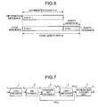
- FIG. 6 is a diagram for explaining the systematic code.
- this systematic code is a code for generating a code sequence by adding a parity sequence, a parity length of which is M, to an information sequence, an information length of which is K.
- FIG. 7 is a diagram of a functional constitution of an encoding/decoding section of a magnetic disk device that uses the conventional LDPC code system.
- this encoding/decoding section includes an LDPC encoder 1 , a Partial Response (PR) channel 2 , a channel A Posteriori Probability (APP) decoder 3 , an LDPC decoder 4 , and a threshold judging unit 5 .
- PR Partial Response
- APP Posteriori Probability
- the LDPC encoder 1 is an encoder that encodes an inputted information sequence u k into an LDPC code sequence x k .
- the PR channel 2 is a channel that records the LDPC code sequence x k encoded by the LDPC encoder 1 in a magnetic disk according to a partial response system, reproduces information y k recorded in the magnetic disk, and outputs the information y k reproduced to the channel APP decoder 3 .
- the channel APP decoder 3 is a decoder that applies Maximum Likelihood (ML) decoding to the information y k received from the PR channel 2 and outputs external information ⁇ e (x k ′) with respect to the LDPC code sequence x k to the LDPC decoder 4 as a logarithmic likelihood ratio.
- ML Maximum Likelihood
- the LDPC decoder 4 is a decoder that performs reliability propagation operation with the external information ⁇ e (x k ′) as a priori likelihood, updates the external information ⁇ e (x k ′) with respect to the LDPC code system x k , and calculates a posteriori probability ⁇ (u k ′) of an estimated value u k ′ with respect to the information sequence u k based on the external information ⁇ e (x k ′).
- This LDPC decoder 4 outputs the external information ⁇ e (x k ′) updated to the channel APP decoder 3 such that the external information ⁇ e (x k ′) is used as a priori information.
- the LDPC decoder 4 repeats the processing a predetermined number of times and, then, outputs information on the a posteriori probability ⁇ (u k ′) to the threshold judging unit 5 .
- the threshold value judging unit 5 can obtain the estimated value u k ′ with respect to the information sequence u k by acquiring the information on the a posterior probability ⁇ (u k ′) from the LDPC decoder 4 and performing threshold judgment for the a posteriori probability ⁇ (u k ′).
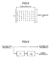
- the LDPC code is a linear block code and defined by a check matrix H.
- FIG. 8 is a diagram of an example of the check matrix H.
- the check matrix H has M rows and N columns.
- the generator matrix G has a relation described below with the information sequence u, the code sequence x, and the check matrix H.
- HG T 0 where 0 is a zero matrix with M rows and K columns.
- the check matrix H and the generator matrix G are held in a memory in a Large Scale Integration (LSI) included in a hard disk device, the circuit scale of the LSI becomes large. Therefore, examinations have been performed to make it possible to easily hold structures of these matrixes in the LSI or easily generate these matrixes.
- LSI Large Scale Integration
- the check matrix H As a method of structuring the check matrix H, there is a method that uses an array code.
- an array-LDPC code obtained by applying the array code to the LDPC code the check matrix H is structured using a cyclic permutation matrix (see, for example, John L. Fan, “Array Codes as Low-Density Parity-Check Codes”, in Proc. 2 nd. Int. Symp. Turbo Codes, Brest, France, September 2000, pp. 543-546).
- ⁇ H [ I I I ⁇ I I ⁇ ⁇ 2 ⁇ ⁇ k - 1 I ⁇ 2 ⁇ 4 ⁇ ⁇ 2 ⁇ ( k - 1 ) ⁇ ⁇ ⁇ ⁇ ⁇ I ⁇ j - 1 ⁇ 2 ⁇ ( j - 1 ) ⁇ ⁇ ( j - 1 ) ⁇ ( k - 1 ) ]
- j and k are a column weight and a row weight of the check matrix H, respectively, relation of j, k ⁇ p.
- ⁇ is a cyclic permutation matrix with p rows and p columns obtained by moving “1”s of the unit matrix I in a row or column direction.
- the array-LDPC code has a characteristic that there is no cycle, length of which is 4, in a Tanner graph and it is possible to prevent deterioration in decoding performance and structure the check matrix H.
- the generator matrix G has a disadvantage that, in general, the generator matrix G does not have a specific structure.
- H [H 1 H 2 ]
- the check matrix H 1 is a matrix generated at random (a random interleaver) and the check matrix H2 has a structure of 1+D (D means delay of 1) represented as follows.
- H 2 [ 1 0 0 0 0 0 1 1 0 0 0 0 0 1 1 0 0 0 0 0 0 1 1 0 0 0 0 0 0 1 1 0 0 0 0 0 0 0 1 1 0 0 0 0 0 1 1 ] where, “+” is an exclusive OR operator.
- FIG. 9 is a diagram for explaining an encoder that performs the conventional IRA-LDPC encoding. As shown in FIG. 9 , this encoder multiplies the information sequence u by a check matrix H 1 T and applies a transfer function 1/(1+D) to an output of the multiplication to thereby generate a parity sequence p from the information sequence u.
- a column weight of the check matrix H 2 in the IRA-LDPC code is 2.
- the LDPC code a column weight of which is 2, is poor in error floor characteristic.
- N low-density parity-check
- an encoder that encodes an information sequence using an array code, includes an information acquiring unit that acquires information concerning a generator matrix defined by a check matrix formed by a matrix obtained by subjecting two “1”s on rows adjacent to each other in a cyclic permutation matrix that forms a check matrix in the array code to row or column permutation arrangement to be arranged predetermined columns apart from each other; an encoding unit that encodes the information sequence into a code sequence based on the information acquired by the information acquiring unit.
- LDPC low-density parity-check
- LDPC low-density parity-check
- LDPC low-density parity-check
- FIG. 1 is a diagram for explaining a cause of occurrence of a 4 cycle according to a first embodiment of the present invention
- FIG. 2 is a diagram for explaining a method of generating a check matrix H 1 according to the first embodiment
- FIGS. 3A to 3 D are diagrams of initial value columns corresponding to various parity lengths
- FIG. 4 is a functional block diagram of an encoder according to the first embodiment
- FIG. 5 is a functional block diagram of a decoder according to the first embodiment
- FIG. 6 is a diagram for explaining a systematic code.
- FIG. 7 is a functional block diagram of a conventional encoding/decoding section
- FIG. 8 is a diagram of an example of a check matrix H.
- FIG. 9 is a diagram of a conventional encoder.
- HG T [ H 1 H 2 ] ⁇ [ I ⁇ ⁇ ( H 2 - 1 H 1 ) T ]
- “+” is an exclusive OR operator.
- ⁇ H 1 [ I I I ⁇ I I ⁇ ⁇ 2 ⁇ ⁇ k - 1 I ⁇ 2 ⁇ 4 ⁇ ⁇ 2 ⁇ ( k - 1 ) ⁇ ⁇ ⁇ ⁇ ⁇ I ⁇ j - 1 ⁇ 2 ⁇ ( j - 1 ) ⁇ ⁇ ( j - 1 ) ⁇ ( k - 1 ) ]
- j and k are a column weight and a row weight of the check matrix H, respectively, and satisfy a relation of j, k ⁇ p, and ⁇ is a cyclic permutation matrix with p rows and p columns obtained by moving “1”s of the unit the unit matrix I in a row or column direction.
- ⁇ H 1 [ ⁇ ⁇ 2 ⁇ ⁇ k - 1 I ⁇ 2 ⁇ 4 ⁇ ⁇ 2 ⁇ ( k - 1 ) I ⁇ ⁇ ⁇ ⁇ ⁇ ⁇ j - 1 ⁇ 2 ⁇ ( j - 1 ) ⁇ ⁇ ( j - 1 ) ⁇ ( k - 1 ) I I I ⁇ I I ]
- p is a prime number because, when p is not a prime number, a cyclic length of a cyclic permutation matrix in the check matrix H 1 is reduced and the check matrix H 1 has a 4 cycle if the check matrix H 1 is created using the cyclic permutation matrix.
- FIG. 1 is a diagram for explaining a cause of occurrence of the 4 cycle.
- a part of the check matrix H 1 is sliced and used to thereby remove the limitation of the number of rows and columns and generate an irregular LDPC code, a column weight and a row weight of which are not uniform.
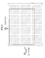
- FIG. 2 is a diagram for explaining a method of generating the check matrix H 1 .
- the check matrix H 1 is generated, first, a check matrix H array in an array code with 21 rows and 28 columns is generated using a cyclic permutation matrix with 7 rows and 7 columns. A matrix with 16 rows and 24 columns is sliced from the check matrix H array and set as the check matrix H 1 .
- the check matrix H 2 is a cyclic permutation matrix with a column weight 3.
- bit positions of “1” are determined such that there is no 4 cycle and an inverse matrix is sparse.
- a sparse matrix means a matrix in which the number of “1” s is extremely small and the number of “0”s is large.
- an inverse matrix a column weight of which is 5, is selected as a sparse inverse matrix.
- the initial value column ⁇ 0, a, b ⁇ (0 ⁇ a, b ⁇ M, and a ⁇ b) is information for specifying a column on which bits of three “1”s are located on a first row of a cyclic permutation matrix, a column weight of which is 3.
- the initial value column ⁇ 0, 2, 6 ⁇ indicates that elements of a first column, an a+1th column, and a b+1th column on a first row of the check matrix H 2 are “1” and the other elements are “0”.
- the check matrix H 2 is a cyclic permutation matrix, it is possible to determine, when an initial value column is determined, all elements of the check matrix H 2 based on the initial value column. Therefore, an encoder does not need to hold values of all the elements of the check matrix H 2 and only has to hold information on the initial value column. Thus, it is possible to realize a reduction of the circuit scale.
- the encoder only has to hold information on an initial value column to generate the inverse matrix H 2 ⁇ 1 .
- it is possible to realize a reduction in the circuit scale and an increase in speed of an arithmetic operation.
- a relation between the parity length satisfying the condition and the initial value column is easily checked through search by a computer.
- a column weight of an inverse matrix When the 4 cycle is permitted, it is possible to set a column weight of an inverse matrix to less than 5. Specifically, it is possible to reduce the column weight of the inverse matrix to 3. It is possible to make the inverse column sparse, reduce computational complexity related to encoding, and reduce the circuit scale by checking the cyclic permutation matrix H 2 , the inverse matrix of which has the column weigh of 3 in this way, through the search by the computer and using the cyclic permutation matrix H 2 .
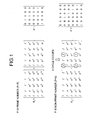
- FIGS. 3A to 3D are diagrams of initial value columns ⁇ 0, a, b ⁇ corresponding to various parity lengths M.
- the comma “,” for marking off numerals of the initial value column ⁇ 0, a, b ⁇ is omitted.
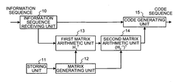
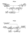
- FIG. 4 is a functional block diagram of an encoder that generates an LDPC code according to the emobodiment.
- the encoder corresponds to the LDPC encoder 1 shown in FIG. 7 .
- the encoder includes an information sequence receiving unit 10 , a storing unit 11 , a matrix generating unit 12 , a first matrix arithmetic unit 13 , a second matrix arithmetic unit 14 , and a code generating unit 15 .
- the information sequence receiving unit 10 receives an information sequence and outputs the information sequence received to the first matrix arithmetic unit 13 and the code generating unit 15 , respectively.
- the storing unit 11 is a storage device like a memory and stores information concerning positions of “1” in the cyclic permutation matrix ⁇ used for generation of the check matrix H 1 , information on an initial value column of the inverse matrix H 2 ⁇ 1 of the check matrix H 2 , information on the numbers of rows and columns of the check matrix H 1 and the inverse matrix H 2 ⁇ 1 , and the like.
- the matrix generating unit 12 acquires the information concerning positions of “1” in the cyclic permutation matrix ⁇ and the information on the number of rows and columns of the check matrix H 1 from the storing unit 11 , generates the check matrix H 1 according to the method explained with reference to FIG. 2 , and outputs a transposed matrix H 1 T of the check matrix H 1 generated to the first matrix arithmetic unit 13 .
- the matrix generating unit 12 acquires the information on an initial value column of the inverse matrix H 2 ⁇ 1 of the check matrix H 2 and information on the number of rows and columns of the inverse matrix H 2 ⁇ 1 from the storing unit 11 , generates the inverse matrix H 2 ⁇ 1 of the check matrix H 2 from the initial value column, and outputs a transposed matrix (H 2 ⁇ 1 ) T of the inverse matrix H 2 generated to the second matrix arithmetic unit 14 .
- the first matrix arithmetic unit 13 calculates a product of the information sequence acquired from the information sequence receiving unit 10 and the transposed matrix H 1 T acquired from the matrix generating unit 12 and outputs information on the product to the second matrix arithmetic unit 14 .
- the second matrix arithmetic unit 14 acquires the information on the product from the first matrix arithmetic unit 13 and calculates a product of the product acquired and the transposed matrix (H 2 ⁇ 1 ) T acquired from the matrix generating unit 12 .
- This product is a parity sequence.
- the second matrix arithmetic unit 14 outputs the parity sequence to the code generating unit 15 .
- the code generating unit 15 adds the parity sequence acquired from the second matrix arithmetic unit 14 to the information sequence acquired from the information sequence receiving unit 10 to thereby generate a code sequence and outputs the code sequence generated.
- FIG. 5 is a functional block diagram of a decoder that decodes an LDPC code according to the embodiment.
- the decoder corresponds to the LDPC decoder 4 shown in FIG. 7 .
- the decoder includes an external information receiving unit 20 , a storing unit 21 , a matrix generating unit 22 , and a decoding processing unit 23 .
- the external information receiving unit 20 receives external information from the channel APP decoder 3 shown in FIG. 7 .
- the storing unit 21 is a storage device such as a memory and stores information concerning positions of “1” in the cyclic permutation matrix ⁇ used for generation of the check matrix H 1 , information on an initial value column of the check matrix H 2 , information on the numbers of rows and columns of the check matrix H 1 and the check matrix H 2 , and the like.
- the matrix generating unit 22 generates the check matrix H based on the information concerning positions of “1” in the cyclic permutation matrix ⁇ , the information on an initial value column of the check matrix H 2 , and the information on the numbers of rows and columns of the check matrix H 1 and the check matrix H 2 and outputs the check matrix H generated to the decoding processing unit 23 .
- the decoding processing unit 23 decodes an LDPC code according to the Sum-Product decoding method generally used. Specifically, the decoding processing unit 23 performs reliability propagation operation with the external information as a priori likelihood using the check matrix H acquired from the matrix generating unit 22 and updates the external information with respect to the LDPC code system x k .
- the decoding processing unit 23 calculates a posteriori probability of an estimated value with respect to the information sequence based on the external information.
- the decoding processing unit 23 outputs the external information updated such that the external information is used as a priori information.
- the decoding processing unit 23 repeats the processing a predetermined number of times and, then, outputs information on the a posteriori probability to the threshold judging unit 5 shown in FIG. 7 .
- the threshold judging unit 5 having received this information can obtain an estimated value with respect to the information sequence by performing threshold judgment for the a posteriori probability. Consequently, decoding of the LDPC code is performed.
- the first matrix arithmetic unit 13 and the second matrix arithmetic unit 14 of the encoder acquire information concerning the generator matrix of the LDPC code defined by the check matrix H with M rows and N columns formed by the check matrix H 2 with M rows and M columns that is a cyclic permutation matrix, an inverse matrix of which exists and a column weight of which is 3, and the check matrix H 1 with M rows and K columns and encode a predetermined information sequence into a code sequence based on the information acquired.
- the decoding processing unit 23 of the decoder acquires information concerning the check matrix H 1 of the LDPC code defined by the check matrix H with M rows and N columns formed by the check matrix H 2 with M rows and M columns that is a cyclic permutation matrix, an inverse matrix of which exists and a column weight of which is 3, and the check matrix H 1 with M rows and K columns and decodes a code sequence based on the information acquired.
- the decoding processing unit 23 of the decoder acquires information concerning the check matrix H 1 of the LDPC code defined by the check matrix H with M rows and N columns formed by the check matrix H 2 with M rows and M columns that is a cyclic permutation matrix, an inverse matrix of which exists and a column weight of which is 3, and the check matrix H 1 with M rows and K columns and decodes a code sequence based on the information acquired.
- the inverse matrix of the check matrix H 2 is a matrix, a column weight of which is 3.
- the check matrix H 2 is a cyclic permutation matrix with a column weight 3, elements of a first column, an a+1th column, and a b+1th column on a first column (0 ⁇ a, b ⁇ M, and a ⁇ b) of which are 1 and other elements on the first row of which is 0.
- the check matrix H 2 is a matrix formed not to satisfy a condition under which a cycle, length of which is 4, occurs in the Tanner graph. Thus, it is possible to prevent deterioration in decoding performance.
- an inverse matrix of the check matrix H 2 is a matrix, a column weight of which is 5.
- the first matrix arithmetic unit 13 encodes an information sequence using the check matrix H 1 and, then, the second matrix arithmetic unit 14 further encodes the information sequence using an inverse matrix of the check matrix H 2 to thereby generate a parity sequence.
- the code generating unit 15 adds the parity sequence generated to the information sequence to thereby encode a predetermined information sequence into a code sequence.
- the check matrix H 1 is a matrix generated by slicing a matrix with M rows and K columns from the check matrix H array with P rows and Q columns (M ⁇ P and K ⁇ Q) in an array code.
- the check matrix H 1 is set as an irregular LDPC code, a column weight and a row weight of which are not uniform.
- the check matrix H is structured. However, if structuring is simply performed, randomness of a check matrix may fall to make it difficult to improve error correction ability.
- the check matrix H according to the second embodiment is explained.
- the check matrix H 1 is formed as follows by a product of respective column blocks of the check matrix H array in an array code and ⁇ m (0 ⁇ m ⁇ k ⁇ 1) formed by a cyclic permutation matrix ⁇ explained later.
- H 1 [ I I ⁇ ⁇ ⁇ I ⁇ ⁇ ⁇ 2 ⁇ I ⁇ ⁇ ⁇ k - 1 I s ⁇ ⁇ ⁇ s 2 ⁇ ⁇ 2 ⁇ s k - 1 ⁇ ⁇ k - 1 I s 2 ⁇ ⁇ s 4 ⁇ ⁇ 2 ⁇ s 2 ⁇ ( k - 1 ) ⁇ ⁇ k - 1 ⁇ ⁇ ⁇ ⁇ I j - 1 ⁇ ⁇ s 2 ⁇ ( j - 1 ) ⁇ ⁇ 2 ⁇ s ( j - 1 ) ⁇ ( k - 1 ) ⁇ ⁇ k - 1 ]
- j and k are a column weight and a row weight of the check matrix H, respectively, relation of j, k ⁇ p.
- ⁇ is a cyclic permutation matrix with p rows and p columns same as that in the first embodiment that forms an array code.
- ⁇ [ 0 1 0 0 0 0 0 0 1 0 0 0 0 0 1 0 0 0 0 0 1 1 0 0 0 0 0 ]
- the cycle permutation matrix ⁇ is a matrix with p rows and p columns and is a matrix obtained by subjecting two “1”s on rows adjacent to each other in the cyclic permutation matrix ⁇ to row or column permutation arrangement to be arranged predetermined columns apart from each other .
- cyclic matrix ⁇ in the first embodiment, “1”s are arranged on a diagonal.
- it it is possible to disperse “1”s arranged on the diagonal by using such a pseudo-random cyclic permutation matrix ⁇ and imitate the random interleaver. This is effective for improvement of error correction ability when there is intersymbol interference as in codes in a magnetic disk device.
- it is also possible to slice an arbitrary part of the check matrix H 1 and use the part as the check matrix H 1 .
- the encoder and the decoder shown in FIGS. 4 and 5 perform encoding of an information sequence and decoding of a code sequence using the generator matrix G corresponding to the check matrix H formed in this way and the check matrix H.
- the first matrix arithmetic unit 13 and the second matrix arithmetic unit 14 of the encoder acquire information concerning the generator matrix defined by the check matrix H formed by the matrix ⁇ , which is obtained by subjecting two “1”s on rows adjacent to each other in the cyclic permutation matrix ⁇ that forms the check matrix H array in an array code to row or column permutation arrangement to be arranged predetermined columns apart from each other, and encode an information sequence into a code sequence based on the information acquired.
- it is possible to imitate the random interleaver prevent a decline in error correction ability by controlling error propagation among bits even when there is intersymbol interference, reduce computational complexity related to encoding by structuring a matrix, and reduce the circuit scale.
- the matrix generating unit 12 of the encoder generates information concerning a generator matrix by calculating a product of the matrix ⁇ , which is obtained by subjecting two “1”s on rows adjacent to each other in the cyclic permutation matrix ⁇ that forms the check matrix H array in an array code to row or column permutation arrangement to be arranged predetermined columns apart from each other, and the cyclic permutation matrix ⁇ .
- the first matrix arithmetic unit 13 and the second matrix arithmetic unit 14 acquire the information generated.
- the present invention has been explained.
- the present invention may be carried out in various different embodiments within a scope of the technical idea described in patent claims other than the embodiments described above.
- the present invention is not limited to the application to error correction for a magnetic disk device and may be applied to error correction for an optical disk storage device and communication.
- all or a part of the kinds of processing explained as being automatically performed may be manually performed. All or a part of the kinds of processing explained as manually performed may be automatically performed according to a publicly known method.
- the respective components of the encoder and the decoder shown in the figures are functionally conceptual and are not always required to be physically constituted as shown in the figure.
- specific forms of distribution and integration of the encoder and the decoder are not limited to those shown in the figures. It is possible to constitute all or a part of the devices to be functionally or physically distributed and integrated by an arbitrary unit according to various loads, states of use, and the like.
- all or a part of the various processing functions performed in the encoder and the decoder can be realized by a CPU and programs analyzed and executed by the CPU or can be realized as hardware according to the wired logic.
- the encoder acquires information concerning a generator matrix of an LDPC code defined by a check matrix with M rows and N columns formed by a first matrix with M rows and M columns that is a cyclic permutation matrix, an inverse matrix of which is present and a column weight of which is 3, and a second matrix with M rows and K columns and encodes a predetermined information sequence with a code sequence based on the information acquired.
- the decoder acquires information concerning a check matrix with M rows and N columns of an LDPC code defined by the check matrix formed by a first matrix with M rows and M columns that is a cyclic permutation matrix, an inverse matrix of which is present and a column weight of which is 3, and a second matrix with M rows and K columns and decodes a code sequence based on the information acquired.
- an inverse matrix of the first matrix is a matrix, a column weight of which is 3.
- the first matrix is a cyclic permutation matrix with a column weight 3, elements of a first column, an a+1th column, and a b+1th column on a first column (0 ⁇ a, b ⁇ M, and a ⁇ b) of which are 1 and other elements on the first row of which is 0.
- the first matrix is a matrix formed not to satisfy a condition under which a cycle, length of which is 4, occurs in the Tanner graph.
- an inverse matrix of the first matrix is a matrix, a column weight of which is 5.
- the information sequence after encoding an information sequence using the second matrix, the information sequence is further encoded using an inverse matrix of the first matrix to thereby generate a parity sequence, a predetermined information sequence is encoded into a code sequence by adding the parity sequence generated to the information sequence.
- the second matrix is formed by a matrix obtained by subjecting two “1”s on rows adjacent to each other in a cyclic permutation matrix that forms a check matrix in an array code to row or column permutation arrangement to be arranged predetermined columns apart from each other.
- the second matrix is a matrix generated by slicing a matrix with M rows and K columns from a check matrix with P rows and Q columns (M ⁇ P and K ⁇ Q) in an array code.
- information concerning a generator matrix defined by a check matrix formed by a matrix obtained by subjecting two “1”s on rows adjacent to each other in a cyclic permutation matrix that forms a check matrix in an array code to row or column permutation arrangement to be arranged predetermined columns apart from each other is acquired and an information sequence is encoded into a code sequence based on the information acquired.
- information concerning a generator matrix is generated by calculating a product of a matrix obtained by subjecting two “1”s on rows adjacent to each other in a cyclic permutation matrix that forms a check matrix in an array code to row or column permutation arrangement to be arranged predetermined columns apart from each other and the cyclic permutation matrix and the information generated is acquired.
Abstract
Description
- 1. Field of the Invention
- The present invention relates to an encoder that encodes information using a low-density parity-check (LDPC) code and a decoder that decodes the encoded information using the LDPC code. More specifically, the present invention relates to an encoder that encodes information using an array code and a decoder that decodes the encoded information.
- 2. Description of the Related Art
- Low-density parity-check (LDPC) codes are attracting attention as error correction technology. The LDPC code is advantageous in that it is a linear code having fewer “1”s in a check matrix. Because the code length is higher and the codes have randomness, the LDPC code has significantly higher error correction ability than the conventional code. With the LDPC code it is possible to efficiently decode a code sequence using an iterative decoding method called a Sum-Product decoding method.
- The LDPC code is applied to detect errors in magnetic disk devices. An LDPC code that can be used to detect errors in magnetic disk devices need to have, for example, satisfactory waterfall characteristic, low error floor, short parity length, high encoding rate, short code length, and it should be a systematic code. Moreover, circuit scales of an encoder and a decoder should be small. An LDPC code that can fulfill all of these requirements has yet to be developed.
- The systematic code is a code generated by generating a parity sequence from an information sequence and adding the parity sequence to the information sequence.
FIG. 6 is a diagram for explaining the systematic code. - As shown in
FIG. 6 , this systematic code is a code for generating a code sequence by adding a parity sequence, a parity length of which is M, to an information sequence, an information length of which is K. A code length of the code sequence is N (N=K+M). -
FIG. 7 is a diagram of a functional constitution of an encoding/decoding section of a magnetic disk device that uses the conventional LDPC code system. As shown inFIG. 7 , this encoding/decoding section includes an LDPC encoder 1, a Partial Response (PR) channel 2, a channel A Posteriori Probability (APP) decoder 3, an LDPC decoder 4, and a threshold judging unit 5. - The LDPC encoder 1 is an encoder that encodes an inputted information sequence uk into an LDPC code sequence xk. The PR channel 2 is a channel that records the LDPC code sequence xk encoded by the LDPC encoder 1 in a magnetic disk according to a partial response system, reproduces information yk recorded in the magnetic disk, and outputs the information yk reproduced to the channel APP decoder 3.
- The channel APP decoder 3 is a decoder that applies Maximum Likelihood (ML) decoding to the information yk received from the PR channel 2 and outputs external information Λe (xk′) with respect to the LDPC code sequence xk to the LDPC decoder 4 as a logarithmic likelihood ratio.
- The LDPC decoder 4 is a decoder that performs reliability propagation operation with the external information Λe (xk′) as a priori likelihood, updates the external information Λe (xk′) with respect to the LDPC code system xk, and calculates a posteriori probability Λ(uk′) of an estimated value uk′ with respect to the information sequence uk based on the external information Λe (xk′).
- This LDPC decoder 4 outputs the external information Λe (xk′) updated to the channel APP decoder 3 such that the external information Λe (xk′) is used as a priori information. The LDPC decoder 4 repeats the processing a predetermined number of times and, then, outputs information on the a posteriori probability Λ(uk′) to the threshold judging unit 5.
- The threshold value judging unit 5 can obtain the estimated value uk′ with respect to the information sequence uk by acquiring the information on the a posterior probability Λ(uk′) from the LDPC decoder 4 and performing threshold judgment for the a posteriori probability Λ(uk′).
- The LDPC code is a linear block code and defined by a check matrix H.
FIG. 8 is a diagram of an example of the check matrix H. When the code length is N and the parity length is M, the check matrix H has M rows and N columns. - The check matrix H and a code matrix x are related as follows:
Hx T=0
where x is an N-dimensional vector, 0 is an N-dimensional zero vector, and T represents transposition of x. - When the code sequence x is generated from the information sequence u, a generator matrix G described below is used:
x=uG
where the information sequence u is a K-dimensional vector and the generator matrix G is a matrix with K rows and N columns. - The generator matrix G has a relation described below with the information sequence u, the code sequence x, and the check matrix H.
HG T=0
where 0 is a zero matrix with M rows and K columns. - If the check matrix H and the generator matrix G are held in a memory in a Large Scale Integration (LSI) included in a hard disk device, the circuit scale of the LSI becomes large. Therefore, examinations have been performed to make it possible to easily hold structures of these matrixes in the LSI or easily generate these matrixes.
- For example, as a method of structuring the check matrix H, there is a method that uses an array code. In an array-LDPC code obtained by applying the array code to the LDPC code, the check matrix H is structured using a cyclic permutation matrix (see, for example, John L. Fan, “Array Codes as Low-Density Parity-Check Codes”, in Proc. 2nd. Int. Symp. Turbo Codes, Brest, France, September 2000, pp. 543-546).
- An example of the check matrix H of the array-LDPC code is shown below:
where I is a unit pixel with p rows and p columns (p is a prime number: p=1, 3, 5, 7, 11, . . . ). j and k are a column weight and a row weight of the check matrix H, respectively, relation of j, k≦p. - σ is a cyclic permutation matrix with p rows and p columns obtained by moving “1”s of the unit matrix I in a row or column direction. An example of σ is shown below:
- The array-LDPC code has a characteristic that there is no cycle, length of which is 4, in a Tanner graph and it is possible to prevent deterioration in decoding performance and structure the check matrix H. However, the generator matrix G has a disadvantage that, in general, the generator matrix G does not have a specific structure.
- Therefore, a method of recursively performing encoding of an information sequence using a structured check matrix has also been proposed. However, computational complexity at the time of encoding increases (see, for example, U.S. Pat. No. 6,895,547 specification).
- An Irregular Repeat-Accumulate (IRA)-LDPC code that holds down computational complexity at the time of encoding and realizes a low error floor has also been proposed (see, for example, M. Yang, W. E. Ryan, and Y. Li, “Design of efficiently encodable moderate-length high-rate irregular LDPC codes,” IEEE Trans. Comm., Vol. 52, No. 4, pp. 564-571, April 2004).
- In this IRA-LDPC code, the check matrix H with M rows and N columns is divided into a square matrix H2 with M rows and M columns and a matrix H1 with the remaining M rows and K columns (K=N−M).
H=[H 1 H 2] - In this case, the generator matrix G is represented as follows.
G=[I(H 2 −1 H 1)T] - In the IRA-LDPC code, the check matrix H1 is a matrix generated at random (a random interleaver) and the check matrix H2 has a structure of 1+D (D means delay of 1) represented as follows.
where, “+” is an exclusive OR operator. -
FIG. 9 is a diagram for explaining an encoder that performs the conventional IRA-LDPC encoding. As shown inFIG. 9 , this encoder multiplies the information sequence u by a check matrix H1 T and applies a transfer function 1/(1+D) to an output of the multiplication to thereby generate a parity sequence p from the information sequence u. - However, if the conventional IRA-LDPC code is applied to an apparatus that permits intersymbol interference, like a magnetic disk device using the partial response system, if there is a portion where “1” continues in the check matrix H, error rate characteristic is not satisfactory.
- Specifically, a column weight of the check matrix H2 in the IRA-LDPC code is 2. When there is intersymbol interference, error propagation among bits tends to occur and a decline in error correction ability is inevitable. It is generally known that the LDPC code, a column weight of which is 2, is poor in error floor characteristic.
- Therefore, there is a need of a technology that can control deterioration in error rate characteristic, reduce computational complexity related to encoding and decoding, and reduce circuit scales of an encoding circuit and a decoding circuit while structuring a check matrix.
- It is an object of the present invention to at least solve the problems in the conventional technology.
- According to an aspect of the present invention, an encoder that encodes information sequence having a code length of N (N=K+M), where K is information length and M is parity length, into a code sequence by using a low-density parity-check (LDPC) code, includes an information acquiring unit that acquires information concerning a generator matrix of an LDPC code defined by a check matrix with M rows and N columns formed by a first matrix with M rows and M columns that is a cyclic permutation matrix, an inverse matrix of which exists and a column weight of which is 3, and a second matrix with M rows and K columns; and an encoding unit that encodes predetermined information sequence into a code sequence based on the information acquired by the information acquiring unit.
- According to another aspect of the present invention, an encoder that encodes an information sequence using an array code, includes an information acquiring unit that acquires information concerning a generator matrix defined by a check matrix formed by a matrix obtained by subjecting two “1”s on rows adjacent to each other in a cyclic permutation matrix that forms a check matrix in the array code to row or column permutation arrangement to be arranged predetermined columns apart from each other; an encoding unit that encodes the information sequence into a code sequence based on the information acquired by the information acquiring unit.
- According to still another aspect of the present invention, a decoder that adds a parity sequence, a parity length of which is M, to a predetermined information sequence, an information length of which is K, to thereby decode the code sequence, a code length of which is N (N=K+M), encoded using a low-density parity-check (LDPC) code, includes an information acquiring unit that acquires information concerning a check matrix with M rows and N columns of an LDPC code defined by the check matrix formed by a first matrix with M rows and M columns that is a cyclic permutation matrix, an inverse matrix of which exists and a column weight of which is 3, and a second matrix with M rows and K columns; and a decoding unit that decodes a code sequence based on the information acquired by the information acquiring unit.
- According to still another aspect of the present invention, a method of encoding including adding a parity sequence, a parity length of which is M, to a predetermined information sequence, an information length of which is K, to thereby encoding the information sequence into a code sequence, a code length of which is N (N=K+M), using a low-density parity-check (LDPC) code, includes acquiring information concerning a generator matrix of an LDPC code defined by a check matrix with M rows and N columns formed by a first matrix with M rows and M columns that is a cyclic permutation matrix, an inverse matrix of which exists and a column weight of which is 3, and a second matrix with M rows and K columns; and encoding predetermined information sequence into a code sequence based on the information acquired at the acquiring.
- According to still another aspect of the present invention, a method of decoding including adding a parity sequence, a parity length of which is M, to a predetermined information sequence, an information length of which is K, to thereby decode the code sequence, a code length of which is N (N=K+M), encoded using a low-density parity-check (LDPC) code, includes acquiring information concerning a check matrix with M rows and N columns of an LDPC code defined by the check matrix formed by a first matrix with M rows and M columns that is a cyclic permutation matrix, an inverse matrix of which exists and a column weight of which is 3, and a second matrix with M rows and K columns; and decoding a code sequence based on the information acquired at the acquiring.
- The above and other objects, features, advantages and technical and industrial significance of this invention will be better understood by reading the following detailed description of presently preferred embodiments of the invention, when considered in connection with the accompanying drawings.
-
FIG. 1 is a diagram for explaining a cause of occurrence of a 4 cycle according to a first embodiment of the present invention; -
FIG. 2 is a diagram for explaining a method of generating a check matrix H1 according to the first embodiment; -
FIGS. 3A to 3D are diagrams of initial value columns corresponding to various parity lengths; -
FIG. 4 is a functional block diagram of an encoder according to the first embodiment; -
FIG. 5 is a functional block diagram of a decoder according to the first embodiment; -
FIG. 6 is a diagram for explaining a systematic code. -
FIG. 7 is a functional block diagram of a conventional encoding/decoding section; -
FIG. 8 is a diagram of an example of a check matrix H; and -
FIG. 9 is a diagram of a conventional encoder. - Exemplary embodiments of the present invention are explained in detail below with reference to the accompanying drawings.
- In an LDPC code according to a first embodiment of the present invention, a check matrix H with M rows and N columns is formed of two matrixes, namely, a check matrix H2 that is a square matrix with M rows and M columns and a check matrix H1 with the remaining M rows and K columns (K=N−M) as shown below:
H=[H 1 H 2].
A generator matrix G can be represented as follows:
G=[I(H 2 −1 H 1)T].
In other words,
“+” is an exclusive OR operator. - An array code is used for the check matrix H1. In this case, the check matrix H1 is represented as follows.
where I is a unit matrix with p rows and p columns (p is a prime number: p=1, 3, 5, 7, 11, . . . ). j and k are a column weight and a row weight of the check matrix H, respectively, and satisfy a relation of j, k≦p, and σ is a cyclic permutation matrix with p rows and p columns obtained by moving “1”s of the unit the unit matrix I in a row or column direction. The following is an example in which “1”s are moved in the row direction:
The following is an example in which “1”s are moved in the row direction: - In the check matrix H1, an element at the upper left corner is set as I (=σ0). It is also possible that the element at the upper left corner of the check matrix H1 is set to an arbitrary element σn (n≦(j−1) (k−1)) and a matrix obtained by causing the remaining elements to cycle in the row or column direction is used as the check matrix H1.
- For example, when σ (=σ1) is the element at the upper left corner, the remaining elements are caused to cycle as follows to generate the check matrix H1.
where p is a prime number because, when p is not a prime number, a cyclic length of a cyclic permutation matrix in the check matrix H1 is reduced and the check matrix H1 has a 4 cycle if the check matrix H1 is created using the cyclic permutation matrix. - However, when p is a prime number and a cyclic length of the cyclic permutation matrix is larger than the number of rows and columns of the check matrix H1, the 4 cycle does not occur. This condition is represented as j, k≦p (p is a prime number).
FIG. 1 is a diagram for explaining a cause of occurrence of the 4 cycle. - As shown in
FIG. 1 , it is seen that, whereas the 4 cycle does not occur in the matrix H1 when p is a prime number 5, a cyclic length of the cyclic permutation matrix is reduced to cause the 4 cycle due to a cyclic matrix I when p is a non-prime number 6. - Such an array code defined by the check matrix H1 with (j×p) rows and (k×p) columns, a column weight of which is j and a row weight of which is k, is a regular LDPC code and the number of rows and columns are limited. Thus, a part of the check matrix H1 is sliced and used to thereby remove the limitation of the number of rows and columns and generate an irregular LDPC code, a column weight and a row weight of which are not uniform.
-
FIG. 2 is a diagram for explaining a method of generating the check matrix H1. An example in which p=7, j=3, and k=4 and the check matrix H1 with 16 rows and 24 columns is generated is shown inFIG. 2 . When the check matrix H1 is generated, first, a check matrix Harray in an array code with 21 rows and 28 columns is generated using a cyclic permutation matrix with 7 rows and 7 columns. A matrix with 16 rows and 24 columns is sliced from the check matrix Harray and set as the check matrix H1. - On the other hand, the check matrix H2 is a cyclic permutation matrix with a column weight 3. However, bit positions of “1” are determined such that there is no 4 cycle and an inverse matrix is sparse. A sparse matrix means a matrix in which the number of “1” s is extremely small and the number of “0”s is large. In this explanation, an inverse matrix, a column weight of which is 5, is selected as a sparse inverse matrix.
- The check matrix H2 shown below is an example in which a parity length is 16 and an initial value column is {0, 2, 6}.
- The initial value column {0, a, b} (0<a, b<M, and a<b) is information for specifying a column on which bits of three “1”s are located on a first row of a cyclic permutation matrix, a column weight of which is 3. Specifically, the initial value column {0, 2, 6} indicates that elements of a first column, an a+1th column, and a b+1th column on a first row of the check matrix H2 are “1” and the other elements are “0”.
- Since the check matrix H2 is a cyclic permutation matrix, it is possible to determine, when an initial value column is determined, all elements of the check matrix H2 based on the initial value column. Therefore, an encoder does not need to hold values of all the elements of the check matrix H2 and only has to hold information on the initial value column. Thus, it is possible to realize a reduction of the circuit scale.
- An inverse matrix H2 −1 of the check matrix H2 is:
- In this way, when the check matrix H2 is the matrix with the initial value column {0, 2, 6}, a column weight of the inverse matrix H2 −1 is 5. Like the check matrix H2, the inverse matrix H2 −1 is also a cyclic permutation matrix. Therefore, the encoder only has to hold information on an initial value column to generate the inverse matrix H2 −1. Thus, it is possible to realize a reduction in the circuit scale and an increase in speed of an arithmetic operation.
- An initial value column of the cyclic permutation matrix H2 with a column weight 3, which has no 4 cycle and an inverse matrix of which exists and has a column weight 5, depends on a parity length. A relation between the parity length satisfying the condition and the initial value column is easily checked through search by a computer.
- When the 4 cycle is permitted, it is possible to set a column weight of an inverse matrix to less than 5. Specifically, it is possible to reduce the column weight of the inverse matrix to 3. It is possible to make the inverse column sparse, reduce computational complexity related to encoding, and reduce the circuit scale by checking the cyclic permutation matrix H2, the inverse matrix of which has the column weigh of 3 in this way, through the search by the computer and using the cyclic permutation matrix H2.
- A result of the search for an initial value column performed by the computer is described below.
FIGS. 3A to 3D are diagrams of initial value columns {0, a, b} corresponding to various parity lengths M. InFIGS. 3A to 3D, the comma “,” for marking off numerals of the initial value column {0, a, b} is omitted. - The cyclic permutation matrix H2 with the column weight 3, the parity length of which is M and the initial value column of which is {0, a, b}, has the 4 cycle when any one of the following conditions is satisfied:
a=b−a (1)
b−a=M−b (2)
M−b=a (3)
b=M−b (4)
M−a=a (5)
M−b+a=b−a. (6) - Therefore, at the time of search for an initial value column, an initial value column satisfying such a condition is excluded.
-
FIG. 4 is a functional block diagram of an encoder that generates an LDPC code according to the emobodiment. The encoder corresponds to the LDPC encoder 1 shown inFIG. 7 . The encoder includes an information sequence receiving unit 10, a storing unit 11, a matrix generating unit 12, a first matrix arithmetic unit 13, a second matrix arithmetic unit 14, and a code generating unit 15. - The information sequence receiving unit 10 receives an information sequence and outputs the information sequence received to the first matrix arithmetic unit 13 and the code generating unit 15, respectively. The storing unit 11 is a storage device like a memory and stores information concerning positions of “1” in the cyclic permutation matrix σ used for generation of the check matrix H1, information on an initial value column of the inverse matrix H2 −1 of the check matrix H2, information on the numbers of rows and columns of the check matrix H1 and the inverse matrix H2 −1, and the like.
- The matrix generating unit 12 acquires the information concerning positions of “1” in the cyclic permutation matrix σ and the information on the number of rows and columns of the check matrix H1 from the storing unit 11, generates the check matrix H1 according to the method explained with reference to
FIG. 2 , and outputs a transposed matrix H1 T of the check matrix H1 generated to the first matrix arithmetic unit 13. - The matrix generating unit 12 acquires the information on an initial value column of the inverse matrix H2 −1 of the check matrix H2 and information on the number of rows and columns of the inverse matrix H2 −1 from the storing unit 11, generates the inverse matrix H2 −1 of the check matrix H2 from the initial value column, and outputs a transposed matrix (H2 −1)T of the inverse matrix H2generated to the second matrix arithmetic unit 14.
- The first matrix arithmetic unit 13 calculates a product of the information sequence acquired from the information sequence receiving unit 10 and the transposed matrix H1 T acquired from the matrix generating unit 12 and outputs information on the product to the second matrix arithmetic unit 14.
- The second matrix arithmetic unit 14 acquires the information on the product from the first matrix arithmetic unit 13 and calculates a product of the product acquired and the transposed matrix (H2 −1)T acquired from the matrix generating unit 12. This product is a parity sequence. The second matrix arithmetic unit 14 outputs the parity sequence to the code generating unit 15.
- The code generating unit 15 adds the parity sequence acquired from the second matrix arithmetic unit 14 to the information sequence acquired from the information sequence receiving unit 10 to thereby generate a code sequence and outputs the code sequence generated.
-
FIG. 5 is a functional block diagram of a decoder that decodes an LDPC code according to the embodiment. The decoder corresponds to the LDPC decoder 4 shown inFIG. 7 . The decoder includes an external information receiving unit 20, a storing unit 21, a matrix generating unit 22, and a decoding processing unit 23. - The external information receiving unit 20 receives external information from the channel APP decoder 3 shown in
FIG. 7 . The storing unit 21 is a storage device such as a memory and stores information concerning positions of “1” in the cyclic permutation matrix σ used for generation of the check matrix H1, information on an initial value column of the check matrix H2, information on the numbers of rows and columns of the check matrix H1 and the check matrix H2, and the like. - The matrix generating unit 22 generates the check matrix H based on the information concerning positions of “1” in the cyclic permutation matrix σ, the information on an initial value column of the check matrix H2, and the information on the numbers of rows and columns of the check matrix H1 and the check matrix H2 and outputs the check matrix H generated to the decoding processing unit 23.
- The decoding processing unit 23 decodes an LDPC code according to the Sum-Product decoding method generally used. Specifically, the decoding processing unit 23 performs reliability propagation operation with the external information as a priori likelihood using the check matrix H acquired from the matrix generating unit 22 and updates the external information with respect to the LDPC code system xk.
- The decoding processing unit 23 calculates a posteriori probability of an estimated value with respect to the information sequence based on the external information. The decoding processing unit 23 outputs the external information updated such that the external information is used as a priori information.
- The decoding processing unit 23 repeats the processing a predetermined number of times and, then, outputs information on the a posteriori probability to the threshold judging unit 5 shown in
FIG. 7 . The threshold judging unit 5 having received this information can obtain an estimated value with respect to the information sequence by performing threshold judgment for the a posteriori probability. Consequently, decoding of the LDPC code is performed. - As described above, in the first embodiment, the first matrix arithmetic unit 13 and the second matrix arithmetic unit 14 of the encoder acquire information concerning the generator matrix of the LDPC code defined by the check matrix H with M rows and N columns formed by the check matrix H2 with M rows and M columns that is a cyclic permutation matrix, an inverse matrix of which exists and a column weight of which is 3, and the check matrix H1 with M rows and K columns and encode a predetermined information sequence into a code sequence based on the information acquired. Thus, it is possible to control error propagation among bits by setting the column weight to 3 even when there is intersymbol interference, improve error floor characteristic to prevent a decline in error correction ability, reduce computational complexity related to encoding by structuring the first matrix, and reduce the circuit scale.
- In the first embodiment, the decoding processing unit 23 of the decoder acquires information concerning the check matrix H1 of the LDPC code defined by the check matrix H with M rows and N columns formed by the check matrix H2 with M rows and M columns that is a cyclic permutation matrix, an inverse matrix of which exists and a column weight of which is 3, and the check matrix H1 with M rows and K columns and decodes a code sequence based on the information acquired. Thus, it is possible to control error propagation among bits by setting the column weight to 3 even when there is intersymbol interference, improve error floor characteristic to prevent a decline in error correction ability, reduce computational complexity related to encoding by structuring the first matrix, and reduce the circuit scale.
- In the first embodiment, when occurrence of a cycle, length of which is 4, is permitted in the Tanner graph, the inverse matrix of the check matrix H2 is a matrix, a column weight of which is 3. Thus, it is possible to set the inverse matrix as a sparse matrix and reduce computational complexity related to encoding.
- In the first embodiment, the check matrix H2 is a cyclic permutation matrix with a column weight 3, elements of a first column, an a+1th column, and a b+1th column on a first column (0<a, b<M, and a<b) of which are 1 and other elements on the first row of which is 0. Thus, it is possible to generate the first matrix simply by storing positions of elements of 1 on the first row and it is possible to reduce the circuit scale because it is unnecessary to store all elements of the first matrix.
- In the first embodiment, the check matrix H2 is a matrix formed not to satisfy a condition under which a cycle, length of which is 4, occurs in the Tanner graph. Thus, it is possible to prevent deterioration in decoding performance.
- In the first embodiment, a condition under which a cycle, length of which is 4, occurs is that any one of a=b−a, b−a=M−b, M−b=a, b=M−b, M−a=a, and M−b+a=b−a is satisfied. Thus, it is possible to efficiently prevent deterioration in decoding performance by generating the first matrix not to satisfy this condition.
- In the first embodiment, when the check matrix H2 is a matrix formed not to satisfy a condition under which a cycle, length of which is 4, occurs in the Tanner graph, an inverse matrix of the check matrix H2 is a matrix, a column weight of which is 5. Thus, it is possible to set the inverse matrix as a sparse matrix and reduce computational complexity related to encoding.
- In the first embodiment, the first matrix arithmetic unit 13 encodes an information sequence using the check matrix H1 and, then, the second matrix arithmetic unit 14 further encodes the information sequence using an inverse matrix of the check matrix H2 to thereby generate a parity sequence. The code generating unit 15 adds the parity sequence generated to the information sequence to thereby encode a predetermined information sequence into a code sequence. Thus, it is possible to efficiently perform encoding of an information sequence using the check matrix H2 and the check matrix H1 that form a check matrix with M rows and N columns.
- In the first embodiment, the check matrix H1 is a matrix generated by slicing a matrix with M rows and K columns from the check matrix Harray with P rows and Q columns (M<P and K<Q) in an array code. Thus, it is possible to set the check matrix H1 as an irregular LDPC code, a column weight and a row weight of which are not uniform.
- In the first embodiment, the check matrix H is structured. However, if structuring is simply performed, randomness of a check matrix may fall to make it difficult to improve error correction ability.
- There is the random interleaver as a technology for improving randomness of a check matrix. However, since it is necessary to prepare a plurality of memories that store code sequences, the circuit scale is increased. Therefore, in a second embodiment, randomness of a check matrix is improved without increasing the circuit scale. Functional constitutions of an encoder and a decoder are the same as those shown in
FIGS. 4 and 5 . Differences from the first embodiment are explained in detail below. - First, the check matrix H according to the second embodiment is explained. As in the first embodiment, the check matrix H with M rows and N columns is divided into the check matrix H2 that is a square matrix with M rows and N columns and the check matrix H1 with the remaining M rows and K columns (K=N−M) as shown below:
H=[H 1 H 2]. - A matrix same as the check matrix H2 in the first embodiment is used as the check matrix H2 in the second embodiment. The check matrix H1 is formed as follows by a product of respective column blocks of the check matrix Harray in an array code and ωm (0≦m≦k−1) formed by a cyclic permutation matrix ω explained later.
where I is a unit pixel with p rows and p columns (p is a prime number: p=1, 3, 5, 7, 11, . . . ). j and k are a column weight and a row weight of the check matrix H, respectively, relation of j, k≦p. - As shown in an example below, σ is a cyclic permutation matrix with p rows and p columns same as that in the first embodiment that forms an array code.
- The cycle permutation matrix ω is a matrix with p rows and p columns and is a matrix obtained by subjecting two “1”s on rows adjacent to each other in the cyclic permutation matrix σ to row or column permutation arrangement to be arranged predetermined columns apart from each other . For example, the cyclic permutation matrix ω obtained by subjecting two “1”s on rows adjacent to each other to row or column permutation arrangement to be arranged one column apart from each other is represented as below:
- In the cyclic matrix σ in the first embodiment, “1”s are arranged on a diagonal. However, it it is possible to disperse “1”s arranged on the diagonal by using such a pseudo-random cyclic permutation matrix ω and imitate the random interleaver. This is effective for improvement of error correction ability when there is intersymbol interference as in codes in a magnetic disk device. As explained with reference to
FIG. 2 , it is also possible to slice an arbitrary part of the check matrix H1 and use the part as the check matrix H1. - The encoder and the decoder shown in
FIGS. 4 and 5 perform encoding of an information sequence and decoding of a code sequence using the generator matrix G corresponding to the check matrix H formed in this way and the check matrix H. - Thus, in the second embodiment, the first matrix arithmetic unit 13 and the second matrix arithmetic unit 14 of the encoder acquire information concerning the generator matrix defined by the check matrix H formed by the matrix ω, which is obtained by subjecting two “1”s on rows adjacent to each other in the cyclic permutation matrix σ that forms the check matrix Harray in an array code to row or column permutation arrangement to be arranged predetermined columns apart from each other, and encode an information sequence into a code sequence based on the information acquired. Thus, it is possible to imitate the random interleaver, prevent a decline in error correction ability by controlling error propagation among bits even when there is intersymbol interference, reduce computational complexity related to encoding by structuring a matrix, and reduce the circuit scale.
- In the second embodiment, the matrix generating unit 12 of the encoder generates information concerning a generator matrix by calculating a product of the matrix ω, which is obtained by subjecting two “1”s on rows adjacent to each other in the cyclic permutation matrix σ that forms the check matrix Harray in an array code to row or column permutation arrangement to be arranged predetermined columns apart from each other, and the cyclic permutation matrix σ. The first matrix arithmetic unit 13 and the second matrix arithmetic unit 14 acquire the information generated. Thus, it is possible to make a storage device in which the information concerning the generator matrix is stored in advance unnecessary.
- The embodiments of the present invention have been explained. The present invention may be carried out in various different embodiments within a scope of the technical idea described in patent claims other than the embodiments described above. For example, the present invention is not limited to the application to error correction for a magnetic disk device and may be applied to error correction for an optical disk storage device and communication.
- Among the respective kinds of processing explained in the embodiments, all or a part of the kinds of processing explained as being automatically performed may be manually performed. All or a part of the kinds of processing explained as manually performed may be automatically performed according to a publicly known method.
- Besides, it is possible to arbitrarily change the processing procedures, the control procedures, the specific names, and the information including various data and parameters unless specifically noted otherwise.
- The respective components of the encoder and the decoder shown in the figures are functionally conceptual and are not always required to be physically constituted as shown in the figure. In other words, specific forms of distribution and integration of the encoder and the decoder are not limited to those shown in the figures. It is possible to constitute all or a part of the devices to be functionally or physically distributed and integrated by an arbitrary unit according to various loads, states of use, and the like.
- Moreover, all or a part of the various processing functions performed in the encoder and the decoder can be realized by a CPU and programs analyzed and executed by the CPU or can be realized as hardware according to the wired logic.
- According to the present invention, the encoder acquires information concerning a generator matrix of an LDPC code defined by a check matrix with M rows and N columns formed by a first matrix with M rows and M columns that is a cyclic permutation matrix, an inverse matrix of which is present and a column weight of which is 3, and a second matrix with M rows and K columns and encodes a predetermined information sequence with a code sequence based on the information acquired. Thus, there is an effect that it is possible to control error propagation among bits by setting the column weight to 3 even when there is intersymbol interference, improve error floor characteristic to prevent a decline in error correction ability, reduce computational complexity related to encoding by structuring the first matrix, and reduce the circuit scale.
- According to the present invention, the decoder acquires information concerning a check matrix with M rows and N columns of an LDPC code defined by the check matrix formed by a first matrix with M rows and M columns that is a cyclic permutation matrix, an inverse matrix of which is present and a column weight of which is 3, and a second matrix with M rows and K columns and decodes a code sequence based on the information acquired. Thus, there is an effect that it is possible to control error propagation among bits by setting the column weight to 3 even when there is intersymbol interference, improve error floor characteristic to prevent a decline in error correction ability, reduce computational complexity related to decoding by structuring the first matrix, and reduce the circuit scale.
- According to the present invention, an inverse matrix of the first matrix is a matrix, a column weight of which is 3. Thus, there is an effect that it is possible to set the inverse matrix as a sparse matrix and reduce computational complexity related to encoding.
- According to the present invention, the first matrix is a cyclic permutation matrix with a column weight 3, elements of a first column, an a+1th column, and a b+1th column on a first column (0<a, b<M, and a<b) of which are 1 and other elements on the first row of which is 0. Thus, there is an effect that it is possible to generate the first matrix simply by storing positions of elements of 1 on the first row and it is possible to reduce the circuit scale because it is unnecessary to store all elements of the first matrix.
- According to the present invention, the first matrix is a matrix formed not to satisfy a condition under which a cycle, length of which is 4, occurs in the Tanner graph. Thus, there is an effect that it is possible to prevent deterioration in decoding performance.
- According to the present invention, a condition under which a cycle, length of which is 4, occurs is that any one of a=b−a, b−a=M−b, M−b=a, b=M−b, M−a=a, and M−b+a=b−a is satisfied. Thus, there is an effect that it is possible to efficiently prevent deterioration in decoding performance by generating the first matrix not to satisfy this condition.
- According to the present invention, when the first matrix is a matrix formed not to satisfy a condition under which a cycle, length of which is 4, occurs in the Tanner graph, an inverse matrix of the first matrix is a matrix, a column weight of which is 5. Thus, there is an effect that it is possible to set the inverse matrix as a sparse matrix and reduce computational complexity related to encoding.
- According to the present invention, after encoding an information sequence using the second matrix, the information sequence is further encoded using an inverse matrix of the first matrix to thereby generate a parity sequence, a predetermined information sequence is encoded into a code sequence by adding the parity sequence generated to the information sequence. Thus, there is an effect that it is possible to efficiently perform encoding for an information sequence using the first matrix and the second matrix that forms the check matrix with M rows and N columns.
- According to the present invention, the second matrix is formed by a matrix obtained by subjecting two “1”s on rows adjacent to each other in a cyclic permutation matrix that forms a check matrix in an array code to row or column permutation arrangement to be arranged predetermined columns apart from each other. Thus, there is an effect that it is possible to imitate the random interleaver and prevent a decline in error correction ability by controlling error propagation among bits even when there is intersymbol interference.
- According to the present invention, the second matrix is a matrix generated by slicing a matrix with M rows and K columns from a check matrix with P rows and Q columns (M<P and K<Q) in an array code. Thus, there is an effect that it is possible to set the second matrix as an irregular LDPC code, a column weight and a row weight of which are not uniform.
- According to the present invention, information concerning a generator matrix defined by a check matrix formed by a matrix obtained by subjecting two “1”s on rows adjacent to each other in a cyclic permutation matrix that forms a check matrix in an array code to row or column permutation arrangement to be arranged predetermined columns apart from each other is acquired and an information sequence is encoded into a code sequence based on the information acquired. Thus, there is an effect that it is possible to imitate the random interleaver, prevent a decline in error correction ability by controlling error propagation among bits even when there is intersymbol interference, reduce computational complexity related to encoding by structuring a matrix, and reduce the circuit scale.
- According to the present invention, information concerning a generator matrix is generated by calculating a product of a matrix obtained by subjecting two “1”s on rows adjacent to each other in a cyclic permutation matrix that forms a check matrix in an array code to row or column permutation arrangement to be arranged predetermined columns apart from each other and the cyclic permutation matrix and the information generated is acquired. Thus, there is an effect that it is possible to make a storage device in which the information concerning the generator matrix is stored in advance unnecessary.
- Although the invention has been described with respect to a specific embodiment for a complete and clear disclosure, the appended claims are not to be thus limited but are to be construed as embodying all modifications and alternative constructions that may occur to one skilled in the art that fairly fall within the basic teaching herein set forth.
Claims (20)
Applications Claiming Priority (2)
| Application Number | Priority Date | Filing Date | Title |
|---|---|---|---|
| JP2005-362340 | 2005-12-15 | ||
| JP2005362340A JP4558638B2 (en) | 2005-12-15 | 2005-12-15 | Encoder and decoder |
Publications (2)
| Publication Number | Publication Date |
|---|---|
| US20070143657A1 true US20070143657A1 (en) | 2007-06-21 |
| US7620873B2 US7620873B2 (en) | 2009-11-17 |
Family
ID=36463413
Family Applications (1)
| Application Number | Title | Priority Date | Filing Date |
|---|---|---|---|
| US11/385,493 Expired - Fee Related US7620873B2 (en) | 2005-12-15 | 2006-03-21 | Encoder, decoder, methods of encoding and decoding |
Country Status (5)
| Country | Link |
|---|---|
| US (1) | US7620873B2 (en) |
| EP (2) | EP1801980A1 (en) |
| JP (1) | JP4558638B2 (en) |
| KR (1) | KR100709545B1 (en) |
| CN (1) | CN1983823B (en) |
Cited By (13)
| Publication number | Priority date | Publication date | Assignee | Title |
|---|---|---|---|---|
| US20050278604A1 (en) * | 2003-05-13 | 2005-12-15 | Takashi Yokokawa | Decoding method, decoding device, and program |
| US20070011566A1 (en) * | 2005-04-15 | 2007-01-11 | Trellisware Technologies, Inc. | Clash-free irregular-repeat-accumulate code |
| US20090199073A1 (en) * | 2008-01-31 | 2009-08-06 | Fujitsu Limited | Encoding device, decoding device, encoding/decoding device, and recording/reproducing device |
| US20090252146A1 (en) * | 2008-04-03 | 2009-10-08 | Microsoft Corporation | Continuous network coding in wireless relay networks |
| US20100005133A1 (en) * | 2008-07-04 | 2010-01-07 | Samsung Electronics Co. Ltd. | Apparatus and method for generating permutation sequence in a broadband wireless communication system |
| US20100005132A1 (en) * | 2008-07-04 | 2010-01-07 | Samsung Electronics Co. Ltd. | Apparatus and method for generating permutation sequence in a broadband wireless communication system |
| US20100077276A1 (en) * | 2007-02-16 | 2010-03-25 | Panasonic Corporation | Transmitting device, receiving device, encoder, and encoding method |
| US20100180176A1 (en) * | 2006-08-31 | 2010-07-15 | Panasonic Corporation | Encoding method, encoder, and transmitter |
| US20100192047A1 (en) * | 2007-07-13 | 2010-07-29 | Panasonic Corporation | Transmitting device and transmitting method |
| US7793190B1 (en) | 2005-08-10 | 2010-09-07 | Trellisware Technologies, Inc. | Reduced clash GRA interleavers |
| US20110041032A1 (en) * | 2007-08-21 | 2011-02-17 | The Governors Of The University Of Alberta | Hybrid Message Decoders for LDPC Codes |
| TWI420951B (en) * | 2009-12-29 | 2013-12-21 | Ind Tech Res Inst | Apparatuses and methods for wireless communications using a permutation sequence |
| US8782494B2 (en) * | 2011-10-04 | 2014-07-15 | Cleversafe, Inc. | Reproducing data utilizing a zero information gain function |
Families Citing this family (13)
| Publication number | Priority date | Publication date | Assignee | Title |
|---|---|---|---|---|
| US8171371B2 (en) * | 2005-12-20 | 2012-05-01 | Mitsubishi Electric Corporation | Inspection matrix generation method, encoding method, communication device, communication system, and encoder |
| JP4601675B2 (en) * | 2006-02-09 | 2010-12-22 | 富士通株式会社 | LDPC parity check matrix generation method, parity check matrix generator, and code retransmission method |
| JP4855348B2 (en) * | 2007-06-28 | 2012-01-18 | ソニー株式会社 | Encoder and decoder, transmitter and receiver |
| TWI390856B (en) * | 2007-11-26 | 2013-03-21 | Sony Corp | Data processing device and data processing method |
| JP2009224820A (en) * | 2008-02-22 | 2009-10-01 | Sony Corp | Encoder and encoding method |
| US20110113312A1 (en) * | 2008-06-09 | 2011-05-12 | Hideki Kobayashi | Check matrix generating method, check matrix, decoding apparatus, and decoding method |
| CN101465655B (en) * | 2009-01-20 | 2011-04-06 | 清华大学 | Method for encoding ultra short code length density parity check code |
| JP4898858B2 (en) * | 2009-03-02 | 2012-03-21 | パナソニック株式会社 | Encoder, decoder and encoding method |
| US9141466B2 (en) * | 2009-12-31 | 2015-09-22 | Intel Corporation | Correcting double-bit burst errors using a low density parity check technique |
| JP5434890B2 (en) * | 2010-11-18 | 2014-03-05 | 株式会社Jvcケンウッド | Encoding apparatus, encoding method, and program |
| US8972835B1 (en) * | 2012-06-06 | 2015-03-03 | Xilinx, Inc. | Encoding and decoding of information using a block code matrix |
| US8972833B1 (en) * | 2012-06-06 | 2015-03-03 | Xilinx, Inc. | Encoding and decoding of information using a block code matrix |
| CN106936440B (en) * | 2017-02-20 | 2020-06-16 | 东南大学 | Compressed sensing observation matrix generation method and device |
Citations (7)
| Publication number | Priority date | Publication date | Assignee | Title |
|---|---|---|---|---|
| US6668349B1 (en) * | 2000-04-14 | 2003-12-23 | Hitachi, Ltd. | Data recording/readback method and data recording/readback device for the same |
| US6757122B1 (en) * | 2002-01-29 | 2004-06-29 | Seagate Technology Llc | Method and decoding apparatus using linear code with parity check matrices composed from circulants |
| US6769091B2 (en) * | 2000-10-17 | 2004-07-27 | Motorola, Inc. | Encoding method and apparatus using squished trellis codes |
| US6895547B2 (en) * | 2001-07-11 | 2005-05-17 | International Business Machines Corporation | Method and apparatus for low density parity check encoding of data |
| US20050193320A1 (en) * | 2004-02-09 | 2005-09-01 | President And Fellows Of Harvard College | Methods and apparatus for improving performance of information coding schemes |
| US20050257119A1 (en) * | 2004-05-14 | 2005-11-17 | Yufei Blankenship | Method and apparatus for encoding and decoding data |
| US20050283708A1 (en) * | 2004-05-12 | 2005-12-22 | Samsung Electronics Co., Ltd. | Apparatus and method for encoding and decoding block low density parity check codes with a variable coding rate |
Family Cites Families (11)
| Publication number | Priority date | Publication date | Assignee | Title |
|---|---|---|---|---|
| KR100277764B1 (en) * | 1998-12-10 | 2001-01-15 | 윤종용 | Encoder and decoder comprising serial concatenation structre in communication system |
| FR2799592B1 (en) * | 1999-10-12 | 2003-09-26 | Thomson Csf | SIMPLE AND SYSTEMATIC CONSTRUCTION AND CODING METHOD OF LDPC CODES |
| KR100502609B1 (en) * | 2002-11-21 | 2005-07-20 | 한국전자통신연구원 | Encoder using low density parity check code and encoding method thereof |
| KR100936022B1 (en) * | 2002-12-21 | 2010-01-11 | 삼성전자주식회사 | Method of generating parity information for error-correction and apparatus thereof |
| KR100809619B1 (en) * | 2003-08-26 | 2008-03-05 | 삼성전자주식회사 | Apparatus and method for coding/decoding block low density parity check code in a mobile communication system |
| KR100922956B1 (en) * | 2003-10-14 | 2009-10-22 | 삼성전자주식회사 | Method for encoding of low density parity check code |
| KR20050044963A (en) * | 2003-11-08 | 2005-05-16 | 삼성전자주식회사 | Method for constructing qc-dlpc codes using q'th power residue |
| KR100550101B1 (en) * | 2003-12-22 | 2006-02-08 | 한국전자통신연구원 | An apparatus for encoding and decoding of Low-Density Parity-Check Codes, and methods thereof |
| CN1310433C (en) * | 2004-03-29 | 2007-04-11 | 上海交通大学 | Channel coding method adopting layered low density check code |
| KR20060013197A (en) * | 2004-08-06 | 2006-02-09 | 엘지전자 주식회사 | Encoding method by using ldpc code and computer-readable medium for the same |
| CN100385796C (en) * | 2004-11-25 | 2008-04-30 | 上海交通大学 | Channel coding method for low-density checking code |
-
2005
- 2005-12-15 JP JP2005362340A patent/JP4558638B2/en not_active Expired - Fee Related
-
2006
- 2006-03-21 US US11/385,493 patent/US7620873B2/en not_active Expired - Fee Related
- 2006-03-28 EP EP06251643A patent/EP1801980A1/en not_active Withdrawn
- 2006-03-28 EP EP20070106217 patent/EP1801982A3/en not_active Withdrawn
- 2006-04-19 KR KR1020060035396A patent/KR100709545B1/en not_active IP Right Cessation
- 2006-05-31 CN CN2006100850798A patent/CN1983823B/en not_active Expired - Fee Related
Patent Citations (8)
| Publication number | Priority date | Publication date | Assignee | Title |
|---|---|---|---|---|
| US6668349B1 (en) * | 2000-04-14 | 2003-12-23 | Hitachi, Ltd. | Data recording/readback method and data recording/readback device for the same |
| US20040158791A1 (en) * | 2000-04-14 | 2004-08-12 | Hitachi Limited | Data recording/readback method and data recording/readback device for the same |
| US6769091B2 (en) * | 2000-10-17 | 2004-07-27 | Motorola, Inc. | Encoding method and apparatus using squished trellis codes |
| US6895547B2 (en) * | 2001-07-11 | 2005-05-17 | International Business Machines Corporation | Method and apparatus for low density parity check encoding of data |
| US6757122B1 (en) * | 2002-01-29 | 2004-06-29 | Seagate Technology Llc | Method and decoding apparatus using linear code with parity check matrices composed from circulants |
| US20050193320A1 (en) * | 2004-02-09 | 2005-09-01 | President And Fellows Of Harvard College | Methods and apparatus for improving performance of information coding schemes |
| US20050283708A1 (en) * | 2004-05-12 | 2005-12-22 | Samsung Electronics Co., Ltd. | Apparatus and method for encoding and decoding block low density parity check codes with a variable coding rate |
| US20050257119A1 (en) * | 2004-05-14 | 2005-11-17 | Yufei Blankenship | Method and apparatus for encoding and decoding data |
Cited By (19)
| Publication number | Priority date | Publication date | Assignee | Title |
|---|---|---|---|---|
| US7318186B2 (en) * | 2003-05-13 | 2008-01-08 | Sony Corporation | Decoding method, decoding apparatus, and program to decode low density parity check codes |
| US20050278604A1 (en) * | 2003-05-13 | 2005-12-15 | Takashi Yokokawa | Decoding method, decoding device, and program |
| US7584400B2 (en) * | 2005-04-15 | 2009-09-01 | Trellisware Technologies, Inc. | Clash-free irregular-repeat-accumulate code |
| US20070011566A1 (en) * | 2005-04-15 | 2007-01-11 | Trellisware Technologies, Inc. | Clash-free irregular-repeat-accumulate code |
| US7793190B1 (en) | 2005-08-10 | 2010-09-07 | Trellisware Technologies, Inc. | Reduced clash GRA interleavers |
| US20100180176A1 (en) * | 2006-08-31 | 2010-07-15 | Panasonic Corporation | Encoding method, encoder, and transmitter |
| US20100077276A1 (en) * | 2007-02-16 | 2010-03-25 | Panasonic Corporation | Transmitting device, receiving device, encoder, and encoding method |
| US20100192047A1 (en) * | 2007-07-13 | 2010-07-29 | Panasonic Corporation | Transmitting device and transmitting method |
| US8423871B2 (en) * | 2007-07-13 | 2013-04-16 | Panasonic Corporation | Transmitting device and transmitting method |
| US8464126B2 (en) * | 2007-08-21 | 2013-06-11 | The Governors Of The University Of Alberta | Hybrid message decoders for LDPC codes |
| US20110041032A1 (en) * | 2007-08-21 | 2011-02-17 | The Governors Of The University Of Alberta | Hybrid Message Decoders for LDPC Codes |
| US8151162B2 (en) | 2008-01-31 | 2012-04-03 | Fujitsu Limited | Encoding device, decoding device, encoding/decoding device, and recording/reproducing device |
| US20090199073A1 (en) * | 2008-01-31 | 2009-08-06 | Fujitsu Limited | Encoding device, decoding device, encoding/decoding device, and recording/reproducing device |
| US20090252146A1 (en) * | 2008-04-03 | 2009-10-08 | Microsoft Corporation | Continuous network coding in wireless relay networks |
| WO2010002228A3 (en) * | 2008-07-04 | 2010-03-18 | Samsung Electronics Co., Ltd. | Apparatus and method for generating permutation sequence in a broadband wireless communication system |
| US20100005132A1 (en) * | 2008-07-04 | 2010-01-07 | Samsung Electronics Co. Ltd. | Apparatus and method for generating permutation sequence in a broadband wireless communication system |
| US20100005133A1 (en) * | 2008-07-04 | 2010-01-07 | Samsung Electronics Co. Ltd. | Apparatus and method for generating permutation sequence in a broadband wireless communication system |
| TWI420951B (en) * | 2009-12-29 | 2013-12-21 | Ind Tech Res Inst | Apparatuses and methods for wireless communications using a permutation sequence |
| US8782494B2 (en) * | 2011-10-04 | 2014-07-15 | Cleversafe, Inc. | Reproducing data utilizing a zero information gain function |
Also Published As
| Publication number | Publication date |
|---|---|
| EP1801982A3 (en) | 2009-08-12 |
| EP1801982A9 (en) | 2010-07-28 |
| JP2007166425A (en) | 2007-06-28 |
| EP1801980A1 (en) | 2007-06-27 |
| EP1801982A2 (en) | 2007-06-27 |
| US7620873B2 (en) | 2009-11-17 |
| JP4558638B2 (en) | 2010-10-06 |
| CN1983823B (en) | 2010-05-12 |
| KR100709545B1 (en) | 2007-04-20 |
| CN1983823A (en) | 2007-06-20 |
Similar Documents
| Publication | Publication Date | Title |
|---|---|---|
| US7620873B2 (en) | Encoder, decoder, methods of encoding and decoding | |
| US8352847B2 (en) | Matrix vector multiplication for error-correction encoding and the like | |
| EP2176758B1 (en) | Generation of parity-check matrices | |
| KR100996029B1 (en) | Apparatus and method for coding of low density parity check code | |
| KR100502609B1 (en) | Encoder using low density parity check code and encoding method thereof | |
| JP3808769B2 (en) | LDPC code check matrix generation method | |
| US8583980B2 (en) | Low density parity check (LDPC) code | |
| KR101227264B1 (en) | Method and apparatus for block and rate independent decoding of ldpc codes | |
| EP1624582B1 (en) | Apparatus and method for channel coding in mobile communication system | |
| US9075738B2 (en) | Efficient LDPC codes | |
| US11115051B2 (en) | Systems and methods for decoding error correcting codes | |
| JP4005084B2 (en) | Parity check matrix generation method and parity check matrix generation apparatus | |
| JP2008035524A (en) | Apparatus and method for decoding block of symbols using iterative belief propagation | |
| US20050149845A1 (en) | Method of constructing QC-LDPC codes using qth-order power residue | |
| EP3526899B1 (en) | Decoding of low-density parity-check convolutional turbo codes | |
| RU2769945C2 (en) | Method for encoding a channel in a communication system using an ldpc code | |
| RU2791717C1 (en) | Channel encoding method in a communication system using an ldpc code | |
| RU2743784C1 (en) | Data coding method based on ldpc code | |
| RU2365034C2 (en) | Method and device for data coding and decoding | |
| He et al. | An encoder with speed over 40Gbps for RC LDPC codes with rates up to 0.96 | |
| KR100800775B1 (en) | A Channel coding method and apparatus in mobile communication system | |
| Anggraeni et al. | Efficient code construction of (3, k) Regular LDPC codes | |
| IE85447B1 (en) | Generation of parity-check matrices |
Legal Events
| Date | Code | Title | Description |
|---|---|---|---|
| AS | Assignment |
Owner name: FUJITSU LIMITED, JAPAN Free format text: ASSIGNMENT OF ASSIGNORS INTEREST;ASSIGNORS:KANAOKA, TOSHIKAZU;MORITA, TOSHIHIKO;REEL/FRAME:017724/0774;SIGNING DATES FROM 20060308 TO 20060310 |
|
| FEPP | Fee payment procedure |
Free format text: PAYOR NUMBER ASSIGNED (ORIGINAL EVENT CODE: ASPN); ENTITY STATUS OF PATENT OWNER: LARGE ENTITY |
|
| FPAY | Fee payment |
Year of fee payment: 4 |
|
| REMI | Maintenance fee reminder mailed | ||
| LAPS | Lapse for failure to pay maintenance fees |
Free format text: PATENT EXPIRED FOR FAILURE TO PAY MAINTENANCE FEES (ORIGINAL EVENT CODE: EXP.) |
|
| STCH | Information on status: patent discontinuation |
Free format text: PATENT EXPIRED DUE TO NONPAYMENT OF MAINTENANCE FEES UNDER 37 CFR 1.362 |
|
| FP | Lapsed due to failure to pay maintenance fee |
Effective date: 20171117 |