US20070163243A1 - Exhaust system with cam-operated valve assembly and associated method - Google Patents
Exhaust system with cam-operated valve assembly and associated method Download PDFInfo
- Publication number
- US20070163243A1 US20070163243A1 US11/332,919 US33291906A US2007163243A1 US 20070163243 A1 US20070163243 A1 US 20070163243A1 US 33291906 A US33291906 A US 33291906A US 2007163243 A1 US2007163243 A1 US 2007163243A1
- Authority
- US
- United States
- Prior art keywords
- valve
- camshaft
- exhaust
- valves
- engine
- Prior art date
- Legal status (The legal status is an assumption and is not a legal conclusion. Google has not performed a legal analysis and makes no representation as to the accuracy of the status listed.)
- Abandoned
Links
Images


Classifications
-
- F—MECHANICAL ENGINEERING; LIGHTING; HEATING; WEAPONS; BLASTING
- F01—MACHINES OR ENGINES IN GENERAL; ENGINE PLANTS IN GENERAL; STEAM ENGINES
- F01N—GAS-FLOW SILENCERS OR EXHAUST APPARATUS FOR MACHINES OR ENGINES IN GENERAL; GAS-FLOW SILENCERS OR EXHAUST APPARATUS FOR INTERNAL COMBUSTION ENGINES
- F01N3/00—Exhaust or silencing apparatus having means for purifying, rendering innocuous, or otherwise treating exhaust
- F01N3/08—Exhaust or silencing apparatus having means for purifying, rendering innocuous, or otherwise treating exhaust for rendering innocuous
- F01N3/0807—Exhaust or silencing apparatus having means for purifying, rendering innocuous, or otherwise treating exhaust for rendering innocuous by using absorbents or adsorbents
- F01N3/0871—Regulation of absorbents or adsorbents, e.g. purging
- F01N3/0878—Bypassing absorbents or adsorbents
-
- F—MECHANICAL ENGINEERING; LIGHTING; HEATING; WEAPONS; BLASTING
- F01—MACHINES OR ENGINES IN GENERAL; ENGINE PLANTS IN GENERAL; STEAM ENGINES
- F01N—GAS-FLOW SILENCERS OR EXHAUST APPARATUS FOR MACHINES OR ENGINES IN GENERAL; GAS-FLOW SILENCERS OR EXHAUST APPARATUS FOR INTERNAL COMBUSTION ENGINES
- F01N13/00—Exhaust or silencing apparatus characterised by constructional features ; Exhaust or silencing apparatus, or parts thereof, having pertinent characteristics not provided for in, or of interest apart from, groups F01N1/00 - F01N5/00, F01N9/00, F01N11/00
-
- F—MECHANICAL ENGINEERING; LIGHTING; HEATING; WEAPONS; BLASTING
- F01—MACHINES OR ENGINES IN GENERAL; ENGINE PLANTS IN GENERAL; STEAM ENGINES
- F01L—CYCLICALLY OPERATING VALVES FOR MACHINES OR ENGINES
- F01L1/00—Valve-gear or valve arrangements, e.g. lift-valve gear
- F01L1/02—Valve drive
-
- F—MECHANICAL ENGINEERING; LIGHTING; HEATING; WEAPONS; BLASTING
- F01—MACHINES OR ENGINES IN GENERAL; ENGINE PLANTS IN GENERAL; STEAM ENGINES
- F01L—CYCLICALLY OPERATING VALVES FOR MACHINES OR ENGINES
- F01L1/00—Valve-gear or valve arrangements, e.g. lift-valve gear
- F01L1/02—Valve drive
- F01L1/024—Belt drive
-
- F—MECHANICAL ENGINEERING; LIGHTING; HEATING; WEAPONS; BLASTING
- F01—MACHINES OR ENGINES IN GENERAL; ENGINE PLANTS IN GENERAL; STEAM ENGINES
- F01L—CYCLICALLY OPERATING VALVES FOR MACHINES OR ENGINES
- F01L3/00—Lift-valve, i.e. cut-off apparatus with closure members having at least a component of their opening and closing motion perpendicular to the closing faces; Parts or accessories thereof
-
- F—MECHANICAL ENGINEERING; LIGHTING; HEATING; WEAPONS; BLASTING
- F01—MACHINES OR ENGINES IN GENERAL; ENGINE PLANTS IN GENERAL; STEAM ENGINES
- F01N—GAS-FLOW SILENCERS OR EXHAUST APPARATUS FOR MACHINES OR ENGINES IN GENERAL; GAS-FLOW SILENCERS OR EXHAUST APPARATUS FOR INTERNAL COMBUSTION ENGINES
- F01N3/00—Exhaust or silencing apparatus having means for purifying, rendering innocuous, or otherwise treating exhaust
- F01N3/08—Exhaust or silencing apparatus having means for purifying, rendering innocuous, or otherwise treating exhaust for rendering innocuous
- F01N3/10—Exhaust or silencing apparatus having means for purifying, rendering innocuous, or otherwise treating exhaust for rendering innocuous by thermal or catalytic conversion of noxious components of exhaust
- F01N3/18—Exhaust or silencing apparatus having means for purifying, rendering innocuous, or otherwise treating exhaust for rendering innocuous by thermal or catalytic conversion of noxious components of exhaust characterised by methods of operation; Control
- F01N3/20—Exhaust or silencing apparatus having means for purifying, rendering innocuous, or otherwise treating exhaust for rendering innocuous by thermal or catalytic conversion of noxious components of exhaust characterised by methods of operation; Control specially adapted for catalytic conversion ; Methods of operation or control of catalytic converters
- F01N3/2053—By-passing catalytic reactors, e.g. to prevent overheating
-
- F—MECHANICAL ENGINEERING; LIGHTING; HEATING; WEAPONS; BLASTING
- F01—MACHINES OR ENGINES IN GENERAL; ENGINE PLANTS IN GENERAL; STEAM ENGINES
- F01L—CYCLICALLY OPERATING VALVES FOR MACHINES OR ENGINES
- F01L13/00—Modifications of valve-gear to facilitate reversing, braking, starting, changing compression ratio, or other specific operations
- F01L13/0005—Deactivating valves
- F01L2013/001—Deactivating cylinders
-
- F—MECHANICAL ENGINEERING; LIGHTING; HEATING; WEAPONS; BLASTING
- F01—MACHINES OR ENGINES IN GENERAL; ENGINE PLANTS IN GENERAL; STEAM ENGINES
- F01N—GAS-FLOW SILENCERS OR EXHAUST APPARATUS FOR MACHINES OR ENGINES IN GENERAL; GAS-FLOW SILENCERS OR EXHAUST APPARATUS FOR INTERNAL COMBUSTION ENGINES
- F01N2390/00—Arrangements for controlling or regulating exhaust apparatus
- F01N2390/08—Arrangements for controlling or regulating exhaust apparatus using mechanical components only, e.g. actuated manually
-
- F—MECHANICAL ENGINEERING; LIGHTING; HEATING; WEAPONS; BLASTING
- F01—MACHINES OR ENGINES IN GENERAL; ENGINE PLANTS IN GENERAL; STEAM ENGINES
- F01N—GAS-FLOW SILENCERS OR EXHAUST APPARATUS FOR MACHINES OR ENGINES IN GENERAL; GAS-FLOW SILENCERS OR EXHAUST APPARATUS FOR INTERNAL COMBUSTION ENGINES
- F01N2410/00—By-passing, at least partially, exhaust from inlet to outlet of apparatus, to atmosphere or to other device
-
- Y—GENERAL TAGGING OF NEW TECHNOLOGICAL DEVELOPMENTS; GENERAL TAGGING OF CROSS-SECTIONAL TECHNOLOGIES SPANNING OVER SEVERAL SECTIONS OF THE IPC; TECHNICAL SUBJECTS COVERED BY FORMER USPC CROSS-REFERENCE ART COLLECTIONS [XRACs] AND DIGESTS
- Y02—TECHNOLOGIES OR APPLICATIONS FOR MITIGATION OR ADAPTATION AGAINST CLIMATE CHANGE
- Y02T—CLIMATE CHANGE MITIGATION TECHNOLOGIES RELATED TO TRANSPORTATION
- Y02T10/00—Road transport of goods or passengers
- Y02T10/10—Internal combustion engine [ICE] based vehicles
- Y02T10/12—Improving ICE efficiencies
Definitions
- Exhaust systems are used with engines to manage exhaust gas discharged therefrom. Exhaust systems may include a number of valves to control flow in the exhaust system.
- an exhaust system for use with an engine.
- the exhaust system comprises at least one valve adapted to be located downstream from the engine to control flow in the exhaust system.
- the at least one valve is discrete from each intake valve of the engine and each exhaust valve of the engine.
- a camshaft is configured to operate the at least one valve.
- the at least one valve may comprise a plurality of valves operated by the camshaft.
- the at least one valve and the camshaft are parts of a valve assembly which may be used for a variety of purposes.
- the valve assembly may be used to control the flow of exhaust gas, a regenerative agent, air, or other fluid of the exhaust system.
- the valve assembly may be used with a variety of exhaust processors including, but not limited to, sound abatement devices and/or emission abatement devices embodied, for example, as any one or more of an SCR catalyst (i.e., a selective catalytic reduction catalyst) and/or an emissions traps in the form of, for example, a NOx (i.e., nitrogen oxides) trap or a particulate trap.
- SCR catalyst i.e., a selective catalytic reduction catalyst
- an emissions traps in the form of, for example, a NOx (i.e., nitrogen oxides) trap or a particulate trap.
- FIG. 1 is a diagrammatic view of an exhaust system with at least one valve to be operated by a camshaft;
- FIG. 2 is a plan view of a valve assembly for use in the exhaust system of FIG. 1 ;
- FIG. 3 is a side elevation view of the valve assembly of FIG. 2 ;
- FIGS. 4 and 5 are plan views showing different operational configurations of the valve assembly of FIG. 2 ;
- FIG. 7 is a side elevation view of the valve assembly of FIG. 6 ;
- FIGS. 8 and 9 are plan views showing different operational configurations of the valve assembly of FIG. 6 .
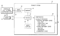
- an exhaust system 10 for use with an internal combustion engine 12 .
- the exhaust system 10 has at least one valve 14 (e.g., poppet valve) configured to control flow in the exhaust system 10 .
- the at least one valve 14 is discrete from each intake valve 13 a of the engine 12 and each exhaust valve 13 b of the engine 12 .
- a camshaft 16 is configured to operate the at least one valve 14 .
- a shaft rotator 18 secured to the camshaft 16 and under the control of a controller 20 via an electrical line 22 or wireless communication may be used to rotate the camshaft 16 continuously, discretely, or as needed to open and close or otherwise adjust the at least one valve 14 to control flow in the system 10 .
- the at least one valve 14 operated by the camshaft 16 may be used to control flow to at least one component 24 .
- the at least one component 24 may take the form of a variety of exhaust system components, a few of which are listed in FIG. 1 .
- the cam-operated valve(s) 14 may be used to control flow to one or more exhaust processors and/or a burner.
- the category of exhaust processors includes, but is not limited to, emission abatement devices (e.g., SCR catalysts and/or emissions traps such as NOx traps and/or particulate traps) and sound abatement devices (e.g., mufflers, and/or resonators).
- a combustion device may be embodied as any type of combustion device including, but not limited to, a burner and/or a fuel reformer in the form of, for example, a plasma fuel reformer and/or a catalyst.
- the cam-operated valve(s) 14 may be used to control flow to any one or more of such components arranged in any combination.
- the two valves 14 may be used to control flow of exhaust gas between the two emissions traps.
- the controller 20 may be embodied as a cylinder deactivation unit coupled electrically to the engine 12 via an electrical line 28 to control the number of operational cylinders of the engine 12 .
- the controller 20 acting through the shaft rotator 18 and the camshaft 16 , may cause the first valve 14 to open and the second valve 14 to close to direct exhaust gas to the first sound abatement device when a non-zero first number of cylinders is operation and may cause the first valve 14 to close and the second valve 14 to open to direct exhaust gas to the second sound abatement device when a non-zero second number of cylinders is operational.
- a valve 14 operated by the camshaft 16 may be used to control recirculation of exhaust gas back to the engine 14 .
- a valve 14 operated by the camshaft 16 may be used to warm the engine 14 .
- the camshaft 16 may close or only partially close the valve 14 to restrict exhaust gas flow so as to apply backpressure to the engine 14 and thereby increase its operating temperature during, for example, engine start-up and/or before “light-off” of a catalyst in the exhaust system.
- engine heat generated by such application of backpressure to the engine 14 may be used to warm an emission abatement device such as, for example, an SCR catalyst, a NOx trap, and/or a catalyzed particulate trap to its “light-off,” activation temperature to enable operation of such device(s) throughout all engine operating conditions without the use of a supplemental heat source.
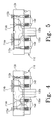
- valve assembly 100 for use in the exhaust system 10 .
- the valve assembly 100 is configured to control flow of exhaust gas from the engine 12 to first and second emissions traps configured, for example, as NOx traps 124 a, 124 b and to control flow of a regenerative agent in the form of, for example, a NOx reductant from the agent supplier 26 to the NOx traps 124 a, 124 b.
- the first and second exhaust valves 114 a, 114 b are configured to control flow of exhaust gas from the engine 12 to the traps 124 a, 124 b, respectively. More particularly, the exhaust valves 114 a, 114 are configured to control flow of exhaust gas from a first upstream passageway 130 a to first and second downstream passageways 132 a, 132 b containing the traps 124 a, 124 b, respectively.
- the first and second reductant valves 115 a, 115 b are configured to control flow of the NOx reductant from the supplier 26 to the traps 124 a, 124 b to remove NOx trapped thereby to regenerate the traps 124 a, 124 b for further use thereof. More particularly, the reductant valves 115 a, 115 b are configured to control flow of NOx reductant from a second upstream passageway 130 b to the first and second downstream passageways 132 a, 132 b containing the traps 124 a, 124 b, respectively.
- Each of the valves 114 a, 114 b, 115 a, 115 b is biased by a spring 134 to a closed position against a block 136 .
- the block 136 defines exhaust valve ports 138 a, 138 b and reductant valve ports 140 a, 140 b through which the valves 114 a, 114 b, 115 a, 115 b extend, respectively. It is within the scope of this disclosure for one or more of the valves 114 a, 114 b, 115 a, 115 b to be biased to an open position.
- a camshaft 116 is configured to operate the valves 114 a, 114 b, 115 a, 115 b in response to operation of the shaft rotator 18 .
- the camshaft 116 has a shaft 142 rotatable about an axis 143 and a plurality (e.g., four) of lobes or cams 144 secured thereto and extending radially outwardly therefrom.
- Each cam 144 is configured to pivot a rocker arm 146 associated with a respective valve 114 a, 114 b, 115 a, 115 b to open and close that valve 114 a, 114 b, 115 a, 115 b.
- a cover 148 may be used to cover one side of the valve assembly 100 to prevent dirt and debris from entering the valve assembly 100 .
- the cover 148 may be secured to the block 136 to cover the camshaft 116 , the rocker arms 146 , the springs 134 , and aportion ofthe valves 114 a, 114 b, 115 a, 115 b on the same side of the block 136 as the camshaft 116 , the rocker arms 146 , and the springs 134 .
- valves 114 a, 114 b, 115 a, 115 b are positioned in a common plane 137 to facilitate manufacture of the valve assembly 100 .
- valves 114 a, 114 b, 115 a, 115 b are used to control flow of exhaust gas and reductant to the traps 124 a, 124 b to alternate the traps 124 a, 124 b between on-line and off-line states.
- the subject trap 124 a, 124 b receives exhaust gas from the engine 12 to remove and trap NOx present in the exhaust gas while being cut off from the agent supplier 26 .
- the subject trap 124 a, 124 b receives reductant from the agent supplier 26 for reduction of the trapped NOx while being cut off from the engine 12 .
- the camshaft 116 is operated to alternate the traps 124 a, 124 b between the on-line and off-line states.
- rotation of the camshaft 116 alternately opens and closes the exhaust valves 114 a, 114 b so as to alternate advancement of exhaust to the traps 124 a, 124 b and alternately opens and closes the valves 115 a, 115 b so as to alternate advancement of the reductant to the traps 124 a, 124 b.
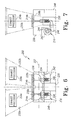
- valve assembly 200 for use in the exhaust system 10 .
- the valve assembly 200 is provided for use with a cylinder deactivation unit 20 to control flow of exhaust gas from the engine 12 to first and second exhaust processors 224 a, 224 b in response to a change in the number of operational engine cylinders from a non-zero first number (e.g., four cylinders) to a non-zero second number (e.g., eight cylinders) by the unit 20 .
- Each of the exhaust processors 224 a, 224 b may include a sound abatement device, a catalytic converter, and/or other exhaust processor.
- the illustrative valve assembly 200 has first and second exhaust valves 214 a, 214 b.
- each valve 214 a, 214 b is configured as a poppet valve.
- a camshaft 216 is configured to operate the valves 214 a, 214 b in response to operation of the shaft rotator 18 .
- the camshaft 216 has a shaft 242 rotatable about an axis 243 and a plurality (e.g., two) of lobes or cams 244 secured thereto and extending radially outwardly therefrom.
- Each cam 244 is configured to pivot a rocker arm 246 associated with a respective valve 214 a, 214 b to open and close that valve 214 a, 214 b.
- a cover 248 may be used to cover one side of the valve assembly 200 to prevent dirt and debris from entering the valve assembly 200 .
- the cover 248 may be secured to the block 236 to cover the camshaft 216 , the rocker arms 246 , the springs 234 , and a portion of the valves 214 a, 214 b on the same side of the block 236 as the camshaft 216 , the rocker arms 246 , and the springs 234 .
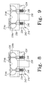
- valves 214 a, 214 b are used to control flow of exhaust gas to the processors 224 a, 224 b.
- the valve 214 a may be opened while the valve 214 b is closed in order to direct exhaust gas only to the exhaust processor 224 a, as shown in FIG. 8 .
- the valve 214 b may be opened while the valve 214 a is closed in order to direct exhaust gas only to the exhaust processor 224 b, as shown in FIG. 9 .
- both valves 214 a, 214 b may be opened, as shown in FIG. 6 .
- the valves 214 a, 214 b may be only partially closed from time to time (such as at engine start-up) so as to restrict the flow of exhaust gas and thereby increase the engine backpressure in order to elevate the exhaust gas temperature to facilitate light-off of a catalytic converter which may be included in either processor 224 a, 224 b.
- Rotation of the camshaft 216 opens and closes the exhaust valves 214 a, 214 b so as to advance exhaust to the processors 224 a, 224 b as desired.
- connection between the camshaft 16 , 116 , 216 and the valves 14 , 114 a, 114 b, 115 a , 115 b, 214 a, 214 b may be configured in a variety of ways. Use of rocker arms and/or rods extending between the cams and the rocker arms or valves may provide such a connection.
- controller 20 may be integrated into or discrete from the engine control unit of the engine 12 , any brake control unit, or other control unit onboard the vehicle.
- controller 20 may be integrated into or discrete from the hardware, software, or firmware of any such onboard control unit.
- the controller 20 may have a processor and a memory unit that is electrically coupled to the processor and has stored therein a plurality of instructions which, when executed by the processor, cause the processor to control operation of the shaft rotator 18 in response to any number of inputs representative of engine operation, emissions (e.g., present in the exhaust gas or trapped by an emissions trap), and/or sound levels, to name just a few.
Abstract
Description
- The present disclosure relates to methods and apparatus for controlling flow in exhaust systems.
- Exhaust systems are used with engines to manage exhaust gas discharged therefrom. Exhaust systems may include a number of valves to control flow in the exhaust system.
- According to an aspect of the present disclosure, there is provided an exhaust system for use with an engine. The exhaust system comprises at least one valve adapted to be located downstream from the engine to control flow in the exhaust system. The at least one valve is discrete from each intake valve of the engine and each exhaust valve of the engine. A camshaft is configured to operate the at least one valve. The at least one valve may comprise a plurality of valves operated by the camshaft. An associated method is disclosed.
- The at least one valve and the camshaft are parts of a valve assembly which may be used for a variety of purposes. For example, the valve assembly may be used to control the flow of exhaust gas, a regenerative agent, air, or other fluid of the exhaust system. Further, the valve assembly may be used with a variety of exhaust processors including, but not limited to, sound abatement devices and/or emission abatement devices embodied, for example, as any one or more of an SCR catalyst (i.e., a selective catalytic reduction catalyst) and/or an emissions traps in the form of, for example, a NOx (i.e., nitrogen oxides) trap or a particulate trap.
- The above and other features of the present disclosure will become apparent from the following description and the attached drawings.
-
FIG. 1 is a diagrammatic view of an exhaust system with at least one valve to be operated by a camshaft; -
FIG. 2 is a plan view of a valve assembly for use in the exhaust system ofFIG. 1 ; -
FIG. 3 is a side elevation view of the valve assembly ofFIG. 2 ; -
FIGS. 4 and 5 are plan views showing different operational configurations of the valve assembly ofFIG. 2 ; -
FIG. 6 is a plan view of another valve assembly for use in the exhaust system ofFIG. 1 ; -
FIG. 7 is a side elevation view of the valve assembly ofFIG. 6 ; and -
FIGS. 8 and 9 are plan views showing different operational configurations of the valve assembly ofFIG. 6 . - While the concepts of the present disclosure are susceptible to various modifications and alternative forms, specific exemplary embodiments thereof have been shown by way of example in the drawings and will herein be described in detail. It should be understood, however, that there is no intent to limit the disclosure to the particular forms disclosed, but on the contrary, the intention is to cover all modifications, equivalents, and alternatives following within the spirit and scope of the invention as defined by the appended claims.
- Referring to
FIG. 1 , there is shown anexhaust system 10 for use with aninternal combustion engine 12. Theexhaust system 10 has at least one valve 14 (e.g., poppet valve) configured to control flow in theexhaust system 10. The at least onevalve 14 is discrete from eachintake valve 13 a of theengine 12 and eachexhaust valve 13 b of theengine 12. Acamshaft 16 is configured to operate the at least onevalve 14. Ashaft rotator 18 secured to thecamshaft 16 and under the control of acontroller 20 via anelectrical line 22 or wireless communication may be used to rotate thecamshaft 16 continuously, discretely, or as needed to open and close or otherwise adjust the at least onevalve 14 to control flow in thesystem 10. - The at least one
valve 14 operated by thecamshaft 16 may be used to control flow to at least onecomponent 24. The at least onecomponent 24 may take the form of a variety of exhaust system components, a few of which are listed inFIG. 1 . For example, the cam-operated valve(s) 14 may be used to control flow to one or more exhaust processors and/or a burner. The category of exhaust processors includes, but is not limited to, emission abatement devices (e.g., SCR catalysts and/or emissions traps such as NOx traps and/or particulate traps) and sound abatement devices (e.g., mufflers, and/or resonators). A combustion device may be embodied as any type of combustion device including, but not limited to, a burner and/or a fuel reformer in the form of, for example, a plasma fuel reformer and/or a catalyst. - The cam-operated valve(s) 14 may be used to control flow to any one or more of such components arranged in any combination. For example, there may be two
valves 14 operated by thecamshaft 16 to control exhaust gas from theengine 12 to any two of the emission abatement devices, sound abatement devices, and/or combustion devices. In the case where there are two emissions traps (e.g., both NOx traps, both particulate traps, or one of each), the twovalves 14 may be used to control flow of exhaust gas between the two emissions traps. Further, there may be twomore valves 14 operated by thecamshaft 16 to control flow of an agent such as a regenerative agent (e.g., hydrocarbons, H2, CO) from anagent supplier 26 to the emissions traps such that, while one emissions trap is “on line” to trap emissions present in exhaust gas, the other emissions trap may be “off line” receiving the regenerative agent to remove emissions trapped thereby. In the case where there is an SCR catalyst, avalve 14 operated by thecamshaft 16 may be used to control flow of urea or other NOx reductant from theagent supplier 26. - In another example, there may be two
valves 14 and two sound abatement devices, onevalve 14 for each sound abatement device to control exhaust gas flow thereto in a cylinder deactivation scheme. In such a case, thecontroller 20 may be embodied as a cylinder deactivation unit coupled electrically to theengine 12 via anelectrical line 28 to control the number of operational cylinders of theengine 12. Thecontroller 20, acting through theshaft rotator 18 and thecamshaft 16, may cause thefirst valve 14 to open and thesecond valve 14 to close to direct exhaust gas to the first sound abatement device when a non-zero first number of cylinders is operation and may cause thefirst valve 14 to close and thesecond valve 14 to open to direct exhaust gas to the second sound abatement device when a non-zero second number of cylinders is operational. - In the case where there is a combustion device, there may be a
valve 14 to control flow of exhaust gas from theengine 12 to the combustion device, avalve 14 to control flow of fuel from thesupplier 26 to the combustion device, and/or avalve 14 to control flow of air from thesupplier 26 to the combustion device. Thecamshaft 16 may be used to control each of thevalves 14. - According to another example, a
valve 14 operated by thecamshaft 16 may be used to control recirculation of exhaust gas back to theengine 14. - In another example, a
valve 14 operated by thecamshaft 16 may be used to warm theengine 14. In particular, thecamshaft 16 may close or only partially close thevalve 14 to restrict exhaust gas flow so as to apply backpressure to theengine 14 and thereby increase its operating temperature during, for example, engine start-up and/or before “light-off” of a catalyst in the exhaust system. Moreover, engine heat generated by such application of backpressure to theengine 14 may be used to warm an emission abatement device such as, for example, an SCR catalyst, a NOx trap, and/or a catalyzed particulate trap to its “light-off,” activation temperature to enable operation of such device(s) throughout all engine operating conditions without the use of a supplemental heat source. - The
shaft rotator 18 may be configured in a variety of ways. For example, theshaft rotator 18 may include a solenoid valve, an air valve, and/or a motor (e.g., an electric motor) to effect rotation of thecamshaft 16. In the case of a motor, the motor may operate through a gear box and/or other connectors (e.g., belt and pulley) to rotate thecamshaft 16. - Referring to
FIGS. 2 and 3 , there is shown avalve assembly 100 for use in theexhaust system 10. Thevalve assembly 100 is configured to control flow of exhaust gas from theengine 12 to first and second emissions traps configured, for example, asNOx traps agent supplier 26 to theNOx traps - The
illustrative valve assembly 100 has first andsecond exhaust valves second reductant valves valve - The first and
second exhaust valves engine 12 to thetraps exhaust valves 114 a, 114 are configured to control flow of exhaust gas from a firstupstream passageway 130 a to first and seconddownstream passageways traps - The first and
second reductant valves supplier 26 to thetraps traps reductant valves upstream passageway 130 b to the first and seconddownstream passageways traps - Each of the
valves spring 134 to a closed position against ablock 136. Theblock 136 definesexhaust valve ports reductant valve ports valves valves - A
camshaft 116 is configured to operate thevalves shaft rotator 18. Thecamshaft 116 has ashaft 142 rotatable about anaxis 143 and a plurality (e.g., four) of lobes orcams 144 secured thereto and extending radially outwardly therefrom. Eachcam 144 is configured to pivot arocker arm 146 associated with arespective valve valve - A cover 148 may be used to cover one side of the
valve assembly 100 to prevent dirt and debris from entering thevalve assembly 100. In such a case, the cover 148 may be secured to theblock 136 to cover thecamshaft 116, therocker arms 146, thesprings 134, and aportion ofthevalves block 136 as thecamshaft 116, therocker arms 146, and thesprings 134. - Positioning the
camshaft 116, therocker arms 146, thespring 134, and the portion of thevalves block 136 facilitates the serviceability of thevalve assembly 100. Further, thevalves common plane 137 to facilitate manufacture of thevalve assembly 100. - In operation, the
valves traps traps subject trap engine 12 to remove and trap NOx present in the exhaust gas while being cut off from theagent supplier 26. In the off-line state, thesubject trap agent supplier 26 for reduction of the trapped NOx while being cut off from theengine 12. - The
camshaft 116 is operated to alternate thetraps camshaft 116 alternately opens and closes theexhaust valves traps valves traps trap 124 a in the on-line state and thetrap 124 b in the off-line state, thecamshaft 116 opens theexhaust valve 114 a and thereductant valve 115 b and closes theexhaust valve 114 b and thereductant valve 115 a, as shown inFIG. 4 . To establish thetrap 124 b in the on-line state and thetrap 124 a in the off-line state, thecamshaft 116 opens theexhaust valve 114 b and thereductant valve 115 a and closes theexhaust valve 114 a and thereductant valve 115 b, as shown inFIG. 5 . - Referring to
FIGS. 6 and 7 , there is shown avalve assembly 200 for use in theexhaust system 10. Thevalve assembly 200 is provided for use with acylinder deactivation unit 20 to control flow of exhaust gas from theengine 12 to first andsecond exhaust processors unit 20. Each of theexhaust processors - The
illustrative valve assembly 200 has first andsecond exhaust valves valve - The first and
second exhaust valves engine 12 to theprocessors exhaust valve 214 a is configured to control flow of exhaust gas from anupstream passageway 230 to a first downstream passageway 232 a containing theexhaust processor 224 a. Theexhaust valve 214 b is configured to control flow of exhaust gas from theupstream passageway 230 in communication with theengine 12 to a seconddownstream passageway 232 b containing theexhaust processor 224 b. - Each of the
valves spring 234 to a closed position against ablock 236. Theblock 236 definesexhaust valve ports valves - A
camshaft 216 is configured to operate thevalves shaft rotator 18. Thecamshaft 216 has ashaft 242 rotatable about an axis 243 and a plurality (e.g., two) of lobes orcams 244 secured thereto and extending radially outwardly therefrom. Eachcam 244 is configured to pivot arocker arm 246 associated with arespective valve valve - A
cover 248 may be used to cover one side of thevalve assembly 200 to prevent dirt and debris from entering thevalve assembly 200. In such a case, thecover 248 may be secured to theblock 236 to cover thecamshaft 216, therocker arms 246, thesprings 234, and a portion of thevalves block 236 as thecamshaft 216, therocker arms 246, and thesprings 234. - Positioning the
camshaft 216, therocker arms 246, thespring 234, and the portion of thevalves valve assembly 200. Thevalves common plane 237 to facilitate manufacture of thevalve assembly 200. - In operation, the
valves processors valve 214 a may be opened while thevalve 214 b is closed in order to direct exhaust gas only to theexhaust processor 224 a, as shown inFIG. 8 . In other engine modes (e.g., eight-cylinder mode), thevalve 214 b may be opened while thevalve 214 a is closed in order to direct exhaust gas only to theexhaust processor 224 b, as shown inFIG. 9 . In still other engine modes, it may be desirable for the exhaust gas to be directed to bothprocessors valves FIG. 6 . Thevalves processor camshaft 216 opens and closes theexhaust valves processors - It is to be understood that the connection between the
camshaft valves - It is within the scope of this disclosure to actuate any valve disclosed herein without the use of any rocker arm. It is further within the scope of this disclosure to actuate any one or more of the valves disclosed herein directly, i.e., without the use of a camshaft.
- Further, the
controller 20 may be integrated into or discrete from the engine control unit of theengine 12, any brake control unit, or other control unit onboard the vehicle. In addition, thecontroller 20 may be integrated into or discrete from the hardware, software, or firmware of any such onboard control unit. In any case, thecontroller 20 may have a processor and a memory unit that is electrically coupled to the processor and has stored therein a plurality of instructions which, when executed by the processor, cause the processor to control operation of theshaft rotator 18 in response to any number of inputs representative of engine operation, emissions (e.g., present in the exhaust gas or trapped by an emissions trap), and/or sound levels, to name just a few. - While the concepts of the present disclosure have been illustrated and described in detail in the drawings and foregoing description, such illustration and description is to be considered as exemplary and not restrictive in character, it being understood that only illustrative embodiments have been shown and described and that all changes and modifications that come within the spirit of the disclosure are desired to be protected.
- There are a plurality of advantages of the concepts of the present disclosure arising from the various features of the systems described herein. It will be noted that alternative embodiments of each of the systems of the present disclosure may not include all of the features described yet still benefit from at least some of the advantages of such features. Those of ordinary skill in the art may readily devise their own implementations of a system that incorporate one or more of the features of the present disclosure and fall within the spirit and scope of the invention as defined by the appended claims.
Claims (20)
Priority Applications (3)
| Application Number | Priority Date | Filing Date | Title |
|---|---|---|---|
| US11/332,919 US20070163243A1 (en) | 2006-01-17 | 2006-01-17 | Exhaust system with cam-operated valve assembly and associated method |
| KR1020087017345A KR20080086891A (en) | 2006-01-17 | 2007-01-10 | Exhaust system with cam-operated valve assembly and associated method |
| PCT/US2007/060309 WO2007084817A2 (en) | 2006-01-17 | 2007-01-10 | Exhaust system with cam-operated valve assembly and associated method |
Applications Claiming Priority (1)
| Application Number | Priority Date | Filing Date | Title |
|---|---|---|---|
| US11/332,919 US20070163243A1 (en) | 2006-01-17 | 2006-01-17 | Exhaust system with cam-operated valve assembly and associated method |
Publications (1)
| Publication Number | Publication Date |
|---|---|
| US20070163243A1 true US20070163243A1 (en) | 2007-07-19 |
Family
ID=38261828
Family Applications (1)
| Application Number | Title | Priority Date | Filing Date |
|---|---|---|---|
| US11/332,919 Abandoned US20070163243A1 (en) | 2006-01-17 | 2006-01-17 | Exhaust system with cam-operated valve assembly and associated method |
Country Status (3)
| Country | Link |
|---|---|
| US (1) | US20070163243A1 (en) |
| KR (1) | KR20080086891A (en) |
| WO (1) | WO2007084817A2 (en) |
Cited By (2)
| Publication number | Priority date | Publication date | Assignee | Title |
|---|---|---|---|---|
| US20080314037A1 (en) * | 2007-06-20 | 2008-12-25 | Jacobus Neels | Exhaust Gas Diverter |
| US20120186231A1 (en) * | 2009-06-02 | 2012-07-26 | Volvo Lastvagnar Ab | Exhaust gas after treatment system with temperature control |
Citations (65)
| Publication number | Priority date | Publication date | Assignee | Title |
|---|---|---|---|---|
| US3938482A (en) * | 1973-10-16 | 1976-02-17 | Toyota Jidosha Kogyo Kabushiki Kaisha | Internal combustion engine with a plurality of exhaust valves |
| US5293742A (en) * | 1991-06-27 | 1994-03-15 | Donaldson Company, Inc. | Trap apparatus with tubular filter element |
| US5355973A (en) * | 1992-06-02 | 1994-10-18 | Donaldson Company, Inc. | Muffler with catalytic converter arrangement; and method |
| US5454400A (en) * | 1992-07-14 | 1995-10-03 | Rodgers; Michael F. | Zero leakage directional control valve |
| US5655362A (en) * | 1993-09-24 | 1997-08-12 | Honda Giken Kogyo Kabushiki Kaisha | Exhaust emission control system in engine |
| US6234124B1 (en) * | 1998-11-04 | 2001-05-22 | Honda Giken Kogyo Kabushiki Kaisha | Internal combustion engine with valve rest mechanisms |
| US20020058004A1 (en) * | 1999-02-10 | 2002-05-16 | Southwest Research Institute | Method for bypassing sulfur dioxide around an aftertreatment device in an exhaust gas aftertreatment system |
| US20020175022A1 (en) * | 2000-04-26 | 2002-11-28 | Herbert Schumacher | Automotive exhaust silencer system with variable damping characteristics |
| US6755279B2 (en) * | 2000-09-11 | 2004-06-29 | Calsonic Kansei Corporation | Controllable muffler system for internal combustion engine |
| US6805093B2 (en) * | 2002-04-30 | 2004-10-19 | Mack Trucks, Inc. | Method and apparatus for combining exhaust gas recirculation and engine exhaust braking using single valve actuation |
| US20040237918A1 (en) * | 2000-09-29 | 2004-12-02 | Mendler Edward Charles | Valve control apparatus |
| US20050067219A1 (en) * | 2003-09-26 | 2005-03-31 | Albertson William C. | Method and apparatus for exhaust sound attenuation on engines with cylinder deactivation |
| US20050178612A1 (en) * | 2004-02-12 | 2005-08-18 | Nohl John P. | Electrically controlled in-muffler exhaust valve for use during cylinder deactivation |
| US20050204727A1 (en) * | 2004-03-19 | 2005-09-22 | Lewis Donald J | Cylinder deactivation for an internal combustion engine |
| US20050217241A1 (en) * | 2004-03-31 | 2005-10-06 | Honda Motor Co., Ltd. | System and method for purifying an exhaust gas |
| US20050257517A1 (en) * | 2004-05-24 | 2005-11-24 | Lavin David J | Automotive exhaust valve |
| US6971592B2 (en) * | 2002-10-17 | 2005-12-06 | Robert Bosch Gmbh | Fuel injection device for an internal combustion engine |
| US6971374B2 (en) * | 2003-07-08 | 2005-12-06 | Yamaha Marine Kabushiki Kaisha | Fuel supply system for outboard motor |
| US6971372B2 (en) * | 2002-01-15 | 2005-12-06 | Robert Bosch Gmbh | Method and device for detecting a phase of a four-stroke gasoline engine |
| US6971438B2 (en) * | 2000-12-28 | 2005-12-06 | Honda Giken Kogyo Kabushiki Kaisha | Vehicle radiator device |
| US6973918B2 (en) * | 2002-08-16 | 2005-12-13 | Robert Bosch Gmbh | Fuel injection device for an internal combustion engine |
| US6973906B2 (en) * | 2002-02-06 | 2005-12-13 | Honda Giken Kogyo Kabushiki Kaisha | Internal combustion engine provided with decompressing mechanism and method of adjusting valve lift for decompression |
| US6974315B2 (en) * | 2003-02-18 | 2005-12-13 | Harley-Davidson Motor Company Group, Inc. | Reduced friction gerotor |
| US6975935B2 (en) * | 2002-10-10 | 2005-12-13 | Robert Bosch Gmbh | Method and device for monitoring the direction of rotation of a piston engine |
| US6973912B1 (en) * | 2004-09-29 | 2005-12-13 | Keihin Corporation | Method of controlling operation of internal combustion engine |
| US6973901B2 (en) * | 2002-11-12 | 2005-12-13 | Hitachi, Ltd. | Variable valve control apparatus and method in internal combustion engine |
| US6973904B2 (en) * | 2001-07-17 | 2005-12-13 | Thyssenkrupp Automotive Ag | Variable valve-stroke controls |
| US6975934B2 (en) * | 2003-03-27 | 2005-12-13 | Honda Motor Co., Ltd. | Control system for correcting a torque variation of an engine |
| US6976462B2 (en) * | 2003-10-02 | 2005-12-20 | Jesel, Inc. | Double roller cam follower |
| US6978203B2 (en) * | 2002-05-16 | 2005-12-20 | Honda Giken Kogyo Kabushiki Kaisha | Controller for controlling element temperature of exhaust gas sensor |
| US6976638B2 (en) * | 2001-12-07 | 2005-12-20 | Robert Bosch Gmbh | Fuel injection system for an internal combustion engine |
| US6976893B2 (en) * | 2002-10-11 | 2005-12-20 | Honda Motor Co., Ltd. | Water-cooled vertical engine and outboard motor equipped therewith |
| US6976479B1 (en) * | 2004-08-10 | 2005-12-20 | Electro-Motive Diesel, Inc. | Engine with optimized engine charge air-cooling system |
| US6976464B2 (en) * | 2003-05-28 | 2005-12-20 | Dragon America Motor Technologies, Inc. | Semi-rotating valve assembly for use with an internal combustion engine |
| US6976460B2 (en) * | 2003-02-26 | 2005-12-20 | Aisin Seiki Kabushiki Kaisha | Variable valve timing control device |
| US6978204B2 (en) * | 2004-03-05 | 2005-12-20 | Ford Global Technologies, Llc | Engine system and method with cylinder deactivation |
| US6976456B2 (en) * | 2003-06-26 | 2005-12-20 | Ford Global Technologies, Llc | Connecting rod |
| US6978764B1 (en) * | 1999-10-18 | 2005-12-27 | Ford Global Technologies, Inc. | Control method for a vehicle having an engine |
| US6978616B1 (en) * | 2002-11-12 | 2005-12-27 | The United States Of America As Represented By The Secretary Of The Air Force | Hybrid piston-pulsed detonation engine |
| US6978746B2 (en) * | 2003-03-05 | 2005-12-27 | Delphi Technologies, Inc. | Method and apparatus to control a variable valve control device |
| US6978752B2 (en) * | 2004-04-23 | 2005-12-27 | General Motors Corporation | Hybrid metal-composite valve lifter guide |
| US6978750B2 (en) * | 2002-02-01 | 2005-12-27 | Nsk Ltd. | Cam follower provided with rocker arm made of sheet metal |
| US6978771B2 (en) * | 2004-04-27 | 2005-12-27 | Kabushiki Kaisha Toyota Jidoshokki | Homogeneous charge compression ignition engine and method for operating homogeneous charge compression ignition engine |
| US6978761B2 (en) * | 2003-02-26 | 2005-12-27 | Ford Global Technologies, Llc | Cylinder event based spark |
| US6978749B2 (en) * | 2003-10-27 | 2005-12-27 | Borgwarner Inc. | Means to add torsional energy to a camshaft |
| US6978769B2 (en) * | 2001-08-17 | 2005-12-27 | Volvo Technology Ab | Method of controlling the injection of fuel into a combustion chamber and a fuel injection device for performing said method |
| US6978703B2 (en) * | 2004-04-06 | 2005-12-27 | Lisle Corporation | Cam gear holding and turning wrench |
| US6981477B2 (en) * | 2004-02-25 | 2006-01-03 | Aisin Seiki Kabushiki Kaisha | Valve timing control device |
| US6981484B2 (en) * | 2001-11-14 | 2006-01-03 | Barrack Combustion Process Pty Ltd. | Internal combustion engine with divided combustion chamber |
| US6981373B2 (en) * | 2004-05-14 | 2006-01-03 | Mark Douglas Robinson | Buoyancy engine |
| US6981473B2 (en) * | 2003-02-06 | 2006-01-03 | Honda Motor Co., Ltd. | Cylinder head for an internal combustion engine |
| US6981476B2 (en) * | 2004-01-16 | 2006-01-03 | C.R.F. Societa Consortile Per Azioni | Internal combustion engine with a single camshaft which controls exhaust valves mechanically and intake valves through an electronically controlled hydraulic device |
| US6981478B2 (en) * | 2002-10-17 | 2006-01-03 | Ina-Schaeffler Kg | Electrically driven camshaft adjuster |
| US6981475B2 (en) * | 2003-03-12 | 2006-01-03 | Peugeot Citroen Automobiles Sa | Process for controlling the valves of an internal combustion engine |
| US6982619B2 (en) * | 2003-02-07 | 2006-01-03 | Robert Bosch Gmbh | Solenoid stator assembly having a reinforcement structure |
| US6981370B2 (en) * | 2002-12-03 | 2006-01-03 | Caterpillar Inc | Method and apparatus for PM filter regeneration |
| US6981653B2 (en) * | 2002-02-08 | 2006-01-03 | Robert Bosch Gmbh | Fuel injection device for an internal combustion engine |
| US6983735B2 (en) * | 2003-09-03 | 2006-01-10 | Honda Motor Co., Ltd. | Control apparatus for controlling the amount of intake air into an engine |
| US6983725B2 (en) * | 2001-10-11 | 2006-01-10 | Volvo Lastvagnar Ab | Exhaust valve mechanism in internal combustion engines |
| US6983738B2 (en) * | 2001-10-29 | 2006-01-10 | Yamaha Hatsudoki Kabushiki Kaisha | Engine control system |
| US6983734B2 (en) * | 2002-06-12 | 2006-01-10 | Toyota Jidosha Kabushiki Kaisha | Intake flow rate detecting apparatus of internal combustion engine and method of same |
| US6983730B2 (en) * | 2004-04-08 | 2006-01-10 | Kabushiki Kaisha Toyota Jidoshokki | Homogeneous charge compression ignition engine and method for operating homogeneous charge compression ignition engine |
| US6983737B2 (en) * | 2001-12-04 | 2006-01-10 | Robert Bosch Gmbh | Method, computer program and control and/or regulating device for operating an internal combustion engine |
| US6985807B2 (en) * | 2003-11-13 | 2006-01-10 | Denso Corporation | Injection quantity controller for an internal combustion engine |
| US6983646B2 (en) * | 2001-10-31 | 2006-01-10 | Yamaha Hatsudoki Kabushiki Kaisha | Atmospheric pressure detection device of four-stroke engine and method of detecting atmospheric pressure |
-
2006
- 2006-01-17 US US11/332,919 patent/US20070163243A1/en not_active Abandoned
-
2007
- 2007-01-10 KR KR1020087017345A patent/KR20080086891A/en not_active Application Discontinuation
- 2007-01-10 WO PCT/US2007/060309 patent/WO2007084817A2/en active Application Filing
Patent Citations (65)
| Publication number | Priority date | Publication date | Assignee | Title |
|---|---|---|---|---|
| US3938482A (en) * | 1973-10-16 | 1976-02-17 | Toyota Jidosha Kogyo Kabushiki Kaisha | Internal combustion engine with a plurality of exhaust valves |
| US5293742A (en) * | 1991-06-27 | 1994-03-15 | Donaldson Company, Inc. | Trap apparatus with tubular filter element |
| US5355973A (en) * | 1992-06-02 | 1994-10-18 | Donaldson Company, Inc. | Muffler with catalytic converter arrangement; and method |
| US5454400A (en) * | 1992-07-14 | 1995-10-03 | Rodgers; Michael F. | Zero leakage directional control valve |
| US5655362A (en) * | 1993-09-24 | 1997-08-12 | Honda Giken Kogyo Kabushiki Kaisha | Exhaust emission control system in engine |
| US6234124B1 (en) * | 1998-11-04 | 2001-05-22 | Honda Giken Kogyo Kabushiki Kaisha | Internal combustion engine with valve rest mechanisms |
| US20020058004A1 (en) * | 1999-02-10 | 2002-05-16 | Southwest Research Institute | Method for bypassing sulfur dioxide around an aftertreatment device in an exhaust gas aftertreatment system |
| US6978764B1 (en) * | 1999-10-18 | 2005-12-27 | Ford Global Technologies, Inc. | Control method for a vehicle having an engine |
| US20020175022A1 (en) * | 2000-04-26 | 2002-11-28 | Herbert Schumacher | Automotive exhaust silencer system with variable damping characteristics |
| US6755279B2 (en) * | 2000-09-11 | 2004-06-29 | Calsonic Kansei Corporation | Controllable muffler system for internal combustion engine |
| US20040237918A1 (en) * | 2000-09-29 | 2004-12-02 | Mendler Edward Charles | Valve control apparatus |
| US6971438B2 (en) * | 2000-12-28 | 2005-12-06 | Honda Giken Kogyo Kabushiki Kaisha | Vehicle radiator device |
| US6973904B2 (en) * | 2001-07-17 | 2005-12-13 | Thyssenkrupp Automotive Ag | Variable valve-stroke controls |
| US6978769B2 (en) * | 2001-08-17 | 2005-12-27 | Volvo Technology Ab | Method of controlling the injection of fuel into a combustion chamber and a fuel injection device for performing said method |
| US6983725B2 (en) * | 2001-10-11 | 2006-01-10 | Volvo Lastvagnar Ab | Exhaust valve mechanism in internal combustion engines |
| US6983738B2 (en) * | 2001-10-29 | 2006-01-10 | Yamaha Hatsudoki Kabushiki Kaisha | Engine control system |
| US6983646B2 (en) * | 2001-10-31 | 2006-01-10 | Yamaha Hatsudoki Kabushiki Kaisha | Atmospheric pressure detection device of four-stroke engine and method of detecting atmospheric pressure |
| US6981484B2 (en) * | 2001-11-14 | 2006-01-03 | Barrack Combustion Process Pty Ltd. | Internal combustion engine with divided combustion chamber |
| US6983737B2 (en) * | 2001-12-04 | 2006-01-10 | Robert Bosch Gmbh | Method, computer program and control and/or regulating device for operating an internal combustion engine |
| US6976638B2 (en) * | 2001-12-07 | 2005-12-20 | Robert Bosch Gmbh | Fuel injection system for an internal combustion engine |
| US6971372B2 (en) * | 2002-01-15 | 2005-12-06 | Robert Bosch Gmbh | Method and device for detecting a phase of a four-stroke gasoline engine |
| US6978750B2 (en) * | 2002-02-01 | 2005-12-27 | Nsk Ltd. | Cam follower provided with rocker arm made of sheet metal |
| US6973906B2 (en) * | 2002-02-06 | 2005-12-13 | Honda Giken Kogyo Kabushiki Kaisha | Internal combustion engine provided with decompressing mechanism and method of adjusting valve lift for decompression |
| US6981653B2 (en) * | 2002-02-08 | 2006-01-03 | Robert Bosch Gmbh | Fuel injection device for an internal combustion engine |
| US6805093B2 (en) * | 2002-04-30 | 2004-10-19 | Mack Trucks, Inc. | Method and apparatus for combining exhaust gas recirculation and engine exhaust braking using single valve actuation |
| US6978203B2 (en) * | 2002-05-16 | 2005-12-20 | Honda Giken Kogyo Kabushiki Kaisha | Controller for controlling element temperature of exhaust gas sensor |
| US6983734B2 (en) * | 2002-06-12 | 2006-01-10 | Toyota Jidosha Kabushiki Kaisha | Intake flow rate detecting apparatus of internal combustion engine and method of same |
| US6973918B2 (en) * | 2002-08-16 | 2005-12-13 | Robert Bosch Gmbh | Fuel injection device for an internal combustion engine |
| US6975935B2 (en) * | 2002-10-10 | 2005-12-13 | Robert Bosch Gmbh | Method and device for monitoring the direction of rotation of a piston engine |
| US6976893B2 (en) * | 2002-10-11 | 2005-12-20 | Honda Motor Co., Ltd. | Water-cooled vertical engine and outboard motor equipped therewith |
| US6971592B2 (en) * | 2002-10-17 | 2005-12-06 | Robert Bosch Gmbh | Fuel injection device for an internal combustion engine |
| US6981478B2 (en) * | 2002-10-17 | 2006-01-03 | Ina-Schaeffler Kg | Electrically driven camshaft adjuster |
| US6973901B2 (en) * | 2002-11-12 | 2005-12-13 | Hitachi, Ltd. | Variable valve control apparatus and method in internal combustion engine |
| US6978616B1 (en) * | 2002-11-12 | 2005-12-27 | The United States Of America As Represented By The Secretary Of The Air Force | Hybrid piston-pulsed detonation engine |
| US6981370B2 (en) * | 2002-12-03 | 2006-01-03 | Caterpillar Inc | Method and apparatus for PM filter regeneration |
| US6981473B2 (en) * | 2003-02-06 | 2006-01-03 | Honda Motor Co., Ltd. | Cylinder head for an internal combustion engine |
| US6982619B2 (en) * | 2003-02-07 | 2006-01-03 | Robert Bosch Gmbh | Solenoid stator assembly having a reinforcement structure |
| US6974315B2 (en) * | 2003-02-18 | 2005-12-13 | Harley-Davidson Motor Company Group, Inc. | Reduced friction gerotor |
| US6976460B2 (en) * | 2003-02-26 | 2005-12-20 | Aisin Seiki Kabushiki Kaisha | Variable valve timing control device |
| US6978761B2 (en) * | 2003-02-26 | 2005-12-27 | Ford Global Technologies, Llc | Cylinder event based spark |
| US6978746B2 (en) * | 2003-03-05 | 2005-12-27 | Delphi Technologies, Inc. | Method and apparatus to control a variable valve control device |
| US6981475B2 (en) * | 2003-03-12 | 2006-01-03 | Peugeot Citroen Automobiles Sa | Process for controlling the valves of an internal combustion engine |
| US6975934B2 (en) * | 2003-03-27 | 2005-12-13 | Honda Motor Co., Ltd. | Control system for correcting a torque variation of an engine |
| US6976464B2 (en) * | 2003-05-28 | 2005-12-20 | Dragon America Motor Technologies, Inc. | Semi-rotating valve assembly for use with an internal combustion engine |
| US6976456B2 (en) * | 2003-06-26 | 2005-12-20 | Ford Global Technologies, Llc | Connecting rod |
| US6971374B2 (en) * | 2003-07-08 | 2005-12-06 | Yamaha Marine Kabushiki Kaisha | Fuel supply system for outboard motor |
| US6983735B2 (en) * | 2003-09-03 | 2006-01-10 | Honda Motor Co., Ltd. | Control apparatus for controlling the amount of intake air into an engine |
| US20050067219A1 (en) * | 2003-09-26 | 2005-03-31 | Albertson William C. | Method and apparatus for exhaust sound attenuation on engines with cylinder deactivation |
| US6976462B2 (en) * | 2003-10-02 | 2005-12-20 | Jesel, Inc. | Double roller cam follower |
| US6978749B2 (en) * | 2003-10-27 | 2005-12-27 | Borgwarner Inc. | Means to add torsional energy to a camshaft |
| US6985807B2 (en) * | 2003-11-13 | 2006-01-10 | Denso Corporation | Injection quantity controller for an internal combustion engine |
| US6981476B2 (en) * | 2004-01-16 | 2006-01-03 | C.R.F. Societa Consortile Per Azioni | Internal combustion engine with a single camshaft which controls exhaust valves mechanically and intake valves through an electronically controlled hydraulic device |
| US20050178612A1 (en) * | 2004-02-12 | 2005-08-18 | Nohl John P. | Electrically controlled in-muffler exhaust valve for use during cylinder deactivation |
| US6981477B2 (en) * | 2004-02-25 | 2006-01-03 | Aisin Seiki Kabushiki Kaisha | Valve timing control device |
| US6978204B2 (en) * | 2004-03-05 | 2005-12-20 | Ford Global Technologies, Llc | Engine system and method with cylinder deactivation |
| US20050204727A1 (en) * | 2004-03-19 | 2005-09-22 | Lewis Donald J | Cylinder deactivation for an internal combustion engine |
| US20050217241A1 (en) * | 2004-03-31 | 2005-10-06 | Honda Motor Co., Ltd. | System and method for purifying an exhaust gas |
| US6978703B2 (en) * | 2004-04-06 | 2005-12-27 | Lisle Corporation | Cam gear holding and turning wrench |
| US6983730B2 (en) * | 2004-04-08 | 2006-01-10 | Kabushiki Kaisha Toyota Jidoshokki | Homogeneous charge compression ignition engine and method for operating homogeneous charge compression ignition engine |
| US6978752B2 (en) * | 2004-04-23 | 2005-12-27 | General Motors Corporation | Hybrid metal-composite valve lifter guide |
| US6978771B2 (en) * | 2004-04-27 | 2005-12-27 | Kabushiki Kaisha Toyota Jidoshokki | Homogeneous charge compression ignition engine and method for operating homogeneous charge compression ignition engine |
| US6981373B2 (en) * | 2004-05-14 | 2006-01-03 | Mark Douglas Robinson | Buoyancy engine |
| US20050257517A1 (en) * | 2004-05-24 | 2005-11-24 | Lavin David J | Automotive exhaust valve |
| US6976479B1 (en) * | 2004-08-10 | 2005-12-20 | Electro-Motive Diesel, Inc. | Engine with optimized engine charge air-cooling system |
| US6973912B1 (en) * | 2004-09-29 | 2005-12-13 | Keihin Corporation | Method of controlling operation of internal combustion engine |
Cited By (3)
| Publication number | Priority date | Publication date | Assignee | Title |
|---|---|---|---|---|
| US20080314037A1 (en) * | 2007-06-20 | 2008-12-25 | Jacobus Neels | Exhaust Gas Diverter |
| US20120186231A1 (en) * | 2009-06-02 | 2012-07-26 | Volvo Lastvagnar Ab | Exhaust gas after treatment system with temperature control |
| US20140311127A1 (en) * | 2009-06-02 | 2014-10-23 | Volvo Lastvagnar Ab | Exhaust gas after treatment system with temperature control |
Also Published As
| Publication number | Publication date |
|---|---|
| WO2007084817A2 (en) | 2007-07-26 |
| KR20080086891A (en) | 2008-09-26 |
| WO2007084817A3 (en) | 2007-12-06 |
Similar Documents
| Publication | Publication Date | Title |
|---|---|---|
| US10883453B2 (en) | Engine system | |
| US6164065A (en) | After treatment system for a variable displacement engine | |
| US20080295499A1 (en) | Exhaust system utilizing a low-temperature oxidation catalyst | |
| US6557341B2 (en) | Exhaust system of an internal combustion engine | |
| US9541010B2 (en) | Engine including camshaft with lobe features for internal exhaust gas recirculation | |
| EP2933452B1 (en) | Aftertreatment thermal management strategies for internal combustion engines having multiple cylinder banks | |
| US11073113B2 (en) | Exhaust manifold | |
| US20070163243A1 (en) | Exhaust system with cam-operated valve assembly and associated method | |
| CN113167159A (en) | Post-processing system | |
| JP2008240552A (en) | Exhaust emission control device for internal combustion engine | |
| CN111287872B (en) | Intake manifold and engine system | |
| GB2501923A (en) | Method of controlling an internal combustion engine | |
| JP2009008022A (en) | Exhaust throttle valve | |
| JP2002322909A (en) | Engine exhaust emission processing method and the device | |
| US20120067331A1 (en) | Controlling engine braking loads using cat regeneration system (CRS) | |
| US11002171B2 (en) | Exhaust heat recovery and acoustic valve with exhaust gas recirculation features | |
| US10876450B2 (en) | Splitflow catalyst system | |
| US11203954B2 (en) | Pre-lubrication and skip fire operations during engine cranking | |
| JP5316712B2 (en) | Control device for internal combustion engine | |
| JP2021131086A (en) | Exhaust emission control device | |
| GB2505511A (en) | A catalyst converter | |
| JP2021050614A (en) | Exhaust emission control device | |
| JP2021131038A (en) | Exhaust system structure | |
| JP4085752B2 (en) | Exhaust pressure control device | |
| KR20120058152A (en) | Exhaust gas purification system of vehicle |
Legal Events
| Date | Code | Title | Description |
|---|---|---|---|
| AS | Assignment |
Owner name: ARVIN TECHNOLOGIES, INC., MICHIGAN Free format text: ASSIGNMENT OF ASSIGNORS INTEREST;ASSIGNORS:COKER, ADAM;NOHL, JOHN;REEL/FRAME:017464/0198;SIGNING DATES FROM 20060105 TO 20060113 |
|
| AS | Assignment |
Owner name: ET US HOLDINGS LLC,DELAWARE Free format text: ASSIGNMENT OF ASSIGNORS INTEREST;ASSIGNOR:ARVIN TECHNOLOGIES, INC.;REEL/FRAME:019378/0744 Effective date: 20070516 Owner name: ET US HOLDINGS LLC, DELAWARE Free format text: ASSIGNMENT OF ASSIGNORS INTEREST;ASSIGNOR:ARVIN TECHNOLOGIES, INC.;REEL/FRAME:019378/0744 Effective date: 20070516 |
|
| AS | Assignment |
Owner name: THE CIT GROUP/BUSINESS CREDIT, INC.,ILLINOIS Free format text: SECURITY AGREEMENT;ASSIGNOR:ET US HOLDINGS LLC;REEL/FRAME:019353/0736 Effective date: 20070525 Owner name: THE CIT GROUP/BUSINESS CREDIT, INC., ILLINOIS Free format text: SECURITY AGREEMENT;ASSIGNOR:ET US HOLDINGS LLC;REEL/FRAME:019353/0736 Effective date: 20070525 |
|
| AS | Assignment |
Owner name: EMCON TECHNOLOGIES LLC (FORMERLY KNOWN AS ET US HO Free format text: RELEASE BY SECURED PARTY;ASSIGNOR:CIT GROUP/BUSINESS CREDIT, INC.;REEL/FRAME:023957/0741 Effective date: 20100208 |
|
| STCB | Information on status: application discontinuation |
Free format text: ABANDONED -- FAILURE TO RESPOND TO AN OFFICE ACTION |