US20080042657A1 - Multi-scanner device having a detachable outlet tester - Google Patents
Multi-scanner device having a detachable outlet tester Download PDFInfo
- Publication number
- US20080042657A1 US20080042657A1 US11/840,616 US84061607A US2008042657A1 US 20080042657 A1 US20080042657 A1 US 20080042657A1 US 84061607 A US84061607 A US 84061607A US 2008042657 A1 US2008042657 A1 US 2008042657A1
- Authority
- US
- United States
- Prior art keywords
- outlet
- detection unit
- scanner device
- tester
- circuitry
- Prior art date
- Legal status (The legal status is an assumption and is not a legal conclusion. Google has not performed a legal analysis and makes no representation as to the accuracy of the status listed.)
- Granted
Links
Images


Classifications
-
- G—PHYSICS
- G01—MEASURING; TESTING
- G01R—MEASURING ELECTRIC VARIABLES; MEASURING MAGNETIC VARIABLES
- G01R31/00—Arrangements for testing electric properties; Arrangements for locating electric faults; Arrangements for electrical testing characterised by what is being tested not provided for elsewhere
- G01R31/50—Testing of electric apparatus, lines, cables or components for short-circuits, continuity, leakage current or incorrect line connections
- G01R31/66—Testing of connections, e.g. of plugs or non-disconnectable joints
- G01R31/68—Testing of releasable connections, e.g. of terminals mounted on a printed circuit board
- G01R31/69—Testing of releasable connections, e.g. of terminals mounted on a printed circuit board of terminals at the end of a cable or a wire harness; of plugs; of sockets, e.g. wall sockets or power sockets in appliances
Definitions
- Wall sensors and scanners such as stud finders
- stud finders are well-known and commonly used by tradesmen and do-it-yourselfers in construction projects to locate objects located below the surface of a wall.
- One type of stud finder is a single mode electronic stud finder, which typically includes a capacitor for detecting changes in the capacitance as the stud finder moves across the surface of the wall. A change in capacitance indicates that the dielectric constant of the surface has changed due to the presence of an object behind the surface of the wall.
- a stud finder might include separate circuitry for detecting metal behind a wallboard and for detecting an AC voltage behind a wallboard to determine whether the wall has a live wire behind it.
- An AC voltage detector may alert the user to the location of electrical wiring in the wall and could prevent the user from cutting into the wire.
- an AC voltage detector could aid the user in finding the wire if the user is performing electrical work.
- Electrical outlet testers are another commonly used tool for electrical work. These devices are typically self-contained, and designed to be plugged into a standard electrical outlet having hot, neutral, and ground connections to determine whether the outlet is properly wired. These devices allow the wiring of an electrical outlet to be verified easily, without the need for meters or other devices.
- Certain construction projects involving electrical work require both a detection unit and an electrical outlet tester. For example, installing a new outlet requires that the tradesman determine the location of existing electrical outlets and wall studs, wire the new outlet, and ensure that the outlet is correctly wired. If the outlet includes a ground fault circuit interrupter, it requires testing. However, the need for two separate tools creates a problem because the user needs to (1) buy two separate tools, and (2) actually find each tool when he or she wants to use them.
- the present invention combines a detection unit and an outlet tester for convenient use and easy storage.
- the plug on the outlet tester can be inserted into a non-functional socket located on the detection unit to form a multi-scanner device with a detachable outlet tester.
- the user scans the surface of the wall with the detection unit, which may have multiple scanning functions, to locate studs or electrical wiring. If the user needs an outlet tester, then he or she simply detaches the outlet tester from the detection unit. Then, once the outlet has been tested, the user can reattach the outlet tester to the detection unit, reforming the multi-scanner device.
- FIG. 1 is a perspective view of a multi-scanner device shown when separated into its detection unit and outlet test components;
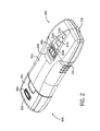
- FIG. 2 is a perspective view of the multi-scanner device in which the outlet tester has been attached to the detection unit;
- FIG. 3 is a front view of the multi-scanner device shown in FIG. 3 ;
- FIG. 4 is a back view of the multi-scanner device shown in FIG. 3 .
- a multi-scanner device 100 includes a detection unit 200 and an outlet tester 300 .
- the detection unit 200 includes circuitry for providing wood stud detection, metal detection, and a non-contact AC voltage detection as described below.
- the outlet tester 300 provides an outlet wiring test and a ground fault circuit interrupter test.
- the detection unit 200 has an interface that can be, as shown here, a socket 202 , and the outlet tester 300 has a mating plug 302 . When the outlet tester 300 is not in use, the plug 302 can be inserted in the socket 202 for easy storage of the outlet tester 300 .
- the detection unit 200 has a housing 204 in which the circuitry for performing the available scanning modes is encased.
- a scan mode switch 206 is located on the front face of the detection unit 200 .
- the scan mode switch 206 permits the user of the detection unit 200 to toggle among the available scanning modes. In FIG. 1 the scan mode switch 206 is a three-way sliding switch.
- An LED switch selection indicator 208 is located on the front face of the detection unit 200 below the scan mode switch 206 .
- the LED switch selection indicator 208 uses LED lights to display which of the available scanning modes the user has selected with the scan mode switch 206 .
- the surface of the on-off switch 210 and the right side of the unit have ridged grips 212 which make the detection unit 200 easy to hold and unlikely to slip out of the user's hands.
- a set of LED position indicators 214 a - d located on the front face of the detection unit 200 , indicate when the detection unit 200 has detected an object behind the scanned surface.
- a tip 216 shown in FIG. 2 , is located on the nose of the detection unit 200 for marking a location on a wall.
- the user selects the scanning mode using the scan mode switch 206 , holds the detection unit 200 up to a wallboard, presses and holds the on-off switch 210 , and moves the detection unit 200 across the wall.
- the circuitry of the detection unit 200 detects the selected material or AC voltage of the selected mode behind the wallboard
- the LED position indicators 214 a - d begin to illuminate.
- An LED position indicator 214 a first illuminates when the circuitry weakly detects the selected material or AC voltage. As the user continues to move the detection unit 200 across the wallboard, if the circuitry detects an even stronger presence of the selected material or AC voltage, then the LED position indicator 214 b will also illuminate.
- LED position indicator 214 c illuminating
- LED position indicator 214 d illuminating
- the user will be near the center of the detected object, such as a wood stud.
- the tip 216 might then be used to mark the location on the wall by making an indentation.
- the tip 216 may also function as a non-contact AC voltage detector antenna.
- the detection unit 200 may be capable of one or more scanning functions including, but not limited to, wood stud detector, metal detector, and non-contact AC voltage detector.
- the scan mode switch 206 is not required and is only preferable if the detection unit 200 is capable of performing more than one scanning function.
- the circuitry for each scanning function in the housing 204 may operate independently of each other or share common elements.
- the circuitry may perform multiple scanning functions simultaneously, eliminating the need for the scan mode switch 206 . Circuitry for performing these functions are well known and not in need of a detailed description herein.
- FIG. 1 illustrates geometry compatible with a Type B three-pin plug and socket, typically used in the United States for 115 volt, 60 hertz power supplies
- any type of socket and plug combination might be used to connect the detection unit 200 and the outlet tester 300 .
- the detection unit 200 and the outlet tester 300 might also be connected using an interface or attachment means in addition to the plug 302 and socket 202 .
- different types of plug/socket combinations may be used for different voltage levels, or to match the plug/socket combinations used in a particular region.
- the plug 302 may simply fit into a cavity in the housing 204 , and the detection unit 200 and the outlet tester 300 are in some other way adapted to be selectively connected together.
- Various other types of connectors for coupling the outlet tester 300 to the detection unit 200 including hook and loop fasteners, sliding attachment members, threaded fasteners, and other types of devices can also be used.
- a snap fit connection can be used.
- the presence of a socket 202 on the detection unit 200 should not be considered limiting.
- the LED switch selection indicator 208 and the LED position indicators 214 a - d might be complemented or replaced by other forms of audible or visual alarms.
- the detection unit 200 may also provide a variable or multi-tone audible alarm indicating the detection strength.
- the detection device instead of utilizing LED lights, might have an alternate form of visual feedback, such as a liquid crystal display, or provide aural feedback, such as beeps or other sounds, through a speaker system provided in the device and which is transmitted through holes in the housing of the device (not shown).
- the outlet tester 300 has circuitry for performing its electrical outlet testing functions inside a housing 304 .
- the plug 302 of the outlet tester 300 is placed into an electrical socket, and the LEDs 308 are activated to illustrate either that the wiring is good, or a fault in the wiring, depending on the pattern.
- the disclosure of Virgilio U.S. Pat. No. 5,625,285, assigned to A.W. Sperry Instruments, which describe the operation and feedback provided by such an outlet tester, is hereby incorporated by reference. Although a series of LEDs are shown here for providing verification of wiring, an LCD display including testing result and wiring correction information can also be provided instead of or in addition to the LEDs 308 .
- an outlet switch 306 may be provided to activate a GFCI test from the outlet tester 300 .
- the user activates the switch 306 , which shorts out the wall socket to activate and verify the circuit breaker that is built into the GFCI-enabled wall socket.
- the outlet tester 300 can also be provided with an arc-fault tester function.
- the outlet tester 300 may be capable of one or more electrical socket testing functions including, but not limited to, an outlet faulty wiring tester and a ground fault circuit interrupter tester.
- the outlet mode switch 306 is not required and is only preferable if the outlet tester 300 has circuitry for performing more than one electrical socket testing function.
- the circuitry for performing each of the outlet testing functions in the housing 304 may operate independently of each other or share common elements.
- FIG. 2 provides a perspective view and FIG. 3 provides a top view of the multi-scanner device 100 after the detection unit 200 and the outlet tester 300 have been connected by inserting the plug 302 into the socket 202 .
- FIG. 2 clearly shows the tip 216 which may be used to mark a wall or perform as a non-contact AC voltage detector.
- FIG. 3 clearly shows the on-off switch 210 which the user presses to engage the selected mode.
- FIG. 4 provides a back view of the multi-scanner device 100 after the detection unit 200 and the outlet tester 300 have been attached by inserting the plug 302 into the socket 202 .
- a battery cover 218 holds the batteries in the detection unit 200 .
Abstract
Description
- This application claims the benefit of U.S. Provisional Patent Application No. 60/822,701 filed Aug. 17, 2006.
- Not Applicable
- Wall sensors and scanners, such as stud finders, are well-known and commonly used by tradesmen and do-it-yourselfers in construction projects to locate objects located below the surface of a wall. One type of stud finder is a single mode electronic stud finder, which typically includes a capacitor for detecting changes in the capacitance as the stud finder moves across the surface of the wall. A change in capacitance indicates that the dielectric constant of the surface has changed due to the presence of an object behind the surface of the wall.
- In addition to single mode wall scanners, multifunction detection units have been developed which can be toggled between various modes of detection. For example, in addition to the circuitry described above, a stud finder might include separate circuitry for detecting metal behind a wallboard and for detecting an AC voltage behind a wallboard to determine whether the wall has a live wire behind it. An AC voltage detector may alert the user to the location of electrical wiring in the wall and could prevent the user from cutting into the wire. Alternatively, an AC voltage detector could aid the user in finding the wire if the user is performing electrical work.
- Electrical outlet testers are another commonly used tool for electrical work. These devices are typically self-contained, and designed to be plugged into a standard electrical outlet having hot, neutral, and ground connections to determine whether the outlet is properly wired. These devices allow the wiring of an electrical outlet to be verified easily, without the need for meters or other devices.
- Certain construction projects involving electrical work require both a detection unit and an electrical outlet tester. For example, installing a new outlet requires that the tradesman determine the location of existing electrical outlets and wall studs, wire the new outlet, and ensure that the outlet is correctly wired. If the outlet includes a ground fault circuit interrupter, it requires testing. However, the need for two separate tools creates a problem because the user needs to (1) buy two separate tools, and (2) actually find each tool when he or she wants to use them.
- The present invention combines a detection unit and an outlet tester for convenient use and easy storage. The plug on the outlet tester can be inserted into a non-functional socket located on the detection unit to form a multi-scanner device with a detachable outlet tester.
- In typical use, the user scans the surface of the wall with the detection unit, which may have multiple scanning functions, to locate studs or electrical wiring. If the user needs an outlet tester, then he or she simply detaches the outlet tester from the detection unit. Then, once the outlet has been tested, the user can reattach the outlet tester to the detection unit, reforming the multi-scanner device.
- These and other features and advantages of the invention will appear in the detailed description which follows. In the description, reference is made to the accompanying drawings which illustrate a preferred embodiment of this invention.
-
FIG. 1 is a perspective view of a multi-scanner device shown when separated into its detection unit and outlet test components; -
FIG. 2 is a perspective view of the multi-scanner device in which the outlet tester has been attached to the detection unit; -
FIG. 3 is a front view of the multi-scanner device shown inFIG. 3 ; and -
FIG. 4 is a back view of the multi-scanner device shown inFIG. 3 . - Referring now to
FIG. 1 , amulti-scanner device 100 includes adetection unit 200 and anoutlet tester 300. Thedetection unit 200 includes circuitry for providing wood stud detection, metal detection, and a non-contact AC voltage detection as described below. Theoutlet tester 300 provides an outlet wiring test and a ground fault circuit interrupter test. Thedetection unit 200 has an interface that can be, as shown here, asocket 202, and theoutlet tester 300 has amating plug 302. When theoutlet tester 300 is not in use, theplug 302 can be inserted in thesocket 202 for easy storage of theoutlet tester 300. - The
detection unit 200 has ahousing 204 in which the circuitry for performing the available scanning modes is encased. Ascan mode switch 206 is located on the front face of thedetection unit 200. Thescan mode switch 206 permits the user of thedetection unit 200 to toggle among the available scanning modes. InFIG. 1 thescan mode switch 206 is a three-way sliding switch. An LEDswitch selection indicator 208 is located on the front face of thedetection unit 200 below thescan mode switch 206. The LEDswitch selection indicator 208 uses LED lights to display which of the available scanning modes the user has selected with thescan mode switch 206. - The user presses an on-off
switch 210 located on the left side of thedetection unit 200, which is shown inFIG. 3 , to activate the circuitry of thedetection unit 200 and perform the selected mode of operation. The surface of the on-offswitch 210 and the right side of the unit haveridged grips 212 which make thedetection unit 200 easy to hold and unlikely to slip out of the user's hands. A set of LED position indicators 214 a-d, located on the front face of thedetection unit 200, indicate when thedetection unit 200 has detected an object behind the scanned surface. Atip 216, shown inFIG. 2 , is located on the nose of thedetection unit 200 for marking a location on a wall. - In typical use, the user selects the scanning mode using the
scan mode switch 206, holds thedetection unit 200 up to a wallboard, presses and holds the on-off switch 210, and moves thedetection unit 200 across the wall. When the circuitry of thedetection unit 200 detects the selected material or AC voltage of the selected mode behind the wallboard, the LED position indicators 214 a-d begin to illuminate. AnLED position indicator 214 a first illuminates when the circuitry weakly detects the selected material or AC voltage. As the user continues to move thedetection unit 200 across the wallboard, if the circuitry detects an even stronger presence of the selected material or AC voltage, then theLED position indicator 214 b will also illuminate. Further increases in signal will result inLED position indicator 214 c illuminating, andLED position indicator 214 d illuminating. In one possible configuration of thedetection unit 200, when all of the LED position indicators 214 a-d are lit, the user will be near the center of the detected object, such as a wood stud. Thetip 216 might then be used to mark the location on the wall by making an indentation. Thetip 216 may also function as a non-contact AC voltage detector antenna. - It should be appreciated that the
detection unit 200 may be capable of one or more scanning functions including, but not limited to, wood stud detector, metal detector, and non-contact AC voltage detector. Thescan mode switch 206 is not required and is only preferable if thedetection unit 200 is capable of performing more than one scanning function. Additionally, the circuitry for each scanning function in thehousing 204 may operate independently of each other or share common elements. Moreover, in some applications, the circuitry may perform multiple scanning functions simultaneously, eliminating the need for thescan mode switch 206. Circuitry for performing these functions are well known and not in need of a detailed description herein. - It should be further appreciated that although
FIG. 1 illustrates geometry compatible with a Type B three-pin plug and socket, typically used in the United States for 115 volt, 60 hertz power supplies, any type of socket and plug combination might be used to connect thedetection unit 200 and theoutlet tester 300. However, thedetection unit 200 and theoutlet tester 300 might also be connected using an interface or attachment means in addition to theplug 302 andsocket 202. For example, different types of plug/socket combinations may be used for different voltage levels, or to match the plug/socket combinations used in a particular region. Additionally, theplug 302 may simply fit into a cavity in thehousing 204, and thedetection unit 200 and theoutlet tester 300 are in some other way adapted to be selectively connected together. Various other types of connectors for coupling theoutlet tester 300 to thedetection unit 200, including hook and loop fasteners, sliding attachment members, threaded fasteners, and other types of devices can also be used. In addition, irrespective of the type of connection used, a snap fit connection can be used. Thus, the presence of asocket 202 on thedetection unit 200 should not be considered limiting. - It should be further appreciated that the LED
switch selection indicator 208 and the LED position indicators 214 a-d might be complemented or replaced by other forms of audible or visual alarms. For example, in addition to the LED position indicators 214 a-d, thedetection unit 200 may also provide a variable or multi-tone audible alarm indicating the detection strength. Likewise, instead of utilizing LED lights, the detection device might have an alternate form of visual feedback, such as a liquid crystal display, or provide aural feedback, such as beeps or other sounds, through a speaker system provided in the device and which is transmitted through holes in the housing of the device (not shown). - The
outlet tester 300 has circuitry for performing its electrical outlet testing functions inside ahousing 304. In typical use, theplug 302 of theoutlet tester 300 is placed into an electrical socket, and theLEDs 308 are activated to illustrate either that the wiring is good, or a fault in the wiring, depending on the pattern. The disclosure of Virgilio U.S. Pat. No. 5,625,285, assigned to A.W. Sperry Instruments, which describe the operation and feedback provided by such an outlet tester, is hereby incorporated by reference. Although a series of LEDs are shown here for providing verification of wiring, an LCD display including testing result and wiring correction information can also be provided instead of or in addition to theLEDs 308. - In addition to the wiring test and verification, an
outlet switch 306 may be provided to activate a GFCI test from theoutlet tester 300. When testing a GFCI-enabled wall circuit, the user activates theswitch 306, which shorts out the wall socket to activate and verify the circuit breaker that is built into the GFCI-enabled wall socket. In alternative embodiments, theoutlet tester 300 can also be provided with an arc-fault tester function. - It should be appreciated that the
outlet tester 300 may be capable of one or more electrical socket testing functions including, but not limited to, an outlet faulty wiring tester and a ground fault circuit interrupter tester. Thus, theoutlet mode switch 306 is not required and is only preferable if theoutlet tester 300 has circuitry for performing more than one electrical socket testing function. The circuitry for performing each of the outlet testing functions in thehousing 304 may operate independently of each other or share common elements. -
FIG. 2 provides a perspective view andFIG. 3 provides a top view of themulti-scanner device 100 after thedetection unit 200 and theoutlet tester 300 have been connected by inserting theplug 302 into thesocket 202.FIG. 2 clearly shows thetip 216 which may be used to mark a wall or perform as a non-contact AC voltage detector.FIG. 3 clearly shows the on-off switch 210 which the user presses to engage the selected mode. -
FIG. 4 provides a back view of themulti-scanner device 100 after thedetection unit 200 and theoutlet tester 300 have been attached by inserting theplug 302 into thesocket 202. Abattery cover 218 holds the batteries in thedetection unit 200. - It is specifically intended that the present invention not be limited to the embodiments and illustrations contained herein, but include modified forms of those embodiments including portions of the embodiments and combinations of elements of different embodiments as come within the scope of the following claims.
Claims (14)
Priority Applications (3)
| Application Number | Priority Date | Filing Date | Title |
|---|---|---|---|
| US11/840,616 US7633282B2 (en) | 2006-08-17 | 2007-08-17 | Multi-scanner device having a detachable outlet tester |
| US12/624,129 US7928717B1 (en) | 2006-08-17 | 2009-11-23 | Multi-scanner device having a detachable outlet tester |
| US13/070,592 US8085032B2 (en) | 2006-08-17 | 2011-03-24 | Multi-scanner device having a detachable outlet tester |
Applications Claiming Priority (2)
| Application Number | Priority Date | Filing Date | Title |
|---|---|---|---|
| US82270106P | 2006-08-17 | 2006-08-17 | |
| US11/840,616 US7633282B2 (en) | 2006-08-17 | 2007-08-17 | Multi-scanner device having a detachable outlet tester |
Related Child Applications (1)
| Application Number | Title | Priority Date | Filing Date |
|---|---|---|---|
| US12/624,129 Continuation US7928717B1 (en) | 2006-08-17 | 2009-11-23 | Multi-scanner device having a detachable outlet tester |
Publications (2)
| Publication Number | Publication Date |
|---|---|
| US20080042657A1 true US20080042657A1 (en) | 2008-02-21 |
| US7633282B2 US7633282B2 (en) | 2009-12-15 |
Family
ID=39100799
Family Applications (3)
| Application Number | Title | Priority Date | Filing Date |
|---|---|---|---|
| US11/840,616 Active 2028-02-02 US7633282B2 (en) | 2006-08-17 | 2007-08-17 | Multi-scanner device having a detachable outlet tester |
| US12/624,129 Expired - Fee Related US7928717B1 (en) | 2006-08-17 | 2009-11-23 | Multi-scanner device having a detachable outlet tester |
| US13/070,592 Expired - Fee Related US8085032B2 (en) | 2006-08-17 | 2011-03-24 | Multi-scanner device having a detachable outlet tester |
Family Applications After (2)
| Application Number | Title | Priority Date | Filing Date |
|---|---|---|---|
| US12/624,129 Expired - Fee Related US7928717B1 (en) | 2006-08-17 | 2009-11-23 | Multi-scanner device having a detachable outlet tester |
| US13/070,592 Expired - Fee Related US8085032B2 (en) | 2006-08-17 | 2011-03-24 | Multi-scanner device having a detachable outlet tester |
Country Status (1)
| Country | Link |
|---|---|
| US (3) | US7633282B2 (en) |
Cited By (18)
| Publication number | Priority date | Publication date | Assignee | Title |
|---|---|---|---|---|
| US8058879B1 (en) | 2009-01-06 | 2011-11-15 | Atherton John C | Voltage indicating coupling for metal conduit systems |
| US8193802B2 (en) | 2008-04-09 | 2012-06-05 | Milwaukee Electric Tool Corporation | Slidably attachable non-contact voltage detector |
| USD684067S1 (en) * | 2012-02-15 | 2013-06-11 | Certusview Technologies, Llc | Modular marking device |
| AU2009234158B2 (en) * | 2008-04-09 | 2013-12-19 | Milwaukee Electric Tool Corporation | Test and measurement device with a pistol-grip handle |
| USD726185S1 (en) * | 2013-05-23 | 2015-04-07 | Bluebird Inc. | Data scan device |
| US20160327599A1 (en) * | 2015-05-05 | 2016-11-10 | Power Products, Llc | Combination test device |
| US20160334455A1 (en) * | 2015-05-11 | 2016-11-17 | Kyocera Document Solutions Inc. | Image forming apparatus and method of controlling image forming apparatus |
| US10429431B2 (en) | 2015-05-05 | 2019-10-01 | ECM Industries | Codeless receptacle tester |
| USD876436S1 (en) * | 2017-05-31 | 2020-02-25 | Symbol Technologies, Llc | Mobile device accessory |
| USD907634S1 (en) * | 2016-08-01 | 2021-01-12 | Hand Held Products, Inc. | Optical scanner |
| USD917115S1 (en) * | 2020-09-27 | 2021-04-20 | Yijun Tang | Dog trainer |
| US20210223331A1 (en) * | 2020-01-17 | 2021-07-22 | Brunswick Corporation | RV Electrical Outlet Tester |
| CN113985321A (en) * | 2021-12-27 | 2022-01-28 | 成都万创科技股份有限公司 | Cable connection performance testing device and method with intelligent self-learning capability |
| US20230100522A1 (en) * | 2015-03-18 | 2023-03-30 | Milwaukee Electric Tool Corporation | Testing device |
| USD985863S1 (en) * | 2021-05-18 | 2023-05-09 | Shenzhen Tize Technology Co., Ltd. | Bark control |
| USD985862S1 (en) * | 2021-09-14 | 2023-05-09 | Shenzhen Tize Technology Co., Ltd. | Bark control |
| USD987919S1 (en) * | 2021-08-25 | 2023-05-30 | Zhenggen Hu | Bark control device |
| USD988889S1 (en) * | 2022-12-29 | 2023-06-13 | Huifang Zheng | Voltage detector |
Families Citing this family (12)
| Publication number | Priority date | Publication date | Assignee | Title |
|---|---|---|---|---|
| US8253619B2 (en) | 2005-02-15 | 2012-08-28 | Techtronic Power Tools Technology Limited | Electromagnetic scanning imager |
| EP3591796B1 (en) | 2008-03-07 | 2020-09-30 | Milwaukee Electric Tool Corporation | Battery pack for use with a power tool and a non-motorized sensing tool |
| US9664808B2 (en) * | 2009-03-06 | 2017-05-30 | Milwaukee Electric Tool Corporation | Wall scanner |
| US8562187B2 (en) * | 2011-05-18 | 2013-10-22 | Ole Falk Smed | Powered base for a lamp |
| US10234589B2 (en) * | 2013-01-02 | 2019-03-19 | Zircon Corporation | Surface marking tool |
| USD790546S1 (en) * | 2014-12-15 | 2017-06-27 | Hand Held Products, Inc. | Indicia reading device |
| USD797107S1 (en) * | 2015-07-02 | 2017-09-12 | Datalogic Ip Tech S.R.L. | Portable terminal |
| USD785474S1 (en) * | 2015-12-18 | 2017-05-02 | Zircon Corporation | Surface tool |
| USD879099S1 (en) | 2018-05-22 | 2020-03-24 | Hand Held Products, Inc. | Handheld barcode scanner |
| USD937267S1 (en) * | 2019-12-26 | 2021-11-30 | Zebra Technologies Corporation | Data capture device |
| USD928157S1 (en) * | 2020-01-02 | 2021-08-17 | Zebra Technologies Corporation | Data capture device |
| US11821925B2 (en) * | 2021-11-08 | 2023-11-21 | Fluke Corporation | Accessory for utilization with non-contact electrical detector |
Citations (10)
| Publication number | Priority date | Publication date | Assignee | Title |
|---|---|---|---|---|
| US3952244A (en) * | 1974-10-03 | 1976-04-20 | Communications Technology Corporation | Tester for three wire grounding electrical outlet |
| US4096434A (en) * | 1976-12-27 | 1978-06-20 | A.W. Sperry Instruments, Inc. | Automatic range selector for volt-ammeter instrument |
| US4099118A (en) * | 1977-07-25 | 1978-07-04 | Franklin Robert C | Electronic wall stud sensor |
| US4859931A (en) * | 1986-12-23 | 1989-08-22 | Matsushita Electric Works, Ltd. | Electronic detector with capacitor sensor and magnetic field sensor for locating an object behind a wall surface |
| US4929887A (en) * | 1989-01-19 | 1990-05-29 | Minnesota Mining And Manufacturing Company | Electrical outlet monitor |
| US5625285A (en) * | 1995-06-01 | 1997-04-29 | A. W. Sperry Instruments, Inc. | AC power outlet ground integrity and wire test circuit device |
| US6211662B1 (en) * | 1998-08-07 | 2001-04-03 | The Stanley Works | Hand-held hidden object sensor for sensing a location of objects hidden behind a surface of an architectural structure |
| US6215293B1 (en) * | 1998-08-12 | 2001-04-10 | Solar Wide Industrial Limited | Portable stud detector for detecting wood, metal, and live wires |
| US20060103390A1 (en) * | 2004-11-12 | 2006-05-18 | Simmons Michael L | AFCI circuit test module |
| US20070210785A1 (en) * | 2002-06-28 | 2007-09-13 | Solar Wide Industrial Limited | Stud sensing device |
Family Cites Families (23)
| Publication number | Priority date | Publication date | Assignee | Title |
|---|---|---|---|---|
| US1647396A (en) | 1925-06-25 | 1927-11-01 | Black & Decker Mfg Co | Rotary tool with key pocket |
| US1750957A (en) | 1928-06-07 | 1930-03-18 | Clarence D Fowler | Drill attachment |
| US2822615A (en) | 1956-09-13 | 1958-02-11 | Charlie I Durst | Drill attachment precision verifier |
| US4032160A (en) | 1974-09-20 | 1977-06-28 | The Black And Decker Manufacturing Company | Chuck key holder |
| US4494809A (en) * | 1983-02-15 | 1985-01-22 | Leonard Soloman | Security attachment for electrical plug |
| US4797040A (en) | 1987-02-02 | 1989-01-10 | H-Tech, Inc. | Strap on drill paraphernalia holding system (DPHS) |
| DE4000803A1 (en) | 1989-02-04 | 1990-08-09 | Triad Electric Ind Co | Hand-held power drill with built-in spirit levels - which indicate when drill is horizontal or vertical |
| US5056661A (en) | 1989-04-17 | 1991-10-15 | Alfiero Balzano | Tool caddy |
| US4932294A (en) | 1989-07-18 | 1990-06-12 | Chang Jung C | DIY electric hand tool having a chamber for accommodating tool heads not in use |
| US4954026A (en) | 1990-02-02 | 1990-09-04 | Black & Decker, Inc. | Screwdriver bit and chuck key retainer |
| US5074081A (en) | 1991-06-12 | 1991-12-24 | Ryobi Motor Products Corp. | Sander with removable auxiliary handle |
| US5121803A (en) | 1991-08-09 | 1992-06-16 | Skil Corporation | Cordless tool bit storage |
| US5170545A (en) | 1991-11-20 | 1992-12-15 | Hubscher Darin W | Screwgun saw adaptor |
| DE29904877U1 (en) | 1999-03-17 | 1999-06-02 | Atlas Copco Electric Tools | Handle with an integrated line finder for a hand-held machine tool |
| US7217069B2 (en) | 2000-02-10 | 2007-05-15 | Eastway Fair Company Limited | Hand-held tool with a removable object sensor |
| US20020054798A1 (en) | 2000-02-10 | 2002-05-09 | One World Technologies, Inc. | Hand-held tool containing a removably attachable object sensor |
| US6364580B1 (en) | 2000-02-10 | 2002-04-02 | One World Technologies, Inc. | Accessory tray for a hand-held power tool |
| US6926473B2 (en) | 2000-06-20 | 2005-08-09 | Actuant Corporation | Hand drill attachment |
| US20080196910A1 (en) | 2000-06-20 | 2008-08-21 | Radle Patrick J | Electrical sensing device modules for attachment to power tools and drills |
| ITPT20020004U1 (en) | 2002-02-18 | 2003-08-18 | Giampiero Lorenzi | MANUAL WORK TOOLS EQUIPPED WITH OPTICAL OR ACOUSTIC VOLTAGE SIGNALER FOR INTERVENTIONS ON CIVIL AND INDUSTRIAL ELECTRICAL INSTALLATIONS A |
| US20030218469A1 (en) | 2002-02-27 | 2003-11-27 | Brazell Kenneth M. | Multifunctional object sensor |
| KR100819650B1 (en) | 2004-03-18 | 2008-04-07 | 샤프 가부시키가이샤 | Liquid crystal display panel and liquid crystal display device |
| US7242173B2 (en) | 2004-08-31 | 2007-07-10 | Fluke Corporation | Combined test instrument probe and voltage detector |
-
2007
- 2007-08-17 US US11/840,616 patent/US7633282B2/en active Active
-
2009
- 2009-11-23 US US12/624,129 patent/US7928717B1/en not_active Expired - Fee Related
-
2011
- 2011-03-24 US US13/070,592 patent/US8085032B2/en not_active Expired - Fee Related
Patent Citations (10)
| Publication number | Priority date | Publication date | Assignee | Title |
|---|---|---|---|---|
| US3952244A (en) * | 1974-10-03 | 1976-04-20 | Communications Technology Corporation | Tester for three wire grounding electrical outlet |
| US4096434A (en) * | 1976-12-27 | 1978-06-20 | A.W. Sperry Instruments, Inc. | Automatic range selector for volt-ammeter instrument |
| US4099118A (en) * | 1977-07-25 | 1978-07-04 | Franklin Robert C | Electronic wall stud sensor |
| US4859931A (en) * | 1986-12-23 | 1989-08-22 | Matsushita Electric Works, Ltd. | Electronic detector with capacitor sensor and magnetic field sensor for locating an object behind a wall surface |
| US4929887A (en) * | 1989-01-19 | 1990-05-29 | Minnesota Mining And Manufacturing Company | Electrical outlet monitor |
| US5625285A (en) * | 1995-06-01 | 1997-04-29 | A. W. Sperry Instruments, Inc. | AC power outlet ground integrity and wire test circuit device |
| US6211662B1 (en) * | 1998-08-07 | 2001-04-03 | The Stanley Works | Hand-held hidden object sensor for sensing a location of objects hidden behind a surface of an architectural structure |
| US6215293B1 (en) * | 1998-08-12 | 2001-04-10 | Solar Wide Industrial Limited | Portable stud detector for detecting wood, metal, and live wires |
| US20070210785A1 (en) * | 2002-06-28 | 2007-09-13 | Solar Wide Industrial Limited | Stud sensing device |
| US20060103390A1 (en) * | 2004-11-12 | 2006-05-18 | Simmons Michael L | AFCI circuit test module |
Cited By (23)
| Publication number | Priority date | Publication date | Assignee | Title |
|---|---|---|---|---|
| US8193802B2 (en) | 2008-04-09 | 2012-06-05 | Milwaukee Electric Tool Corporation | Slidably attachable non-contact voltage detector |
| AU2009234158B2 (en) * | 2008-04-09 | 2013-12-19 | Milwaukee Electric Tool Corporation | Test and measurement device with a pistol-grip handle |
| US8058879B1 (en) | 2009-01-06 | 2011-11-15 | Atherton John C | Voltage indicating coupling for metal conduit systems |
| USD684067S1 (en) * | 2012-02-15 | 2013-06-11 | Certusview Technologies, Llc | Modular marking device |
| USD726185S1 (en) * | 2013-05-23 | 2015-04-07 | Bluebird Inc. | Data scan device |
| US20230100522A1 (en) * | 2015-03-18 | 2023-03-30 | Milwaukee Electric Tool Corporation | Testing device |
| US10429431B2 (en) | 2015-05-05 | 2019-10-01 | ECM Industries | Codeless receptacle tester |
| US10088500B2 (en) * | 2015-05-05 | 2018-10-02 | Power Products, Llc | Combination test device |
| US20160327599A1 (en) * | 2015-05-05 | 2016-11-10 | Power Products, Llc | Combination test device |
| US10054628B2 (en) * | 2015-05-11 | 2018-08-21 | Kyocera Document Solutions Inc. | Image forming apparatus and method of controlling image forming apparatus |
| US20160334455A1 (en) * | 2015-05-11 | 2016-11-17 | Kyocera Document Solutions Inc. | Image forming apparatus and method of controlling image forming apparatus |
| USD917487S1 (en) | 2016-08-01 | 2021-04-27 | Hand Held Products, Inc. | Optical scanner |
| USD907634S1 (en) * | 2016-08-01 | 2021-01-12 | Hand Held Products, Inc. | Optical scanner |
| USD876436S1 (en) * | 2017-05-31 | 2020-02-25 | Symbol Technologies, Llc | Mobile device accessory |
| USD998617S1 (en) | 2017-05-31 | 2023-09-12 | Symbol Technologies, Llc | Mobile device accessory |
| US20210223331A1 (en) * | 2020-01-17 | 2021-07-22 | Brunswick Corporation | RV Electrical Outlet Tester |
| US11255921B2 (en) * | 2020-01-17 | 2022-02-22 | Brunswick Corporation | RV electrical outlet tester |
| USD917115S1 (en) * | 2020-09-27 | 2021-04-20 | Yijun Tang | Dog trainer |
| USD985863S1 (en) * | 2021-05-18 | 2023-05-09 | Shenzhen Tize Technology Co., Ltd. | Bark control |
| USD987919S1 (en) * | 2021-08-25 | 2023-05-30 | Zhenggen Hu | Bark control device |
| USD985862S1 (en) * | 2021-09-14 | 2023-05-09 | Shenzhen Tize Technology Co., Ltd. | Bark control |
| CN113985321A (en) * | 2021-12-27 | 2022-01-28 | 成都万创科技股份有限公司 | Cable connection performance testing device and method with intelligent self-learning capability |
| USD988889S1 (en) * | 2022-12-29 | 2023-06-13 | Huifang Zheng | Voltage detector |
Also Published As
| Publication number | Publication date |
|---|---|
| US20110169477A1 (en) | 2011-07-14 |
| US7928717B1 (en) | 2011-04-19 |
| US7633282B2 (en) | 2009-12-15 |
| US8085032B2 (en) | 2011-12-27 |
Similar Documents
| Publication | Publication Date | Title |
|---|---|---|
| US7633282B2 (en) | Multi-scanner device having a detachable outlet tester | |
| US6211662B1 (en) | Hand-held hidden object sensor for sensing a location of objects hidden behind a surface of an architectural structure | |
| US20020135349A1 (en) | Auto-selecting, auto-ranging contact/noncontact voltage and continuity tester | |
| US7102344B1 (en) | Circuit tester | |
| US10444285B2 (en) | Diagnostic circuit test device | |
| EP2302401A1 (en) | Digital multimeter including a remote display | |
| US3962630A (en) | Electrical continuity and voltage testing device | |
| US20090189597A1 (en) | Instrument for testing an electrical circuit | |
| US10088500B2 (en) | Combination test device | |
| CN103048515B (en) | Have and can adhere to or the voltage-level detector of separable probe | |
| US10559173B2 (en) | Non-contact voltage detector | |
| US7030624B1 (en) | Electrical circuit tester | |
| US6657435B2 (en) | Audible circuit breaker | |
| US20080110038A1 (en) | System and method for hidden object detector with level | |
| US20130208761A1 (en) | Instrument with Non-contact Infrared Temperature Measurement and Current Clamp | |
| US6020822A (en) | Circuit tester | |
| US20140260604A1 (en) | Moisture meter | |
| CA2595558A1 (en) | Evacuation appliance | |
| US10746811B2 (en) | Wireless receptacle tester system | |
| CN103048514A (en) | Voltage tester having alternatively attachable or separable probes | |
| US10416332B2 (en) | Conductor tracing instruments | |
| US7180286B2 (en) | Hand-held device for non-destructive thickness measurement | |
| WO2015184491A1 (en) | Voltage detector | |
| US9927475B2 (en) | Method and device for non-invasively determining the use of non-electrically conductive plumbing in a residence | |
| US7990278B2 (en) | System and method for detecting power supply error of electronic device and electronic device |
Legal Events
| Date | Code | Title | Description |
|---|---|---|---|
| AS | Assignment |
Owner name: ACTUANT CORPORATION, WISCONSIN Free format text: ASSIGNMENT OF ASSIGNORS INTEREST;ASSIGNORS:RADLE, PATRICK J.;BROCKMAN, DARYL C.;WIESEMANN, DAVID L.;REEL/FRAME:019712/0672 Effective date: 20061212 |
|
| STCF | Information on status: patent grant |
Free format text: PATENTED CASE |
|
| FPAY | Fee payment |
Year of fee payment: 4 |
|
| AS | Assignment |
Owner name: ACTUANT ELECTRICAL, INC., DELAWARE Free format text: ASSIGNMENT OF ASSIGNORS INTEREST;ASSIGNOR:ACTUANT CORPORATION;REEL/FRAME:031794/0568 Effective date: 20130731 Owner name: ELECTRICAL HOLDINGS LLC, DELAWARE Free format text: ASSIGNMENT OF ASSIGNORS INTEREST;ASSIGNOR:ACTUANT ELECTRICAL, INC.;REEL/FRAME:031795/0121 Effective date: 20130801 |
|
| AS | Assignment |
Owner name: ROYAL BANK OF CANADA, CANADA Free format text: SECURITY AGREEMENT;ASSIGNOR:POWER PRODUCTS, LLC;REEL/FRAME:032140/0655 Effective date: 20131213 |
|
| AS | Assignment |
Owner name: ACTUANT ELECTRICAL, INC., WISCONSIN Free format text: CORRECTIVE ASSIGNMENT TO CORRECT THE ASSIGNEE ADDRESS PREVIOUSLY RECORDED ON REEL 031794 FRAME 0568. ASSIGNOR(S) HEREBY CONFIRMS THE ASSIGNMENT OF ASSIGNORS INTEREST;ASSIGNOR:ACTUANT CORPORATION;REEL/FRAME:033379/0015 Effective date: 20130731 |
|
| AS | Assignment |
Owner name: POWER PRODUCTS, LLC, WISCONSIN Free format text: MERGER;ASSIGNOR:ELECTRICAL HOLDINGS LLC;REEL/FRAME:033778/0301 Effective date: 20131213 |
|
| AS | Assignment |
Owner name: POWER PRODUCTS, LLC, WISCONSIN Free format text: CORRECTIVE ASSIGNMENT TO CORRECT THE FIRST-LISTED APPLICATION NUMBER PREVIOUSLY RECORDED ON REEL 033778 FRAME 0301. ASSIGNOR(S) HEREBY CONFIRMS THE FIRST-LISTED APPLICATION NUMBER SHOULD BE CHANGED FROM "08378879" TO "08378809";ASSIGNOR:ELECTRICAL HOLDINGS LLC;REEL/FRAME:033967/0682 Effective date: 20131213 |
|
| AS | Assignment |
Owner name: POWER PRODUCTS, LLC, WISCONSIN Free format text: RELEASE BY SECURED PARTY;ASSIGNOR:ROYAL BANK OF CANADA, AS COLLATERAL AGENT;REEL/FRAME:041038/0246 Effective date: 20161220 |
|
| AS | Assignment |
Owner name: ROYAL BANK OF CANADA, AS ADMINISTRATIVE AGENT, CAN Free format text: SECURITY INTEREST;ASSIGNORS:POWER PRODUCTS, LLC;BLUE SEA SYSTEMS, INC.;PROFESSIONAL MARINER, L.L.C.;AND OTHERS;REEL/FRAME:041087/0927 Effective date: 20161220 Owner name: WILMINGTON TRUST, NATIONAL ASSOCIATION, AS ADMINIS Free format text: SECURITY INTEREST;ASSIGNORS:POWER PRODUCTS, LLC;BLUE SEA SYSTEMS, INC.;PROFESSIONAL MARINER, L.L.C.;AND OTHERS;REEL/FRAME:041088/0578 Effective date: 20161220 |
|
| FPAY | Fee payment |
Year of fee payment: 8 |
|
| AS | Assignment |
Owner name: BLUE SEA SYSTEMS, INC., WASHINGTON Free format text: TERMINATION AND RELEASE OF SECURITY INTEREST IN SECOND LIEN INTELLECTUAL PROPERTY COLLATERAL;ASSIGNOR:WILMINGTON TRUST, NATIONAL ASSOCIATION, AS ADMINISTRATIVE AGENT;REEL/FRAME:046763/0483 Effective date: 20180809 Owner name: PROFESSIONAL MARINER, L.L.C., NEW HAMPSHIRE Free format text: TERMINATION AND RELEASE OF SECURITY INTEREST IN SECOND LIEN INTELLECTUAL PROPERTY COLLATERAL;ASSIGNOR:WILMINGTON TRUST, NATIONAL ASSOCIATION, AS ADMINISTRATIVE AGENT;REEL/FRAME:046763/0483 Effective date: 20180809 Owner name: POWER PRODUCTS, LLC, WISCONSIN Free format text: TERMINATION AND RELEASE OF SECURITY INTEREST IN SECOND LIEN INTELLECTUAL PROPERTY COLLATERAL;ASSIGNOR:WILMINGTON TRUST, NATIONAL ASSOCIATION, AS ADMINISTRATIVE AGENT;REEL/FRAME:046763/0483 Effective date: 20180809 Owner name: LENCO MARINE SOLUTIONS, LLC, FLORIDA Free format text: TERMINATION AND RELEASE OF SECURITY INTEREST IN SECOND LIEN INTELLECTUAL PROPERTY COLLATERAL;ASSIGNOR:WILMINGTON TRUST, NATIONAL ASSOCIATION, AS ADMINISTRATIVE AGENT;REEL/FRAME:046763/0483 Effective date: 20180809 Owner name: LENCO MARINE, LLC, FLORIDA Free format text: TERMINATION AND RELEASE OF SECURITY INTEREST IN INTELLECTUAL PROPERTY;ASSIGNOR:ROYAL BANK OF CANADA;REEL/FRAME:046772/0965 Effective date: 20180809 Owner name: BLUE SEA SYSTEMS, INC., WASHINGTON Free format text: TERMINATION AND RELEASE OF SECURITY INTEREST IN INTELLECTUAL PROPERTY;ASSIGNOR:ROYAL BANK OF CANADA;REEL/FRAME:046772/0965 Effective date: 20180809 Owner name: POWER PRODUCTS LLC, WISCONSIN Free format text: TERMINATION AND RELEASE OF SECURITY INTEREST IN INTELLECTUAL PROPERTY;ASSIGNOR:ROYAL BANK OF CANADA;REEL/FRAME:046772/0965 Effective date: 20180809 |
|
| AS | Assignment |
Owner name: ECM INDUSTRIES, LLC, WISCONSIN Free format text: ASSIGNMENT OF ASSIGNORS INTEREST;ASSIGNOR:POWER PRODUCTS, LLC;REEL/FRAME:048153/0511 Effective date: 20180809 |
|
| AS | Assignment |
Owner name: JPMORGAN CHASE BANK, N.A., ILLINOIS Free format text: SECURITY INTEREST;ASSIGNOR:ECM INDUSTRIES, LLC;REEL/FRAME:049845/0304 Effective date: 20190722 |
|
| AS | Assignment |
Owner name: ANTARES CAPITAL LP, AS AGENT, ILLINOIS Free format text: SECURITY INTEREST;ASSIGNORS:ECM INDUSTRIES, LLC;KING TECHNOLOGY OF MISSOURI, LLC;THE PATENT STORE, LLC;REEL/FRAME:051404/0833 Effective date: 20191223 |
|
| AS | Assignment |
Owner name: ECM INDUSTRIES, LLC, WISCONSIN Free format text: RELEASE OF SECURITY INTERESTS IN PATENTS;ASSIGNOR:JPMORGAN CHASE BANK, N.A.;REEL/FRAME:051446/0848 Effective date: 20191223 |
|
| MAFP | Maintenance fee payment |
Free format text: PAYMENT OF MAINTENANCE FEE, 12TH YEAR, LARGE ENTITY (ORIGINAL EVENT CODE: M1553); ENTITY STATUS OF PATENT OWNER: LARGE ENTITY Year of fee payment: 12 |
|
| AS | Assignment |
Owner name: ANTARES CAPITAL LP, AS AGENT, ILLINOIS Free format text: RELEASE BY SECURED PARTY;ASSIGNORS:ECM INDUSTRIES, LLC;KING TECHNOLOGY OF MISSOURI, LLC;THE PATENT STORE, LLC;REEL/FRAME:064501/0438 Effective date: 20230518 |
|
| AS | Assignment |
Owner name: THE PATENT STORE, LLC, MISSOURI Free format text: CORRECTIVE ASSIGNMENT TO CORRECT THE CONVEY PARTY TO ANTARES CAPITAL LP AND RECEIVE PARTY TO ECM INDUSTRIES, LLC, KING TECHNOLOGY OF MISSOURI, LLC, THE PATENT STORE, LLC PREVIOUSLY RECORDED ON REEL 064501 FRAME 0438. ASSIGNOR(S) HEREBY CONFIRMS THE RELEASE OF SECURITY INTEREST;ASSIGNOR:ANTARES CAPITAL LP, AS AGENT;REEL/FRAME:064718/0894 Effective date: 20230518 Owner name: KING TECHNOLOGY OF MISSOURI, LLC, MISSOURI Free format text: CORRECTIVE ASSIGNMENT TO CORRECT THE CONVEY PARTY TO ANTARES CAPITAL LP AND RECEIVE PARTY TO ECM INDUSTRIES, LLC, KING TECHNOLOGY OF MISSOURI, LLC, THE PATENT STORE, LLC PREVIOUSLY RECORDED ON REEL 064501 FRAME 0438. ASSIGNOR(S) HEREBY CONFIRMS THE RELEASE OF SECURITY INTEREST;ASSIGNOR:ANTARES CAPITAL LP, AS AGENT;REEL/FRAME:064718/0894 Effective date: 20230518 Owner name: ECM INDUSTRIES, LLC, WISCONSIN Free format text: CORRECTIVE ASSIGNMENT TO CORRECT THE CONVEY PARTY TO ANTARES CAPITAL LP AND RECEIVE PARTY TO ECM INDUSTRIES, LLC, KING TECHNOLOGY OF MISSOURI, LLC, THE PATENT STORE, LLC PREVIOUSLY RECORDED ON REEL 064501 FRAME 0438. ASSIGNOR(S) HEREBY CONFIRMS THE RELEASE OF SECURITY INTEREST;ASSIGNOR:ANTARES CAPITAL LP, AS AGENT;REEL/FRAME:064718/0894 Effective date: 20230518 |