US20080097302A1 - Medical balloons with modified surfaces - Google Patents
Medical balloons with modified surfaces Download PDFInfo
- Publication number
- US20080097302A1 US20080097302A1 US11/533,588 US53358806A US2008097302A1 US 20080097302 A1 US20080097302 A1 US 20080097302A1 US 53358806 A US53358806 A US 53358806A US 2008097302 A1 US2008097302 A1 US 2008097302A1
- Authority
- US
- United States
- Prior art keywords
- balloon
- region
- medical device
- exposing
- portions
- Prior art date
- Legal status (The legal status is an assumption and is not a legal conclusion. Google has not performed a legal analysis and makes no representation as to the accuracy of the status listed.)
- Granted
Links
Images


Classifications
-
- A—HUMAN NECESSITIES
- A61—MEDICAL OR VETERINARY SCIENCE; HYGIENE
- A61M—DEVICES FOR INTRODUCING MEDIA INTO, OR ONTO, THE BODY; DEVICES FOR TRANSDUCING BODY MEDIA OR FOR TAKING MEDIA FROM THE BODY; DEVICES FOR PRODUCING OR ENDING SLEEP OR STUPOR
- A61M25/00—Catheters; Hollow probes
- A61M25/10—Balloon catheters
- A61M25/104—Balloon catheters used for angioplasty
-
- A—HUMAN NECESSITIES
- A61—MEDICAL OR VETERINARY SCIENCE; HYGIENE
- A61L—METHODS OR APPARATUS FOR STERILISING MATERIALS OR OBJECTS IN GENERAL; DISINFECTION, STERILISATION OR DEODORISATION OF AIR; CHEMICAL ASPECTS OF BANDAGES, DRESSINGS, ABSORBENT PADS OR SURGICAL ARTICLES; MATERIALS FOR BANDAGES, DRESSINGS, ABSORBENT PADS OR SURGICAL ARTICLES
- A61L29/00—Materials for catheters, medical tubing, cannulae, or endoscopes or for coating catheters
- A61L29/04—Macromolecular materials
-
- A—HUMAN NECESSITIES
- A61—MEDICAL OR VETERINARY SCIENCE; HYGIENE
- A61L—METHODS OR APPARATUS FOR STERILISING MATERIALS OR OBJECTS IN GENERAL; DISINFECTION, STERILISATION OR DEODORISATION OF AIR; CHEMICAL ASPECTS OF BANDAGES, DRESSINGS, ABSORBENT PADS OR SURGICAL ARTICLES; MATERIALS FOR BANDAGES, DRESSINGS, ABSORBENT PADS OR SURGICAL ARTICLES
- A61L29/00—Materials for catheters, medical tubing, cannulae, or endoscopes or for coating catheters
- A61L29/08—Materials for coatings
- A61L29/10—Inorganic materials
- A61L29/103—Carbon
-
- A—HUMAN NECESSITIES
- A61—MEDICAL OR VETERINARY SCIENCE; HYGIENE
- A61M—DEVICES FOR INTRODUCING MEDIA INTO, OR ONTO, THE BODY; DEVICES FOR TRANSDUCING BODY MEDIA OR FOR TAKING MEDIA FROM THE BODY; DEVICES FOR PRODUCING OR ENDING SLEEP OR STUPOR
- A61M25/00—Catheters; Hollow probes
- A61M25/10—Balloon catheters
- A61M25/1027—Making of balloon catheters
- A61M25/1038—Wrapping or folding devices for use with balloon catheters
-
- A—HUMAN NECESSITIES
- A61—MEDICAL OR VETERINARY SCIENCE; HYGIENE
- A61M—DEVICES FOR INTRODUCING MEDIA INTO, OR ONTO, THE BODY; DEVICES FOR TRANSDUCING BODY MEDIA OR FOR TAKING MEDIA FROM THE BODY; DEVICES FOR PRODUCING OR ENDING SLEEP OR STUPOR
- A61M25/00—Catheters; Hollow probes
- A61M25/10—Balloon catheters
- A61M25/1002—Balloon catheters characterised by balloon shape
- A61M2025/1004—Balloons with folds, e.g. folded or multifolded
-
- A—HUMAN NECESSITIES
- A61—MEDICAL OR VETERINARY SCIENCE; HYGIENE
- A61M—DEVICES FOR INTRODUCING MEDIA INTO, OR ONTO, THE BODY; DEVICES FOR TRANSDUCING BODY MEDIA OR FOR TAKING MEDIA FROM THE BODY; DEVICES FOR PRODUCING OR ENDING SLEEP OR STUPOR
- A61M25/00—Catheters; Hollow probes
- A61M25/10—Balloon catheters
- A61M25/1027—Making of balloon catheters
- A61M25/1029—Production methods of the balloon members, e.g. blow-moulding, extruding, deposition or by wrapping a plurality of layers of balloon material around a mandril
- A61M2025/1031—Surface processing of balloon members, e.g. coating or deposition; Mounting additional parts onto the balloon member's surface
Definitions
- This disclosure relates to medical balloons.
- the body includes various passageways such as arteries, other blood vessels, and other body lumens. These passageways sometimes become occluded, e.g., by a tumor or restricted by plaque. To widen an occluded body vessel, balloon catheters can be used, e.g., in angioplasty.
- a balloon catheter can include an inflatable and deflatable balloon carried by a long and narrow catheter body.
- the balloon is initially folded around the catheter body to reduce the radial profile of the balloon catheter for easy insertion into the body.
- the folded balloon can be delivered to a target location in the vessel, e.g., a portion occluded by plaque, by threading the balloon catheter over a guide wire emplaced in the vessel.
- the balloon is then inflated, e.g., by introducing a fluid into the interior of the balloon. Inflating the balloon can radially expand the vessel so that the vessel can permit an increased rate of blood flow.
- the balloon is deflated and withdrawn from the body.
- the invention features a medical device including a generally cylindrical inflatable balloon wall formed of polymer.
- the balloon wall has a first region of polymer material and a second region where the polymer has a carbonized polymer layer. The first region and second region are arranged in a pattern that facilitates balloon folding into three or more lobes.
- the invention features a medical device including a generally cylindrical inflatable balloon wall formed of polymer.
- the balloon wall has a first region of polymer material and a second region where the polymer has an oxidized, carbonized or crosslinked polymer layer with a thickness of 1500 nanometers or less.
- the second region covers between about 20 and about 50% of the balloon surface and the first region and second region are arranged in a pattern that causes the balloon to fold into a desired configuration.
- the invention features a method of treating a medical device, including exposing portions of an inflatable balloon to an ion source, wherein the portions cover between about 20% to about 50% of the balloon surface.
- Embodiments of the device may include one or more of the following features.
- the second region can cover between 10% and 75% of the balloon, such as between about 30% and 50% of the balloon or less than half of the balloon.
- the second portion can be disposed to the exterior when the balloon is folded.
- the medical device can include a stent disposed over the balloon.
- the second region can cover about one third to about one half of the balloon and the second region can be in three separate areas on the balloon that are equidistant from one another along a circumference of the balloon.
- the second region can be arranged parallel to a center axis of the balloon.
- the second region the second region can be arranged in a helical pattern, where the angle of the pattern is between a 0 and 45 degrees from a center axis of the balloon.
- the carbonized polymer layer can be at a depth of between about 1 and 100 nanometers.
- the carbonized polymer layer can include diamond-like or graphitic material.
- the stiffer layer of the second region can further comprise one of an oxidized polymer or a crosslinked polymer.
- the oxidized polymer layer can be directly bonded to the carbonized polymer layer.
- the second region can include an oxidized polymer layer, the carbonized polymer layer, and a crosslinked polymer layer.
- the oxidized polymer layer can be on an outer surface of the balloon wall.
- the oxidized polymer layer can be directly bonded to the carbonized polymer layer.
- the carbonized polymer layer can have a 500 Vickers Hardness (kgf/mm 2 ) or more.
- the crosslinked polymer layer can be at a depth of between about 100 and 1500 nanometers.
- the crosslinked polymer can be directly bonded to the carbonized polymer layer and to a substantially unmodified polymer material.
- the second region can include the polymer material adjacent to an inner diameter of the balloon wall.
- the desired configuration can be a folded balloon with at three, four, five or more wings.
- the balloon can be folded into a desired folded configuration prior to the exposing step, and the exposing step can include exposing an exterior surface of the balloon to the ion source when the balloon is in the desired folded configuration.
- Exposing the balloon can include one or more of oxidizing material on a surface of the portions, carbonizing material adjacent to the oxidized material or cross-linking material adjacent to the carbonized material. Exposing the portions may not change material at an inner diameter of the balloon.
- the balloon can be exposed linearly or helically along the length of the balloon.
- the balloon can be exposed through a mask.
- the balloon can be inflated prior to the exposing step.
- the balloon can be exposed to positively charged ions.
- the balloon can be exposed to about 20 keV of energy.
- a balloon with selectively modified regions can fold into a desired configuration, which is in part determined by the location of the modified regions.
- a balloon that folds into a series of lobes after expansion and deflation within a lumen can have a smaller profile than a similar balloon that does not fold in a similar manner.
- a folded balloon with a smaller profile can be easier to remove from a lumen than a convention balloon.
- the folded balloon may be less likely to cause complications in a patient and may be safer for use on a patient.
- the modified, folded balloon can provide a surface more resilient to abrasion or other damage during use.
- FIG. 1 is a cross sectional view, illustrating a balloon in a folded state within an occluded vessel.
- FIG. 1A is an end view of the balloon in the vessel.
- FIGS. 2 and 2A illustrate the balloon in an expanded state.
- FIGS. 3 and 3A illustrate the balloon in a refolded state.
- FIG. 4 is a side view of an expanded balloon that has been modified.
- FIG. 5 is a cross sectional view of the modified expanded balloon.
- FIGS. 6A and 6B are cross-sectional views of a portion of a balloon during folding.
- FIG. 7 is a schematic of a plasma immersion ion implantation apparatus.
- FIG. 8 is a cross sectional view of a wall of the balloon, showing modified and unmodified polymer regions.
- FIG. 9 is a schematic illustration of a compositional makeup of a portion of the balloon wall illustrated in FIG. 8 .
- FIG. 10 shows and exemplary pattern of modified regions on a surface of the balloon.
- FIG. 11 shows a mask for forming a pattern of modified regions on the balloon.
- FIGS. 12-14 show alternative modified patterns on balloons.
- a catheter 8 carrying a balloon 10 is directed through a lumen 16 of a body, e.g., a blood vessel such as the coronary artery, e.g. over a guidewire (not shown) until the balloon 10 reaches the region of an occlusion 18 .
- a body e.g., a blood vessel such as the coronary artery
- a guidewire not shown
- the balloon 10 is arranged into a series of lobes or wings 20 , 22 , 24 which are wrapped about the catheter 10 .
- the balloon is then radially expanded by inflating with an inflation fluid.
- Inflating the balloon 10 causes the walls of the balloon to press against the vessel wall of the lumen 16 with the result that the occlusion 18 is compressed, and the vessel wall surrounding it undergoes a radial expansion.
- a stent (not shown) is positioned over the balloon and expanded by inflating the balloon. Referring to FIGS. 3 and 3A , as the pressure is released from the balloon 10 , the balloon reforms or forms into three lobes, which curl over one another to configure the balloon 10 into a compact shape, which can easily be removed from the lumen 16 .
- the balloon has a polymer body with unmodified regions 40 and modified regions 46 that facilitate formation of lobes upon deflation.
- the modified regions 46 are stiffer than the unmodified regions 40 .
- the modified regions preferably are formed by plasma immersion ion implantation such that they include a carbonized zone of the balloon polymer that does not substantially affect balloon properties such as burst strength. That is, the carbonized zone does not prevent the balloon from performing a desired function, such as expansion to a desired burst strength.
- the modified regions 46 can be located at positions corresponding to a substantial area of the balloon surface, such as between about 10% and 75%, between about 30% and 60% or between about 20% and 50% of the balloon surface. As shown in this embodiment, the modified regions 46 cover about one third of the outer surface 48 .
- a cross section of the balloon 10 shows that in some embodiments, the modified region 46 is located in regions corresponding to an outer surface 48 , but does not extend through the thickness to the inner surface 52 or inner diameter of the balloon. That is, the inner diameter 52 of the balloon 10 can include predominately unmodified polymer.
- the modified region has a thickness of about 10% or less, e.g., about 1% or less or 0.1% or less than the balloon wall thickness.
- the deflated configuration is determined by the pattern of the modified portions 46 .
- the unmodified portions 40 deform before the modified regions 46 , because of the difference in flexibility between the two portions ( FIG. 6A ).
- the unmodified region 40 bends to form valleys 60 between the flaps ( FIG. 6B ).
- the flaps form so that the modified regions 46 are on the exterior of the folded balloon. It is an advantage that the stiffness modified regions are on the exterior since these regions can be made more resistant to damage by abrasion with the lumen wall or a stent carried by the balloon. However, in some embodiments, the modified portions 46 are on the interior of the balloon.
- the modified regions can be arranged to form two or more, preferably three or more lobes or wings, etc., four, five or more lobes.
- the balloon can have modified and unmodified regions as discussed above, in other embodiments, the entire balloon has been modified but different regions are modified so that they are stiffer than other modified regions.
- a balloon can be treated ion implantation in a folded configuration to form the modified regions.
- the unmodified balloon can be formed of a polymer that has substantially consistent properties between an inner diameter and an outer diameter.
- the balloon can be modified using plasma immersion ion implantation (“PIII”).
- PIII plasma immersion ion implantation
- charged species in a plasma 70 such as a nitrogen plasma at about 20 keV, are accelerated at high velocity towards a balloon 10 that is in a folded state, and which is positioned on a sample holder 72 . Acceleration of the charged species of the plasma towards the balloon is driven by an electrical potential difference between the plasma and an electrode under the balloon.
- the charged species Upon impact with a balloon, the charged species, due to their high velocity, penetrate a distance into the balloon and react with the material of the balloon, forming the modified regions discussed above. Generally, the penetration depth is controlled, at least in part, by the potential difference between the plasma and the electrode under the balloon and treatment time. Because the balloon is folded during PIII, only the portions that are exposed or on the exterior of the folded balloon are bombarded by the ions. As an alternative to folding the balloon during PIII, a mask can be used to shield portions of the balloon that are to remain untreated, as described further herein. If desired, an additional electrode, e.g., in the form of a metal grid 74 positioned above the sample holder, can be utilized.
- an additional electrode e.g., in the form of a metal grid 74 positioned above the sample holder, can be utilized.
- Such a metal grid 74 can be advantageous to prevent direct contact of the balloons with the rf-plasma between high-voltage pulses and can reduce charging effects of the balloon material.
- a PIII processing system is described further in U.S. application Ser. No. 11/355,392, “Medical Balloons and Methods of Making the Same”, filed on Feb. 16, 2006, the entire contents of which is hereby incorporated by reference.
- the balloon has a wall 80 having overall thickness T W including an outer surface 48 and an inner surface 52 , which is exposed to inflation fluid in the balloon interior.
- the balloon wall is formed of a base polymer system including an unmodified region 40 and a hard, modified region 46 of thickness T M .
- the unmodified base polymer has a thickness T B that is the difference between the overall wall thickness T W and thickness T M of the modified region.
- the modified region has a series of sub-regions, including an oxidized region 84 (e.g., having carbonyl groups, aldehyde groups, carboxylic acid groups and/or alcohol groups), a carbonized region 88 (e.g., having increased sp 2 bonding, particularly aromatic carbon-carbon bonds and/or sp 3 diamond-like carbon-carbon bonds), and a crosslinked region 92 .
- the crosslinked region 92 is a region of increased polymer crosslinking that is bonded directly to the unmodified base polymer system and to the carbonized region 88 .
- the carbonized region 88 is a band that typically includes a high-level of sp 3 -hybridized carbon atoms, e.g., greater than 25 percent sp 3 , greater than 40 percent, or even greater than 50 percent sp 3 -hybridized carbon atoms, such as exists in diamond-like carbon (DLC).
- the oxidized region 84 that is bonded to the carbonized layer 88 and exposed to atmosphere includes an enhanced oxygen content, relative to the base polymer system.
- the carbonized region has a hard, scratch resistant nature.
- the graduated multi-region structure of the modified region enhances adhesion of the modified layer to the unmodified base polymer, reducing the likelihood of delamination.
- the graduated nature of the structure and low thickness of the modified region relative to the overall wall thickness enables the balloon to substantially maintain mechanical properties of the unmodified balloon.
- the presence of various regions can be detected using, e.g., infrared, Raman and UV-vis spectroscopy.
- Raman spectroscopy measurements are sensitive to changes in translational symmetry and are often useful in the study of disorder and crystallite formation in carbon films.
- graphite can exhibit a characteristic peak at 1580 cm ⁇ 1 (labeled ‘G’ for graphite).
- Disordered graphite has a second peak at 1350 cm ⁇ 1 (labeled ‘D’ for disorder), which has been reported to be associated with the degree of sp 3 bonding present in the material.
- the appearance of the D-peak in disordered graphite can indicate the presence in structure of six-fold rings and clusters, thus indicating the presence of sp 3 bonding in the material.
- XPS is another technique that has been used to distinguish the diamond phase from the graphite and amorphous carbon components. By deconvoluting the spectra, inferences can be used to determine the type of bonding present within the material. This approach has been applied to determine the sp 3 /sp 2 ratios in DLC material (see, e.g., Rao, Surface & Coatings Technology 197, 154-160, 2005, the entire disclosure of which is hereby incorporated by reference herein). Further discussion of treated balloon characterization is provided in U.S. Ser. No. '392 incorporated supra.
- the thickness T M of the modified region 46 is less than about 1500 nm, e.g., less than about 1000 nm, less than about 750 nm, less than about 500 nm, less than about 250 nm, less than about 150 nm, less than about 100 nm or less than about 50 nm.
- the oxidized region 84 can have a thickness T 1 of less than about 5 nm, e.g., less than about 2 nm or less than about 1 nm.
- the carbonized region 88 can have a thickness T 2 of less than about 500 nm, e.g., less than about 350 nm, less than about 250 nm, less than about 150 nm or less than about 100 nm, and can occur at a depth from outer surface 48 of less than 10 nm, e.g., less than 5 nm or less than 1 nm.
- the crosslinked region 92 has a thickness T 3 of less than about 1500 nm, e.g., less than about 1000 nm, or less than about 500 nm, and can occur at a depth from outer surface 22 of less than about 500 nm, e.g., less than about 350 nm, less than about 250 nm or less than about 100 nm.
- the thickness TM of the modified region is about 10% or less, e.g., about 1% or less, e.g. about 0.5% or less or about 0.05% or more, of the thickness T B of the unmodified base polymer system.
- the balloon can be modified to vary the mechanical properties of the polymer or the balloon performance. For example, a balloon stiffness can be enhanced by modifying the balloon to include a relatively thick carbonized or crosslinked layer.
- the thickness T M of the modified layer can be about 25% or more, e.g. 50 to 90% of the overall thickness T B of the unmodified base polymer system.
- the wall has an overall thickness of less than about 0.005 inch, e.g., less than about 0.0025 inch, less than about 0.002 inch, less than about 0.001 inch or less than about 0.0005 inch.
- the type and depth of modification is controlled in the PIII process by selection of the type of ion, the ion energy and ion dose.
- a three sub-region modification as described above is provided.
- a higher ion energy and dose enhances the formation of carbonized regions, particularly regions with DLC or graphitic components.
- the ion energy is about 5 keV or greater, such as 25 keV or greater, e.g.
- the ion dosage in embodiments is in the range of about 1 ⁇ 10 14 or greater, such as 1 ⁇ 10 16 ions/cm 2 or greater, e.g. about 5 ⁇ 10 16 ions/cm 2 or greater, and about 1 ⁇ 10 19 ions/cm 2 or less.
- the oxidized region can be characterized, and the process conditions modified based on FTIR ATR spectroscopy results on carbonyl group and hydroxyl group absorptions.
- the crosslinked region can be characterized using FTIR ATR spectroscopy, UV-vis spectroscopy and Raman spectroscopy by analyzing C ⁇ C group absorptions, and the process conditions modified based on the results.
- the process conditions can be modified based on an analysis of gel fraction of the crosslinked region, which can be determined using the principle that a crosslinked polymer is not soluble in any solvent, while a non-crosslinked polymer is soluble in a solvent.
- the gel fraction of a sample can be determined by drying the sample in a vacuum oven at 50° C. until a constant weight is achieved, recording its initial dry weight, and then extracting the sample in a boiling solvent such as o-xylene for 24 hours using, e.g., a Soxhlet extractor. After 24 hours, the solvent is removed from the insoluble material, and then the insoluble material is further dried in a vacuum oven at 50° C. until a constant weight is achieved.
- the gel fraction is determined by dividing the dry weight of the insoluble material by the total initial dry weight of a sample.
- a balloon 110 is treated to have a linear pattern 114 of modified regions on the balloon surface along the balloon body 122 . As shown, the modified regions do not extend onto the cones 118 of the balloon 110 .
- the linear pattern 114 can be formed using a mask 124 ( FIG. 11 ).
- the balloon 110 is placed within the mask 124 and inflated.
- the mask has apertures 130 through which the balloon is exposed through the mask 114 .
- the balloon is then treated with PIII, as described above.
- the mask can be formed from a dielectric material, plastic or any material that is suitable for preventing ions from contacting the surface of a balloon within the mask 124 .
- modified region 132 extends along the body 122 of the balloon 110 ′ and onto the cones 118 ( FIG. 12 ).
- the modified region 132 is substantially linear 132 along the body 122 .
- conical modified regions 136 are formed only on the cones 118 of the balloon 110 ′′ ( FIG. 13 ).
- helical modified regions 142 wrap around the body 122 of the balloon 110 ′′′ ( FIG. 14 ).
- the helical or spiral modified areas can be at an angle from the center of the balloon 110 ′′′, such as an angle between about 0° and 60°, or between about 10° and 50°, or about 45°.
- the regions 132 , 136 , 142 can be equidistant from one another or vary in distance from one another, depending on the desired folding configuration.
- the modified regions can have a different width at the ends of the body, that is, close to the cones, than at a center of the body.
- the modified regions at the ends can be wider or narrower than the modified regions near the center of the body. Combinations of any of the modified regions can be used on a single balloon to achieve the desired folded configuration.
- the balloon is sized for use in the vascular system, such as the coronary arteries for angioplasty and/or stent delivery.
- the balloon has a burst strength of about 5 bar or more, e.g., about 15 bar or more.
- the base polymer system is, e.g., a polymer, a polymer blend, or layer structure of polymer that provides desirable properties to the balloon.
- the base polymer includes a low distendibility, high burst strength polymer.
- Polymers include biaxially oriented polymers, thermoplastic elastomers, engineering thermoplastic elastomers, polyethylenes, polyethylene terephthalate (PET), polybutylenes, polyamides (e.g.
- nylon 66 polyether block amides (e.g., PEBAX®), polypropylene (PP), polystyrene (PS), polyvinyl chlorides (PVC), polytetrafluorethylene (PTFE), polymethylmethacrylate (PMMA), polyimide (e.g., nylon 12), polypropylene (PP), polyethylene (PE), polycarbonate (PC), polyisoprene rubber (PI), nitrile rubbers, silicone rubbers, ethylene-propylene diene rubbers (EPDM), butyl rubbers (BR), thermoplastic polyurethanes (PU) (e.g., those based on a glycol ether and an isocyanate, such as PELLETHANE®).
- a poly(ether-amide) block copolymer having the general formula
- PA represents a polyamide segment, e.g., nylon 12
- PE represents a polyether segment, e.g., poly(tetramethylene glycol) is utilized.
- polymers are commercially available from ATOFINA under the tradename PEBAX®.
- the balloon can have three or more layers, e.g., five, seven or more layers, e.g., with all or just some of the layers being modified. In some embodiments only the out layer or outer layers are modified. In other embodiments, only the innermost layer or inner layers are modified. Balloons formed of coextruded polymer layers are described in Wang, U.S. Pat. Nos. 5,366,442 and 5,195,969, Hamlin, U.S. Pat. No. 5,270,086, and Chin, U.S. Pat. No. 6,951,675, the entire contents of each of which is hereby incorporated by reference herein.
- Balloon modification is controlled to produce a desired type of modification at a selected depth.
- the depth of ion exposure determines the depth of modification.
- the nature and depth of the modification is also controlled to adjust the overall mechanical properties of the balloon.
- the modification is controlled so that the mechanical properties, such as tensile strength, elongation and modulus of elasticity of the base polymer system are not substantially changed by the presence of the modification.
- the tensile strength, elongation and modulus of elasticity of the modified polymer is substantially the same as or greater than those respective values of the unmodified polymer.
- the modification is controlled so that the desired folding configuration can be achieved.
- the balloon can be used in various vascular or non-vascular applications. Exemplary applications include neuro, arterial, esophageal, or vascular.
- the balloon can be used in angioplasty procedures and can be used to deliver and expand a stent. Stents and stent delivery is also discussed in U.S. Ser. No. '392, supra, as well as in U.S. application Ser. No. 11/355,368, “Bioerodible Endoprothesis and Methods of Making the Same”, filed on Feb. 16, 2006, the entire contents of which is hereby incorporated by reference.
Abstract
Description
- This disclosure relates to medical balloons.
- The body includes various passageways such as arteries, other blood vessels, and other body lumens. These passageways sometimes become occluded, e.g., by a tumor or restricted by plaque. To widen an occluded body vessel, balloon catheters can be used, e.g., in angioplasty.
- A balloon catheter can include an inflatable and deflatable balloon carried by a long and narrow catheter body. The balloon is initially folded around the catheter body to reduce the radial profile of the balloon catheter for easy insertion into the body.
- During use, the folded balloon can be delivered to a target location in the vessel, e.g., a portion occluded by plaque, by threading the balloon catheter over a guide wire emplaced in the vessel. The balloon is then inflated, e.g., by introducing a fluid into the interior of the balloon. Inflating the balloon can radially expand the vessel so that the vessel can permit an increased rate of blood flow. After use, the balloon is deflated and withdrawn from the body.
- In an aspect, the invention features a medical device including a generally cylindrical inflatable balloon wall formed of polymer. The balloon wall has a first region of polymer material and a second region where the polymer has a carbonized polymer layer. The first region and second region are arranged in a pattern that facilitates balloon folding into three or more lobes. In an aspect, the invention features a medical device including a generally cylindrical inflatable balloon wall formed of polymer. The balloon wall has a first region of polymer material and a second region where the polymer has an oxidized, carbonized or crosslinked polymer layer with a thickness of 1500 nanometers or less. The second region covers between about 20 and about 50% of the balloon surface and the first region and second region are arranged in a pattern that causes the balloon to fold into a desired configuration.
- In an aspect, the invention features a method of treating a medical device, including exposing portions of an inflatable balloon to an ion source, wherein the portions cover between about 20% to about 50% of the balloon surface.
- Embodiments of the device may include one or more of the following features. The second region can cover between 10% and 75% of the balloon, such as between about 30% and 50% of the balloon or less than half of the balloon. The second portion can be disposed to the exterior when the balloon is folded. The medical device can include a stent disposed over the balloon. The second region can cover about one third to about one half of the balloon and the second region can be in three separate areas on the balloon that are equidistant from one another along a circumference of the balloon. The second region can be arranged parallel to a center axis of the balloon. Alternatively, the second region the second region can be arranged in a helical pattern, where the angle of the pattern is between a 0 and 45 degrees from a center axis of the balloon. The carbonized polymer layer can be at a depth of between about 1 and 100 nanometers. The carbonized polymer layer can include diamond-like or graphitic material. The stiffer layer of the second region can further comprise one of an oxidized polymer or a crosslinked polymer. The oxidized polymer layer can be directly bonded to the carbonized polymer layer. The second region can include an oxidized polymer layer, the carbonized polymer layer, and a crosslinked polymer layer. The oxidized polymer layer can be on an outer surface of the balloon wall. The oxidized polymer layer can be directly bonded to the carbonized polymer layer. The carbonized polymer layer can have a 500 Vickers Hardness (kgf/mm2) or more. The crosslinked polymer layer can be at a depth of between about 100 and 1500 nanometers. The crosslinked polymer can be directly bonded to the carbonized polymer layer and to a substantially unmodified polymer material. The second region can include the polymer material adjacent to an inner diameter of the balloon wall. The desired configuration can be a folded balloon with at three, four, five or more wings. The balloon can be folded into a desired folded configuration prior to the exposing step, and the exposing step can include exposing an exterior surface of the balloon to the ion source when the balloon is in the desired folded configuration. Exposing the balloon can include one or more of oxidizing material on a surface of the portions, carbonizing material adjacent to the oxidized material or cross-linking material adjacent to the carbonized material. Exposing the portions may not change material at an inner diameter of the balloon. The balloon can be exposed linearly or helically along the length of the balloon. The balloon can be exposed through a mask. The balloon can be inflated prior to the exposing step. The balloon can be exposed to positively charged ions. The balloon can be exposed to about 20 keV of energy.
- Advantages of the techniques and devices described herein may provide none, one or more of the following advantages. A balloon with selectively modified regions can fold into a desired configuration, which is in part determined by the location of the modified regions. A balloon that folds into a series of lobes after expansion and deflation within a lumen can have a smaller profile than a similar balloon that does not fold in a similar manner. A folded balloon with a smaller profile can be easier to remove from a lumen than a convention balloon. Moreover, the folded balloon may be less likely to cause complications in a patient and may be safer for use on a patient. The modified, folded balloon can provide a surface more resilient to abrasion or other damage during use.
- The details of one or more embodiments of the invention are set forth in the accompanying drawings and the description below. Other features, objects, and advantages of the invention will be apparent from the description and drawings, and from the claims.
-
FIG. 1 is a cross sectional view, illustrating a balloon in a folded state within an occluded vessel. -
FIG. 1A is an end view of the balloon in the vessel. -
FIGS. 2 and 2A illustrate the balloon in an expanded state. -
FIGS. 3 and 3A illustrate the balloon in a refolded state. -
FIG. 4 is a side view of an expanded balloon that has been modified. -
FIG. 5 is a cross sectional view of the modified expanded balloon. -
FIGS. 6A and 6B are cross-sectional views of a portion of a balloon during folding. -
FIG. 7 is a schematic of a plasma immersion ion implantation apparatus. -
FIG. 8 is a cross sectional view of a wall of the balloon, showing modified and unmodified polymer regions. -
FIG. 9 is a schematic illustration of a compositional makeup of a portion of the balloon wall illustrated inFIG. 8 . -
FIG. 10 shows and exemplary pattern of modified regions on a surface of the balloon. -
FIG. 11 shows a mask for forming a pattern of modified regions on the balloon. -
FIGS. 12-14 show alternative modified patterns on balloons. - Like reference symbols in the various drawings indicate like elements.
- Referring to
FIGS. 1 and 1A , acatheter 8 carrying aballoon 10 is directed through alumen 16 of a body, e.g., a blood vessel such as the coronary artery, e.g. over a guidewire (not shown) until theballoon 10 reaches the region of anocclusion 18. To reduce the cross-sectional profile, theballoon 10 is arranged into a series of lobes orwings catheter 10. Referring toFIGS. 2 and 2A , the balloon is then radially expanded by inflating with an inflation fluid. Inflating theballoon 10 causes the walls of the balloon to press against the vessel wall of thelumen 16 with the result that theocclusion 18 is compressed, and the vessel wall surrounding it undergoes a radial expansion. In embodiments, a stent (not shown) is positioned over the balloon and expanded by inflating the balloon. Referring toFIGS. 3 and 3A , as the pressure is released from theballoon 10, the balloon reforms or forms into three lobes, which curl over one another to configure theballoon 10 into a compact shape, which can easily be removed from thelumen 16. - Referring to
FIGS. 4 and 5 , the balloon has a polymer body withunmodified regions 40 and modifiedregions 46 that facilitate formation of lobes upon deflation. The modifiedregions 46 are stiffer than theunmodified regions 40. As will be discussed below, the modified regions preferably are formed by plasma immersion ion implantation such that they include a carbonized zone of the balloon polymer that does not substantially affect balloon properties such as burst strength. That is, the carbonized zone does not prevent the balloon from performing a desired function, such as expansion to a desired burst strength. The modifiedregions 46 can be located at positions corresponding to a substantial area of the balloon surface, such as between about 10% and 75%, between about 30% and 60% or between about 20% and 50% of the balloon surface. As shown in this embodiment, the modifiedregions 46 cover about one third of theouter surface 48. - Referring particularly to
FIG. 5 , a cross section of theballoon 10 shows that in some embodiments, the modifiedregion 46 is located in regions corresponding to anouter surface 48, but does not extend through the thickness to theinner surface 52 or inner diameter of the balloon. That is, theinner diameter 52 of theballoon 10 can include predominately unmodified polymer. In embodiments, the modified region has a thickness of about 10% or less, e.g., about 1% or less or 0.1% or less than the balloon wall thickness. - Referring to
FIG. 6 , the deflated configuration is determined by the pattern of the modifiedportions 46. As inflation fluid is withdrawn, theunmodified portions 40 deform before the modifiedregions 46, because of the difference in flexibility between the two portions (FIG. 6A ). Theunmodified region 40 bends to formvalleys 60 between the flaps (FIG. 6B ). The flaps form so that the modifiedregions 46 are on the exterior of the folded balloon. It is an advantage that the stiffness modified regions are on the exterior since these regions can be made more resistant to damage by abrasion with the lumen wall or a stent carried by the balloon. However, in some embodiments, the modifiedportions 46 are on the interior of the balloon. - The modified regions can be arranged to form two or more, preferably three or more lobes or wings, etc., four, five or more lobes. In addition, while the balloon can have modified and unmodified regions as discussed above, in other embodiments, the entire balloon has been modified but different regions are modified so that they are stiffer than other modified regions.
- Referring to
FIG. 7 , a balloon can be treated ion implantation in a folded configuration to form the modified regions. The unmodified balloon can be formed of a polymer that has substantially consistent properties between an inner diameter and an outer diameter. The balloon can be modified using plasma immersion ion implantation (“PIII”). During PIII, charged species in aplasma 70, such as a nitrogen plasma at about 20 keV, are accelerated at high velocity towards aballoon 10 that is in a folded state, and which is positioned on asample holder 72. Acceleration of the charged species of the plasma towards the balloon is driven by an electrical potential difference between the plasma and an electrode under the balloon. Upon impact with a balloon, the charged species, due to their high velocity, penetrate a distance into the balloon and react with the material of the balloon, forming the modified regions discussed above. Generally, the penetration depth is controlled, at least in part, by the potential difference between the plasma and the electrode under the balloon and treatment time. Because the balloon is folded during PIII, only the portions that are exposed or on the exterior of the folded balloon are bombarded by the ions. As an alternative to folding the balloon during PIII, a mask can be used to shield portions of the balloon that are to remain untreated, as described further herein. If desired, an additional electrode, e.g., in the form of ametal grid 74 positioned above the sample holder, can be utilized. Such ametal grid 74 can be advantageous to prevent direct contact of the balloons with the rf-plasma between high-voltage pulses and can reduce charging effects of the balloon material. A PIII processing system is described further in U.S. application Ser. No. 11/355,392, “Medical Balloons and Methods of Making the Same”, filed on Feb. 16, 2006, the entire contents of which is hereby incorporated by reference. - Referring to
FIG. 8 , in some embodiments, the balloon has awall 80 having overall thickness TW including anouter surface 48 and aninner surface 52, which is exposed to inflation fluid in the balloon interior. The balloon wall is formed of a base polymer system including anunmodified region 40 and a hard, modifiedregion 46 of thickness TM. The unmodified base polymer has a thickness TB that is the difference between the overall wall thickness TW and thickness TM of the modified region. - Referring to
FIG. 9 , the modified region has a series of sub-regions, including an oxidized region 84 (e.g., having carbonyl groups, aldehyde groups, carboxylic acid groups and/or alcohol groups), a carbonized region 88 (e.g., having increased sp2 bonding, particularly aromatic carbon-carbon bonds and/or sp3 diamond-like carbon-carbon bonds), and acrosslinked region 92. In particular embodiments, the crosslinkedregion 92 is a region of increased polymer crosslinking that is bonded directly to the unmodified base polymer system and to the carbonizedregion 88. The carbonizedregion 88 is a band that typically includes a high-level of sp3-hybridized carbon atoms, e.g., greater than 25 percent sp3, greater than 40 percent, or even greater than 50 percent sp3-hybridized carbon atoms, such as exists in diamond-like carbon (DLC). The oxidizedregion 84 that is bonded to the carbonizedlayer 88 and exposed to atmosphere includes an enhanced oxygen content, relative to the base polymer system. The carbonized region has a hard, scratch resistant nature. The graduated multi-region structure of the modified region enhances adhesion of the modified layer to the unmodified base polymer, reducing the likelihood of delamination. In addition, the graduated nature of the structure and low thickness of the modified region relative to the overall wall thickness enables the balloon to substantially maintain mechanical properties of the unmodified balloon. - The presence of various regions, e.g., carbonized regions, oxidized regions, and crosslinked regions, can be detected using, e.g., infrared, Raman and UV-vis spectroscopy. For example, Raman spectroscopy measurements are sensitive to changes in translational symmetry and are often useful in the study of disorder and crystallite formation in carbon films. In Raman studies, graphite can exhibit a characteristic peak at 1580 cm−1 (labeled ‘G’ for graphite). Disordered graphite has a second peak at 1350 cm−1 (labeled ‘D’ for disorder), which has been reported to be associated with the degree of sp3 bonding present in the material. The appearance of the D-peak in disordered graphite can indicate the presence in structure of six-fold rings and clusters, thus indicating the presence of sp3 bonding in the material. XPS is another technique that has been used to distinguish the diamond phase from the graphite and amorphous carbon components. By deconvoluting the spectra, inferences can be used to determine the type of bonding present within the material. This approach has been applied to determine the sp3/sp2 ratios in DLC material (see, e.g., Rao, Surface & Coatings Technology 197, 154-160, 2005, the entire disclosure of which is hereby incorporated by reference herein). Further discussion of treated balloon characterization is provided in U.S. Ser. No. '392 incorporated supra.
- In embodiments, the thickness TM of the modified
region 46 is less than about 1500 nm, e.g., less than about 1000 nm, less than about 750 nm, less than about 500 nm, less than about 250 nm, less than about 150 nm, less than about 100 nm or less than about 50 nm. In embodiments, the oxidizedregion 84 can have a thickness T1 of less than about 5 nm, e.g., less than about 2 nm or less than about 1 nm. In embodiments, the carbonizedregion 88 can have a thickness T2 of less than about 500 nm, e.g., less than about 350 nm, less than about 250 nm, less than about 150 nm or less than about 100 nm, and can occur at a depth fromouter surface 48 of less than 10 nm, e.g., less than 5 nm or less than 1 nm. In embodiments, the crosslinkedregion 92 has a thickness T3 of less than about 1500 nm, e.g., less than about 1000 nm, or less than about 500 nm, and can occur at a depth fromouter surface 22 of less than about 500 nm, e.g., less than about 350 nm, less than about 250 nm or less than about 100 nm. - In embodiments, the thickness TM of the modified region is about 10% or less, e.g., about 1% or less, e.g. about 0.5% or less or about 0.05% or more, of the thickness TB of the unmodified base polymer system. In embodiments, the balloon can be modified to vary the mechanical properties of the polymer or the balloon performance. For example, a balloon stiffness can be enhanced by modifying the balloon to include a relatively thick carbonized or crosslinked layer. In embodiments, the thickness TM of the modified layer can be about 25% or more, e.g. 50 to 90% of the overall thickness TB of the unmodified base polymer system. In embodiments, the wall has an overall thickness of less than about 0.005 inch, e.g., less than about 0.0025 inch, less than about 0.002 inch, less than about 0.001 inch or less than about 0.0005 inch.
- The type and depth of modification is controlled in the PIII process by selection of the type of ion, the ion energy and ion dose. In embodiments, a three sub-region modification as described above is provided. In other embodiments, there may be more, or less than three sub-regions formed by controlling the PIII process parameters, or by post processing to remove one or more layers by, e.g., solvent dissolution, or mechanically removing layers by cutting, abrasion, or heat treating. In particular, a higher ion energy and dose enhances the formation of carbonized regions, particularly regions with DLC or graphitic components. In embodiments, the ion energy is about 5 keV or greater, such as 25 keV or greater, e.g. about 30 keV or greater and about 75 keV or less. The ion dosage in embodiments is in the range of about 1×10¹⁴ or greater, such as 1×10¹⁶ ions/cm2 or greater, e.g. about 5×10¹⁶ ions/cm2 or greater, and about 1×10¹⁹ ions/cm2 or less. The oxidized region can be characterized, and the process conditions modified based on FTIR ATR spectroscopy results on carbonyl group and hydroxyl group absorptions. Also, the crosslinked region can be characterized using FTIR ATR spectroscopy, UV-vis spectroscopy and Raman spectroscopy by analyzing C═C group absorptions, and the process conditions modified based on the results. In addition, the process conditions can be modified based on an analysis of gel fraction of the crosslinked region, which can be determined using the principle that a crosslinked polymer is not soluble in any solvent, while a non-crosslinked polymer is soluble in a solvent. For example, the gel fraction of a sample can be determined by drying the sample in a vacuum oven at 50° C. until a constant weight is achieved, recording its initial dry weight, and then extracting the sample in a boiling solvent such as o-xylene for 24 hours using, e.g., a Soxhlet extractor. After 24 hours, the solvent is removed from the insoluble material, and then the insoluble material is further dried in a vacuum oven at 50° C. until a constant weight is achieved. The gel fraction is determined by dividing the dry weight of the insoluble material by the total initial dry weight of a sample.
- Referring to
FIG. 10 , aballoon 110 is treated to have alinear pattern 114 of modified regions on the balloon surface along theballoon body 122. As shown, the modified regions do not extend onto thecones 118 of theballoon 110. Thelinear pattern 114 can be formed using a mask 124 (FIG. 11 ). Theballoon 110 is placed within themask 124 and inflated. The mask hasapertures 130 through which the balloon is exposed through themask 114. The balloon is then treated with PIII, as described above. The mask can be formed from a dielectric material, plastic or any material that is suitable for preventing ions from contacting the surface of a balloon within themask 124. - Referring to
FIGS. 12-14 , additional patterns of modified regions can be formed on the balloon, depending on the desired folding configuration and material that the balloon is formed from. In one embodiment modifiedregion 132 extends along thebody 122 of theballoon 110′ and onto the cones 118 (FIG. 12 ). The modifiedregion 132 is substantially linear 132 along thebody 122. In one embodiment, conical modifiedregions 136 are formed only on thecones 118 of theballoon 110″ (FIG. 13 ). In yet another embodiment, helical modifiedregions 142 wrap around thebody 122 of theballoon 110′″ (FIG. 14 ). The helical or spiral modified areas can be at an angle from the center of theballoon 110′″, such as an angle between about 0° and 60°, or between about 10° and 50°, or about 45°. When the balloon with helical modifiedregions 142 folds, theballoon 110′″ tends to twist. Theregions - In particular embodiments, the balloon is sized for use in the vascular system, such as the coronary arteries for angioplasty and/or stent delivery. The balloon has a burst strength of about 5 bar or more, e.g., about 15 bar or more. The base polymer system is, e.g., a polymer, a polymer blend, or layer structure of polymer that provides desirable properties to the balloon. In particular embodiments, the base polymer includes a low distendibility, high burst strength polymer. Polymers include biaxially oriented polymers, thermoplastic elastomers, engineering thermoplastic elastomers, polyethylenes, polyethylene terephthalate (PET), polybutylenes, polyamides (e.g. nylon 66), polyether block amides (e.g., PEBAX®), polypropylene (PP), polystyrene (PS), polyvinyl chlorides (PVC), polytetrafluorethylene (PTFE), polymethylmethacrylate (PMMA), polyimide (e.g., nylon 12), polypropylene (PP), polyethylene (PE), polycarbonate (PC), polyisoprene rubber (PI), nitrile rubbers, silicone rubbers, ethylene-propylene diene rubbers (EPDM), butyl rubbers (BR), thermoplastic polyurethanes (PU) (e.g., those based on a glycol ether and an isocyanate, such as PELLETHANE®). In particular embodiments, a poly(ether-amide) block copolymer having the general formula
-
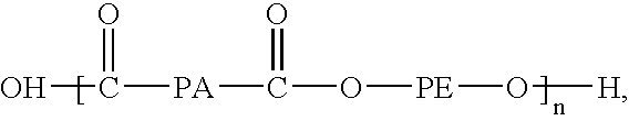
- in which PA represents a polyamide segment, e.g., nylon 12, and PE represents a polyether segment, e.g., poly(tetramethylene glycol) is utilized. Such polymers are commercially available from ATOFINA under the tradename PEBAX®.
- In particular embodiments, the balloon can have three or more layers, e.g., five, seven or more layers, e.g., with all or just some of the layers being modified. In some embodiments only the out layer or outer layers are modified. In other embodiments, only the innermost layer or inner layers are modified. Balloons formed of coextruded polymer layers are described in Wang, U.S. Pat. Nos. 5,366,442 and 5,195,969, Hamlin, U.S. Pat. No. 5,270,086, and Chin, U.S. Pat. No. 6,951,675, the entire contents of each of which is hereby incorporated by reference herein.
- Balloon modification is controlled to produce a desired type of modification at a selected depth. The depth of ion exposure determines the depth of modification. The nature and depth of the modification is also controlled to adjust the overall mechanical properties of the balloon. In particular embodiments, the modification is controlled so that the mechanical properties, such as tensile strength, elongation and modulus of elasticity of the base polymer system are not substantially changed by the presence of the modification. In embodiments, the tensile strength, elongation and modulus of elasticity of the modified polymer is substantially the same as or greater than those respective values of the unmodified polymer. In addition, the modification is controlled so that the desired folding configuration can be achieved.
- In embodiments, the balloon can be used in various vascular or non-vascular applications. Exemplary applications include neuro, arterial, esophageal, or vascular. The balloon can be used in angioplasty procedures and can be used to deliver and expand a stent. Stents and stent delivery is also discussed in U.S. Ser. No. '392, supra, as well as in U.S. application Ser. No. 11/355,368, “Bioerodible Endoprothesis and Methods of Making the Same”, filed on Feb. 16, 2006, the entire contents of which is hereby incorporated by reference.
- All patents, patent applications and publications represented herein are incorporated by reference in their entirety.
- A number of embodiments of the invention have been described. Nevertheless, it will be understood that various modifications may be made without departing from the spirit and scope of the invention. Accordingly, other embodiments are within the scope of the following claims.
Claims (32)
Priority Applications (7)
| Application Number | Priority Date | Filing Date | Title |
|---|---|---|---|
| US11/533,588 US7963942B2 (en) | 2006-09-20 | 2006-09-20 | Medical balloons with modified surfaces |
| CA002660058A CA2660058A1 (en) | 2006-09-20 | 2007-08-29 | Medical balloons with modified surfaces |
| EP07814551A EP2063924B1 (en) | 2006-09-20 | 2007-08-29 | Medical balloons with modified surfaces |
| JP2009529293A JP5209628B2 (en) | 2006-09-20 | 2007-08-29 | Medical device having a modified surface |
| AT07814551T ATE485066T1 (en) | 2006-09-20 | 2007-08-29 | MEDICAL BALLOONS WITH MODIFIED SURFACES |
| PCT/US2007/077151 WO2008036495A2 (en) | 2006-09-20 | 2007-08-29 | Medical balloons with modified surfaces |
| DE602007010008T DE602007010008D1 (en) | 2006-09-20 | 2007-08-29 | MEDICAL BALLOONS WITH MODIFIED SURFACES |
Applications Claiming Priority (1)
| Application Number | Priority Date | Filing Date | Title |
|---|---|---|---|
| US11/533,588 US7963942B2 (en) | 2006-09-20 | 2006-09-20 | Medical balloons with modified surfaces |
Publications (2)
| Publication Number | Publication Date |
|---|---|
| US20080097302A1 true US20080097302A1 (en) | 2008-04-24 |
| US7963942B2 US7963942B2 (en) | 2011-06-21 |
Family
ID=38667129
Family Applications (1)
| Application Number | Title | Priority Date | Filing Date |
|---|---|---|---|
| US11/533,588 Active 2028-06-20 US7963942B2 (en) | 2006-09-20 | 2006-09-20 | Medical balloons with modified surfaces |
Country Status (7)
| Country | Link |
|---|---|
| US (1) | US7963942B2 (en) |
| EP (1) | EP2063924B1 (en) |
| JP (1) | JP5209628B2 (en) |
| AT (1) | ATE485066T1 (en) |
| CA (1) | CA2660058A1 (en) |
| DE (1) | DE602007010008D1 (en) |
| WO (1) | WO2008036495A2 (en) |
Cited By (5)
| Publication number | Priority date | Publication date | Assignee | Title |
|---|---|---|---|---|
| US20070244501A1 (en) * | 2006-04-18 | 2007-10-18 | Horn Daniel J | Medical balloons |
| US20120130407A1 (en) * | 2010-11-22 | 2012-05-24 | Cook Medical Technologies Llc | Scoring balloon and method of making same |
| US20140198379A1 (en) * | 2011-05-24 | 2014-07-17 | National Institute Of Advanced Industrial Science And Technology | Infrared-transmitting film, method for producing infrared-transmitting film, infrared optical component, and infrared device |
| US8827954B2 (en) | 2008-06-05 | 2014-09-09 | Boston Scientific Scimed, Inc. | Deflatable bifurcated device |
| US8936567B2 (en) | 2007-11-14 | 2015-01-20 | Boston Scientific Scimed, Inc. | Balloon bifurcated lumen treatment |
Families Citing this family (18)
| Publication number | Priority date | Publication date | Assignee | Title |
|---|---|---|---|---|
| WO2003041760A2 (en) | 2001-11-09 | 2003-05-22 | Novoste Corporation | Baloon catheter with non-deployable stent |
| US20040111108A1 (en) | 2001-11-09 | 2004-06-10 | Farnan Robert C. | Balloon catheter with non-deployable stent |
| US8080026B2 (en) | 2003-01-21 | 2011-12-20 | Angioscore, Inc. | Apparatus and methods for treating hardened vascular lesions |
| US10076641B2 (en) | 2005-05-11 | 2018-09-18 | The Spectranetics Corporation | Methods and systems for delivering substances into luminal walls |
| US8845581B2 (en) * | 2006-11-14 | 2014-09-30 | Boston Scientific Scimed, Inc. | Medical balloon deflation |
| EP2380604A1 (en) | 2010-04-19 | 2011-10-26 | InnoRa Gmbh | Improved coating formulations for scoring or cutting balloon catheters |
| US8632559B2 (en) | 2010-09-21 | 2014-01-21 | Angioscore, Inc. | Method and system for treating valve stenosis |
| JP6426622B2 (en) | 2013-01-29 | 2018-11-21 | バード シャノン リミテッド | Muscle wall defect prosthesis and placement system |
| JP6134154B2 (en) * | 2013-02-18 | 2017-05-24 | 株式会社カネカ | Balloon for balloon catheter |
| JP5750621B1 (en) * | 2013-07-31 | 2015-07-22 | オリンパス株式会社 | catheter |
| US10117668B2 (en) | 2013-10-08 | 2018-11-06 | The Spectranetics Corporation | Balloon catheter with non-deployable stent having improved stability |
| WO2016089971A1 (en) | 2014-12-02 | 2016-06-09 | Bard Shannon Limited | Muscle wall defect prothesis and deployment system |
| WO2017096350A1 (en) | 2015-12-05 | 2017-06-08 | The Regents Of The University Of Colorado, A Body Corporate | Novel endoscopic devices and methods using same |
| US10449027B2 (en) | 2015-12-28 | 2019-10-22 | C.R. Bard, Inc. | Deployment device for a soft tissue repair prosthesis |
| US10314632B2 (en) | 2016-10-07 | 2019-06-11 | Medtronic Holding Company Sárl | Surgical system and methods of use |
| US11577056B2 (en) | 2018-01-16 | 2023-02-14 | Aspero Medical, Inc. | Medical devices including textured inflatable balloons |
| JP7194459B2 (en) | 2018-01-16 | 2022-12-22 | ザ リージェンツ オブ ザ ユニバーシティ オブ コロラド,ア ボディー コーポレイト | A medical device containing a textured inflatable balloon |
| US11730928B2 (en) | 2018-01-16 | 2023-08-22 | Aspero Medical, Inc. | Split overtube assembly |
Citations (48)
| Publication number | Priority date | Publication date | Assignee | Title |
|---|---|---|---|---|
| US4940421A (en) * | 1988-07-19 | 1990-07-10 | Molex Incorporated | Water-proof electrical connector |
| US4963313A (en) * | 1987-11-30 | 1990-10-16 | Boston Scientific Corporation | Balloon catheter |
| US5047045A (en) * | 1989-04-13 | 1991-09-10 | Scimed Life Systems, Inc. | Multi-section coaxial angioplasty catheter |
| US5195969A (en) * | 1991-04-26 | 1993-03-23 | Boston Scientific Corporation | Co-extruded medical balloons and catheter using such balloons |
| US5270086A (en) * | 1989-09-25 | 1993-12-14 | Schneider (Usa) Inc. | Multilayer extrusion of angioplasty balloons |
| US5348538A (en) * | 1992-09-29 | 1994-09-20 | Scimed Life Systems, Inc. | Shrinking balloon catheter having nonlinear or hybrid compliance curve |
| US5447497A (en) * | 1992-08-06 | 1995-09-05 | Scimed Life Systems, Inc | Balloon catheter having nonlinear compliance curve and method of using |
| US5490839A (en) * | 1993-09-20 | 1996-02-13 | Scimed Life Systems, Inc. | Catheter balloon with retraction coating |
| US5556383A (en) * | 1994-03-02 | 1996-09-17 | Scimed Lifesystems, Inc. | Block copolymer elastomer catheter balloons |
| US5609629A (en) * | 1995-06-07 | 1997-03-11 | Med Institute, Inc. | Coated implantable medical device |
| US5693014A (en) * | 1993-08-23 | 1997-12-02 | Boston Scientific Corporation | Balloon catheter |
| US5746745A (en) * | 1993-08-23 | 1998-05-05 | Boston Scientific Corporation | Balloon catheter |
| US5759172A (en) * | 1995-04-10 | 1998-06-02 | Cordis Corporation | Balloon catheter with lobed balloon and method for manufacturing such a catheter |
| US5766618A (en) * | 1994-04-01 | 1998-06-16 | Massachusetts Institute Of Technology | Polymeric-hydroxyapatite bone composite |
| US5830182A (en) * | 1994-03-02 | 1998-11-03 | Scimed Life Systems, Inc. | Block copolymer elastomer catheter balloons |
| US5945153A (en) * | 1994-07-11 | 1999-08-31 | Southwest Research Institute | Non-irritating antimicrobial coating for medical implants and a process for preparing same |
| US5951941A (en) * | 1994-03-02 | 1999-09-14 | Scimed Life Systems, Inc. | Block copolymer elastomer catheter balloons |
| US6120260A (en) * | 1998-11-17 | 2000-09-19 | Spx Corporation | Soft start valve |
| US6171278B1 (en) * | 1994-03-02 | 2001-01-09 | Scimed Life Systems, Inc. | Block copolymer elastomer catheter balloons |
| US6171287B1 (en) * | 1998-05-29 | 2001-01-09 | Lawrence A. Lynn | Luer receiver and method for fluid transfer |
| US6290721B1 (en) * | 1992-03-31 | 2001-09-18 | Boston Scientific Corporation | Tubular medical endoprostheses |
| US6335029B1 (en) * | 1998-08-28 | 2002-01-01 | Scimed Life Systems, Inc. | Polymeric coatings for controlled delivery of active agents |
| US20020004060A1 (en) * | 1997-07-18 | 2002-01-10 | Bernd Heublein | Metallic implant which is degradable in vivo |
| US6406457B1 (en) * | 1994-03-02 | 2002-06-18 | Scimed Life Systems, Inc. | Block copolymer elastomer catheter balloons |
| US20020082638A1 (en) * | 2000-12-27 | 2002-06-27 | Porter Stephen Christopher | Selectively permeable highly distensible occlusion balloon |
| US6432134B1 (en) * | 1996-07-16 | 2002-08-13 | Anson Medical Limited | Method of producing a surgical implant |
| US6517888B1 (en) * | 2000-11-28 | 2003-02-11 | Scimed Life Systems, Inc. | Method for manufacturing a medical device having a coated portion by laser ablation |
| US6531182B2 (en) * | 1999-05-03 | 2003-03-11 | Guardian Industries Corp. | Method of making a coated article including DLC and FAS |
| US6562445B2 (en) * | 2000-03-23 | 2003-05-13 | Kabushiki Kaisha Kobe Seiko Sho (Kobe Steel, Ltd.) | Diamond-like carbon hard multilayer film and component excellent in wear resistance and sliding performance |
| US20030104028A1 (en) * | 2001-11-29 | 2003-06-05 | Hossainy Syed F.A. | Rate limiting barriers for implantable devices and methods for fabrication thereof |
| US20030144683A1 (en) * | 2001-12-13 | 2003-07-31 | Avantec Vascular Corporation | Inflatable members having concentrated force regions |
| US20030163148A1 (en) * | 2002-02-27 | 2003-08-28 | Lixiao Wang | Medical device |
| US20030221307A1 (en) * | 2002-02-20 | 2003-12-04 | University Of Hannover | Process for producing bioresorbable implants |
| US6720402B2 (en) * | 1998-02-23 | 2004-04-13 | Mnemoscience Gmbh | Shape memory polymers |
| US6726712B1 (en) * | 1999-05-14 | 2004-04-27 | Boston Scientific Scimed | Prosthesis deployment device with translucent distal end |
| US6753071B1 (en) * | 2001-09-27 | 2004-06-22 | Advanced Cardiovascular Systems, Inc. | Rate-reducing membrane for release of an agent |
| US20040225318A1 (en) * | 2003-05-05 | 2004-11-11 | Tracee Eidenschink | Balloon catheter and method of making same |
| US20050010275A1 (en) * | 2002-10-11 | 2005-01-13 | Sahatjian Ronald A. | Implantable medical devices |
| US20050015046A1 (en) * | 2003-07-18 | 2005-01-20 | Scimed Life Systems, Inc. | Medical devices and processes for preparing same |
| US6908506B2 (en) * | 2000-07-03 | 2005-06-21 | Kyphon Inc. | Magnesium ammonium phosphate cement composition |
| US20050177130A1 (en) * | 2004-02-10 | 2005-08-11 | Angioscore, Inc. | Balloon catheter with spiral folds |
| US6951675B2 (en) * | 2003-01-27 | 2005-10-04 | Scimed Life Systems, Inc. | Multilayer balloon catheter |
| US6953594B2 (en) * | 1996-10-10 | 2005-10-11 | Etex Corporation | Method of preparing a poorly crystalline calcium phosphate and methods of its use |
| US20060079863A1 (en) * | 2004-10-08 | 2006-04-13 | Scimed Life Systems, Inc. | Medical devices coated with diamond-like carbon |
| US20060182873A1 (en) * | 2005-02-17 | 2006-08-17 | Klisch Leo M | Medical devices |
| US20070050007A1 (en) * | 2005-08-18 | 2007-03-01 | Boston Scientific Scimed, Inc. | Surface modification of ePTFE and implants using the same |
| US20070191923A1 (en) * | 2006-02-16 | 2007-08-16 | Jan Weber | Medical balloons and methods of making the same |
| US20070191931A1 (en) * | 2006-02-16 | 2007-08-16 | Jan Weber | Bioerodible endoprostheses and methods of making the same |
Family Cites Families (15)
| Publication number | Priority date | Publication date | Assignee | Title |
|---|---|---|---|---|
| JPS59192366A (en) | 1983-04-15 | 1984-10-31 | 住友電気工業株式会社 | Artificial heart valve |
| US4490421A (en) | 1983-07-05 | 1984-12-25 | E. I. Du Pont De Nemours And Company | Balloon and manufacture thereof |
| JPS60135062A (en) | 1983-12-23 | 1985-07-18 | 住友電気工業株式会社 | Artificial blood vessel |
| EP0302717A1 (en) | 1987-08-04 | 1989-02-08 | Ion Tech Limited | Body implant |
| AU671982B2 (en) | 1992-04-21 | 1996-09-19 | Cook Urological Inc. | Surface-treated medical device |
| US5503631A (en) | 1992-10-09 | 1996-04-02 | Terumo Kabushiki Kaisha | Lubricious catheter balloon for vasodilation |
| GB9405029D0 (en) | 1994-03-15 | 1994-04-27 | Franks Joseph Dr | Improved catheters and other tubular inserts |
| US5458572A (en) * | 1994-07-01 | 1995-10-17 | Boston Scientific Corp. | Catheter with balloon folding into predetermined configurations and method of manufacture |
| GB9709071D0 (en) | 1997-05-02 | 1997-06-25 | Howmedica | A process for improving start up and steady rate friction of soft/compliant polyurethanes |
| US6761736B1 (en) | 1999-11-10 | 2004-07-13 | St. Jude Medical, Inc. | Medical article with a diamond-like carbon coated polymer |
| US7077859B2 (en) | 2000-12-22 | 2006-07-18 | Avantec Vascular Corporation | Apparatus and methods for variably controlled substance delivery from implanted prostheses |
| US7335184B2 (en) | 2002-07-02 | 2008-02-26 | Sentient Engineering And Technology | Balloon catheter and treatment apparatus |
| US7335185B2 (en) * | 2003-07-18 | 2008-02-26 | Boston Scientific Scimed, Inc. | Protective coatings for medical devices |
| JP2005040277A (en) * | 2003-07-28 | 2005-02-17 | Aisin Seiki Co Ltd | Balloon catheter |
| US20070244501A1 (en) | 2006-04-18 | 2007-10-18 | Horn Daniel J | Medical balloons |
-
2006
- 2006-09-20 US US11/533,588 patent/US7963942B2/en active Active
-
2007
- 2007-08-29 AT AT07814551T patent/ATE485066T1/en not_active IP Right Cessation
- 2007-08-29 JP JP2009529293A patent/JP5209628B2/en not_active Expired - Fee Related
- 2007-08-29 WO PCT/US2007/077151 patent/WO2008036495A2/en active Application Filing
- 2007-08-29 CA CA002660058A patent/CA2660058A1/en not_active Abandoned
- 2007-08-29 EP EP07814551A patent/EP2063924B1/en not_active Not-in-force
- 2007-08-29 DE DE602007010008T patent/DE602007010008D1/en active Active
Patent Citations (50)
| Publication number | Priority date | Publication date | Assignee | Title |
|---|---|---|---|---|
| US4963313A (en) * | 1987-11-30 | 1990-10-16 | Boston Scientific Corporation | Balloon catheter |
| US4940421A (en) * | 1988-07-19 | 1990-07-10 | Molex Incorporated | Water-proof electrical connector |
| US5047045A (en) * | 1989-04-13 | 1991-09-10 | Scimed Life Systems, Inc. | Multi-section coaxial angioplasty catheter |
| US5270086A (en) * | 1989-09-25 | 1993-12-14 | Schneider (Usa) Inc. | Multilayer extrusion of angioplasty balloons |
| US5195969A (en) * | 1991-04-26 | 1993-03-23 | Boston Scientific Corporation | Co-extruded medical balloons and catheter using such balloons |
| US5366442A (en) * | 1991-04-26 | 1994-11-22 | Boston Scientific Corp. | Sleeve for attaching a medical balloon to a catheter |
| US6290721B1 (en) * | 1992-03-31 | 2001-09-18 | Boston Scientific Corporation | Tubular medical endoprostheses |
| US5447497A (en) * | 1992-08-06 | 1995-09-05 | Scimed Life Systems, Inc | Balloon catheter having nonlinear compliance curve and method of using |
| US5348538A (en) * | 1992-09-29 | 1994-09-20 | Scimed Life Systems, Inc. | Shrinking balloon catheter having nonlinear or hybrid compliance curve |
| US5403340A (en) * | 1992-09-29 | 1995-04-04 | Scimed Lifesystems Inc. | Shrinking balloon catheter having nonlinear compliance curve |
| US5693014A (en) * | 1993-08-23 | 1997-12-02 | Boston Scientific Corporation | Balloon catheter |
| US5746745A (en) * | 1993-08-23 | 1998-05-05 | Boston Scientific Corporation | Balloon catheter |
| US5490839A (en) * | 1993-09-20 | 1996-02-13 | Scimed Life Systems, Inc. | Catheter balloon with retraction coating |
| US6171278B1 (en) * | 1994-03-02 | 2001-01-09 | Scimed Life Systems, Inc. | Block copolymer elastomer catheter balloons |
| US5556383A (en) * | 1994-03-02 | 1996-09-17 | Scimed Lifesystems, Inc. | Block copolymer elastomer catheter balloons |
| US6406457B1 (en) * | 1994-03-02 | 2002-06-18 | Scimed Life Systems, Inc. | Block copolymer elastomer catheter balloons |
| US5830182A (en) * | 1994-03-02 | 1998-11-03 | Scimed Life Systems, Inc. | Block copolymer elastomer catheter balloons |
| US5951941A (en) * | 1994-03-02 | 1999-09-14 | Scimed Life Systems, Inc. | Block copolymer elastomer catheter balloons |
| US5766618A (en) * | 1994-04-01 | 1998-06-16 | Massachusetts Institute Of Technology | Polymeric-hydroxyapatite bone composite |
| US5945153A (en) * | 1994-07-11 | 1999-08-31 | Southwest Research Institute | Non-irritating antimicrobial coating for medical implants and a process for preparing same |
| US5759172A (en) * | 1995-04-10 | 1998-06-02 | Cordis Corporation | Balloon catheter with lobed balloon and method for manufacturing such a catheter |
| US5609629A (en) * | 1995-06-07 | 1997-03-11 | Med Institute, Inc. | Coated implantable medical device |
| US6432134B1 (en) * | 1996-07-16 | 2002-08-13 | Anson Medical Limited | Method of producing a surgical implant |
| US6953594B2 (en) * | 1996-10-10 | 2005-10-11 | Etex Corporation | Method of preparing a poorly crystalline calcium phosphate and methods of its use |
| US20020004060A1 (en) * | 1997-07-18 | 2002-01-10 | Bernd Heublein | Metallic implant which is degradable in vivo |
| US6720402B2 (en) * | 1998-02-23 | 2004-04-13 | Mnemoscience Gmbh | Shape memory polymers |
| US6171287B1 (en) * | 1998-05-29 | 2001-01-09 | Lawrence A. Lynn | Luer receiver and method for fluid transfer |
| US6335029B1 (en) * | 1998-08-28 | 2002-01-01 | Scimed Life Systems, Inc. | Polymeric coatings for controlled delivery of active agents |
| US6120260A (en) * | 1998-11-17 | 2000-09-19 | Spx Corporation | Soft start valve |
| US6531182B2 (en) * | 1999-05-03 | 2003-03-11 | Guardian Industries Corp. | Method of making a coated article including DLC and FAS |
| US6726712B1 (en) * | 1999-05-14 | 2004-04-27 | Boston Scientific Scimed | Prosthesis deployment device with translucent distal end |
| US6562445B2 (en) * | 2000-03-23 | 2003-05-13 | Kabushiki Kaisha Kobe Seiko Sho (Kobe Steel, Ltd.) | Diamond-like carbon hard multilayer film and component excellent in wear resistance and sliding performance |
| US6908506B2 (en) * | 2000-07-03 | 2005-06-21 | Kyphon Inc. | Magnesium ammonium phosphate cement composition |
| US6517888B1 (en) * | 2000-11-28 | 2003-02-11 | Scimed Life Systems, Inc. | Method for manufacturing a medical device having a coated portion by laser ablation |
| US20020082638A1 (en) * | 2000-12-27 | 2002-06-27 | Porter Stephen Christopher | Selectively permeable highly distensible occlusion balloon |
| US6753071B1 (en) * | 2001-09-27 | 2004-06-22 | Advanced Cardiovascular Systems, Inc. | Rate-reducing membrane for release of an agent |
| US20030104028A1 (en) * | 2001-11-29 | 2003-06-05 | Hossainy Syed F.A. | Rate limiting barriers for implantable devices and methods for fabrication thereof |
| US20030144683A1 (en) * | 2001-12-13 | 2003-07-31 | Avantec Vascular Corporation | Inflatable members having concentrated force regions |
| US20030221307A1 (en) * | 2002-02-20 | 2003-12-04 | University Of Hannover | Process for producing bioresorbable implants |
| US20030163148A1 (en) * | 2002-02-27 | 2003-08-28 | Lixiao Wang | Medical device |
| US20050010275A1 (en) * | 2002-10-11 | 2005-01-13 | Sahatjian Ronald A. | Implantable medical devices |
| US6951675B2 (en) * | 2003-01-27 | 2005-10-04 | Scimed Life Systems, Inc. | Multilayer balloon catheter |
| US20040225318A1 (en) * | 2003-05-05 | 2004-11-11 | Tracee Eidenschink | Balloon catheter and method of making same |
| US20050015046A1 (en) * | 2003-07-18 | 2005-01-20 | Scimed Life Systems, Inc. | Medical devices and processes for preparing same |
| US20050177130A1 (en) * | 2004-02-10 | 2005-08-11 | Angioscore, Inc. | Balloon catheter with spiral folds |
| US20060079863A1 (en) * | 2004-10-08 | 2006-04-13 | Scimed Life Systems, Inc. | Medical devices coated with diamond-like carbon |
| US20060182873A1 (en) * | 2005-02-17 | 2006-08-17 | Klisch Leo M | Medical devices |
| US20070050007A1 (en) * | 2005-08-18 | 2007-03-01 | Boston Scientific Scimed, Inc. | Surface modification of ePTFE and implants using the same |
| US20070191923A1 (en) * | 2006-02-16 | 2007-08-16 | Jan Weber | Medical balloons and methods of making the same |
| US20070191931A1 (en) * | 2006-02-16 | 2007-08-16 | Jan Weber | Bioerodible endoprostheses and methods of making the same |
Cited By (7)
| Publication number | Priority date | Publication date | Assignee | Title |
|---|---|---|---|---|
| US20070244501A1 (en) * | 2006-04-18 | 2007-10-18 | Horn Daniel J | Medical balloons |
| US8936567B2 (en) | 2007-11-14 | 2015-01-20 | Boston Scientific Scimed, Inc. | Balloon bifurcated lumen treatment |
| US8827954B2 (en) | 2008-06-05 | 2014-09-09 | Boston Scientific Scimed, Inc. | Deflatable bifurcated device |
| US20120130407A1 (en) * | 2010-11-22 | 2012-05-24 | Cook Medical Technologies Llc | Scoring balloon and method of making same |
| WO2012071095A1 (en) * | 2010-11-22 | 2012-05-31 | Cook Medical Technologies Llc | Scoring balloon and method of making same |
| US20140198379A1 (en) * | 2011-05-24 | 2014-07-17 | National Institute Of Advanced Industrial Science And Technology | Infrared-transmitting film, method for producing infrared-transmitting film, infrared optical component, and infrared device |
| US9575216B2 (en) * | 2011-05-24 | 2017-02-21 | National Institute Of Advanced Industrial Science And Technology | Infrared-transmitting film, method for producing infrared-transmitting film, infrared optical component, and infrared device |
Also Published As
| Publication number | Publication date |
|---|---|
| JP2010504161A (en) | 2010-02-12 |
| WO2008036495A2 (en) | 2008-03-27 |
| ATE485066T1 (en) | 2010-11-15 |
| US7963942B2 (en) | 2011-06-21 |
| JP5209628B2 (en) | 2013-06-12 |
| WO2008036495A3 (en) | 2009-02-05 |
| EP2063924A2 (en) | 2009-06-03 |
| EP2063924B1 (en) | 2010-10-20 |
| DE602007010008D1 (en) | 2010-12-02 |
| CA2660058A1 (en) | 2008-03-27 |
Similar Documents
| Publication | Publication Date | Title |
|---|---|---|
| US7963942B2 (en) | Medical balloons with modified surfaces | |
| EP3220994B1 (en) | Balloon catheter system | |
| US9526814B2 (en) | Medical balloons and methods of making the same | |
| US5490839A (en) | Catheter balloon with retraction coating | |
| US5496276A (en) | Catheter balloon with retraction coating | |
| US5738901A (en) | Catheter balloon with retraction coating | |
| US7998184B2 (en) | Crimpable balloon stent protector | |
| JP4865188B2 (en) | Balloon catheter with striped flexible tip | |
| US8845581B2 (en) | Medical balloon deflation | |
| WO1998003218A1 (en) | High compliance, high strength catheter balloons useful for treatment of gastrointestinal lesions | |
| WO1998003218A9 (en) | High compliance, high strength catheter balloons useful for treatment of gastrointestinal lesions | |
| US20070009692A1 (en) | High compliance, high strength catheter balloons useful for treatment of gastrointestinal lesions | |
| CA2741685A1 (en) | Rupture-resistant compliant radiopaque catheter balloon and methods for use of same in an intravascular surgical procedure | |
| US20220054804A1 (en) | Medical balloon | |
| US20090254113A1 (en) | Dilatation balloon with ridges and methods | |
| WO2018200661A1 (en) | Medical balloon | |
| US20180161040A1 (en) | Medical balloon | |
| JP2006262932A (en) | Balloon catheter |
Legal Events
| Date | Code | Title | Description |
|---|---|---|---|
| AS | Assignment |
Owner name: BOSTON SCIENTIFIC SCIMED, INC., MINNESOTA Free format text: ASSIGNMENT OF ASSIGNORS INTEREST;ASSIGNOR:CHEN, JOHN JIANHUA;REEL/FRAME:018439/0272 Effective date: 20060918 |
|
| STCF | Information on status: patent grant |
Free format text: PATENTED CASE |
|
| FPAY | Fee payment |
Year of fee payment: 4 |
|
| MAFP | Maintenance fee payment |
Free format text: PAYMENT OF MAINTENANCE FEE, 8TH YEAR, LARGE ENTITY (ORIGINAL EVENT CODE: M1552); ENTITY STATUS OF PATENT OWNER: LARGE ENTITY Year of fee payment: 8 |
|
| MAFP | Maintenance fee payment |
Free format text: PAYMENT OF MAINTENANCE FEE, 12TH YEAR, LARGE ENTITY (ORIGINAL EVENT CODE: M1553); ENTITY STATUS OF PATENT OWNER: LARGE ENTITY Year of fee payment: 12 |