US20080098143A1 - Apparatus Using A Time Division Multiple Access Bus For Providing Multiple Levels Of Security In A Communications System - Google Patents
Apparatus Using A Time Division Multiple Access Bus For Providing Multiple Levels Of Security In A Communications System Download PDFInfo
- Publication number
- US20080098143A1 US20080098143A1 US11/659,670 US65967006A US2008098143A1 US 20080098143 A1 US20080098143 A1 US 20080098143A1 US 65967006 A US65967006 A US 65967006A US 2008098143 A1 US2008098143 A1 US 2008098143A1
- Authority
- US
- United States
- Prior art keywords
- bus
- time slot
- clock
- switch units
- ports
- Prior art date
- Legal status (The legal status is an assumption and is not a legal conclusion. Google has not performed a legal analysis and makes no representation as to the accuracy of the status listed.)
- Granted
Links
Images


Classifications
-
- H—ELECTRICITY
- H04—ELECTRIC COMMUNICATION TECHNIQUE
- H04L—TRANSMISSION OF DIGITAL INFORMATION, e.g. TELEGRAPHIC COMMUNICATION
- H04L63/00—Network architectures or network communication protocols for network security
- H04L63/10—Network architectures or network communication protocols for network security for controlling access to devices or network resources
- H04L63/105—Multiple levels of security
-
- G—PHYSICS
- G06—COMPUTING; CALCULATING OR COUNTING
- G06F—ELECTRIC DIGITAL DATA PROCESSING
- G06F21/00—Security arrangements for protecting computers, components thereof, programs or data against unauthorised activity
- G06F21/70—Protecting specific internal or peripheral components, in which the protection of a component leads to protection of the entire computer
- G06F21/82—Protecting input, output or interconnection devices
- G06F21/85—Protecting input, output or interconnection devices interconnection devices, e.g. bus-connected or in-line devices
Definitions
- the present invention relates generally to a security system for use in a communications system and, more particularly, to a security system that provides multiple levels of security using a time division multiple access bus.
- DOD 5200.28-STD entitled “Department Of Defense Trusted Computer System Evaluation Criteria,” dated December 1985.
- the criteria are characterized by four divisions, namely, “A, B, C and D”.
- Division A is the highest protection, and is known as “Verified Protection.”
- the next level is “Division B: Mandatory Protection”; followed by “Division C: Discretionary Protection”; followed by the lowest level “Division D: Minimal Protection.”
- DOD5200.28-STD also provides the mandatory access control requirements for these levels of security.
- MSLS Multiple Single Levels of Security
- the inventors of the prior application recognized that there was a need in the art for a MSLS system capable of meeting all of the security requirements of such systems, in addition to permitting the distribution of intelligence or secure information or material in a manner minimizing security certification efforts, while providing networking functionality between channels operating with the same security label. They further recognized that there was a need for such MSLS records and apparatus not only for JTRS systems, but also for use in any applicable communications system requiring MSLS.
- the prior application thus discloses a system wherein a physical switch provides multiple single levels of security. However, in the system disclosed in the prior application, all switching was centralized and required that separate cabling be run from the central control to all the individual ports and channels of the communications system.
- the inventors of the present system have recognized that it would be more efficient and economical if only a single cable was used to connect all the ports and channels of the communications system. Also, the prior invention required physical separation of signals, limiting the number of possible connections to the available routing resources. It would therefore be desirable to use bandwidth resources instead, allowing for a larger number of interconnects in the same resource space.
- a system providing communication at multiple levels of security for associated apparatus.
- the associated apparatus includes a plurality of ports and a plurality of channels, wherein each of the ports and channels is assigned transmit and receive time slots and each of the ports is only permitted to communicate with a channel having matching time slots.
- the system comprises a data bus for connection to all of the ports and channels, a control bus (which could share the same physical resources as the data bus) for connection to all of the ports and channels, a plurality of switch units each associated with a respective one of the ports and channels and each coupled between the bus and the respective one of the ports and channels, a clock and sync circuit coupled to the busses, and a high assurance control source connected to the control bus.
- the clock and sync circuit is operative to provide configuration signals on the data bus to define a plurality of time slots.
- the high assurance source is operative to assign a transmit time slot and a receive time slot to a selected port switch unit, and assign a transmit time slot and a receive time slot to a selected channel switch unit.
- the high assurance source ensures that a transmit time slot for a selected port switch unit is the same as a receive time slot for a selected channel switch unit and a receive time slot for the selected port switch unit is the same as a transmit time slot for the selected channel switch unit only when the port associated with the selected port switch unit and the channel associated with the selected channel switch unit have a matching designated security level.
- the present invention uses a “virtual” switch (i.e., time division) which is dedicated to only a single level of security. Multiple switches provide multiple levels of security.
- the inventive system architecture can be either distributed or central, and in each case can either have separate control and data buses or can use a single time division bus for both control and data transmission.
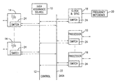
- FIG. 1 is a block diagram depicting a first illustrative embodiment of a system according to the present invention having a distributed architecture with separate control and data buses;
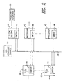
- FIG. 2 is a block diagram depicting a second illustrative embodiment of a system according to the present invention having a distributed architecture with a single bus for both control and data;
- FIG. 3 is a block diagram depicting an illustrative embodiment of a system according to the present invention having a centralized architecture
- FIG. 4 is a block diagram of an illustrative embodiment of a switch unit according to the present invention which may be utilized in the system shown in FIG. 1 ;
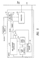
- FIG. 5 is a block diagram of an illustrative embodiment of a switch unit according to the present invention which may be utilized in the system shown in FIG. 2 ;
- FIG. 6 is a block diagram of an illustrative embodiment of a switch unit according to the present invention which may be utilized in the system shown in FIG. 3 .
- FIG. 1 illustrates the present invention as applied to a system having a distributed architecture with separate serial control and data buses.
- the use of a serial bus is advantageous over the use of separate cabling to a plurality of peripheral devices because only a single cable has to be run to connect to all of the peripheral devices.
- System control is effected by the high assurance source 10 , which ensures that only those peripheral devices having the same designated security level can communicate with each other.
- the high assurance source 10 is connected to the control bus 12 , which is a serial bus extending to all the peripheral devices of the system.
- the peripheral devices are the ports 14 , shown on the left side of the control bus 12 and labeled “I/O”, and the channels 16 , shown on the right side of the control bus 12 and labeled “PROCESSOR”.
- a clock and sync circuit 18 connected to the control bus 12 and receiving input signals from a frequency reference circuit 20 .
- the system also includes a separate serial time division multiple access (TDMA) data bus 22 extending to all the ports 14 and the channels 16 , as well as to the clock and sync circuit 18 .
- the clock and sync circuit 18 is operative to provide configuration signals on the data bus 22 to define a plurality of time slots.
- TDMA serial time division multiple access
- Each of the peripheral devices (each also hereinafter referred to as an “entity”) 14 , 16 , 18 has an internal switch unit 24 which provides the direct, and only, connection between each associated entity and the buses 12 and 22 .
- each switch unit 24 includes a controller 26 for receiving time slot assignments (both receive and transmit) over the control bus 12 from the high assurance source 10 , and a memory 28 for storing the time slot assignments.
- the switch unit 24 also includes a transceiver 30 coupled to the data bus 22 and a first-in-first-out (FIFO) register and interleaver 32 coupled between the transceiver 30 and the associated entity 14 , 16 , 18 .
- the phase locked loop circuit 34 and the clock data recovery circuit 36 retrieve timing signals over the data bus 22 from the clock and sync circuit 18 .
- the high assurance source 10 checks to see if that port and channel have the same designated security level. If not, a connection is not set up. If the security levels match, the high assurance source 10 assigns, over the control bus 12 , receive and transmit time slots to the port and channel switch units of those particular port and channel.
- the receive time slot for the port switch unit is the transmit time slot for the channel switch unit
- the transmit time slot for the port switch unit is the receive time slot for the channel switch unit.
- Each entity is only connected to the data bus 22 during its allotted time slots. For networking, one transmitter and multiple receivers are allowable, provided that the security levels match.
- FIG. 2 illustrates the present invention as applied to a system having a distributed architecture, as in FIG. 1 , but with only a single serial TDMA bus 38 carrying both data and control.
- control is effected by the high assurance source 10 .
- the ports 40 and the channels 42 are connected to the bus 38 , each through its own internal switch unit 44 .
- the clock and sync circuit 46 which is connected to the frequency reference circuit 20 , is also connected to the bus 38 through its internal switch unit 44 .
- FIG. 5 An exemplary switch unit 44 is illustrated in FIG. 5 , from which it can be seen that the switch unit 44 is substantially the same as the switch unit 24 illustrated in FIG. 4 , with the only substantial difference being that the switch unit 44 is connected to only the single bus 38 , rather than to the two separate data and control buses 22 and 12 .
- the system of FIG. 2 operates substantially the same as the system of FIG. 1 , except that control, clock and data signals all travel over the single TDMA bus 38 .
- FIG. 3 illustrates the present invention as applied to a system having a centralized architecture.
- the circuitry 50 within the broken lines, and to which the high assurance source 10 is connected may be implemented by an application specific integrated circuit (ASIC).
- ASIC application specific integrated circuit
- the ASIC 50 is connected through its internal switch units 52 to the ports 54 and the channels 56 .
- the internal clock and sync circuit 58 is connected to the external frequency reference 20 .
- the high assurance source 10 is connected to the control bus 60 within the ASIC 50 , and all the switch units 52 are connected to the control bus 60 and the data bus 62 within the ASIC 50 .
- the buses 60 and 62 are parallel TDMA buses, which greatly increases throughput as compared with the serial buses of the systems shown in FIGS. 1 and 2 .
- FIG. 6 An exemplary switch unit 52 is illustrated in FIG. 6 , from which it can be seen that the switch unit 52 is similar to the switch units 24 and 44 . One difference is that the transceiver 64 has parallel connections to the data bus 62 . Further, a first-in-first-out register and serial-to-parallel converter 66 is coupled between the transceiver 64 and the associated entity 54 , 56 .
- FIG. 3 In operation, the system of FIG. 3 operates substantially the same as the systems of FIGS. 1 and 2 .
Landscapes
- Engineering & Computer Science (AREA)
- Computer Security & Cryptography (AREA)
- Computer Hardware Design (AREA)
- Theoretical Computer Science (AREA)
- General Engineering & Computer Science (AREA)
- Signal Processing (AREA)
- Computer Networks & Wireless Communication (AREA)
- Software Systems (AREA)
- Physics & Mathematics (AREA)
- General Physics & Mathematics (AREA)
- Computing Systems (AREA)
- Small-Scale Networks (AREA)
- Time-Division Multiplex Systems (AREA)
- Bus Control (AREA)
Abstract
Description
- The present application claims the benefit of Provisional Application Ser. No. 60/684,693 filed May 26, 2005, and entitled “Bus Architecture for High Assurance Data Interface Switch.” The contents of that application are hereby incorporated by reference.
- The present invention relates generally to a security system for use in a communications system and, more particularly, to a security system that provides multiple levels of security using a time division multiple access bus.
- Present communications systems, typically bidirectional communications systems, whether for military, industrial or commercial use, or for use between private individuals, typically require separate physical systems for each security level supported. The requirements depend upon the types of information being communicated, and upon the parties involved in the communication.
- Different levels of security are defined in DOD 5200.28-STD, entitled “Department Of Defense Trusted Computer System Evaluation Criteria,” dated December 1985. In broad terms, the criteria are characterized by four divisions, namely, “A, B, C and D”. Division A is the highest protection, and is known as “Verified Protection.” The next level is “Division B: Mandatory Protection”; followed by “Division C: Discretionary Protection”; followed by the lowest level “Division D: Minimal Protection.” DOD5200.28-STD also provides the mandatory access control requirements for these levels of security.
- Particularly in the military field, including the armed forces and DOD, and governmental agencies such as NASA, and many others, hierarchical mandatory access control is required. Similarly, hospitals and commercial companies, for example, may require non-hierarchical mandatory access control to be maintained for their information or material.
- Prior U.S. patent application Ser. No. 10/837,790, filed May 3, 2004, entitled “METHOD AND APPARATUS PROVIDING MULTIPLE SINGLE LEVELS OF SECURITY FOR DISTRIBUTED PROCESSING IN COMMUNICATIONS SYSTEMS”, and assigned to the assignee of the present invention, describes the use of Multiple Single Levels of Security (MSLS) in the Joint Tactical Radio System, known under the acronym JTRS. The known MSLS systems require involved security certifications, and typically have inadequate networking capability. Accordingly, the inventors of the prior application recognized that there was a need in the art for a MSLS system capable of meeting all of the security requirements of such systems, in addition to permitting the distribution of intelligence or secure information or material in a manner minimizing security certification efforts, while providing networking functionality between channels operating with the same security label. They further recognized that there was a need for such MSLS records and apparatus not only for JTRS systems, but also for use in any applicable communications system requiring MSLS. The prior application thus discloses a system wherein a physical switch provides multiple single levels of security. However, in the system disclosed in the prior application, all switching was centralized and required that separate cabling be run from the central control to all the individual ports and channels of the communications system. The inventors of the present system have recognized that it would be more efficient and economical if only a single cable was used to connect all the ports and channels of the communications system. Also, the prior invention required physical separation of signals, limiting the number of possible connections to the available routing resources. It would therefore be desirable to use bandwidth resources instead, allowing for a larger number of interconnects in the same resource space.
- According to the present invention, there is provided a system providing communication at multiple levels of security for associated apparatus. The associated apparatus includes a plurality of ports and a plurality of channels, wherein each of the ports and channels is assigned transmit and receive time slots and each of the ports is only permitted to communicate with a channel having matching time slots. The system comprises a data bus for connection to all of the ports and channels, a control bus (which could share the same physical resources as the data bus) for connection to all of the ports and channels, a plurality of switch units each associated with a respective one of the ports and channels and each coupled between the bus and the respective one of the ports and channels, a clock and sync circuit coupled to the busses, and a high assurance control source connected to the control bus. The clock and sync circuit is operative to provide configuration signals on the data bus to define a plurality of time slots. The high assurance source is operative to assign a transmit time slot and a receive time slot to a selected port switch unit, and assign a transmit time slot and a receive time slot to a selected channel switch unit. The high assurance source ensures that a transmit time slot for a selected port switch unit is the same as a receive time slot for a selected channel switch unit and a receive time slot for the selected port switch unit is the same as a transmit time slot for the selected channel switch unit only when the port associated with the selected port switch unit and the channel associated with the selected channel switch unit have a matching designated security level.
- Thus, the present invention uses a “virtual” switch (i.e., time division) which is dedicated to only a single level of security. Multiple switches provide multiple levels of security.
- The inventive system architecture can be either distributed or central, and in each case can either have separate control and data buses or can use a single time division bus for both control and data transmission.
- The foregoing will be more readily apparent from reading the following description in conjunction with the drawings in which like elements in different figures are identified by the same reference numeral and wherein:
-
FIG. 1 is a block diagram depicting a first illustrative embodiment of a system according to the present invention having a distributed architecture with separate control and data buses; -
FIG. 2 is a block diagram depicting a second illustrative embodiment of a system according to the present invention having a distributed architecture with a single bus for both control and data; -
FIG. 3 is a block diagram depicting an illustrative embodiment of a system according to the present invention having a centralized architecture; -
FIG. 4 is a block diagram of an illustrative embodiment of a switch unit according to the present invention which may be utilized in the system shown inFIG. 1 ; -
FIG. 5 is a block diagram of an illustrative embodiment of a switch unit according to the present invention which may be utilized in the system shown inFIG. 2 ; and -
FIG. 6 is a block diagram of an illustrative embodiment of a switch unit according to the present invention which may be utilized in the system shown inFIG. 3 . -
FIG. 1 illustrates the present invention as applied to a system having a distributed architecture with separate serial control and data buses. Under certain circumstances, the use of a serial bus is advantageous over the use of separate cabling to a plurality of peripheral devices because only a single cable has to be run to connect to all of the peripheral devices. System control is effected by thehigh assurance source 10, which ensures that only those peripheral devices having the same designated security level can communicate with each other. Thus, thehigh assurance source 10 is connected to thecontrol bus 12, which is a serial bus extending to all the peripheral devices of the system. InFIG. 1 , the peripheral devices are theports 14, shown on the left side of thecontrol bus 12 and labeled “I/O”, and thechannels 16, shown on the right side of thecontrol bus 12 and labeled “PROCESSOR”. In addition, there is a clock andsync circuit 18 connected to thecontrol bus 12 and receiving input signals from afrequency reference circuit 20. The system also includes a separate serial time division multiple access (TDMA)data bus 22 extending to all theports 14 and thechannels 16, as well as to the clock andsync circuit 18. The clock andsync circuit 18 is operative to provide configuration signals on thedata bus 22 to define a plurality of time slots. - Each of the peripheral devices (each also hereinafter referred to as an “entity”) 14, 16, 18 has an
internal switch unit 24 which provides the direct, and only, connection between each associated entity and thebuses FIG. 4 , eachswitch unit 24 includes acontroller 26 for receiving time slot assignments (both receive and transmit) over thecontrol bus 12 from thehigh assurance source 10, and amemory 28 for storing the time slot assignments. Theswitch unit 24 also includes atransceiver 30 coupled to thedata bus 22 and a first-in-first-out (FIFO) register andinterleaver 32 coupled between thetransceiver 30 and the associatedentity loop circuit 34 and the clockdata recovery circuit 36 retrieve timing signals over thedata bus 22 from the clock andsync circuit 18. - In operation, when a
particular port 14 desires to communicate with aparticular channel 16, thehigh assurance source 10 checks to see if that port and channel have the same designated security level. If not, a connection is not set up. If the security levels match, thehigh assurance source 10 assigns, over thecontrol bus 12, receive and transmit time slots to the port and channel switch units of those particular port and channel. Thus, the receive time slot for the port switch unit is the transmit time slot for the channel switch unit, and the transmit time slot for the port switch unit is the receive time slot for the channel switch unit. Each entity is only connected to thedata bus 22 during its allotted time slots. For networking, one transmitter and multiple receivers are allowable, provided that the security levels match. -
FIG. 2 illustrates the present invention as applied to a system having a distributed architecture, as inFIG. 1 , but with only a singleserial TDMA bus 38 carrying both data and control. As in the system ofFIG. 1 , control is effected by thehigh assurance source 10. Theports 40 and thechannels 42 are connected to thebus 38, each through its owninternal switch unit 44. In addition, the clock andsync circuit 46, which is connected to thefrequency reference circuit 20, is also connected to thebus 38 through itsinternal switch unit 44. - An
exemplary switch unit 44 is illustrated inFIG. 5 , from which it can be seen that theswitch unit 44 is substantially the same as theswitch unit 24 illustrated inFIG. 4 , with the only substantial difference being that theswitch unit 44 is connected to only thesingle bus 38, rather than to the two separate data andcontrol buses - In operation, the system of
FIG. 2 operates substantially the same as the system ofFIG. 1 , except that control, clock and data signals all travel over thesingle TDMA bus 38. -
FIG. 3 illustrates the present invention as applied to a system having a centralized architecture. In the system ofFIG. 3 , thecircuitry 50 within the broken lines, and to which thehigh assurance source 10 is connected, may be implemented by an application specific integrated circuit (ASIC). Thus, theASIC 50 is connected through itsinternal switch units 52 to theports 54 and thechannels 56. In addition, the internal clock andsync circuit 58 is connected to theexternal frequency reference 20. Thehigh assurance source 10 is connected to thecontrol bus 60 within theASIC 50, and all theswitch units 52 are connected to thecontrol bus 60 and thedata bus 62 within theASIC 50. Preferably, thebuses FIGS. 1 and 2 . - An
exemplary switch unit 52 is illustrated inFIG. 6 , from which it can be seen that theswitch unit 52 is similar to theswitch units transceiver 64 has parallel connections to thedata bus 62. Further, a first-in-first-out register and serial-to-parallel converter 66 is coupled between thetransceiver 64 and the associatedentity - In operation, the system of
FIG. 3 operates substantially the same as the systems ofFIGS. 1 and 2 . - Accordingly there have been disclosed both distributed and centralized architecture embodiments of the present invention. While exemplary embodiments of the present invention have been disclosed herein, it will be appreciated by those of skill in the art that various adaptations and modifications to the disclosed embodiments are possible, and it is therefore intended that this invention be limited only by the scope of the appended claims.
Claims (9)
Priority Applications (1)
| Application Number | Priority Date | Filing Date | Title |
|---|---|---|---|
| US11/659,670 US7751566B2 (en) | 2005-05-26 | 2006-03-31 | Apparatus using a time division multiple access bus for providing multiple levels of security in a communications system |
Applications Claiming Priority (3)
| Application Number | Priority Date | Filing Date | Title |
|---|---|---|---|
| US68469305P | 2005-05-26 | 2005-05-26 | |
| PCT/US2006/011720 WO2006127122A2 (en) | 2005-05-26 | 2006-03-31 | Apparatus using a time division multiple access bus for providing multiple levels of security in a communications system |
| US11/659,670 US7751566B2 (en) | 2005-05-26 | 2006-03-31 | Apparatus using a time division multiple access bus for providing multiple levels of security in a communications system |
Publications (2)
| Publication Number | Publication Date |
|---|---|
| US20080098143A1 true US20080098143A1 (en) | 2008-04-24 |
| US7751566B2 US7751566B2 (en) | 2010-07-06 |
Family
ID=37452519
Family Applications (1)
| Application Number | Title | Priority Date | Filing Date |
|---|---|---|---|
| US11/659,670 Active 2028-04-01 US7751566B2 (en) | 2005-05-26 | 2006-03-31 | Apparatus using a time division multiple access bus for providing multiple levels of security in a communications system |
Country Status (2)
| Country | Link |
|---|---|
| US (1) | US7751566B2 (en) |
| WO (1) | WO2006127122A2 (en) |
Cited By (4)
| Publication number | Priority date | Publication date | Assignee | Title |
|---|---|---|---|---|
| US20070255942A1 (en) * | 2006-04-28 | 2007-11-01 | Weller Michael K | Multi-level secure (MLS) information network |
| US20090254985A1 (en) * | 2006-04-28 | 2009-10-08 | Bae Systems Information And Electronic Systems Integration, Inc. | Secure network interface device |
| TWI423194B (en) * | 2010-09-21 | 2014-01-11 | Waltop Int Corp | Integrated electromagnetic type input flat panel display apparatus and thin film transistor array substrate |
| US10491569B1 (en) | 2015-11-10 | 2019-11-26 | Alterednets Cyber Solutions LLC | Secure transfer of independent security domains across shared media |
Families Citing this family (3)
| Publication number | Priority date | Publication date | Assignee | Title |
|---|---|---|---|---|
| US8180053B1 (en) | 2007-02-07 | 2012-05-15 | Bae Systems Information And Electronic Systems Integration Inc. | Secure communications system with assured synchronization for data exchanged among system ports |
| US8312533B2 (en) * | 2007-10-29 | 2012-11-13 | The Boeing Company | Virtual local area network switching device and associated computer system and method |
| US8880771B2 (en) | 2012-10-25 | 2014-11-04 | Plx Technology, Inc. | Method and apparatus for securing and segregating host to host messaging on PCIe fabric |
Citations (3)
| Publication number | Priority date | Publication date | Assignee | Title |
|---|---|---|---|---|
| US20040052372A1 (en) * | 2002-08-28 | 2004-03-18 | Rockwell Collins, Inc. | Software radio system and method |
| US20040225883A1 (en) * | 2003-05-07 | 2004-11-11 | Weller Michael K. | Method and apparatus providing multiple single levels of security for distributed processing in communication systems |
| US20050058149A1 (en) * | 1998-08-19 | 2005-03-17 | Howe Wayne Richard | Time-scheduled and time-reservation packet switching |
Family Cites Families (3)
| Publication number | Priority date | Publication date | Assignee | Title |
|---|---|---|---|---|
| US5075884A (en) * | 1987-12-23 | 1991-12-24 | Loral Aerospace Corp. | Multilevel secure workstation |
| CA2191331C (en) * | 1994-05-26 | 2005-12-20 | Mark Stephen Anderson | Secure computer architecture |
| US5845068A (en) * | 1996-12-18 | 1998-12-01 | Sun Microsystems, Inc. | Multilevel security port methods, apparatuses, and computer program products |
-
2006
- 2006-03-31 WO PCT/US2006/011720 patent/WO2006127122A2/en active Application Filing
- 2006-03-31 US US11/659,670 patent/US7751566B2/en active Active
Patent Citations (3)
| Publication number | Priority date | Publication date | Assignee | Title |
|---|---|---|---|---|
| US20050058149A1 (en) * | 1998-08-19 | 2005-03-17 | Howe Wayne Richard | Time-scheduled and time-reservation packet switching |
| US20040052372A1 (en) * | 2002-08-28 | 2004-03-18 | Rockwell Collins, Inc. | Software radio system and method |
| US20040225883A1 (en) * | 2003-05-07 | 2004-11-11 | Weller Michael K. | Method and apparatus providing multiple single levels of security for distributed processing in communication systems |
Cited By (6)
| Publication number | Priority date | Publication date | Assignee | Title |
|---|---|---|---|---|
| US20070255942A1 (en) * | 2006-04-28 | 2007-11-01 | Weller Michael K | Multi-level secure (MLS) information network |
| US20090254985A1 (en) * | 2006-04-28 | 2009-10-08 | Bae Systems Information And Electronic Systems Integration, Inc. | Secure network interface device |
| US7676673B2 (en) | 2006-04-28 | 2010-03-09 | Bae Systems Information And Electronic Systems Integration Inc. | Multi-level secure (MLS) information network |
| US8407763B2 (en) | 2006-04-28 | 2013-03-26 | Bae Systems Information And Electronic Systems Integration Inc. | Secure network interface device |
| TWI423194B (en) * | 2010-09-21 | 2014-01-11 | Waltop Int Corp | Integrated electromagnetic type input flat panel display apparatus and thin film transistor array substrate |
| US10491569B1 (en) | 2015-11-10 | 2019-11-26 | Alterednets Cyber Solutions LLC | Secure transfer of independent security domains across shared media |
Also Published As
| Publication number | Publication date |
|---|---|
| US7751566B2 (en) | 2010-07-06 |
| WO2006127122A3 (en) | 2007-07-05 |
| WO2006127122A2 (en) | 2006-11-30 |
Similar Documents
| Publication | Publication Date | Title |
|---|---|---|
| US7751566B2 (en) | Apparatus using a time division multiple access bus for providing multiple levels of security in a communications system | |
| US7885409B2 (en) | Software radio system and method | |
| US7607167B1 (en) | Secure gateway/router | |
| US6493784B1 (en) | Communication device, multiple bus control device and LSI for controlling multiple bus | |
| US20140068265A1 (en) | Method and system for transmitting data within a secure computer system | |
| US6205147B1 (en) | Virtual network architecture | |
| US20040225883A1 (en) | Method and apparatus providing multiple single levels of security for distributed processing in communication systems | |
| JP3206126B2 (en) | Switching arrays in a distributed crossbar switch architecture | |
| KR20000005871A (en) | Parallel backplane physical layer interface with scalable data bandwidth | |
| US6170032B1 (en) | Priority encoder circuit | |
| US5471588A (en) | Technique and circuit for providing two or more processors with time multiplexed access to a shared system resource | |
| US7411969B2 (en) | Method, system, and apparatus for a credit based flow control in a computer system | |
| KR100631202B1 (en) | SoC using CDMA bus and method for data transmission thereof | |
| EP3671511B1 (en) | Communication system and method | |
| US7111105B2 (en) | System to optimally order cycles originating from a single physical link | |
| CN115270142A (en) | Apparatus and method for secure decryption by virtualization and translation of physical encryption keys | |
| EP1271866A2 (en) | A fault tolerant shared transceiver apparatus and associated system | |
| US8180053B1 (en) | Secure communications system with assured synchronization for data exchanged among system ports | |
| US8243614B2 (en) | Hardware efficient monitoring of input/output signals | |
| US20040093423A1 (en) | Packet filtering | |
| US20210303315A1 (en) | Application logic architecture defining separate processing planes | |
| US11005913B1 (en) | System for obtaining internet access for computing device tethered to mobile device having internet connection via universal translating software adapter and universal muxer data tracker | |
| US20040030799A1 (en) | Bandwidth allocation fairness within a processing system of a plurality of processing devices | |
| KR100202991B1 (en) | Duplication circuit for matching apparatus between device and time slot of switching system | |
| JP3053378B2 (en) | ATM switching equipment |
Legal Events
| Date | Code | Title | Description |
|---|---|---|---|
| AS | Assignment |
Owner name: BAE SYSTEMS INFORMATION AND ELECTRONIC SYSTEMS INT Free format text: ASSIGNMENT OF ASSIGNORS INTEREST;ASSIGNORS:CANTER, JEFFREY B.;WELLER, MICHAEL K.;ZIMMER, MICHAEL T.;REEL/FRAME:019560/0210 Effective date: 20070702 |
|
| STCF | Information on status: patent grant |
Free format text: PATENTED CASE |
|
| FPAY | Fee payment |
Year of fee payment: 4 |
|
| MAFP | Maintenance fee payment |
Free format text: PAYMENT OF MAINTENANCE FEE, 8TH YEAR, LARGE ENTITY (ORIGINAL EVENT CODE: M1552) Year of fee payment: 8 |
|
| MAFP | Maintenance fee payment |
Free format text: PAYMENT OF MAINTENANCE FEE, 12TH YEAR, LARGE ENTITY (ORIGINAL EVENT CODE: M1553); ENTITY STATUS OF PATENT OWNER: LARGE ENTITY Year of fee payment: 12 |