US20080098204A1 - Method And Apparatus For Improving The Efficiency Of A Processor Instruction Pipeline - Google Patents
Method And Apparatus For Improving The Efficiency Of A Processor Instruction Pipeline Download PDFInfo
- Publication number
- US20080098204A1 US20080098204A1 US11/551,833 US55183306A US2008098204A1 US 20080098204 A1 US20080098204 A1 US 20080098204A1 US 55183306 A US55183306 A US 55183306A US 2008098204 A1 US2008098204 A1 US 2008098204A1
- Authority
- US
- United States
- Prior art keywords
- instruction
- wait
- instructions
- pipeline
- branch line
- Prior art date
- Legal status (The legal status is an assumption and is not a legal conclusion. Google has not performed a legal analysis and makes no representation as to the accuracy of the status listed.)
- Abandoned
Links
- 238000000034 method Methods 0.000 title claims abstract description 40
- 238000012546 transfer Methods 0.000 claims description 29
- 230000003139 buffering effect Effects 0.000 claims description 2
- 238000012545 processing Methods 0.000 description 17
- 238000010586 diagram Methods 0.000 description 15
- 239000000470 constituent Substances 0.000 description 3
- 230000006870 function Effects 0.000 description 3
- 229930091051 Arenine Natural products 0.000 description 2
- 230000001419 dependent effect Effects 0.000 description 2
- 238000004883 computer application Methods 0.000 description 1
- 238000005516 engineering process Methods 0.000 description 1
- 238000012986 modification Methods 0.000 description 1
- 230000004048 modification Effects 0.000 description 1
- 238000012360 testing method Methods 0.000 description 1
- 230000000007 visual effect Effects 0.000 description 1
Images


Classifications
-
- G—PHYSICS
- G06—COMPUTING; CALCULATING OR COUNTING
- G06F—ELECTRIC DIGITAL DATA PROCESSING
- G06F9/00—Arrangements for program control, e.g. control units
- G06F9/06—Arrangements for program control, e.g. control units using stored programs, i.e. using an internal store of processing equipment to receive or retain programs
- G06F9/30—Arrangements for executing machine instructions, e.g. instruction decode
- G06F9/38—Concurrent instruction execution, e.g. pipeline, look ahead
- G06F9/3867—Concurrent instruction execution, e.g. pipeline, look ahead using instruction pipelines
-
- G—PHYSICS
- G06—COMPUTING; CALCULATING OR COUNTING
- G06F—ELECTRIC DIGITAL DATA PROCESSING
- G06F9/00—Arrangements for program control, e.g. control units
- G06F9/06—Arrangements for program control, e.g. control units using stored programs, i.e. using an internal store of processing equipment to receive or retain programs
- G06F9/30—Arrangements for executing machine instructions, e.g. instruction decode
- G06F9/30003—Arrangements for executing specific machine instructions
- G06F9/30076—Arrangements for executing specific machine instructions to perform miscellaneous control operations, e.g. NOP
- G06F9/30079—Pipeline control instructions, e.g. multicycle NOP
-
- G—PHYSICS
- G06—COMPUTING; CALCULATING OR COUNTING
- G06F—ELECTRIC DIGITAL DATA PROCESSING
- G06F9/00—Arrangements for program control, e.g. control units
- G06F9/06—Arrangements for program control, e.g. control units using stored programs, i.e. using an internal store of processing equipment to receive or retain programs
- G06F9/30—Arrangements for executing machine instructions, e.g. instruction decode
- G06F9/38—Concurrent instruction execution, e.g. pipeline, look ahead
- G06F9/3836—Instruction issuing, e.g. dynamic instruction scheduling or out of order instruction execution
- G06F9/3838—Dependency mechanisms, e.g. register scoreboarding
-
- G—PHYSICS
- G06—COMPUTING; CALCULATING OR COUNTING
- G06F—ELECTRIC DIGITAL DATA PROCESSING
- G06F9/00—Arrangements for program control, e.g. control units
- G06F9/06—Arrangements for program control, e.g. control units using stored programs, i.e. using an internal store of processing equipment to receive or retain programs
- G06F9/30—Arrangements for executing machine instructions, e.g. instruction decode
- G06F9/38—Concurrent instruction execution, e.g. pipeline, look ahead
- G06F9/3867—Concurrent instruction execution, e.g. pipeline, look ahead using instruction pipelines
- G06F9/3873—Variable length pipelines, e.g. elastic pipeline
Definitions
- the present invention relates to methods and apparatus for improving the efficiency of processor instruction pipeline within a pipelined processing system.
- Processors may employ pipelining to improve performance in light of the ever-increasing demands for processor performance.
- the execution of any instruction typically includes several distinct stages. Pipelining enables some or all of these stages to be acted upon concurrently, rather than consecutively, thereby expediting the processing of instructions through a processor.
- pipelining can be hindered by a lack of ideal synchronization of various concurrent tasks.
- pipelining may be limited by the need by some instructions to access data produced by the completion of other instructions, when the data is not yet ready. Such situations can lead to wasted execution cycles within a processor pipeline. Accordingly, there is a need in the art for improved efficiency within processor pipelines.
- the present invention provides methods and apparatus that may include providing a processor instruction pipeline having a main line and a branch line; executing at least one wait cycle for at least one wait instruction in the pipeline; and advancing at least selected instructions, that are initially located subsequent to at least one wait instruction in the pipeline, through the pipeline during the at least one wait cycle.
- the present invention provides methods and apparatus that may include providing a processor instruction pipeline having a main line and a branch line, the main line having initial and advanced portions; disposing a plurality of instructions within the pipeline; advancing the instructions from a first portion of the main line to the branch line and then to the second portion of the main line; executing at least one wait cycle by a wait instruction, of the instructions, in the pipeline; and advancing given ones of the instructions, that are initially located subsequent to the wait instruction in the pipeline, through the pipeline during execution of the at least one wait cycle.
- the present invention provides methods and apparatus that may include a) providing a processor instruction pipeline having a main line having an initial portion and an advanced portion and a branch line disposed between the initial portion and the advanced portion; b) disposing instructions within the processor instruction pipeline in an initial order; c) executing at least one wait cycle by at least one wait instruction in the main line advanced portion; d) executing at least one wait cycle by at least one wait instruction in the main line initial portion, the execution of steps c) and d) occurring concurrently; and e) buffering a selection of the instructions in the branch line during the concurrent execution steps.
- FIG. 1 is a block diagram illustrating the structure of a processing system that may be used in accordance with one or more aspects of the present invention
- FIG. 2 is a block diagram of a processor instruction pipeline in accordance with one or more aspects of the present invention
- FIG. 3 is a block diagram of a processor instruction pipeline in accordance with one or more aspects of the present invention.
- FIGS. 4-7 are block diagrams of the processor instruction pipeline of FIG. 3 at successive stages of instruction advancement therethrough in accordance with one or more embodiments of the present invention
- FIG. 8 is a block diagram of a processor instruction pipeline in accordance with one or more other embodiments of the present invention.
- FIG. 9-18 are block diagrams of the processor instruction pipeline of FIG. 8 at successive stages of instruction advancement therethrough, in accordance with one or more embodiments of the present invention.
- FIG. 18 is a block diagram of a processor instruction pipeline in accordance with one or more embodiments of the present invention.
- FIGS. 19-29 are block diagrams of the processor instruction pipeline of FIG. 18 at successive stages of instruction advancement therethrough in accordance with one or more embodiments of the present invention.
- FIG. 1 there is shown in FIG. 1 at least a portion of a processing system (processor) 100 that may be adapted for carrying out one or more features of the present invention.
- processor processing system
- FIG. 1 the block diagram of FIG. 1 will be referred to and described herein as illustrating an apparatus 100 , it being understood, however, that the description may readily be applied to various aspects of a method with equal force.
- the processing system 100 is preferably implemented using a processing pipeline, in which logic instructions are processed in a pipelined fashion.
- the pipeline may be divided into any number of stages at which instructions are processed, the pipeline generally comprises fetching one or more instructions, decoding the instructions, checking for dependencies among the instructions, issuing the instructions, and executing the instructions.
- the processing system 100 may include an instruction buffer (not shown), an instruction fetch circuit 102 , an instruction decode circuit 104 , a dependency check circuit 106 , instruction issue circuitry (not shown), and instruction execution stages 108 .
- the instruction fetch circuitry 102 is preferably operable to facilitate the transfer of one or more instructions from a memory to the instruction buffer, where the instructions are queued up for release into the pipeline.
- the instruction buffer may include a plurality of registers that are operable to temporarily store instructions as they are fetched.
- the instruction decode circuit 104 is adapted to break down the instructions and generate logical micro-operations that perform the function of the corresponding instruction.
- the logical micro-operations may specify arithmetic and logical operations, load and store operations to the memory, register source operands and/or immediate data operands.
- the instruction decode circuit 104 may also indicate which resources the instruction uses, such as target register addresses, structural resources, function units and/or busses.
- the instruction decode circuit 104 may also supply information indicating the instruction pipeline stages in which the resources are required.
- the dependency check circuit 106 includes a plurality of registers, where one or more registers are associated with each execution stage of the pipeline.
- the registers store indications (identification numbers, register numbers, etc.) of the operands of the instructions being executed in the pipeline.
- the dependency check circuit 106 also includes digital logic that performs testing to determine whether the operands of an instruction for entry into the pipeline are dependent on the operands of other instructions already in the pipeline. If so, then the given instruction should not be executed until such other operands are updated (e.g., by permitting the other instructions to complete execution).
- the instruction execution circuitry 108 preferably includes a plurality of floating point and/or fixed point execution stages to execute arithmetic instructions. Depending upon the required processing power, a greater or lesser number of floating point execution stages and fixed point execution stages may be employed. It is most preferred that the instruction execution circuitry 108 (as well as the other circuits of the processing system 100 ) is of a superscalar architecture, such that more than one instruction is issued and executed per clock cycle. With reference to any given instruction, however, the execution circuitry 108 executes the instructions in a number of stages, where each stage takes one or more clock cycles, usually one clock cycle.
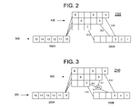
- FIG. 2 is a block diagram of a processor instruction pipeline 200 in accordance with one or more embodiments of the present invention.
- processor instruction pipeline 200 shown in FIG. 2 may be implemented within one or more of the circuits ( 102 - 108 ) of apparatus 100 , discussed above.
- the specific constituent portions of processor instruction pipeline 200 do not necessarily correspond to the respective individual circuits forming apparatus 100 .
- processor instruction pipeline (pipeline) 200 may include main line 300 , branch line 400 , and transfer paths 510 , 520 , and 530 .
- Main line 300 may include main line initial portion 300 A and main line advanced portion 300 B.
- each square in main line 300 and in branch line 400 corresponds to a single “stage” of processor instruction pipeline 200 .
- each instruction advances one stage for each clock cycle of pipeline 200 and processor 100 .
- Branch line 400 may include one or more branch line segments which may include the horizontal arrangements of stages shown in FIG. 2 . Within such segments, as within the portions of main line 300 , the “last stage” (final stage) is the right-most stage, and a more advanced stage is to the right of a less advanced stage.
- transfer paths 510 , 520 , and 530 are paths along which instructions may be transferred from branch line 400 to main line advanced portion 300 B.
- main line initial portion 300 A which in FIG. 2 contains instructions 10 through 15 .
- the instructions in main line initial portion 300 A are preferably dispatched in succession to a selected segment of branch line 400 .
- each segment within branch line 400 may be assigned to one instruction type, a group of instructions having one or more characteristics in common, and/or an instruction set.
- segment selection may be instruction-type-specific and/or instruction-set-specific.
- branch line 400 segments there is generally not a fixed assignment of branch line 400 segments to particular instructions or instruction types. Instead, the association of segments with instructions and/or with groups of related instructions may vary with the operation of pipeline 200 and/or with that of processor 100 .
- instruction 8 is “behind” instruction 7 .
- This terminology is consistent with the forward direction of instruction movement within pipeline 200 being from left to right in FIGS. 2-29 of this application.
- instruction 7 may also be referred to as being a subsequent instruction.
- instruction 8 as a reference point, instruction 7 may be referred to as being a “preceding instruction.”
- branch line 400 segments may be established such that instructions that are more likely to execute wait cycles are directed to the lowest (as illustrated in FIGS. 2-17 ) available branch line 400 segment. Otherwise stated, one or more embodiments of the present invention may operate more efficiently when instructions more likely to execute wait cycles are directed to the shorter branch line 400 segments, which, in the embodiment of FIG. 2 are generally also the “lower” branch line 400 segments. However, in one or more alternative embodiments, branch line 400 segment assignments may deviate from this general principle.
- executing a wait cycle generally corresponds to passively or actively causing an instruction to stand still (remain within the same stage) within pipeline 200 during a clock cycle of pipeline 200 and/or of processor 100 .
- Each instruction may advance one stage per execution cycle within its branch line 400 segment until it reaches the last stage in that segment. In the clock cycle succeeding an instruction's arrival at the final stage of its branch line 400 segment, the instruction may proceed along a transfer path (which may be one of 510 , 520 , and 530 or other path) to the stage in main line advanced portion 300 B at the other end of that transfer path.
- a transfer path which may be one of 510 , 520 , and 530 or other path
- instruction 7 is a wait instruction which is handled in accordance with the embodiment of FIG. 2 .
- instructions advance one stage for each clock cycle within their respective segments of branch line 400 .
- instruction 7 executes two wait cycles and does not move, it may be seen that instruction 8 would advance two stages and end up one segment up, and one stage to the right of instruction 7 .
- instruction 7 would advance to the left-most stage of main line advanced portion 300 B, and instruction 8 would advance to the right-most stage of the middle segment of branch line 400 .
- instruction 7 would advance to the second (from the left) stage of advanced portion 300 B, and instruction 8 would advance to the third (from the left) stage of advanced portion 300 B.
- instructions 7 and 8 would now be located in the wrong order within main line advanced portion 300 B.
- the single-segment structure of advanced portion 300 B may preclude suitably re-ordering these two instructions.
- instructions subsequent to a wait instruction like instruction 7 , generally stop advancing through pipeline 200 once instruction 7 , or any other wait instruction, begins executing one or more wait cycles.
- halting the progress of the subsequent instructions (which are usually higher-numbered instructions) as described may cause one or more execution cycles to be wasted by creating gaps, that is, empty stages, within pipeline 200 .
- a first instruction is “behind” a second instruction when the first instruction is situated to the left of the second in the initial order of instructions within main line initial portion 300 A, as shown in FIG. 2 .
- the left and right directions are used herein for convenience, in connection with the illustrations in the figures. It will be appreciated that the present invention is not limited to any particular spatial relation between adjacent stages of the processor instruction pipelines depicted in the Figures.
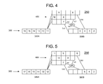
- FIG. 3 is a block diagram of a processor instruction pipeline 250 in accordance with one or more aspects of the present invention.
- Pipeline 250 of FIG. 3 includes many of the same constituent elements as pipeline 200 of FIG. 2 . Accordingly, a list of the common elements is not repeated in this section.
- pipeline 250 of FIG. 3 may include selector 550 and transfer path 540 from branch line 400 to main line advanced portion 300 B.
- a first selection operation may involve having a final stage (right-most stage) in any segment of branch line 400 determine which main line advanced portion 300 B stage an instruction will be transferred to.
- instruction 7 has been transferred from the final stage of the lowest segment of branch line 400 to the third (from the left) stage of main line advanced portion 300 B along transfer path 540 .
- the above-described selection operation may be implemented within the final stage of the bottom segment of branch line 400 using software, hardware, or a combination of the two.
- the first selection operation discussed above may be enabled by including data with each instruction indicating the number, if any, of wait cycles executed by that instruction. Upon acquiring such wait cycle execution data, the first selection operation may cause the pertinent instruction to skip a number of stages within main line advanced portion 300 B that corresponds to the number of executed wait cycles.
- instruction 7 has been transferred from the final stage of the lowest segment of branch line 400 to the third (from the left) stage of main line advanced portion 300 B, thereby skipping two stages within main line advanced portion 300 B.
- the two skipped stages correspond to the two wait cycles executed by instruction 7 while located within branch line 400 .
- the above-described selection operation may be implemented within branch line 400 using software, hardware, or a combination of the two.
- a second selection operation may include having a stage within main line advanced portion 300 B select a source stage from which to receive an instruction, where more than one source stage is available. Selector 550 may perform this function using software, hardware, or a combination of both.
- the four following conditions are preferably satisfied in order for the system of FIG. 3 to operate in a preferred manner.
- the sum of the number of wait cycles executed by the wait instruction (instruction 7 in the system of FIG. 3 ) and the number of stages in the segment the wait instruction is located in preferably does not exceed the number of stages in the longest branch line 400 segment.
- the instruction (instruction 8 in the embodiment of FIG. 3 ) immediately following the wait instruction is preferably not dispatched to the same branch line segment as the wait instruction itself.
- the instructions in the branch line 400 preferably do not depend on data from instructions outside the branch line 400 .
- FIG. 4 shows the state of pipeline 250 one execution cycle later than the state shown in FIG. 3 .
- wait instruction 7 has executed a wait cycle and has not moved.
- the instructions that were initially subsequent to instruction 7 in pipeline 250 have advanced.
- instructions 8 and 9 have moved one stage to the right in their respective branch line 400 segments.
- Instructions 4 and 5 have moved along transfer paths 530 and 520 , respectively, to main line advanced portion 300 B.
- FIG. 5 shows pipeline 250 in a state one execution cycle later than the state shown in FIG. 4 . It may be seen that the instructions in the main line advanced portion 300 B have all advanced. Similarly, it may be seen that the instructions, except for instruction 7 , that were already in branch line 400 , in the state shown in FIG. 4 , have also advanced one stage. Moreover, instruction 11 has moved, or been “dispatched,” from main line initial portion 300 A to branch line 400 . In the pipeline 250 state shown in FIG. 5 , instruction 7 has completed its two wait cycles.
- FIG. 6 shows pipeline 250 one execution cycle later than the state shown in FIG. 5 .
- Instructions 8 - 11 that were already in branch line 400 have advanced one stage in their respective branch line 400 segments, and instruction 12 has advanced from main line initial portion 300 A to branch line 400 .
- the instructions in main line advanced portion 300 B have advanced by one stage, and instruction 6 has advanced along transfer path 530 to the fourth (from the left) stage in main line advanced portion 300 B.
- instruction 7 may advance along transfer path 540 to the third (from the left) execution stage of main line advanced portion 300 B.
- instruction 7 has skipped a number of stages in main line advanced portion 300 B that corresponds to the number of wait cycles it executed while within branch line 400 .
- instruction 7 executed two wait cycles, and has, correspondingly, skipped two stages upon being transferred to main line advanced portion 300 B.
- selector 550 may select which branch line 400 segment final stage to accept an instruction from for transfer to the third stage of main line advanced portion 300 B.
- the final stage of the middle segment of branch line 400 is empty, and the final stage of the lowest segment of branch line 400 contains instruction 7 . Accordingly, in this case the selection is readily made, and selector 550 preferably transfers instruction 7 along transfer path 540 to the third (from the left) stage of main line advanced portion 300 B.
- FIG. 7 shows pipeline 250 one execution cycle after the state shown in FIG. 6 .
- the instructions in pipeline 250 have all advanced according to the principles discussed above. Thus, to avoid repetition, the details of the advancement of each instruction are not repeated here.
- instruction 8 which has advanced along transfer path 520 to the third (from the left) stage of main line advanced portion 300 B. Due to instruction 7 having skipped two stages, as described in connection with FIG. 6 , instruction 8 is now located subsequent to instruction 7 in main line advanced portion 300 B, thereby restoring the original order of these instructions within pipeline 250 . Moreover, it may be seen that instructions 9 and 10 are positioned within branch line 400 such that they will advance along transfer paths 530 and 520 , respectively, and be transferred to main line advanced portion 300 B subsequent to instructions 7 and 8 . This, as well, is consistent with the original order of these instructions in pipeline 250 , that is, the order of the instructions prior to the execution of wait cycles by instruction 7 .
- allowing instructions initially located subsequent to instruction 7 in pipeline 250 (such as instructions 8 , 9 , etc. . . . ) to advance while instruction 7 executed wait cycles, and advancing instruction 7 by extra or additional stages as discussed in connection with FIG. 6 enables pipeline 250 to avoid having wasted execution cycles, while still preserving the original order of the instructions and thereby preserving the integrity of the data processing operations occurring within pipeline 250 .
- one or more embodiments of the present invention may achieve superior processing efficiency than that available employing the embodiment of FIG. 2 .
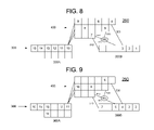
- FIG. 8 is a block diagram of a processor instruction pipeline 260 in accordance with one or more embodiments of the present invention.
- FIG. 9-18 are block diagrams of processor instruction pipeline 260 of FIG. 8 at successive stages of instruction advancement therethrough, in accordance with one or more embodiments of the present invention.
- processor instruction pipeline (pipeline) 260 of FIG. 8 includes the same constituent parts as those described in connection with processor instruction pipeline 250 of FIG. 3 , with the exception that main line initial portion 300 A of pipeline 260 may include a second segment. To avoid needless repetition, the parts in common between the processor pipeline embodiments of FIGS. 3 and 8 are not discussed further herein.
- the second segment, or “lower segment”, of main line initial portion 300 A may have a length that corresponds to the length of the section of the upper segment (first segment) of main line initial portion 300 A that extends from the stage at which a wait instruction executes one or more wait cycles to the stage at which instructions may be dispatched to branch line 400 .
- the pertinent section of the upper segment, and thus the length of the lower segment under discussion are both four stages long.
- the invention is not limited to including a lower segment having a length of four stages, and in alternative embodiments, the lower segment may include fewer or more than four stages. It will be appreciated that the term “below” is used for convenience in describing the embodiment of FIG. 8 .
- the present invention does not require any particular geometric relation between the first and second segments of main line initial portion 300 A, or for that matter, between any segments within any pipeline disclosed herein.
- the following conditions are preferably satisfied in order to enable non-wait instructions to advance while a wait instruction executes wait cycles.
- processing system 100 be aware of the branch line 400 segment that the instruction, that dispatched immediately prior the execution of a wait cycle, will be dispatched to.
- the sum of the number of executed wait cycles and the number of stages in the branch line 400 segment the wait instruction will be in after being dispatched preferably does not exceed the number of stages in the longest branch line segment.
- one or more instructions immediately subsequent to (succeeding) the wait instruction are preferably dispatched to a different branch line 400 segment than the one the wait instruction is dispatched to. More specifically, instructions succeeding the wait instruction, by advancing along the second segment of main line advanced portion 300 A, referred to herein as “bypass instructions” are preferably dispatched to one or more branch line 400 segments other than the one the wait instruction is dispatched to. Dispatching the instructions in this manner preferably enables the wait instruction to advance through and exit branch line 400 ahead of the bypass instructions, thereby restoring and/or maintaining the original order of the instructions.
- each instruction in the second segment of the main line initial portion 300 A is preferably independent of each other instruction in that segment.
- a wait instruction may include data indicative of the number of wait cycles it executed.
- this wait-cycle data may be used to enable the wait instruction to skip a number of stages corresponding to the number of wait cycles executed thereby.
- the instructions in branch line 400 are preferably independent of data and/or operands associated with instructions outside of branch line 400 .
- FIGS. 8-18 illustrate an exemplary flow of instructions through pipeline 260 in accordance with one or more embodiments of the present invention.
- the present invention is not limited to the details of the instruction flow illustrated in the drawings or described in the text below.
- the flow of the instructions preceding the wait instruction 13 occurs in accordance with the general principles discussed earlier in this document, and is therefore not discussed in detail below.
- lower-numbered instructions depart the view of the following FIGS at the right of main line advanced portion 300 B, and sequentially numbered, higher-numbered new instructions are introduced at the left of main line initial portion 300 A.
- the following text does not address the departing or newly introduced instructions in significant detail.
- instructions 1 - 15 are shown within pipeline 260 . It is noted that instruction 13 is a wait instruction and may remain immobile within one stage while executing wait cycles.
- FIG. 9 shows the state of pipeline 260 after instruction 13 has executed a wait cycle. It may be seen that the instructions 1 - 12 have advanced normally.
- the subsequent instructions are provided with a second segment (the lower of two segments of main line initial portion 300 A of FIGS. 8-18 ) of main line initial portion 300 A along which to advance. Accordingly, in the view of FIG. 9 , instruction 14 has preferably advanced along this second segment, while instruction 13 has preferably remained stationary.
- instructions 2 - 12 have advanced normally.
- instruction 13 preferably executes a another wait cycle and preferably remains in the same stage it was in, in the pipeline 260 state shown in FIGS. 8 and 9 .
- Instruction 14 preferably advances along the second segment of main line initial portion 300 A. Moreover, following the path of instruction 14 , instruction 15 preferably moves to the spare line stage just below instruction 13 .
- instructions 3 - 12 have advanced normally. Directing attention to main line initial portion 300 A, it may be seen that instructions 14 and 15 have advanced by one stage each along the second segment of initial portion 300 A. At the same time, instruction 13 , followed by instructions 16 - 18 , has advanced along the upper segment of main line initial portion 300 A.
- instructions 14 and 15 have preferably advanced by one stage each within the lower segment of initial portion 300 A.
- instruction 13 and instructions 16 - 19 have advanced along the upper segment of initial portion 300 A.
- instruction 14 has advanced, or been “dispatched,” from main line initial portion 300 A to branch line 400 .
- Instruction 15 has advanced one stage within the lower segment of initial portion 300 A.
- instructions 13 and 16 - 20 have advanced by one stage each along the upper segment of main line initial portion 300 A.
- instruction 14 is, in some sense, “ahead” of instruction 13 within pipeline 260 in the pipeline state illustrated in FIG. 13 .
- the instruction flow in the following FIGS illustrates how one or more embodiments of the present invention operate to restore an original order of the instructions within pipeline 260 .
- instructions 13 and 15 have now both advanced, or been dispatched, to branch line 400 from main line initial portion 300 A, leaving the second segment of main line initial portion 300 A empty.
- Instruction 14 has advanced within its branch line 400 segment, and instructions 16 - 21 have advanced within main line initial portion 300 A.
- instructions 13 , 14 , and 15 have advanced one stage each within branch line 400 , and instruction 16 has been dispatched to branch line 400 .
- Instructions 17 - 22 have advanced normally within main line initial portion 300 A.
- instructions 13 - 16 have each advanced by one stage within branch line 400 , and instruction 17 has been dispatched to the upper segment of branch line 400 from main line initial portion 300 A.
- instruction 13 preferably advances along transfer path 540 , with the aid of selector 550 , to the third (from the left) stage of main line advanced portion 300 B.
- instructions 14 - 24 have advanced conventionally within pipeline 260 , with instruction 18 being dispatched to the middle segment of branch line 400 .
- a selection operation within the last stage of the lowest segment of branch line 400 may be operable to cause instruction 13 to skip a number of stages, within main line advanced portion 300 B, that corresponds to the number of wait cycles executed by wait instruction 13 .
- instruction 13 executed two wait cycles, and has therefore skipped two stages within main line advanced portion 300 B.
- Selector 550 preferably operates to select from two possible sources within branch line 400 for delivery of an instruction, in this case instruction 13 , to the third stage of main line advanced portion 300 B.
- the first possible source is the final stage of the lowest segment
- the second possible source is the final stage of the middle segment of branch line 400 .
- instruction 13 is located in the lowest segment's final stage, and the middle segment's final stage is empty. Accordingly, the decision is readily made, and selector 550 preferably operates to transfer instruction 13 along transfer path 540 to the third (from the left) stage of main line advanced portion 300 B.
- the instructions initially located subsequent to instruction 13 in pipeline 260 were able to continue advancing through pipeline 260 during instruction 13 's wait cycles, and a system and method in accordance with one or more embodiments of the present invention was able to restore the order of the instructions that prevailed prior to the execution of the wait instructions.
- the original order of the instructions was preserved while providing computational efficiency by keeping main line advanced portion 300 B fully supplied with instructions (that is, avoiding any gaps in the pipeline) throughout the instruction advancement sequence shown in FIGS. 8-17 .
- wait cycles executed by wait instructions located in the initial and advanced portions of a main line are performed separately, causing the progress of both types of instructions through a processor instruction pipeline to stop.
- This practice imposes a burden on the processing efficiency the pipeline. Accordingly, it would be desirable to provide a more efficient method for handling wait cycles in a processor instruction pipeline.
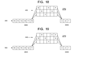
- FIG. 18 is a block diagram of a processor instruction pipeline 270 in accordance with one or more embodiments of the present invention.
- FIGS. 19-29 are block diagrams of the processor instruction pipeline 270 of FIG. 18 at successive stages of instruction advancement therethrough in accordance with one or more embodiments of the present invention.
- processor instruction pipeline 270 may include main line 350 and branch line 450 .
- Main line 350 may include main line initial portion 350 A and main line advanced portion 350 B.
- suitable connections are provided between main line initial portion 350 A and branch line 450 , and between branch line 450 and main line advanced portion 350 B.
- FIGS. 18-29 show branch line 450 having segments of equal length, segments of equal or of unequal length may be both used within with one or more embodiments of the present invention.
- wait cycles may be concurrently executed by one or more wait instructions in the main line initial portion 350 A and by one or more wait instructions in main line advanced portion 350 B. Instructions located in between the two concurrently executing wait instructions may be buffered within branch line 450 . Proceeding in this manner preferably avoids wasting execution cycles within pipeline 270 .
- processor instruction pipeline 270 in accordance with one or more embodiments of the present invention.
- instruction sequence number information is preferably associated with each instruction to enable the transfer of instructions from the branch line 450 to the main line 350 in the proper order.
- branch line 450 preferably do not depend on data from instructions located outside branch line 450 .
- branch line 450 may leave branch line 450 until the dependency is resolved.
- FIG. 18 shows pipeline 270 with instructions disposed therein in an initial order, and numbered consecutively from 1 to 15.
- FIGS. 19-29 show pipeline 270 at the conclusion of successive instruction execution cycles. It is noted that the FIGS. 18-29 demonstrate an example of the operation of one or more embodiments of the present invention and that the present invention is not limited to the specific sequence of wait cycles, instruction movements, and/or instruction numbers illustrated therein.
- instructions continue advancing one stage to the right for each clock cycle of pipeline 270 until a stage adjacent to stage having another instruction therein is reached, or until the final stage in that branch line 450 segment is reached.
- instructions are not necessarily transferred from branch line 450 to main line 350 one cycle after reaching the final stage within a branch line 450 segment.
- the decision whether or not to transfer a given instruction in a final branch line 450 stage may depend upon a) the availability of an empty stage within main line advanced stage 350 B and b) the sequence number of the given instruction in comparison with the sequence number of one or more other instructions that are available for transfer to main line advanced portion 350 B.
- the foregoing instruction advancement discussion is applicable to one or more embodiments illustrated in FIGS. 18-29 .
- FIG. 18 shows an initial sequence of instructions within pipeline 270 .
- a total of six instructions are disposed within branch line 450 in the pipeline 270 condition shown in FIG. 18 .
- main line advanced portion 350 B have not advanced, due to instruction 1 executing a wait cycle. However, the instructions in main line initial portion 350 A have advanced, as have most of the instructions in branch line 450 .
- both instructions 1 and 14 have executed wait cycles in the preceding pipeline 270 cycle.
- instructions ahead of (lower-numbered than) instruction 14 in main line initial portion 350 A have advanced, instructions located subsequent to instruction 14 will preferably remain stationary until instruction 14 stops executing wait cycles.
- Instruction 11 has been dispatched from main line initial portion 350 A to branch line 450 , and instructions 12 and 13 have advanced within main line initial portion 350 A.
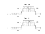
- instructions numbered 14 and higher remain stationary within main line initial portion 350 A as do instructions 1 - 3 in main line advanced portion 350 B. This lack of advancement is due to the execution of wait cycles by both instruction 1 and instruction 14 .
- instruction 12 has been dispatched to branch line 450 , and instructions within branch line 450 that had empty stages to advance into, have also advanced by one stage. It is noted that in the pipeline 270 state depicted in FIG. 21 , there are nine instructions in branch line 450 .
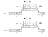
- the association of instruction sequence number information with each instruction preferably enables the system governing the advancement of instructions in pipeline 270 to select instruction 4 for transfer to main line advanced portion 350 B from branch line 450 , as shown in FIG. 22 .
- This instruction sequence number information is preferably employed for all such instruction transfers from branch line 450 to main line advanced portion 350 B to preserve and/or restore the initial order of instructions within main line 350 and thus in processor instruction pipeline 270 .
- instructions 14 - 17 (where instruction 17 is newly introduced into the portion of pipeline 270 visible in FIG. 22 ) have advanced within main line initial portion 350 A. And instruction 13 has been dispatched from main line initial portion 350 A to branch line 450 .
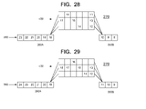
- pipeline 270 effectively employs branch line 450 as a F.I.F.O. (First-In, First-Out) buffer for instructions dispatched thereto during execution of the wait cycles by wait instructions 1 and 14 and thereby preferably avoids wasting execution cycles within pipeline 270 .
- F.I.F.O. First-In, First-Out
- main line advanced portion 300 B fully supplied with instructions (that is, avoiding any gaps in the pipeline) throughout the instruction advancement sequence shown in FIGS. 18-29 .
Abstract
A system and method are disclosed which may include providing a processor instruction pipeline having a main line and a branch line; executing at least one wait cycle for at least one wait instruction in said pipeline; and advancing at least selected instructions, that are initially located subsequent to at least one wait instruction in said pipeline, through the pipeline during the at least one wait cycle.
Description
- The present invention relates to methods and apparatus for improving the efficiency of processor instruction pipeline within a pipelined processing system.
- In recent years, there has been an insatiable desire for faster computer processing data throughputs because cutting edge computer applications involve real time, multimedia functionality. Graphics applications are among those that place the highest demands on a processing system because they require such vast numbers of data accesses, data computations, and data manipulations in relatively short periods of time to achieve desirable visual results. These applications require extremely fast processing speeds, such as many thousands of megabits of data per second.
- Processors may employ pipelining to improve performance in light of the ever-increasing demands for processor performance. The execution of any instruction typically includes several distinct stages. Pipelining enables some or all of these stages to be acted upon concurrently, rather than consecutively, thereby expediting the processing of instructions through a processor. However, pipelining can be hindered by a lack of ideal synchronization of various concurrent tasks. Specifically, pipelining may be limited by the need by some instructions to access data produced by the completion of other instructions, when the data is not yet ready. Such situations can lead to wasted execution cycles within a processor pipeline. Accordingly, there is a need in the art for improved efficiency within processor pipelines.
- According to one aspect, the present invention provides methods and apparatus that may include providing a processor instruction pipeline having a main line and a branch line; executing at least one wait cycle for at least one wait instruction in the pipeline; and advancing at least selected instructions, that are initially located subsequent to at least one wait instruction in the pipeline, through the pipeline during the at least one wait cycle.
- According to another aspect, the present invention provides methods and apparatus that may include providing a processor instruction pipeline having a main line and a branch line, the main line having initial and advanced portions; disposing a plurality of instructions within the pipeline; advancing the instructions from a first portion of the main line to the branch line and then to the second portion of the main line; executing at least one wait cycle by a wait instruction, of the instructions, in the pipeline; and advancing given ones of the instructions, that are initially located subsequent to the wait instruction in the pipeline, through the pipeline during execution of the at least one wait cycle.
- According to yet another aspect, the present invention provides methods and apparatus that may include a) providing a processor instruction pipeline having a main line having an initial portion and an advanced portion and a branch line disposed between the initial portion and the advanced portion; b) disposing instructions within the processor instruction pipeline in an initial order; c) executing at least one wait cycle by at least one wait instruction in the main line advanced portion; d) executing at least one wait cycle by at least one wait instruction in the main line initial portion, the execution of steps c) and d) occurring concurrently; and e) buffering a selection of the instructions in the branch line during the concurrent execution steps.
- Other aspects, features, advantages, etc. will become apparent to one skilled in the art when the description of the preferred embodiments of the invention herein is taken in conjunction with the accompanying drawings.
- For the purposes of illustrating the various aspects of the invention, there are shown in the drawings forms that are presently preferred, it being understood, however, that the invention is not limited to the precise arrangements and instrumentalities shown.
-
FIG. 1 is a block diagram illustrating the structure of a processing system that may be used in accordance with one or more aspects of the present invention; -
FIG. 2 is a block diagram of a processor instruction pipeline in accordance with one or more aspects of the present invention; -
FIG. 3 is a block diagram of a processor instruction pipeline in accordance with one or more aspects of the present invention; -
FIGS. 4-7 are block diagrams of the processor instruction pipeline ofFIG. 3 at successive stages of instruction advancement therethrough in accordance with one or more embodiments of the present invention; -
FIG. 8 is a block diagram of a processor instruction pipeline in accordance with one or more other embodiments of the present invention; -
FIG. 9-18 are block diagrams of the processor instruction pipeline ofFIG. 8 at successive stages of instruction advancement therethrough, in accordance with one or more embodiments of the present invention; -
FIG. 18 is a block diagram of a processor instruction pipeline in accordance with one or more embodiments of the present invention; -
FIGS. 19-29 are block diagrams of the processor instruction pipeline ofFIG. 18 at successive stages of instruction advancement therethrough in accordance with one or more embodiments of the present invention; - With reference to the drawings, wherein like numerals indicate like elements, there is shown in
FIG. 1 at least a portion of a processing system (processor) 100 that may be adapted for carrying out one or more features of the present invention. For the purposes of brevity and clarity, the block diagram ofFIG. 1 will be referred to and described herein as illustrating anapparatus 100, it being understood, however, that the description may readily be applied to various aspects of a method with equal force. - The
processing system 100 is preferably implemented using a processing pipeline, in which logic instructions are processed in a pipelined fashion. Although the pipeline may be divided into any number of stages at which instructions are processed, the pipeline generally comprises fetching one or more instructions, decoding the instructions, checking for dependencies among the instructions, issuing the instructions, and executing the instructions. In this regard, theprocessing system 100 may include an instruction buffer (not shown), aninstruction fetch circuit 102, aninstruction decode circuit 104, adependency check circuit 106, instruction issue circuitry (not shown), andinstruction execution stages 108. - The
instruction fetch circuitry 102 is preferably operable to facilitate the transfer of one or more instructions from a memory to the instruction buffer, where the instructions are queued up for release into the pipeline. The instruction buffer may include a plurality of registers that are operable to temporarily store instructions as they are fetched. Theinstruction decode circuit 104 is adapted to break down the instructions and generate logical micro-operations that perform the function of the corresponding instruction. For example, the logical micro-operations may specify arithmetic and logical operations, load and store operations to the memory, register source operands and/or immediate data operands. Theinstruction decode circuit 104 may also indicate which resources the instruction uses, such as target register addresses, structural resources, function units and/or busses. Theinstruction decode circuit 104 may also supply information indicating the instruction pipeline stages in which the resources are required. - The
dependency check circuit 106 includes a plurality of registers, where one or more registers are associated with each execution stage of the pipeline. The registers store indications (identification numbers, register numbers, etc.) of the operands of the instructions being executed in the pipeline. Thedependency check circuit 106 also includes digital logic that performs testing to determine whether the operands of an instruction for entry into the pipeline are dependent on the operands of other instructions already in the pipeline. If so, then the given instruction should not be executed until such other operands are updated (e.g., by permitting the other instructions to complete execution). - The
instruction execution circuitry 108 preferably includes a plurality of floating point and/or fixed point execution stages to execute arithmetic instructions. Depending upon the required processing power, a greater or lesser number of floating point execution stages and fixed point execution stages may be employed. It is most preferred that the instruction execution circuitry 108 (as well as the other circuits of the processing system 100) is of a superscalar architecture, such that more than one instruction is issued and executed per clock cycle. With reference to any given instruction, however, theexecution circuitry 108 executes the instructions in a number of stages, where each stage takes one or more clock cycles, usually one clock cycle. -
FIG. 2 is a block diagram of aprocessor instruction pipeline 200 in accordance with one or more embodiments of the present invention. - In one or more embodiments, the various portions of
processor instruction pipeline 200 shown inFIG. 2 , and discussed below, may be implemented within one or more of the circuits (102-108) ofapparatus 100, discussed above. However, the specific constituent portions ofprocessor instruction pipeline 200 do not necessarily correspond to the respective individualcircuits forming apparatus 100. - In one or more embodiments, processor instruction pipeline (pipeline) 200 may include
main line 300,branch line 400, andtransfer paths Main line 300 may include main lineinitial portion 300A and main lineadvanced portion 300B. Preferably, each square inmain line 300 and inbranch line 400 corresponds to a single “stage” ofprocessor instruction pipeline 200. Preferably, each instruction advances one stage for each clock cycle ofpipeline 200 andprocessor 100. -
Branch line 400 may include one or more branch line segments which may include the horizontal arrangements of stages shown inFIG. 2 . Within such segments, as within the portions ofmain line 300, the “last stage” (final stage) is the right-most stage, and a more advanced stage is to the right of a less advanced stage. - In one or more embodiments,
transfer paths branch line 400 to main lineadvanced portion 300B. - To aid in describing one or more embodiments of the invention, a description a conventional flow of instructions through
pipeline 200 is provided here. Instructions may be queued in main line initial portion (initial portion) 300A, which inFIG. 2 containsinstructions 10 through 15. The instructions in main lineinitial portion 300A are preferably dispatched in succession to a selected segment ofbranch line 400. In one or more embodiments, each segment withinbranch line 400 may be assigned to one instruction type, a group of instructions having one or more characteristics in common, and/or an instruction set. Thus, segment selection may be instruction-type-specific and/or instruction-set-specific. However, there is generally not a fixed assignment ofbranch line 400 segments to particular instructions or instruction types. Instead, the association of segments with instructions and/or with groups of related instructions may vary with the operation ofpipeline 200 and/or with that ofprocessor 100. - For the sake of clarity herein, we assign names for the relative locations of instructions within
pipeline 200. Given instructions slated for passage throughpipeline 200 after other instructions are considered to be “behind” the other instructions. The given instructions themselves may be referred to as “subsequent instructions” in relation to the other instructions. The “other instructions” referred to above are referred to as being “ahead of”, “in front of” and/or “forward of” the given instructions. The other instructions themselves may be referred to as “preceding instructions” in relation to the given instructions. - For example, in
FIG. 2 ,instruction 8 is “behind”instruction 7. This terminology is consistent with the forward direction of instruction movement withinpipeline 200 being from left to right inFIGS. 2-29 of this application. Withinstruction 7 as a reference point,instruction 8 may also be referred to as being a subsequent instruction. Withinstruction 8 as a reference point,instruction 7 may be referred to as being a “preceding instruction.” - The assignment of
branch line 400 segments to instructions and/or instruction types may be established such that instructions that are more likely to execute wait cycles are directed to the lowest (as illustrated inFIGS. 2-17 )available branch line 400 segment. Otherwise stated, one or more embodiments of the present invention may operate more efficiently when instructions more likely to execute wait cycles are directed to theshorter branch line 400 segments, which, in the embodiment ofFIG. 2 are generally also the “lower”branch line 400 segments. However, in one or more alternative embodiments,branch line 400 segment assignments may deviate from this general principle. - Herein, executing a wait cycle generally corresponds to passively or actively causing an instruction to stand still (remain within the same stage) within
pipeline 200 during a clock cycle ofpipeline 200 and/or ofprocessor 100. - Each instruction may advance one stage per execution cycle within its
branch line 400 segment until it reaches the last stage in that segment. In the clock cycle succeeding an instruction's arrival at the final stage of itsbranch line 400 segment, the instruction may proceed along a transfer path (which may be one of 510, 520, and 530 or other path) to the stage in main lineadvanced portion 300B at the other end of that transfer path. The foregoing is generally applicable to the embodiments illustrated inFIGS. 2-17 . - In order to illustrate the operation of one or more embodiments of the present invention, an example is considered in which
instruction 7, as shown inFIG. 2 , is a wait instruction which is handled in accordance with the embodiment ofFIG. 2 . - Typically, instructions advance one stage for each clock cycle within their respective segments of
branch line 400. Thus, ifinstruction 7 executes two wait cycles and does not move, it may be seen thatinstruction 8 would advance two stages and end up one segment up, and one stage to the right ofinstruction 7. One cycle later,instruction 7 would advance to the left-most stage of main lineadvanced portion 300B, andinstruction 8 would advance to the right-most stage of the middle segment ofbranch line 400. Another cycle later,instruction 7 would advance to the second (from the left) stage ofadvanced portion 300B, andinstruction 8 would advance to the third (from the left) stage ofadvanced portion 300B. - Thus,
instructions advanced portion 300B. And, in the exemplary embodiment ofFIG. 2 , the single-segment structure ofadvanced portion 300B may preclude suitably re-ordering these two instructions. - To avoid the problem of improper ordering of instructions described above, instructions subsequent to a wait instruction, like
instruction 7, generally stop advancing throughpipeline 200 onceinstruction 7, or any other wait instruction, begins executing one or more wait cycles. However, halting the progress of the subsequent instructions (which are usually higher-numbered instructions) as described may cause one or more execution cycles to be wasted by creating gaps, that is, empty stages, withinpipeline 200. Herein, a first instruction is “behind” a second instruction when the first instruction is situated to the left of the second in the initial order of instructions within main lineinitial portion 300A, as shown inFIG. 2 . The left and right directions are used herein for convenience, in connection with the illustrations in the figures. It will be appreciated that the present invention is not limited to any particular spatial relation between adjacent stages of the processor instruction pipelines depicted in the Figures. - Accordingly, it would be desirable to enable instructions located behind a wait instruction in
pipeline 200 to keep moving during the execution of one or more wait cycles by the wait instruction, without causing the instructions to be placed in main lineadvanced portion 300B in an incorrect order. - The following provides a discussion of various embodiments in which instructions initially located behind a wait instruction in a processor instruction pipeline may continue advancing during the execution of wait cycles, while still enabling the initial order (original order) of the instructions within the pipeline to be preserved and/or restored.
-
FIG. 3 is a block diagram of aprocessor instruction pipeline 250 in accordance with one or more aspects of the present invention.Pipeline 250 ofFIG. 3 includes many of the same constituent elements aspipeline 200 ofFIG. 2 . Accordingly, a list of the common elements is not repeated in this section. - In addition to the elements recited in connection with
pipeline 200 ofFIG. 2 ,pipeline 250 ofFIG. 3 may includeselector 550 and transferpath 540 frombranch line 400 to main lineadvanced portion 300B. - In one or more embodiments, two or more selection operations may be performed within
pipeline 250. A first selection operation may involve having a final stage (right-most stage) in any segment ofbranch line 400 determine which main lineadvanced portion 300B stage an instruction will be transferred to. By way of example, it may be seen that between the state shown inFIG. 5 and that shown inFIG. 6 ,instruction 7 has been transferred from the final stage of the lowest segment ofbranch line 400 to the third (from the left) stage of main lineadvanced portion 300B alongtransfer path 540. The above-described selection operation may be implemented within the final stage of the bottom segment ofbranch line 400 using software, hardware, or a combination of the two. - In one or more embodiments, the first selection operation discussed above may be enabled by including data with each instruction indicating the number, if any, of wait cycles executed by that instruction. Upon acquiring such wait cycle execution data, the first selection operation may cause the pertinent instruction to skip a number of stages within main line
advanced portion 300B that corresponds to the number of executed wait cycles. - By way of example, it may be seen that between the state shown in
FIG. 5 and that shown inFIG. 6 ,instruction 7 has been transferred from the final stage of the lowest segment ofbranch line 400 to the third (from the left) stage of main lineadvanced portion 300B, thereby skipping two stages within main lineadvanced portion 300B. As discussed later herein, the two skipped stages correspond to the two wait cycles executed byinstruction 7 while located withinbranch line 400. The above-described selection operation may be implemented withinbranch line 400 using software, hardware, or a combination of the two. - In one or more embodiments, a second selection operation may include having a stage within main line
advanced portion 300B select a source stage from which to receive an instruction, where more than one source stage is available.Selector 550 may perform this function using software, hardware, or a combination of both. - In one or more embodiments, the four following conditions are preferably satisfied in order for the system of
FIG. 3 to operate in a preferred manner. - The sum of the number of wait cycles executed by the wait instruction (
instruction 7 in the system ofFIG. 3 ) and the number of stages in the segment the wait instruction is located in preferably does not exceed the number of stages in thelongest branch line 400 segment. - The instruction (
instruction 8 in the embodiment ofFIG. 3 ) immediately following the wait instruction is preferably not dispatched to the same branch line segment as the wait instruction itself. - Once it is determined that a wait instruction will begin executing one or more wait cycles,
pipeline 250 preferably discontinues dispatching instructions to thebranch line 400 segment that wait instruction is in. - The instructions in the
branch line 400 preferably do not depend on data from instructions outside thebranch line 400. - The following discusses the operation of the embodiment of
FIG. 3 when faced with the same initial conditions as those described above in connection withFIG. 2 . Specifically, the embodiment ofFIG. 3 begins with the same instructions located in the same respective stages of the pipeline (which ispipeline 250 in the case ofFIG. 3 ) as was the case withFIG. 2 . Moreover, the sequence of events discussed in connection withFIG. 3 starts withinstruction 7 executing two consecutive wait cycles (wait instructions).FIGS. 4-7 show the apparatus ofFIG. 3 at successive stages of instruction advancement throughpipeline 250, in accordance with one or more embodiments of the present invention. - It will be understood by those of ordinary skill in the art that the following is an example of instruction advancement through
pipeline 250 employing one or more embodiments of the present invention, and that the present invention is not limited to the specific exemplary instruction flow. - Continuing with the example,
FIG. 4 shows the state ofpipeline 250 one execution cycle later than the state shown inFIG. 3 . During this cycle, waitinstruction 7 has executed a wait cycle and has not moved. It may be seen that in this embodiment, the instructions that were initially subsequent toinstruction 7 inpipeline 250 have advanced. Specifically,instructions respective branch line 400 segments.Instructions transfer paths advanced portion 300B. - Continuing with the example,
FIG. 5 showspipeline 250 in a state one execution cycle later than the state shown inFIG. 4 . It may be seen that the instructions in the main lineadvanced portion 300B have all advanced. Similarly, it may be seen that the instructions, except forinstruction 7, that were already inbranch line 400, in the state shown inFIG. 4 , have also advanced one stage. Moreover,instruction 11 has moved, or been “dispatched,” from main lineinitial portion 300A tobranch line 400. In thepipeline 250 state shown inFIG. 5 ,instruction 7 has completed its two wait cycles. - Continuing with the example,
FIG. 6 showspipeline 250 one execution cycle later than the state shown inFIG. 5 . Instructions 8-11 that were already inbranch line 400 have advanced one stage in theirrespective branch line 400 segments, andinstruction 12 has advanced from main lineinitial portion 300A tobranch line 400. Moreover, the instructions in main lineadvanced portion 300B have advanced by one stage, andinstruction 6 has advanced alongtransfer path 530 to the fourth (from the left) stage in main lineadvanced portion 300B. - In one or more embodiments of the present invention,
instruction 7 may advance alongtransfer path 540 to the third (from the left) execution stage of main lineadvanced portion 300B. Preferably,instruction 7 has skipped a number of stages in main lineadvanced portion 300B that corresponds to the number of wait cycles it executed while withinbranch line 400. In this example, as discussed earlier,instruction 7 executed two wait cycles, and has, correspondingly, skipped two stages upon being transferred to main lineadvanced portion 300B. - In one or more embodiments,
selector 550 may select whichbranch line 400 segment final stage to accept an instruction from for transfer to the third stage of main lineadvanced portion 300B. In thepipeline 250 state shown inFIG. 5 , the final stage of the middle segment ofbranch line 400 is empty, and the final stage of the lowest segment ofbranch line 400 containsinstruction 7. Accordingly, in this case the selection is readily made, andselector 550 preferably transfersinstruction 7 alongtransfer path 540 to the third (from the left) stage of main lineadvanced portion 300B. - Continuing with the example,
FIG. 7 showspipeline 250 one execution cycle after the state shown inFIG. 6 . The instructions inpipeline 250 have all advanced according to the principles discussed above. Thus, to avoid repetition, the details of the advancement of each instruction are not repeated here. - However, attention is directed to
instruction 8 which has advanced alongtransfer path 520 to the third (from the left) stage of main lineadvanced portion 300B. Due toinstruction 7 having skipped two stages, as described in connection withFIG. 6 ,instruction 8 is now located subsequent toinstruction 7 in main lineadvanced portion 300B, thereby restoring the original order of these instructions withinpipeline 250. Moreover, it may be seen thatinstructions branch line 400 such that they will advance alongtransfer paths advanced portion 300B subsequent toinstructions pipeline 250, that is, the order of the instructions prior to the execution of wait cycles byinstruction 7. - In one or more embodiments, allowing instructions initially located subsequent to
instruction 7 in pipeline 250 (such asinstructions instruction 7 executed wait cycles, and advancinginstruction 7 by extra or additional stages as discussed in connection withFIG. 6 enablespipeline 250 to avoid having wasted execution cycles, while still preserving the original order of the instructions and thereby preserving the integrity of the data processing operations occurring withinpipeline 250. In this manner, one or more embodiments of the present invention may achieve superior processing efficiency than that available employing the embodiment ofFIG. 2 . -
FIG. 8 is a block diagram of aprocessor instruction pipeline 260 in accordance with one or more embodiments of the present invention.FIG. 9-18 are block diagrams ofprocessor instruction pipeline 260 ofFIG. 8 at successive stages of instruction advancement therethrough, in accordance with one or more embodiments of the present invention. - In one or more embodiments, processor instruction pipeline (pipeline) 260 of
FIG. 8 includes the same constituent parts as those described in connection withprocessor instruction pipeline 250 ofFIG. 3 , with the exception that main lineinitial portion 300A ofpipeline 260 may include a second segment. To avoid needless repetition, the parts in common between the processor pipeline embodiments ofFIGS. 3 and 8 are not discussed further herein. - The second segment, or “lower segment”, of main line
initial portion 300A may have a length that corresponds to the length of the section of the upper segment (first segment) of main lineinitial portion 300A that extends from the stage at which a wait instruction executes one or more wait cycles to the stage at which instructions may be dispatched tobranch line 400. In theexemplary pipeline 260 ofFIG. 8 , the pertinent section of the upper segment, and thus the length of the lower segment under discussion are both four stages long. However, the invention is not limited to including a lower segment having a length of four stages, and in alternative embodiments, the lower segment may include fewer or more than four stages. It will be appreciated that the term “below” is used for convenience in describing the embodiment ofFIG. 8 . The present invention does not require any particular geometric relation between the first and second segments of main lineinitial portion 300A, or for that matter, between any segments within any pipeline disclosed herein. - In the following discussion, which address
FIGS. 8-18 , the case in which a wait instruction executes wait cycles while in main lineinitial portion 300A is considered. As with the embodiment discussed in connection withFIGS. 3-7 , the embodiments discussed below may beneficially enable instructions that are initially located subsequent to a wait instruction inprocessor instruction pipeline 260 to keep moving throughpipeline 260 while a wait instruction, in thiscase instruction 13, executes wait cycles. - In one or more embodiments, the following conditions are preferably satisfied in order to enable non-wait instructions to advance while a wait instruction executes wait cycles.
- In one or more embodiments, it is preferred that
processing system 100 be aware of thebranch line 400 segment that the instruction, that dispatched immediately prior the execution of a wait cycle, will be dispatched to. - In one or more embodiments, the sum of the number of executed wait cycles and the number of stages in the
branch line 400 segment the wait instruction will be in after being dispatched preferably does not exceed the number of stages in the longest branch line segment. - In one or more embodiments, one or more instructions immediately subsequent to (succeeding) the wait instruction are preferably dispatched to a
different branch line 400 segment than the one the wait instruction is dispatched to. More specifically, instructions succeeding the wait instruction, by advancing along the second segment of main line advancedportion 300A, referred to herein as “bypass instructions” are preferably dispatched to one ormore branch line 400 segments other than the one the wait instruction is dispatched to. Dispatching the instructions in this manner preferably enables the wait instruction to advance through andexit branch line 400 ahead of the bypass instructions, thereby restoring and/or maintaining the original order of the instructions. - In one or more embodiments, each instruction in the second segment of the main line
initial portion 300A is preferably independent of each other instruction in that segment. - In one or more embodiments, a wait instruction may include data indicative of the number of wait cycles it executed. When the wait instruction is transferred to main line
advanced portion 300B frombranch line 400, this wait-cycle data may be used to enable the wait instruction to skip a number of stages corresponding to the number of wait cycles executed thereby. - In one or more embodiments, the instructions in
branch line 400 are preferably independent of data and/or operands associated with instructions outside ofbranch line 400. - As the apparatus is the same throughout
FIGS. 8-18 , the following discussion is directed to the instruction flow throughpipeline 260. The general principles governing the flow of instructions throughmain line 300 and thebranch line 400 segments was discussed above in connection withFIG. 2 . Accordingly, to avoid repetition, that discussion is not repeated in this section. - It is noted that
FIGS. 8-18 illustrate an exemplary flow of instructions throughpipeline 260 in accordance with one or more embodiments of the present invention. The present invention is not limited to the details of the instruction flow illustrated in the drawings or described in the text below. In general, the flow of the instructions preceding thewait instruction 13 occurs in accordance with the general principles discussed earlier in this document, and is therefore not discussed in detail below. Moreover, in general, lower-numbered instructions depart the view of the following FIGS at the right of main lineadvanced portion 300B, and sequentially numbered, higher-numbered new instructions are introduced at the left of main lineinitial portion 300A. As such instruction flow is considered routine, the following text does not address the departing or newly introduced instructions in significant detail. - In
FIG. 8 , instructions 1-15 are shown withinpipeline 260. It is noted thatinstruction 13 is a wait instruction and may remain immobile within one stage while executing wait cycles. - In one or more embodiments,
FIG. 9 shows the state ofpipeline 260 afterinstruction 13 has executed a wait cycle. It may be seen that the instructions 1-12 have advanced normally. - In one or more embodiments, to avoid having instructions initially located subsequent to
instruction 13 inpipeline 260 halt their advancement during the execution of wait cycles byinstruction 13, the subsequent instructions are provided with a second segment (the lower of two segments of main lineinitial portion 300A ofFIGS. 8-18 ) of main lineinitial portion 300A along which to advance. Accordingly, in the view ofFIG. 9 ,instruction 14 has preferably advanced along this second segment, whileinstruction 13 has preferably remained stationary. - Directing attention to
FIG. 10 , it may be seen that instructions 2-12 have advanced normally. In the cycle the conclusion of which is shown inFIG. 10 ,instruction 13 preferably executes a another wait cycle and preferably remains in the same stage it was in, in thepipeline 260 state shown inFIGS. 8 and 9 . -
Instruction 14 preferably advances along the second segment of main lineinitial portion 300A. Moreover, following the path ofinstruction 14,instruction 15 preferably moves to the spare line stage just belowinstruction 13. - In the cycle the conclusion of which is shown in
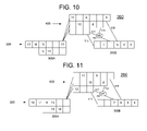
FIG. 11 , instructions 3-12 have advanced normally. Directing attention to main lineinitial portion 300A, it may be seen thatinstructions initial portion 300A. At the same time,instruction 13, followed by instructions 16-18, has advanced along the upper segment of main lineinitial portion 300A. - Turning to
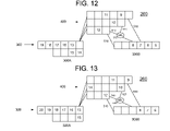
FIG. 12 , and directing attention to main lineinitial portion 300A,instructions initial portion 300A. At the same time,instruction 13 and instructions 16-19 have advanced along the upper segment ofinitial portion 300A. - Attention is now directed to
FIG. 13 . It may be seen thatinstruction 14 has advanced, or been “dispatched,” from main lineinitial portion 300A tobranch line 400.Instruction 15 has advanced one stage within the lower segment ofinitial portion 300A. Andinstructions 13 and 16-20 have advanced by one stage each along the upper segment of main lineinitial portion 300A. - It is noted that
instruction 14 is, in some sense, “ahead” ofinstruction 13 withinpipeline 260 in the pipeline state illustrated inFIG. 13 . The instruction flow in the following FIGS illustrates how one or more embodiments of the present invention operate to restore an original order of the instructions withinpipeline 260. - Directing attention to
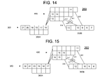
FIG. 14 ,instructions branch line 400 from main lineinitial portion 300A, leaving the second segment of main lineinitial portion 300A empty.Instruction 14 has advanced within itsbranch line 400 segment, and instructions 16-21 have advanced within main lineinitial portion 300A. - Directing attention to
FIG. 15 ,instructions branch line 400, andinstruction 16 has been dispatched tobranch line 400. Instructions 17-22 have advanced normally within main lineinitial portion 300A. - Directing attention to
FIG. 16 , instructions 13-16 have each advanced by one stage withinbranch line 400, andinstruction 17 has been dispatched to the upper segment ofbranch line 400 from main lineinitial portion 300A. - Directing attention to
FIG. 17 ,instruction 13 preferably advances alongtransfer path 540, with the aid ofselector 550, to the third (from the left) stage of main lineadvanced portion 300B. Separately, instructions 14-24 have advanced conventionally withinpipeline 260, withinstruction 18 being dispatched to the middle segment ofbranch line 400. - In one or more embodiments, a selection operation within the last stage of the lowest segment of
branch line 400 may be operable to causeinstruction 13 to skip a number of stages, within main lineadvanced portion 300B, that corresponds to the number of wait cycles executed bywait instruction 13. In this case,instruction 13 executed two wait cycles, and has therefore skipped two stages within main lineadvanced portion 300B. -
Selector 550 preferably operates to select from two possible sources withinbranch line 400 for delivery of an instruction, in thiscase instruction 13, to the third stage of main lineadvanced portion 300B. The first possible source is the final stage of the lowest segment, and the second possible source is the final stage of the middle segment ofbranch line 400. In thepipeline 260 state shown inFIG. 16 ,instruction 13 is located in the lowest segment's final stage, and the middle segment's final stage is empty. Accordingly, the decision is readily made, andselector 550 preferably operates to transferinstruction 13 alongtransfer path 540 to the third (from the left) stage of main lineadvanced portion 300B. - In the above example, the instructions initially located subsequent to
instruction 13 inpipeline 260 were able to continue advancing throughpipeline 260 duringinstruction 13's wait cycles, and a system and method in accordance with one or more embodiments of the present invention was able to restore the order of the instructions that prevailed prior to the execution of the wait instructions. Thus, the original order of the instructions was preserved while providing computational efficiency by keeping main lineadvanced portion 300B fully supplied with instructions (that is, avoiding any gaps in the pipeline) throughout the instruction advancement sequence shown inFIGS. 8-17 . - Generally, wait cycles executed by wait instructions located in the initial and advanced portions of a main line are performed separately, causing the progress of both types of instructions through a processor instruction pipeline to stop. This practice imposes a burden on the processing efficiency the pipeline. Accordingly, it would be desirable to provide a more efficient method for handling wait cycles in a processor instruction pipeline.
-
FIG. 18 is a block diagram of aprocessor instruction pipeline 270 in accordance with one or more embodiments of the present invention.FIGS. 19-29 are block diagrams of theprocessor instruction pipeline 270 ofFIG. 18 at successive stages of instruction advancement therethrough in accordance with one or more embodiments of the present invention. - In one or more embodiments,
processor instruction pipeline 270 may includemain line 350 andbranch line 450.Main line 350 may include main lineinitial portion 350A and main lineadvanced portion 350B. Preferably, suitable connections (transfer paths) are provided between main lineinitial portion 350A andbranch line 450, and betweenbranch line 450 and main lineadvanced portion 350B. WhileFIGS. 18-29 show branch line 450 having segments of equal length, segments of equal or of unequal length may be both used within with one or more embodiments of the present invention. - In one or more embodiments of the present invention, wait cycles may be concurrently executed by one or more wait instructions in the main line
initial portion 350A and by one or more wait instructions in main lineadvanced portion 350B. Instructions located in between the two concurrently executing wait instructions may be buffered withinbranch line 450. Proceeding in this manner preferably avoids wasting execution cycles withinpipeline 270. - The following constraints are preferably satisfied to enable operation of
processor instruction pipeline 270 in accordance with one or more embodiments of the present invention. - In this embodiment, instruction sequence number information is preferably associated with each instruction to enable the transfer of instructions from the
branch line 450 to themain line 350 in the proper order. - The instructions in
branch line 450 preferably do not depend on data from instructions located outsidebranch line 450. Generally, where a dependency exists between two instructions withinbranch line 450, neither the dependent instruction nor the instruction having data that is depended upon may leavebranch line 450 until the dependency is resolved. - If a given segment of
branch line 450 is full, the dispatch of instructions from main lineinitial portion 350B to that segment preferably stops. Dispatch of instructions to the given branch line segment may resume only once the given branch line segment is no longer full. -
FIG. 18 showspipeline 270 with instructions disposed therein in an initial order, and numbered consecutively from 1 to 15. Each ofFIGS. 19-29 show pipeline 270 at the conclusion of successive instruction execution cycles. It is noted that theFIGS. 18-29 demonstrate an example of the operation of one or more embodiments of the present invention and that the present invention is not limited to the specific sequence of wait cycles, instruction movements, and/or instruction numbers illustrated therein. - The following discussion focuses on aspects particular to one or more embodiments of the present invention. Accordingly, conventional advancement of instructions from one stage to the next within individual segments of
main line 350 orbranch line 450 are generally not addressed in significant detail below. Moreover, the advancement of instructions out of the view of the Figure sequence on the right-hand side, and the introduction of new instructions on the left-hand side of the FIGS is also not addressed in detail. - In one or more embodiments of the present invention, and with particular reference to
branch line 450, instructions continue advancing one stage to the right for each clock cycle ofpipeline 270 until a stage adjacent to stage having another instruction therein is reached, or until the final stage in thatbranch line 450 segment is reached. In this embodiment, instructions are not necessarily transferred frombranch line 450 tomain line 350 one cycle after reaching the final stage within abranch line 450 segment. The decision whether or not to transfer a given instruction in afinal branch line 450 stage may depend upon a) the availability of an empty stage within main lineadvanced stage 350B and b) the sequence number of the given instruction in comparison with the sequence number of one or more other instructions that are available for transfer to main lineadvanced portion 350B. The foregoing instruction advancement discussion is applicable to one or more embodiments illustrated inFIGS. 18-29 . -
FIG. 18 shows an initial sequence of instructions withinpipeline 270. A total of six instructions are disposed withinbranch line 450 in thepipeline 270 condition shown inFIG. 18 . - Directing attention to
FIG. 19 , it may be seen that the instructions in main lineadvanced portion 350B have not advanced, due toinstruction 1 executing a wait cycle. However, the instructions in main lineinitial portion 350A have advanced, as have most of the instructions inbranch line 450. - Continuing with the example, with attention to
FIG. 20 , it is noted that bothinstructions pipeline 270 cycle. Thus, while the instructions ahead of (lower-numbered than)instruction 14 in main lineinitial portion 350A have advanced, instructions located subsequent toinstruction 14 will preferably remain stationary untilinstruction 14 stops executing wait cycles.Instruction 11 has been dispatched from main lineinitial portion 350A tobranch line 450, andinstructions initial portion 350A. - Continuing with the example, with attention to
FIG. 21 , instructions numbered 14 and higher remain stationary within main lineinitial portion 350A as do instructions 1-3 in main lineadvanced portion 350B. This lack of advancement is due to the execution of wait cycles by bothinstruction 1 andinstruction 14. - Still referring to
FIG. 21 ,instruction 12 has been dispatched tobranch line 450, and instructions withinbranch line 450 that had empty stages to advance into, have also advanced by one stage. It is noted that in thepipeline 270 state depicted inFIG. 21 , there are nine instructions inbranch line 450. - Continuing with the example, and with attention to
FIG. 22 , it is noted that the execution of wait cycles byinstructions advanced portion 350B have advanced, andinstruction 4 has been transferred frombranch line 450 to main lineadvanced portion 350B. - The association of instruction sequence number information with each instruction preferably enables the system governing the advancement of instructions in
pipeline 270 to selectinstruction 4 for transfer to main lineadvanced portion 350B frombranch line 450, as shown inFIG. 22 . This instruction sequence number information is preferably employed for all such instruction transfers frombranch line 450 to main lineadvanced portion 350B to preserve and/or restore the initial order of instructions withinmain line 350 and thus inprocessor instruction pipeline 270. - Still referring to
FIG. 22 , instructions 14-17 (whereinstruction 17 is newly introduced into the portion ofpipeline 270 visible inFIG. 22 ) have advanced within main lineinitial portion 350A. Andinstruction 13 has been dispatched from main lineinitial portion 350A tobranch line 450. - As was the case in
FIG. 21 , there are nine instructions inpipeline 270 in thepipeline 270 state depicted inFIG. 22 , as contrasted with the six instructions located therein in thepipeline 270 state depicted inFIG. 18 . Therefore, in accordance with one or more embodiments of the present invention,pipeline 270 effectively employsbranch line 450 as a F.I.F.O. (First-In, First-Out) buffer for instructions dispatched thereto during execution of the wait cycles bywait instructions pipeline 270. - Continuing with the example, and with attention to
FIG. 23 , it may be seen that instructions are now flowing through all portions ofpipeline 270 without restriction.Instruction 5 has been transferred frombranch line 450 to main lineadvanced portion 350B. No instruction was dispatched from main lineinitial portion 350A tobranch line 450 in the cycle ending in the state shown inFIG. 23 . - Continuing with the example, and with attention directed to
FIG. 24 , it may be seen that, once again no instruction was dispatched from main lineinitial portion 350A tobranch line 450.Instruction 6 has been transferred frombranch line 450 to main lineadvanced portion 350B. Instructions have advanced normally withinbranch line 450 and inportions main line 350. - For the sake of brevity, the remainder of the figures pertinent to this example are addressed together in this section. Between
FIG. 25 andFIG. 29 , no wait cycles are executed, and the instructions in all portions ofpipeline 270 advance in accordance with the principles applicable to this embodiments, which were discussed earlier herein. Accordingly, the details of these instruction movements are not discussed in detail herein. - It may be seen that in spite of interruptions in the dispatching of instructions from main line
initial portion 350A tobranch line 450 and of the “crowding” of instructions withinbranch line 450, instructions are dispatched frombranch line 450 to main lineadvanced portion 350B in the same order in which they enteredpipeline 270 and without incurring any gaps (stages without instructions therein), which gaps may correspond to wasted execution cycles. - Thus, the original order of the instructions was preserved while providing computational efficiency by keeping main line
advanced portion 300B fully supplied with instructions (that is, avoiding any gaps in the pipeline) throughout the instruction advancement sequence shown inFIGS. 18-29 . - It is noted that the methods and apparatus described thus far and/or described later in this document may be achieved utilizing any of the known technologies, such as standard digital circuitry, analog circuitry, any of the known processors that are operable to execute software and/or firmware programs, programmable digital devices or systems, programmable array logic devices, or any combination of the above. One or more embodiments of the invention may also be embodied in a software program for storage in a suitable storage medium and execution by a processing unit.
- Although the invention herein has been described with reference to particular embodiments, it is to be understood that these embodiments are merely illustrative of the principles and applications of the present invention. It is therefore to be understood that numerous modifications may be made to the illustrative embodiments and that other arrangements may be devised without departing from the spirit and scope of the present invention as defined by the appended claims.
Claims (38)
1. A method, comprising:
providing a processor instruction pipeline having a main line and a branch line;
executing at least one wait cycle for at least one wait instruction in said pipeline; and
advancing at least selected instructions, that are initially located subsequent to at least one said wait instruction in said pipeline, through said pipeline during said at least one wait cycle.
2. The method of claim 1 further comprising:
causing said at least one wait instruction to skip a number of stages, within said pipeline, equal to a number of wait cycles executed thereby.
3. The method of claim 1 further comprising:
adjusting an order of transfer of at least a given one of said at least one wait instruction from said branch line to said main line based on a characteristic of said at least one given wait instruction.
4. A method, comprising:
providing a processor instruction pipeline having a main line and a branch line, said main line having initial and advanced portions;
disposing a plurality of instructions within said pipeline;
advancing said instructions from a first portion of said main line to said branch line and then to said second portion of said main line;
executing at least one wait cycle by a wait instruction, of said instructions, in said pipeline; and
advancing given ones of said instructions, that are initially located subsequent to said wait instruction in said pipeline, through said pipeline during execution of said at least one wait cycle.
5. The method of claim 4 further comprising:
moving said wait instruction ahead of said given instructions within said pipeline, after said advancement of said given instructions, thereby restoring an initial order of said instructions.
6. The method of claim 5 wherein said moving ahead said at least one wait instruction comprises:
transferring said wait instruction from said branch line to a more advanced stage in said main line advanced portion than any of said given instructions.
7. The method of claim 6 wherein said transferring step comprises:
selecting a path for transferring said wait instruction from said branch line to said more advanced stage in said main line advanced portion.
8. The method of claim 7 wherein said selecting said path comprises:
selecting a destination stage for said wait-instruction transfer by skipping a number of stages in said main line advanced portion equal to a number of wait cycles executed by said wait instruction.
9. The method of claim 4 wherein said executing step comprises executing said at least one wait cycle in said branch line.
10. The method of claim 9 wherein said advancing said given instructions comprises advancing said given instructions within their respective branch line segments during execution of said at least one wait cycle.
11. The method of claim 9 wherein a sum of a number of cycles executed by said at least one wait cycle and a number of stages in a segment of said branch line said at least one wait cycle is executed in is less than or equal to a number of stages in a longest segment of said branch line.
12. The method of claim 9 further comprising:
not dispatching an instruction, immediately following said wait instruction in said main line initial portion, to a same branch line segment as said wait instruction.
13. The method of claim 9 further comprising:
causing said wait instruction to skip a number of stages, in its advancement through said pipeline, equal to a number of wait cycles executed by said wait instruction.
14. The method of claim 13 wherein said skipping of stages is effected by a selector.
15. The method of claim 9 further comprising:
performing said advancing step only if instructions disposed within said branch line do not depend on data from instructions disposed outside said branch line.
16. The method of claim 4 wherein said executing step comprises executing said at least one wait cycle in said main line.
17. The method of claim 16 wherein said step of advancing said given instructions comprises advancing said given instructions along a second segment of said main line initial portion.
18. The method of claim 16 wherein a sum of a number of wait cycles executed by said wait instruction and a number of stages in a segment of said branch line that said wait instruction is dispatched to after executing said wait cycles is less than or equal to a number of stages in a longest segment of said branch line.
19. The method of claim 16 further comprising:
not dispatching an instruction immediately succeeding said wait instruction to a same segment of said branch line as said wait instruction.
20. The method of claim 16 further comprising:
providing a second segment for said initial portion of said main line extending from a stage at which said wait instruction is located to a last stage of said main line initial portion.
21. The method of claim 20 wherein each instruction located in said second segment is independent of each other instruction in said second segment.
22. The method of claim 16 further comprising:
associating, with said wait instruction, data indicative of a number of delay cycles executed thereby.
23. The method of claim 16 wherein instructions in said branch line are independent of instructions outside said branch line.
24. A processor instruction pipeline, comprising:
a main line having an initial portion and an advanced portion, each said portion including a plurality of stages;
a branch line disposed between said initial portion and said advanced portion and operative to receive instructions dispatched from said initial portion of said main line, said branch line including a plurality of stages;
a plurality of transfer paths operative to transfer instructions from said branch line to said advanced portion of said main line; and
a selector operative to select a first path for non-wait instructions and at least one other path for at least one wait instruction;
25. The processor instruction pipeline of claim 24 wherein said at least one other path is operative to cause said at least one wait instruction to skip a number of stages, upon being transferred to said main line advanced portion, that is equal to a number of wait cycles executed by said at least one wait instruction while within said processor instruction pipeline.
26. The processor instruction pipeline of claim 24 wherein said at least one wait instruction is operative to execute wait cycles within said branch line.
27. The processor instruction pipeline of claim 24 wherein said at least one wait instruction is operative to execute at least one wait cycle within said main line initial portion.
28. The processor instruction pipeline of claim 27 wherein said initial portion of said main line comprises:
at least a first segment and a second segment, said second segment extending from a stage at which said wait instruction executes said at least one wait cycle to a stage from which said instruction dispatching to said branch line occurs.
29. A method, comprising:
a) providing a processor instruction pipeline having a main line having an initial portion and an advanced portion and a branch line disposed between said initial portion and said advanced portion;
b) disposing instructions within said processor instruction pipeline in an initial order;
c) executing at least one wait cycle by at least one wait instruction in said main line advanced portion;
d) executing at least one wait cycle by at least one wait instruction in said main line initial portion, said execution of steps c) and d) occurring concurrently; and
e) buffering a selection of said instructions in said branch line during said concurrent execution steps.
30. The method of claim 29 further comprising
transferring instructions from said branch line to said main line advanced portion upon concluding said concurrent execution steps
31. The method of claim 30 further comprising:
preserving said initial order of said instructions upon performing said transferring step.
32. The method of claim 29 further comprising:
associating instruction sequence number information with each said instruction in said processor instruction pipeline.
33. The method of claim 32 wherein said associating step is performed upon dispatching each said instruction from said main line initial portion to said branch line.
34. The method of claim 29 wherein said instructions in said branch line do not depend on data from instructions outside said branch line.
35. The method of claim 29 further comprising:
not dispatching instructions from said main line to any branch line segment that is full.
36. A processor instruction pipeline comprising:
a main line having an initial portion and an advanced portion;
a branch line disposed between said initial portion and said advanced portion;
instructions disposed within said processor instruction pipeline in an initial order, wherein said processor instruction pipeline is operative to:
a) execute at least one wait cycle by at least one wait instruction in said main line advanced portion,
b) execute at least one wait cycle by at least one wait instruction in said main line initial portion, said execution steps of a) and b) occurring concurrently, and
c) buffer a selection of said instructions in said branch line during said concurrent execution steps.
37. The processor instruction pipeline of claim 36 wherein said pipeline is further operable to:
transfer instructions from said branch line to said main line advanced portion upon concluding said concurrent execution steps.
38. The processor instruction pipeline of claim 37 wherein said pipeline is further operable to:
preserve said initial order of said instructions upon performing said transferring step.
Priority Applications (1)
| Application Number | Priority Date | Filing Date | Title |
|---|---|---|---|
| US11/551,833 US20080098204A1 (en) | 2006-10-23 | 2006-10-23 | Method And Apparatus For Improving The Efficiency Of A Processor Instruction Pipeline |
Applications Claiming Priority (1)
| Application Number | Priority Date | Filing Date | Title |
|---|---|---|---|
| US11/551,833 US20080098204A1 (en) | 2006-10-23 | 2006-10-23 | Method And Apparatus For Improving The Efficiency Of A Processor Instruction Pipeline |
Related Child Applications (1)
| Application Number | Title | Priority Date | Filing Date |
|---|---|---|---|
| US12/391,983 Division US20090203128A1 (en) | 2003-04-04 | 2009-02-24 | Nogo-Receptors and Methods of Use |
Publications (1)
| Publication Number | Publication Date |
|---|---|
| US20080098204A1 true US20080098204A1 (en) | 2008-04-24 |
Family
ID=39339845
Family Applications (1)
| Application Number | Title | Priority Date | Filing Date |
|---|---|---|---|
| US11/551,833 Abandoned US20080098204A1 (en) | 2006-10-23 | 2006-10-23 | Method And Apparatus For Improving The Efficiency Of A Processor Instruction Pipeline |
Country Status (1)
| Country | Link |
|---|---|
| US (1) | US20080098204A1 (en) |
Citations (6)
| Publication number | Priority date | Publication date | Assignee | Title |
|---|---|---|---|---|
| US5325495A (en) * | 1991-06-28 | 1994-06-28 | Digital Equipment Corporation | Reducing stall delay in pipelined computer system using queue between pipeline stages |
| US5809450A (en) * | 1997-11-26 | 1998-09-15 | Digital Equipment Corporation | Method for estimating statistics of properties of instructions processed by a processor pipeline |
| US5809275A (en) * | 1996-03-01 | 1998-09-15 | Hewlett-Packard Company | Store-to-load hazard resolution system and method for a processor that executes instructions out of order |
| US6279100B1 (en) * | 1998-12-03 | 2001-08-21 | Sun Microsystems, Inc. | Local stall control method and structure in a microprocessor |
| US20070043930A1 (en) * | 2005-08-16 | 2007-02-22 | Hill Stephen J | Performance of a data processing apparatus |
| US20070260856A1 (en) * | 2006-05-05 | 2007-11-08 | Tran Thang M | Methods and apparatus to detect data dependencies in an instruction pipeline |
-
2006
- 2006-10-23 US US11/551,833 patent/US20080098204A1/en not_active Abandoned
Patent Citations (6)
| Publication number | Priority date | Publication date | Assignee | Title |
|---|---|---|---|---|
| US5325495A (en) * | 1991-06-28 | 1994-06-28 | Digital Equipment Corporation | Reducing stall delay in pipelined computer system using queue between pipeline stages |
| US5809275A (en) * | 1996-03-01 | 1998-09-15 | Hewlett-Packard Company | Store-to-load hazard resolution system and method for a processor that executes instructions out of order |
| US5809450A (en) * | 1997-11-26 | 1998-09-15 | Digital Equipment Corporation | Method for estimating statistics of properties of instructions processed by a processor pipeline |
| US6279100B1 (en) * | 1998-12-03 | 2001-08-21 | Sun Microsystems, Inc. | Local stall control method and structure in a microprocessor |
| US20070043930A1 (en) * | 2005-08-16 | 2007-02-22 | Hill Stephen J | Performance of a data processing apparatus |
| US20070260856A1 (en) * | 2006-05-05 | 2007-11-08 | Tran Thang M | Methods and apparatus to detect data dependencies in an instruction pipeline |
Similar Documents
| Publication | Publication Date | Title |
|---|---|---|
| US20230115874A1 (en) | Vector computational unit | |
| US20240126547A1 (en) | Instruction set architecture for a vector computational unit | |
| US5790822A (en) | Method and apparatus for providing a re-ordered instruction cache in a pipelined microprocessor | |
| US7366874B2 (en) | Apparatus and method for dispatching very long instruction word having variable length | |
| US8103852B2 (en) | Information handling system including a processor with a bifurcated issue queue | |
| US6981129B1 (en) | Breaking replay dependency loops in a processor using a rescheduled replay queue | |
| CN100357884C (en) | Method, processor and system for processing instructions | |
| US7987343B2 (en) | Processor and method for synchronous load multiple fetching sequence and pipeline stage result tracking to facilitate early address generation interlock bypass | |
| US6877086B1 (en) | Method and apparatus for rescheduling multiple micro-operations in a processor using a replay queue and a counter | |
| US7793079B2 (en) | Method and system for expanding a conditional instruction into a unconditional instruction and a select instruction | |
| US7844800B2 (en) | Method for renaming a large number of registers in a data processing system using a background channel | |
| US20040139299A1 (en) | Operand forwarding in a superscalar processor | |
| JP2004342087A (en) | Method and device for pipeline processing of chain of processing instructions | |
| JP2009099097A (en) | Data processor | |
| US8977837B2 (en) | Apparatus and method for early issue and recovery for a conditional load instruction having multiple outcomes | |
| US20090198984A1 (en) | Global History Branch Prediction Updating Responsive to Taken Branches | |
| TW200841236A (en) | Distributed dispatch with concurrent, out-of-order dispatch | |
| KR100431975B1 (en) | Multi-instruction dispatch system for pipelined microprocessors with no branch interruption | |
| US20200034149A1 (en) | Processor with multiple execution pipelines | |
| US20210042123A1 (en) | Reducing Operations of Sum-Of-Multiply-Accumulate (SOMAC) Instructions | |
| US7437544B2 (en) | Data processing apparatus and method for executing a sequence of instructions including a multiple iteration instruction | |
| US20080098204A1 (en) | Method And Apparatus For Improving The Efficiency Of A Processor Instruction Pipeline | |
| US6944750B1 (en) | Pre-steering register renamed instructions to execution unit associated locations in instruction cache | |
| US20040128476A1 (en) | Scheme to simplify instruction buffer logic supporting multiple strands | |
| JP5093237B2 (en) | Instruction processing device |
Legal Events
| Date | Code | Title | Description |
|---|---|---|---|
| AS | Assignment |
Owner name: SONY COMPUTER ENTERTAINMENT INC., JAPAN Free format text: ASSIGNMENT OF ASSIGNORS INTEREST;ASSIGNOR:HAYASHI, ATSUSHI;REEL/FRAME:018582/0790 Effective date: 20061031 |
|
| STCB | Information on status: application discontinuation |
Free format text: ABANDONED -- FAILURE TO RESPOND TO AN OFFICE ACTION |