US20080098250A1 - Power supply management system, terminal, information processor, power supply management method and computer readable medium - Google Patents
Power supply management system, terminal, information processor, power supply management method and computer readable medium Download PDFInfo
- Publication number
- US20080098250A1 US20080098250A1 US11/808,693 US80869307A US2008098250A1 US 20080098250 A1 US20080098250 A1 US 20080098250A1 US 80869307 A US80869307 A US 80869307A US 2008098250 A1 US2008098250 A1 US 2008098250A1
- Authority
- US
- United States
- Prior art keywords
- power supply
- power
- unit
- terminal
- supplied
- Prior art date
- Legal status (The legal status is an assumption and is not a legal conclusion. Google has not performed a legal analysis and makes no representation as to the accuracy of the status listed.)
- Granted
Links
- 238000007726 management method Methods 0.000 title claims description 14
- 238000012544 monitoring process Methods 0.000 claims abstract description 137
- 238000004891 communication Methods 0.000 claims abstract description 50
- 238000001514 detection method Methods 0.000 claims description 22
- 238000000034 method Methods 0.000 claims description 16
- 102100033029 Carbonic anhydrase-related protein 11 Human genes 0.000 description 14
- 101000867841 Homo sapiens Carbonic anhydrase-related protein 11 Proteins 0.000 description 14
- 101001075218 Homo sapiens Gastrokine-1 Proteins 0.000 description 14
- 238000010586 diagram Methods 0.000 description 12
- 102100033040 Carbonic anhydrase 12 Human genes 0.000 description 7
- 101000867855 Homo sapiens Carbonic anhydrase 12 Proteins 0.000 description 7
- 230000006870 function Effects 0.000 description 3
- HBBGRARXTFLTSG-UHFFFAOYSA-N Lithium ion Chemical compound [Li+] HBBGRARXTFLTSG-UHFFFAOYSA-N 0.000 description 2
- 239000003990 capacitor Substances 0.000 description 2
- 229910001416 lithium ion Inorganic materials 0.000 description 2
- 238000012986 modification Methods 0.000 description 2
- 230000004048 modification Effects 0.000 description 2
- 238000012545 processing Methods 0.000 description 2
- 230000015556 catabolic process Effects 0.000 description 1
- 230000000694 effects Effects 0.000 description 1
- 238000007306 functionalization reaction Methods 0.000 description 1
- 238000010438 heat treatment Methods 0.000 description 1
- 230000015654 memory Effects 0.000 description 1
- 108091008695 photoreceptors Proteins 0.000 description 1
- 238000002360 preparation method Methods 0.000 description 1
- 239000004065 semiconductor Substances 0.000 description 1
- 230000003936 working memory Effects 0.000 description 1
Images


Classifications
-
- G—PHYSICS
- G06—COMPUTING; CALCULATING OR COUNTING
- G06F—ELECTRIC DIGITAL DATA PROCESSING
- G06F11/00—Error detection; Error correction; Monitoring
- G06F11/30—Monitoring
-
- G—PHYSICS
- G06—COMPUTING; CALCULATING OR COUNTING
- G06F—ELECTRIC DIGITAL DATA PROCESSING
- G06F1/00—Details not covered by groups G06F3/00 - G06F13/00 and G06F21/00
- G06F1/26—Power supply means, e.g. regulation thereof
- G06F1/266—Arrangements to supply power to external peripherals either directly from the computer or under computer control, e.g. supply of power through the communication port, computer controlled power-strips
Definitions
- the present invention relates to a power supply management system, a terminal, an information processor, a power supply management method and a computer readable medium storing a program.
- the related art which realizes stable operation of the whole system by managing the amount of power consumption of an apparatus connected to a network is disclosed.
- a power supply management system including: an information processor; and a terminal that is connected to the information processor by a communication line and a power supply line and that is controlled for power supply by the information processor.
- the terminal includes a monitor unit that is capable of monitoring at least any one of a signal received from the outside through the communication line and a signal detected inside by using the electric power supplied through the power supply line, and a change unit that changes an internal power supply path so as to supply electric power other than the electric power supplied through the power supply line on the basis of the monitoring results of the monitor unit.
- FIG. 1 is a schematic diagram illustrating a power supply management system according to the exemplary embodiment
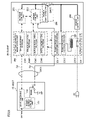
- FIG. 2 is a block diagram illustrating a configuration of the host and the client according to the first exemplary embodiment
- FIG. 3 is a flowchart illustrating a process sequence of the host and the client
- FIG. 4 is a flowchart illustrating a process sequence of the host and the client
- FIG. 5 is a block diagram illustrating a configuration of the host and the client according to the second exemplary embodiment
- FIG. 6 is a flowchart illustrating a process sequence of the host and the client
- FIG. 7 is a block diagram illustrating a configuration of a host and a client according to the third exemplary embodiment
- FIG. 8 is a block diagram illustrating a configuration of a host and a client according to the fourth exemplary embodiment
- FIG. 9 is a block diagram illustrating a configuration of a host and a client according to the fifth exemplary embodiment.
- FIG. 10 is a flowchart illustrating a process sequence of the host and the client.
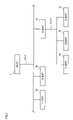
- FIG. 1 is a schematic diagram illustrating a power supply management system according to the exemplary embodiment.
- a host computer (hereinafter ‘host’) (information processor, computer) 1 is connected to client computers (hereinafter ‘clients’) (upper-level client, terminal, device) 2 a , 2 b , and 2 c through a cable CA 11 .
- clients client computers
- the client 2 c is connected to clients (lower-level client, device) 3 a , 3 b , and 3 c through a cable CA 12 .
- a tree-structured network system is indicated in the exemplary embodiment. The network system may be installed, for example, in an office.
- the host 1 may be configured as, for example, a computer, a switching hub supplying power to a communication line, or the like.
- the clients 2 a to 2 c and 3 a to 3 c may be configured as office devices, specifically for example, image forming apparatuses, printers, personal computers, or various home electric appliances connected to the network.
- the host 1 and the clients 2 a to 2 c and 3 a to 3 c are described by clearly differentiating their, function, but there may be a case that the host itself may take the function of the clients 2 a to 2 c and 3 a to 3 c.
- Each of the cables (net cable) CA 11 and CA 12 described herein refers to a cable formed of a pair of a data communication line Cd (see FIG. 2 for reference) and a power supply line Cp (see FIG. 2 for reference). That is, data is sent and received between the host 1 and the clients 2 a to 2 c through the data communication line Cd of the cable CA 11 . Data is sent and received between the client 2 c and the clients 3 a to 3 c through the data communication line Cd of the cable CA 12 .
- the host 1 supplies the electric power to the clients 2 a to 2 c through the power supply line Cp of the cable CA 11 and the client 2 c supplies the electric power to the clients 3 a to 3 c through the power supply line Cp of the cable CA 12 .
- the devices are respectively connected by the cable CA 11 or CA 12 through which the data is sent and received and the electric power is supplied.
- the host 1 , the clients 2 a to 2 c and the clients 3 a to 3 c are connected to a power supply network as a tree-structured network system.
- An image forming apparatus as the clients 2 a to 2 c in the exemplary embodiment has an AC power supply as a driving power supply in addition to the power supply lines Cp of the cables CA 11 and CA 12 . It may be considered that a technique of supplying electric power meets the standard specification called IEEE 802.3af, which supplies the electric power to the clients 2 a to 2 c and the clients 3 a to 3 c or sends and receives the data through the power supply network such as Power-over-EthernetTM.
- the data communication line Cd and the power supply line Cp are configured as a pair. However, even when the electric power is superposed on the data communication line Cd, the effect does not change.
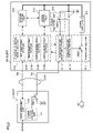
- FIG. 2 is a block diagram illustrating a configuration of the host 11 and client 21 according to the first exemplary embodiment.
- the host 11 includes a switch (change unit, switch element) SW 11 , a power supply control unit (change unit, detection unit) 111 , and a data switching unit 112 .
- Solid-line arrows shown in FIG. 2 indicate power supply paths.
- Broken-line arrows shown in FIG. 2 indicate data communication paths.
- the switch SW 11 is disposed between the power supply unit and the power supply line Cp. Specifically, when the switch SW 11 is turned on, the electric power is supplied to the client 21 through the power supply line Cp. When the switch SW 11 is turned off, the electric power is not supplied to the client 21 through the power supply line cp.
- the power supply control unit 111 turns the switch SW 11 on or turns the switch SW 11 off. That is, the power supply control unit 111 turns the switch SW 11 on when the power supply control unit 111 judges that the electric power is needed to be supplied to a power control unit (monitor unit) 211 and/or a starting condition monitoring unit (monitor unit) 214 of the client 21 that are described later.
- the power supply control unit 111 turns the switch SW 11 off when the power supply control unit 111 judges that the electric power is not needed to be supplied to the power control unit 211 and the starting condition monitoring unit 214 of the client 21 .
- the power supply control unit 111 also controls a switch (change unit, switch element) SW 21 of the power control unit 211 and a switch (change unit, switch element) SW 31 of a power switching unit 216 that are described later. That is, the power supply control unit 111 instructs a power receiving control portion (change unit) 2112 of the power control unit 211 to turn the switches SW 21 and SW 31 on or turn the switches SW 21 and SW 31 off through the data communication line Cd and through the starting condition monitoring unit 214 .
- the data switching unit 112 selects the optimal one among plural clients (see reference numerals 2 a , 2 b , and 2 c in FIG. 1 for reference) connected to the host 11 , and then the data switching unit 112 receives the data from the selected client and sends the data to the selected client.
- the data switching unit 112 communicates with the power supply control unit 111 and controls the power supply for the selected client so that the electric power is started to supply to the selected client.
- the client 21 includes a power control unit 211 , a power supply unit 212 , an engine control unit 213 , a starting condition monitoring unit (trigger monitoring unit) 214 , a network control unit 215 , a power switching unit 216 , and a power storing unit 217 .
- a power control unit 211 the client 21 includes a power control unit 211 , a power supply unit 212 , an engine control unit 213 , a starting condition monitoring unit (trigger monitoring unit) 214 , a network control unit 215 , a power switching unit 216 , and a power storing unit 217 .
- the solid-line arrows in the client 21 shown in FIG. 2 indicate power supply paths. That is, the power control unit 211 supplies the electric power to the starting condition monitoring unit 214 .
- the broken-line arrow between the power control unit 211 and the starting condition monitoring unit 214 indicates a data communication path.
- the broken-line arrows interconnected among the engine control unit 213 , the starting condition monitoring unit 214 , and the network control unit 215 indicate the data communication paths.
- the double-line arrows extending from the power supply unit 212 to the engine control unit 213 and the network control unit 215 indicates power supply paths of a DC power supply as the driving power supply.
- the power control unit 211 includes a power receiving monitoring portion (detection unit) 2111 , a power receiving control portion 2112 , and a switch SW 21 .
- the power receiving monitoring portion 2111 and the power receiving control portion 2112 are activated by the electric power supplied from the host 11 .
- the power receiving monitoring portion 2111 monitors whether or not the electric power is supplied from the host 11 .
- the power receiving control portion 2112 turns the switch SW 21 on or turns the switch SW 21 off on the basis of the monitoring result of the power receiving monitoring portion 2111 .
- the switch SW 21 when the switch SW 21 is turned on by the power receiving control portion 2112 , the electric power is supplied from an AC power supply (not shown in figures) to the power supply unit 212 .
- the switch SW 21 is turned off by the power receiving control portion 2112 , the electric power supply from the AC power supply (not shown in figures) to the power supply unit 212 is stopped.
- the power receiving control portion 2112 of the power control unit 211 turns on the switch SW 31 of the power switching unit 216 or turns off the switch SW 31 of the power switching unit 216 on the basis of the instruction of the power supply control unit 111 of the host 11 .
- the amount of power consumption of the power control unit 211 and the starting condition monitoring unit 214 is within the range of the amount of electric power supplied from the host 11 .
- the power supply control unit 111 of the host 11 instructs the power receiving control portion 2112 to turn the switch SW 31 on such that the electric power is temporarily supplied from the power storing unit 217 .
- the electric power is supplied from the host 11 to the power control unit 211 and the electric power is also supplied from the power storing unit 217 , the amount of the supplied electric power increases. Consequently, it is avoided that the amount of power consumption is larger than the amount of supplied electric power. In this manner, in the steady state, only the host 11 supplies the electric power. When the amount of power consumption is increased, the electric power is also supplied from the power storing unit 217 so as to replenish the power shortage.
- the switch SW 21 of the power control unit 211 is configured to be mechanically turned on or turned off by using an electromagnet or the like. Such the switch SW 21 may be disposed in the heating area as well. However, since the switch SW 21 applies the current to the coil, the amount of power consumption may increase at the time of turning the switch on or turning the switch off.
- the switch SW 31 of the power switching unit 216 is a semiconductor relay configured to be electrically turned on or turned off by using a transistor or the like. The amount of power consumption of the switch SW 31 at the time of turning the switch on or turning the switch off is smaller than that of the mechanical switch using the electromagnet or the like.
- the power supply unit 212 is a low voltage power supply (LVPS) built in the client 21 .
- LVPS low voltage power supply
- the power supply unit 212 supplies the electric power to the engine control unit 213 and the network control unit 215 .
- the power supply unit 212 supplies the electric power to the power storing unit 217 .
- the engine control unit 213 is to control each unit (each device) of the image forming apparatus.
- the engine control unit 213 drives and controls an exposure device, a photoreceptor drum, a fixing device, and the like (not shown in figures).
- the engine control unit 213 sends information about various switch manipulation by a user to the starting condition monitoring unit 214 .
- the starting condition monitoring unit 214 monitors various signals (trigger signals) for starting the client 21 . That is, the starting condition monitoring unit 214 monitors the starting timing of the client 21 by detecting the situation of working people in the office (monitor information, starting signal, and starting information) or the like. Specifically, the starting condition monitoring unit 214 includes a net monitoring portion 2141 , a timer monitoring portion 2142 , a sensor monitoring portion 2143 , and a switch monitoring portion 2144 . The starting condition monitoring unit 214 receives the data from the power control unit 211 , the engine control unit 213 , and the network control unit 215 and sends the data to the power control unit 211 , the engine control unit 213 , and the network control unit 215 .
- the net monitoring portion 2141 monitors the printing instruction or the like from the data switching unit 112 through the data communication line Cd. That is, the net monitoring portion 2141 judges whether or not each units of the image forming apparatus is needed to be controlled by the engine control unit 213 .
- the net monitoring portion 2141 is activated by the electric power supplied through the power supply line Cp. Accordingly, when the switch SW 11 of the host 11 is turned on, the net monitoring portion 2141 performs the monitoring operation.
- the timer monitoring portion 2142 monitors whether or not the current time is the period during office hours on the basis of the time information. For example, when the information that the office hours are from 9 a.m. to 5 p.m. is inputted in advance, the timer monitoring portion 2142 judges whether or not the current time is the period during office hours by acquiring the current time.
- the sensor monitoring portion 2143 monitors a sensor (brightness-information detecting unit) (not shown in figures) which detects turning on a light in the office where the network system is placed or the increase of the amount of daylight.
- the sensor (not shown in figures) may be configured by a sensor detecting a variety of information. For example, it may be considered that a sensor detects the operative information in the office such as unlocking of the door in the office, the amount of power consumption in the office, conditions in the office such as noises, or starting information of operating the copy machine such as preparing a document for printing on the client 21 .
- the senor detects monitor information such as a printing history, the amount of communication, the amount of electric power, the period of power distribution, detects received information such as receiving a facsimile and instructing a printing, detects operative information (printing-instruction process information, status information, power on/off information, using information, returning time, and the like) of the lower-level clients (reference numerals 3 a to 3 c in FIG. 1 ), or detects information of existence or nonexistence of security.
- monitor information such as a printing history, the amount of communication, the amount of electric power, the period of power distribution
- detects received information such as receiving a facsimile and instructing a printing
- detects operative information printing-instruction process information, status information, power on/off information, using information, returning time, and the like
- the switch monitoring portion 2144 monitors a mode changing switch disposed on a control panel (not shown in figures) of the client 21 .
- the switch monitoring portion 2144 monitors a button manipulated by a user to return from an energy-saving mode.
- the network control unit 215 is activated by the electric power supplied from the power supply unit 212 .
- the network control unit 215 performs the functions that the net monitoring portion 2141 of the starting condition monitoring unit 214 has performed until that time. In this manner, the amount of power consumption of the starting condition monitoring unit 214 is suppressed.
- the network control unit 215 sends the image data, which is sent from the host 11 through the data communication line Cd, to the engine control unit 213 .
- the power switching unit 216 has the switch SW 31 . On one side of the switch SW 31 , the switch SW 31 is connected to the power supply unit 212 and the power storing unit 217 . On the other side of the switch SW 31 , the switch SW 31 is connected to the power control unit 211 . The power receiving control portion 2112 of the power control unit 211 turns the switch SW 31 on or turns the switch SW 31 off.
- the power storing unit 217 supplies the electric power to the power control unit 211 when the switch SW 31 is turned on. That is, the power storing unit 217 replenishes the amount of power consumption of the client 21 by using a capacitor, a battery, or the like.
- the power storing unit 217 stores the electric power supplied from the power supply unit 212 when the switch SW 21 is turned on and the switch SW 31 is turned off.
- the power storing unit 217 may be the known power storing unit that is suitable for instantaneously energy supply such as a lithium-ion battery and an electric double layer capacitor.
- the lithium-ion battery or the like is suitable for driving a relay at a short time.
- FIG. 3 is a flowchart illustrating a process sequence of the host 11 and the client 21 .
- the flowchart shown in FIG. 3 illustrates a process sequence till the time when it is transferred to the starting state of monitoring the starting condition (steady state, monitoring state) after receiving the electric power through the power supply line Cp.
- the electric power is supplied to the client 21 through the power supply line Cp of the cable CA 11 .
- the power control unit 211 of the client 21 receives the electric power from the host 11 through the power supply line Cp (step 101 ).
- the power control unit 211 supplies the received electric power to the starting condition monitoring unit 214 (step 102 ).
- the electric power through the power supply line Cp is supplied to the starting condition monitoring unit 214 via the power receiving monitoring portion 2111 and the power receiving control portion 2112 .
- the power supply control unit 111 of the host 11 detects that the cable CA 11 is connected, through the data switching unit 112 (step 103 ), the starting condition monitoring unit 214 receiving the electric power is activated in order to establish the communication with the host 11 through the data communication line Cd (step 104 ). Then, the power supply control unit 111 of the host 11 confirms the power supply conditions and the like between the power receiving monitoring portion 2111 and the power receiving control portion 2112 of the power control unit 211 (step 105 ).
- the power receiving monitoring portion 2111 and the power receiving control portion 2112 report, to the power supply control unit 111 of the host 11 , the amount of power consumption on the occasion of turning on the switches SW 21 and SW 31 and turning off the switches SW 21 and SW 31 or the amount of power consumption at each mode (state) of the image forming apparatus.
- the power supply control unit 111 of the host 11 acquires, for example, information about the capability of the power supply through the power supply line Cp.
- the starting condition monitoring unit 214 starts monitoring the starting-condition (step 106 ).
- the starting condition includes various signals for starting the operation of the client 21 , for example, a signal for communicating which the host 11 instructs or a signal for preparation of a document and the like for the starting condition of the image forming apparatus.
- the power receiving monitoring portion 2111 and the power receiving control portion 2112 monitor the amount of electric power or the presence or absence of power supply. That is, the power receiving monitoring portion 2111 and the power receiving control portion 2112 monitor the presence or absence of the electric power supplied from the host 11 , and monitor the amount of power consumption of the client 21 .
- the starting condition monitoring unit 214 instructs the engine control unit 213 to change the operation mode of the image forming apparatus on the basis of the monitoring result of the timer monitoring portion 2142 . For example, the starting condition monitoring unit 214 instructs the engine control unit 213 to enter into the energy-saving mode or to return from the energy-saving mode.
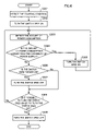
- FIG. 4 is a flowchart illustrating a process sequence of the host 11 and the client 21 .
- the flowchart in FIG. 4 shows the process sequence till the time when the image forming apparatus is entered into the operating state after the starting-condition is detected and the image forming apparatus becomes ready to operate under monitoring the starting state.
- the starting condition monitoring unit 214 detects the starting condition (step 201 ).
- the detected starting condition is reported to the power control unit 211 .
- the power receiving monitoring portion 2111 and the power receiving control portion 2112 of the power control unit 211 receiving the report detect the amount of power consumption of the client 21 (step 202 ), and report it to the power supply control unit 111 of the host 11 through the data communication line Cd.
- the power supply control unit 111 judges whether or not the amount is larger than the capability of the power supply of the host 11 by using the varieties of information acquired in advance (step 203 ). For example, when the power receiving control portion 2112 turns the switch SW 21 on so as to operate the image forming apparatus, the power supply control unit 111 judges whether or not the amount of power consumption of the client 21 is larger than the amount of electric power supplied from the host 11 .
- the power supply control unit 111 of the host 11 judges that the amount of power consumption is not larger than the amount of the supplied power at the time of turning the switch SW 21 on, the power supply control unit 111 instructs the power receiving control portion 2112 to turn on the switch SW 21 of the power control unit 211 .
- the instructed power receiving control portion 2112 turns the switch SW 21 on (step 204 ).
- the switch SW 31 of the power switching unit 216 is off. In this manner, the electric power from the power supply unit 212 is supplied to the engine control unit 213 and the network control unit 215 and then the image forming apparatus becomes ready to operate (step 205 ).
- the power supply control unit 111 of the host 11 judges that the amount of power consumption at the time of the switch SW 21 being turned on is larger than the amount of the supplied power (when the amount of power consumption increases), the power supply control unit 111 of the host 11 instructs the power receiving control portion 2112 to turn only the switch SW 31 on.
- the power receiving control portion 2112 receiving the instruction also turns on the switch SW 31 of the power switching unit 216 , while the switch SW 21 is off (step 206 ).
- the power control unit 211 is supplied with the electric power from the host 11 as well as the electric power from the power storing unit 217 so that it is avoided that the amount of power consumption exceeds the amount of the supplied power even when the switch SW 21 requiring the large amount of power consumption at the time of switching is turned on.
- the power supply control unit 111 of the host 11 instructs the power receiving control portion 2112 to turn the switch SW 21 on and to turn the switch SW 31 off (at the time of starting the printer). In this manner, the power receiving control portion 2112 turns the switch SW 21 on (step 207 ) and turns the switch SW 31 off (step 208 ). That is, the power supply control unit 111 instructs the power receiving control portion 2112 to turn the switches SW 21 and SW 31 on or turn the switches SW 21 and SW 31 off such that the switch SW 31 is turned on only in a period when the power consumption temporarily increases such as when the switch SW 21 is turned on.
- the power storing unit 217 stores the electric power from the power supply unit 212 .
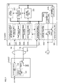
- FIG. 5 is a block diagram illustrating a configuration of the host 12 and a client 22 according to the second exemplary embodiment.
- the host 12 and the client 22 are respectively connected by a cable CA 11 including a power supply line Cp and a data communication line Cd.
- the host 12 shown in FIG. 5 is the same configuration as the host 11 shown in FIG. 2 . That is, the host 12 includes a power supply control unit (change unit, detection unit) 121 , a data switching unit 122 , and a switch (change unit, switch element) SW 12 .
- the power supply control unit 121 instructs a power receiving control portion (change unit) 2212 of a power control unit (monitor unit) 221 to turn the switches (change unit, switch element) SW 22 and SW 32 on or to turn the switches (change unit, switch element) SW 22 and SW 32 off through the data communication line Cd and a starting condition monitoring unit (monitor unit) 224 .
- the basic configuration of the client 22 shown in FIG. 5 is the same as the client 21 shown in FIG. 2 . That is, the client 22 includes the power control unit 221 , a power supply unit (main power supply) 222 , an engine control unit 223 , the starting condition monitoring unit 224 , a network control unit 225 , and a power switching unit 226 . These may be the same configurations as the power control unit 211 , the power supply unit 212 , the engine control unit 213 , the starting condition monitoring unit 214 , the network control unit 215 , and the power switching unit 216 in the client 21 , respectively.
- the power control unit 221 includes a power receiving monitoring portion (detection unit) 2211 , the power receiving control portion 2212 , and a switch SW 22 .
- the client 22 does not have a configuration corresponding to the power storing unit 217 in the client 21 .
- the starting condition monitoring unit 224 includes a net monitoring portion 2241 , a timer monitoring portion 2242 , a sensor monitoring portion 2243 , and a switch monitoring portion 2244 .
- any unit to which the electric power from the power supply unit 222 is supplied may be changed by turning on and turning off of the switch SW 32 of the power switching unit 226 .
- the units to which the electric power from the power supply unit 222 is supplied are the engine control unit 223 and the network control unit 225 .
- the switch SW 32 is turned on, the units to which the electric power from the power supply unit 222 is supplied are the engine control unit 223 and the network control unit 225 as well as the power control unit 221 and the starting condition monitoring unit 224 .
- the power receiving control portion 2212 of the power control unit 221 turns the switch SW 32 on or turns the switch SW 32 off.
- the switch SW 32 is a so-called self-holding switch that holds the state of the switch when the supply of the electric power from the power receiving control portion 2212 is stopped.
- the power supply control unit 121 controls the amount of power consumption not to be larger than the amount of the power supplied through the power supply line Cp.
- FIG. 6 is a flowchart illustrating a process sequence of the host 12 and the client 22 .
- the process sequence till the time when the switch SW 12 is turned on to start monitoring the starting condition is the same as shown in FIG. 3 and thus the description thereof is omitted.
- the starting condition monitoring unit 224 detects the starting condition (step 301 ).
- the detected starting conditions are reported to the power supply control unit 121 .
- the power supply control unit 121 instructs the power receiving monitoring portion 2211 and the power receiving control portion 2212 to turn the switch SW 22 on. In this manner, the power receiving monitoring portion 2211 and the power receiving control portion 2212 turn the switch SW 22 on (step 302 ).
- the power receiving monitoring portion 2211 and the power receiving control portion 2212 of the power control unit 221 detect the amount of power consumption of the client 22 (step 303 ) and the detected amount of power consumption is reported to the power supply control unit 121 of the host 12 through the data communication line Cd.
- the power supply control unit 121 judges whether or not the amount of power consumption is larger than the power supply capability of the host 12 by using the varieties of information acquired in advance (step 304 ). That is, the power supply control unit 121 judges whether or not the amount of power consumption of the power control unit 221 and the starting condition monitoring unit 224 is larger than the amount of the power supplied from the host 12 .
- the power supply control unit 121 of the host 12 judges that the amount of power consumption is larger than the capability of the power supply (an urgent status when further electric power should be supplied)
- the power supply control unit 121 instructs the power receiving control portion 2212 to turn the switch SW 32 of the power switching unit 226 on.
- the instructed power receiving control portion 2212 turns the switch SW 32 on (step 305 ).
- the electric power is supplied from the power supply unit 222 to the power control unit 221 and the starting condition monitoring unit 224 . That is, the power supply unit 222 supplies the electric power to all units of the client 22 that consume the electric power.
- the switch SW 12 of the host 12 is turned off while the switch SW 32 is on, there is no influence on the client 22 even when the electric power is not supplied through the power supply line Cp. Even when the switch SW 12 is turned off to stop supplying the electric power, the communication is established through the data communication line Cd. Accordingly, the data or signal is received and sent between the host 12 and the client 22 to each other.
- the power supply control unit 121 detects whether or not the switch SW 32 is turned on (step 306 ).
- the power supply control unit 121 instructs the power receiving control portion 2212 to turn the switch SW 32 off.
- the instructed power receiving control portion 2212 turns the switch SW 32 off (step 307 ).
- the power supply control unit 121 proceeds to the step 308 .
- the power supply control unit 121 judges whether or not the switch SW 22 is to be turned off (step 308 ). That is, for example, when a timer monitoring portion 2242 of the starting condition monitoring unit 224 detects that the current time is out of office hours, the power supply control unit 121 instructs the power receiving control portion 2212 to turn the switch SW 22 off so as to suppress the amount of power consumption. The instructed power receiving control portion 2212 turns the switch SW 22 off (step 309 ). In addition, when the timer monitoring portion 2242 of the starting condition monitoring unit 224 does not detect that the current time is out of office hours, the processing goes back to the step 303 .
- the exemplary embodiment is to be applied to the case the amount of power consumption of the power control unit 221 and the starting condition monitoring unit 224 is larger than the amount of the electric power supplied through the power supply line Cp, but the exemplary embodiment is also applied to the other cases.
- the operation of the image forming apparatus of the client 22 should not be stopped inadvertently. Since stopping the supply of the electric power from the host 12 makes surplus electric power within the capability of the power supply from the host 12 , more devices may be connected to the host 12 .
- FIG. 7 is a block diagram illustrating a configuration of a host 13 and a client 23 according to the third exemplary embodiment.
- the host 13 and the client 23 are respectively connected by the cable CA 11 including the power supply line Cp and the data communication line Cd.
- the host 13 shown in FIG. 7 is the same configuration as the host 11 shown in FIG. 2 . That is, the host 13 includes a power supply control unit (change unit, detection unit) 131 , a data switching unit 132 , and a switch (change unit, switch element) SW 13 .
- the power supply control unit 131 instructs a power receiving control portion (change unit) 2312 of a power control unit (monitor unit) 231 through the data communication line Cd and a starting condition monitoring unit (monitor unit) 234 to turn the switches (change unit, switch element) SW 23 and SW 33 on or turn the switches (change unit, switch element) SW 23 and SW 33 off.
- the basic configuration of the client 23 shown in FIG. 7 is the same as the client 21 shown in FIG. 2 . That is, the client 23 includes the power control unit 231 , power supply units 232 a and 232 b , an engine control unit 233 , the starting condition monitoring unit 234 , and a network control unit 235 . These units may be the same configurations as the power control unit 211 , the power supply unit 212 , the engine control unit 213 , the starting condition monitoring unit 214 , and the network control unit 215 in the client 21 , respectively. That is, the starting condition monitoring unit 234 includes a net monitoring portion 2341 , a timer monitoring portion 2342 , a sensor monitoring portion 2343 , and a switch monitoring portion 2344 .
- the client 23 has a data server 238 in association with high-functionalization of the image forming apparatus.
- the power control unit 231 includes a power receiving monitoring portion (detection unit) 2311 , a power receiving control portion 2312 , and switches SW 23 and SW 33 .
- the switches SW 23 and SW 33 are turned on or turned off by the power receiving control portion 2312 that was instructed by the power supply control unit 131 .
- the switch SW 23 is connected to the power supply unit 232 a .
- the switch SW 33 is connected to the power supply unit 232 b .
- the power supply unit 232 a is to supply the electric power to the power control unit 231 , the starting condition monitoring unit 234 , the network control unit 235 , and the data server 238 .
- the power supply unit 232 b is to supply the electric power to the engine control unit 233 and the network control unit 235 .
- the exemplary embodiment is configured to change the state of power supply to the units of the client 23 that consume the electric power by turning the switches SW 23 and SW 33 on or turning the switches SW 23 and SW 33 off.
- the switch SW 13 is on and the switches SW 23 and SW 33 are off. Accordingly, for example, in the monitor mode such as the printing instruction at waiting time, the amount of power consumption (ex. 10 W) necessary for the power control unit 231 and the starting condition monitoring unit 234 is supplied through the power supply line Cp similarly to the first and second exemplary embodiments.
- the power supply control unit 131 turns the switch SW 23 on and turn the switches SW 13 and SW 33 off. Accordingly, the electric power is not supplied through the power supply line Cp and the electric power is instead supplied from the power supply unit 232 a to the power control unit 231 , the starting condition monitoring unit 234 , the network control unit 235 , and the data server 238 . That is, by starting the power supply unit 232 a , the electric power is supplied to the operating units other than the print unit of the client 23 .
- the necessary amount of power consumption (ex. 70 W) does not be supplied through the power supply line Cp. Accordingly, the electric power is supplied by the power supply unit 232 a that supplies larger amount of the power supply than the power supply line Cp.
- the power supply control unit 131 turns the switches SW 23 and SW 33 on and turns the switch SW 13 off. In this manner, the necessary amount of power consumption (ex. 1000 W) is supplied by the power supply units 232 a and 232 b , whereby the electric power is supplied to all power consuming units of the client 23 .
- the electric power is not supplied to the power consuming units other than the operating units.
- the electric power is supplied from the optimal power supply appropriate for power consumption.
- FIG. 8 is a block diagram illustrating a configuration of a host 14 and a client 24 according to the fourth exemplary embodiment.
- the host 14 and the client 24 are respectively connected by the cable CA 11 including the power supply line Cp and the data communication line Cd.
- the host 14 shown in FIG. 8 is the same configuration as the host 11 shown in FIG. 2 . That is, the host 14 includes a power supply control unit (change unit, detection unit) 141 , a data switch unit 142 , and a switch (change unit, switch element) SW 14 .
- the power supply control unit 141 instructs a power receiving control portion (change unit) 2412 of a power control unit (monitor unit) 241 through the data communication line Cd and a starting condition monitoring unit (monitor unit) 244 to turn the switches (change unit, switch element) SW 24 and SW 34 on or to turn the switches (change unit, switch element) SW 24 and SW 34 off.
- the basic configuration of the client 24 shown in FIG. 8 is the same as the client 21 shown in FIG. 2 . That is, the client 24 includes a power control unit 241 , a power supply unit (main power supply) 242 , an engine control unit 243 , a starting condition monitoring unit 244 , a network control unit 245 , and a power switching unit 246 . These units may be the same configurations as the power control unit 211 , the power supply unit 212 , the engine control unit 213 , the starting condition monitoring unit 214 , the network control unit 215 , and the power switching unit 216 in the client 21 , respectively.
- the power control unit 241 includes a power receiving monitoring portion 2411 , a power receiving control portion 2412 , and a switch SW 24 .
- the starting condition monitoring unit 244 includes a net monitoring portion 2441 , a timer monitoring portion 2442 , a sensor monitoring portion 2443 , and a switch monitoring portion 2444 .
- the client 24 has a power detecting unit (detection unit) 249 that detects the amount of electric power of the power supply unit 242 .
- the power detecting unit 249 reports the detection result by using the power receiving control portion 2412 and the starting condition monitoring unit 244 through the data communication line Cd to the power supply control unit 141 .
- An optional device 34 of an image forming apparatus is connected to the client 24 .
- the optional device 34 is supplied with the electric power from the client 24 and is configured to receive data from the client 24 and send data to the client 24 .
- An example of the optional device 34 is a security device or the like.
- the optional device 34 is disposed outside the client 24 .
- the optional device 34 may be configured in a similar manner when it is disposed inside the client 24 .
- the power control unit 241 includes a power receiving monitoring portion (detection unit) 2411 , a power receiving control portion 2412 , and a switch SW 24 .
- the power switching unit 246 includes a switch SW 34 having two contact points a and b. When the switch SW 34 is switched to the contact point a, the electric power is supplied from the host 14 through the power supply line Cp to the optional device 34 and the power control unit 241 . When the switch SW 34 is switched to the contact point b and the switch SW 24 is turned on, the electric power is supplied from the power supply unit 242 to the optional device 34 and the power receiving control portion 2412 .
- the switch SW 24 When the switch SW 24 is turned off, the electric power is not supplied from the power supply unit 242 to the optional device 34 and the power receiving control portion 2412 . Irrespective of turning the switch SW 34 or turning the switch SW 34 off, the electric power is supplied from the host 14 through the power supply line Cp to the power control unit 241 .
- the switch SW 14 is turned on, the switch SW 24 is turned off, and the switch SW 34 is switched to the contact point b.
- the electric power is supplied through the power supply line Cp to the power control unit 241 and the starting condition monitoring unit 244 .
- the electric power is not supplied to the optional device 34 .
- the switch SW 34 is switched to the contact point a from the steady state ( 1 ). Accordingly, the electric power is supplied through the power supply line Cp to the optional device 34 as well.
- the switch SW 14 is turned on, the switch SW 24 is turned on, and the switch SW 34 is switched to the contact point b.
- the electric power is supplied through the power supply line Cp to the power control unit 241 and the starting condition monitoring unit 244 . Further, the electric power is supplied from the power supply unit 242 to the engine control unit 243 , the network control unit 245 , the optional device 34 , and the power control unit 241 .
- the switch SW 14 When the power detecting unit (detection unit) 249 judges that the electric power could be larger than the outlet capacity limit of 1500 VA (100V 15A), the switch SW 14 is turned on, the switch SW 24 is turned on, and the switch SW 34 is switched to the contact point a.
- the electric power is supplied through the power supply line Cp to the power control unit 241 , the starting condition monitoring unit 244 , and the optional device 34 , and further the electric power is supplied from the power supply unit 242 to the engine control unit 243 and the network control unit 245 . That is, by reducing the number of the units to which the electric power from the power supply unit 242 is supplied, the amount of the supplied power is suppressed.
- the power supply control unit 141 controls the host 14 to supply the electric power to optional device 34 . Accordingly, the circuit breaker is prevented from cutting off due to the over capacity exceeding the limit at the side of the client 24 .
- FIG. 9 is a block diagram illustrating a configuration of a host 15 and a client 25 according to the fifth exemplary embodiment.
- the host 15 and the client 25 are respectively connected by the cable CA 11 including the power supply line Cp and the data communication Cd.
- the host 15 shown in FIG. 9 is the same configuration as the host 11 shown in FIG. 2 . That is, the host 15 includes a power supply control unit (change unit, detection unit) 151 , a data switching unit 152 , and a switch (change unit, switch element) SW 15 .
- a power supply control unit change unit, detection unit
- a data switching unit 152 data switching unit
- a switch change unit, switch element
- the basic configuration of the client 25 shown in FIG. 9 is the same configuration as the client 21 shown in FIG. 2 . That is, the client 25 includes a power control unit (monitor unit) 251 , a power supply unit 252 , an engine control unit (change unit) 253 , a starting condition monitoring unit (monitor unit) 254 , a network control unit 255 , and a power switching unit 256 . These units may be the same configurations as the power control unit 211 , the power supply unit 212 , the engine control unit 213 , the starting condition monitoring unit 214 , the network control unit 215 , and the power switching unit 216 in the client 21 , respectively. That is, the starting condition monitoring unit 254 includes a net monitoring portion 2541 , a timer monitoring portion 2542 , a sensor monitoring portion 2543 , and a switch monitoring portion 2544 .
- the power control unit 251 includes a power receiving monitoring portion (detection unit) 2511 , a power receiving control portion (change unit) 2512 , and a latch relay (change unit) 2513 .
- the latch relay 2513 employs a normally closed contact point. Accordingly, the latch relay 2513 is turned on when the current is not applied and is turned off when the current is applied.
- the power switching unit 256 has a switch (change unit, switch element) SW 35 .
- the switch SW 35 is turned on or turned off by the engine control unit 253 .
- FIG. 10 is a flowchart illustrating a process sequence of the host 15 and the client 25 .
- the power receiving monitoring portion 2511 judges whether or not the electric power is received from the power supply line Cp (step 401 ).
- the power receiving monitoring portion 2511 instructs the power receiving control portion 2512 to drive the latch relay 2513 .
- the instructed power receiving control portion 2512 drives the latch relay 2513 to open (step 402 ). In this manner, the AC power is not supplied to the power supply unit 252 , thereby suppressing the amount of power consumption of the client 25 .
- the power receiving monitoring portion 2511 supplies the received electric power to the starting condition monitoring unit 254 (step 403 ).
- the starting condition monitoring unit 254 receiving the electric power is activated to establish the communication with the host 15 through the data communication line Cd (step 404 ).
- the power supply control unit 151 of the host 15 confirms the power supply condition or the like between the power receiving monitoring portion 2511 of the power control unit 251 and the power receiving control portion 2512 of the power control unit 251 (step 405 ).
- the starting condition monitoring unit 254 starts monitoring the starting condition (step 406 ).
- the power receiving monitoring portion 2511 judges that the electric power is not received from the power supply line Cp
- the power receiving monitoring portion 2511 takes it as the host 15 not responding to the power line communication and turns the switch SW 35 off.
- the power control unit 251 supplies the electric power to the engine control unit 253 .
- the latch relay 2513 employs the normally closed contact point, the electric power is supplied from the power supply unit 252 to the power control unit 251 .
- the various processes described in the exemplary embodiments are embodied by an application program executed by using a working memory of the hosts 11 , 12 , 13 , 14 , and 15 .
- the hosts 11 , 12 , 13 , 14 , and 15 i.e. computers
- the application program may be provided to the customers as the application program installed in a computer.
- a computer readable medium storing the program to be executed in the computer may be provided.
- the computer readable medium includes, for example, a CD-ROM or the like.
- the program is read and executed by a CD-ROM readable device (not shown in figures) or the like.
- the program may be provided, for example, by passing through a network interface via a network by a program transmitting device (not shown in figures).
- the program transmitting device for example, has a memory that is disposed in the hosts 11 , 12 , 13 , 14 , and 15 and stores the program, and a program transmitting unit providing the program through the network.
Abstract
Description
- This application is based on and claims priority under 35 USC 119 from Japanese Patent Application No. 2006-285810 filed Oct. 20, 2006.
- 1. Technical Field
- The present invention relates to a power supply management system, a terminal, an information processor, a power supply management method and a computer readable medium storing a program.
- 2. Related Art
- The related art which realizes stable operation of the whole system by managing the amount of power consumption of an apparatus connected to a network is disclosed.
- According to an aspect of the invention, there is provided a power supply management system including: an information processor; and a terminal that is connected to the information processor by a communication line and a power supply line and that is controlled for power supply by the information processor. The terminal includes a monitor unit that is capable of monitoring at least any one of a signal received from the outside through the communication line and a signal detected inside by using the electric power supplied through the power supply line, and a change unit that changes an internal power supply path so as to supply electric power other than the electric power supplied through the power supply line on the basis of the monitoring results of the monitor unit.
- Exemplary embodiment(s) of the present invention will be described in detail based on the following figures, wherein:
-
FIG. 1 is a schematic diagram illustrating a power supply management system according to the exemplary embodiment; -
FIG. 2 is a block diagram illustrating a configuration of the host and the client according to the first exemplary embodiment; -
FIG. 3 is a flowchart illustrating a process sequence of the host and the client; -
FIG. 4 is a flowchart illustrating a process sequence of the host and the client; -
FIG. 5 is a block diagram illustrating a configuration of the host and the client according to the second exemplary embodiment; -
FIG. 6 is a flowchart illustrating a process sequence of the host and the client; -
FIG. 7 is a block diagram illustrating a configuration of a host and a client according to the third exemplary embodiment; -
FIG. 8 is a block diagram illustrating a configuration of a host and a client according to the fourth exemplary embodiment; -
FIG. 9 is a block diagram illustrating a configuration of a host and a client according to the fifth exemplary embodiment; and -
FIG. 10 is a flowchart illustrating a process sequence of the host and the client. - Hereinafter, an exemplary embodiment of the invention will be described in detail with reference to the drawings.
-
FIG. 1 is a schematic diagram illustrating a power supply management system according to the exemplary embodiment. - As shown in
FIG. 1 , a host computer (hereinafter ‘host’) (information processor, computer) 1 is connected to client computers (hereinafter ‘clients’) (upper-level client, terminal, device) 2 a, 2 b, and 2 c through a cable CA11. Theclient 2 c is connected to clients (lower-level client, device) 3 a, 3 b, and 3 c through a cable CA12. As described above, a tree-structured network system is indicated in the exemplary embodiment. The network system may be installed, for example, in an office. - The host 1 may be configured as, for example, a computer, a switching hub supplying power to a communication line, or the like. The
clients 2 a to 2 c and 3 a to 3 c may be configured as office devices, specifically for example, image forming apparatuses, printers, personal computers, or various home electric appliances connected to the network. In this exemplary embodiment, the host 1 and theclients 2 a to 2 c and 3 a to 3 c are described by clearly differentiating their, function, but there may be a case that the host itself may take the function of theclients 2 a to 2 c and 3 a to 3 c. - Each of the cables (net cable) CA11 and CA12 described herein refers to a cable formed of a pair of a data communication line Cd (see
FIG. 2 for reference) and a power supply line Cp (seeFIG. 2 for reference). That is, data is sent and received between the host 1 and theclients 2 a to 2 c through the data communication line Cd of the cable CA11. Data is sent and received between theclient 2 c and theclients 3 a to 3 c through the data communication line Cd of the cable CA12. The host 1 supplies the electric power to theclients 2 a to 2 c through the power supply line Cp of the cable CA11 and theclient 2 c supplies the electric power to theclients 3 a to 3 c through the power supply line Cp of the cable CA12. As described above, in the exemplary embodiment, the devices are respectively connected by the cable CA11 or CA12 through which the data is sent and received and the electric power is supplied. In other words, the host 1, theclients 2 a to 2 c and theclients 3 a to 3 c are connected to a power supply network as a tree-structured network system. - By the power supply lines Cp of the cables CA11 and CA12, for example, it is possible to supply the electric power of the maximum 12.95 W at an input voltage in the range of 36 to 57 V. For this reason, a low-power device may be operated without an internal power supply. An image forming apparatus as the
clients 2 a to 2 c in the exemplary embodiment has an AC power supply as a driving power supply in addition to the power supply lines Cp of the cables CA11 and CA12. It may be considered that a technique of supplying electric power meets the standard specification called IEEE 802.3af, which supplies the electric power to theclients 2 a to 2 c and theclients 3 a to 3 c or sends and receives the data through the power supply network such as Power-over-Ethernet™. - As described above, the data communication line Cd and the power supply line Cp are configured as a pair. However, even when the electric power is superposed on the data communication line Cd, the effect does not change.
-
FIG. 2 is a block diagram illustrating a configuration of thehost 11 andclient 21 according to the first exemplary embodiment. - As shown in
FIG. 2 , thehost 11 includes a switch (change unit, switch element) SW11, a power supply control unit (change unit, detection unit) 111, and adata switching unit 112. Solid-line arrows shown inFIG. 2 indicate power supply paths. Broken-line arrows shown inFIG. 2 indicate data communication paths. The switch SW11 is disposed between the power supply unit and the power supply line Cp. Specifically, when the switch SW11 is turned on, the electric power is supplied to theclient 21 through the power supply line Cp. When the switch SW11 is turned off, the electric power is not supplied to theclient 21 through the power supply line cp. - The power
supply control unit 111 turns the switch SW11 on or turns the switch SW11 off. That is, the powersupply control unit 111 turns the switch SW11 on when the powersupply control unit 111 judges that the electric power is needed to be supplied to a power control unit (monitor unit) 211 and/or a starting condition monitoring unit (monitor unit) 214 of theclient 21 that are described later. The powersupply control unit 111 turns the switch SW11 off when the powersupply control unit 111 judges that the electric power is not needed to be supplied to the power control unit 211 and the startingcondition monitoring unit 214 of theclient 21. - The power
supply control unit 111 also controls a switch (change unit, switch element) SW21 of the power control unit 211 and a switch (change unit, switch element) SW31 of apower switching unit 216 that are described later. That is, the powersupply control unit 111 instructs a power receiving control portion (change unit) 2112 of the power control unit 211 to turn the switches SW21 and SW31 on or turn the switches SW21 and SW31 off through the data communication line Cd and through the startingcondition monitoring unit 214. - The
data switching unit 112 selects the optimal one among plural clients (seereference numerals FIG. 1 for reference) connected to thehost 11, and then thedata switching unit 112 receives the data from the selected client and sends the data to the selected client. When the electric power is not supplied to the selected client, thedata switching unit 112 communicates with the powersupply control unit 111 and controls the power supply for the selected client so that the electric power is started to supply to the selected client. - As shown in
FIG. 2 , theclient 21 includes a power control unit 211, apower supply unit 212, anengine control unit 213, a starting condition monitoring unit (trigger monitoring unit) 214, anetwork control unit 215, apower switching unit 216, and apower storing unit 217. - The solid-line arrows in the
client 21 shown inFIG. 2 indicate power supply paths. That is, the power control unit 211 supplies the electric power to the startingcondition monitoring unit 214. The broken-line arrow between the power control unit 211 and the startingcondition monitoring unit 214 indicates a data communication path. In addition, the broken-line arrows interconnected among theengine control unit 213, the startingcondition monitoring unit 214, and thenetwork control unit 215 indicate the data communication paths. Further, the double-line arrows extending from thepower supply unit 212 to theengine control unit 213 and thenetwork control unit 215 indicates power supply paths of a DC power supply as the driving power supply. - The power control unit 211 includes a power receiving monitoring portion (detection unit) 2111, a power
receiving control portion 2112, and a switch SW21. The powerreceiving monitoring portion 2111 and the powerreceiving control portion 2112 are activated by the electric power supplied from thehost 11. The powerreceiving monitoring portion 2111 monitors whether or not the electric power is supplied from thehost 11. The powerreceiving control portion 2112 turns the switch SW21 on or turns the switch SW21 off on the basis of the monitoring result of the power receivingmonitoring portion 2111. - Specifically, when the switch SW21 is turned on by the power
receiving control portion 2112, the electric power is supplied from an AC power supply (not shown in figures) to thepower supply unit 212. When the switch SW21 is turned off by the powerreceiving control portion 2112, the electric power supply from the AC power supply (not shown in figures) to thepower supply unit 212 is stopped. - The power
receiving control portion 2112 of the power control unit 211 turns on the switch SW31 of thepower switching unit 216 or turns off the switch SW31 of thepower switching unit 216 on the basis of the instruction of the powersupply control unit 111 of thehost 11. In the steady state, the amount of power consumption of the power control unit 211 and the startingcondition monitoring unit 214 is within the range of the amount of electric power supplied from thehost 11. However, for example, when the switch SW21 is turned on, the amount of power consumption may be increased and be larger than the amount of the supplied electric power. In consideration of this situation, the powersupply control unit 111 of thehost 11 instructs the powerreceiving control portion 2112 to turn the switch SW31 on such that the electric power is temporarily supplied from thepower storing unit 217. Accordingly, since the electric power is supplied from thehost 11 to the power control unit 211 and the electric power is also supplied from thepower storing unit 217, the amount of the supplied electric power increases. Consequently, it is avoided that the amount of power consumption is larger than the amount of supplied electric power. In this manner, in the steady state, only thehost 11 supplies the electric power. When the amount of power consumption is increased, the electric power is also supplied from thepower storing unit 217 so as to replenish the power shortage. - Additionally, the switch SW21 of the power control unit 211 is configured to be mechanically turned on or turned off by using an electromagnet or the like. Such the switch SW21 may be disposed in the heating area as well. However, since the switch SW21 applies the current to the coil, the amount of power consumption may increase at the time of turning the switch on or turning the switch off. The switch SW31 of the
power switching unit 216, for example, is a semiconductor relay configured to be electrically turned on or turned off by using a transistor or the like. The amount of power consumption of the switch SW31 at the time of turning the switch on or turning the switch off is smaller than that of the mechanical switch using the electromagnet or the like. - The
power supply unit 212 is a low voltage power supply (LVPS) built in theclient 21. When the AC power is supplied due to turning the switch SW21 on, thepower supply unit 212 supplies the electric power to theengine control unit 213 and thenetwork control unit 215. Thepower supply unit 212 supplies the electric power to thepower storing unit 217. - The
engine control unit 213 is to control each unit (each device) of the image forming apparatus. For example, in case of the image forming apparatus using electrophotography, theengine control unit 213 drives and controls an exposure device, a photoreceptor drum, a fixing device, and the like (not shown in figures). Theengine control unit 213 sends information about various switch manipulation by a user to the startingcondition monitoring unit 214. - The starting
condition monitoring unit 214 monitors various signals (trigger signals) for starting theclient 21. That is, the startingcondition monitoring unit 214 monitors the starting timing of theclient 21 by detecting the situation of working people in the office (monitor information, starting signal, and starting information) or the like. Specifically, the startingcondition monitoring unit 214 includes anet monitoring portion 2141, atimer monitoring portion 2142, asensor monitoring portion 2143, and a switch monitoring portion 2144. The startingcondition monitoring unit 214 receives the data from the power control unit 211, theengine control unit 213, and thenetwork control unit 215 and sends the data to the power control unit 211, theengine control unit 213, and thenetwork control unit 215. - Herein, the
net monitoring portion 2141 monitors the printing instruction or the like from thedata switching unit 112 through the data communication line Cd. That is, thenet monitoring portion 2141 judges whether or not each units of the image forming apparatus is needed to be controlled by theengine control unit 213. Thenet monitoring portion 2141 is activated by the electric power supplied through the power supply line Cp. Accordingly, when the switch SW11 of thehost 11 is turned on, thenet monitoring portion 2141 performs the monitoring operation. - The
timer monitoring portion 2142 monitors whether or not the current time is the period during office hours on the basis of the time information. For example, when the information that the office hours are from 9 a.m. to 5 p.m. is inputted in advance, thetimer monitoring portion 2142 judges whether or not the current time is the period during office hours by acquiring the current time. - The
sensor monitoring portion 2143 monitors a sensor (brightness-information detecting unit) (not shown in figures) which detects turning on a light in the office where the network system is placed or the increase of the amount of daylight. The sensor (not shown in figures) may be configured by a sensor detecting a variety of information. For example, it may be considered that a sensor detects the operative information in the office such as unlocking of the door in the office, the amount of power consumption in the office, conditions in the office such as noises, or starting information of operating the copy machine such as preparing a document for printing on theclient 21. For example, it may be also considered that the sensor (not shown in figures) detects monitor information such as a printing history, the amount of communication, the amount of electric power, the period of power distribution, detects received information such as receiving a facsimile and instructing a printing, detects operative information (printing-instruction process information, status information, power on/off information, using information, returning time, and the like) of the lower-level clients (reference numerals 3 a to 3 c inFIG. 1 ), or detects information of existence or nonexistence of security. - The switch monitoring portion 2144 monitors a mode changing switch disposed on a control panel (not shown in figures) of the
client 21. For example, the switch monitoring portion 2144 monitors a button manipulated by a user to return from an energy-saving mode. - The
network control unit 215 is activated by the electric power supplied from thepower supply unit 212. When the electric power is supplied to thenetwork control unit 215, thenetwork control unit 215 performs the functions that thenet monitoring portion 2141 of the startingcondition monitoring unit 214 has performed until that time. In this manner, the amount of power consumption of the startingcondition monitoring unit 214 is suppressed. Thenetwork control unit 215 sends the image data, which is sent from thehost 11 through the data communication line Cd, to theengine control unit 213. - The
power switching unit 216 has the switch SW31. On one side of the switch SW31, the switch SW31 is connected to thepower supply unit 212 and thepower storing unit 217. On the other side of the switch SW31, the switch SW31 is connected to the power control unit 211. The powerreceiving control portion 2112 of the power control unit 211 turns the switch SW31 on or turns the switch SW31 off. - The
power storing unit 217 supplies the electric power to the power control unit 211 when the switch SW31 is turned on. That is, thepower storing unit 217 replenishes the amount of power consumption of theclient 21 by using a capacitor, a battery, or the like. - The
power storing unit 217 stores the electric power supplied from thepower supply unit 212 when the switch SW21 is turned on and the switch SW31 is turned off. Thepower storing unit 217, for example, may be the known power storing unit that is suitable for instantaneously energy supply such as a lithium-ion battery and an electric double layer capacitor. The lithium-ion battery or the like is suitable for driving a relay at a short time. -
FIG. 3 is a flowchart illustrating a process sequence of thehost 11 and theclient 21. The flowchart shown inFIG. 3 illustrates a process sequence till the time when it is transferred to the starting state of monitoring the starting condition (steady state, monitoring state) after receiving the electric power through the power supply line Cp. - As shown in
FIG. 3 , when the cable CA11 is connected, the electric power is supplied to theclient 21 through the power supply line Cp of the cable CA11. Then, the power control unit 211 of theclient 21 receives the electric power from thehost 11 through the power supply line Cp (step 101). The power control unit 211 supplies the received electric power to the starting condition monitoring unit 214 (step 102). In other words, the electric power through the power supply line Cp is supplied to the startingcondition monitoring unit 214 via the power receivingmonitoring portion 2111 and the powerreceiving control portion 2112. - When the power
supply control unit 111 of thehost 11 detects that the cable CA11 is connected, through the data switching unit 112 (step 103), the startingcondition monitoring unit 214 receiving the electric power is activated in order to establish the communication with thehost 11 through the data communication line Cd (step 104). Then, the powersupply control unit 111 of thehost 11 confirms the power supply conditions and the like between the power receivingmonitoring portion 2111 and the powerreceiving control portion 2112 of the power control unit 211 (step 105). That is, the power receivingmonitoring portion 2111 and the powerreceiving control portion 2112 report, to the powersupply control unit 111 of thehost 11, the amount of power consumption on the occasion of turning on the switches SW21 and SW31 and turning off the switches SW21 and SW31 or the amount of power consumption at each mode (state) of the image forming apparatus. In addition, the powersupply control unit 111 of thehost 11 acquires, for example, information about the capability of the power supply through the power supply line Cp. - The starting
condition monitoring unit 214 starts monitoring the starting-condition (step 106). The starting condition includes various signals for starting the operation of theclient 21, for example, a signal for communicating which thehost 11 instructs or a signal for preparation of a document and the like for the starting condition of the image forming apparatus. - Additionally, when the starting
condition monitoring unit 214 starts monitoring the starting conditions, the power receivingmonitoring portion 2111 and the powerreceiving control portion 2112 monitor the amount of electric power or the presence or absence of power supply. That is, the power receivingmonitoring portion 2111 and the powerreceiving control portion 2112 monitor the presence or absence of the electric power supplied from thehost 11, and monitor the amount of power consumption of theclient 21. The startingcondition monitoring unit 214, for example, instructs theengine control unit 213 to change the operation mode of the image forming apparatus on the basis of the monitoring result of thetimer monitoring portion 2142. For example, the startingcondition monitoring unit 214 instructs theengine control unit 213 to enter into the energy-saving mode or to return from the energy-saving mode. -
FIG. 4 is a flowchart illustrating a process sequence of thehost 11 and theclient 21. - The flowchart in
FIG. 4 shows the process sequence till the time when the image forming apparatus is entered into the operating state after the starting-condition is detected and the image forming apparatus becomes ready to operate under monitoring the starting state. For example, when thehost 11 sends a printing instruction to the startingcondition monitoring unit 214 through the data communication line Cd, the startingcondition monitoring unit 214 detects the starting condition (step 201). When the startingcondition monitoring unit 214 detects the starting condition, the detected starting condition is reported to the power control unit 211. The powerreceiving monitoring portion 2111 and the powerreceiving control portion 2112 of the power control unit 211 receiving the report detect the amount of power consumption of the client 21 (step 202), and report it to the powersupply control unit 111 of thehost 11 through the data communication line Cd. The powersupply control unit 111 judges whether or not the amount is larger than the capability of the power supply of thehost 11 by using the varieties of information acquired in advance (step 203). For example, when the powerreceiving control portion 2112 turns the switch SW21 on so as to operate the image forming apparatus, the powersupply control unit 111 judges whether or not the amount of power consumption of theclient 21 is larger than the amount of electric power supplied from thehost 11. - When the power
supply control unit 111 of thehost 11 judges that the amount of power consumption is not larger than the amount of the supplied power at the time of turning the switch SW21 on, the powersupply control unit 111 instructs the powerreceiving control portion 2112 to turn on the switch SW21 of the power control unit 211. The instructed powerreceiving control portion 2112 turns the switch SW21 on (step 204). The switch SW31 of thepower switching unit 216 is off. In this manner, the electric power from thepower supply unit 212 is supplied to theengine control unit 213 and thenetwork control unit 215 and then the image forming apparatus becomes ready to operate (step 205). - Returning to the step 203, when the power
supply control unit 111 of thehost 11 judges that the amount of power consumption at the time of the switch SW21 being turned on is larger than the amount of the supplied power (when the amount of power consumption increases), the powersupply control unit 111 of thehost 11 instructs the powerreceiving control portion 2112 to turn only the switch SW31 on. The powerreceiving control portion 2112 receiving the instruction also turns on the switch SW31 of thepower switching unit 216, while the switch SW21 is off (step 206). As a result, the power control unit 211 is supplied with the electric power from thehost 11 as well as the electric power from thepower storing unit 217 so that it is avoided that the amount of power consumption exceeds the amount of the supplied power even when the switch SW21 requiring the large amount of power consumption at the time of switching is turned on. - The power
supply control unit 111 of thehost 11 instructs the powerreceiving control portion 2112 to turn the switch SW21 on and to turn the switch SW31 off (at the time of starting the printer). In this manner, the powerreceiving control portion 2112 turns the switch SW21 on (step 207) and turns the switch SW31 off (step 208). That is, the powersupply control unit 111 instructs the powerreceiving control portion 2112 to turn the switches SW21 and SW31 on or turn the switches SW21 and SW31 off such that the switch SW31 is turned on only in a period when the power consumption temporarily increases such as when the switch SW21 is turned on. - When the switch SW21 is turned on and the switch SW31 is turned off, the
power storing unit 217 stores the electric power from thepower supply unit 212. -
FIG. 5 is a block diagram illustrating a configuration of thehost 12 and aclient 22 according to the second exemplary embodiment. - As shown in
FIG. 5 , thehost 12 and theclient 22 are respectively connected by a cable CA11 including a power supply line Cp and a data communication line Cd. - The
host 12 shown inFIG. 5 is the same configuration as thehost 11 shown inFIG. 2 . That is, thehost 12 includes a power supply control unit (change unit, detection unit) 121, adata switching unit 122, and a switch (change unit, switch element) SW12. The powersupply control unit 121 instructs a power receiving control portion (change unit) 2212 of a power control unit (monitor unit) 221 to turn the switches (change unit, switch element) SW22 and SW32 on or to turn the switches (change unit, switch element) SW22 and SW32 off through the data communication line Cd and a starting condition monitoring unit (monitor unit) 224. - The basic configuration of the
client 22 shown inFIG. 5 is the same as theclient 21 shown inFIG. 2 . That is, theclient 22 includes the power control unit 221, a power supply unit (main power supply) 222, anengine control unit 223, the startingcondition monitoring unit 224, anetwork control unit 225, and apower switching unit 226. These may be the same configurations as the power control unit 211, thepower supply unit 212, theengine control unit 213, the startingcondition monitoring unit 214, thenetwork control unit 215, and thepower switching unit 216 in theclient 21, respectively. In addition, the power control unit 221 includes a power receiving monitoring portion (detection unit) 2211, the powerreceiving control portion 2212, and a switch SW22. Theclient 22 does not have a configuration corresponding to thepower storing unit 217 in theclient 21. The startingcondition monitoring unit 224 includes anet monitoring portion 2241, atimer monitoring portion 2242, asensor monitoring portion 2243, and aswitch monitoring portion 2244. - Additionally, any unit to which the electric power from the
power supply unit 222 is supplied may be changed by turning on and turning off of the switch SW32 of thepower switching unit 226. Specifically, when the switch SW32 is turned off, the units to which the electric power from thepower supply unit 222 is supplied are theengine control unit 223 and thenetwork control unit 225. When the switch SW32 is turned on, the units to which the electric power from thepower supply unit 222 is supplied are theengine control unit 223 and thenetwork control unit 225 as well as the power control unit 221 and the startingcondition monitoring unit 224. - Herein, the power
receiving control portion 2212 of the power control unit 221 turns the switch SW32 on or turns the switch SW32 off. The switch SW32 is a so-called self-holding switch that holds the state of the switch when the supply of the electric power from the powerreceiving control portion 2212 is stopped. - In the exemplary embodiment, it is assumed that the amount of power consumption at the time of switching the switches SW22 and SW32 is covered by the amount of the electric power supplied through the power supply line Cp. In addition, since the switch SW32 is the self-holding switch, the amount of power consumption of the
client 22 is suppressed when the powersupply control unit 121 of thehost 12 temporarily stops supplying the electric power to the switch SW32 at the time of turning on or turning off of the switch SW22. Accordingly, the powersupply control unit 121 controls the amount of power consumption not to be larger than the amount of the power supplied through the power supply line Cp. -
FIG. 6 is a flowchart illustrating a process sequence of thehost 12 and theclient 22. The process sequence till the time when the switch SW12 is turned on to start monitoring the starting condition is the same as shown inFIG. 3 and thus the description thereof is omitted. - For example, when the
host 12 instructs the startingcondition monitoring unit 224 to print out through the data communication line Cd, the startingcondition monitoring unit 224 detects the starting condition (step 301). When the startingcondition monitoring unit 224 detects the starting condition, the detected starting conditions are reported to the powersupply control unit 121. The powersupply control unit 121 instructs the power receivingmonitoring portion 2211 and the powerreceiving control portion 2212 to turn the switch SW22 on. In this manner, the power receivingmonitoring portion 2211 and the powerreceiving control portion 2212 turn the switch SW22 on (step 302). The powerreceiving monitoring portion 2211 and the powerreceiving control portion 2212 of the power control unit 221 detect the amount of power consumption of the client 22 (step 303) and the detected amount of power consumption is reported to the powersupply control unit 121 of thehost 12 through the data communication line Cd. The powersupply control unit 121 judges whether or not the amount of power consumption is larger than the power supply capability of thehost 12 by using the varieties of information acquired in advance (step 304). That is, the powersupply control unit 121 judges whether or not the amount of power consumption of the power control unit 221 and the startingcondition monitoring unit 224 is larger than the amount of the power supplied from thehost 12. - When the power
supply control unit 121 of thehost 12 judges that the amount of power consumption is larger than the capability of the power supply (an urgent status when further electric power should be supplied), the powersupply control unit 121 instructs the powerreceiving control portion 2212 to turn the switch SW32 of thepower switching unit 226 on. The instructed powerreceiving control portion 2212 turns the switch SW32 on (step 305). In this manner, the electric power is supplied from thepower supply unit 222 to the power control unit 221 and the startingcondition monitoring unit 224. That is, thepower supply unit 222 supplies the electric power to all units of theclient 22 that consume the electric power. Additionally, in case the switch SW12 of thehost 12 is turned off while the switch SW32 is on, there is no influence on theclient 22 even when the electric power is not supplied through the power supply line Cp. Even when the switch SW12 is turned off to stop supplying the electric power, the communication is established through the data communication line Cd. Accordingly, the data or signal is received and sent between thehost 12 and theclient 22 to each other. - In addition, the processing goes back to the step 303.
- In the step 304, when the power
supply control unit 121 of thehost 12 judges that the amount of power consumption is not larger than the capability of the power supply, the powersupply control unit 121 detects whether or not the switch SW32 is turned on (step 306). When the switch SW32 is on, the powersupply control unit 121 instructs the powerreceiving control portion 2212 to turn the switch SW32 off. The instructed powerreceiving control portion 2212 turns the switch SW32 off (step 307). When the switch SW32 is not on, the powersupply control unit 121 proceeds to the step 308. - The power
supply control unit 121 judges whether or not the switch SW22 is to be turned off (step 308). That is, for example, when atimer monitoring portion 2242 of the startingcondition monitoring unit 224 detects that the current time is out of office hours, the powersupply control unit 121 instructs the powerreceiving control portion 2212 to turn the switch SW22 off so as to suppress the amount of power consumption. The instructed powerreceiving control portion 2212 turns the switch SW22 off (step 309). In addition, when thetimer monitoring portion 2242 of the startingcondition monitoring unit 224 does not detect that the current time is out of office hours, the processing goes back to the step 303. - The exemplary embodiment is to be applied to the case the amount of power consumption of the power control unit 221 and the starting
condition monitoring unit 224 is larger than the amount of the electric power supplied through the power supply line Cp, but the exemplary embodiment is also applied to the other cases. For example, when the electric power is not supplied due to the breakdown of thehost 12 or the excessive supply of the electric power, the operation of the image forming apparatus of theclient 22 should not be stopped inadvertently. Since stopping the supply of the electric power from thehost 12 makes surplus electric power within the capability of the power supply from thehost 12, more devices may be connected to thehost 12. -
FIG. 7 is a block diagram illustrating a configuration of ahost 13 and aclient 23 according to the third exemplary embodiment. - As shown in
FIG. 7 , thehost 13 and theclient 23 are respectively connected by the cable CA11 including the power supply line Cp and the data communication line Cd. - The
host 13 shown inFIG. 7 is the same configuration as thehost 11 shown inFIG. 2 . That is, thehost 13 includes a power supply control unit (change unit, detection unit) 131, adata switching unit 132, and a switch (change unit, switch element) SW13. The powersupply control unit 131 instructs a power receiving control portion (change unit) 2312 of a power control unit (monitor unit) 231 through the data communication line Cd and a starting condition monitoring unit (monitor unit) 234 to turn the switches (change unit, switch element) SW23 and SW33 on or turn the switches (change unit, switch element) SW23 and SW33 off. - The basic configuration of the
client 23 shown inFIG. 7 is the same as theclient 21 shown inFIG. 2 . That is, theclient 23 includes thepower control unit 231,power supply units engine control unit 233, the startingcondition monitoring unit 234, and anetwork control unit 235. These units may be the same configurations as the power control unit 211, thepower supply unit 212, theengine control unit 213, the startingcondition monitoring unit 214, and thenetwork control unit 215 in theclient 21, respectively. That is, the startingcondition monitoring unit 234 includes anet monitoring portion 2341, atimer monitoring portion 2342, asensor monitoring portion 2343, and aswitch monitoring portion 2344. - The
client 23 has adata server 238 in association with high-functionalization of the image forming apparatus. - Herein, the
power control unit 231 includes a power receiving monitoring portion (detection unit) 2311, a powerreceiving control portion 2312, and switches SW23 and SW33. The switches SW23 and SW33 are turned on or turned off by the powerreceiving control portion 2312 that was instructed by the powersupply control unit 131. The switch SW23 is connected to thepower supply unit 232 a. The switch SW33 is connected to thepower supply unit 232 b. Thepower supply unit 232 a is to supply the electric power to thepower control unit 231, the startingcondition monitoring unit 234, thenetwork control unit 235, and thedata server 238. Thepower supply unit 232 b is to supply the electric power to theengine control unit 233 and thenetwork control unit 235. As described above, the exemplary embodiment is configured to change the state of power supply to the units of theclient 23 that consume the electric power by turning the switches SW23 and SW33 on or turning the switches SW23 and SW33 off. - Additionally, in the steady state (waiting time) the switch SW13 is on and the switches SW23 and SW33 are off. Accordingly, for example, in the monitor mode such as the printing instruction at waiting time, the amount of power consumption (ex. 10 W) necessary for the
power control unit 231 and the startingcondition monitoring unit 234 is supplied through the power supply line Cp similarly to the first and second exemplary embodiments. - At the time of the operation without printing data such as storing data in the
data server 238, that is, at the non-printing time, the powersupply control unit 131 turns the switch SW23 on and turn the switches SW13 and SW33 off. Accordingly, the electric power is not supplied through the power supply line Cp and the electric power is instead supplied from thepower supply unit 232 a to thepower control unit 231, the startingcondition monitoring unit 234, thenetwork control unit 235, and thedata server 238. That is, by starting thepower supply unit 232 a, the electric power is supplied to the operating units other than the print unit of theclient 23. When thedata server 238 is activated, the necessary amount of power consumption (ex. 70 W) does not be supplied through the power supply line Cp. Accordingly, the electric power is supplied by thepower supply unit 232 a that supplies larger amount of the power supply than the power supply line Cp. - At the time of printing (printing operation time), the power
supply control unit 131 turns the switches SW23 and SW33 on and turns the switch SW13 off. In this manner, the necessary amount of power consumption (ex. 1000 W) is supplied by thepower supply units client 23. - As described above, in the exemplary embodiment, the electric power is not supplied to the power consuming units other than the operating units. The electric power is supplied from the optimal power supply appropriate for power consumption.
-
FIG. 8 is a block diagram illustrating a configuration of ahost 14 and aclient 24 according to the fourth exemplary embodiment. - As shown in
FIG. 8 , thehost 14 and theclient 24 are respectively connected by the cable CA11 including the power supply line Cp and the data communication line Cd. - The
host 14 shown inFIG. 8 is the same configuration as thehost 11 shown inFIG. 2 . That is, thehost 14 includes a power supply control unit (change unit, detection unit) 141, adata switch unit 142, and a switch (change unit, switch element) SW14. The powersupply control unit 141 instructs a power receiving control portion (change unit) 2412 of a power control unit (monitor unit) 241 through the data communication line Cd and a starting condition monitoring unit (monitor unit) 244 to turn the switches (change unit, switch element) SW24 and SW34 on or to turn the switches (change unit, switch element) SW24 and SW34 off. - The basic configuration of the
client 24 shown inFIG. 8 is the same as theclient 21 shown inFIG. 2 . That is, theclient 24 includes apower control unit 241, a power supply unit (main power supply) 242, anengine control unit 243, a startingcondition monitoring unit 244, anetwork control unit 245, and apower switching unit 246. These units may be the same configurations as the power control unit 211, thepower supply unit 212, theengine control unit 213, the startingcondition monitoring unit 214, thenetwork control unit 215, and thepower switching unit 216 in theclient 21, respectively. That is, thepower control unit 241 includes a powerreceiving monitoring portion 2411, a powerreceiving control portion 2412, and a switch SW24. The startingcondition monitoring unit 244 includes anet monitoring portion 2441, atimer monitoring portion 2442, asensor monitoring portion 2443, and a switch monitoring portion 2444. - The
client 24 has a power detecting unit (detection unit) 249 that detects the amount of electric power of thepower supply unit 242. Thepower detecting unit 249 reports the detection result by using the powerreceiving control portion 2412 and the startingcondition monitoring unit 244 through the data communication line Cd to the powersupply control unit 141. - An
optional device 34 of an image forming apparatus is connected to theclient 24. Theoptional device 34 is supplied with the electric power from theclient 24 and is configured to receive data from theclient 24 and send data to theclient 24. An example of theoptional device 34 is a security device or the like. In the exemplary embodiment, theoptional device 34 is disposed outside theclient 24. However, theoptional device 34 may be configured in a similar manner when it is disposed inside theclient 24. - Herein, the
power control unit 241 includes a power receiving monitoring portion (detection unit) 2411, a powerreceiving control portion 2412, and a switch SW24. Thepower switching unit 246 includes a switch SW34 having two contact points a and b. When the switch SW34 is switched to the contact point a, the electric power is supplied from thehost 14 through the power supply line Cp to theoptional device 34 and thepower control unit 241. When the switch SW34 is switched to the contact point b and the switch SW24 is turned on, the electric power is supplied from thepower supply unit 242 to theoptional device 34 and the powerreceiving control portion 2412. When the switch SW24 is turned off, the electric power is not supplied from thepower supply unit 242 to theoptional device 34 and the powerreceiving control portion 2412. Irrespective of turning the switch SW34 or turning the switch SW34 off, the electric power is supplied from thehost 14 through the power supply line Cp to thepower control unit 241. - Additionally, at the steady state (1), the switch SW14 is turned on, the switch SW24 is turned off, and the switch SW34 is switched to the contact point b. In this state, the electric power is supplied through the power supply line Cp to the
power control unit 241 and the startingcondition monitoring unit 244. In addition, the electric power is not supplied to theoptional device 34. - Meanwhile, at the steady state (2), the switch SW34 is switched to the contact point a from the steady state (1). Accordingly, the electric power is supplied through the power supply line Cp to the
optional device 34 as well. - At the time of starting the printer, the switch SW14 is turned on, the switch SW24 is turned on, and the switch SW34 is switched to the contact point b. In this state, the electric power is supplied through the power supply line Cp to the
power control unit 241 and the startingcondition monitoring unit 244. Further, the electric power is supplied from thepower supply unit 242 to theengine control unit 243, thenetwork control unit 245, theoptional device 34, and thepower control unit 241. - When the power detecting unit (detection unit) 249 judges that the electric power could be larger than the outlet capacity limit of 1500 VA (100V 15A), the switch SW14 is turned on, the switch SW24 is turned on, and the switch SW34 is switched to the contact point a. In this state, the electric power is supplied through the power supply line Cp to the
power control unit 241, the startingcondition monitoring unit 244, and theoptional device 34, and further the electric power is supplied from thepower supply unit 242 to theengine control unit 243 and thenetwork control unit 245. That is, by reducing the number of the units to which the electric power from thepower supply unit 242 is supplied, the amount of the supplied power is suppressed. Additionally, when the powersupply control unit 141 receiving the detection result of thepower detecting unit 249 judges that the electric power could be larger than the general outlet capacity limit of 1500 VA (100V 15A), the powersupply control unit 141 controls thehost 14 to supply the electric power tooptional device 34. Accordingly, the circuit breaker is prevented from cutting off due to the over capacity exceeding the limit at the side of theclient 24. -
FIG. 9 is a block diagram illustrating a configuration of ahost 15 and aclient 25 according to the fifth exemplary embodiment. - As shown in
FIG. 9 , thehost 15 and theclient 25 are respectively connected by the cable CA11 including the power supply line Cp and the data communication Cd. - The
host 15 shown inFIG. 9 is the same configuration as thehost 11 shown inFIG. 2 . That is, thehost 15 includes a power supply control unit (change unit, detection unit) 151, adata switching unit 152, and a switch (change unit, switch element) SW15. - The basic configuration of the
client 25 shown inFIG. 9 is the same configuration as theclient 21 shown inFIG. 2 . That is, theclient 25 includes a power control unit (monitor unit) 251, apower supply unit 252, an engine control unit (change unit) 253, a starting condition monitoring unit (monitor unit) 254, anetwork control unit 255, and apower switching unit 256. These units may be the same configurations as the power control unit 211, thepower supply unit 212, theengine control unit 213, the startingcondition monitoring unit 214, thenetwork control unit 215, and thepower switching unit 216 in theclient 21, respectively. That is, the startingcondition monitoring unit 254 includes anet monitoring portion 2541, atimer monitoring portion 2542, asensor monitoring portion 2543, and aswitch monitoring portion 2544. - Herein, the power control unit 251 includes a power receiving monitoring portion (detection unit) 2511, a power receiving control portion (change unit) 2512, and a latch relay (change unit) 2513. The latch relay 2513 employs a normally closed contact point. Accordingly, the latch relay 2513 is turned on when the current is not applied and is turned off when the current is applied.
- The
power switching unit 256 has a switch (change unit, switch element) SW35. The switch SW35 is turned on or turned off by theengine control unit 253. -
FIG. 10 is a flowchart illustrating a process sequence of thehost 15 and theclient 25. - As shown in
FIG. 10 , the power receivingmonitoring portion 2511 judges whether or not the electric power is received from the power supply line Cp (step 401). When the power receivingmonitoring portion 2511 judges that the electric power is received, the power receivingmonitoring portion 2511 instructs the powerreceiving control portion 2512 to drive the latch relay 2513. The instructed powerreceiving control portion 2512 drives the latch relay 2513 to open (step 402). In this manner, the AC power is not supplied to thepower supply unit 252, thereby suppressing the amount of power consumption of theclient 25. - The power
receiving monitoring portion 2511 supplies the received electric power to the starting condition monitoring unit 254 (step 403). The startingcondition monitoring unit 254 receiving the electric power is activated to establish the communication with thehost 15 through the data communication line Cd (step 404). Then, the powersupply control unit 151 of thehost 15 confirms the power supply condition or the like between the power receivingmonitoring portion 2511 of the power control unit 251 and the powerreceiving control portion 2512 of the power control unit 251 (step 405). The startingcondition monitoring unit 254 starts monitoring the starting condition (step 406). - Meanwhile, in the step 401, when the power receiving
monitoring portion 2511 judges that the electric power is not received from the power supply line Cp, the power receivingmonitoring portion 2511 takes it as thehost 15 not responding to the power line communication and turns the switch SW35 off. After the switch SW35 is turned off, the power control unit 251 supplies the electric power to theengine control unit 253. In addition, since the latch relay 2513 employs the normally closed contact point, the electric power is supplied from thepower supply unit 252 to the power control unit 251. - Herein, the various processes described in the exemplary embodiments are embodied by an application program executed by using a working memory of the
hosts hosts hosts - The foregoing description of the exemplary embodiments of the present invention has been provided for the purposes of illustration and description. It is not intended to be exhaustive or to limit the invention to the precise forms disclosed. Obviously, many modifications and variations will be apparent to practitioners skilled in the art. The exemplary embodiments were chosen and described in order to best explain the principles of the invention and its practical applications, thereby enabling others skilled in the art to understand the invention for various embodiments and with the various modifications as are suited to the particular use contemplated. It is intended that the scope of the invention be defined by the following claims and their equivalents.
Claims (21)
Applications Claiming Priority (2)
| Application Number | Priority Date | Filing Date | Title |
|---|---|---|---|
| JP2006-285810 | 2006-10-20 | ||
| JP2006285810A JP4967592B2 (en) | 2006-10-20 | 2006-10-20 | Management system, terminal device, information processing device, and program |
Publications (2)
| Publication Number | Publication Date |
|---|---|
| US20080098250A1 true US20080098250A1 (en) | 2008-04-24 |
| US7831852B2 US7831852B2 (en) | 2010-11-09 |
Family
ID=39319472
Family Applications (1)
| Application Number | Title | Priority Date | Filing Date |
|---|---|---|---|
| US11/808,693 Expired - Fee Related US7831852B2 (en) | 2006-10-20 | 2007-06-12 | Power supply management system for changing the path of an internal power supply of a device |
Country Status (3)
| Country | Link |
|---|---|
| US (1) | US7831852B2 (en) |
| JP (1) | JP4967592B2 (en) |
| CN (1) | CN101165990B (en) |
Cited By (4)
| Publication number | Priority date | Publication date | Assignee | Title |
|---|---|---|---|---|
| US20130218363A1 (en) * | 2010-11-09 | 2013-08-22 | Panasonic Corporation | Power supply control device and power supply control method |
| US20150001941A1 (en) * | 2013-06-28 | 2015-01-01 | Lexmark International, Inc. | Systems and Methods for Power Management |
| CN104600698A (en) * | 2015-01-20 | 2015-05-06 | 华为技术有限公司 | Power supply control device and power supply control method |
| CN107769200A (en) * | 2017-11-22 | 2018-03-06 | 姜齐 | A kind of new load electric power supply programme method |
Families Citing this family (9)
| Publication number | Priority date | Publication date | Assignee | Title |
|---|---|---|---|---|
| JP5171591B2 (en) * | 2008-12-11 | 2013-03-27 | アラクサラネットワークス株式会社 | Network system and network relay device power control method |
| JP2011135749A (en) * | 2009-12-25 | 2011-07-07 | Sony Corp | Power supply apparatus, power reception device and information notification method |
| US8669740B2 (en) | 2011-01-19 | 2014-03-11 | Honda Motor Co., Ltd. | Vehicle charging system |
| WO2012133249A1 (en) * | 2011-03-25 | 2012-10-04 | 京セラ株式会社 | Power management system and power management method |
| JP2014222373A (en) * | 2013-05-13 | 2014-11-27 | Necプラットフォームズ株式会社 | Communication relay device and its power supply method |
| JP6420056B2 (en) * | 2014-04-24 | 2018-11-07 | シナプティクス・ジャパン合同会社 | Mobile terminal and display panel driver |
| KR20160025890A (en) * | 2014-08-28 | 2016-03-09 | 삼성전자주식회사 | Method for controlling an image forming apparatus connected to external device through external device interfacing unit and image forming apparatus using the same |
| KR102579881B1 (en) | 2018-03-27 | 2023-09-18 | 삼성전자주식회사 | A near field communication integrated circuit and wireless communication device including the same |
| KR102586914B1 (en) * | 2018-05-23 | 2023-10-10 | 현대자동차주식회사 | Power converting apparatus for charging vehicle battery and Method for controlling the same |
Citations (12)
| Publication number | Priority date | Publication date | Assignee | Title |
|---|---|---|---|---|
| US5938770A (en) * | 1996-07-19 | 1999-08-17 | Samsung Electronics Co., Ltd. | Display apparatus for computer system |
| US6516418B1 (en) * | 1998-07-23 | 2003-02-04 | Samsung Electronics Co., Ltd. | Portable computer having universal serial bus ports controlled power supply and a method of the same |
| US6643566B1 (en) * | 1999-01-12 | 2003-11-04 | Powerdsine Ltd. | System for power delivery over data communication cabling infrastructure |
| US7203849B2 (en) * | 2003-12-12 | 2007-04-10 | Hewlett-Packard Development Company, L.P. | Method and system for distributing power to networked devices |
| US20070277049A1 (en) * | 2006-05-25 | 2007-11-29 | Foundry Networks, Inc. | System software for managing power allocation to ethernet ports in the absence of mutually exclusive detection and powering cycles in hardware |
| US7376847B2 (en) * | 2005-06-22 | 2008-05-20 | Fortemedia, Inc. | Power distribution control circuit for multi-power domain electronic circuits |
| US7400062B2 (en) * | 2002-10-15 | 2008-07-15 | Microsemi Corp. - Analog Mixed Signal Group Ltd. | Rack level power management |
| US7433712B2 (en) * | 2003-02-06 | 2008-10-07 | Modu Ltd. | Multi-access solid state memory devices and a telephone utilizing such |
| US7441133B2 (en) * | 2002-10-15 | 2008-10-21 | Microsemi Corp. - Analog Mixed Signal Group Ltd. | Rack level power management for power over Ethernet |
| US7478251B1 (en) * | 2004-12-23 | 2009-01-13 | Cisco Technology, Inc. | Methods and apparatus for provisioning uninterruptible power for power over Ethernet applications |
| US7498692B2 (en) * | 2005-02-01 | 2009-03-03 | System Engineering International | Power over ethernet battery backup |
| US7567579B2 (en) * | 1999-08-02 | 2009-07-28 | Microsemi Corp.-Analog Mixed Signal Group Ltd. | Multiple current limits for power over ethernet controller |
Family Cites Families (9)
| Publication number | Priority date | Publication date | Assignee | Title |
|---|---|---|---|---|
| CN2050662U (en) * | 1989-03-09 | 1990-01-03 | 梁经才 | Automatic arrangement of power supply system |
| JPH0962406A (en) * | 1995-08-30 | 1997-03-07 | Toshiba Corp | Information processor |
| JP3807917B2 (en) * | 2000-09-28 | 2006-08-09 | 株式会社ディーアンドエムホールディングス | Power supply circuit for electronic equipment |
| JP2002142385A (en) * | 2000-10-30 | 2002-05-17 | Canon Inc | Server device, network equipment, network system, and control method therefor |
| JP2003029885A (en) * | 2001-07-17 | 2003-01-31 | Sony Corp | Power supply system and electronic equipment |
| JP3558059B2 (en) * | 2001-08-10 | 2004-08-25 | セイコーエプソン株式会社 | Power supply control circuit and electronic equipment |
| JP4529441B2 (en) * | 2004-01-05 | 2010-08-25 | 富士ゼロックス株式会社 | Image processing apparatus and host apparatus |
| JP2005316593A (en) * | 2004-04-27 | 2005-11-10 | Sony Corp | Power controller and power control method |
| JP2006099354A (en) * | 2004-09-29 | 2006-04-13 | Matsushita Electric Ind Co Ltd | Data transfer control device and data transfer control method |
-
2006
- 2006-10-20 JP JP2006285810A patent/JP4967592B2/en not_active Expired - Fee Related
-
2007
- 2007-06-12 US US11/808,693 patent/US7831852B2/en not_active Expired - Fee Related
- 2007-08-24 CN CN2007101477018A patent/CN101165990B/en active Active
Patent Citations (12)
| Publication number | Priority date | Publication date | Assignee | Title |
|---|---|---|---|---|
| US5938770A (en) * | 1996-07-19 | 1999-08-17 | Samsung Electronics Co., Ltd. | Display apparatus for computer system |
| US6516418B1 (en) * | 1998-07-23 | 2003-02-04 | Samsung Electronics Co., Ltd. | Portable computer having universal serial bus ports controlled power supply and a method of the same |
| US6643566B1 (en) * | 1999-01-12 | 2003-11-04 | Powerdsine Ltd. | System for power delivery over data communication cabling infrastructure |
| US7567579B2 (en) * | 1999-08-02 | 2009-07-28 | Microsemi Corp.-Analog Mixed Signal Group Ltd. | Multiple current limits for power over ethernet controller |
| US7400062B2 (en) * | 2002-10-15 | 2008-07-15 | Microsemi Corp. - Analog Mixed Signal Group Ltd. | Rack level power management |
| US7441133B2 (en) * | 2002-10-15 | 2008-10-21 | Microsemi Corp. - Analog Mixed Signal Group Ltd. | Rack level power management for power over Ethernet |
| US7433712B2 (en) * | 2003-02-06 | 2008-10-07 | Modu Ltd. | Multi-access solid state memory devices and a telephone utilizing such |
| US7203849B2 (en) * | 2003-12-12 | 2007-04-10 | Hewlett-Packard Development Company, L.P. | Method and system for distributing power to networked devices |
| US7478251B1 (en) * | 2004-12-23 | 2009-01-13 | Cisco Technology, Inc. | Methods and apparatus for provisioning uninterruptible power for power over Ethernet applications |
| US7498692B2 (en) * | 2005-02-01 | 2009-03-03 | System Engineering International | Power over ethernet battery backup |
| US7376847B2 (en) * | 2005-06-22 | 2008-05-20 | Fortemedia, Inc. | Power distribution control circuit for multi-power domain electronic circuits |
| US20070277049A1 (en) * | 2006-05-25 | 2007-11-29 | Foundry Networks, Inc. | System software for managing power allocation to ethernet ports in the absence of mutually exclusive detection and powering cycles in hardware |
Cited By (6)
| Publication number | Priority date | Publication date | Assignee | Title |
|---|---|---|---|---|
| US20130218363A1 (en) * | 2010-11-09 | 2013-08-22 | Panasonic Corporation | Power supply control device and power supply control method |
| US9134709B2 (en) * | 2010-11-09 | 2015-09-15 | Panasonic Intellectual Property Management Co., Ltd. | Power supply control device and power supply control method |
| US20150001941A1 (en) * | 2013-06-28 | 2015-01-01 | Lexmark International, Inc. | Systems and Methods for Power Management |
| CN104600698A (en) * | 2015-01-20 | 2015-05-06 | 华为技术有限公司 | Power supply control device and power supply control method |
| US10175743B2 (en) | 2015-01-20 | 2019-01-08 | Huawei Technologies Co., Ltd. | Power supply control apparatus and method for controlling power supply |
| CN107769200A (en) * | 2017-11-22 | 2018-03-06 | 姜齐 | A kind of new load electric power supply programme method |
Also Published As
| Publication number | Publication date |
|---|---|
| US7831852B2 (en) | 2010-11-09 |
| CN101165990A (en) | 2008-04-23 |
| JP4967592B2 (en) | 2012-07-04 |
| CN101165990B (en) | 2012-02-01 |
| JP2008104309A (en) | 2008-05-01 |
Similar Documents
| Publication | Publication Date | Title |
|---|---|---|
| US7831852B2 (en) | Power supply management system for changing the path of an internal power supply of a device | |
| CN110058670B (en) | Image forming apparatus and control method | |
| CN102006385B (en) | Image forming apparatus | |
| US9430016B2 (en) | Information processing apparatus capable of switching patterns to be compared with data received by network interface control method for information processing apparatus, and computer-readable storage medium | |
| US20130057883A1 (en) | Apparatus and method for deactivating power-saving mode, relay device, and computer-readable storage medium for computer program | |
| JP4725621B2 (en) | Image forming apparatus, image forming apparatus control method, and program executed by image forming apparatus | |
| US8914655B2 (en) | Image forming apparatus and control method | |
| US20090091182A1 (en) | Image formation apparatus capable of receiving power from a plurality of power sources and control method performed in such image formation apparatus | |
| JP6873665B2 (en) | Printing device, control method of printing device, and program | |
| JP2010201770A (en) | Image forming device | |
| US20120200157A1 (en) | Electronic apparatus, system and method of controlling electric power supply, and recording medium storing electric power supply control program | |
| JP2010157789A (en) | Multifunctional device and operation panel unit | |
| WO2005011990A1 (en) | Power source device and communication system | |
| US20160150111A1 (en) | Electronic Device that Detects Return Timing in Low Electric Power Consumption Mode with Low Electric Power Consumption | |
| JP2015011509A (en) | Image forming apparatus | |
| US8041966B2 (en) | Electric power supply system, terminal, electric power supply method and computer readable medium | |
| JP2010218189A (en) | Electric power supply system and electric power supply control method for image forming device | |
| JP6207261B2 (en) | Image forming apparatus | |
| JP2014044437A (en) | Image forming apparatus | |
| JP4188496B2 (en) | Power consumption control method and power consumption control system | |
| JP6282097B2 (en) | Information processing apparatus, information processing apparatus control method, and program | |
| US20150201100A1 (en) | Image forming apparatus, controlling method therefor, and storage medium | |
| JP2007060150A (en) | Power supply feed control apparatus and its control method, computer program and storage medium | |
| JP5061571B2 (en) | Management system, information processing device, terminal device, and program | |
| US20130194602A1 (en) | Image Processing Device and Image Processing Unit |
Legal Events
| Date | Code | Title | Description |
|---|---|---|---|
| AS | Assignment |
Owner name: FUJI XEROX CO., LTD., JAPAN Free format text: ASSIGNMENT OF ASSIGNORS INTEREST;ASSIGNORS:YAMAZAKI, YUKIO;YAMAGUCHI, TAKETOSHI;AZUMA, KOUICHI;REEL/FRAME:019454/0692 Effective date: 20070605 |
|
| FPAY | Fee payment |
Year of fee payment: 4 |
|
| FEPP | Fee payment procedure |
Free format text: MAINTENANCE FEE REMINDER MAILED (ORIGINAL EVENT CODE: REM.) |
|
| LAPS | Lapse for failure to pay maintenance fees |
Free format text: PATENT EXPIRED FOR FAILURE TO PAY MAINTENANCE FEES (ORIGINAL EVENT CODE: EXP.); ENTITY STATUS OF PATENT OWNER: LARGE ENTITY |
|
| STCH | Information on status: patent discontinuation |
Free format text: PATENT EXPIRED DUE TO NONPAYMENT OF MAINTENANCE FEES UNDER 37 CFR 1.362 |
|
| FP | Lapsed due to failure to pay maintenance fee |
Effective date: 20181109 |